calculation of the combined torsional mesh stiffness of ...ansys the models offer the possibility to...
TRANSCRIPT

Strojniški vestnik - Journal of Mechanical Engineering 57(2011)11, 810-818 Paper received: 07.12.2010DOI: 10.5545/sv-jme.2010.248 Paper accepted: 02.08.2011
*Corr. Author’s Address: Institute for Machine Elements, Gears and Transmissons, Gottlieb-Daimler-Str., 67663 Kaiserslautern, Germany, [email protected]
Calculation of the Combined Torsional Mesh Stiffness of Spur Gears with Two- and Three-Dimensional Parametrical FE
ModelsKiekbusch, T. ‒ Sappok, D. ‒ Sauer, B. ‒ Howard, I.
Timo Kiekbusch1,* ‒ Daniel Sappok1 ‒ Bernd Sauer1 ‒ Ian Howard2
1 University of Kaiserslautern, Institute for Machine Elements, Gears and Transmissions, Germany 2 Curtin University Perth, Department of Mechanical Engineering, Australia
The torsional mesh stiffness is one of the most important characteristics of spur gears. This paper presents the development of detailed two- and three-dimensional finite element models which can be used to calculate the torsional mesh stiffness. Using the parametrical design language of the FE software ANSYS the models offer the possibility to generate various different pairs of spur gears and include an adaptive meshing algorithm for the contact zones. Due to the short computation times the 2D model is well suited to simulate a variety of different gear pairs in a short time period. The more complex 3D model features more options in terms of investigating tooth face modifications for further studies. The resulting values of the torsional stiffness can be used – for example – in multi body simulations of gearboxes.
The results from the 2D FEA are used to derive a simple formula for the combined torsional stiffness of spur gears in mesh. The results presented are based on the individual stiffness of the three main components – body, teeth and contact. Hence, the introduced formula uses these three parts to determine the overall stiffness for a wide range of gears and gear ratio combinations.
Finally, the results from both the two- and three-dimensional finite element model and the derived formula are compared and the results from the 3D model are checked against results obtained by analytical equations.©2011 Journal of Mechanical Engineering. All rights reserved. Keywords: gear dynamic modelling, spur gear, finite element modelling, torsional mesh stiffness, contact stiffness
0 INTRODUCTION
Gears are the main component of many different kinds of rotating machinery and they are often a critical part to the function of the machinery. There have been many attempts in recent years to understand and describe the process of the meshing of spur gears. As the process of meshing is very complex and difficult to describe, the finite element analysis is the method of choice to investigate the underlying relationships.
The approach used in this paper to determine the stiffness of spurs gears in mesh is the development of a FE model of the complete gear arrangement. Recent studies on this topic [1] to [4] have shown that these models produce the best results in comparison with single-tooth models or partial teeth models. As computer hardware and FE software advances, working with these rather complex models is now feasible.
1 THE FINITE ELEMENT GEAR MODELS
In the following sections the development of the two- and three-dimensional finite element models is described. This involves the fully parametrical creation of the gear shape, the meshing and the simulation process including the adaptive meshing.
1.1 2D FE Model
Fully parametrical APDL-scripts (ANSYS Parametric Design Language) are used to describe the geometry of the gears and to control the simulation process. The first step is the generation of the geometry consisting of lines and areas, which in the next step are meshed with a relatively coarse FE-mesh. The result is a FE model of pinion and gear which is shown in Fig. 1.
The process of creating various different pairs of gears is automated with the powerful

Strojniški vestnik - Journal of Mechanical Engineering 57(2011)11, 810-818
811Calculation of the Combined Torsional Mesh Stiffness of Spur Gears with Two- and Three-Dimensional Parametrical FE Models
design language of ANSYS. Without changing the model itself many parameters like modulus, number of teeth, shaft radius etc. can easily be varied as all parameters are provided in a data input file. This file is loaded during the preprocessing.
Fig. 1. Result from the first APDL-script; pre-meshed geometry
As the contact between pinion and gear is the most important and critical part of the gear simulation the description of the tooth involutes and feet require the highest possible precision during the modelling process. Therefore, both geometric details are generated by using a very high number of keypoints. The location of these points is calculated on the basis of the data input file. The keypoints are connected with splines to represent the outline of the tooth geometry. After adding the gear body the areas created are meshed with a coarse mesh. This model (see Fig. 1) is the basis for the next steps of the modelling process namely the mesh refinement at the contact point(s). This refinement is realised using another APDL-Script. The result is shown in Fig. 2. This script also adds the constraints, contact elements and different torque loads to the model, solves and post processes the job. The constraints used in the model are as follows: the hub of the gear is completely constrained from motion; the nodes at the hub of the pinion can only rotate around the centre of the pinion. The torque is applied using a force on every node at the driving gear’s hub, adding up to the specified torque.
A quasi-static simulation method is used for the determination of the mesh stiffness. This means that the stiffness is calculated at several
different angular positions of the gears. Therefore, the gears have to be rotated to the corresponding position before the model is solved. At every roll angle the contact point(s) change so that the mesh refinement at the contact point(s) require an adaptive remesh algorithm which takes into account the actual contact situation.
a) b)Fig. 2. Adaptive refining of the mesh at the
contact point(s); a) remeshed contact for single contact, b) remeshed contact for double contact
During the automated postprocessing the following results are extracted from the model: combined torsional mesh stiffness, deformation of gear body, teeth and contact zone for both pinion and gear. This data is written to a text file for further processing.
When analysing gears with tooth shape errors or profile correction, an initial gap between the teeth can occur. In order to create a very flexible model which can be used in further studies, the model was built to be able to solve problems including an initial gap between meshing teeth. Typically a static FE model cannot be solved if some parts of the model do not have enough constraints as the stiffness matrix becomes singular [5]. This can happen, for example, if a contact is not initially closed and in this case the pinion can rotate a small angle without any resistance or stiffness.
To avoid rigid body motion, a weak spring is attached to the pinion. This small stiffness prevents the unintentional rotational motion. This spring is only used for the initial simulation step with a very small torque just to get the teeth in contact. When the actual load torque is applied, the spring is disabled using the birth/death of elements command [6]. This approach can handle much bigger gaps (rigid body motion) than the

Strojniški vestnik - Journal of Mechanical Engineering 57(2011)11, 810-818
812 Kiekbusch, T. ‒ Sappok, D. ‒ Sauer, B. ‒ Howard, I.
automatic adjustment which tends to be used by default.
1.2 3D FE Model
There are some restrictions when using a two dimensional FE model for the analysis of spur gears in mesh. For example, simulating helical gears or applying tooth face modifications in the direction of the rotation axis of the gear like crowning or face angle correction is not possible. By using a three dimensional FE model these restrictions can be evaded. Furthermore, the influence of misalignment between the rotation axes of the gears as well as shaft centre distance changes on the mesh stiffness can be investigated. The disadvantages of a three dimensional versus a two dimensional model are higher complexity and hardware requirements as well as computation times.
In order to overcome the restrictions that are given by the 2D model a three dimensional FE model built on the latter was developed. Again a fully parametrical approach was used to create the shape of the gears and an initial coarse mesh. In addition the model was designed to support the modelling of helical gears and the application of tooth face modifications for further studies.
To create the gear model, each gear wheel is sliced into multiple layers along the rotation axis. For each layer, the two dimensional shape of the gear is modelled by keypoints which are connected with straights, arcs and splines. The tooth involutes and roots are described with a high number of keypoints to provide a very high accuracy like in the 2D model. As each 2D shape of the gear is built separately, the tooth shape can be changed along the rotation axis. This procedure is a prerequisite to model helical gears and to apply the above mentioned tooth face modifications.
Only the teeth which are involved in one mesh cycle are created for each gear. The surrounding teeth have only a subsidiary influence on the mesh stiffness but demand a higher amount of elements which leads to higher computation times and hardware requirements. The gear bodies are completely modelled.
During the modelling process the gears are completely meshed using a mapped meshing with hexahedral elements. In this stage, the mesh
in the area of contact, that is on the tooth faces on the loaded side of the teeth, is comparatively coarse. Mesh transitions between the body areas adjacent to modelled teeth and the rest of the gear body are used to reduce the amount of elements. A completely meshed gear pair is shown in Fig. 3.
Fig. 3. Meshed gear pair created during the model build process
A relatively fine mesh is needed to accurately simulate the non-linear contact deformation between the tooth faces. There are two options to refine the mesh in the area of contact during the simulation process. The first one is to adaptively refine the mesh at the position(s) were the tooth face contact(s) occurs. The second one is to refine the complete tooth faces on the loaded side of the teeth. Fig. 4 shows the mesh refinement for two meshing angles with the first option.
The modelling process generates a model database file and a parameter file which comprises all necessary parameters. These files are used by an APDL-script in which the boundary conditions and the contact elements are created, the solving process is started and finally a fully automated postprocessing is conducted.
In order to close an initial gap between the tooth faces and avoid rigid body motion, the usage of a small stiffness spring attached to the driving gear’s hub is adopted from the 2D model. This procedure is extended with a method to compute the spring stiffness and the initial torque load according to the actual gap size. Thereby the amount of simulation steps to close the initial gap can be reduced to a minimum which consequently reduces the simulation time.
During the postprocessing the same results as within the 2D model are extracted.
Strojniški vestnik - Journal of Mechanical Engineering 57(2011)11, 810-818
813Calculation of the Combined Torsional Mesh Stiffness of Spur Gears with Two- and Three-Dimensional Parametrical FE Models
That is the combined torsional mesh stiffness, the deformation of gear body, teeth and contact zone for pinion and gear.
2 THE COMBINED TORSIONAL MESH STIFFNESS
The definition of the combined torsional mesh stiffness Km used in this paper is the quotient of input load T [Nm] and driving gear hub rotation under load T.E. [rad] [6] to [8]:
K TT Em =
. .. (1)
This definition can be used for the dynamic simulation of spur gear systems as it directly describes the relation between load torque and relative motion of the gears.
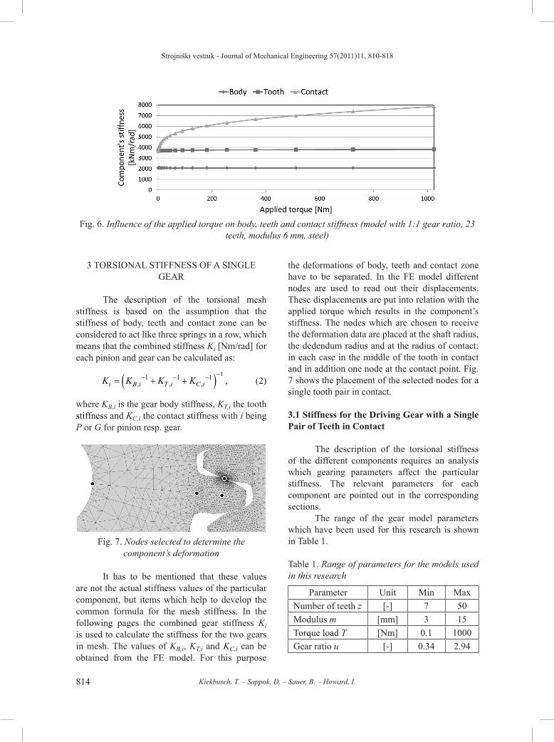
In 2001, Jia [2] introduced a common formula describing the combined torsional mesh stiffness by body and tooth bending stiffness. This simplification neglects the effect of the applied torque on the gearing's stiffness. The results from the FE model, however, show that there is an influence of the torque on the resulting combined torsional mesh stiffness as shown in Fig. 5.
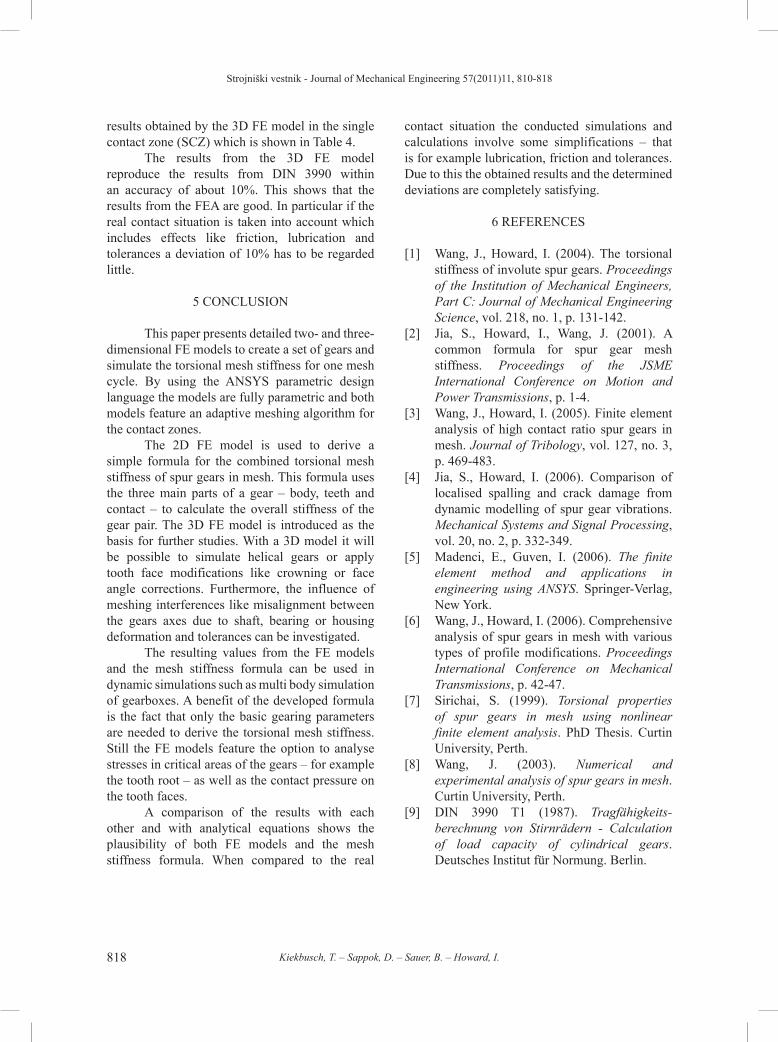
The studies of the deformational behaviour of the gear wheels show that the stiffness of gear body and teeth are almost load-independent while the contact deformation is non-linear, as a Hertzian contact occurs between the teeth of the gears. The influence of the applied torque on the component’s stiffness is shown in Fig. 6. The position and width of the handover region between single and double contact zone are also torque-dependent which has also been shown previously [1].
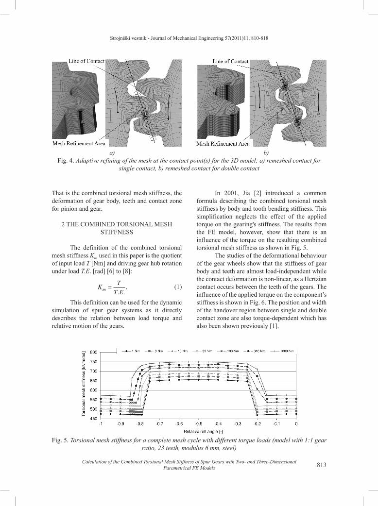
a) b)Fig. 4. Adaptive refining of the mesh at the contact point(s) for the 3D model; a) remeshed contact for
single contact, b) remeshed contact for double contact
Fig. 5. Torsional mesh stiffness for a complete mesh cycle with different torque loads (model with 1:1 gear ratio, 23 teeth, modulus 6 mm, steel)
Strojniški vestnik - Journal of Mechanical Engineering 57(2011)11, 810-818
814 Kiekbusch, T. ‒ Sappok, D. ‒ Sauer, B. ‒ Howard, I.
3 TORSIONAL STIFFNESS OF A SINGLE GEAR
The description of the torsional mesh stiffness is based on the assumption that the stiffness of body, teeth and contact zone can be considered to act like three springs in a row, which means that the combined stiffness Ki [Nm/rad] for each pinion and gear can be calculated as:
K K K Ki B i T i C i= + +( )− − − −
, , , ,1 1 1 1 (2)
where KB,i is the gear body stiffness, KT,i the tooth stiffness and KC,i the contact stiffness with i being P or G for pinion resp. gear.
Fig. 7. Nodes selected to determine the component’s deformation
It has to be mentioned that these values are not the actual stiffness values of the particular component, but items which help to develop the common formula for the mesh stiffness. In the following pages the combined gear stiffness Ki is used to calculate the stiffness for the two gears in mesh. The values of KB,i, KT,i and KC,i can be obtained from the FE model. For this purpose
the deformations of body, teeth and contact zone have to be separated. In the FE model different nodes are used to read out their displacements. These displacements are put into relation with the applied torque which results in the component’s stiffness. The nodes which are chosen to receive the deformation data are placed at the shaft radius, the dedendum radius and at the radius of contact; in each case in the middle of the tooth in contact and in addition one node at the contact point. Fig. 7 shows the placement of the selected nodes for a single tooth pair in contact.
3.1 Stiffness for the Driving Gear with a Single Pair of Teeth in Contact
The description of the torsional stiffness of the different components requires an analysis which gearing parameters affect the particular stiffness. The relevant parameters for each component are pointed out in the corresponding sections.
The range of the gear model parameters which have been used for this research is shown in Table 1.
Table 1. Range of parameters for the models used in this research
Parameter Unit Min MaxNumber of teeth z [-] 7 50Modulus m [mm] 3 15Torque load T [Nm] 0.1 1000Gear ratio u [-] 0.34 2.94
Fig. 6. Influence of the applied torque on body, teeth and contact stiffness (model with 1:1 gear ratio, 23 teeth, modulus 6 mm, steel)

Strojniški vestnik - Journal of Mechanical Engineering 57(2011)11, 810-818
815Calculation of the Combined Torsional Mesh Stiffness of Spur Gears with Two- and Three-Dimensional Parametrical FE Models
3.1.1 Stiffness of the Gear Body
The stiffness of the gear body is assumed to only depend on the following parameters: shaft radius rs dedendum radius rd, face width w and Young’s modulus E.
A simplified model (see Fig. 8) is used to analyse the influence of the above mentioned parameters on the body’s stiffness. Different combinations of parameters were used to come to the following Eq.:
K c E w r r rB P B d s s,. .ln ,= ⋅ ⋅ ⋅ −( ) ⋅1 6 1 6 (3)
where cB is a coefficient which was found out to be 9.555e-4.
The results from this equation reproduce the results from the FE model within an accuracy of about 5% for gear bodies with a outer radius between 10 and 200 mm and various inner radii.
Fig. 8. Simplified model of the gear body with applied constraints and forces
3.1.2 Bending Stiffness of the Teeth
As the teeth basically bend under load, the assumption is made that the parameters that influence the stiffness of the teeth are the same as those of a bending beam. These parameters are: height and width w of the teeth and Young’s modulus E. The influence of the radius at which the tooth is located and the tooth height was taken into account with the parameters modulus m and number of teeth z. This results in the stiffness of the tooth KT,P:
K c E w m zT P T,. ,= ⋅ ⋅ ⋅ ⋅2 2 2 (4)
where cT is a coefficient which was found out to be 3.2e-5. The results from this Eq. are within 7% of the results from the FE model for the parameter range analysed.
3.1.3 Stiffness of the Teeth Contact
In contrast to the stiffness mentioned above, the stiffness of the contact between the meshing teeth is highly non-linear with the load as it is a Hertzian contact between two curved surfaces. Therefore, the load torque T needs to be considered in the equation describing the contact stiffness. In addition, the following parameters have been found out to have a significant influence: modulus m and number of teeth z, contact radius, Young’s modulus E and face width w. The contact stiffness is approximated by:
K c E w m z TC P C,. . ,= ⋅ ⋅ ⋅ ⋅ ⋅1 85 2 0 105 (5)
where the coefficient cC is 7.937e-5. The results for the contact stiffness were found to be within 10% of the results from the FE model.
3.2 Stiffness for the Driven Gear with a Single Pair of Teeth in Contact
The stiffness values determined above are related to the driving gear (index P). With the given gear ratio u, the driven gear’s stiffness (index G) can be directly deduced taking into account that both load torque and radius of contact are u-times the respective torque and contact radius of the driving gear. So the body, teeth and contact stiffnesses are calculated by:
K K u K zzi G i P i PP
G, , , ,= ⋅ = ⋅
22
(6)
with i being the indices B, T and C for body, teeth and contact. It has to be mentioned that the parameters of the driven gear have to be used for the calculation of its stiffness (e.g. zG, EG).
3.3 Stiffness in the Double Contact Zone
The body’s stiffness value in the double contact zone is obtained by adding the factor fB. The only difference between single and double contact for the body stiffness is the width of the

Strojniški vestnik - Journal of Mechanical Engineering 57(2011)11, 810-818
816 Kiekbusch, T. ‒ Sappok, D. ‒ Sauer, B. ‒ Howard, I.
area which is affected by the load. This influence is considered to be rather small which was confirmed by the FE model. Hence, the factor fB was found to be equal to 1.1:
K f K Ki B B i B i B, , , , , ,. ,double single single= ⋅ = ⋅1 1 . (7)
The description of the double contact zone teeth stiffness assumes that both teeth pairs share the load equally. This means that each tooth’s deformation is half the deformation as in the single contact zone. This results in a stiffness value twice as high as for the single contact:
K Ki T i T, , , , .double single= ⋅2 (8)
The evaluation of the contact stiffness shows that the difference between single and double contact cannot only be described by a simple factor but by an additional change of the exponent for the applied load (cf. Eq. (5)):
K c E w m z Ti C C, ,. . ,double = ⋅ ⋅ ⋅ ⋅ ⋅1 85 2 0 068 (9)
where cC is 1.1905e-4.
3.4 The Formula for the Combined Torsional Mesh Stiffness
The stiffness for the single gear (KP, KG) is calculated by assuming all three springs in a row as mentioned above. The combined torsional mesh stiffness Km can be derived by considering the two gears as two springs in series (see Fig. 9):
K K Km P G= +( )− − −1 1 1. (10)
The results from the formula are within 10% from the 2D FE model’s results for most input parameter sets. This accuracy seems to be good enough for most of the cases where the formula can be used as there are many other different factors which influence the value of the mesh stiffness, like the shaft to collar connection and the lubrication of the gears.
Fig. 9. Simplified model of the combined torsional mesh stiffness of two gears in mesh
A simple modification during the calculation can be made to take into account the small variation of the stiffness inside the single or double contact zone. Adding a quadratic correction term will result in a lower difference between the simulated and the calculated values over the whole mesh cycle (see Fig. 10). The modified stiffness Km* against the distance from the actual relative roll angle to the centre of the single resp. double contact zone ΔΩ is:
K K cm m* ( ),= ⋅ − ⋅1 2∆© (11)
with the factor c which has to be adapted on basis of the FE model.
The determination of the position and width of the hand-over region, however, still needs further investigation which can be done using the FE model.
Fig. 10. Comparison of the FE results with quadratic correction term (Eq. (11))

Strojniški vestnik - Journal of Mechanical Engineering 57(2011)11, 810-818
817Calculation of the Combined Torsional Mesh Stiffness of Spur Gears with Two- and Three-Dimensional Parametrical FE Models
4 RESULTS
Due to the fact that the FEA of a spur gear pair is complex and therefore prone to errors the results have to be checked for plausibility. Hence the results from the 2D and 3D model as well as the mesh stiffness formula are compared with each other. Additionally, the results from the 3D model are checked against analytical results according to DIN 3990 [9]. A variety of gear pairs has been used for this comparison. Table 2 shows an excerpt from the compared gear pairs.
Table 2. Investigated gear pairs (excerpt)
Variant-No. 1 2 3 4z1 23 25 36 13z2 23 25 43 31m [mm] 6 2 11 4α [°] 20 20 20 20w1 [mm] 16 28 58 16w2 [mm] 15 24 50 15Rs1 [mm] 15 8 80 10Rs2 [mm] 15 8 100 20E-Modulus [GPa] 210 210 210 210
4.1 2D – 3D – Mesh Stiffness Formula
The torsional mesh stiffness has been calculated for the single contact zone (SCZ) and the double contact zone (DCZ) to check if the two FE models and the mesh stiffness formula produce consistent results.
Table 3 shows the stiffness results and the proportion between FE and mesh stiffness formula for each FE model.
The results show a maximum deviation of 10% that implies that the FEA and mesh stiffness formula produce consistent results for the torsional mesh stiffness.
4.2 3D – DIN 3990
DIN 3990 provides methods to calculate the load capacity of cylindrical gears which includes the determination of the tooth spring stiffness. That is the normal tooth load which is needed to deform a meshing tooth pair with 1 mm tooth width perpendicular to the tooth involute for 1 mm. This deformation corresponds to the base circle arc length and thus a rotation angle which can be converted into the before defined torsional mesh stiffness. These results are compared to
Table 3. Comparison of the torsional mesh stiffness (Km_MSF) between 2D (Km_2D), 3D FE simulation (Km_3D) and the mesh stiffness formula (italic: proportion values)
Variant-No. 1 2 3 4Torque Load [Nm] 1000 75 1000 100
SCZKm_MSF [106 Nm/rad] 0.562 1.00 0.152 1.00 22.8 1.00 0.100 1.00Km_2D [106 Nm/rad] 0.573 1.02 0.146 0.96 20.2 0.89 0.098 0.98Km_3D [106 Nm/rad] 0.594 1.06 0.154 1.01 22.1 0.97 0.102 1.02
DCZKm_MSF [106 Nm/rad] 0.722 1.00 0.206 1.00 31.4 1.00 0.138 1.00Km_2D [106 Nm/rad] 0.751 1.04 0.207 1.00 29.7 0.95 0.141 1.02Km_3D [106 Nm/rad] 0.781 1.08 0.215 1.04 30.9 0.98 0.145 1.05
Table 4. Comparison of the torsional mesh stiffness between 3D FE simulation (Km_3D) and DIN 3990 (Km_DIN)
Variant-No. 1 2 3 4Torque Load [Nm] 1000 75 1000 100Tooth Spring Stiffness [N/(mm∙μm)] 15.1 15.0 17.4 14.4Linear Distributed Load [N/mm] 966 125 101 256
SCZKm_3D [106 Nm/rad] 0.594 0.154 22.1 0.102Km_DIN [106 Nm/rad] 0.652 0.159 24.0 0.103Km_3D / Km_DIN 0.91 0.97 0.92 0.99
Strojniški vestnik - Journal of Mechanical Engineering 57(2011)11, 810-818
818 Kiekbusch, T. ‒ Sappok, D. ‒ Sauer, B. ‒ Howard, I.
results obtained by the 3D FE model in the single contact zone (SCZ) which is shown in Table 4.
The results from the 3D FE model reproduce the results from DIN 3990 within an accuracy of about 10%. This shows that the results from the FEA are good. In particular if the real contact situation is taken into account which includes effects like friction, lubrication and tolerances a deviation of 10% has to be regarded little.
5 CONCLUSION
This paper presents detailed two- and three-dimensional FE models to create a set of gears and simulate the torsional mesh stiffness for one mesh cycle. By using the ANSYS parametric design language the models are fully parametric and both models feature an adaptive meshing algorithm for the contact zones.
The 2D FE model is used to derive a simple formula for the combined torsional mesh stiffness of spur gears in mesh. This formula uses the three main parts of a gear – body, teeth and contact – to calculate the overall stiffness of the gear pair. The 3D FE model is introduced as the basis for further studies. With a 3D model it will be possible to simulate helical gears or apply tooth face modifications like crowning or face angle corrections. Furthermore, the influence of meshing interferences like misalignment between the gears axes due to shaft, bearing or housing deformation and tolerances can be investigated.
The resulting values from the FE models and the mesh stiffness formula can be used in dynamic simulations such as multi body simulation of gearboxes. A benefit of the developed formula is the fact that only the basic gearing parameters are needed to derive the torsional mesh stiffness. Still the FE models feature the option to analyse stresses in critical areas of the gears – for example the tooth root ‒ as well as the contact pressure on the tooth faces.
A comparison of the results with each other and with analytical equations shows the plausibility of both FE models and the mesh stiffness formula. When compared to the real
contact situation the conducted simulations and calculations involve some simplifications – that is for example lubrication, friction and tolerances. Due to this the obtained results and the determined deviations are completely satisfying.
6 REFERENCES
[1] Wang, J., Howard, I. (2004). The torsional stiffness of involute spur gears. Proceedings of the Institution of Mechanical Engineers, Part C: Journal of Mechanical Engineering Science, vol. 218, no. 1, p. 131-142.
[2] Jia, S., Howard, I., Wang, J. (2001). A common formula for spur gear mesh stiffness. Proceedings of the JSME International Conference on Motion and Power Transmissions, p. 1-4.
[3] Wang, J., Howard, I. (2005). Finite element analysis of high contact ratio spur gears in mesh. Journal of Tribology, vol. 127, no. 3, p. 469-483.
[4] Jia, S., Howard, I. (2006). Comparison of localised spalling and crack damage from dynamic modelling of spur gear vibrations. Mechanical Systems and Signal Processing, vol. 20, no. 2, p. 332-349.
[5] Madenci, E., Guven, I. (2006). The finite element method and applications in engineering using ANSYS. Springer-Verlag, New York.
[6] Wang, J., Howard, I. (2006). Comprehensive analysis of spur gears in mesh with various types of profile modifications. Proceedings International Conference on Mechanical Transmissions, p. 42-47.
[7] Sirichai, S. (1999). Torsional properties of spur gears in mesh using nonlinear finite element analysis. PhD Thesis. Curtin University, Perth.
[8] Wang, J. (2003). Numerical and experimental analysis of spur gears in mesh. Curtin University, Perth.
[9] DIN 3990 T1 (1987). Tragfähigkeits-berechnung von Stirnrädern - Calculation of load capacity of cylindrical gears. Deutsches Institut für Normung. Berlin.