calculating topological spatial relations based · pdf filecalculating topological spatial...
TRANSCRIPT

ISPRS Workshop on Updating Geo-spatial Databases with Imagery & The 5th ISPRS Workshop on DMGISs
67
CALCULATING TOPOLOGICAL SPATIAL RELATIONS BASED ON REGION ALGEBRA: THE THINKING IN ADJACENCY RELATIONSHIP
LI Jiatian a, b, *, CHEN Jun b, ZHAO Renliang b, MA Li b, c, CHEN Hao b, c
a China University of Mining and Technology (Beijing), D11 Xueyuan Road, Beijing, China - [email protected] b National Geomatics Center of China, 1 Baishengcun, Zizhuyuan, Beijing, China - [email protected]
c School of Remote Sensing Information Engineering, Wuhan University, Wuhan, China - [email protected] [email protected]
KEY WORDS: Constrained Delaunay Triangulation, Region Algebra, Spatial Relations Calculation ABSTRACT: Spatial relation calculation based on Delaunay structure is dual hot problem, which gather the theories and applications of GIS. Firstly, it is the important supplement of the theory of spatial relation calculation. Secondly, it tones up the application popularity properties of Delaunay Triangulation and Voronoi diagram, which are representative of the mixed space partition data structure. In part of foundational theory, (i) proving that CDT is simplicial complex in 2. (ii) importing chain structure in CDT and educe including & approximating theorem and reduced including & approximating theorem, which are based on vector half-plane and σ’s edge neighbor and are used for estimating the left, middle and right side properties of σ. (iii) defining the region in CDT and establishing region algebra (RA), which use the set of region as computational space and use the intersection operator as binary operation. (iv) describing basic forms of node and chain which are contained within complex σ. In part of dynamic spatial relation calculation, (i) describing the spatial object’s three entries, i.e. exterior (-), boundary (∂) and interior (○), with left, middle and right of σ and their combination. (ii) establishing the spatial relation calculation model-region nine intersection(R9I), which is used the intersection operation(∩) and form operation(τ) as basic operations and is based on the generic intersection model. (iii) calculating thirty-two spatial relations of simple objects with R9I.
1. INTRUDUCTION
Data models in spatial information systems are usually based either on boundary representations consisting of points, line segments and polygons, or on regular, rectangular subdivisions of space in which each cell is associated with an identity or classification of the phenomena represented (Jones and Ware 1998). Constrained Delaunay triangulation (CDT) which fuses the graph theory and geometry question solution as a body belongs to the type of field-based spatial data model in essence. It is the common observing way for the vector and raster data models (Wu 2000, Chen 2002). CDT is a kind of irregular spatial division structure and it is a variation of triangulated irregular network (TIN). In the 2-Dimentation Euclidean space, the CDT has two characteristics as its restraint condition: one is the discrete data has many “directional broken line”; the other is the discrete data has many “close polygon ring” (Wu and Shi 2003). In CDT, the triangulations spread all over the whole region without superposition and slot. The spatial relations between entities are expressed by the connection of triangulations. Sibson (1978) proposed that there is only one triangulation division for the limited discrete point set, i.e. Delaunay triangulation. The Delaunay triangulation is the dual graph of Dirichlet, Voronoi or Thiesson spatial partition structure. This is an important concept in the geographical information science, because the Thiesson polygon can be defined as the influence region of arbitrary spatial entities (McCullagh and Ross 1980, Chen 2000). Because of its proper characteristics of “the empty circumcircle criterion” and “the local max-min angle criterion” (Preparata and Shamos 1985), the CDT is regarded as the powerful tool to express the adjacency spatial relationship which is defined by Voronoi
diagram (Ai 2000). In the past decade, the idea of adjacency has been apply in many fields of GIS. In the domain of map generalization, Delaunay triangulation and its dual Voronoi diagram are widely used in the spatial conflict detection of object and calculation of adjacency relationships. In these researches, many data models were proposed. Jones and Ware (1995, 1997, 1998) established simplex data structure (SDS) model, which constructed the CDT of roads and building outlines and then used the adjacency information to modify and move the buildings. Peng (1995) proposed the EFDS model by amending the FDS model of Molenaar in order to extract the “safe area” and “unsafe area” which are used in expressing the object generating space in CDT. In the domain of spatial query language, Chen and Cui (1997) extended query abilities of adjacency and lateral adjacency relationships with CDT in MapInfo. Chen and Zhao (2004) proposed the concept of k-order adjacency according to Voronoi adjacency, and built contour tree with it, their method given an availability way for automating evaluation of contour. In order to append adjacency query ability in spatial database, Li et al. (2006) proposed the unitsDelaunay structure which built the bridge between adjacency objects and current spatial index methods. Their method for discrete areal objects is that, firstly, built up the CDT of objects set; secondly, classified triangles in three types; thirdly, aggregated triangle which represented same adjacency relationship as a unit; finally, approximated the scope of units with the minimal boundary rectangle (MBR) and integrated the MBR with grid file spatial index.
ISPRS Workshop on Updating Geo-spatial Databases with Imagery & The 5th ISPRS Workshop on DMGISs
68
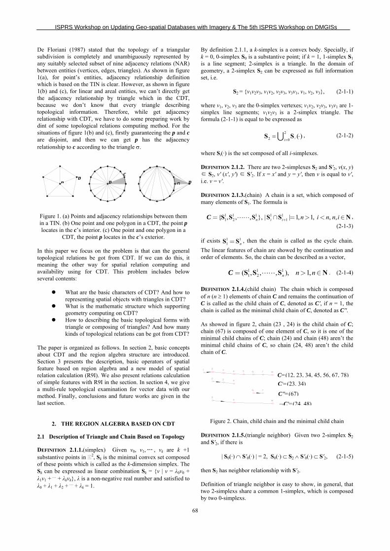
De Floriani (1987) stated that the topology of a triangular subdivision is completely and unambiguously represented by any suitably selected subset of nine adjacency relations (NAR) between entities (vertices, edges, triangles). As shown in figure 1(a), for point’s entities, adjacency relationship definition which is based on the TIN is clear. However, as shown in figure 1(b) and (c), for linear and areal entities, we can’t directly get the adjacency relationship by triangle which in the CDT, because we don’t know that every triangle describing topological information. Therefore, while get adjacency relationship with CDT, we have to do some preparing work by dint of some topological relations computing method. For the situations of figure 1(b) and (c), firstly guaranteeing the p and c are disjoint, and then we can get p has the adjacency relationship to c according to the triangle σ. Figure 1. (a) Points and adjacency relationships between them in a TIN. (b) One point and one polygon in a CDT, the point p locates in the c’s interior. (c) One point and one polygon in a
CDT, the point p locates in the c’s exterior. In this paper we focus on the problem is that can the general topological relations be got from CDT. If we can do this, it meaning the other way for spatial relation computing and availability using for CDT. This problem includes below several contents:
What are the basic characters of CDT? And how to representing spatial objects with triangles in CDT?
What is the mathematic structure which supporting geometry computing on CDT?
How to describing the basic topological forms with triangle or composing of triangles? And how many kinds of topological relations can be got from CDT?
The paper is organized as follows. In section 2, basic concepts about CDT and the region algebra structure are introduced. Section 3 presents the description, basic operators of spatial feature based on region algebra and a new model of spatial relation calculation (R9I). We also present relations calculation of simple features with R9I in the section. In section 4, we give a multi-rule topological examination for vector data with our method. Finally, conclusions and future works are given in the last section.
2. THE REGION ALGEBRA BASED ON CDT
2.1 Description of Triangle and Chain Based on Topology
DEFINITION 2.1.1.(simplex) Given v0, v1,… , vk are k +1 substantive points in 2, Sk is the minimal convex set composed of these points which is called as the k-dimension simplex. The Sk can be expressed as linear combination Sk = {v | v = λ0v0 + λ1v1 + … + λkvk}, λ is a non-negative real number and satisfied to λ0 + λ1 + λ2 + … + λk = 1.
By definition 2.1.1, a k-simplex is a convex body. Specially, if k = 0, 0-simplex S0 is a substantive point; if k = 1, 1-simplex S1 is a line segment; 2-simplex is a triangle. In the domain of geometry, a 2-simplex S2 can be expressed as full information set, i.e.
S2 = {v1v2v3, v1v2, v2v3, v3v1, v1, v2, v3}, (2-1-1)
where v1, v2, v3 are the 0-simplex vertexes; v1v2, v2v3, v3v1 are 1-simplex line segments; v1v2v3 is a 2-simplex triangle. The formula (2-1-1) is equal to be expressed as
22 0
( )ii== ⋅S S∪ , (2-1-2)
where Si(·) is the set composed of all i-simplexes. DEFINITION 2.1.2. There are two 2-simplexes S2 and S'2, v(x, y) ∈ S2, v' (x', y') ∈ S'2. If x = x' and y = y', then v is equal to v', i.e. v = v'. DEFINITION 2.1.3.(chain) A chain is a set, which composed of many elements of S1. The formula is
1 1 1 1 11 2 1{ , , , }, | | 1, 1, , ,n i i n i n n iS S S S S Ν+= ∩ = > < ∈C ,
(2-1-3) if exists 1 1
1 nS S= , then the chain is called as the cycle chain. The linear features of chain are showed by the continuation and order of elements. So, the chain can be described as a vector,
1 1 11 2( , , , ), 1,n n nS S S Ν= > ∈C . (2-1-4)
DEFINITION 2.1.4.(child chain) The chain which is composed of n (n ≥ 1) elements of chain C and remains the continuation of C is called as the child chain of C, denoted as C', if n = 1, the chain is called as the minimal child chain of C, denoted as C''. As showed in figure 2, chain (23 , 24) is the child chain of C; chain (67) is composed of one element of C, so it is one of the minimal child chains of C; chain (24) and chain (48) aren’t the minimal child chains of C, so chain (24, 48) aren’t the child chain of C.
Figure 2. Chain, child chain and the minimal child chain DEFINITION 2.1.5.(triangle neighbor) Given two 2-simplex S2 and S'2, if there is
| S0(·) ∩ S'0(·) | = 2, S0(·) ⊂ S2 ∧ S'0(·) ⊂ S'2, (2-1-5) then S2 has neighbor relationship with S'2. Definition of triangle neighbor is easy to show, in general, that two 2-simplexs share a common 1-simplex, which is composed by two 0-simplexs.
pp
p c
pσ
C=(12, 23, 34, 45, 56, 67, 78)C'=(23, 34)
¬C'=(24, 48)
C''=(67)

ISPRS Workshop on Updating Geo-spatial Databases with Imagery & The 5th ISPRS Workshop on DMGISs
69
In the vector algebra, a quantity completely specified by a magnitude and a direction as a vector, the 1-simplex (v1v2) is a simple vector. By the method of vector algebra, the (2-1-1) formula S2 is expressed as following form, S2 = {{(v1v2), (v2v3), (v3v1)}, {(v1v2), (v2v3), (v3v1)}, {v1, v2, v3}}.
(2-1-6) For the direction of simplex, there are following descriptions: the 0-simplex has arbitrary direction; the direction of 1-simplex (v1v2) is from v1 to v2 or from v2 to v1, but these directions are not equivalent. The direction of 2-simplex is defined as anticlockwise or clockwise. Every simplex can be confirmed by its vertexes, and then a 2-simplex can be equivalently expressed as the following algebra form,
S2 = ⟨v1v2v3⟩ ≡ ⟨v2v3v1⟩ ≡ ⟨v3v1v2⟩. (2-1-7) DEFINITION 2.1.6.(vector product in triangle) In S2, the vector product of vertex i (i = 1, 2, 3) is
×i = (vi-1vi) × (vivi+1) = |(vi-1vi)| |(vivi+1)|sinθ, θ ∈ (0, π) ∪ (π, 2π), (2-1-8)
where θ is the vector included angle of (vi-1vi) and (vivi+1), ×i is a vector value, which is perpendicular to the plane composed of (vi-1vi) and (vivi+1), and (vi-1vi), (vivi+1) with ×i forms the right-handed system. THEOREM 2.1.1. Given S2, the order of vertexes is anticlockwise or clockwise, if the value of ∃×i (i = 1, 2, 3) is more than 0 (> 0), the order of vertexes is anticlockwise, denoted as S+; if the value of ∃×i (i = 1, 2, 3) is less than 0 (< 0), the order of vertexes is clockwise, denoted as S-. (omitted)
(a) Positive vector product and vertices of triangulation anticlockwise ordering (b) Negative vector product and vertices
of triangulation clockwise ordering Figure 3. Relation of triangle’s vector product and vertices
ordering 2.2 Definition of CDT and Its Basic Characteristics
DEFINITION 2.2.1.(plane Voronoi diagram) Given 2, point set P♣ = {p1, p2,…, pn}, (3 ≤ n < ∞, pi ≠ pj, i ≠ j, i, j ∈ ),
V(pi) = {p | d(p, pi) ≤ d(p, pj), i ≠ j, i, j ∈ }, (2-2-1) the region defined by the formula (2-2-1) is called as Voronoi polygon of point pi. The Voronoi polygon set of all point p1, p2, …, pn in point set P is
V(P) = {V(p1), V(p2), …, V(pn)}, (2-2-2) the Voronoi polygon set make up of the plane Voronoi diagram of P.
♣In this paper is an assumption that P is non-collinearity point set.
DEFINITION 2.2.2.(DT) Given 2, point set P and V(P), the neighbor grid which results from the connection of points in P in condition of share Voronoi boundary is called Delaunay Triangulation (DT) of set P, denoted as D(P). If the Delaunay triangulation is applied to the chain structure set (C) and the Delaunay Triangulation remains the linear features of C, then this kind of Delaunay Triangulation is called as constrained Delaunay triangulation (CDT). THEOREM 2.2.1. D(P) is simplicial complex.
Proof. (1) If σn ∈ D(P), then any face of σn ∈ D(P). Given σn∈D(P), according to formula (2-1-2), σn = {S0(·),
S1(·), S2(·)}. ∵σn ∈ D(P), apparently there is the following formula, i.e. ∀Si(·) ⊂ σn ⇒ Si(·) ∈ D(P), i = 1, 2, 3. ∴if σn ∈ D(P), there exist any face of σn ∈ D(P), (1) is tenable.
(2) If σn, σk ∈ D(P), then σn ∩ σk is ∅ or common face. Exclusive method, assuming σn, σk ∈ D(P), then σn ∩ σk = ¬∅ (σn ≠ σk) has five cases, as showed in figure 3.
① σn, σk intersects at non-common face-point, as showed in figure 4(c). According to the definition 2.1.8, there is
(23) ⇒ (∃p, d(2, p) = d(p, 3)) ∧ (p = λ02 + λ13, λ0, λ1≥0, λ0 + λ1 = 1),
∵(243) is collinearity,∴exist d(2, p) = d(p, 3) < d(4, p) ⇔ p ⊂ V(2) ∧ p ⊂ V(3) ∧ p ⊂ V(4), i.e. p is the equal distance point of 2 and 3 and p is inside (4)V , this case is incompatible with definition 2.2.1.∴① is not tenable.
② σn, σk intersects at non-common face-line segment, as showed in figure 4(d). The case of ② is not tenable. The prove method is same to ①.
③ σn, σk intersects at non-common face-face, as showed in figure 4(e). (23) intersects with (64) at point p. According to definition 2.2.2, for the (23) and (64), there are individually
(23)⇒ (2, ) ( ,3)(2, ) ( ,3)(2, ) ( ,3)
p pp pp p
⎧ < ∨⎪⎪⎪⎪ = ∨⎨⎪⎪ >⎪⎪⎩
d dd dd d
(64)⇒ (6, ) ( , 4)(6, ) ( , 4)(6, ) ( , 4)
p pp pp p
⎧ < ∨⎪⎪⎪⎪ = ∨⎨⎪⎪ >⎪⎪⎩
d dd dd d
,
there are 1 13 3C C 9= cases can be divided into three catalogs, i.e.
{(<, <), (<, >), (>, <), (>, >)} ⇔ p exists inside of two different Voronoi polygons at the same time;
{(<, =), (>, =), (=, <), (=, >)} ⇔ p exists inside and boundary of two different Voronoi polygons at the same time;
{(=, =)} ⇔ necessarily exist (26), (24), (36) and (34). ∵ the conclusions of and are incompatible with ① ②
definition 2.2.1. The conclusion of is incompatible with③ (1), ∴ is not tenable.③ ∵ , and are all not tenable, ① ② ③ ∴(2) is tenable. (1) and (2) are tenable, theorem 2.2.1 is tenable.
(a) (b) (c) (d) (e)
Figure 4. Regular togetherness of triangles (a), (b) and the
irregular togetherness of triangles (c), (d), (e)
2−S
d
e f
4 5
6
2+S
a
b c
1 2
5
AB
AB
AB
1 2
3
4
5
AB
2
3
5
6
41A
B
1 2
3
4

ISPRS Workshop on Updating Geo-spatial Databases with Imagery & The 5th ISPRS Workshop on DMGISs
70
DEFINITION 2.2.3.(CDT) Given point set P, Delaunay triangulation D(P) and chain set C, if the circumcircle of one random triangle in D(P) doesn’t contain the point which is all visibility with the three vertexes of the triangle at the same time, the visibility is only on the condition that the chain pipj of the nodes pi, pj (pi, pj∈σ) doesn’t intersect with any segments in C (extreme end points excluded), then the D(P) is called as the constrained Delaunay triangulation of C, denoted as CD(P). COROLLARY 2.2.1. CD(P) is simplicial complex. (omitted)
C is described as the set of many chains, i.e.
C = {C1, C2, …, Cn}, n ≥ 1, n ∈ . (2-2-3) THEOREM 2.2.2. Given C1, C2 ⊂ C, C''i(ab) ∈ Ci, C''j(cd) ∈ Cj, ∃p satisfies 0 1 0 1 0 1
' ' ' ' ' '0 1 0 1 0 1
, , 0, 1
, , 0, 1
p
p
a b
c d
λ λ λ λ λ λ
λ λ λ λ λ λ
⎧ = + ≥ + = ∧⎪⎪⎨⎪ = + ≥ + =⎪⎩
, p doesn’t change the
continuation property of chain C''i, C''j.
Proof. Only prove that (ab) ⇔ (apb) and (cd) ⇔ (cpd) are all tenable. By the vector algebra method, ∵p satisfies the condition: ∴there is (ab) = (ap) + (pb) = (apb), ∴(ab) ⇔ (apb) is tenable. By the same way, (cd) ⇔ (cpd) is tenable. The theorem 2.2.2 is tenable. COROLLARY 2.2.2. C'' ∈ Ci ⊆ C, C'' 1 1 1
1 2( , , , )nS S S= , n
∈ , n ≥ 1, there is ∀ 1iS ∈ CD (P).
Proof. (1) C'' doesn’t intersect self, i.e. C'' = 1
1S . ∵CD(P)
is simplicial complex, ∴there is C'' = 11S ∈ CD(P).
(2) C'' intersects. According to theorem 2.2.2, there is C'' = 1 1 1
1 2( , , , )nS S S , n∈ , n≥1, and C'' remains its continuation
property. ∵∀ 1iS ∈ C'' all belong to the case (1), ∴there is
∀ 1iS ∈ CD (P). By summary, corollary 2.2.2 is tenable.
The constrained chain set C and node set P is showed in figure 5(a), D(P) and CD(P) are showed in figure 5(b), 5(c). The CD(P) completely remains the linear features of chain set C, but the D(P) partially lost the linear features of C, as showed as the dashed line region in figure 5(b). (a)Constrained chain set C and node set P (b) D(P) (c) CD(P)
Figure 5. Constrained effect to the Delaunay triangulation of chain structures
2.3 Reasoning of σ’S Classification and σ’S Lateral Characteristic In CDT
DEFINITION 2.3.1.(1-simplex’s type) The C is the set of chains, P is the set of boundary nodes in C. Cm, Cn is the chain (Cm, Cn ⊆ C); pm, pn are individually the set of nodes in Cm, Cn. ∀σ ∈ CD(P), p1, p2, p3 are the three vertexes of σ, if pi, pj (i ≠ j, i, j =
1, 2, 3) ∧ pi ∈ pm ∧ pj ∈ pn is tenable, then f(pi, pj) = 0; if pi, pj
(i ≠ j, i, j = 1, 2, 3) ∧ (pi, pj ∈ pm) is tenable, then f(pi, pj) = 1; specially, if pi, pj (i = j, i, j = 1, 2, 3) is tenable, then f(pi, pj) = 2. If the different types of the three edges are considered, the triangles can be divided into three categories. ∀σ ∈ CD (P), the absolute value of formula (2-2-4) can be used to distinguish these three kinds of triangle,
1 1 1 2 1 3
2 1 2 2 2 3
3 1 3 2 3 3
( , ) ( , ) ( , )( , ) ( , ) ( , )( , ) ( , ) ( , )
p p p p p pp p p p p pp p p p p p
⎡ ⎤⎢ ⎥= ⎢ ⎥⎢ ⎥⎣ ⎦
f f fT f f f
f f f
. (2-2-4)
By formula (2-2-4), can take out the following the 5 cases:
1
2 1 11 2 11 1 2
T⎡ ⎤⎢ ⎥= ⎢ ⎥⎢ ⎥⎣ ⎦
2
2 0 00 2 00 0 2
T⎡ ⎤⎢ ⎥= ⎢ ⎥⎢ ⎥⎣ ⎦
3
2 1 01 2 00 0 2
T⎡ ⎤⎢ ⎥= ⎢ ⎥⎢ ⎥⎣ ⎦
4
2 0 10 2 01 0 2
T⎡ ⎤⎢ ⎥= ⎢ ⎥⎢ ⎥⎣ ⎦
5
2 0 00 2 10 1 2
T⎡ ⎤⎢ ⎥= ⎢ ⎥⎢ ⎥⎣ ⎦
DEFINITION 2.3.2.(σ’s type) ∀σ∈CD(P), if the value of |detT| is 4, the three edges of the triangle come from the same chain structure (type α, denoted as σα); if the value of |detT| is 6, the two edges of the three edges of the triangle come from the two different chain structure and the other edge comes from the same chain structure (type β, denoted as σβ); if the value of |detT| is 8, the three edges of the triangle come from the three different chain structure (type γ, denoted as σγ). In CD (P), σ is relative to C. The vertices of σ come from C, more particularity, the vertices come from the chain Ci ⊆ C. Thus, for some chain Ci ⊆ C, the type of σ is exactly described as the constrained type by Ci.
DEFINITION 2.3.3.(decomposition of σ’s type and its algebra formula) If consider the constrained type of σ based on the 0-simplex, the σ, constrained chain Ci and constrained type of σ have the following relationships,
σα←Ci ⇔ σγ←Ci ∧ σγ←Ci ∧ σγ←Ci ⇔ α = γ + γ + γ, (2-2-5) σβ←Ci ⇔ σγ←Ci ∧ σγ←Ci ∧ σγ←Cj ⇔ β = γ + γ + γ', (2-2-6)
σβ←Ci ⇔ σβ←Ci ∧ σγ←Cj ⇔ β = β + γ', (2-2-7) expressly, σ didn’t make up of the chain Ci (Ci ⊆ C), denoted as σ↵Ci. DEFINITION 2.3.4.(σ’s direction) ∀σα, σβ ∈ CD(P), pi, pj (i ≠ j, i, j = 1, 2, 3) and f(pi, pj) = 0, the arrangement direction of σ’s vertexes is constrained by the direction of chain (pipj), denoted as
( )i jp pσ . The anticlockwise direction of σ is denoted as ⊗σ
and the clockwise direction of σ is denoted as σ , the formula is described as
dir(σ) = σ∗, ∗∈{⊗ , ⊙ }. (2-2-8) THEOREM 2.3.1 ∀σα, σβ ∈ CD(P), its vertexes are pi, pj, pk (i ≠ j ≠ k, i, j, k = 1, 2, 3) and f(pi, pj) = 1, if the arrangement of vertexes is anticlockwise, the pk locates at the left side of chain

ISPRS Workshop on Updating Geo-spatial Databases with Imagery & The 5th ISPRS Workshop on DMGISs
71
(pipj); if the arrangement of vertexes is clockwise, the pk locates at the right side of chain (pipj).
Proof. The anticlockwise arrangement of vertexes, according to theorem 2.1.1, there is ×i = (pipj) × (pipk) > 0, i.e. there is the included angle θ formed by vector (pipj) and vector (pipk), which is between 0 and π. ∵sinθ > 0 (0 < θ < π), ∴×i > 0, so pk locates at the left side of (pipj). By the same way, while arrangement of σ’s vertexes is clockwise, there are π < θ < 2π and ×i < 0, pk locates at the right side of vector (pipj). Theorem 2.3.1 is tenable. DEFINITION 2.3.5(f extension of σ’s adjacency) ∃σm, σn ∈ CD(P) ∧ σm ∩ σn = {p, p'}. If f(p, p') = 0, there is f 0 adjacency relationship between σm, σn, denoted as σm f 0σn; if f(p, p') = 1, there is f 1 adjacency relationship between σm, σn, denoted as σm f 1σn. DEFINITION 2.3.6(symmetry of σ’s adjacency) The f 0 adjacency relationship and f 1 adjacency relationship are symmetrical with each other, i.e. σm f iσn ↔ σn f iσm (i = 0, 1). DEFINITION 2.3.7(degree of σ’s adjacency) ∀σ ∈ D(P), the degree of σ’s adjacency is the number of edge in σ when the value of f is 0 or 1, the formula is
( ) , 0,1ii iσ = σ =
fdeg . (2-2-9)
DEFINITION 2.3.8(propagation characteristic of σ’s adjacency) ∃σk , σm, σn∈CD(P), if there is (σk f iσm) ∧ (σm f iσn) (i = 0, 1), there exists propagation f i (i = 0, 1) adjacency relationship between σk and σn, denoted as i
k nσ σ→f . DEFINITION 2.3.9(semi-plane of chain) The left semi-plane of vector (vivj) is l(vivj) = {p | (vivj) × (vip) > 0, p ∈ 2}, the right semi-plane of vector (vivj) is r(vivj) = {p | (vivj) × (vip) < 0, p ∈ 2}. For σβ←Ci, σα←Ci, if its arbitrary edge vivj (vivj ∈ σ) is the minimal child chain Ci'' of Ci, whether the location of σ relative to chain Ci is left or right can be directly confirmed by dir(σ). If σ←Ci can’t be directly confirmed, it doesn’t contain the minimal child chain Ci'' of Ci. The reasoning left or right locations of σ←Ci according to the above two kinds of σ combining with the adjacency and propagation characteristic f adjacency are the important base for the description of spatial objects in CDT, as showed in figure 6, there are three kinds of σ←Ci which need inference of its left or right property.
(a) σγ←Ci (b) σβ←Ci (vivj = ¬Ci'', vivj ∈ Ci ∩ σ) (c) σα←Ci (∀vivj = ¬Ci'', vivj ∈ Ci ∩ σ)
Figure 6. Three kinds of σ←Ci whose left-right property can’t be directly confirmed
For the σγ, because there is only one vertex coming from Ci, the confirmation of the left-right property of σγ is feasible on the
condition of the confirmation of the left-right property of the other two vertexes on the help of two f 0 adjacencies. COROLLARY 2.3.1.(f 0 including & approximating) For ∀σγ←Ci ∈ CD(P), ∃σβ←Ci, σ'β←Ci ∈ CD(P), if σγ←Ci satisfies
0 0( , ) ( , ) ( )
i i j i i j i i ii v v i v' v' j i' v v' '⊗ ⊗γ← β← γ← β← γ← β← β←σ σ ∧ σ σ ∧ = ∈σ ∩σ ∩σC C C C C C Cf f ,
then the σγ←Ci locates at the left side of chain Ci.
Proof. Considering there exist three states of angle θ = ∠vivjv'j, i.e.
(1) If 0 < θ < π, the left side of vector chain (vivj, vjv'j) is l(vivj) ∩ l(vjv'j).
∵θ < π, ∴v'j ∈ l(vivj). According to definition of semi-plane of chain, there is v'j ∈ l(viv'j), ∴v'j ∈ l(vivj) ∩ l(vjv'j). By the same way, there is vi ∈ r(v'jv'i), so there is vi ∈ l(v'iv'j). ∵vi ∈ l(vivj), ∴vi ∈ l(vivj) ∩ l(vjv'j). According to theorem 2.3.1, there are
( , )i ji v v⊗β←σ C
⇒ vk ∈ l(vivj), ( ' , ' )i ji v v' ⊗β←σ C
⇒ v'k ∈ l(v'iv'j).
And more according to theorem 2.2.1, σ, σ1 and σ2 regularly relate each other, ∴σ locates at the left side of Ci. As shown in figure 7(b).
(2) If π < θ < 2π, the left side of chain (vivj, vjv'j) is l(vivj) ∪ l(vjv'j).
According to definition of semi-plane of chain there is vi ∈ l(vivj) ∧ v'j ∈ l(v'iv'j). According to theorem 2.3.1, vk ∈ l(vivj) ∧ v'k ∈ l(v'iv'j), and more according to theorem 2.2.1, σ, σ1 and σ2 regularly relate each other; ∴σ locates at the left side of Ci. As shown in figure7(c).
(3) If θ = π, the proof same to (1). Summarily, corollary 2.3.1 is tenable. (a) Left and right semi-plane of chain (b) 0<θ <π (c) π<θ <2π Figure 7. σγ←Ci some side including & approximating corollary
based on f 0 adjacency COROLLARY 2.3.2. For ∀σγ←Ci ∈ CD(P), ∃σβ←Ci, σ'β←Ci ∈ CD(P), if σγ←Ci satisfies
0 0( , ) ( , ) ( )
i i j i i j i i ii v v i v' v' j i' v v' 'γ← β← γ← β← γ← β← β←σ σ ∧ σ σ ∧ = ∈σ ∩σ ∩σC C C C C C Cf f ,
then the σγ←Ci locates at the right side of chain Ci. (omitted)
COROLLARY 2.3.3.( 0→f including & approximating) For
∀σγ←Ci ∈ CD(P), ∃σβ←Ci, σ'β←Ci ∈ CD(P), if σγ←Ci satisfies 0 0
( , ) ( , ) ( )i i j i i j i i ii v v i v' v' j i' v v' '⊗ ⊗
γ← → β← γ← → β← γ← β← β←σ σ ∧ σ σ ∧ = ∈σ ∩σ ∩σC C C C C C Cf f ,
then the σγ←Ci locates at the left side of Ci.
Proof. The set of triangles which are propagated by the transfer from σγ←Ci to σβ←Ci and from σγ←Ci to σ'β←Ci is Σ. There exist two points λvk, λ'v'k (λ, λ' > 0) at the vector directions (vjvk) and (vjv'k), as shown in figure 8(b), constructing assistant triangle vjλ'v'kλvk, which satisfies below formula
∀p ∈ Σ → p ∈ vjλ'v'kλvk, p ∈ 2,
β, γ β, γ α, β β, γ
β, γ
¬Ci''
α, β α, β
α, β
¬Ci''¬Ci''
jv, 'j iv v iv
kvkv
1σ 2σ
σ
θ
'jv, 'j iv viv
kv kv
1σ 2σ
σ
θ
( )i jv vl
( )i jv vr

ISPRS Workshop on Updating Geo-spatial Databases with Imagery & The 5th ISPRS Workshop on DMGISs
72
construct assistant triangles again, as shown in figure 8(c), σ'1 = vivjλvk, σ'2 = v'iv'jλ'v'k, σ' = vjλ'v'kλvk, according to the corollary 2.3.1, σ' locates at the left side of Ci. ∵σ ⊂ σ', ∴σ locates at the left side of Ci. Corollary 2.3.3 is tenable.
(a) (b) (c) Figure 8. σγ←Ci some side including & approximating corollary
based on 0→f adjacency
COROLLARY 2.3.4. For ∀σγ←Ci ∈ CD(P), ∃σβ←Ci, σ'β←Ci ∈
CD(P), if σγ←Ci satisfies 0 0
( , ) ( , ) ( )i i j i i j i i ii v v i v' v' j i' v v' 'γ← → β← γ← → β← γ← β← β←σ σ ∧ σ σ ∧ = ∈σ ∩σ ∩σC C C C C C Cf f ,
then σγ←Ci locates at the right side of Ci.(omitted) COROLLARY 2.3.5. For ∀σγ←Ci ∈ CD(P), ∃σβ←Ci, σ'β←Ci ∈
CD(P), if σγ←Ci satisfies 0 0
( , ) ( , ) ( )i i j i i j i i ii v v i v' v' j i' v v' '⊗ ⊗
γ← β← γ← → β← γ← β← β←σ σ ∧ σ σ ∧ = ∈σ ∩σ ∩σC C C C C C Cf f ,
then σγ←Ci locates at the left side of Ci.
Proof. Given σγ←Ci arrives to ( , )i i jv' v'
⊗β←σ C
by n (n > 1)
times of propagation; σγ←Ci arrives to σ by one time of propagation on direction of
( , )i i jv' v'⊗β←σ C
. According to corollary
2.3.3, σ arrives to ( , )i i jv v
⊗β←σ C
by 2 times of propagation; σ arrives
to ( ' , ' )i i jv v
⊗β←σ C
by n-1 times of propagation, i.e. σ locates at the
left side of Ci. According to corollary 2.3.1, ( , )i i jv v
⊗β←σ C
, σγ←Ci
and σ satisfy the f 0 including & approximating, ∵σ locates at the left side of Ci. ∴σγ←Ci locates at the left side of Ci. The corollary 2.3.5 is tenable. THEOREM 2.3.2.(including & approximating theorem) For ∀σγ←Ci ∈ CD(P), if ∃σ'←Ci, σ''←Ci ∈ CD(P), they all locate the left (or right) side of chain Ci at the same time, if σγ←Ci satisfies
σγ←Ci fσ'←Ci ∧ σγ←Ci fσ''←Ci , f ∈ { f 0, 0→f },
then the σγ←Ci locates the left (or right) side of Ci . (omitted) For σβ←Ci(vivj = ¬C''i, vi, vj ∈ Ci ∩ σβ←Ci), according to formula (2-2-6), it is divided as σγ←Ci and σγ'←Ci. So, its left-right properties can be got by the same way as σγ←Ci. COROLLARY 2.3.6. For ∀σβ←Ci ∈ CD(P) ∧ (vivj = ¬C''i, vi, vj ∈ Ci ∩ σβ←Ci), if σγ←Ci or σγ'←Ci locates at the left (or right) side of chain Ci and σγ←Ci ∧ σγ'←Ci → σβ←Ci is tenable, then the σβ←Ci locates at the left (or right) side of Ci. (omitted) For the σα←Ci (∀vivj = ¬C''i, vi, vj ∈ Ci ∩ σα←Ci), it can be transformed as judge the left-right properties of σγ←Ci by the type decomposition method. COROLLARY 2.3.7. For ∀σα←Ci ∈ CD(P) ∧ (∀vivj = ¬C''i, vi, vj ∈ Ci ∩ σα←Ci), if ∀σγ ∈ σ ( | |
1i i i= α←∧ σ → σ Cσ , σi ∈ σ)
locates at the left (or right) side of chain Ci, then the σα←Ci locates at the left (or right) side of chain Ci. (omitted) COROLLARY 2.3.8. ∀σ←Ci ∈ CD(P) ∧ ∀ C''i ∉ σ←Ci , there is a set σ = {σ | σγ←Ci} after type decomposition of σ←Ci, if satisfies
(∀σγ←Ci ∈ σ) (σγ←Ci f σβ←Ci ∧ σγ←Ci f σ'β←Ci ∧ σβ←Ci , σ'β←Ci locate different side of chain Ci ∧σβ←Ci f 1 σ'β←Ci),
f ∈ { f 0, 0→f },
then the result of σγ←Ci ∩ Ci is the start node or end node of chain Ci.
Proof. (proof by contradiction) As shown in figure 9. Given σγ←Ci arrives to σβ←Ci by m (m > 0, m ∈ ) times of f adjacency propagation and arrives to σ'β←Ci by n (n > 0, n ∈ ) times of f adjacency propagation, then the set of triangles affected by the propagation constructs a region g, every triangle in the set has node v and region g contains node i.e. v ∈ σγ←Ci ∩Ci. According to the known conditions, there is σβ←Ci f 1 σ'β←Ci, i.e. v ∈ σβ←Ci ∩ σ'β←Ci. Assuming that v is not the start node or end node of Ci, there is a minimal child chain (v is a node of minimal child chain) of Ci certain cross region g. This conclusion is incompatible with the theorem 2.2.1 that triangles are regular togetherness in CDT, so the assumption is not tenable. Corollary 2.3.8 is tenable. If the start node and the end node of the chain is the same node, the chain is a cycle. Cycle is the special state of chain structure. The following sections prove the left-right relationship between σ and Ci on the case that Ci ⊆ C is directed cycle, given the ordering of cycle vertices is anticlockwise. Explicitly, the above definitions, theorems and corollaries are tenable on the case that Ci is directed cycle. As a special structure, the directed cycle partitions the 2-dimension space into two clear regions, i.e. the left side region of cycle and the right side region of cycle, and the left side region is a closure region. So, the including & approximating theorem for chain structure is reduced on the known conditions.
(a) The σγ←Ci arrives to σβ←Ci and σ'β←Ci. (b) The condition of
assumption Figure 9.
THEOREM 2.3.3.(reduced including & approximating theorem) Given cycle Ci ⊆ C, ∃σ←Ci locates at the left (right) side of Ci. For ∀σ'←Ci ∈ CD(P), if it satisfies
σ'←Ci f 0σ←Ci, then σ'←Ci and σ←Ci locate at the same side of cycle Ci. (omitted) COROLLARY 2.3.9. Given cycle Ci ⊆ C, ∃σγ←Ci, ∃σ'γ←Ci all locate at the left side of cycle Ci, for ∀σ↵Ci ∈ CD(P), if it satisfies
σ↵Ci f 0σγ←Ci ∧σ↵Ci f 0σ'γ←Ci, then σ↵Ci locates at the left side of cycle Ci.
v'i'
vj, v'iv
v v'k
σ1 σ2 σ
v'i vj, v'i v
v v'k
σ1 σ2 σ
v'i '
vj, v'i v
λvk λv'k σ'
σ'1
σγ
σβ
σβ′
v v g

ISPRS Workshop on Updating Geo-spatial Databases with Imagery & The 5th ISPRS Workshop on DMGISs
73
Proof. Given σγ←Ci = {v1, v2, v3}, σ'γ←Ci = { v'1, v'2, v'3}, v1, v'1 ∈ Ci, ∵σ↵Ci f 0σγ←Ci ∧ σ↵Ci f 0σ'γ←Ci, ∴σ↵Ci = { v2, v3, v'3} ∨ σ↵Ci = {v2, v3, v'2}. According to including & approximating theorem, for ∀v ∈ {v2, v3, v'2, v'3}, it locates at the left side of cycle Ci, ∴σ↵Ci locates at the left side of closure cycle Ci. Corollary 2.3.9 is tenable. COROLLARY 2.3.10. Given cycle Ci ⊆ C, ∃σ↵Ci ∈ CD(P), it locates at the left side of cycle Ci. For ∀σ'↵Ci ∈ CD(P), if it satisfies
σ'↵Ci f iσ↵Ci, i = 0, 1, then σ'↵Ci locates at the left side of cycle Ci.
Proof. (proof by contradiction) According to known condition σ'↵Ci f iσ↵Ci, there is that two vertexes of σ'↵Ci locate at the left side of Ci. Assuming that the third vertex of σ'↵Ci locates at the right side of cycle Ci, and then σ'↵Ci intersects with Ci certain. This conclusion is incompatible with that the CD(P) is simplicial complex, so the assumption is not tenable.∴ the third vertex of σ'↵Ci locates at the left side of Ci, i.e. σ'↵Ci locates at the left side of cycle Ci. The corollary 2.3.10 is tenable. The reasoning results of node structure, vector chain structure and directed cycle structure in CDT are showed in figure 10.
(a) CDT building on node structure, vector chain structure and directed cycle structure (b) Direct taking out the left and right side of vector chain structure (c) Taken left and right side of
chain by the including & approximating theorem (d) Triangles associating with start and end node of chain
(e) Direct taking out the left and right side of directed cycle structure (f) Taken left and right side of directed cycle by the reduced including & approximating theorem (g) Ensuring left
side of cycle ¬σ←Ci (h) Node and it associating with triangle set Figure 10. Reasoning and propagation of σ←Ci by triangle
neighbour
2.4 0-Simplex, 1-Simplex in CDT and the Basic Morphology of Σ
CDT is simplicial complex, in which can get structure relations base form from σ’s properties. Following we give three type of compositive relationships, i.e. node-node, node-chain and chain-chain.
2.5 Structure Description and Region Algebra Structure in CDT
In CDT, the triangle is the least unit for describing the chain structure, cycle structure and node structure. Every arbitrary chain, ring and node structure can be denoted as a set of triangle. According to the definition 2.3.4, structure can be described with the following formula,
σstr = {σα←str ∪ σβ←str ∪ σγ←str }. (2-5-1) However, formula (2-5-1) can’t exact describe the position and shape of str. Considering the own direction of str (0 dimension-arbitrary direction, 1 dimension-direction from start node to end node, 2 dimension-clockwise or anticlockwise direction), the direction of ∀σ∈σstr are affected by its own direction, i.e. the result of dir(σ) is clockwise or anticlockwise direction. According to the above definitions, theorems and corollaries, the chain structure σchain can be divided into three parts, i.e. the left side of chain, the right side of chain and the middle side of chain satisfied to corollary 2.3.8,
σchain = {σl(chain) ∪ σ r(chain) ∪ σ m(chain)}. (2-5-2) Because the ring structure can’t construct the middle triangle, formula (2-5-2) is reduced as the following formula,
σcycle = {σl(cycle) ∪ σ r(cycle)}. (2-5-3) For the independence vertex constructing the chain and cycle, formula (2-5-3) is transformed as formula (2-5-4),
σvertex = {σl(vertex)} ∨ {σr(vertex)} ∨ {σm(vertex)}. (2-5-4) THEOREM 2.5.1. σstr set associating with finite vertex structure in CDT consequentially is a closure region in 2.
Proof. σstr of independence vertex is composed of f 0 adjacency. The structure of chain and cycle takes out its left and right side based on σβ which contains minimal child chain and the including & approximating theorem to stipulate 1 dimension segment as an adjacency condition, which is progress of σβ extension with segment sharing. ∵ σ is the simplex in 2 dimension space and ∵ node is limited and ordered, ∴σstr set is a closure region in 2. DEFINITION 2.5.1. σstr set associating with a structure and representing closure region in 2 is named structure region. Structure set (SS) is transformed as structure region set (SRS) in CDT and there is the following relationship between SRS and CDT,
1 , card( ),ni i in== = ∈SRS SRS∪ σ σCDT ,(2-5-4)
considering family of sets Ξ = 2CDT, ∀ξ ∈ Ξ ∧ ξ ≠ {∅}, if ξ satisfied for the following condition,
card( ) 1 ( ( )
! , 0,1)
i
i
' ' is not tenable
at least ' ' is tenable i
ξ ξ ξ ξ
ξ ξ ξ→= ∨ ∀ ∈ ∀ ∈ ∨
∃ ∈ , =
ξ ξ ξ
ξ
f
f,
then the ξ is called the subject region of CDT, denoted as sξCDT ,
the set of all subject region of CDT is denoted as sΞCDT . If ξ satisfied into the following condition,

ISPRS Workshop on Updating Geo-spatial Databases with Imagery & The 5th ISPRS Workshop on DMGISs
74
card( ) 1 ( ! , 0,1)iat least ' ' is tenable iξ ξ ξ ξ= ∨∀ ∈ ∃ ∈ , =ξ ξ ξ f , then the ξ is called as the closure subject region of CDT (closure subject region). Clearly, every structure in CDT is a closure subject region. Thus, for the object structure, the entireness and part of object structure can be CDT described by use of
str
sΞσ.Constructing the following set,
F s= ΞCDT . (2-5-5)
Additionally, the F is the whole computing space. Thus the intersection operator (∩) can be used as the binary operator of F. Constructing the following mathematic structure,
RA = ⟨F, ∩, CDT, {∅}⟩. (2-5-6) THEOREM 2.5.2. RA is algebra structure.
Proof. (1) ∀ω, ω' ∈ F, ω ∩ ω' is significative. ω and ω'
express the whole or partial structure in CDT, the intersection operator (∩) for ω, ω' is valid.
(2) ∀ω, ω' ∈ F, ω ∩ ω' ∈ F. If ω ∩ ω' = ∅, ∵∅ ∈ F, ∴ω
∩ ω' ∈ F. If ω ∩ ω' = ¬∅, the result of intersection operator sure of the common subject region of ω and ω', given the result is ω*, there is ω*∈ Ξs
ω ∧ ω*∈ 'Ξsω , ∵ ',Ξ Ξs s
ω ω ∈ F, ∴there is
surly ω*∈ F. ∵∀ω ∈ F, there is CDT ∩ ω = ω ∧ ω ∩ CDT = ω, ∴CDT
is the unit element, and more ∵∅ ∩ ω = ∅ ∧ ω ∩ ∅ = ∅, ∴∅ is the zero element. So, RA is algebra structure. F denotes the region set of structure in CDT. So the above algebra is called as region algebra (RA). The forms of Region (subject region) are various and are equal with topology and algebra. The region is correlation. The region is not only the combination of topology unit and modal unit but also has spatial and algebraic characteristics. 3. SPATIAL RELATIONS CALCULATING BASED ON
RA
The spatial description method of geographic objects and the spatial relationship calculation method of spatial features are the spirit of GIS. The former is the base of the later that behaves as the computation processes in different mathematics space. The spatial relationship calculation can be analyzed based on the spatial description method of geographic features. The most popularity used model is the 9I model in the domain of spatial relationship calculation (Egenhofer and Herring 1991). According to the theory of unit structure (Corbett 1985), the 2-dimension feature is boundary by the 1-dimension and the 1-dimension feature is boundary by the 0-dimension in the 2-dimension Euclidean space 2. So, the boundary of spatial object is composed of 0-dimension points and 1-dimension segments. The boundary describes the position and shape of spatial object. In the 9I model, every entity is defined as three entities, an interior (○), a boundary (∂) and an exterior (-). Except the region held by the entity self and its boundary, the exterior of entity is filling all universe. When the universe is n
(n ≥ 2), the description of entity has continuous restriction,
which behaves that the description of single entity (i.e. interior, boundary or exterior) must depend on the other two entities. Zhilin Li (2000) has found that these three entities have linear relative relationship. In order to eliminate the continuous bondage in entity description, many researchers work hard in this domain. Chen Jun (2000) deflated the exterior as a limited area relative and defined the area as dependent entity by replacing the exterior with the Voronoi region of feature, but the interior and boundary still depend on each other; Zhilin Li (2000) described the entity in grid space 2 not in the Euclidean space 2, thus the three entities can be individually described as the set of grid unit. But from the math base for entity description, 2 can’t be replaced by 2 after all. The spatial relationship calculation can be analyzed from the geometric operation. The most important operation is intersection in order to distinguish the feature relationships, that is build up line intersection-based. Line intersection is a kind of graphics quantitative operation which needs complex computation and needs complex structure as the support. Therefore, researchers (Gold 1992, Chen 1998) proposed two problems: Whether the complex graphics operation (such as line intersection) can be replaced by comparison of simple characteristics in computing graphics relationship or not? Whether other spatial relationship can be got by using the support structure required by graphics operation or not? The two problems can be summarized as the qualitative and reasoning computation. They are the core ideas of the dynamic spatial relationship calculation. In the qualitative computation domain, many researches have been undertaken in order to resolve the adjacency spatial relationship computation by use of Voronoi diagram (Gold 1992, Okabe, Boots and Sugihara 1992, 1994 Chen 1998, Gahegan 2000). The adjacency spatial relationship computation is realized by judging whether the Voronoi feature’s regions exist the common boundaries or not. Because the Voronoi diagram is complete division structure to space, the share operation of Voronoi boundary is a typical geometry qualitative operation; in the domain of reasoning computation, Li and Chen (1998) proposed a 4 adjacency reasoning model based on Voronoi region which is an effective extend to resolve the question of adjacency spatial relationship computation by Voronoi diagram. The method used in the model is that the spatial relationship among objects is got by judging the relationship among Voronoi regions of object on the precondition of Voronoi region of object existence. 3.1 Description of Integrating Discrete and Continuous Spatial Object
The point, line and polygon features in 2 can be described by use of independent node, chain and ring structure in CDT with RA. Thus, the feature can be described as three independent entities, i.e. left (ωl), middle (ωm) and right (ωr).
THEOREM 3.1.1. The left set (ωl), middle set (ωm) and
right set (ωr) of spatial objects (pointR, lineR and polygonR) are all countable sets.
Proof. If the n(n is countable, n∈ ) nodes are considered as the generators, the Voronoi diagram of this generators is a set of n Voronoi regions. The set is a countable set and is a kind of division of space. ∵Voronoi diagram is dual with Delaunay triangulation each other, ∴Delaunay triangulation is sure of a countable set composed of many triangles, i.e. CDT. And more ∵∀σ ∈ ωl ⇒ σ ∈ CDT , ∴ωl ⊂ CDT . By the same way there is

ISPRS Workshop on Updating Geo-spatial Databases with Imagery & The 5th ISPRS Workshop on DMGISs
75
ωm ⊂ CDT and ωr ⊂ CDT . ∵CDT is a countable set, ∴ωl, ωm
and ωr are all countable sets. Theorem 3.1.1 is tenable.
COROLLARY 3.1.1. The left (ωl), middle (ωm) and right (ωr) of spatial objects (pointR, lineR and polygonR) are all partial relative regions.
Proof. According to theorem 3.1.1, the left, middle and right set are all countable sets and there is ωl ∪ ωm ∪ ωr ⊆ CDT, i.e. ωl ∪ ωm ∪ ωr is the subset of CDT. And more ∀σ∈ωl ∪ ωm ∪ ωr, σ is all relative to the spatial objects in 2, i.e. the nodes of σ result from the spatial object. In summary, the left (ωl), middle (ωm) and right (ωr) of spatial objects are all partial relative regions.
THEOREM 3.3.2. The left set (ωl), middle set (ωm) and
right set (ωr) of spatial objects (pointR, lineR and polygonR) are reverted as the corresponding structures (point, line and polygon) in 2.
Proof. Polygon object is ωl ∪ ωr, given operation seg(σl,
σr)(σl ∈ ωl, σr ∈ ωr) is the segment used for seeking the f 1 adjacency between σl and σr, thus the segment is sure of the part of boundary of polygon object and its two extreme points are sure of the boundary node of the polygon object. Given the segment set sought by seg operation is S, then S can be sought by the following formula,
| | | |1 1 ( , ), ,l r l r l l r r
i j σ σ σ σ= == ∈ ∈S ∪ ∪ segω ω ω ω , (3-1-1)
∵CDT is a kind of spatial division, ∴the boundary of the area object can be got by linking the segments in S on the condition of the same node order, and i.e. this is the cycle structure in 2. By the same way, the case of line object and point object can be proved. Theorem 3.3.2 is tenable. According to the theorem 3.3.2, the discrete definition of spatial object completely remains its continuation property in 2, that is to say, it remains its basic position and shape of in 2. CDT is the common way to observe the raster and vector characteristics of spatial objects. DEFINITION 3.1.1.(basic definition of spatial object in CDT) the spatial objects (point, line and polygon) in 2 can be denoted as the pointR, lineR and polygonR in CDT and there is the following corresponding relationship,
R - -( ) ( ) ( ) ( )( ) ( ) ( )
def
C C C Cpolygon poly poly poly∂ ∂⇔ + + ⇔ + ∪ +ω σ ω σ σ ω σr l r l,(3-1-2)
R - -( ) ( ) ( ) ( ) ( ) ( )( ) ( ) ( )
def
C C C C C Cline line line line∂ ∂⇔ + + ⇔ ∪ ∪ + + ∪ω σ σ σ ω σ ω σ σl r m m l r,(3-1-3)
R - -( ) ( ) ( )def
C C Cpoint point point point∂ ∂← ← ←⇔ + + ⇔ + +ω σ ω σ ω σ . (3-1-4)
3.2 Basic Operators and the Computation Model of Spatial Relationship
Intersection operation “∩” is the exclusive 2-tuple operator in the region algebra structure. Based on the intersection operator, the region modality operator (τ) applied to the spatial object can be got. The “∩” and “τ” are the basic operators for relationship calculation.
Symbol Definition Computation result ( , )A B∩ ω ω
Given ,A Bω ω are
two subject regions, then there is the following formula, ( , )
{ | }
A B
A Bσ σ σ
∩ =
∈ ∧ ∈
ω ω
ω ω.
{ ,{ }}A B
s s∅ ∈Ξ ∧ ∈Ξω ωξ | ξ ξ
( )τ ω Compute the basic modality of subject region ω.
{ , nen,nan,ndn,nicl,nicr,nic,noc,nacl,nacr,ndc,chec,cec,cnc,cicl,cicr,cic,ctc,cac,cdc}
= ∅re
( ) 2τ ⊂ reω
Table 3.2. Symbols, definitions and computing results of the
basic operators
DEFINITION 3.2.1. The modality operation of subject region (∩τ) is the composite operation of “∩” and “τ”, its formula is,
∩τ(ωA, ωB) = τ(∩(ωA, ωB)) = τ(ωA ∩ ωB). (3-2-1) Adbelmoty (1995) proposed a generalized intersection model applied to describe the spatial relationship. Firstly, it decomposes the spatial object and region space as typical subsets. Secondly, describes the spatial relationships based on the intersection of these subsets. Given σ is a spatial object and {σ1, σ2,…, σn} is its subsets, then there is 1
mi i=∪σ = σ , the
complement set of σ is σ-1
nj m j= += ∪ σ , the spatial reverse
located by spatial object is Σ, then there is Σ = σ ∪ σ-. By decomposing the spatial object based on union, the relationship between two spatial objects can be defined as the following formula,
=1 =1
1 1 1 2 1 2 1
( ) = ( ) ( ) =
( , , , , , , )
m ni i j j
n m n
R ' ' '
' ' ' ' '
, = ∩ ∩
∩ ∩ ∩ ∩ ∩
∪ ∪σ σ σ σ σ σ
σ σ σ σ σ σ σ σ σ σ,
where σi ∩ σ'j may fetch ∅ or ¬∅, the intersection may be expressed with a m× n matrix. By different division strategy of spatial object, generalized intersection model can describe the spatial relationship among complex spatial objects. According to the generalized intersection model and the basic definition of spatial object (definition 3.1.1), a spatial relationship calculation model is established on the following conditions: the modality operation of subject region is regarded as the basic operation and the result resulted from the intersection each other of the three entities (exterior, boundary and interior) of the two spatial objects. The formula of this model is denoted as a 3× 3 matrix, as showed in formula 3-2-2, which named as region nine intersection model (R9I).
R9I( , )A B A B A B
A B A B A B
A B A B A B
τ τ τ
τ τ τ
τ τ τ
Α Β
− − − ∂ −
∂ − ∂ ∂ ∂
− ∂
⎡ ⎤∩ ∩ ∩⎢ ⎥= ∩ ∩ ∩⎢ ⎥⎢ ⎥∩ ∩ ∩⎣ ⎦
ω ω ω ω ω ωω ω ω ω ω ωω ω ω ω ω ω
. (3-2-2)
According to the result of subject region modality computation, the computation results of R9I model can be classified as follow: if every unit value of R9I is single type, i.e. re = {∅} ∨ |re| = 2, the type is single modality type; if |re| > 2, the type is duplicate modality type.

ISPRS Workshop on Updating Geo-spatial Databases with Imagery & The 5th ISPRS Workshop on DMGISs
76
3.3 Computing Spatial Relations among Simple Objects by R9I
No Legend Value of R9I Semantics 1
∅ ∅ ∅⎡ ⎤⎢ ⎥∅ ∅ ∅⎢ ⎥⎢ ⎥∅ ∅ ∅⎣ ⎦
disjoint
2
nan nan nannan nan nannan nan nan
⎡ ⎤⎢ ⎥⎢ ⎥⎢ ⎥⎣ ⎦
adjacency
3
nen nen nennen nen nennen nen nen
⎡ ⎤⎢ ⎥⎢ ⎥⎢ ⎥⎣ ⎦
equal
Table 3.3.1. Relationships of pointR&pointR
No Legend Value of R9I Semantics 1
∅ ∅ ∅⎡ ⎤⎢ ⎥∅ ∅ ∅⎢ ⎥⎢ ⎥∅ ∅ ∅⎣ ⎦
disjoint
2
nic nicnic nicnic nic
∅⎡ ⎤⎢ ⎥∅⎢ ⎥⎢ ⎥∅⎣ ⎦
contain
3
noc nen nocnoc nen nocnoc nen noc
⎡ ⎤⎢ ⎥⎢ ⎥⎢ ⎥⎣ ⎦
boundary
Table 3.3.2. Relationships of pointR&lineR
No Legend Value of R9I Semantics 1
∅ ∅ ∅⎡ ⎤⎢ ⎥∅ ∅ ∅⎢ ⎥⎢ ⎥∅ ∅ ∅⎣ ⎦
disjoint
2
nacr nacrnacr nacrnacr nacr
∅⎡ ⎤⎢ ⎥∅⎢ ⎥⎢ ⎥∅⎣ ⎦
adjacency
3
nicr nic niclnicr nic niclnicr nic nicl
⎡ ⎤⎢ ⎥⎢ ⎥⎢ ⎥⎣ ⎦
boundary
4
nacl naclnacl naclnacl nacl
∅⎡ ⎤⎢ ⎥∅⎢ ⎥⎢ ⎥∅⎣ ⎦
contain
Table 3.3.3. Relationships pointR&polygonR
No Legend Value of R9I Semantics 1
∅ ∅ ∅⎡ ⎤⎢ ⎥∅ ∅ ∅⎢ ⎥⎢ ⎥∅ ∅ ∅⎣ ⎦
disjoint
2
cac nac cacnac nancac cac
⎡ ⎤⎢ ⎥∅⎢ ⎥⎢ ⎥∅⎣ ⎦
adjacency
3
cic cic
cic cic
∅⎡ ⎤⎢ ⎥∅ ∅ ∅⎢ ⎥⎢ ⎥∅⎣ ⎦
intersection
4
cnc noc cncnoc nencnc ccn
⎡ ⎤⎢ ⎥∅⎢ ⎥⎢ ⎥∅⎣ ⎦
meet at ends
5 cicl(r) nicl(r) cicl(r)nac nan nac
cicl(r) nicr(l) cicl(r)
⎡ ⎤⎢ ⎥⎢ ⎥⎢ ⎥⎣ ⎦
meet at one end and other
middle 5 cec nic cec
nic niccec nic cec
⎡ ⎤⎢ ⎥∅⎢ ⎥⎢ ⎥⎣ ⎦
overlap
6 cec cec
cec cec
∅⎡ ⎤⎢ ⎥∅ ∅ ∅⎢ ⎥⎢ ⎥∅⎣ ⎦
1D meet
7 cec cecnoc noccec cec
∅⎡ ⎤⎢ ⎥∅⎢ ⎥⎢ ⎥∅⎣ ⎦
contain
8 cec noc cecnoc nen noccec noc cec
⎡ ⎤⎢ ⎥⎢ ⎥⎢ ⎥⎣ ⎦
equal
Table 3.3.4. Relationships of lineR&lineR
No Legend Value of R9I Semantics 1 ∅ ∅ ∅⎡ ⎤
⎢ ⎥∅ ∅ ∅⎢ ⎥⎢ ⎥∅ ∅ ∅⎣ ⎦
disjoint
2 cac nac caccac nac cac
⎡ ⎤⎢ ⎥⎢ ⎥⎢ ⎥∅ ∅ ∅⎣ ⎦
adjacency
3 cac cacnacl naclcac cac
∅⎡ ⎤⎢ ⎥∅⎢ ⎥⎢ ⎥∅⎣ ⎦
contain
4 cicr cic ciclnacl nacl
cicr cic cicl
⎡ ⎤⎢ ⎥∅⎢ ⎥⎢ ⎥⎣ ⎦
entry/go out
5 cicr cic ciclnicr nicrcicr cic cicl
⎡ ⎤⎢ ⎥∅⎢ ⎥⎢ ⎥⎣ ⎦
half-cross
6 cicr cic ciclnacr
cicr cic cicl
⎡ ⎤⎢ ⎥∅ ∅⎢ ⎥⎢ ⎥⎣ ⎦
cross
7 ctc ctc nicl
ctc ctc nicl
⎡ ⎤⎢ ⎥∅ ∅ ∅⎢ ⎥⎢ ⎥⎣ ⎦
0-D meet
8 cec cec cec
cec cec cec
⎡ ⎤⎢ ⎥∅ ∅ ∅⎢ ⎥⎢ ⎥⎣ ⎦
1-D meet
Table3.3.5. Relationships of lineR&polygonR
No Legend Value of R9I Semantics 1
∅ ∅ ∅⎡ ⎤⎢ ⎥∅ ∅ ∅⎢ ⎥⎢ ⎥∅ ∅ ∅⎣ ⎦
disjoint
2
cac caccac cac
∅⎡ ⎤⎢ ⎥∅⎢ ⎥⎢ ⎥∅ ∅ ∅⎣ ⎦
adjacency
3
ctc ctc niclctc ctc niclnicl nicl
⎡ ⎤⎢ ⎥⎢ ⎥⎢ ⎥∅⎣ ⎦
0-D meet
4
cnc cecr cecrcnc cec cecrcecl cecl
⎡ ⎤⎢ ⎥⎢ ⎥⎢ ⎥∅⎣ ⎦
1-D meet

ISPRS Workshop on Updating Geo-spatial Databases with Imagery & The 5th ISPRS Workshop on DMGISs
77
5
cnc cicr cnccicr cic ciclcnc cicl cnc
⎡ ⎤⎢ ⎥⎢ ⎥⎢ ⎥⎣ ⎦
intersect
6
cac caccac cac cac
∅ ∅ ∅⎡ ⎤⎢ ⎥∅⎢ ⎥⎢ ⎥⎣ ⎦
contain
Table 3.3.6. Relationships of polygonR&polygonR
4. EXAMPLE
Multi-topological rules examination for vector data is a new requirement for GIS data product. In general, for different type of vector data which is independently organized and stored as a layer form, current GIS software provides the topological rules for checking errors included in one layer or between two layers. For example in Arc/Info, the “Must No Overlap” rule is used for checking a polygon feature must not overlap another polygon feature from the same layer, the “Boundary Must Be Covered By” rule is used for checking the boundaries of polygon feature from one layer must be covered by line features of another layer. However, every time only use one rule to the examination work.
With the method proposed in this paper, we can use multi-
rule. As shown in figure 11(a), (b), there are parts of block map and street map of Beijing and its CDT. The multi-rule includes three rules:
The “Must No Overlap” rule for block map not self-intersecting.
The “Must No Intersect” rule for the block map not intersects with the street map.
The “Adjacency” rule for every street must adjacency at least one block.
The topological errors by above multi-rule are shown in figure 11(c) and (d).
(a) Parts of block map and street map in Beijing
(b) The CDT of (a)
(c) Two blocks intersect (d) One street intersects with a block Figure 11. Example data and it CDT
5. CONCLUSION AND FUTURE WORKS
This work proposes a description method of 2D spatial object based on CDT which integrates continuous method and discrete method together. Based on the set theory, the subject region and computation space in CDT is defined. Additionally, the region algebra structure applied to compute spatial relationship is established on the base of intersection operation. By judging the modality of result set (subject region) of intersection among the three hefts of spatial object, the spatial relationship computation model-R9I is established. By R9I, the 32 kinds of spatial relationship among simple objects is distinguished each other. The future works can be summarized as following aspects:
(1) The modality of surface features (spatial graphics) is one of important research subjects in the spatial relationship domain. The understanding to real world always starts from the individuals. However, the research on spatial relationship directly focuses on the relationship among individuals not the individual. For instance, “query which circular buildings are adjacent with a road” can’t get the correct results by current spatial relationship theory. The constrained Delaunay triangulation division of spatial graphics is another important way to observe and analyze its modality. The figure 11 shows the knaggy characteristics of graphics, the exterior of convex polygon only contains β-triangle and γ-triangle. But the exterior of concave polygon also contains α-triangle.
(2) The computing of adjacency spatial relationship. The nature adjacency spatial relationship defined by Voronoi diagram of spatial objects is a special spatial relationship. It exits among the discrete spatial objects. However, the object exploration based on the spatial relationship always uses the intersection as the basic way. So, the expression method and index structure of adjacency region among spatial objects on the base that the Dalaunay triangulation is the base structure should be focused on. Then the adjacency spatial relationship can be detected by combining the line intersection operation in

ISPRS Workshop on Updating Geo-spatial Databases with Imagery & The 5th ISPRS Workshop on DMGISs
78
the practical GIS application environment with the Dalaunay triangulation.
(a) Convex polygon and its σβ, γ at right side (b) Concave
polygon and its σα at right side Figure 11. Observing the knaggy characteristics of polygon by
its σ
(3) The computing of spatial relationship among complex objects. The spatial object has the continuous (vector) and discrete (grid) characteristics at the same time in case that the spatial objects are described by the method based on CDT. The vector-grid characteristic of Delaunay triangulation should be further rooted in order to describe the complex spatial objects and compute the relationship among the complex objects by Delaunay triangulation.
(4) The thinking in λ. Whether 3 3
0 0{ | 0, 1}i
n i i ii iaσ λ λ λ
= == ≥ =∑ ∑ can be used to express the
complex-tetrahedroid in 3 or not; whether the method in 2 can be generalized to 3 or not in order to solve the description of 3D spatial objects and compute their spatial relationship?
ACKNOWLEDGEMENT
The work described in the paper was substantially supported by a grant the National Science Foundation of China under research grant No. 40337055 and 40301042.
REFERENCES
AI, T., and GUO, R., 2000, A constrained Delaunay partitioning of areal objects to support map generalization. Journal of WTUSM, 25, 35-41. (in Chinese). CHEN, J., 2002, Voronoi-based dynamic spatial data model. Beijing: Publishing house of Surveying and Mapping (in Chinese). CHEN, J., CUI, B.L., 1997, Using Voronoi approach of developing topological functions in MapInfo. Journal of WTUSM, 22, 195-200. (in Chinese). CHEN, J., ZHAO, R., LI, Z., 2004, Voronoi-based K-order neighbor relations for spatial analysis. ISPRS Journal of Photogrammetry and Remote Sensing, 59, 60-72. CORBELT, J., 1985, A general topological model for spatial reference. U. S. Census. DE FLORIANI, L., 1987, Surface representations based on triangular grids. The Visual Computer, 3,27-50. DE FLORIANI, L., and PUPPO, E., 1987, Constrained Delaunay triangulation for multiresolution surface description. In
proceedings of the 9th International Conference on Pattern Recognition, Rome, November 566-569. EGENHOFER, M. J., and HERRING, J., 1991, Categorizing binary topological relationships between regions, lines, and points in geographic databases, Technical Report, Department of Surveying Engineering, University of Maine. GAHEGAN, M., LEE, I., 2000, Data structures and algorithms to support interactive spatial analysis using dynamic Voronoi diagrams. Computers, Environment and Urban Systems, 24, 509-537. GOLD, C. M., 1991, Problems with handling spatial data—the Voronoi approach. CISM Journal ACSGC, 45, 65-80. GOLD, C. M., 1992, Problems with handling spatial data-The Voronoi approach. CISM Journal, 45, 65-80. GOLD, C. M., and EDWARDS, G., 1992. The Voronoi spatial data model: 2d and 3d applications in image analysis. ITC Journal, 1, 11-19. GOOLDCHILD, M. F., 1992, Geographical data modeling. Computers and Geosciences, 18, 401-408. JONES, B., and WARE, J. M., 1998, Proximity search with a triangulated spatial mode. The Computer Journal, 41, 71-83. JONES, C. B., and ABRAHAM, I. M., *** Design considerations for a scale-independent cartographic database. In Proceedings of the 2nd International Symposium on Spatial Data Handling, Seattle, Washington, July, International Geographical Union, 384-398. JONES, C. B., and ABRAHAM, I. M., 1987, Line generalization in a global cartographic database. Cartographica, 24, 32-45. JONES, C. B., BUNDY, G. L., and WARE, J. M., 1995, map generalization with a triangulated data structure. Cartography and GIS, 22, 317-331. JONES, C. B., BUNDY, G. L., and WARE, J. M., 1995, Map generalization with a triangulated data structure. Cartography and GIS, 22, 317-331. LI, C., CHEN, J., 1998, Spatial adjacency query based on Voronoi diagram. Journal of Wuhan Technical University of Surveying and Mapping, 23, 128-131. (in Chinese). LI, D., LI, Q., 1997, Study on a hybrid data structure in 3D GIS. Acta Geodaetica et Catographica Sinica, 23,128-133. (in Chinese). LI, J., ZHAO, R., and CHEN, J., 2006, Queries of nature neighbor objects on UnitsDelaunay structure in spatial database. In Geoinformatics 2006: Geospatial Information Science, Porc. of SPIE Vol. 6420, 642004. Li, Z., Li., Y., and Chen, Y., 2000, Basic topological models for spatial entities in 3-Dimensional Space. GeoInformatica, 4, 419-433.
LIN, J., 1998, Basic topology. Beijing: Science Publishing House, (in Chinese).

ISPRS Workshop on Updating Geo-spatial Databases with Imagery & The 5th ISPRS Workshop on DMGISs
79
MCCULLAGH, M. J., and ROSS, C. G., 1980, Delaunay triangulation of a random data set for isarithmic mapping. Cartographic, 17, 93-99. OKABE, A., BOOTS, B. N., and SUGIHARA, K.,1994, Nearest neighborhood operations with generalized Voronoi diagram a review. International Journal of Geographical Information Systems, 8, 43-71. OKABE, A., BOOTS, B., and SUGIHARA, K., 1992, Spatial tessellations: concepts and applications of Voronoi diagrams (2nd Edition). John Wiley and Sons. PREPARATA, F. P., and SHAMOS, M. I., 1988, Computational geometry. Texts and Monographs in Computer Science. Springer-Verlag, New York. SIBSON, R., 1978, Locally equiangular triangulations. Computer J, 21,243-245.
WARE, J. M., and JONES, C. B., 1992, A multiresolution topographic surface database. International Journal of Computer and Information Science, 6, 479-496. WARE, J. M., JONES, C. B., and BUNDY, G. L., 1997, A triangulated spatial model for cartographic generalization of areal objects. In: Kraak M J, Molenaar M eds, Advance in GIS Research II (the 7th Int. Symposium on Spatial Data Handling). London: Taylor & Francis, 173-192. Wu, H., 1997, Organization and procession of spatial data in GIS. Beijing: Publishing house of Surveying and Mapping, (in Chinese). WU, L., and SHI, W., 2003, Principles and algorithms of GIS. Beijing: Science Publishing House (in Chinese).