calcul connection in scia.pdf
TRANSCRIPT

7/23/2019 Calcul Connection in Scia.pdf
http://slidepdf.com/reader/full/calcul-connection-in-sciapdf 1/89

7/23/2019 Calcul Connection in Scia.pdf
http://slidepdf.com/reader/full/calcul-connection-in-sciapdf 2/89
All information in this document is subject to modification without prior notice. No part or this manualmay be reproduced, stored in a database or retrieval system or published, in any form or in any way,electronically, mechanically, by print, photo print, microfilm or any other means without prior writtenpermission from the publisher. SCIA is not responsible for any direct or indirect damage because ofimperfections in the documentation and/or the software. © Copyright 2013 SCIA. All rights reserved.

7/23/2019 Calcul Connection in Scia.pdf
http://slidepdf.com/reader/full/calcul-connection-in-sciapdf 3/89
Scia Engineer
Contents
1. Introduction ........................................................................................................................ 5
2. Creation of a small example in Scia Engineer ................................................................ 6
2.1. Modeling the example ............................................................................................................ 6
2.2.
Input of the connection .......................................................................................................... 7
2.3. Check and update of stiffness ............................................................................................... 9
2.4. Connection does not satisfy the checks ............................................................................ 11
3. Possible connections in Scia Engineer ......................................................................... 12
4. Check of the connection (unity check) .......................................................................... 13
4.1. General data .......................................................................................................................... 13
4.2. Column web panel in shear ................................................................................................. 15
4.3. Column web in compression ............................................................................................... 16
4.4. Beam flange and web in compression................................................................................ 17
4.5. Resistance of the T-stub ...................................................................................................... 17
4.5.1. Principle of a T-stub calculation .................................................................................... 17
4.5.2.
Bolts info ....................................................................................................................... 20
4.5.3. Column flange ............................................................................................................... 20
4.5.4. End plate ....................................................................................................................... 27
4.5.5. Potential tension resistance for each bolt row .............................................................. 35
4.6. Calculation of MRd................................................................................................................ 35
4.7. Calculation of NRd ................................................................................................................ 38
4.8. Calculation of VRd ................................................................................................................ 40
4.9. Unity checks .......................................................................................................................... 41
4.9.1. Influence of the normal force ........................................................................................ 41
4.9.2. General unity checks .................................................................................................... 42
5. Stiffness of the connection ............................................................................................. 43
5.1.
The Moment-Rotation characteristic ................................................................................... 43 5.2. Calculation of the stiffness .................................................................................................. 46
5.2.1. General formulas .......................................................................................................... 46
5.2.2. Calculation of the stiffness in detail .............................................................................. 48
5.3. The classification on stiffness ............................................................................................. 53
5.4. Transferring the joint stiffness to the analysis model ...................................................... 56
5.5. The required stiffness .......................................................................................................... 59
6. Calculation of welds ........................................................................................................ 63
6.1. Default method ...................................................................................................................... 63
6.2. Calculation of af ..................................................................................................................... 64
6.3. Calculation of aw.................................................................................................................... 65
6.4. Calculation with the internal forces .................................................................................... 66
7.
Ductility class ................................................................................................................... 67
7.1. Ductility classes .................................................................................................................... 67
7.2. Ductility classification for bolted joints .............................................................................. 67
7.3. Ductility classification for welded joints ............................................................................ 68
8. Extra options in Scia Engineer ....................................................................................... 69
8.1. RHS beam .............................................................................................................................. 69
8.2. Column in minor axis configuration ................................................................................... 69
8.3. Base plate connections: shear iron, flange wideners ....................................................... 70
8.4. Extra options for the calculation of connections .............................................................. 70
8.4.1. Copy of connections ..................................................................................................... 71
8.4.2. Multiple check of connections ....................................................................................... 71
8.4.3.
Expert system ............................................................................................................... 72 8.4.4. The use of 4 bolts / row ................................................................................................ 73
8.4.5. Monodrawings............................................................................................................... 74

7/23/2019 Calcul Connection in Scia.pdf
http://slidepdf.com/reader/full/calcul-connection-in-sciapdf 4/89
8.4.6. Options in the properties window.................................................................................. 76
9. Welded connections ........................................................................................................ 77
10. Pinned joints ..................................................................................................................... 82
10.1. Welded fin plate connection ........................................................................................... 82
10.2. Bolted fin plate connection ............................................................................................. 85
10.3. Bolted cleat connection .................................................................................................. 87
10.4.
Flexible end plate connection ........................................................................................ 88
References and literature .......................................................................................................... 89

7/23/2019 Calcul Connection in Scia.pdf
http://slidepdf.com/reader/full/calcul-connection-in-sciapdf 5/89
Scia Engineer
1. Introduction
This course will explain the calculation of steel connections in Scia Engineer following the EN 1993-1-8: Design of steel structures – Part 1-8: Design of joints.
Most of the options in the course can be calculated/checked in Scia Engineer with the Steel edition.
For some supplementary checks an extra module (or edition) is required, but this will always beindicated in those paragraphs.
The design methods for connection design are explained. More details and references to the appliedarticles can be found in (Ref.[2]).
The following chapters are valid for the bolted and welded column-beam joints. The design methods forthe beam-column joints are principally for moment-resisting joints between I or H sections in which thebeams are connected to the flanges of the column. In this document we will describe the totalprocedure for this type of connection. The other connection types can be found at the end of this
document.

7/23/2019 Calcul Connection in Scia.pdf
http://slidepdf.com/reader/full/calcul-connection-in-sciapdf 6/89
2. Creation of a small example in Scia Engineer
2.1. Modeling the example
First in this chapter a small example in Scia Engineer will be shown. Afterwards all principles and thetheoretical background will be explained in the next chapter.
Create a new project in Frame XYZ, activate the material Steel S235 and activate the functionalityFrame rigid connections.
The following options are available for connections:
Connection Modeller: With this option you can only model a connection and not run acalculation of a connection. If you want to calculate the connection,don’t activate this functionality!
Frame rigid connections: Calculation of bolted and welded (rigid and semi-rigid) connections.
Fame pinned connections: Calculation of pinned connections
Grid pinned connections: Calculation of pinned connection in the horizontal plane
Bolted diagonal connections: Calculation of bolted diagonals
Expert system: Use a library with default connections in Scia Engineer or add your
own connections to this library
Connection monodrawings: Make some nice overview drawings of your connection(s)

7/23/2019 Calcul Connection in Scia.pdf
http://slidepdf.com/reader/full/calcul-connection-in-sciapdf 7/89
Scia Engineer
Choose for the column a HE140B profile and for the beam an IPE220 with the following geometry andthe only load is a line load of 5 kN/m on the beam (no self weight).
2.2. Input of the connection
Calculate the model and go to the Steel menu.
The beam is connected with the strong axis of the column, so we choose in this menu for “Connections-> Frame bolted/welded-strong axis”. Double-click on this option and select the node between thecolumn and the beam to input the connection.
In the properties window of the connection, you can activate what you want to add at the connection.We choose for a Frame bolted connection and we add an end plate. By clicking on the three dotsbehind the endplate option, you can adapt the endplate and we change it into:
7/23/2019 Calcul Connection in Scia.pdf
http://slidepdf.com/reader/full/calcul-connection-in-sciapdf 8/89
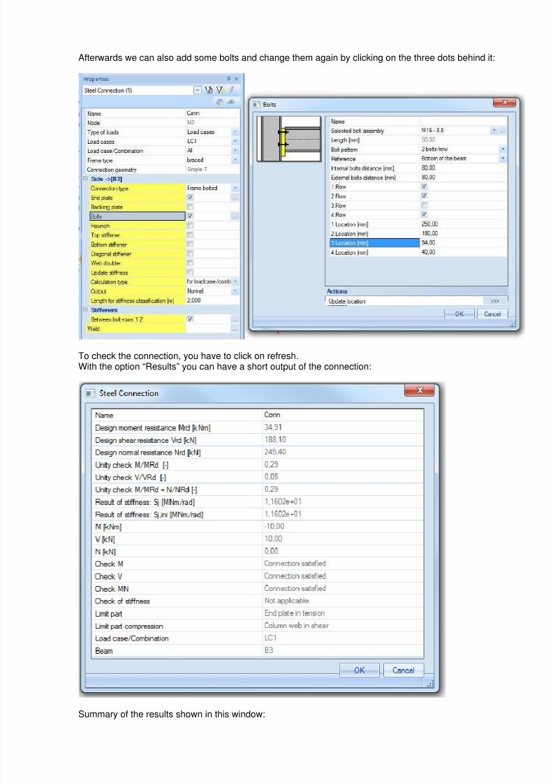
Afterwards we can also add some bolts and change them again by clicking on the three dots behind it:
To check the connection, you have to click on refresh.With the option “Results” you can have a short output of the connection:
Summary of the results shown in this window:
7/23/2019 Calcul Connection in Scia.pdf
http://slidepdf.com/reader/full/calcul-connection-in-sciapdf 9/89
Scia Engineer
Name Name of the connection in Scia Engineer
Design moment resistance Mrd [kNm] Moment resistance of the connection
Design moment resistance Vrd [kN] Shear resistance of the connection
Design moment resistance Nrd [kN] Normal force resistance of the connection
Unity check M/MRd Unity check of the moment
Unity check V/VRd Unity check of the shear force
Unity check M/MRd + N/NRd Unity check of the moment and normal force
Result of stiffness: Sj [MNm/rad] Stiffness of the connection at the moment Med
Result of stiffness: Sj,ini [MNm/rad] Stiffness of the connection for small moments
M [kNm] MEd of the connection
V [kN] VEd of the connection
N [kN] NEd of the connection
Check M Shows if the unity check for the moment check will notexceed 1.00
Check V Shows if the unity check for the shear force check will notexceed 1.00
Check MN Shows if the unity check for the normal force check will notexceed 1.00
Check of stiffness Checks if the stiffness taken into account in the calculationis between the boundaries of the real stiffness of theconnection.
Limit part Shows the limiting part for the tension component
Limit part compression Shows the limiting part for the compression component
Beam The check is done for the beam, shown here.
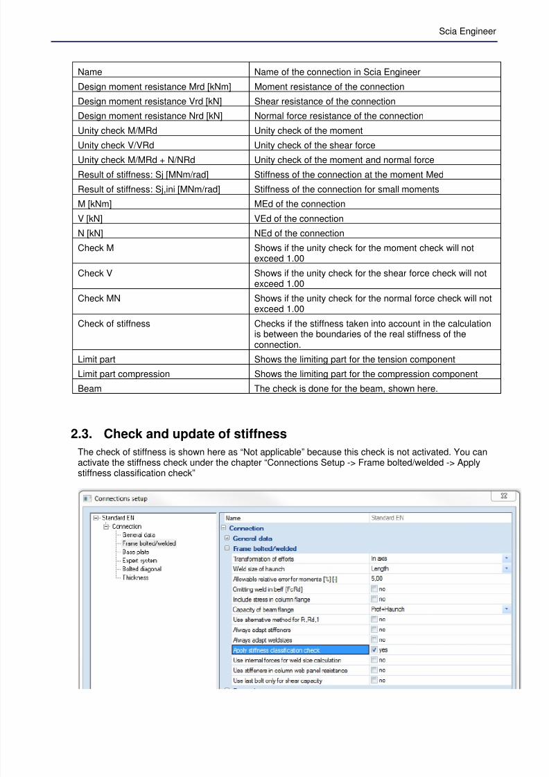
2.3. Check and update of stiffness
The check of stiffness is shown here as “Not applicable” because this check is not activated. You canactivate the stiffness check under the chapter “Connections Setup -> Frame bolted/welded -> Applystiffness classification check”
7/23/2019 Calcul Connection in Scia.pdf
http://slidepdf.com/reader/full/calcul-connection-in-sciapdf 10/89
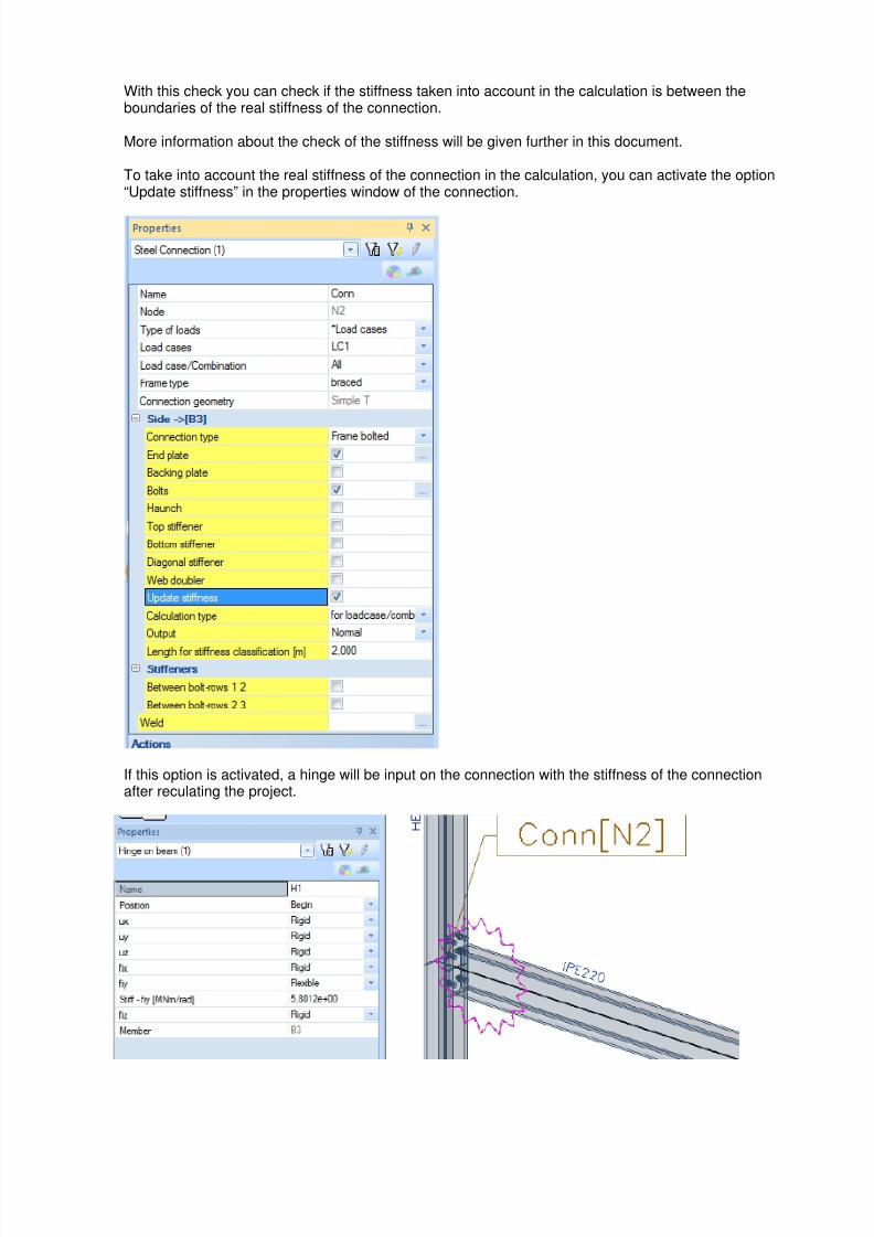
With this check you can check if the stiffness taken into account in the calculation is between theboundaries of the real stiffness of the connection.
More information about the check of the stiffness will be given further in this document.
To take into account the real stiffness of the connection in the calculation, you can activate the option“Update stiffness” in the properties window of the connection.
If this option is activated, a hinge will be input on the connection with the stiffness of the connectionafter reculating the project.
7/23/2019 Calcul Connection in Scia.pdf
http://slidepdf.com/reader/full/calcul-connection-in-sciapdf 11/89
Scia Engineer
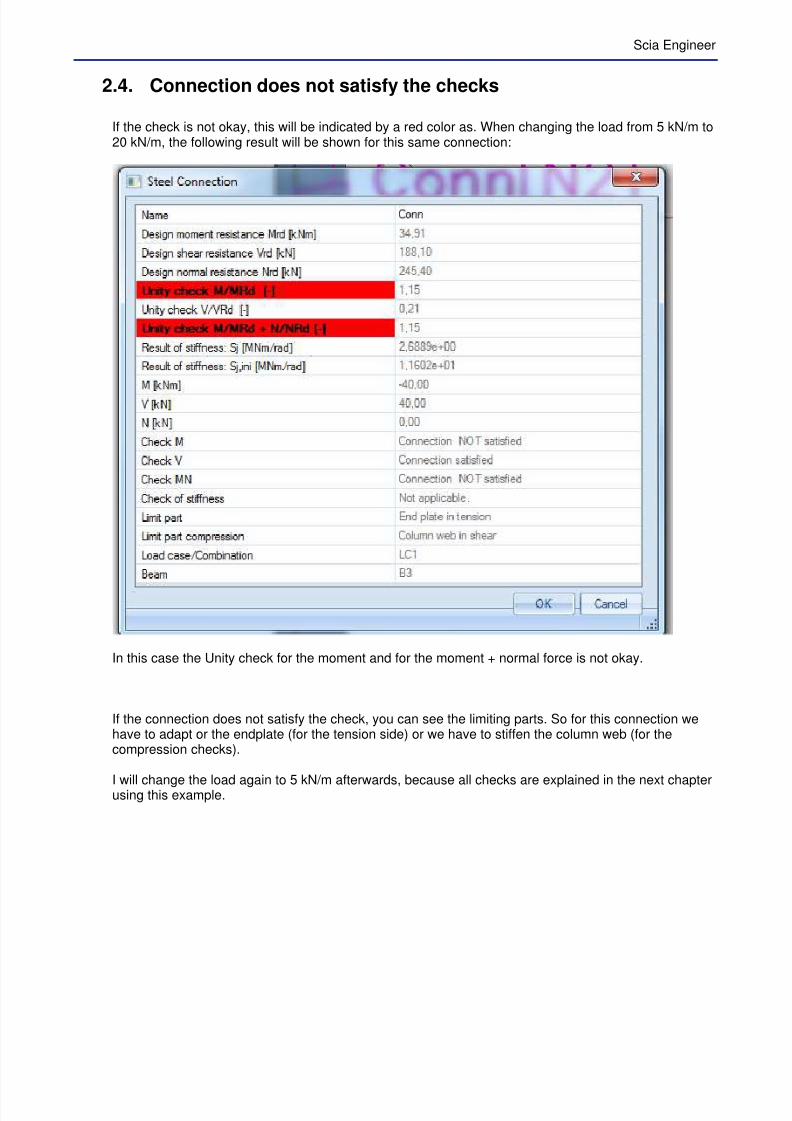
2.4. Connection does not satisfy the checks
If the check is not okay, this will be indicated by a red color as. When changing the load from 5 kN/m to20 kN/m, the following result will be shown for this same connection:
In this case the Unity check for the moment and for the moment + normal force is not okay.
If the connection does not satisfy the check, you can see the limiting parts. So for this connection wehave to adapt or the endplate (for the tension side) or we have to stiffen the column web (for thecompression checks).
I will change the load again to 5 kN/m afterwards, because all checks are explained in the next chapterusing this example.

7/23/2019 Calcul Connection in Scia.pdf
http://slidepdf.com/reader/full/calcul-connection-in-sciapdf 12/89
3. Possible connections in Scia Engineer
The design methods for the column-beam joints are taken from EN 1933-1-8. More detailed informationabout the applied rules and specific implementations are found in Ref.[1].
The following column-beam and beam-beam connections are possible in Scia Engineer:
Only the following cross-sections can be used for connections in Scia Engineer:
Rolled I beam RHS – Rolled hollow section Built up I setion (made of a flatand T section)
Symmetrical welded I section(made of three flats)
Asymmetrical welded I section(made of three flats)
I section with a haunch(elements with variable height)
In the checks in Scia Engineer not only the connection itself will be checked, but also the total joint. A joint is the connection and the web panel in shear, as shown in the picture below.
Joint = web panel in shear + connection
1 - web panel in shear
2 - connection
3 - components (e.g. bolts, endplate)
7/23/2019 Calcul Connection in Scia.pdf
http://slidepdf.com/reader/full/calcul-connection-in-sciapdf 13/89
Scia Engineer
4. Check of the connection (unity check)
The whole check of the chapters below will be discussed using the example made in the chapter“Creation of a small example in Scia Engineer” or using example “CON_004.esa”.
When looking in Scia Engineer at the detailed output you will find the detailed calculation of Scia
Engineer.
In this document we will describe all checks in Scia Engineer step by step based on EN 1993-1-8.Ref.[1].
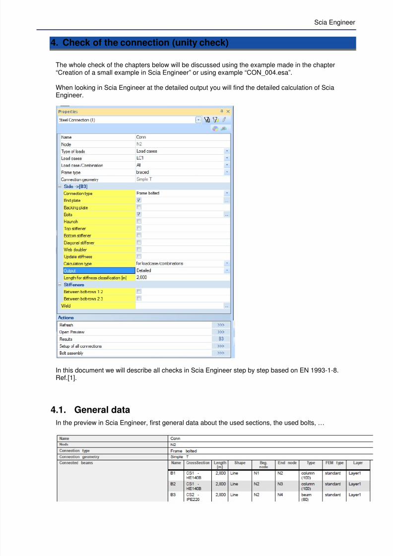
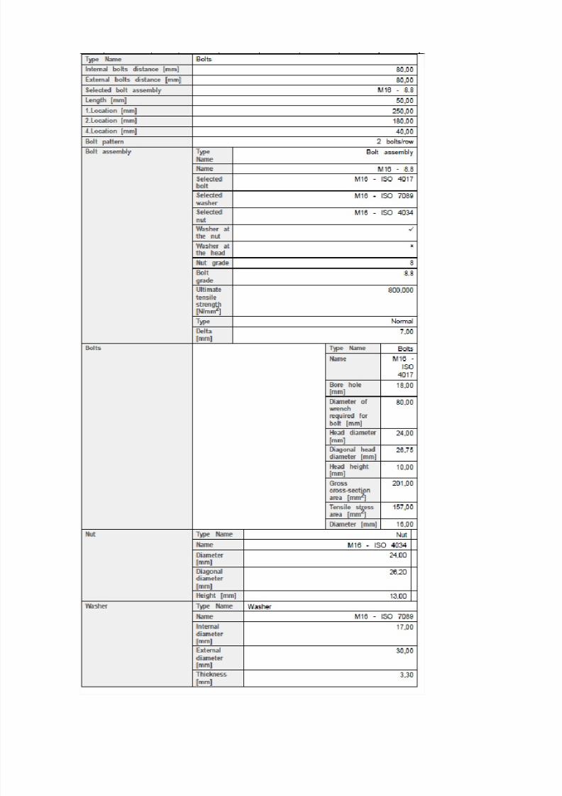
4.1. General data
In the preview in Scia Engineer, first general data about the used sections, the used bolts, …
7/23/2019 Calcul Connection in Scia.pdf
http://slidepdf.com/reader/full/calcul-connection-in-sciapdf 14/89

7/23/2019 Calcul Connection in Scia.pdf
http://slidepdf.com/reader/full/calcul-connection-in-sciapdf 15/89
Scia Engineer
Afterwards the safety factors according EN 1993-1-8 are shown:
Those safety factors can be adapted in the National Annex Setup in Scia Engineer.
And afterwards the internal forces are shown for the chosen load case or combination:
The internal forces, shown here, will result in the biggest unity check or in a stiffness check which is notokay.
You can see in this example that we have a negative moment, so we have tension in the top flange ofthe beam. If we have tension in the bottom flange of the beam, the whole calculation is the same, butthe first bolt-row will be taken as the bottom one.
4.2. Column web panel in shear
As shown in Scia Engineer, this will be calculated following EN 1993-1-8, art. 6.2.6.1:
, = 0,9, √ 3
Shear area of the column:
= − 2 ∙ ∙ + + 2 ∙
= 4300 − 2 ∙ 140 ∙ 12 + + 2 ∙ 1 2 ∙ 12 = 1312 mm²
7/23/2019 Calcul Connection in Scia.pdf
http://slidepdf.com/reader/full/calcul-connection-in-sciapdf 16/89
!"#,$% = 0,9, √ 3
= 0,9 ∙ 23& ∙ 1312√ 3 ∙ 1 ∙ 10'( = )*, ./
In Scia Engineer:
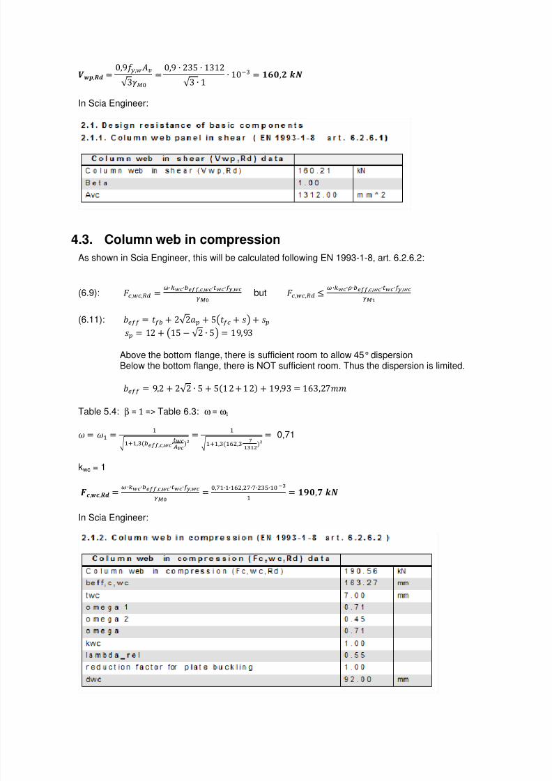
4.3. Column web in compression
As shown in Scia Engineer, this will be calculated following EN 1993-1-8, art. 6.2.6.2:
(6.9): ,, = ∙ ∙5677,,∙8∙,:;< but ,, ∙∙>∙5677,,∙8∙,
:;?
(6.11): @ = 5 + 2√ 2A + &B + CD + C
C = 12 + B1& − √ 2 ∙ &D = 19,93
Above the bottom flange, there is sufficient room to allow 45° dispersionBelow the bottom flange, there is NOT sufficient room. Thus the dispersion is limited.
@ = 9,2 + 2√ 2 ∙ & + &1 2 + 1 2 + 19,93 = 1E3,2FF
Table 5.4: β = 1 => Table 6.3: ω = ω1
G = GH = HI HJH,(5677,,∙KLMN
= HI HJH,(HOP,(∙ Q
?R?SN = 0,71
kwc = 1
TU,"U,$% = ∙∙5677,,∙8∙,:;< = ,VH∙H∙HOP,PV∙V∙P(W∙HXR
H = )Y,Z ./
In Scia Engineer:
7/23/2019 Calcul Connection in Scia.pdf
http://slidepdf.com/reader/full/calcul-connection-in-sciapdf 17/89
Scia Engineer
4.4. Beam flange and web in compression
As shown in Scia Engineer, this will be calculated following EN 1993-1-8, art. 6.2.6.7:
(6.21): TU,[\,$% = ,]^_'87`
= abc∙`:;<∙_'87`
= PdW∙He∙H(W∙HXRH∙PP'f,P = g)Z,Z ./
h, = abc∙`:;< = PdW∙Heiie∙P(W∙HXRjkiiNH = EE9& lmFF = EE,9n lmF
o − 5 = 220 − 9,2 = 210,n0 FF
TU,[\,$% = ,]^_'87`
= OOfVW jiiPH,d ii = g)Z,Z ./
In Scia Engineer:
4.5. Resistance of the T-stub
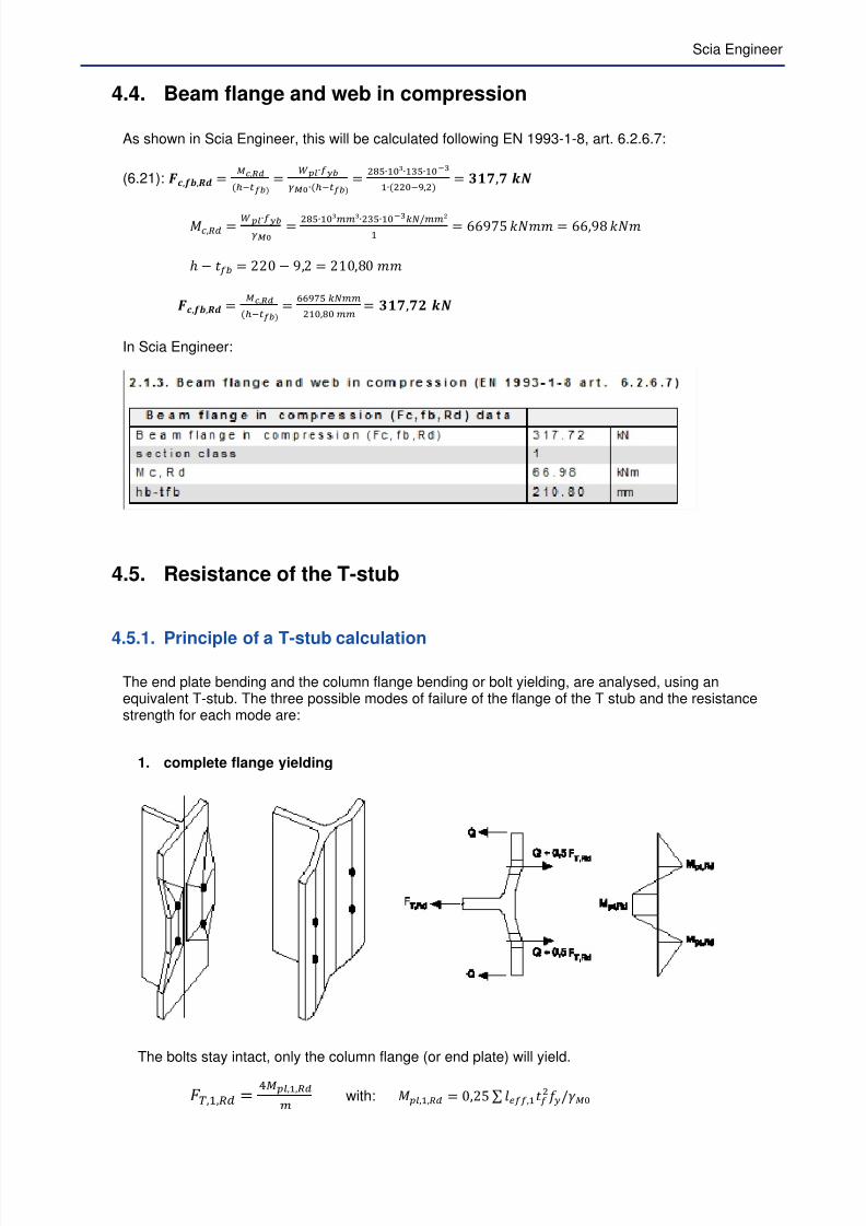
4.5.1. Principle of a T-stub calculation
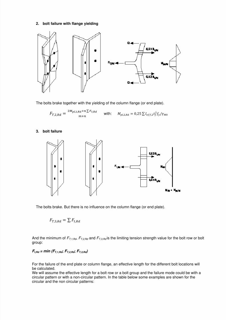
The end plate bending and the column flange bending or bolt yielding, are analysed, using anequivalent T-stub. The three possible modes of failure of the flange of the T stub and the resistancestrength for each mode are:
1. complete flange yielding
The bolts stay intact, only the column flange (or end plate) will yield.
p,H, = qbc,?,]^i with: hr,H, = 0,2& s t@,HP k
7/23/2019 Calcul Connection in Scia.pdf
http://slidepdf.com/reader/full/calcul-connection-in-sciapdf 18/89
2. bolt failure with flange yielding
The bolts brake together with the yielding of the column flange (or end plate).
p,P, = Pbc,S,]^Ju s vK,]^iJu with: hr,P, = 0,2& s t@,PP k
3. bolt failure
The bolts brake. But there is no influence on the column flange (or end plate).
p,(, = s 8,
And the minimum of F T,1,Rd , F T,2,Rd and F T,3,Rd is the limiting tension strength value for the bolt row or boltgroup:
F t,Rd = min (F T,1,Rd ; F T,2,Rd ; F T,3,Rd )
For the failure of the end plate or column flange, an effective length for the different bolt locations willbe calculated.We will assume the effective length for a bolt row or a bolt group and the failure mode could be with acircular pattern or with a non-circular pattern. In the table below some examples are shown for the
circular and the non circular patterns:

7/23/2019 Calcul Connection in Scia.pdf
http://slidepdf.com/reader/full/calcul-connection-in-sciapdf 19/89
Scia Engineer
Circular pattern
Bolt row
Inner bolt row
Non-circular pattern
Bolt row
Inner bolt row
Circular pattern
Bolt group
Inner bolt row
Non-circular pattern
Bolt group
Inner bolt row
End bolt row End bolt row End bolt row End bolt row
Remark: The formulas given for the calculation of FT,Rd for the different failure mode are only applicableif Prying forces may develop. This criterion is given in EN 1993-1-8, Table 6.2:
If no prying forces may develop, Mode 1 and 2 will be calculated as follows:
p,H'P, = 2hr,P,F
7/23/2019 Calcul Connection in Scia.pdf
http://slidepdf.com/reader/full/calcul-connection-in-sciapdf 20/89
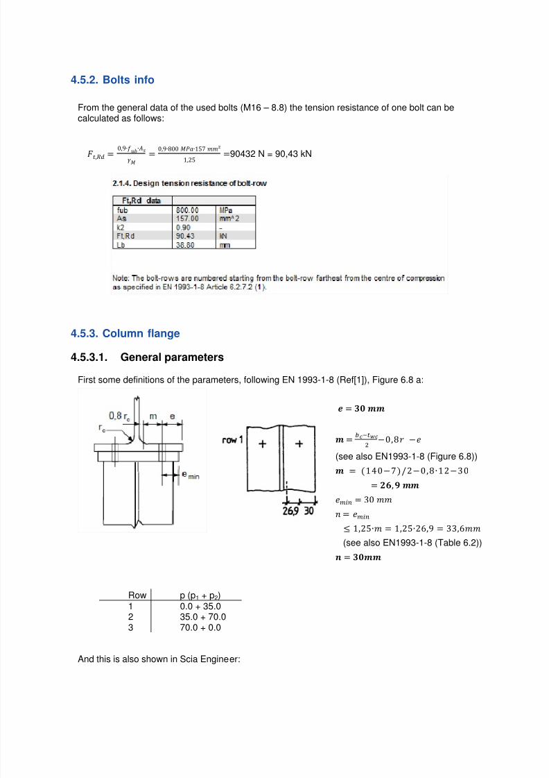
4.5.2. Bolts info
From the general data of the used bolts (M16 – 8.8) the tension resistance of one bolt can becalculated as follows:
,wx = 0,9∙y∙Ch
= 0,9∙n00 hzA∙1& FFN1,2& =90432 N = 90,43 kN
4.5.3. Column flange
4.5.3.1. General parameters
First some definitions of the parameters, following EN 1993-1-8 (Ref[1]), Figure 6.8 a:
{ = g ||
| = 5'8P −0,n −}
(see also EN1993-1-8 (Figure 6.8))
| = 140−k2−0,n∙12−30
= *, Y ||
}i~u = 30 FF
• = }i~u
1,2&∙F = 1,2&∙2E,9 = 33,EFF
(see also EN1993-1-8 (Table 6.2))€ = g||
Row p (p1 + p2)1 0.0 + 35.02 35.0 + 70.03 70.0 + 0.0
And this is also shown in Scia Engineer:

7/23/2019 Calcul Connection in Scia.pdf
http://slidepdf.com/reader/full/calcul-connection-in-sciapdf 21/89
Scia Engineer
To calculate the column flange, we need to choose between the effective lengths of an unstiffenedcolumn flange (Table 6.4 En 1993-1-8 - Ref.[1]) or for the effective lengths of a stiffened column flange(Table 6.5 EN 1993-1-8 - Ref.[1]).
In this case the column flange is unstiffened. In the table below the difference is shown:
Unstiffened column flange Stiffened column flange
So in this example the following table is used for the calculation of the effective lengths:
First we choose for each bolt row the location.In this example:
Row 1 and Row 3: End bolt-rowRow 2: Inner bolt-row
And the same is shown in Scia Engineer:

7/23/2019 Calcul Connection in Scia.pdf
http://slidepdf.com/reader/full/calcul-connection-in-sciapdf 22/89
4.5.3.2. Ft,fc,Rd of bolt rows considered individually
The calculation of leff can be done using Table 6.4. of the EN 1993-1-8 (Ref.[1]).
Row 1leff circular patterns: the smaller of:
2πm = 2*3.14*26,9 = 169,02
πm + e1 = 3.14*26,9 + 1860 = 1944,51
leff non-circular patterns: the smaller of:4m + 1,25e = 4*26,9 + 1,25*30 = 145,10 2m + 0,625e + e1 = 2*26,9 + 0,625*30 + 1860 = 1932,55
Row 2
leff circular patterns: 2πm = 2*3.14*26,9 = 169,02 leff non-circular patterns: 4m + 1,25e = 4*26,9 + 1,25*30 = 145,10
Row 3leff circular patterns: the smaller of:
2πm = 2*3.14*26,9 = 169,02
πm + e1 = 3.14*26,9 + 1930 = 2014,51
leff non-circular patterns: the smaller of:4m + 1,25e = 4*26,9 + 1,25*30 = 145,10 2m + 0,625e + e1 = 2*26,9 + 0,625*30 + 1930 = 2002,55
Row leff circularpatterns
leff non-circularpatterns
1 169,02 145.10
2 169,02 145.10
3 169,02 145.10
In Scia Engineer:
And now from the bottom of Table 6.4:
7/23/2019 Calcul Connection in Scia.pdf
http://slidepdf.com/reader/full/calcul-connection-in-sciapdf 23/89
Scia Engineer
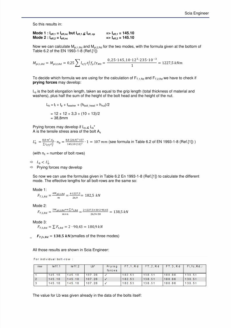
So this results in:
Mode 1 : leff,1 = leff,nc but leff,1 < leff, cp => leff,1 = 145.10Mode 2 : leff,2 = leff,nc => leff,2 = 145.10
Now we can calculate Mpl,1,Rd and Mpl,2,Rd for the two modes, with the formula given at the bottom ofTable 6.2 of the EN 1993-1-8 (Ref.[1])
hr,H, = hr,P, = 0,2& t@P k = 0,2&∙14&,10∙12N∙23&∙10'(1 = 122,& lmF
To decide which formula we are using for the calculation of FT,1,Rd and FT,2,Rd we have to check ifprying forces may develop:
Lb is the bolt elongation length, taken as equal to the grip length (total thickness of material andwashers), plus half the sum of the height of the bolt head and the height of the nut.
Lb = tf + tp + twasher + (hbolt_head + hnut)/2
= 12 + 12 + 3,3 + (10 + 13)/2= 38,8mm
Prying forces may develop if Lb < Lb*A is the tensile stress area of the bolt As
‚5ƒ = d,d ie „…s r67787R
∙ •5 = d,d PO,fe∙HWVHqW,H∙HPe ∙ 1 = 10 FF (see formula in Table 6.2 of EN 1993-1-8 (Ref.[1]) )
(with nb = number of bolt rows)
‚5 † ‚5ƒ
Prying forces may develop So now we can use the formulas given in Table 6.2 En 1993-1-8 (Ref.[1]) to calculate the differentmode. The effective lengths for all bolt-rows are the same so:
Mode 1:
p,H, = qbc,?,]^i = q∙HPPV,W
PO,f = 1n2,& lm
Mode 2:
p,P, = Pbc,S,]^Ju s vK,]^iJu = P∙HPPV,WJ(∙P∙f,q(
PO,fJ( = 13n,& lm
Mode 3:
p,(, = s 8, = 2 ∙ 90,43 = 1n0,9 lm
T‡,[U,$% = )gˆ,‰ ./(smalles of the three modes)
All those results are shown in Scia Engineer:
The value for Lb was given already in the data of the bolts itself:
7/23/2019 Calcul Connection in Scia.pdf
http://slidepdf.com/reader/full/calcul-connection-in-sciapdf 24/89
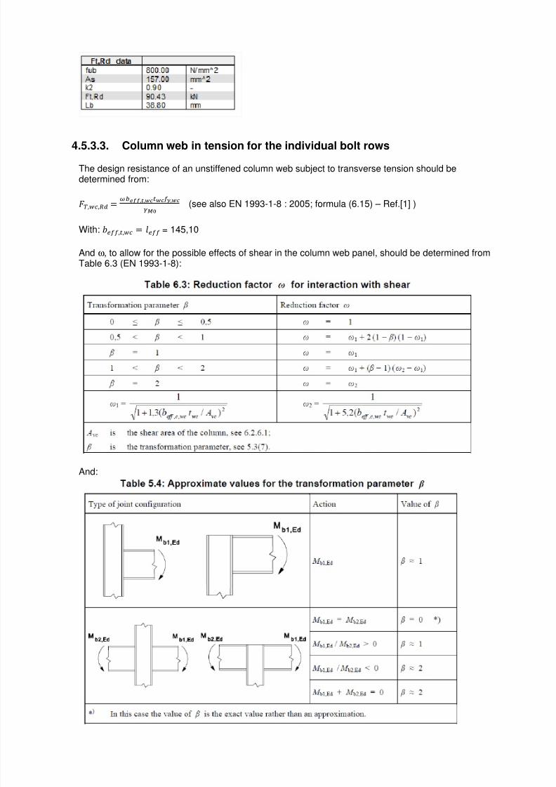
4.5.3.3. Column web in tension for the individual bolt rows
The design resistance of an unstiffened column web subject to transverse tension should bedetermined from:
p,, = 5677,K,8,:;< (see also EN 1993-1-8 : 2005; formula (6.15) – Ref.[1] )
With: @,8, = t@ = 145,10
And ω, to allow for the possible effects of shear in the column web panel, should be determined fromTable 6.3 (EN 1993-1-8):
And:
7/23/2019 Calcul Connection in Scia.pdf
http://slidepdf.com/reader/full/calcul-connection-in-sciapdf 25/89
Scia Engineer
In this example:
β = 1
ω = ω1
G = GH = 1I 1 + 1,3@,, kN
= − 2 ∙ ∙ + Š"U + ‹U ∙
= 4300 − 2 ∙ 140 ∙ 12 + Z + ∙ ) ∙12 = 1312 FFN
G = GH = HI HJH,(5677,,8k„MN
= HŒ HJH,(HqW,H∙VkH(HPN = 0,75
p,, = 5 677,K,8,:;< = ,VW∙HqW,H∙V∙P(W∙HXR
H
T‡,"U,$% = )ZY ./
In Scia Engineer:
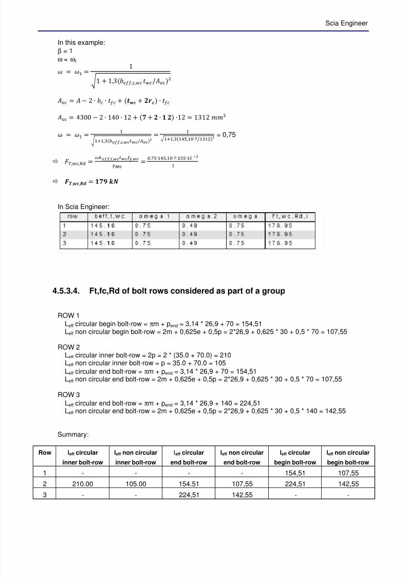
4.5.3.4. Ft,fc,Rd of bolt rows considered as part of a group
ROW 1
Leff circular begin bolt-row = πm + pend = 3,14 * 26,9 + 70 = 154,51Leff non circular begin bolt-row = 2m + 0,625e + 0,5p = 2*26,9 + 0,625 * 30 + 0,5 * 70 = 107,55
ROW 2Leff circular inner bolt-row = 2p = 2 * (35.0 + 70.0) = 210Leff non circular inner bolt-row = p = 35.0 + 70.0 = 105
Leff circular end bolt-row = πm + pend = 3,14 * 26,9 + 70 = 154,51Leff non circular end bolt-row = 2m + 0,625e + 0,5p = 2*26,9 + 0,625 * 30 + 0,5 * 70 = 107,55
ROW 3
Leff circular end bolt-row = πm + pend = 3,14 * 26,9 + 140 = 224,51Leff non circular end bolt-row = 2m + 0,625e + 0,5p = 2*26,9 + 0,625 * 30 + 0,5 * 140 = 142,55
Summary:
Row leff circular
inner bolt-row
leff non circular
inner bolt-row
leff circular
end bolt-row
leff non circular
end bolt-row
leff circular
begin bolt-row
leff non circular
begin bolt-row
1 - - - - 154,51 107,55
2 210.00 105.00 154.51 107,55 224,51 142,55
3 - - 224,51 142,55 - -

7/23/2019 Calcul Connection in Scia.pdf
http://slidepdf.com/reader/full/calcul-connection-in-sciapdf 26/89
In Scia Engineer:
Mode 1 : s t@,H = s t@,u but s t@,H s t@, Mode 2 : s t@,P = s t@,u
Row 1-1 : not considered, same as the individual bolt row.
Row 1-2:s t@, = 1&410+1&4&0 = 30902
s t@,u = 10&& + 10&& = 21&10
Mode 1 = Mode 2 : leff = 215.10
hr,H, = hr,P, = 0,2& t@P k = 0,2&∙21&,1∙12N∙23&∙10'(1 = 1n19,n lmF
Row 1-3:s t@, = 1&4&1+21000 +224&1 = &n902
s t@,u = 10&& + 10&00 + 142&& = 3&&10
Mode 1 = Mode 2 : leff = 355.10
hr,H, = hr,P, = 0,2& s t@P k = ,PW∙(WW,H∙HPN∙P(W∙HXRH = 3004,1 lmF
Prying forces may develop if Lb < Lb*Lb = 38,8mm
Row 1-2:
‚5ƒ = d,d ie „…s r67787R
∙ •5 = d,d PO,fe∙HWVPHW,H∙HPe ∙ 2 = 14& FF
(with nb = number of bolt rows)
‚5 † ‚5ƒ
Prying forces may develop
Row 1-3:
‚5ƒ = d,d ie „…s r67787R
∙ •5 = d,d PO,fe∙HWV(WW,H∙HPe ∙ 3 = 131 FF
(with nb = number of bolt rows)
‚5 † ‚5ƒ
Prying forces may develop
Row 1-2:
Mode 1: p,H, = qbc,?,]^i = q∙HdHf,d
PO,f = 20,E lm
Mode 2: p,P, = Pbc,S,]^Ju s vK,]^iJu = P∙HdHf,dJ(∙q∙f,q(PO,fJ( = 2&4, lm
Mode 3: p,(, = s 8, = 4 ∙ 90,43 = 3E1, lm
T‡,$% = ‰Ž,Z ./

7/23/2019 Calcul Connection in Scia.pdf
http://slidepdf.com/reader/full/calcul-connection-in-sciapdf 27/89
Scia Engineer
Row 1-3:
Mode 1: p,H, = qbc,?,]^i = q∙(q,H
PO,f = 44E, lm
Mode 2: p,P, = Pbc,S,]^Ju s vK,]^iJu = P∙(q,HJ(∙O∙f,q(
PO,fJ( = 391, lm
Mode 3: p,(, = s 8, = E ∙ 90,43 = &42,E lm
T‡,$% = gY),Z ./
In Scia Engineer:
4.5.3.5. Column web in tension for bolt rows considered as part of a group
Row 1-2:
G = GH = HI HJH,(5677,,8k„MN
= HŒ HJH,(PHW,H∙VkH(HPN = 0,61
p,, = 5 677,K,8,:;< = ,OH∙PHW,H∙V∙P(W∙HXR
H
• T‡,"U,$% = )‰ ./
Row 1-3:G = GH = HI HJH,(5677,,8k„MN = HŒ HJH,((WW,H∙VkH(HPN = 0,42
p,, = 5 677,K,8,:;< = ,qP∙(WW,H∙V∙P(W∙HXR
H
T‡,"U,$% = Ž‰ ./
In Scia Engineer:
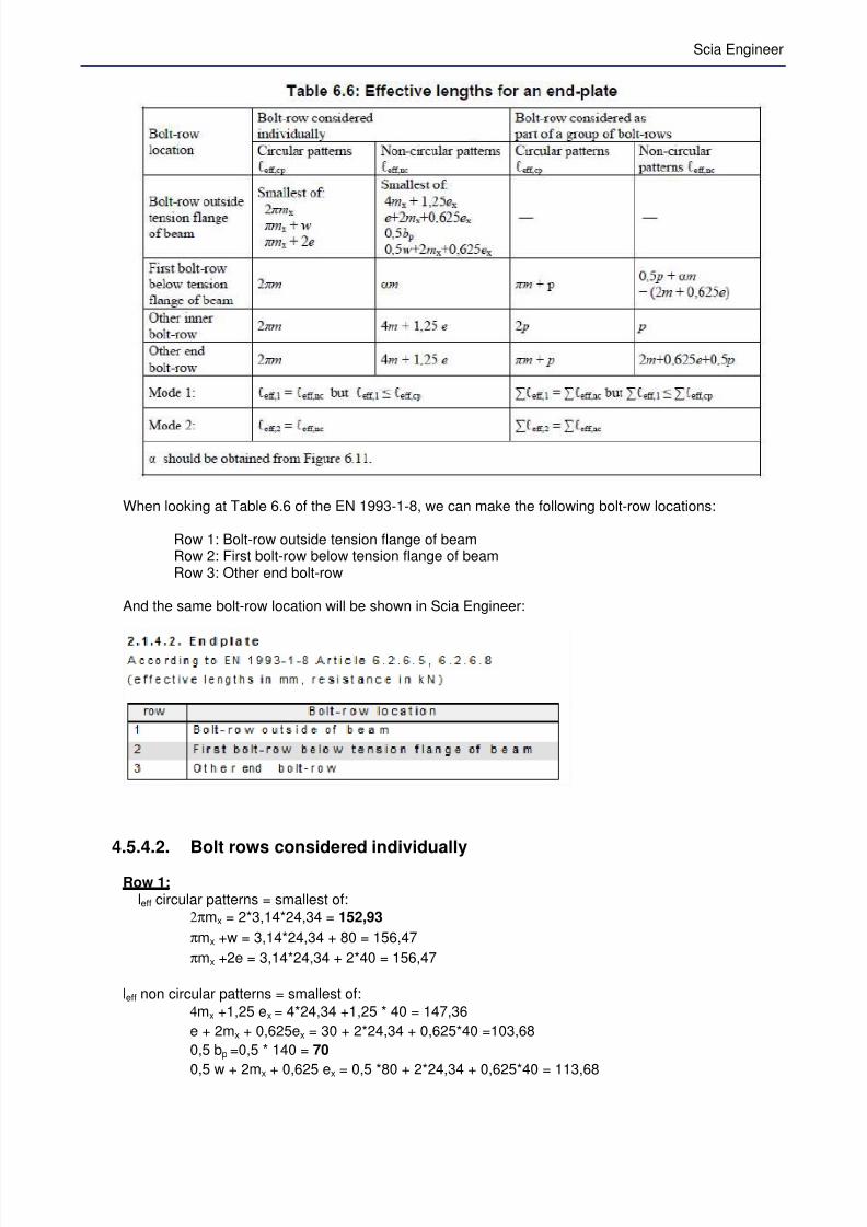
4.5.4. End plate
We can repeat the whole principle of the column flange calculation on the end plate. In this case weare using Table 6.6 of the EN 1993-1-8 (Ref.[1]).
7/23/2019 Calcul Connection in Scia.pdf
http://slidepdf.com/reader/full/calcul-connection-in-sciapdf 28/89
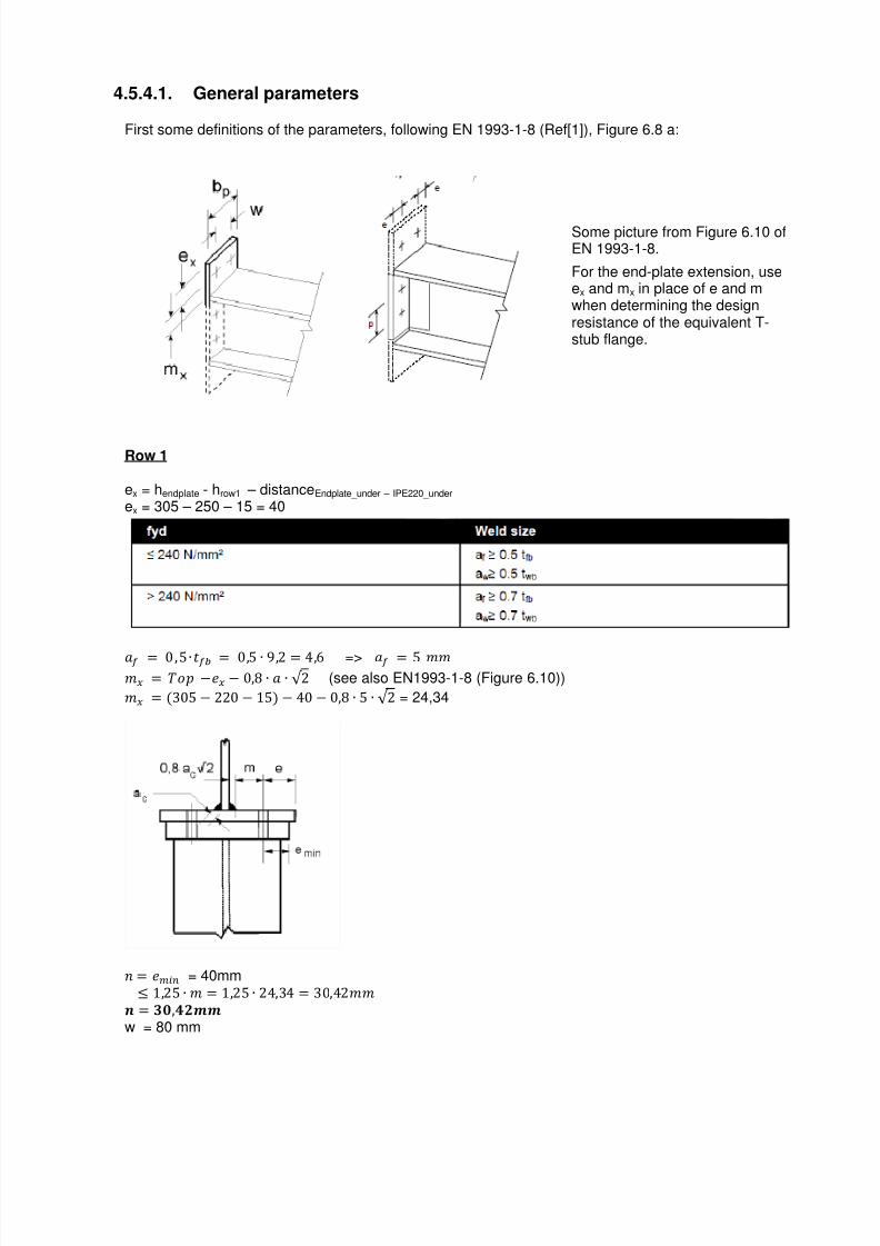
4.5.4.1. General parameters
First some definitions of the parameters, following EN 1993-1-8 (Ref[1]), Figure 6.8 a:
Some picture from Figure 6.10 ofEN 1993-1-8.
For the end-plate extension, useex and mx in place of e and mwhen determining the designresistance of the equivalent T-stub flange.
Row 1
ex = hendplate - hrow1 – distanceEndplate_under – IPE220_under ex = 305 – 250 – 15 = 40
A = 0,&∙5 = 0,& ∙ 9,2 = 4,E => A = & FF F = ‘’ −} − 0,n ∙ A ∙ √ 2 (see also EN1993-1-8 (Figure 6.10))
F = 30& − 220 − 1& − 40 − 0,n ∙ & ∙ √ 2 = 24,34
• = }i~u = 40mm 1,2& ∙ F = 1,2& ∙ 24,34 = 30,42FF
€ = g,Ž|| w = 80 mm
7/23/2019 Calcul Connection in Scia.pdf
http://slidepdf.com/reader/full/calcul-connection-in-sciapdf 29/89
Scia Engineer
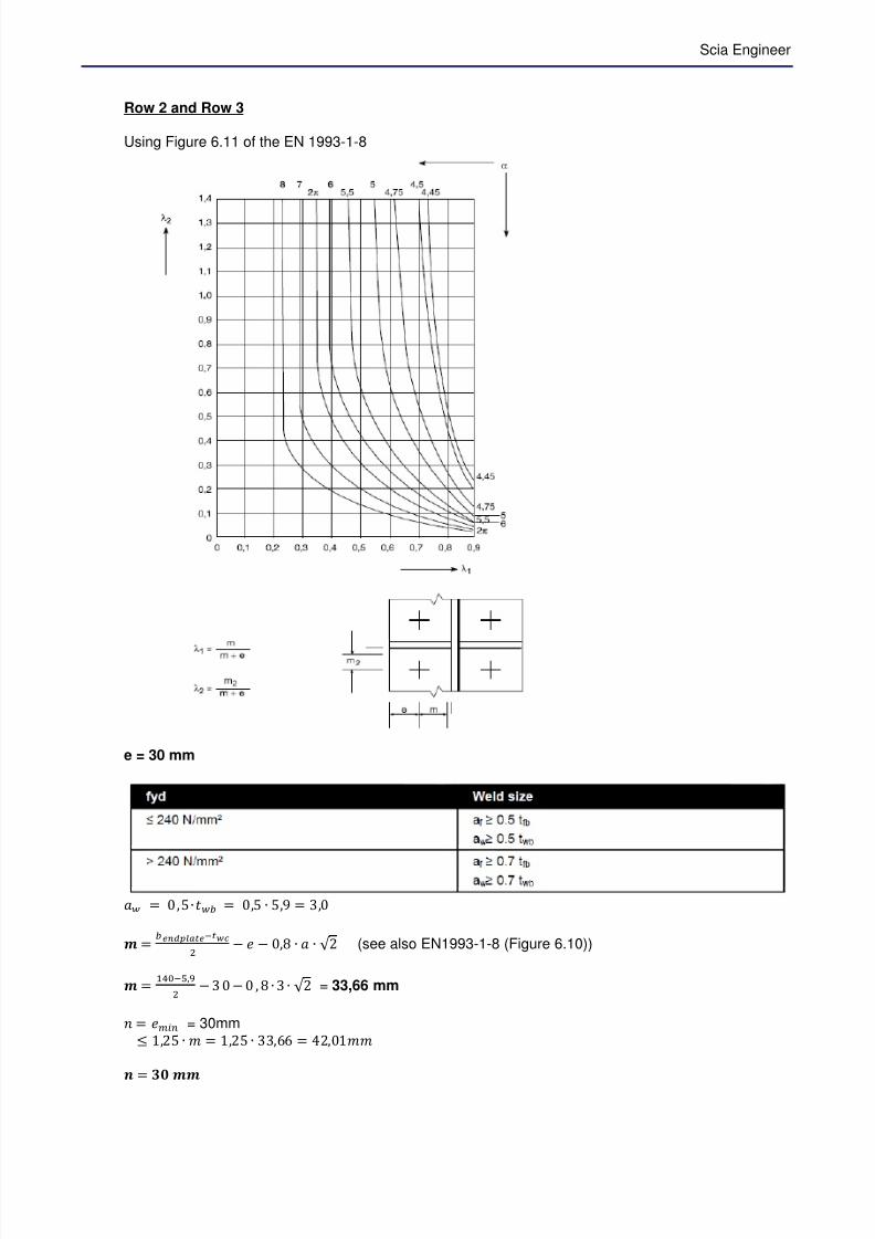
Row 2 and Row 3
Using Figure 6.11 of the EN 1993-1-8
e = 30 mm
A = 0,&∙5 = 0,& ∙ &,9 = 3,0
| = 56“^bc”K6'8P − } − 0,n ∙ A ∙ √ 2 (see also EN1993-1-8 (Figure 6.10))
| = Hq'W,fP − 3 0 − 0 , n ∙ 3 ∙ √ 2 = 33,66 mm
• = }i~u = 30mm 1,2& ∙ F = 1,2& ∙ 33,EE = 42,01FF
€ = g ||

7/23/2019 Calcul Connection in Scia.pdf
http://slidepdf.com/reader/full/calcul-connection-in-sciapdf 30/89
FP,–P = } − − 0,n ∙ A ∙ √ 2
FP,–P = 3& + f,PP − 9,2 − 0 ,n ∙ & ∙ √ 2 = 24,74 mm
FP,–( = o–( − − 0,n ∙ A ∙ √ 2
FP,–( = 3& + f,PP − 9,2 − 0,n ∙ & ∙ √ 2 = 24,74mm
—H = FF + } = 33,EE
33,EE+30 = 0,&3
—P,–P = —P,–( = FP,–PF + } = 24,4
33,EE+30 = 0,39
Alpha = 5,9 (Figure 6.6; EN 1993-1-8)
Row p (p1 + p2) e m n Lambda_1 Lamba_2 alpha
1 0.0 + 35.0 40 (= ex) 24,34 30,42 - - -
2 35.0 + 70.0 30 33,66 30 0,53 0,39 5,99
3 70.0 + 0.0 30 33,66 30 0,53 0,39 5,99
In Scia Engineer:
To calculate the end plate we will use Table 6.6 of the EN 1993-1-8 - Ref.[1].
7/23/2019 Calcul Connection in Scia.pdf
http://slidepdf.com/reader/full/calcul-connection-in-sciapdf 31/89
Scia Engineer
When looking at Table 6.6 of the EN 1993-1-8, we can make the following bolt-row locations:
Row 1: Bolt-row outside tension flange of beamRow 2: First bolt-row below tension flange of beamRow 3: Other end bolt-row
And the same bolt-row location will be shown in Scia Engineer:
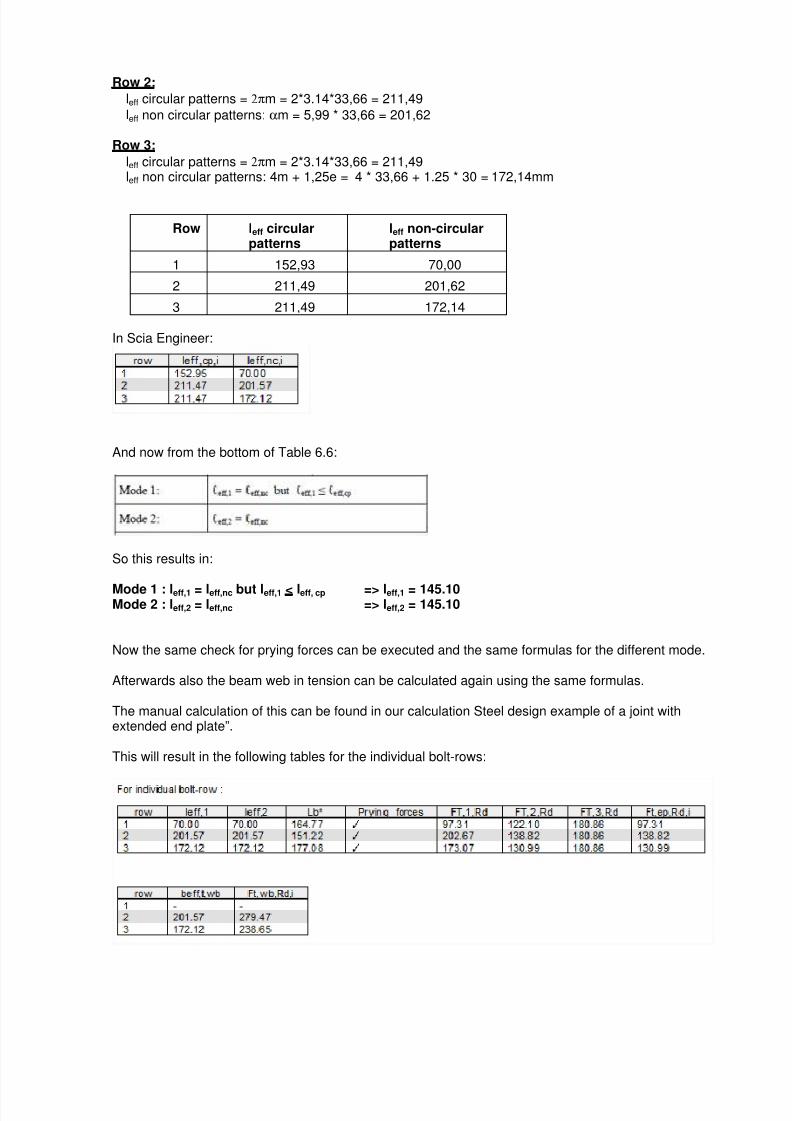
4.5.4.2. Bolt rows considered individually
Row 1:leff circular patterns = smallest of:
2πmx = 2*3,14*24,34 = 152,93
πmx +w = 3,14*24,34 + 80 = 156,47
πmx +2e = 3,14*24,34 + 2*40 = 156,47
leff non circular patterns = smallest of:
4mx +1,25 ex = 4*24,34 +1,25 * 40 = 147,36
e + 2mx + 0,625ex = 30 + 2*24,34 + 0,625*40 =103,68
0,5 bp =0,5 * 140 = 70
0,5 w + 2mx + 0,625 ex = 0,5 *80 + 2*24,34 + 0,625*40 = 113,68
7/23/2019 Calcul Connection in Scia.pdf
http://slidepdf.com/reader/full/calcul-connection-in-sciapdf 32/89
Row 2:
leff circular patterns = 2πm = 2*3.14*33,66 = 211,49
leff non circular patterns: αm = 5,99 * 33,66 = 201,62
Row 3:
leff circular patterns = 2πm = 2*3.14*33,66 = 211,49leff non circular patterns: 4m + 1,25e = 4 * 33,66 + 1.25 * 30 = 172,14mm
Row leff circularpatterns
leff non-circularpatterns
1 152,93 70,00
2 211,49 201,62
3 211,49 172,14
In Scia Engineer:
And now from the bottom of Table 6.6:
So this results in:
Mode 1 : leff,1 = leff,nc but leff,1 < leff, cp => leff,1 = 145.10Mode 2 : leff,2 = leff,nc => leff,2 = 145.10
Now the same check for prying forces can be executed and the same formulas for the different mode.
Afterwards also the beam web in tension can be calculated again using the same formulas.
The manual calculation of this can be found in our calculation Steel design example of a joint withextended end plate”.
This will result in the following tables for the individual bolt-rows:
7/23/2019 Calcul Connection in Scia.pdf
http://slidepdf.com/reader/full/calcul-connection-in-sciapdf 33/89
Scia Engineer
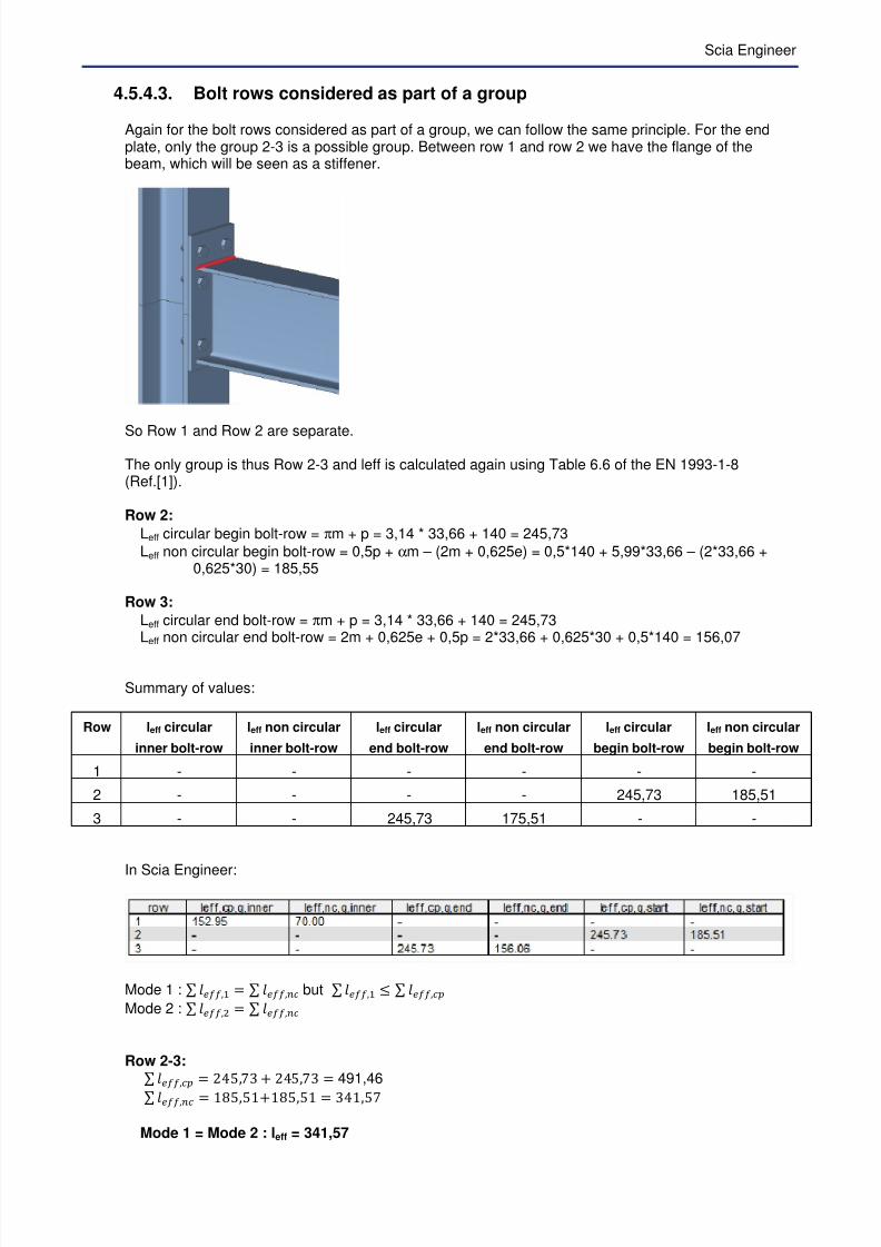
4.5.4.3. Bolt rows considered as part of a group
Again for the bolt rows considered as part of a group, we can follow the same principle. For the endplate, only the group 2-3 is a possible group. Between row 1 and row 2 we have the flange of thebeam, which will be seen as a stiffener.
So Row 1 and Row 2 are separate.
The only group is thus Row 2-3 and leff is calculated again using Table 6.6 of the EN 1993-1-8(Ref.[1]).
Row 2:
Leff circular begin bolt-row = πm + p = 3,14 * 33,66 + 140 = 245,73
Leff non circular begin bolt-row = 0,5p + αm – (2m + 0,625e) = 0,5*140 + 5,99*33,66 – (2*33,66 +0,625*30) = 185,55
Row 3:
Leff circular end bolt-row = πm + p = 3,14 * 33,66 + 140 = 245,73Leff non circular end bolt-row = 2m + 0,625e + 0,5p = 2*33,66 + 0,625*30 + 0,5*140 = 156,07
Summary of values:
Row leff circular
inner bolt-row
leff non circular
inner bolt-row
leff circular
end bolt-row
leff non circular
end bolt-row
leff circular
begin bolt-row
leff non circular
begin bolt-row
1 - - - - - -
2 - - - - 245,73 185,51
3 - - 245,73 175,51 - -
In Scia Engineer:
Mode 1 : s t@,H = s t@,u but s t@,H s t@,
Mode 2 : s t@,P = s t@,u
Row 2-3:
s t@, = 24&,3 + 24&,3 = 491,46
s t@,u = 1n&,&1+1n&,&1 = 341,&
Mode 1 = Mode 2 : leff = 341,57
7/23/2019 Calcul Connection in Scia.pdf
http://slidepdf.com/reader/full/calcul-connection-in-sciapdf 34/89
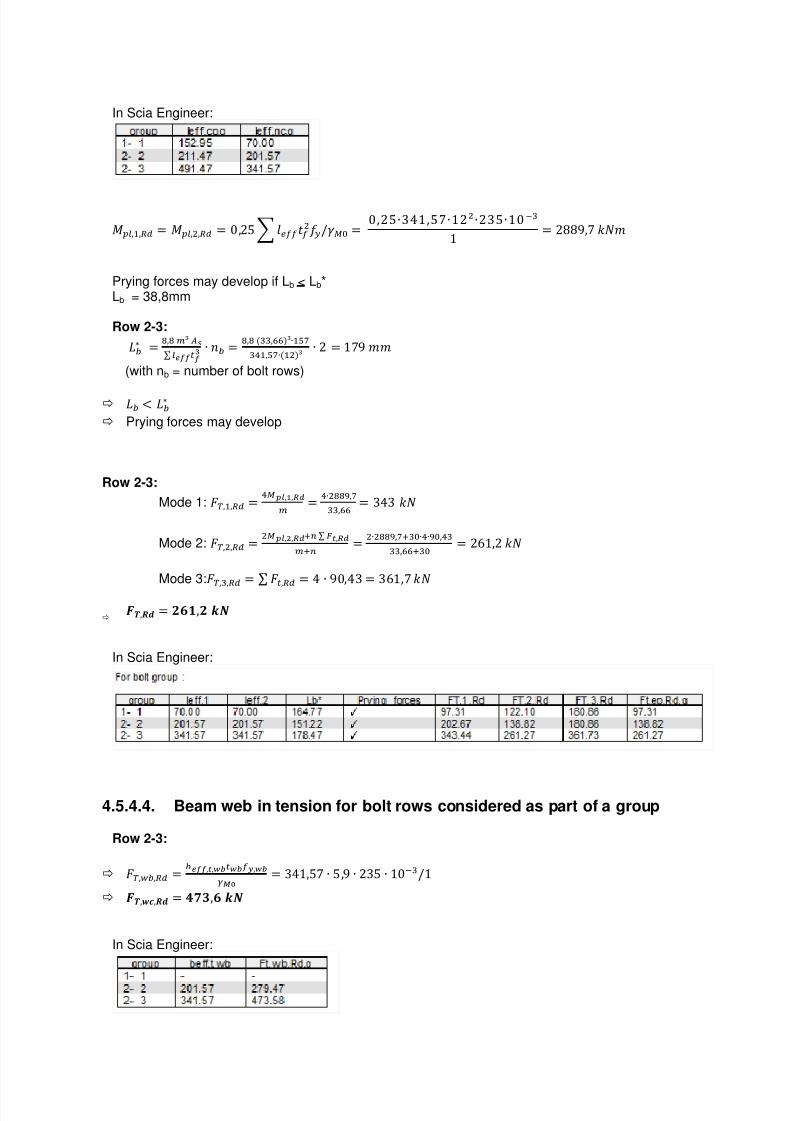
In Scia Engineer:
hr,H, = hr,P, = 0,2& t@P k = 0,2&∙341,&∙12N∙23&∙10'(1 = 2nn9, lmF
Prying forces may develop if Lb < Lb*Lb = 38,8mm
Row 2-3:
‚5ƒ = d,d ie „…s r67787R
∙ •5 = d,d ((,OOe∙HWV(qH,WV∙HPe ∙ 2 = 19 FF
(with nb = number of bolt rows)
‚5 † ‚5ƒ
Prying forces may develop
Row 2-3:
Mode 1: p,H, = qbc,?,]^i = q∙Pddf,V
((,OO = 343 lm
Mode 2: p,P, = Pbc,S,]^Ju s vK,]^iJu = P∙Pddf,VJ(∙q∙f,q(
((,OOJ( = 2E1,2 lm
Mode 3:
p,(, = s 8, = 4 ∙ 90,43 = 3E1, lm
T‡,$% = *), ./
In Scia Engineer:
4.5.4.4. Beam web in tension for bolt rows considered as part of a group
Row 2-3:
p,5, = 5677,K,`8`,`:;< = 341,& ∙ &,9 ∙ 23& ∙ 10'(k1
T‡,"U,$% = ŽZg,* ./
In Scia Engineer:
7/23/2019 Calcul Connection in Scia.pdf
http://slidepdf.com/reader/full/calcul-connection-in-sciapdf 35/89
Scia Engineer
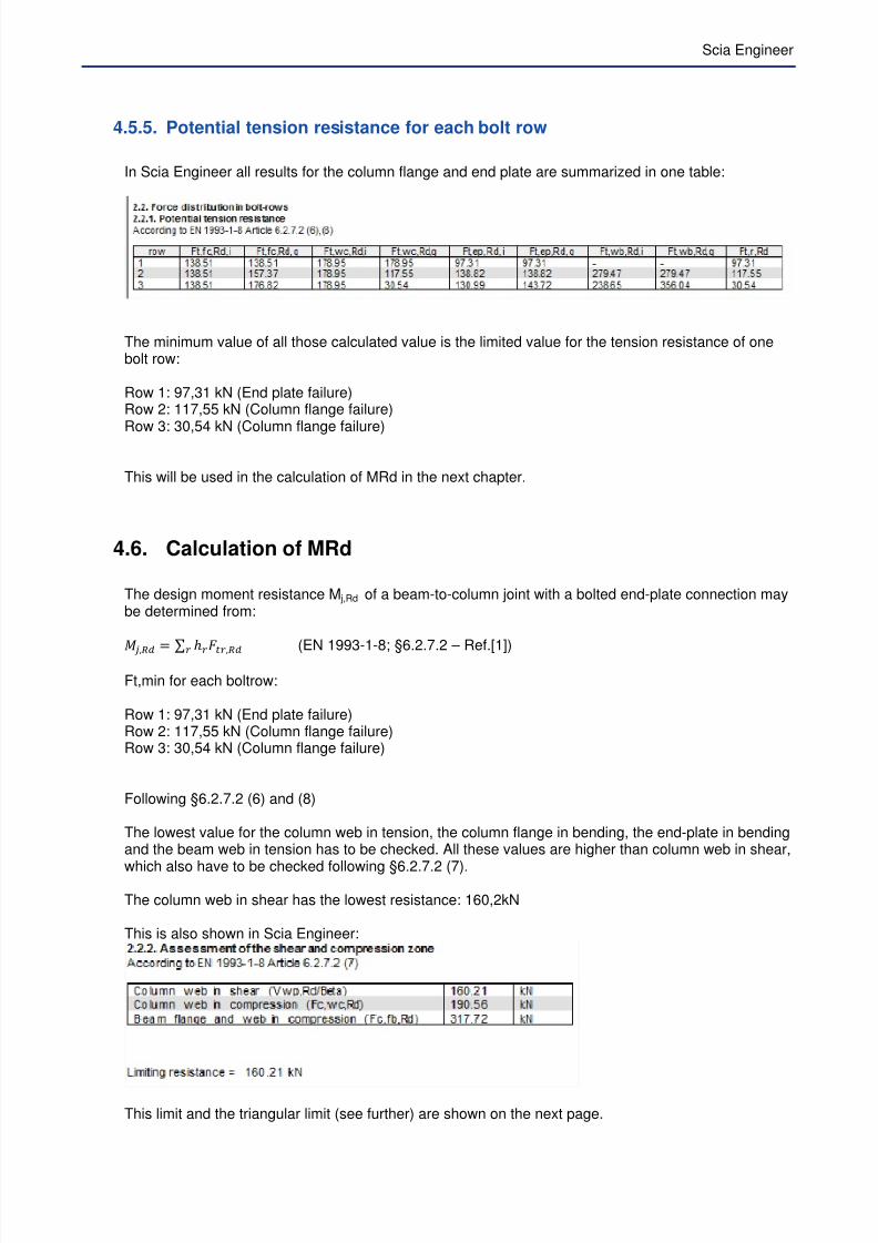
4.5.5. Potential tension resistance for each bolt row
In Scia Engineer all results for the column flange and end plate are summarized in one table:
The minimum value of all those calculated value is the limited value for the tension resistance of onebolt row:
Row 1: 97,31 kN (End plate failure)Row 2: 117,55 kN (Column flange failure)Row 3: 30,54 kN (Column flange failure)
This will be used in the calculation of MRd in the next chapter.
4.6. Calculation of MRd
The design moment resistance M j,Rd of a beam-to-column joint with a bolted end-plate connection maybe determined from:
h̃ , = s o8, (EN 1993-1-8; §6.2.7.2 – Ref.[1])
Ft,min for each boltrow:
Row 1: 97,31 kN (End plate failure)Row 2: 117,55 kN (Column flange failure)Row 3: 30,54 kN (Column flange failure)
Following §6.2.7.2 (6) and (8)
The lowest value for the column web in tension, the column flange in bending, the end-plate in bendingand the beam web in tension has to be checked. All these values are higher than column web in shear,
which also have to be checked following §6.2.7.2 (7).
The column web in shear has the lowest resistance: 160,2kN
This is also shown in Scia Engineer:
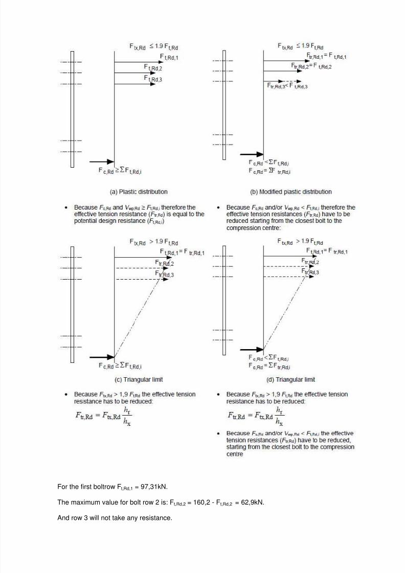
This limit and the triangular limit (see further) are shown on the next page.
7/23/2019 Calcul Connection in Scia.pdf
http://slidepdf.com/reader/full/calcul-connection-in-sciapdf 36/89
For the first boltrow Ft,Rd,1 = 97,31kN.
The maximum value for bolt row 2 is: Ft,Rd,2 = 160,2 - Ft,Rd,2 = 62,9kN.
And row 3 will not take any resistance.
7/23/2019 Calcul Connection in Scia.pdf
http://slidepdf.com/reader/full/calcul-connection-in-sciapdf 37/89
Scia Engineer
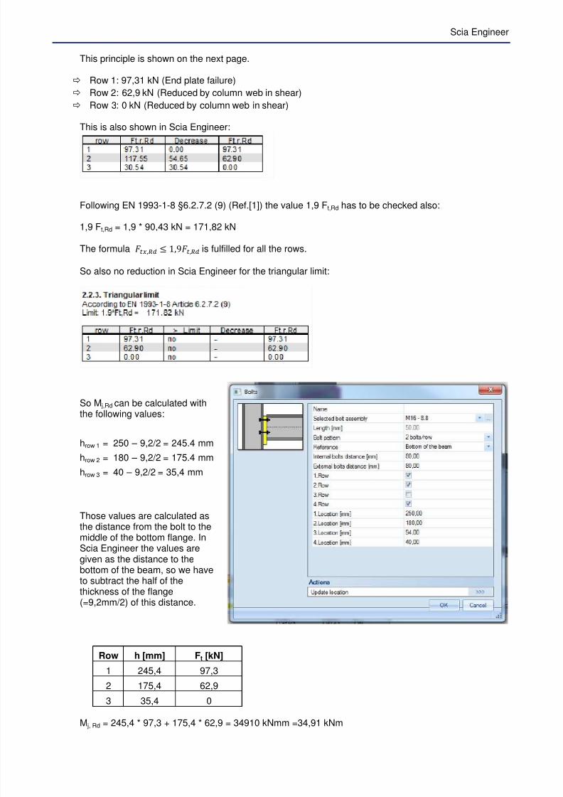
This principle is shown on the next page.
Row 1: 97,31 kN (End plate failure)
Row 2: 62,9 kN (Reduced by column web in shear)
Row 3: 0 kN (Reduced by column web in shear)
This is also shown in Scia Engineer:
Following EN 1993-1-8 §6.2.7.2 (9) (Ref.[1]) the value 1,9 Ft,Rd has to be checked also:
1,9 Ft,Rd = 1,9 * 90,43 kN = 171,82 kN
The formula 8, 1,98, is fulfilled for all the rows.
So also no reduction in Scia Engineer for the triangular limit:
So M j,Rd can be calculated with
the following values:
hrow 1 = 250 – 9,2/2 = 245.4 mm
hrow 2 = 180 – 9,2/2 = 175.4 mm
hrow 3 = 40 – 9,2/2 = 35,4 mm
Those values are calculated asthe distance from the bolt to themiddle of the bottom flange. InScia Engineer the values are
given as the distance to thebottom of the beam, so we haveto subtract the half of thethickness of the flange(=9,2mm/2) of this distance.
Row h [mm] Ft [kN]
1 245,4 97,3
2 175,4 62,9
3 35,4 0
M j, Rd = 245,4 * 97,3 + 175,4 * 62,9 = 34910 kNmm =34,91 kNm

7/23/2019 Calcul Connection in Scia.pdf
http://slidepdf.com/reader/full/calcul-connection-in-sciapdf 38/89
In Scia Engineer:
4.7. Calculation of NRd
The value for N j,Rd is calculated as follows:If N j,Ed is a tensile force, the N j,Rd is determined by critical value for the following components:
- For bolted connection, as a combination for all bolt rows:
- column web in transverse tension- column flange in bending- end plate in bending- beam web in tension- bolts in tension
- For welded connection:
- Column web in transverse tension, where the value for tfb in formulas (6.10) and (6.11) isreplaced by the beam height.
- Column flange in bending, by considering the sum of formula (6.20) at the top and bottomflange of the beam.
- If N j,Ed is a compressive force, the N j,Rd is determined by the following components:o Column web in transverse compression, where the value for tfb in formulas (6.16) is
replaced by the beam height.o Column flange in bending, by considering the sum of formula (6.20) at the top and
bottom flange of the beam.
In all cases, N j,Rd≤ Npl,Rd.
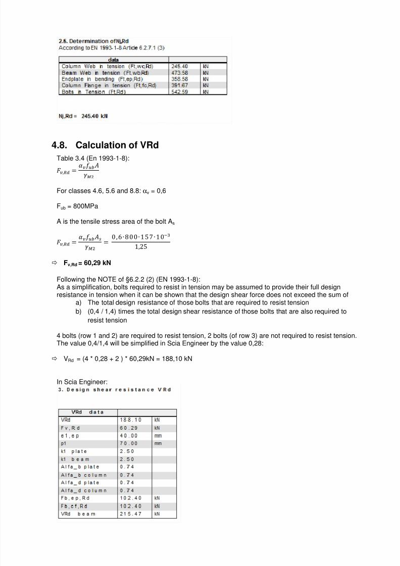
In our example the normal force resistance NRd will be calculated as the minimum of the following 5values:
Column web in tension:
This is calculated for the bolt group 1-3 for the column flange:
245, 40 kN

7/23/2019 Calcul Connection in Scia.pdf
http://slidepdf.com/reader/full/calcul-connection-in-sciapdf 39/89
Scia Engineer
Beam Web in tension:
This is calculated for the bolt group 2-3 for the endplate:
473,58 kN
Endplate in bending:
Here the most limiting value of the endplate (individual rows and groups) will be calculated.
In this case the limiting value is
o Bolt row 1
o Group of bolt row 2+3
And this results in: 97,31 kN + 261,27 kN = 358,58 kN
Column Flange in tension:
This is calculated for the bolt group 1-3 for the Column flange:
391,68 kN
Bolts in Tension:
6 bolts and FT,Rd for one bolt = 90,43 kN 6 x 90,43 kN = 542,58 kN
Nj,Rd
Minimum of all previous values
245,40 kN
In Scia Engineer:
7/23/2019 Calcul Connection in Scia.pdf
http://slidepdf.com/reader/full/calcul-connection-in-sciapdf 40/89
4.8. Calculation of VRd
Table 3.4 (En 1993-1-8):
, = ™ š5 P
For classes 4.6, 5.6 and 8.8: αv = 0,6
Fub = 800MPa
A is the tensile stress area of the bolt As
, = ™ š5 ›P
= 0, E ∙ n00∙ 1&∙ 10'(1,2&
Fv,Rd = 60,29 kN
Following the NOTE of §6.2.2 (2) (EN 1993-1-8):As a simplification, bolts required to resist in tension may be assumed to provide their full design
resistance in tension when it can be shown that the design shear force does not exceed the sum ofa) The total design resistance of those bolts that are required to resist tension
b) (0,4 / 1,4) times the total design shear resistance of those bolts that are also required to
resist tension
4 bolts (row 1 and 2) are required to resist tension, 2 bolts (of row 3) are not required to resist tension.The value 0,4/1,4 will be simplified in Scia Engineer by the value 0,28:
VRd = (4 * 0,28 + 2 ) * 60,29kN = 188,10 kN
In Scia Engineer:
7/23/2019 Calcul Connection in Scia.pdf
http://slidepdf.com/reader/full/calcul-connection-in-sciapdf 41/89
Scia Engineer
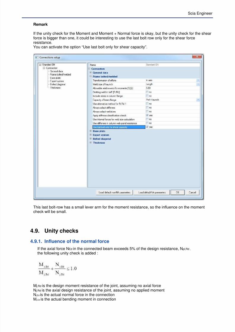
Remark
If the unity check for the Moment and Moment + Normal force is okay, but the unity check for the shearforce is bigger than one, it could be interesting to use the last bolt row only for the shear forceresistance.You can activate the option “Use last bolt only for shear capacity”.
This last bolt-row has a small lever arm for the moment resistance, so the influence on the momentcheck will be small.
4.9. Unity checks4.9.1. Influence of the normal force
If the axial force NEd in the connected beam exceeds 5% of the design resistance, Npl,Rd ,
the following unity check is added :
M j.Rd is the design moment resistance of the joint, assuming no axial force
N j.Rd is the axial design resistance of the joint, assuming no applied momentN j,Ed is the actual normal force in the connectionM j,Ed is the actual bending moment in connection

7/23/2019 Calcul Connection in Scia.pdf
http://slidepdf.com/reader/full/calcul-connection-in-sciapdf 42/89
4.9.2. General unity checks
Assume following internal forces in this connection:
NSd = 0 kNVSd = 10 kN
My,Sd = 10 kNm
Check M: M/MRd = 10/34,9 = 0,29 < 1 => ok!
Check V: V/VRd = 10/189,48 = 0,05 < 1 => ok!
Check MN: M/MRd + N/NRd = 10/34,9 + 0 = 0,29 < 1 => ok!
In Scia Engineer:
7/23/2019 Calcul Connection in Scia.pdf
http://slidepdf.com/reader/full/calcul-connection-in-sciapdf 43/89
Scia Engineer
5. Stiffness of the connection
5.1. The Moment-Rotation characteristic
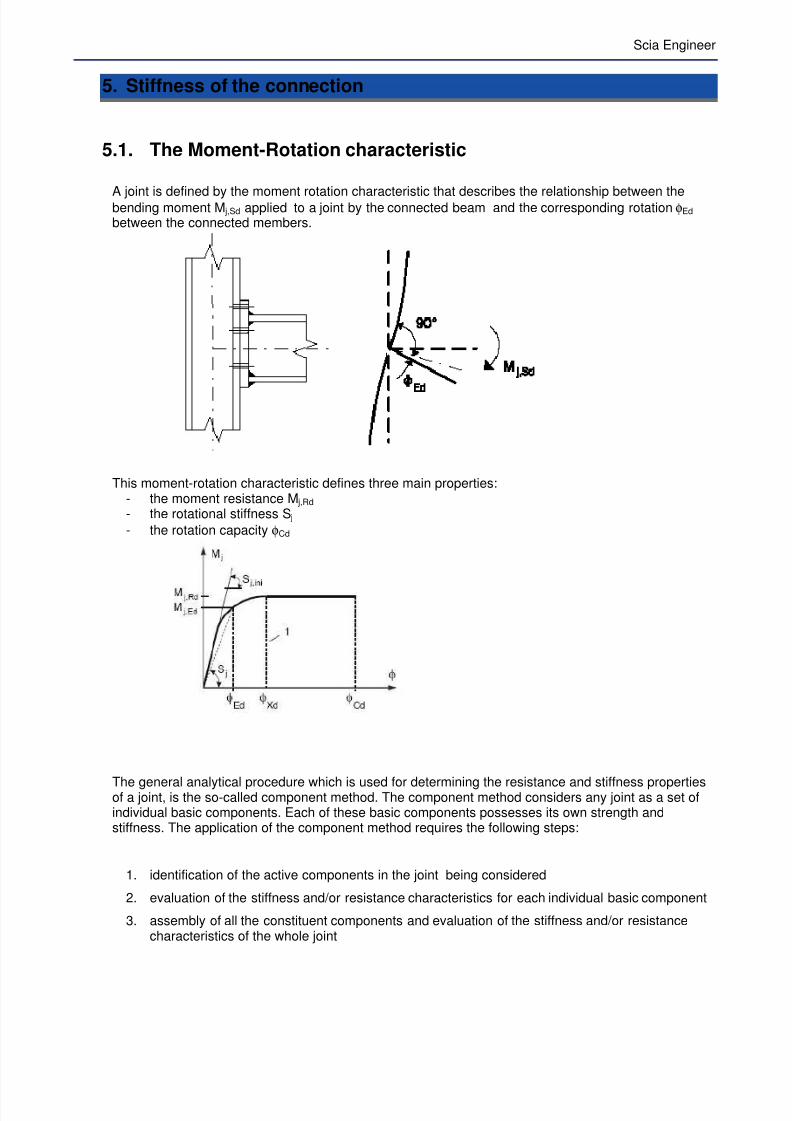
A joint is defined by the moment rotation characteristic that describes the relationship between thebending moment M j,Sd applied to a joint by the connected beam and the corresponding rotation φEd between the connected members.
This moment-rotation characteristic defines three main properties:- the moment resistance M j,Rd - the rotational stiffness S j
- the rotation capacity φCd
The general analytical procedure which is used for determining the resistance and stiffness propertiesof a joint, is the so-called component method. The component method considers any joint as a set ofindividual basic components. Each of these basic components possesses its own strength andstiffness. The application of the component method requires the following steps:
1. identification of the active components in the joint being considered
2. evaluation of the stiffness and/or resistance characteristics for each individual basic component
3. assembly of all the constituent components and evaluation of the stiffness and/or resistancecharacteristics of the whole joint
7/23/2019 Calcul Connection in Scia.pdf
http://slidepdf.com/reader/full/calcul-connection-in-sciapdf 44/89
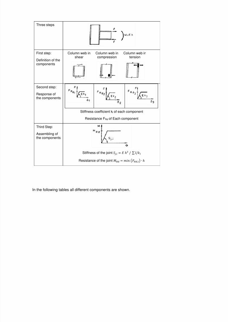
Three steps
First step:
Definition of thecomponents
Column web in
shear
Column web in
compression
Column web in
tension
Second step:
Response ofthe components
Stiffness coefficient ki of each component
Resistance FRd of Each component
Third Step:
Assembling ofthe components
Stiffness of the joint œ̃ ,~ = oN k s tkl~
Resistance of the joint h = Fž• B,~D ∙ o
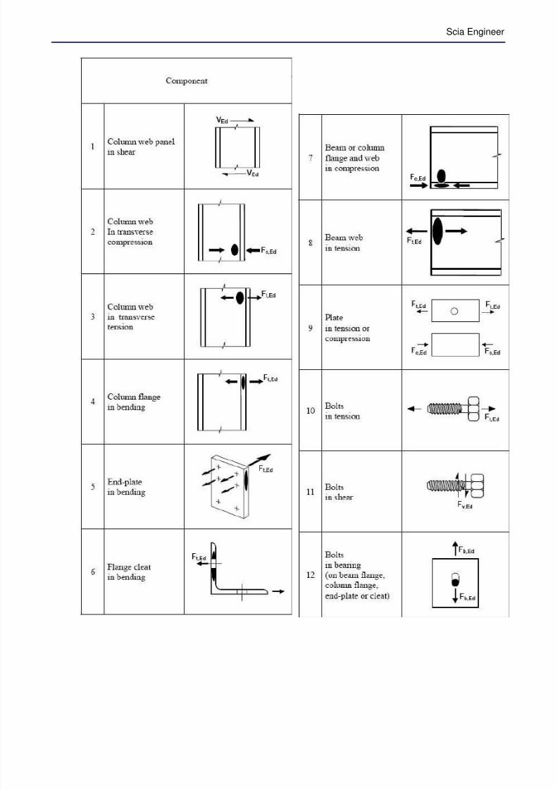
In the following tables all different components are shown.
7/23/2019 Calcul Connection in Scia.pdf
http://slidepdf.com/reader/full/calcul-connection-in-sciapdf 45/89
Scia Engineer
7/23/2019 Calcul Connection in Scia.pdf
http://slidepdf.com/reader/full/calcul-connection-in-sciapdf 46/89
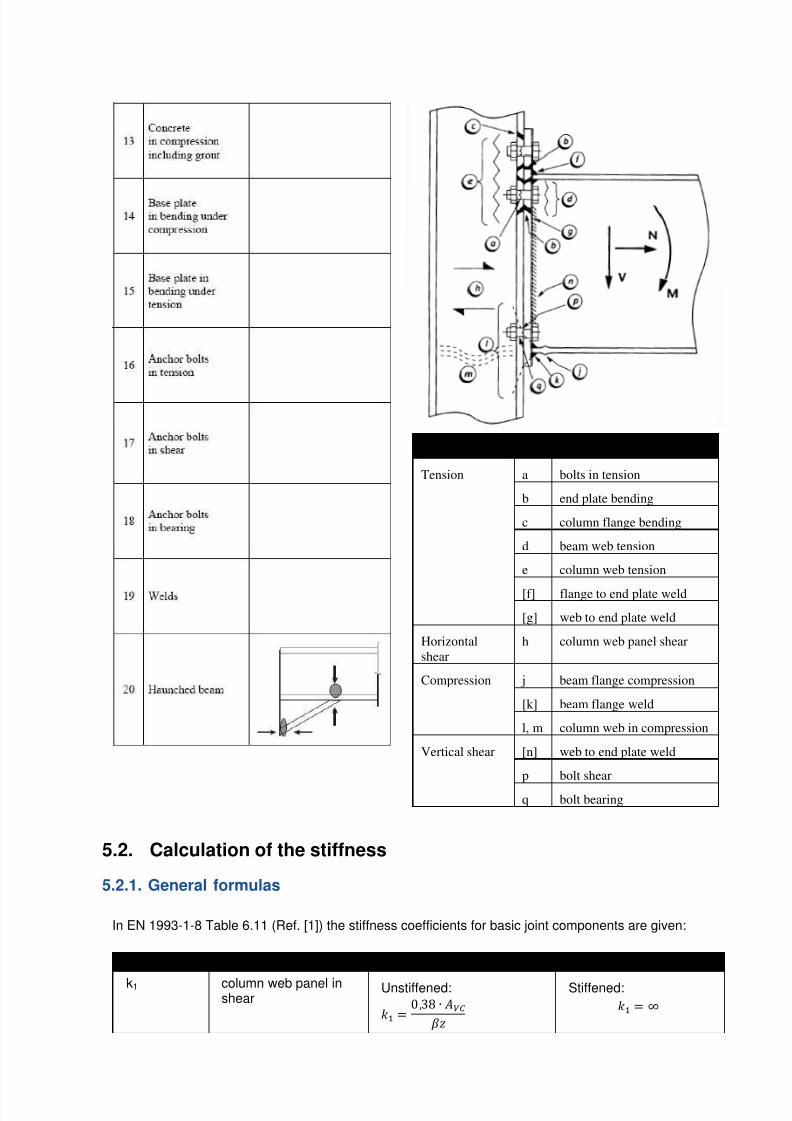
Zone Ref
Tension a bolts in tension
b end plate bending
c column flange bending
d beam web tension
e column web tension
[f] flange to end plate weld
[g] web to end plate weld
Horizontal
shear
h column web panel shear
Compression j beam flange compression
[k] beam flange weld
l, m column web in compression
Vertical shear [n] web to end plate weld
p bolt shear
q bolt bearing
5.2. Calculation of the stiffness
5.2.1. General formulas
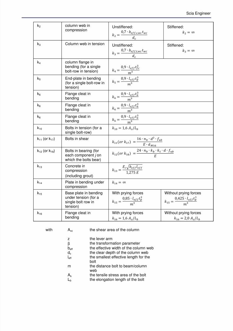
In EN 1993-1-8 Table 6.11 (Ref. [1]) the stiffness coefficients for basic joint components are given:
Coefficient Basic component Formula
k1 column web panel inshear
Unstiffened:
lH = 0,3n ∙ Ÿ¡¢
Stiffened:
lH = £
7/23/2019 Calcul Connection in Scia.pdf
http://slidepdf.com/reader/full/calcul-connection-in-sciapdf 47/89
Scia Engineer
k2 column web incompression
Unstiffened:
lP = 0, ∙ @,, x
Stiffened:
lP = £
k3 Column web in tension Unstiffened:
l( = 0, ∙ @,8,
x
Stiffened:
l( = £
k4 column flange inbending (for a singlebolt-row in tension) lq =
0,9 ∙ t@
Fe
k5 End-plate in bending(for a single bolt-row intension)
lW = 0,9 ∙ t@
Fe
k6 Flange cleat inbending lO =
0,9 ∙ t@¤
Fe
k6 Flange cleat inbending lO =
0,9 ∙ t@¤
Fe
k6 Flange cleat inbending lO = 0,9 ∙ t@¤
Fe
k10 Bolts in tension (for asingle bolt-row)
lH = 1,E ›k‚5
k11 (or k17) Bolts in shearlHH(‘ lHV) =
1E ∙ •5 ∙ xN ∙ š5
∙ xHO
k12 (or k18) Bolts in bearing (foreach component j onwhich the bolts bear)
lHP(‘ lHd) = 24 ∙ •5 ∙ l5 ∙ l8 ∙ x ∙ š5
k13 Concrete incompression
(including grout)
lH = Π@t@
1,2&
k14 Plate in bending undercompression
lHq = £
k15 Base plate in bendingunder tension (for asingle bolt row intension)
With prying forces
lHW = 0,n& ∙ t@
Fe
Without prying forces
lHW = 0,42& ∙ t@
Fe
k16 Flange cleat inbending
With prying forces
lHO = 1,E ›k‚5
Without prying forces
lHO = 2,0 ›k‚5
with Avc
the shear area of the column
z the lever arm
β the transformation parameter
beff the effective width of the column webdc the clear depth of the column webleff the smallest effective length for the
boltm the distance bolt to beam/column
webAs the tensile stress area of the boltLb the elongation length of the bolt

7/23/2019 Calcul Connection in Scia.pdf
http://slidepdf.com/reader/full/calcul-connection-in-sciapdf 48/89
5.2.2. Calculation of the stiffness in detail
In Table 6.10 of the EN 1993-1-8 (Ref.[1]) the stiffness coefficients which has to be taken into account,are given.
For this connection (Single – sided), k1, k2, k3, k4 and k10 has to be calculated, using the formulas of
Table 6.11 of EN 1993-1-8.
5.2.2.1. Column web in tension: k3
l( = 0, @,8, x
beff,t,wc is the effective width of the column web in tension from 6.2.6.3. For a joint with a single bolt-
row in tension, beff,t,wc should be taken as equal to the smallest of the effective lengths leff given for
this bolt-row in Table 6.4 or Table 6.5.
@,8,,–H = 10,&&
@,8,,–P = 10&
.g,‹¥") = ,Z ∙ )Z,‰‰ ∙ ZY = 5,73 mm
.g,‹¥" = ,Z ∙ )‰ ∙ ZY = 5,59 mm
In Scia Engineer:
7/23/2019 Calcul Connection in Scia.pdf
http://slidepdf.com/reader/full/calcul-connection-in-sciapdf 49/89
Scia Engineer
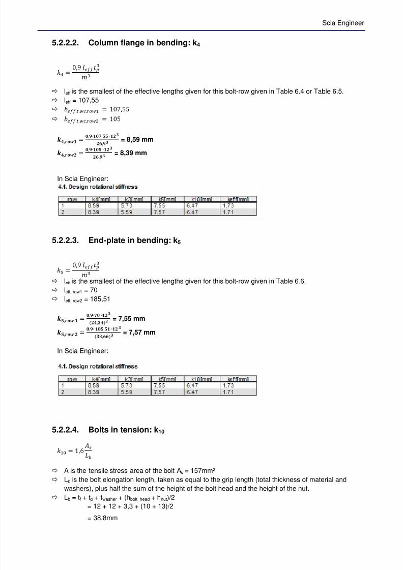
5.2.2.2. Column flange in bending: k4
lq = 0,9 t@(F(
leff is the smallest of the effective lengths given for this bolt-row given in Table 6.4 or Table 6.5.
leff = 107,55 @,8,,–H = 10,&&
@,8,,–P = 10&
.Ž,‹¥") = ,Y∙)Z,‰‰ ∙)g*,Yg = 8,59 mm
.Ž,‹¥" = ,Y∙)‰ ∙)g*,Yg = 8,39 mm
In Scia Engineer:
5.2.2.3. End-plate in bending: k5
lW = 0,9 t@(F(
leff is the smallest of the effective lengths given for this bolt-row given in Table 6.6.
leff, row1 = 70
leff, row2 = 185,51
.‰,‹¥" ) = ,Y∙Z ∙)gŽ,gŽg = 7,55 mm
.‰,‹¥" = ,Y∙ )ˆ‰,‰) ∙)ggg,**g = 7,57 mm
In Scia Engineer:
5.2.2.4. Bolts in tension: k10
lH = 1,E ›‚5
A is the tensile stress area of the bolt As = 157mm²
Lb is the bolt elongation length, taken as equal to the grip length (total thickness of material and
washers), plus half the sum of the height of the bolt head and the height of the nut.
Lb = tf + tp + twasher + (hbolt_head + hnut)/2
= 12 + 12 + 3,3 + (10 + 13)/2
= 38,8mm

7/23/2019 Calcul Connection in Scia.pdf
http://slidepdf.com/reader/full/calcul-connection-in-sciapdf 50/89
.) = ), * ∙ )‰Zgˆ,ˆ = *,ŽZ mm
In Scia Engineer:
5.2.2.5. Equivalent stiffness
The effective stiffness keff,r for bolt-row r should be determined from
l@, = 1k s H¦,§
~ (see also formula (6.30) of EN 1993-1-8 – Ref.[1])
In the case of a beam-to-column joint with an end-plate connection, keq should be based upon (and
replace) the stiffness coefficients ki fork3, k4, k5 and k10.
- l¨©©,ª«¬H = H?
-,QRJ ?®,-¯J ?
Q,--J ?°,±Q
= 1,3
- l¨©©,ª«¬P = H?
-,-¯J ?®,R¯J ?
Q,-QJ ?°,±Q
= 1,1
In Scia Engineer:
The equivalent lever arm zeq should be determined from:
¢@² = s l@,oPs l@,o
= l@,–Ho–HP + l@,–Po–PPl@,–Ho–H + l@,–Po–P
= 1,3 ∙ 24&,4N + 1,1 ∙ 1&,4N1,3∙24&,4+1,1∙1&,4
¢@² = 1&E9124,4n = 21E,42 FF
The equivalent stiffness keq can now be determined from:
l@² = s 677,§_§§³6´ (see also formula (6.29) from En 1993-1-8 (Ref.[1]))
l@² = 1,3 ∙ 24&,4 + 1,1 ∙ 1&,421E,42 = 3,3& FF
And those values are also given in Scia Engineer:
7/23/2019 Calcul Connection in Scia.pdf
http://slidepdf.com/reader/full/calcul-connection-in-sciapdf 51/89
Scia Engineer
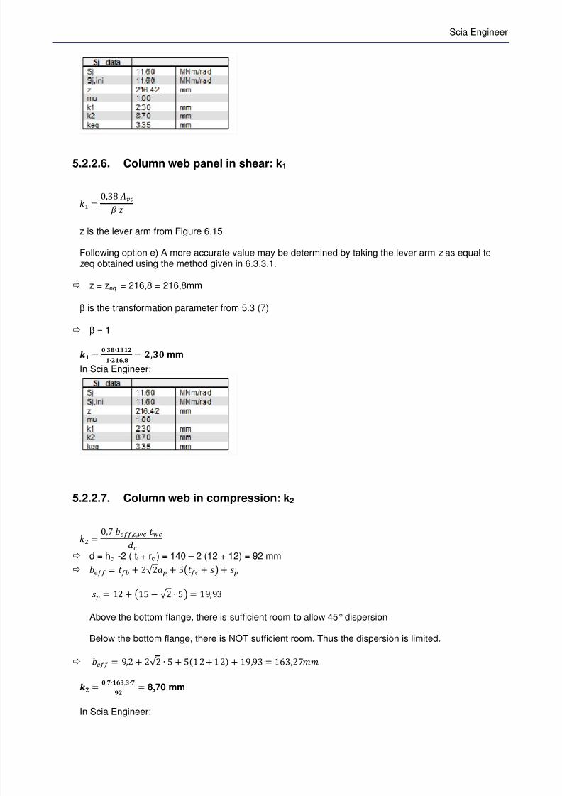
5.2.2.6. Column web panel in shear: k1
lH = 0,3n ¡ ¢
z is the lever arm from Figure 6.15
Following option e) A more accurate value may be determined by taking the lever arm z as equal toz eq obtained using the method given in 6.3.3.1.
z = zeq = 216,8 = 216,8mm
β is the transformation parameter from 5.3 (7)
β = 1
.) = ,gˆ∙)g))∙)*,ˆ = ,g mm
In Scia Engineer:
5.2.2.7. Column web in compression: k2
lP = 0, @,, x
d = hc -2 ( tf + rc ) = 140 – 2 (12 + 12) = 92 mm @ = 5 + 2√ 2A + &B + CD + C
C = 12 + B1& − √ 2 ∙ &D = 19,93
Above the bottom flange, there is sufficient room to allow 45° dispersion
Below the bottom flange, there is NOT sufficient room. Thus the dispersion is limited.
@ = 9,2 + 2√ 2 ∙ & + &1 2 + 1 2 + 19,93 = 1E3,2FF
.
= ,Z∙)*g,g∙Z
Y = 8,70 mm
In Scia Engineer:

7/23/2019 Calcul Connection in Scia.pdf
http://slidepdf.com/reader/full/calcul-connection-in-sciapdf 52/89
5.2.2.8. Design rotational stiffness
When all different stiffness of all components are known, we can assembly this to one stiffness for the joint.
The program will calculate 3 stiffnesses :
Sj,ini the initial rotational stiffnessSj the rotational stiffness, related to the actual moment M j,Sd Sj,MRd the rotational stiffness, related to Mj,Rd
(without the influence of the normal force)
The moment-rotation diagram is based on the values of Sj,ini and Sj,MRd.

7/23/2019 Calcul Connection in Scia.pdf
http://slidepdf.com/reader/full/calcul-connection-in-sciapdf 53/89
Scia Engineer
Sj,MRd
Sj,ini
M
fi
MRd
0.66 MRd
œ̃ = µ ³N¶ s ?
·¦¦ = µ ³N
¶ ∙¸ ?·?J ?
·SJ ?·6´¹
z = 216,4 mm
µ is the stiffness ration S j, ini / S j
o If M j,Ed < M j,Rd => µ = 1
o If 2/3 M j,Rd < M j,Ed < M j,Rd => µ = (1,5 M j,Ed / M j, Rd)ψ
M j,Ed = 10 kNm
M j,Rd = 34,9 kNm => 2/3 M j,Rd = 23,3 kNm
µ = 1
œ̃ = µ ³N¶ s ?
·¦¦
œ̃ = PH ∙PHO,qPNH ∙ ?
S,R<J ?®,Q<J ?
R,R- ∙ 10'O = 11596 kNm/rad
In Scia Engineer:
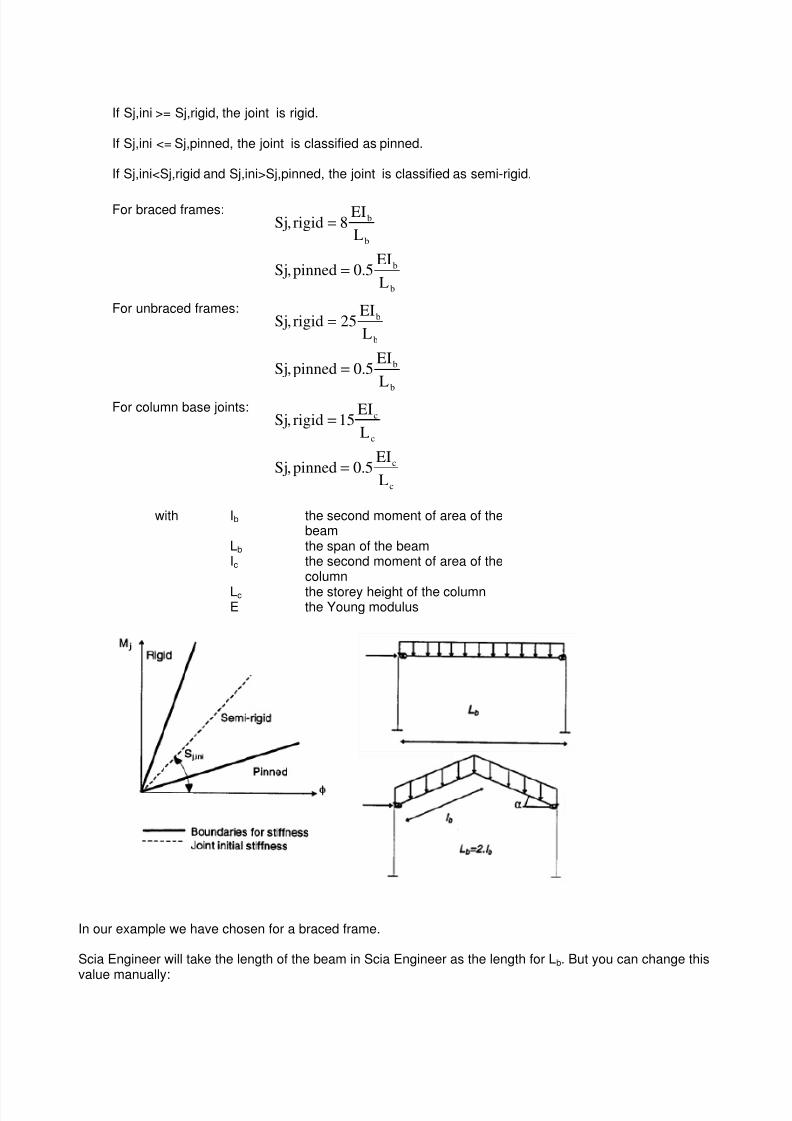
5.3. The classification on stiffnessThe joint is classified as rigid, pinned or semi-rigid according to its stiffness by using the initial rotationalstiffness Sj,ini and comparing this with classification boundaries given in EN 1993-1-8 (Ref. [1]).
7/23/2019 Calcul Connection in Scia.pdf
http://slidepdf.com/reader/full/calcul-connection-in-sciapdf 54/89
If Sj,ini >= Sj,rigid, the joint is rigid.
If Sj,ini <= Sj,pinned, the joint is classified as pinned.
If Sj,ini<Sj,rigid and Sj,ini>Sj,pinned, the joint is classified as semi-rigid.
For braced frames:
b
b
b
b
L
EI5.0pinned,Sj
L
EI8rigid,Sj
=
=
For unbraced frames:
b
b
b
b
L
EI5.0pinned,Sj
L
EI25rigid,Sj
=
=
For column base joints:
c
c
c
c
L
EI5.0pinned,Sj
L
EI15rigid,Sj
=
=
with Ib the second moment of area of thebeam
Lb the span of the beamIc the second moment of area of the
column
Lc the storey height of the columnE the Young modulus
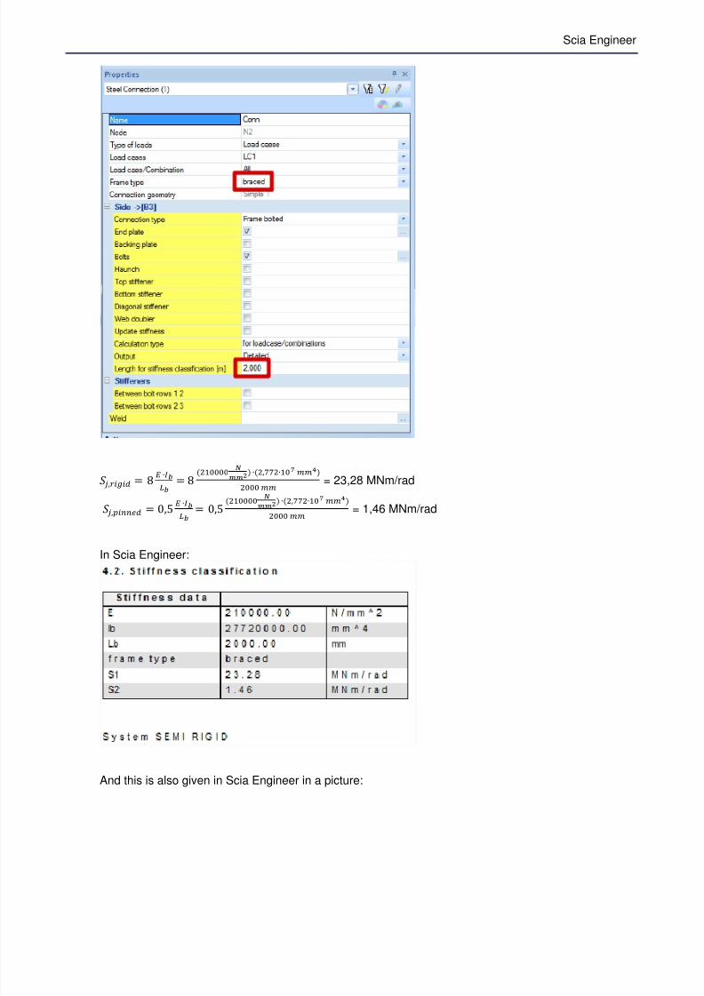
In our example we have chosen for a braced frame.
Scia Engineer will take the length of the beam in Scia Engineer as the length for Lb. But you can change thisvalue manually:
7/23/2019 Calcul Connection in Scia.pdf
http://slidepdf.com/reader/full/calcul-connection-in-sciapdf 55/89
Scia Engineer
œ̃ ,~º~ = n µ ∙»`¼` = n PH ½
¾¾S ∙P,VVP∙HQ ii±P ii = 23,28 MNm/rad
œ̃ ,~uu@ = 0,& µ ∙»`
¼`
= 0,& PH ½¾¾S ∙P,VVP∙HQ ii±
P ii = 1,46 MNm/rad
In Scia Engineer:
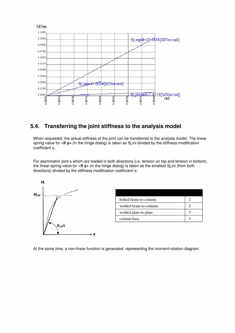
And this is also given in Scia Engineer in a picture:
7/23/2019 Calcul Connection in Scia.pdf
http://slidepdf.com/reader/full/calcul-connection-in-sciapdf 56/89
5.4. Transferring the joint stiffness to the analysis model
When requested, the actual stiffness of the joint can be transferred to the analysis model. The linearspring value for <fi y> (in the hinge dialog) is taken as Sj,ini divided by the stiffness modification
coefficient η.
For asymmetric joint s which are loaded in both directions (i.e. tension on top and tension in bottom),the linear spring value for <fi y> (in the hinge dialog) is taken as the smallest Sj,ini (from both
directions) divided by the stiffness modification coefficient η:
Type of joint η
bolted beam-to-column 2
welded beam-to-column 2
welded plate-to-plate 3
column base 3
At the same time, a non-linear function is generated, representing the moment-rotation diagram.
7/23/2019 Calcul Connection in Scia.pdf
http://slidepdf.com/reader/full/calcul-connection-in-sciapdf 57/89
Scia Engineer
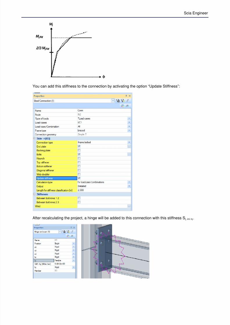
You can add this stiffness to the connection by activating the option “Update Stiffness”:
After recalculating the project, a hinge will be added to this connection with this stiffness S j, ini / η.
7/23/2019 Calcul Connection in Scia.pdf
http://slidepdf.com/reader/full/calcul-connection-in-sciapdf 58/89
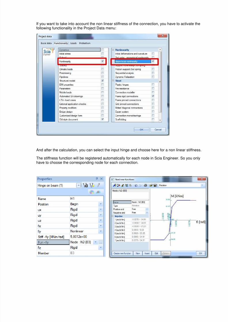
If you want to take into account the non linear stiffness of the connection, you have to activate thefollowing functionality in the Project Data menu:
And after the calculation, you can select the input hinge and choose here for a non linear stiffness.
The stiffness function will be registered automatically for each node in Scia Engineer. So you onlyhave to choose the corresponding node for each connection.
7/23/2019 Calcul Connection in Scia.pdf
http://slidepdf.com/reader/full/calcul-connection-in-sciapdf 59/89
Scia Engineer
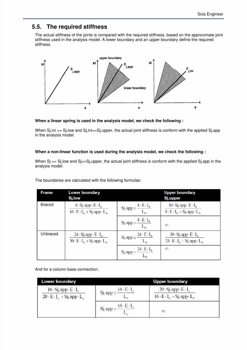
5.5. The required stiffness
The actual stiffness of the joints is compared with the required stiffness, based on the approximate jointstiffness used in the analysis model. A lower boundary and an upper boundary define the requiredstiffness.
When a linear spring is used in the analysis model, we check the following :
When Sj,ini >= Sj,low and Sj,ini<=Sj,upper, the actual joint stiffness is conform with the applied Sj,appin the analysis model.
When a non-linear function is used during the analysis model, we check the following :
When Sj >= Sj,low and Sj<=Sj,upper, the actual joint stiffness is conform with the applied Sj,app in theanalysis model.
The boundaries are calculated with the following formulas:
And for a column base connection:
7/23/2019 Calcul Connection in Scia.pdf
http://slidepdf.com/reader/full/calcul-connection-in-sciapdf 60/89
with Ib the second moment of area of the beam
Lb the span of the beamIc the second moment of area of the columnLc the storey height of the columnE the Young modulusSj,app the approximate joint stiffnessSj,ini the actual initial joint stiffnessSj,low the lower boundary stiffnessSj,upper the upper boundary stiffnessSj the actual joint stiffness
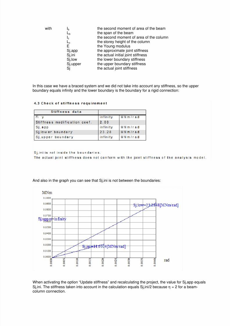
In this case we have a braced system and we did not take into account any stiffness, so the upperboundary equals infinity and the lower boundary is the boundary for a rigid connection:
And also in the graph you can see that Sj,ini is not between the boundaries:
When activating the option “Update stiffness” and recalculating the project, the value for Sj,app equals
Sj,ini. The stiffness taken into account in the calculation equals Sj,ini/2 because η = 2 for a beam-column connection.
7/23/2019 Calcul Connection in Scia.pdf
http://slidepdf.com/reader/full/calcul-connection-in-sciapdf 61/89
Scia Engineer
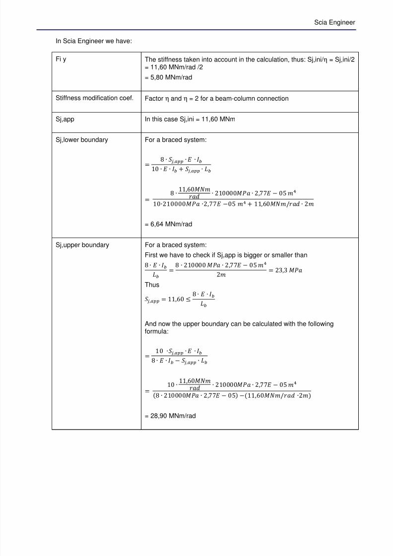
In Scia Engineer we have:
Fi y The stiffness taken into account in the calculation, thus: Sj,ini/ η = Sj,ini/2= 11,60 MNm/rad /2
= 5,80 MNm/rad
Stiffness modification coef. Factor η and η = 2 for a beam-column connection
Sj,app In this case Sj,ini = 11,60 MNm
Sj,lower boundary For a braced system:
= n ∙ œ̃ ,¤ ∙ ∙ ¿510 ∙ ∙ ¿5 + œ̃ ,¤ ∙ ‚5
= n ∙ 11,E0hmFAx ∙ 210000hzA ∙ 2, − 0& Fq10∙210000hzA ∙2, −0& Fq + 11,E0hmFkAx ∙ 2F
= 6,64 MNm/rad
Sj,upper boundary For a braced system:
First we have to check if Sj,app is bigger or smaller than
n ∙ ∙ ¿5‚5
= n ∙ 210000 hzA ∙ 2, − 0& Fq2F = 23,3 hzA
Thus
œ̃ ,¤ = 11,E0 n ∙ ∙ ¿5‚5
And now the upper boundary can be calculated with the followingformula:
= 10 ∙œ̃ ,¤ ∙ ∙ ¿5n ∙ ∙ ¿5 − œ̃ ,¤ ∙ ‚5
= 10 ∙11,E0hmF
Ax ∙ 210000hzA ∙ 2, − 0& Fq
n ∙ 210000hzA ∙ 2, − 0& −11,E0hmFkAx ∙2F
= 28,90 MNm/rad

7/23/2019 Calcul Connection in Scia.pdf
http://slidepdf.com/reader/full/calcul-connection-in-sciapdf 62/89
And now Sj,ini will be in between the two boundaries on the graph also:

7/23/2019 Calcul Connection in Scia.pdf
http://slidepdf.com/reader/full/calcul-connection-in-sciapdf 63/89
Scia Engineer
6. Calculation of welds
6.1. Default method
The default values for the double fillet welds to the beam flange af and for the double fillet welds to thebeam web aw, are as follows:
With: af The throat thickness of weld at beam flange (fillet weld)
aw The throat thickness of weld at beam web (fillet weld)
tfb The thickness of the beam flange
twb The thickness of the beam web
In the example CON_004.esa:
tfb = 9,2 mmtwb = 5,9 mm
And the material S235 has been used. So:
af > 0,5 tfb = 4,6 mm
af will be taken as 5 mm
In Scia Engineer:
aw > 0,5 twb = 2,95 mm
aw will be taken as 3 mm
7/23/2019 Calcul Connection in Scia.pdf
http://slidepdf.com/reader/full/calcul-connection-in-sciapdf 64/89
In Scia Engineer:
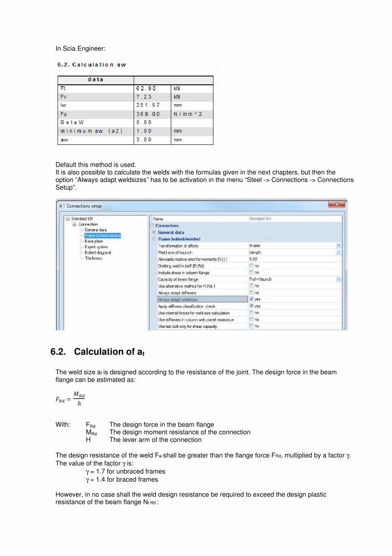
Default this method is used.It is also possible to calculate the welds with the formulas given in the next chapters, but then theoption “Always adapt weldsizes” has to be activation in the menu “Steel -> Connections -> ConnectionsSetup”.
6.2. Calculation of af
The weld size af is designed according to the resistance of the joint. The design force in the beamflange can be estimated as:
= ho
With: FRd The design force in the beam flangeMRd The design moment resistance of the connectionH The lever arm of the connection
The design resistance of the weld Fw shall be greater than the flange force FRd, multiplied by a factor γ .
The value of the factor γ is:
γ = 1.7 for unbraced frames
γ = 1.4 for braced frames
However, in no case shall the weld design resistance be required to exceed the design plasticresistance of the beam flange Nt.Rd :

7/23/2019 Calcul Connection in Scia.pdf
http://slidepdf.com/reader/full/calcul-connection-in-sciapdf 65/89
Scia Engineer
m8, = ∙ 5 ∙ 5
With bf The beam flange widthtfb The beam flange thicknessfyb The yield strength of the beam
So, we have
Fw = min ( Nt.Rd, γ FRd)
The weld size design for af:
A À ∙ a ∙ ¡a š ∙ ∙ √ 2
With Fw The design resistance of the weldbw The beam flange widthfu The ultimate tensile strength of the weaker part
βW The correlation factor
γ Mw The partial safety factor for welds
6.3. Calculation of aw
For all possible bolt groups, the maximum tension pro unit length is calculated.The tension pro unit length is (Fi + Fi+1)/l2.l2 is taken as the effective length of non-circular pattern for the considered bolt group.
On the weld 2 x l2 x a2, the normal force N (=Fi + Fi+1) and the shear force D is acting. The shear forceD is taken as that part of the maximum internal shear force on the node that is acting on the bolt rows iand i+1.To determine the weld size a 2 in a connection, we use a iterative process with a 2 as parameter until theVon Mises rules is respected:
7/23/2019 Calcul Connection in Scia.pdf
http://slidepdf.com/reader/full/calcul-connection-in-sciapdf 66/89
With fu the ultimate tensile strength of the weaker part
βW The correlation factor
γ Mw The partial safety factor for weldsA 2 a2 I2
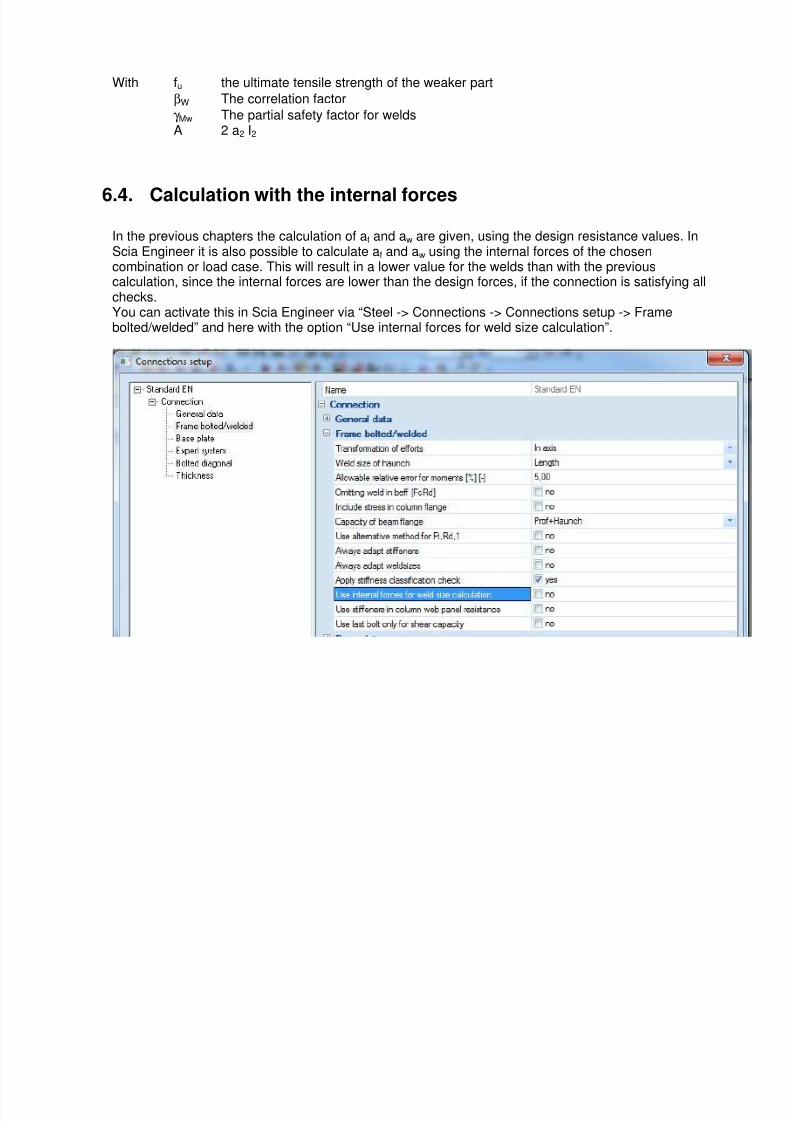
6.4. Calculation with the internal forces
In the previous chapters the calculation of af and aw are given, using the design resistance values. InScia Engineer it is also possible to calculate af and aw using the internal forces of the chosencombination or load case. This will result in a lower value for the welds than with the previouscalculation, since the internal forces are lower than the design forces, if the connection is satisfying allchecks.You can activate this in Scia Engineer via “Steel -> Connections -> Connections setup -> Framebolted/welded” and here with the option “Use internal forces for weld size calculation”.
7/23/2019 Calcul Connection in Scia.pdf
http://slidepdf.com/reader/full/calcul-connection-in-sciapdf 67/89
Scia Engineer
7. Ductility class
7.1. Ductility classes
The following classification is valid for joints:
Class 1 joint: Mj,Rd is reached by full plastic redistribution of the internal forces within the joints and asufficiently good rotation capacity is available to allow a plastic frame analysis and design.
Class 2 joint: Mj,Rd is reached by full plastic redistribution of the internal forces within the joints but therotational capacity is limited. An elastic frame analysis possibly combined with a plastic verification ofthe joints has to be performed. A plastic frame analysis is also allowed as long as it does not result in atoo high required rotation capacity of the joints where the plastic hinges are likely to occur.
Class 3 joint: brittle failure (or instability) limits the moment resistance and does not allow a fullredistribution of the internal forces in the joints. It is compulsory to perform an elastic verification of the joints unless it is shown that no hinge occurs in the joint locations.
From this description it is clear that it is better to modell a joint as a ductile joint. In this case, whenfailure appears, the load can be transferred to other parts of the joint and you can see that it is going tobrake slowly: you can see that the column web is yieling for example. If you have a brittle failure mode(non-ductile) the connection will brake immediately when reaching the failure mode.
7.2. Ductility classification for bolted joints
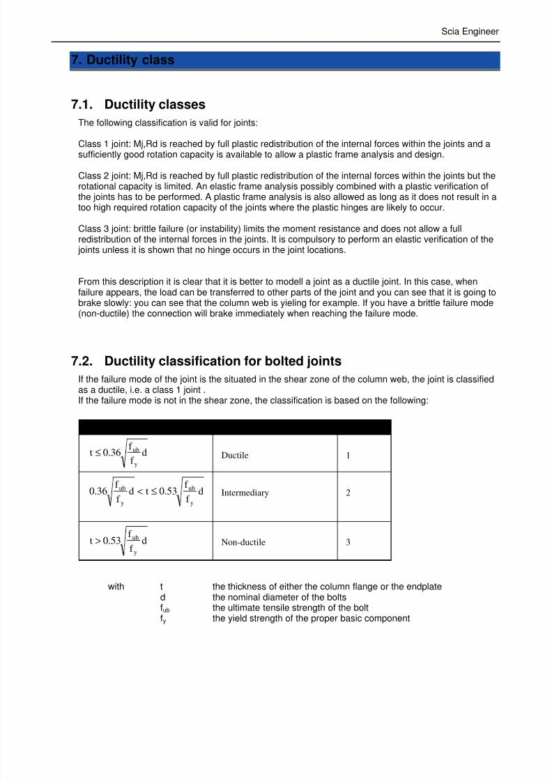
If the failure mode of the joint is the situated in the shear zone of the column web, the joint is classifiedas a ductile, i.e. a class 1 joint .If the failure mode is not in the shear zone, the classification is based on the following:
Classification by ductility Class
df
f 36.0t
y
ub≤ Ductile 1
df
f 53.0td
f
f 36.0
y
ub
y
ub ≤<
Intermediary 2
df
f 53.0t
y
ub> Non-ductile 3
with t the thickness of either the column flange or the endplated the nominal diameter of the boltsfub the ultimate tensile strength of the boltfy the yield strength of the proper basic component
7/23/2019 Calcul Connection in Scia.pdf
http://slidepdf.com/reader/full/calcul-connection-in-sciapdf 68/89
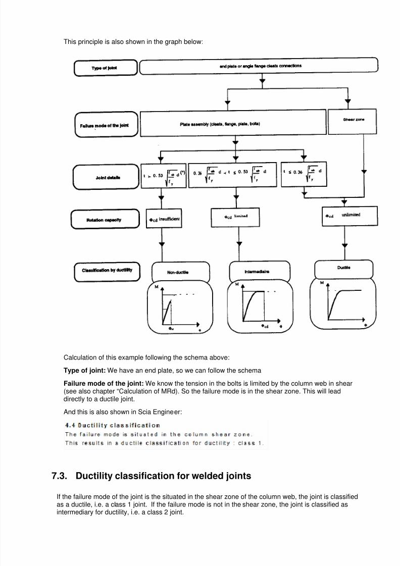
This principle is also shown in the graph below:
Calculation of this example following the schema above:
Type of joint: We have an end plate, so we can follow the schema
Failure mode of the joint: We know the tension in the bolts is limited by the column web in shear(see also chapter “Calculation of MRd). So the failure mode is in the shear zone. This will lead
directly to a ductile joint.
And this is also shown in Scia Engineer:
7.3. Ductility classification for welded joints
If the failure mode of the joint is the situated in the shear zone of the column web, the joint is classifiedas a ductile, i.e. a class 1 joint. If the failure mode is not in the shear zone, the joint is classified asintermediary for ductility, i.e. a class 2 joint.
7/23/2019 Calcul Connection in Scia.pdf
http://slidepdf.com/reader/full/calcul-connection-in-sciapdf 69/89
Scia Engineer
8. Extra options in Scia Engineer
8.1. RHS beam
In Scia Engineer it is possible to use an RHS
beam and make a between this beam and a I orH column. For more info about this topic, werefer to Ref.[2].
A connection with an RHS beam can be found inexample CON_005.esa, node N7.
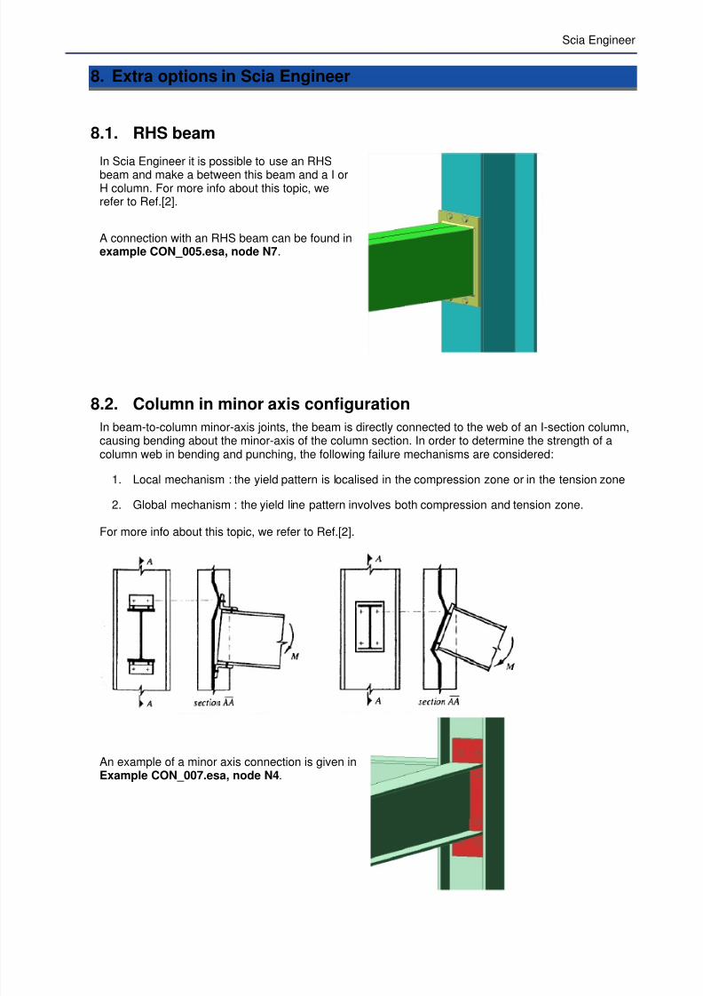
8.2. Column in minor axis configuration
In beam-to-column minor-axis joints, the beam is directly connected to the web of an I-section column,causing bending about the minor-axis of the column section. In order to determine the strength of acolumn web in bending and punching, the following failure mechanisms are considered:
1. Local mechanism : the yield pattern is localised in the compression zone or in the tension zone
2. Global mechanism : the yield line pattern involves both compression and tension zone.
For more info about this topic, we refer to Ref.[2].
An example of a minor axis connection is given inExample CON_007.esa, node N4.

7/23/2019 Calcul Connection in Scia.pdf
http://slidepdf.com/reader/full/calcul-connection-in-sciapdf 70/89
8.3. Base plate connections: shear iron, flange wideners
In a column base, 2 connection deformabilities need to be distinguished:
1. the deformability of the connection between the column and the concrete foundation
2. the deformability of the connection between the concrete foundation and the soil.
In the Frame Connect base plate design, the column-to-concrete “connection’ is considered.
For more info about base plate design (shear irons, etc…), we refer to Ref.[2]. An example of a baseplate connection in Scia Engineer is given in Example CON_005.esa, Node N9.
8.4. Extra options for the calculation of connections
In Scia Engineer it is possible to perform an overall check for multiple connections at the same time.For example we can have a look at example CON_008.esa. In this project several connections have
been input.
7/23/2019 Calcul Connection in Scia.pdf
http://slidepdf.com/reader/full/calcul-connection-in-sciapdf 71/89
Scia Engineer
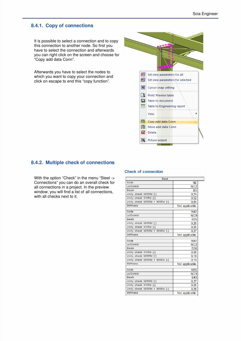
8.4.1. Copy of connections
It is possible to select a connection and to copythis connection to another node. So first youhave to select the connection and afterwardsyou can right click on the screen and choose for
“Copy add data Conn”.
Afterwards you have to select the nodes towhich you want to copy your connection andclick on escape to end this “copy function”.
8.4.2. Multiple check of connections
With the option “Check” in the menu “Steel ->Connections” you can do an overall check forall connections in a project. In the previewwindow, you will find a list of all connections,with all checks next to it.
7/23/2019 Calcul Connection in Scia.pdf
http://slidepdf.com/reader/full/calcul-connection-in-sciapdf 72/89
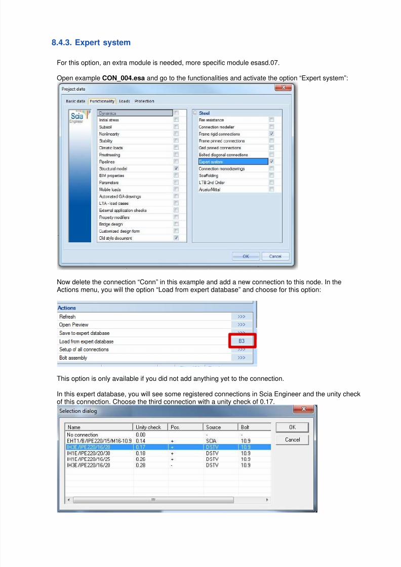
8.4.3. Expert system
For this option, an extra module is needed, more specific module esasd.07.
Open example CON_004.esa and go to the functionalities and activate the option “Expert system”:
Now delete the connection “Conn” in this example and add a new connection to this node. In theActions menu, you will the option “Load from expert database” and choose for this option:
This option is only available if you did not add anything yet to the connection.
In this expert database, you will see some registered connections in Scia Engineer and the unity checkof this connection. Choose the third connection with a unity check of 0.17.
7/23/2019 Calcul Connection in Scia.pdf
http://slidepdf.com/reader/full/calcul-connection-in-sciapdf 73/89
Scia Engineer
Now this connection will be input on the node and you can adapt this default connection afterwards.
When selecting a connection, you can choose for the option “Save to expert database” and save yourconnection in this database and use it again in another project.
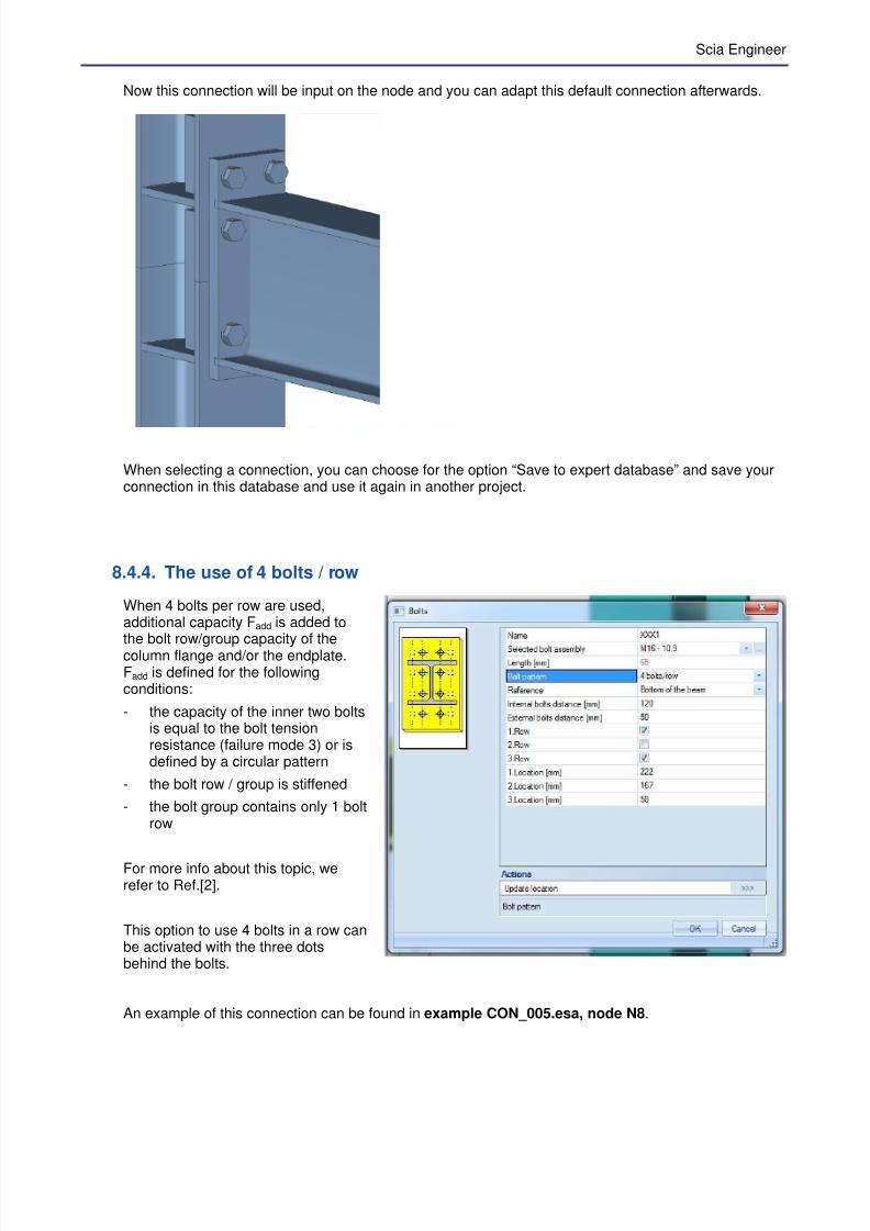
8.4.4. The use of 4 bolts / row
When 4 bolts per row are used,additional capacity Fadd is added tothe bolt row/group capacity of thecolumn flange and/or the endplate.Fadd is defined for the followingconditions:
- the capacity of the inner two boltsis equal to the bolt tensionresistance (failure mode 3) or isdefined by a circular pattern
- the bolt row / group is stiffened
- the bolt group contains only 1 boltrow
For more info about this topic, werefer to Ref.[2].
This option to use 4 bolts in a row canbe activated with the three dotsbehind the bolts.
An example of this connection can be found in example CON_005.esa, node N8.

7/23/2019 Calcul Connection in Scia.pdf
http://slidepdf.com/reader/full/calcul-connection-in-sciapdf 74/89
8.4.5. Monodrawings
It is possible to make automatic connection drawings in Scia Engineer. To use this option, it isnecessary to select the functionality “Connection monodrawings”:
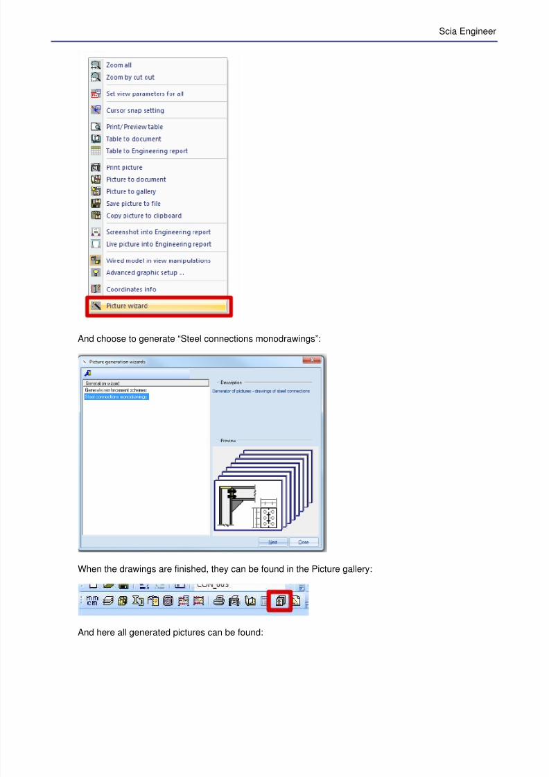
When this option is activated and you have one or more connections in the project, you can right clickon the screen and choose for the “Picture wizard”:
7/23/2019 Calcul Connection in Scia.pdf
http://slidepdf.com/reader/full/calcul-connection-in-sciapdf 75/89
Scia Engineer
And choose to generate “Steel connections monodrawings”:
When the drawings are finished, they can be found in the Picture gallery:
And here all generated pictures can be found:

7/23/2019 Calcul Connection in Scia.pdf
http://slidepdf.com/reader/full/calcul-connection-in-sciapdf 76/89
8.4.6. Options in the properties window
Load case/Combination
AllAll combinations are checked.
Extreme N,V,MIn this case only 6 combinations are checked, more specific the combinations results in the biggestpositive and biggest negative value for N, V and M.Those biggest values are not combined together, but always with the real internal forces. This checkwill go a bit faster than when choosing for “All”.
With the option All, it is possible that not the biggest moment or biggest normal check will cause thebiggest check, but a combination of the two smaller values in another combination. This check will notbe shown when choosing for “Extreme N,V,M”.

7/23/2019 Calcul Connection in Scia.pdf
http://slidepdf.com/reader/full/calcul-connection-in-sciapdf 77/89
Scia Engineer
9. Welded connections
In this chapter we will show the calculation of a welded connectionusing example CON_005.esa, node N3.
The calculation is done with the Safety factors according the EN1993-1-8 (Ref.[1]) and the following internal forces:
A negative moment will result in tension at the top flange of the beam.
Calculation Vwp,Rd : Column web panel in shear
0M
vcy
Rd,wp3
'Af 9.0Vγ
=
When a web doubler is used:
kN
mm A
mm A
A
t r t bt A A
t b A A
vc
vc
vc
f w f vc
ssvcvc
77,7270.13
59192350.9RdVwp,
²59195.101724113'
²4113
18)2425.10(18280213140
)2(2
'
=⋅
⋅⋅=
=⋅+=
=
⋅++⋅⋅−=
++−=
+=
And the same is shown in Scia Engineer:

7/23/2019 Calcul Connection in Scia.pdf
http://slidepdf.com/reader/full/calcul-connection-in-sciapdf 78/89
Calculation Fc,wc,Rd : Column web in compression
( )
kN kN F
A
t b
mmb
r t at b
mmt t
f t bF
Rd wcc
vc
wceff
eff
fc fbeff
wwc
M
ywceff
Rd wcc
77,7386740,1
23575,1566,25279,0
79.0
'3.11
1
66,252)2418(59222.17
522
75.155.105.15.1
,,
21
1
0
,,
==⋅⋅⋅
=
=
+
=
=
=++⋅+=
+++=
=⋅==
=
ρ
ρ ρ
γ
ρ
And in Scia Engineer:
Calculation Fc,fb,Rd : Beam flange in compression
kN kNmm
F
kNm M
M
t h
M F
Rd fbc
M
Rd pl
Rd c
fbb
Rd c
Rd fbc
12292.17550
655000
6550.1
655
,,
0
,
,
,
,,
=−
=
===
−=
γ
In Scia Engineer:

7/23/2019 Calcul Connection in Scia.pdf
http://slidepdf.com/reader/full/calcul-connection-in-sciapdf 79/89
Scia Engineer
Calculation Ft,fc,Rd : Column flange in bending
kN F
f t kt r t F
Rd fcc
M
ywc
fccwc Rd fcc
7450.1
23520.17)18172425.10(
)72(
,,
0
,,
=⋅
⋅⋅+⋅+=
++=γ
In Scia Engineer:
Calculation Ft,wc,Rd : Column web in tension
( )
kN F
A
t b
mmb
r t at b
mmt t
f t bF
Rd wct
vc
wceff
eff
fc fbeff
wwc
M
ywceff
Rd wct
7050.1
2357.1425281.0
81.0
'3.11
1
252)2418(59222.17
522
7.145.104.14.1
,,
21
1
0
,,
=⋅⋅⋅
=
=
+
=
=
=++⋅+=
+++=
=⋅==
=
ρ
ρ ρ
γ
ρ
In Scia Engineer:
Calculation MRd : Design moment resistance
705 kN x 0.532 m = 375 kNm
In Scia Engineer:
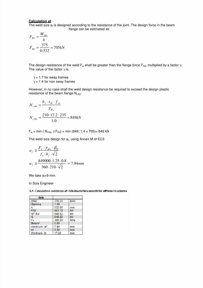
7/23/2019 Calcul Connection in Scia.pdf
http://slidepdf.com/reader/full/calcul-connection-in-sciapdf 80/89
Calculation afThe weld size af is designed according to the resistance of the joint. The design force in the beam
flange can be estimated as:
The design resistance of the weld Fw shall be greater than the flange force FRd, multiplied by a factor γ .
The value of the factor γ is:
γ = 1.7 for sway frames
γ = 1.4 for non sway frames
However, in no case shall the weld design resistance be required to exceed the design plasticresistance of the beam flange Nt.Rd :
kN N
f t b N
Rd t
M
yb fb f
Rd t
8490.1
2352.17210,
,
0
=⋅⋅
=
⋅⋅=
γ
Fw = min ( Nt.Rd, γ FRd) = min (849, 1.4 x 705)= 849 kN
The weld size design for af, using Annex M of EC3
mma
b f
F
a
f
f u
W Mww
f
94.72210360
8.025.1849000
2
=⋅⋅
⋅⋅≥
⋅⋅
⋅⋅
≥
β γ
We take af=9 mm.
In Scia Engineer
kN F
h
M F
Rd
Rd
Rd
705532.0
375==
=
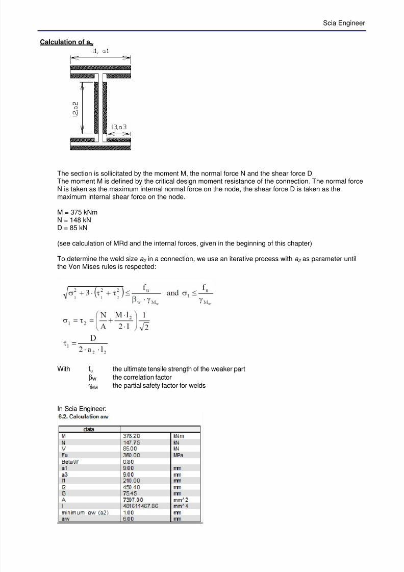
7/23/2019 Calcul Connection in Scia.pdf
http://slidepdf.com/reader/full/calcul-connection-in-sciapdf 81/89
Scia Engineer
Calculation of aw
The section is sollicitated by the moment M, the normal force N and the shear force D.The moment M is defined by the critical design moment resistance of the connection. The normal forceN is taken as the maximum internal normal force on the node, the shear force D is taken as the
maximum internal shear force on the node.
M = 375 kNmN = 148 kND = 85 kN
(see calculation of MRd and the internal forces, given in the beginning of this chapter)
To determine the weld size a 2 in a connection, we use an iterative process with a 2 as parameter untilthe Von Mises rules is respected:
With fu the ultimate tensile strength of the weaker part
βW the correlation factor
γ Mw the partial safety factor for welds
In Scia Engineer:
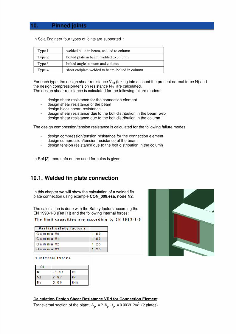
7/23/2019 Calcul Connection in Scia.pdf
http://slidepdf.com/reader/full/calcul-connection-in-sciapdf 82/89
10. Pinned joints
In Scia Engineer four types of joints are supported :
Type 1 welded plate in beam, welded to column
Type 2 bolted plate in beam, welded to columnType 3 bolted angle in beam and column
Type 4 short endplate welded to beam, bolted in column
For each type, the design shear resistance VRd (taking into account the present normal force N) andthe design compression/tension resistance NRd are calculated.The design shear resistance is calculated for the following failure modes:
- design shear resistance for the connection element- design shear resistance of the beam- design block shear resistance- design shear resistance due to the bolt distribution in the beam web
- design shear resistance due to the bolt distribution in the column
The design compression/tension resistance is calculated for the following failure modes:
- design compression/tension resistance for the connection element- design compression/tension resistance of the beam- design tension resistance due to the bolt distribution in the column
In Ref.[2], more info on the used formulas is given.
10.1. Welded fin plate connection
In this chapter we will show the calculation of a welded finplate connection using example CON_009.esa, node N2.
The calculation is done with the Safety factors according theEN 1993-1-8 (Ref.[1]) and the following internal forces:
Calculation Design Shear Resistance VRd for Connection Element
Transversal section of the plate:2
plplpl m003912.0th2A =⋅⋅= (2 plates)
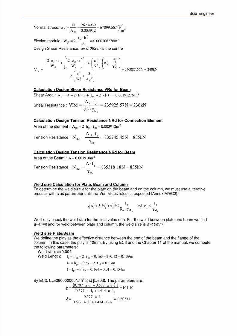
7/23/2019 Calcul Connection in Scia.pdf
http://slidepdf.com/reader/full/calcul-connection-in-sciapdf 83/89
Scia Engineer
Normal stress: 2pl
Nm
N667.67099003912.0
4939.262
A
N===σ
Flexion module: 3
2pl
pl m000106276.06
ht2W
pl
=⋅
⋅=
Design Shear Resistance: a= 0.082 m is the centre
kN240N66.240087
A
3
W
a2
f
N
a4
W
a2
W
a2
V
2
pl
2
2
2
M
2y2
N2
22
pl
N
pl
N
Rd
pl
0
==
+⋅
γ
−σ⋅
⋅−
⋅σ⋅+
⋅σ⋅−
=
Calculation Design Shear Resistance VRd for Beam
Shear Area : ( ) 2f wf v m00191276.0tr2ttb2AA =⋅⋅++⋅⋅−=
Shear Resistance : kN236N57.2359253
f AVRd
0M
yv==
γ ⋅
⋅=
Calculation Design Tension Resistance NRd for Connection Element
Area of the element :2
plplpl m003912.0th2A =⋅⋅=
Tension Resistance : kN835N45.835745f A
N
0M
ypl
Rd ==γ
⋅=
Calculation Design Tension Resistance NRd for Beam
Area of the Beam : 2m003910.0A =
Tension Resistance : kN835N18.835318f A
N
0M
y
Rd ==γ
⋅=
Weld size Calculation for Plate, Beam and ColumnTo determine the weld size a for the plate on the beam and on the column, we must use a iterativeprocess with a as parameter until the Von Mises rules is respected (Annex M/EC3):
( )ww
211
M
u1
Mw
u222 f and
f 3
γ ≤σ
γ ⋅β≤τ+τ⋅+σ
We’ll only check the weld size for the final value of a . For the weld between plate and beam we finda=4mm and for weld between plate and column, the weld size is a=10mm .
Weld size Plate/BeamWe define the play as the effective distance between the end of the beam and the flange of thecolumn. In this case, the play is 10mm. By using EC3 and the Chapter 11 of the manual, we computethe following parameters:
Weld size: a=0.004Weld Length: m139.012.02163.0t2hl plpl1 =⋅−=⋅−=
m13.0t2Playbl plpl2 =⋅−−=
m154.001.0164.0Playll pl =−=−=
By EC3: fuw=360000000N/m2 and βw=0.8. The parameters are:
( )10.104
la414.1la577.0
lla577.0la707.0g
21
11 =⋅⋅+⋅⋅
⋅⋅⋅+⋅⋅=
30377.0la414.1la577.0
la577.0
21
1 =⋅⋅+⋅⋅
⋅⋅=δ
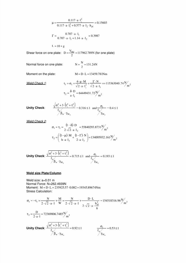
7/23/2019 Calcul Connection in Scia.pdf
http://slidepdf.com/reader/full/calcul-connection-in-sciapdf 84/89
15603.0hla577.0la117.0
la117.0
pl221
2
1 =⋅⋅⋅+⋅⋅
⋅⋅=µ
3987.0la14.1la707.0
la707.0
21
1 =⋅⋅+⋅⋅
⋅⋅=Γ
g10L +=
Shear force on one plate: N789.1179622
VD Rd == (for one plate)
Normal force on one plate: N24.1312
NN ==
Moment on the plate: Nm781.13459LDM =⋅=
Weld Check 1:2
1211
mN74.115363040
la2
N
la2
M6
1
==⋅⋅
⋅Γ +
⋅⋅
⋅µ⋅=σ=τ
21
2m
N72.64449431laD =⋅⋅δ=τ
Unity Check:( )
14.0f
and 1316.0f
3
ww
211
M
u
1
Mw
u
222
≤=
γ
σ≤=
γ ⋅β
τ+τ⋅+σ
Weld Check 2 :( )
2
2
11m
N8731.55840293la22
D1=
⋅⋅⋅
⋅δ−=τ=σ
( ) ( )2
222 m
N161.134095932la2
N1
lah
M1
=
⋅⋅
⋅Γ −
+⋅⋅
⋅µ−
=τ
Unity Check:( )
1193.0f
and 1715.0f
3
ww
211
M
u
1
Mw
u
222
≤=
γ
σ≤=
γ ⋅β
τ+τ⋅+σ
Weld size Plate/Column
Weld size: a=0.01 m
Normal Force: N=262.4939NMoment: Nm89674.19345082.057.235925LDM =⋅=⋅=
Stress Calculation:
22pl
11m
N96.154518316
6
ha22
LD
la22
N
W
M
la22
N=
⋅⋅⋅
⋅+
⋅⋅⋅=+
⋅⋅⋅=τ−=σ
22m
N7485.72369806la2
D=
⋅⋅=τ
Unity Check:( )
192.0f
3
w
211
Mw
u
222
≤=
γ ⋅β
τ+τ⋅+σ 153.0
f wM
u
1 ≤=
γ
σ

7/23/2019 Calcul Connection in Scia.pdf
http://slidepdf.com/reader/full/calcul-connection-in-sciapdf 85/89
Scia Engineer
10.2. Bolted fin plate connection
In this chapter we will show the calculation of a bolted finplate connection using example CON_010.esa, node N7.
Calculation Design Shear Resistance VRd forConnection Element
Transversal section of the plate:2m004512.0012.0188.02th2A =⋅⋅=⋅⋅= (2 plates)
Normal Stress: 2Nm
N8395.58176004512.0
4939.262
A
N===σ
Flexion Module : 32
m000141376.06
ht2W =
⋅⋅=
Bolt Centre : a=0.0995m
Design Shear Resistance:
kN266N015.266422
A
3
W
a2
f
N
a4
W
a2
W
a2
V
22
2
2
M
2
y2
N2
22
NN
Rd
0
==
+⋅
γ −σ⋅
⋅−
⋅σ⋅+
⋅σ⋅−
=
Calculation Design Shear Resistance VRd for Beam
Shear Area : ( ) 2f wf v m00191276.0tr2ttb2AA =⋅⋅++⋅⋅−=
Net Area : m56.001689.0dt2AA 0wvnet =⋅⋅−=
For the calculation of VRd in the beam, we use Av because 2v
u
y
net m00124860.0Af
f A =⋅≥
Shear Resistance: kN236N57.2359253
f AVRd
0M
yv==
γ ⋅
⋅=
Calculation Design Tension Resistance NRd for Connection Element
Area : 2m004512.0ht2A =⋅⋅=
Net Area : 20net m003648.0d2t2AA =⋅⋅⋅−=
Tension Resistance :
γ
⋅⋅
γ
⋅=
1
net
0 M
u
M
y
Rd
f A9.0,
f AminN ( ) kN963N27.96392781.1074501,27.963927min ===
Calculation Design Tension Resistance NRd for Beam
Area :2m003910.0A =
Net Area :2
0net m0036868.0dt2AA =⋅⋅−=
Tension Resistance :
γ
⋅⋅
γ
⋅=
1
net
0 M
u
M
y
Rd
f A9.0,
f AminN
( ) kN836N18.83531818.1085930,18.835318min ===

7/23/2019 Calcul Connection in Scia.pdf
http://slidepdf.com/reader/full/calcul-connection-in-sciapdf 86/89
Calculation Design Shear Resistance VRd for Bolt in BeamThe calculation of the shear resistance for bolt in beam is based on the following equation to be solve
0Qn
N
nI
dNa2V
I
da
I
ca
n
1V 2
2
2
p
Rd2
p
22
2
p
22
2
2
Rd=−+
⋅
⋅⋅⋅⋅+
⋅+
⋅+⋅
Where : 0.0995ma = 0.094mb = 0.0655mc = 0.07md = 24
1i
22ip m036761.066.95rI ∑ ∑ ===
=
beam,Rd,bplate,Rd,bRd,v F;Fmin,F2minQ ⋅= =31740.8256N for two plates, where
• kN1.30N30144Af 6.0
FMb
sub
VdR
==γ
⋅⋅=
• kN7.31N8256.31740tdf 5.2
FMb
up
Beam,Rd,b ==γ
⋅⋅⋅α⋅=
444.01;
f
f ;
4
1
d3
p;
d3
eminwith
u
ub
0
1
0
1p =
−=α
• N712.122867tdf 5.2
FMb
plup
plate,Rd,b =γ
⋅⋅⋅α⋅=
444.01;f
f ;
4
1
d3
p;
d3
eminwith
u
ub
0
1
0
1p =
−=α
By solving the second-degree equation, we find kN9.67N89.67907VRd ==
Calculation Design Block Shear ResistanceThe design value of the effective resistance to block shear is determined by the following expression :
eff ,veff v,
M
eff ,vy
Rd,eff LtA with3
Af V
0
⋅=γ ⋅
⋅=
We determined the effective shear area Av,eff as follows :
m049.0a1 = m155.0a 2 = m051.0a 3 =
m14.0aahL 21v =−−=
( )
( ) m24.02849.0;24.0min
f
f dnaaL;aaLminL
y
u031v31v3
==
⋅⋅−++++=
( ) m049.0d5;aminL 011 =⋅=
( )
boltrows2for2.5k with
m1685.0f
f dk aL
y
u022
=
=⋅⋅−=
( ) m24.0L;LLLminL 321veff ,v =++=
2eff ,v m001488.0A =
kN185N40.1835343
Af V
0M
eff ,vy
Rd,eff ==γ ⋅
⋅=

7/23/2019 Calcul Connection in Scia.pdf
http://slidepdf.com/reader/full/calcul-connection-in-sciapdf 87/89
Scia Engineer
10.3. Bolted cleat connection
In this chapter we will show the calculation of a bolted cleatconnection using example CON_011.esa, node N2.
To determine the design shear resistance for bolts in the flange ofthe column, we use a iterative process with hD as parameter untilwe reach a equilibrium :
γ γ =σ
00 M
cor,y
M
beam,y
D
f ,
f min
We’ll only consider the check for the final value of hD. We have the following data:m008.0r = m03.0a = m006.0s =
m0128436.0s577.1r4227.0b =⋅+⋅= m0028436.0Playbbs =−=
m011.0h D = 22
ipD m029194.0rID== ∑
We compute: 0951.1anI
aK
2
pD
=⋅−
=
We define x j=0.03m and z j=0.165m respectively as the maximum horizontal distance between boltsand d and the maximum vertical distance between the bolts and d. It corresponds to the further bolts
how is submitted to the higher force.
( ) 5.0xaKn
1A j =−⋅+= 18069.0zKB j =⋅=
N16224Fn4.1
N1F,FminQ
Rd,tRd,vRd,b =
⋅⋅−⋅= where:
N16224Af 6.0
FMb
subcor,V
dR=
γ
⋅⋅= and N24336
Af 9.0F
Mb
subRd,t =
γ
⋅⋅=
N2.22187tdf 5.2
FMb
corup
cor,Rd,b =γ
⋅⋅⋅α⋅=
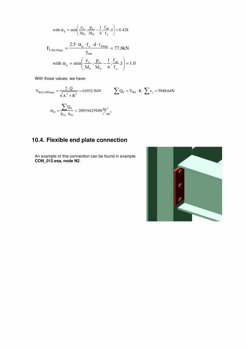
7/23/2019 Calcul Connection in Scia.pdf
http://slidepdf.com/reader/full/calcul-connection-in-sciapdf 88/89
428.01;f
f ;
4
1
d3
p;
d3
eminwith
u
ub
0
1
0
1p =
−=α
kN8.77tdf 5.2
FMb
flangeup
flange,Rd,b =γ
⋅⋅⋅α⋅=
0.11;f f ;
41
d3p;
d3eminwith
u
ub
0
1
0
1p =
−=α
With those values, we have:
N94.61032
BA
Q2V
22ColFlange,Rd =
+
⋅= ∑ ∑ =⋅⋅= N64.5948zKVQ jRdh
2DD
h
Dm
N89.209194259bh
Q=
⋅=σ ∑
10.4. Flexible end plate connection
An example of this connection can be found in exampleCON_012.esa, node N2.

7/23/2019 Calcul Connection in Scia.pdf
http://slidepdf.com/reader/full/calcul-connection-in-sciapdf 89/89
Scia Engineer
References and literature
[1] Eurocode 3
Design of steel structures
Part 1 - 8 : Design of joints
EN 1993-1-8: 2005
[2] Scia Engineer Steel_Connections_Theory_enu.pdf
Theoretical Background of Scia Engineer
Release : 13.0