calcs 14-266-b-nghs arthur 26 september 2015 purlin support steel – grids 4 and 5 ... wall area =...
TRANSCRIPT

Structural Calculations
Project Napier Girls High School Performing Arts Building (Arthur Building)
Project Number 14‐266
Document Control
Date Version Extent of Revision Status
21 September 2015 A Original Review
26 September 2015 B Skectches Incorporated Building Consent
Calculations prepared by Tim Pike Sigma Consulting Engineers Ltd CPEng 161118

Table of Contents Introduction ............................................................................................................................................................... 2
Scope of Assessment ................................................................................................................................................. 2
Design Criteria ............................................................................................................................................................ 3
Wind Forces ............................................................................................................................................................... 3
Seismic Design Actions ‐ Superstructure ................................................................................................................... 3
Plan ............................................................................................................................................................................ 4
Transverse Portal Frame – Grid 1 .............................................................................................................................. 8
Portal Frame – Grids 2, 3, 4, 5 ................................................................................................................................... 9
Purlins ...................................................................................................................................................................... 10
Studs ........................................................................................................................................................................ 10
Longitudinal Portals ................................................................................................................................................. 11
East Wall – Window Framing (Grid 5) ...................................................................................................................... 12
South Wall – Window Framing (Grids H and I) ........................................................................................................ 13
Eaves Beams to Support Wall Posts ......................................................................................................................... 14
North Wall – Door Framing ...................................................................................................................................... 15
Secondary Purlin Support Steel – Grid 2 .................................................................................................................. 16
Secondary Purlin Support Steel – Grid 3 .................................................................................................................. 17
Secondary Purlin Support Steel – Grids 4 and 5 ...................................................................................................... 18
Column and Post Arrangement ............................................................................................................................... 19
Suspended Parapet Wall .......................................................................................................................................... 21
Classroom 2 Eaves Structure ................................................................................................................................... 23
Roof Bracing ............................................................................................................................................................. 26
Retaining Wall to South Face ................................................................................................................................... 27
Portal Column Foundations ..................................................................................................................................... 28
Foundations to Columns at Grids E1, E2, I1, I2, H4, H5, G2, G3, C4, F4 .................................................................. 29
Foundations to Columns at Grids C5, F5 .................................................................................................................. 29
Base Fixing to 125x125x5.0 SHS Posts ..................................................................................................................... 29
Plan .......................................................................................................................................................................... 30
Durability Statement ................................................................................................................................................ 31
Appendices............................................................................................................................................................... 32
Client Napier Girls High School Project No 14 – 266
Project Performing Arts Building Revision B
Location 6 Clyde Road Napier Hill Date 26 Sept 2015
Designer JDTA and MPA Page No 01

Introduction Part of existing building superstructure is to be demolished and a replacement superstructure built with similar footprint. RDCL have completed geotechnical investigations and report R150602065_01 dated 29 May 2015 applies. NCC considers the site to be in an “Extra High” wind zone to NZS 3604:2011. BRANZ consider the site to be in a “Medium” wind zone and Corrosion Zone D. Earthquake zone 3. RDCL consider the soil class to be “B” (rock). Investigations have confirmed that the foundation wall to the south face of the building, which retains hardfill and the concrete floor slab to the building, does not incorporate significant foundations and is considered to not be in compliance with the current building code.
Scope of Assessment
Portal frames
Gable wall structure
Longitudinal roof bracing
Longitudinal wall bracing
Eaves beams
Purlins
Retaining Wall
Foundations
Client Napier Girls High School Project No 14 – 266
Project Performing Arts Building Revision B
Location 6 Clyde Road Napier Hill Date 26 Sept 2015
Designer JDTA and MPA Page No 02

Design Criteria From AS/NZS 1170:
50 year design life for building
Importance level 2
APE = 1/500 ULS and 1/25 SLS
Wind Forces Region A7 V500 = 45 m/s; V25 = 37 m/s Terrain category 3 Mz = 0.83 Ms = 1.0 Mt = 1.0 Vd= 37.4 m/s Qu = 0.85 kPa and Qs = 0.57 kPa Cpe walls = +0.7 and ‐0.5 Roof pitch = 2 degrees; h/d = 0.4; Cpe roof = ‐0.5 say If Tc = 2.5 then Mz = 0.87 and v = 39.2 m/s and qu = 0.92 kPa Med wind speed = 37 m/s and High wind speed = 44 m/s Design for wind speed of 44 m/s and Qu = 1.2 kPa and Qs = 0.8 kPa
Seismic Design Actions ‐ Superstructure Subsoil class B Use 0.4 kPa dead load for roof + ceiling + services Use 0.4 kPa dead load for walls Roof area = 350m2 so G = 140 kN Wall area = 400m2 so G = 80 kN (half of wall area) Transverse loads resisted by portals on grids 1, 2/3, 4 and 5. 10 metre supported width, so some conservatism and inherent allowance for eccentricity. Longitudinal loads resisted by portals E1‐E2; A1‐A2; G4‐G5; D4‐D5; and B4‐B5. Ceiling/roof diaphragm to all spaces. Use NZS 3404:Part 1:1997 for steel design. Category 3 structure, µ = 1.25, Sp = 0.9. But can use Sp = 0.7 for category 3 members as the material, section geometry, member restraint and connection requirements of section 12 are complied with.
Client Napier Girls High School Project No 14 – 266
Project Performing Arts Building Revision B
Location 6 Clyde Road Napier Hill Date 26 Sept 2015
Designer JDTA and MPA Page No 03

Plan
Client Napier Girls High School Project No 14 – 266
Project Performing Arts Building Revision B
Location 6 Clyde Road Napier Hill Date 26 Sept 2015
Designer JDTA and MPA Page No 04

Client Napier Girls High School Project No 14 – 266
Project Performing Arts Building Revision B
Location 6 Clyde Road Napier Hill Date 26 Sept 2015
Designer JDTA and MPA Page No 05

Client Napier Girls High School Project No 14 – 266
Project Performing Arts Building Revision B
Location 6 Clyde Road Napier Hill Date 26 Sept 2015
Designer JDTA and MPA Page No 06

Client Napier Girls High School Project No 14 – 266
Project Performing Arts Building Revision B
Location 6 Clyde Road Napier Hill Date 26 Sept 2015
Designer JDTA and MPA Page No 07

Transverse Portal Frame – Grid 1 Supported width = 5 metres but use 10 metres Adopt roof area = (10m x 12m) = 120m2 so G = 48 kN per frame = 4.8 kN/m Q = 0.25 kPa = 2.5 kN/m but zero in combination with seismic forces Wall supported = 50m2 so G = 20 kN, apply as 1.2 kN/m to rafter So total load to rafter = 6.0 kN/m Total mass = 60 kN Portal Period: initial guess = 0.60 seconds 310UB40 trial section Z = 0.38 N = 1.0 R = 1.0 ULS and 0.25 SLS Ch(T) = 1.40 Therefore C(T) = 0.53 ULS and 0.13 SLS µ = 1.25 Sp = 0.7 kµ = 1.214 Cd (T) = C(T)*Sp/kµ = (0.53*0.7/1.214) = 0.31 (ULS) and 0.075 SLS W = 60kN F = 18.6kN ULS and 4.5 kN SLS d = 29mm (ULS) T = 2π ((60,000*0.0292)/(9.81*18,600*0.029))0.5 = 0.61 seconds OK Use T = 0.6 seconds Wind: Windward wall P = (0.85*2.0*10.0*0.7) = 11.9 kN ULS and 8.0 kN SLS Leeward wall P = (0.85*2.0*10.0*0.5) = 8.5 kN ULS 5.7 kN SLS Roof uplift = (10.0*0.85*0.5) = 4.25 kN/m ULS and 2.85 kN/m SLS Wind wall loads applied as point loads to eave since wall studs will be used, connected to an eaves beam Refer to SpaceGass12.21 analysis. Pinned bases.
Displacement Results Vertical midspan deflection (G only) = 17mm = span/600 Lateral displacement in SLS earthquake = 5mm = height/800 In SLS wind the horizontal displacement = 22mm and the vertical deflection = 9mm Accept. Strength Results Mmax = 75 kNm at eave (G+Q), check unrestrained columns using MemDes: ΦMbx = 111 kNm so OK Rafters will be OK as they are restrained by the purlins Mmax = 78 kNm at eave (G+E), unrestrained columns OK (see above) Mrafters = 40 kNm, bottom flange in tension so OK; bottom flange in compression for short length only so OK In wind case the column moment is less than for gravity or earthquake so is OK Rafters moment = 55 kNm for half span say; ΦMbx = 97 kNm so OK Concluded that 310UB40 portal is OK, with no lateral restraints to columns or rafters
Client Napier Girls High School Project No 14 – 266
Project Performing Arts Building Revision B
Location 6 Clyde Road Napier Hill Date 26 Sept 2015
Designer JDTA and MPA Page No 08

Portal Frame – Grids 2, 3, 4, 5
Supported width = 6.5 metres on grids 2, 3, 5; but 9.5 metres on grid 4 Heights are similar to the portal frame on grid 1, but with a reduced rafter span Supported area is less for seismic forces but similar for gravity and wind forces So use same forces and loads as for portal frame on grid 1 – loaded width 10 metres Displacement Results Vertical midspan deflection (G only) = 1.7mm Lateral displacement in SLS earthquake = 5mm = height/800 In SLS wind the horizontal displacement = 17mm and the vertical deflection = 9mm Accept. Strength Results Mmax = 75 kNm at eave (G+Q), check unrestrained columns using MemDes: ΦMbx = 111 kNm so OK Rafters will be OK as they are restrained by the purlins Mmax = 49 kNm at eave (G+E), unrestrained columns OK (see above) Mrafters = 49 kNm, bottom flange in tension so OK; bottom flange in compression for short length only so OK In wind case the column moment is similar as for earthquake so is OK Rafters moment = 55 kNm for half span say; ΦMbx = 97 kNm so OK Concluded that 310UB40 portal is OK, with no lateral restraints to columns or rafters
Client Napier Girls High School Project No 14 – 266
Project Performing Arts Building Revision B
Location 6 Clyde Road Napier Hill Date 26 Sept 2015
Designer JDTA and MPA Page No 09

Purlins Span = 11.5 metres Spacing = 1000mm G = 0.4 kN/m Q = 0.25 kN/m Wu = 0.85 kN/m Ws = 0.57 kN/m 1.2G+1.5Q = 0.85 kN/m 0.9G‐Wu = ‐0.5 kN/m Use DHS 300/15 purlins at 1000mm centres 2 rows of bracing to each span Alternatively use 450x63 hySPAN purlins at 600mm centres
Studs Non load bearing external walls Height = 4.4 metres See also NZS 3604:2011 table 8.4 Qu = 0.85 kPa and Qs = 0.57 kPa Assume 400mm centres Wu = 0.34 kN/m and Ws = 0.23 kN/m M* = 0.82 kNm 140x45 SG8: ΦMb = 1.65 kNm so OK Def = 13.6mm = span/323
Client Napier Girls High School Project No 14 – 266
Project Performing Arts Building Revision B
Location 6 Clyde Road Napier Hill Date 26 Sept 2015
Designer JDTA and MPA Page No 10

Longitudinal Portals Span = 11.4 metres (grids 1 – 3), height = 4.4 metres Supported width = 5 metres Each portal is to resist one‐quarter of the total building seismic load (conservative as there are 5 portals) G = 2.0 kN/m Q = 1.25 kN/m Wind: Windward wall P = (0.85*2.2*6.0*0.7) = 7.9 kN ULS and 5.3 kN SLS Leeward wall P = (0.85*2.2*6.0*0.5) = 5.6 kN ULS 3.8 kN SLS Roof uplift = (6.0*0.85*0.5) = 2.6 kN/m ULS and 1.7 kN/m SLS Wind wall loads applied as point loads to eave since wall studs will be used, connected to an eaves beam Refer to SpaceGass12.21 analysis. Pinned bases.
Use C(T) = = 0.31 (ULS) and 0.075 (SLS) Seismic mass = (0.4*90 roof) + (0.4*50 wall) = 56 kN So Wu = 17.4 kN and Ws =4.4 kN Try 310UB40 Displacement Results Vertical midspan deflection (G only) = 9.3mm Lateral displacement in SLS earthquake = 8mm In SLS wind the horizontal displacement = 18mm and the vertical deflection = 3mm Accept. Strength Results Mmax = 37 kNm at eave (G+Q), check unrestrained columns using MemDes: ΦMbx = 111 kNm so OK Rafters will be OK as they are restrained by the purlins Mmax = 56 kNm at eave (G+E), unrestrained columns OK (see above) Mrafters = 49 kNm, bottom flange in tension so OK; bottom flange in compression for short length only so OK In wind case the column moment is less than for earthquake so is OK Rafters moment = 55 kNm for half span say; ΦMbx = 97 kNm so OK Concluded that 310UB40 portal is OK, with no lateral restraints to columns or rafters
Client Napier Girls High School Project No 14 – 266
Project Performing Arts Building Revision B
Location 6 Clyde Road Napier Hill Date 26 Sept 2015
Designer JDTA and MPA Page No 11

East Wall – Window Framing (Grid 5) Windows span almost the full width of the portal span so require a wind beam to the top and bottom of the windows. Width = 8.3 metres Supported vertical width = 1.5 metres Qu = 1.2 kPa and Qs = 0.8 kPa i.e. Wuls = 1.8 kN/m and Wsls = 1.2 kN/m Beam depth limited by 140mm timber stud framing Include an intermediate post Span = 4.1 metres, M* = 3.8 kNm 125x125x5.0 SHS: Deflection = 4.9mm = span/839 OK Check vertical deflection for top beam: 1.5 metres of timber wall framing say 0.5 kPa = 0.75 kN/m 125x125x5.0 SHS: Deflection = 3.0mm OK Check new central post: Height = 3.7 metres say central point load Psls = (2*4.1*1.2) = 9.8 kN Puls = (2*4.1*1.8) = 14.8 kN, M* = 13.7 kNm, OK 125x125x5.0 SHS: Deflection = 11.4mm = height/323 Use 125x125x5.0 SHS Window Framing as shown below Purlin location must coincide with the vertical 140SHS post
Client Napier Girls High School Project No 14 – 266
Project Performing Arts Building Revision B
Location 6 Clyde Road Napier Hill Date 26 Sept 2015
Designer JDTA and MPA Page No 12

South Wall – Window Framing (Grids H and I) Windows span almost the full width of the portal span so require a wind beam to the top and bottom of the windows, supported by vertical posts. Similar to east wall. Grids 1‐3: Span = 4.4 metres Supported vertical width = 1.8 metres Qu = 1.2 kPa and Qs = 0.8 kPa i.e. Wuls = 2.2 kN/m and Wsls = 1.5 kN/m Beam depth limited by 140mm timber stud framing 125x125x5.0 SHS: Deflection = 6.7mm OK Check vertical deflection for top beam: 2.5 metres of timber wall framing say 0.5 kPa = 1.25 kN/m 125x125x5.0 SHS: Deflection = 5.6mm OK Check new central post: Height = 4.4 metres say central point load (4.4*2.2*0.8) = 7.7 kN 125x125x5.0 SHS: Deflection = 10.9mm = height/384 OK Use 125x125x5.0 SHS Window Framing as shown below Grids 3‐4 and 4‐5: Span = 5.4 metres Supported vertical width = 1.2 metres Qu = 1.2 kPa and Qs = 0.8 kPa i.e. Wuls = 1.5 kN/m and Wsls = 1.0 kN/m Beam depth limited by 140mm timber stud framing 125x125x5.0 SHS: Deflection = 10.2mm OK Check vertical deflection for top beam: 2.5 metres of timber wall framing say 0.5 kPa = 1.25 kN/m 125x125x5.0 SHS: Deflection = 12.7mm OK Check new central post: Height = 3.4 metres say central point load (1.7*5.4*0.8) = 7.4 kN 125x125x5.0 SHS: Deflection = 5.5mm OK Use 125x125x5.0 SHS Window Framing as shown below
Secure 125SHS posts to concrete slab with 250x150x10 plate and 2‐M12 Grade 5.8 anchor studs set in to 14mm
diameter x 100mm length hole with Epcon C6.
Client Napier Girls High School Project No 14 – 266
Project Performing Arts Building Revision B
Location 6 Clyde Road Napier Hill Date 26 Sept 2015
Designer JDTA and MPA Page No 13

Eaves Beams to Support Wall Posts Grids I1 – I3 (critical) Eaves span beam = 11.3 metres Two posts supported, reaction to eaves beam = 6.0 kN ULS and 4.0 kN SLS But part of lateral load will be resisted by the parapet beam M* = (6*3.8) = 23 kNm Check 310UB40 for y‐axis bending: ΦMby = 40 kNm so OK Deflection = 134mm No good so need some roof plane support to top of post – utilise the 19mm plywood forming the roof Grids E1‐E3, and H4‐H5 similar Grids D3 – D4 Eaves span beam = 10.7 metres Supported wall height = 1.8 metres Qu = 1.2 kPa and Qs = 0.8 kPa i.e. Wuls = 2.2 kN/m and Wsls = 1.5 kN/m M* = 31 kNm 250PFC: ΦMs = 114 kNm so OK
Deflection Horiz = 29mm = span/370 OK
Use 250PFC Eaves Beam (horizontally placed) between grids D3 and D4 Include a mid‐span vertical 125x125x5.0 SHS post to reduce vertical deflection Grids H3 – H4 Eaves span beam = 10.7 metres Supports post at mid‐span Psls = 3.7 kN and Puls = 5.6 kN M* = 15 kNm 250PFC: ΦMs = 114 kNm so OK
Deflection Horiz = 10.4mm Use 250PFC Eaves Beams (horizontally placed) between grids H3 and H4
Client Napier Girls High School Project No 14 – 266
Project Performing Arts Building Revision B
Location 6 Clyde Road Napier Hill Date 26 Sept 2015
Designer JDTA and MPA Page No 14

North Wall – Door Framing Door opening measures 5.4 metres width x 3.3 metres height Lintel supports a face load width of 2.0 metres Qu = 1.2 kPa and Qs = 0.8 kPa i.e. Wuls = 2.4 kN/m and Wsls = 1.6 kN/m M* = 8.8 kNm OK 125x125x5.0 SHS: Deflection = 16.3mm = span/331 Check posts: Height = 4.2 metres say central point load = 4.5 kN 125x125x5.0 SHS: Deflection = 6.5mm = height/657 OK Use 125x125x5.0 SHS Door Framing as shown below
Client Napier Girls High School Project No 14 – 266
Project Performing Arts Building Revision B
Location 6 Clyde Road Napier Hill Date 26 Sept 2015
Designer JDTA and MPA Page No 15

Secondary Purlin Support Steel – Grid 2
Need a rafter to span between grids G and E and then cantilevered out for the roof eave Span = 5.2 metres Supported width = 1.2 metres (roof between grids 2 and 3) G = 0.4 kPa = 0.24 kN/m Q = 0.25 kPa = 0.15 kN/m Ws = (0.8*0.5) = 0.4 kPa = 0.24 kN/m WQ = (1.2*0.5) = 0.6 kPa = 0.36 kN/m 1.2G+1.5Q = 0.5 kN/m 0.9G‐WQ = 0.14 kN/m M* = 1.7 kNm 150PFC: ΦMb = 14 kNm unrestrained so OK (MemDes) Deflection = 1.4mm for G only Use 150PFC beam
Client Napier Girls High School Project No 14 – 266
Project Performing Arts Building Revision B
Location 6 Clyde Road Napier Hill Date 26 Sept 2015
Designer JDTA and MPA Page No 16

Secondary Purlin Support Steel – Grid 3
Rafter to span from post to grids G, and G‐E‐D, and then cantilever out for the roof eave Simply supported beams and posts Span = 4.6 metres Supported width = 6.3 metres (roof between grids 2 and 4) G = 0.4 kPa = 2.5 kN/m Q = 0.25 kPa = 1.6 kN/m Ws = (0.8*0.5) = 0.4 kPa = 2.5 kN/m WQ = (1.2*0.5) = 0.6 kPa = 3.8 kN/m 1.2G+1.5Q = 5.4 kN/m 0.9G‐WQ = ‐1.6 kN/m M* = 14.3 kNm 150PFC: ΦMb = 16 kNm unrestrained so OK (MemDes)
Deflection = 6mm for G only Use 150PFC beams and 89x89x3.5 SHS posts
Client Napier Girls High School Project No 14 – 266
Project Performing Arts Building Revision B
Location 6 Clyde Road Napier Hill Date 26 Sept 2015
Designer JDTA and MPA Page No 17

Secondary Purlin Support Steel – Grids 4 and 5 Rafter to span from grid H to grid F, and then out to grid C (grid 4 only) Use 150PFC as for previous Hang from 310UB40 rafter above using 150PFC sections on grid 4 Simply supported beams and posts Use 150PFC beams support on 310UB40 columns
Client Napier Girls High School Project No 14 – 266
Project Performing Arts Building Revision B
Location 6 Clyde Road Napier Hill Date 26 Sept 2015
Designer JDTA and MPA Page No 18

Column and Post Arrangement
Client Napier Girls High School Project No 14 – 266
Project Performing Arts Building Revision B
Location 6 Clyde Road Napier Hill Date 26 Sept 2015
Designer JDTA and MPA Page No 19

Client Napier Girls High School Project No 14 – 266
Project Performing Arts Building Revision B
Location 6 Clyde Road Napier Hill Date 26 Sept 2015
Designer JDTA and MPA Page No 20

Suspended Parapet Wall Present to grid I1 – I3 and E1 – E2. Maximum span = 11.3 metres Height of panel = 1700mm Face load from wind = 1.2 kPa Vertical load say 0.5 kPa for framing plus 0.1 kPa for cladding = 0.6 kPa = 1.0 kN/m SLS and 1.4 kN/m ULS Total vertical mass = 7.9 kN ULS Horizontal Wind Force Wsls = (0.8*1.7) = 1.4 kN/m Wuls = (1.2*1.7) = 2.0 kN/m M*h = (2.0*11.3
2/8) = 32 kNm Chords comprise 1700mm depth box beam using 19mm ply and 140x45 framing Ixx = 456.6 x10
6 mm4 Deflection = (5*1.4*113004)/(384*10500*456.6 x106 mm4) = 62mm ΦMb = (0.8*456.6x10
6/79*18) = 83 kNm OK If mid‐span restraint added then L = 5.7 metres and deflection = 6mm Accept Horiz reaction midspan = 11.4 kN ULS V* = 11.3 kN Shear Flow max = (11300*5103/456.6x106) = 0.12 N/mm 2.5mm nails at 10mm crs are OK Vertical Gravity Force Wsls = 1.0 kN/m Wuls = 1.4 kN/m M*h = (1.4*11.3
2/8) = 22 kNm Chords comprise 2/140x45 SG8 with 19mm ply Ixx = 16.2 x10
9 mm4 Deflection = (5*1.0*113004)/(384*8000*16.2 x109 mm4) = 2mm ΦMb = (0.8*16.2 x10
9/850*18) = 470 kNm OK V* = 7.9 kN Shear Flow max = (7900*10.1x106/16.2 x109) = 4.9 N/mm 2.5mm nails at 100mm crs are OK Use 1700mm depth box beam as shown below.
Client Napier Girls High School Project No 14 – 266
Project Performing Arts Building Revision B
Location 6 Clyde Road Napier Hill Date 26 Sept 2015
Designer JDTA and MPA Page No 21

Client Napier Girls High School Project No 14 – 266
Project Performing Arts Building Revision B
Location 6 Clyde Road Napier Hill Date 26 Sept 2015
Designer JDTA and MPA Page No 22

Classroom 2 Eaves Structure Parapet wall to span up to 11.3 metres and overhang from portal eave up to 800mm Wall height = 1.6 metres so use mass = 0.8 kN/metre Wind force (ULS) reactions (horiz) = 11.3kN Portal is designed for seismic force exceeding this so OK Vertical reactions = 7.9 kN
Client Napier Girls High School Project No 14 – 266
Project Performing Arts Building Revision B
Location 6 Clyde Road Napier Hill Date 26 Sept 2015
Designer JDTA and MPA Page No 23

Client Napier Girls High School Project No 14 – 266
Project Performing Arts Building Revision B
Location 6 Clyde Road Napier Hill Date 26 Sept 2015
Designer JDTA and MPA Page No 24

Client Napier Girls High School Project No 14 – 266
Project Performing Arts Building Revision B
Location 6 Clyde Road Napier Hill Date 26 Sept 2015
Designer JDTA and MPA Page No 25
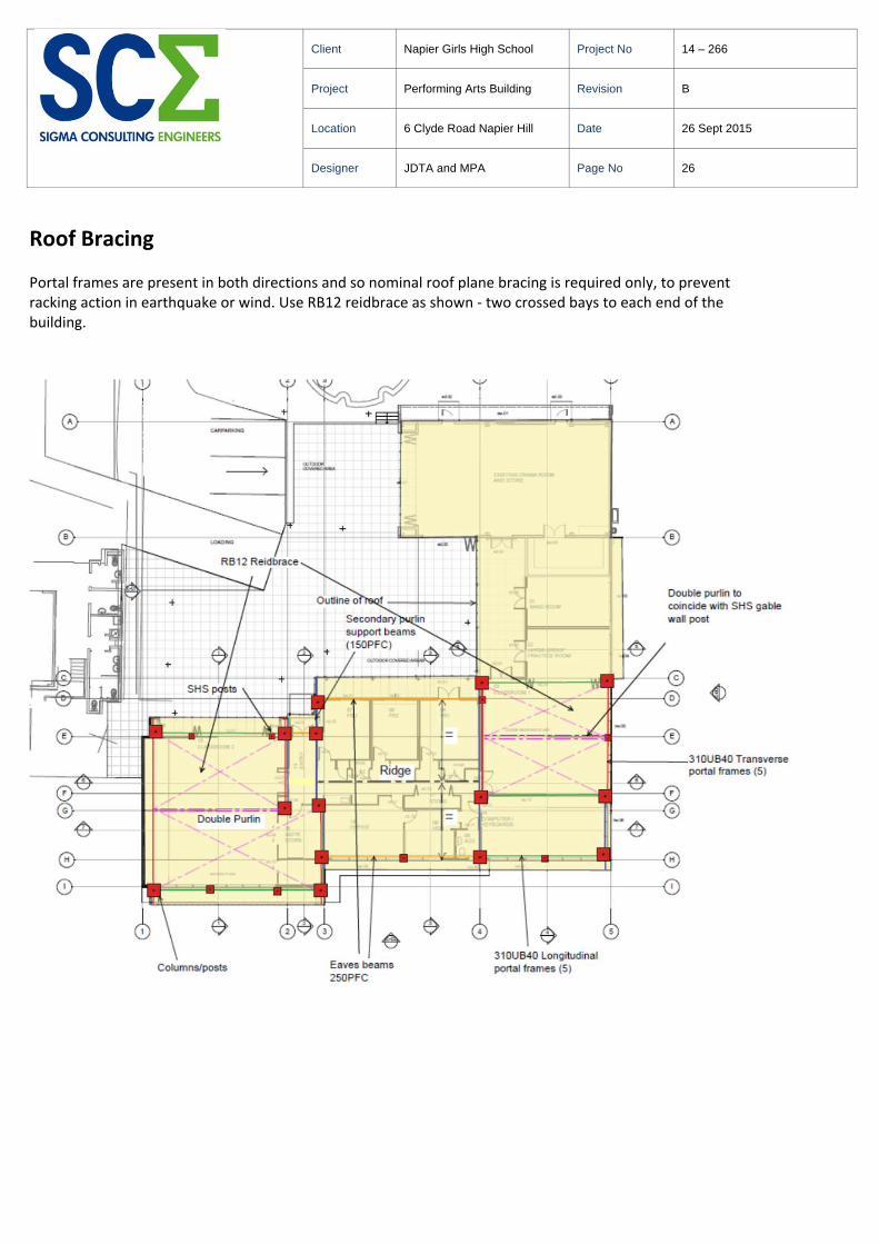
Roof Bracing Portal frames are present in both directions and so nominal roof plane bracing is required only, to prevent racking action in earthquake or wind. Use RB12 reidbrace as shown ‐ two crossed bays to each end of the building.
Client Napier Girls High School Project No 14 – 266
Project Performing Arts Building Revision B
Location 6 Clyde Road Napier Hill Date 26 Sept 2015
Designer JDTA and MPA Page No 26

Retaining Wall to South Face Existing foundation wall is not designed to support lateral forces as a retaining wall, and so a new retaining wall is to be added in front of it, to provide lateral support to the building. The existing wall will be called upon to resist vertical forces only. The new wall will resist lateral forces from the backfill and seismic forces. There will be no surcharge loads from the building to the new wall, as the building is supported on the existing wall. The building floor level is approximately 1200mm maximum above the adjacent ground level. Design parameters were provided in the RDCL report. Survey information has been presented by Cardno. The wall height is 1.4 metres maximum about foundation level. Information is extracted from MBIE and Build it Right Canterbury supplementary guidance dated July 2014 “Guidance on the seismic design of retaining structures for residential sites in Greater Christchurch”. Case 3 is adopted – i.e. the retaining wall supports the building foundation. SESOC_SOILS software utilised for design. Have carried out short term and long term analyses. Seismic force included in short term analysis only. For seismic design: Z = 0.38 Ch(T) = 1.0 (Class A and B (rock) sites) Adopt IL 2 so R = 1.0 Atopo = 1.0 say N = 1.0 C(T) = 1.0*(0.38*1.0*1.0) = 0.38 C(T, Atopo) = 0.38 Wd = 0.5 Therefore kn = 0.2
Client Napier Girls High School Project No 14 – 266
Project Performing Arts Building Revision B
Location 6 Clyde Road Napier Hill Date 26 Sept 2015
Designer JDTA and MPA Page No 27

Portal Column Foundations Critical Cases: G+Q: H = 17 kN and V = 55 kN G+W: H = 12 kN and V = 21 KN G+E: H = 20 kN and V = 38 KN Use SESOC_SOILS Software. Adopt parameters for shallow soils provided by RDCL – 75 kPa allowable bearing All cases work for a 900mm x 900mm x 400mm concrete foundation pad
15mm baseplate and M16 hold down bolts typically
Client Napier Girls High School Project No 14 – 266
Project Performing Arts Building Revision B
Location 6 Clyde Road Napier Hill Date 26 Sept 2015
Designer JDTA and MPA Page No 28

Foundations to Columns at Grids E1, E2, I1, I2, H4, H5, G2, G3, C4, F4 New 900x900x400 RC pads with columns centrally located 6‐HD16‐150 each way top and bottom and 75mm cover Existing concrete slab and footing broken out as required and existing rebar tied to existing footing rebar M16 hold‐down bolts to be cast into concrete foundation and baseplate fixed to these Pads at G2, G3F4 to be reviewed at time of concrete slab removal to confirm that hardfill beneath the slab is acceptable
Foundations to Columns at Grids C5, F5 Columns are located on edge of existing concrete slab/foundation wall Existing concrete needs to be removed and new foundations poured At F5 this will involve a reasonable amount of disruption as the slab is approx 1200mm above ground level – so the underlying hardfill will lose support. Over excavation is likely with replacement of hardfill.
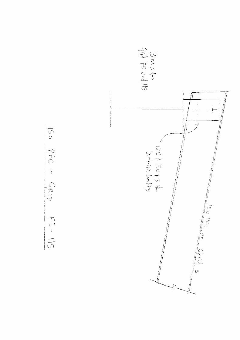
Base Fixing to 125x125x5.0 SHS Posts Plates to be on edge of existing slab so hold down bolts will be 62.5 mm from edge Weld SHS posts to 250x125x10 baseplates Drill two 14mm dia holes on longitudinal centreline with 30mm end distance Secure 125SHS posts to concrete slab with 250x115x10 plate and 2‐M12 Grade 5.8 anchor studs set in to 14mm diameter x 100mm length hole with Epcon C6.
Client Napier Girls High School Project No 14 – 266
Project Performing Arts Building Revision B
Location 6 Clyde Road Napier Hill Date 26 Sept 2015
Designer JDTA and MPA Page No 29

Plan
Client Napier Girls High School Project No 14 – 266
Project Performing Arts Building Revision B
Location 6 Clyde Road Napier Hill Date 26 Sept 2015
Designer JDTA and MPA Page No 30

Durability Statement
A Producer Statement – Design has been provided for this project, covering clause B1 of the Building Code – Structure. B2 – Durability has not been included as part of the Producer Statement – Design because there is no effective verification method for B2 contained within the Building Code.
The structural elements included in my documentation should however comply with the following:
Timber treatment should be selected in accordance with Table 1A of B2/AS1, which is utilised in NZS
3604:2011.
Concrete covers should be selected in accordance with NZS 3101 Part 1 section 3. Typically 75mm cover
is required to all rebar within concrete that is poured in contact with the ground.
The structural steel that is to be enclosed can be considered to be “interior”. An Alkyd Primer such as
system ALK4 will provide 10‐25 years to first maintenance on the basis of a low atmospheric category.
Exterior steel such as that supporting the parapet walls is in a very high atmospheric category, and an
inorganic zinc silicate coating IZS2 would provide 10‐15 years to first maintenance. These
recommendations are based on AS/NZS 2312 “Guide to the Protection of Structural Steel against
Atmospheric Corrosion by the Use of Protective Coatings”.
Concrete masonry should comply with NZS 4210:2001.
Client Napier Girls High School Project No 14 – 266
Project Performing Arts Building Revision B
Location 6 Clyde Road Napier Hill Date 26 Sept 2015
Designer JDTA and MPA Page No 31

Appendices SpaceGass12 Output for Portal Frames Sketches
Client Napier Girls High School Project No 14 – 266
Project Performing Arts Building Revision B
Location 6 Clyde Road Napier Hill Date 26 Sept 2015
Designer JDTA and MPA Page No 32


October 2006
Purlin Installation Guide
2.3.15 DHS COMPONENTS
2.3.15.1 FASTBRACE
Product DescriptionFastbrace is a lock-in bracing system which uses cleats with specially shaped lock-in tabs attached to each end of a 89 x 12 bracing channel, for use with DHS purlins up to and including DHS 300 series.
Pairs of Fastbrace are fi tted from each side of the DHS purlin through prepunched 18mm diameter round bracing holes and are locked together, minimising erection time.
When a line of Fastbrace has been installed, the system provides resistance to restrict lateral movement of the DHS purlin and also supports the purlin fl ange.
Limitations for UseThe end brace at the fi rst and last bracing points is secured using the standard bolted connection on the outermost cleat end.
To ensure straight alignment of the bracing system, the bracing holes can be offset by 25mm over the last purlin spacing to accommodate a bolted cleat. If this is not achieved, an angle of less than 2 degrees from a straight alignment is created, which in most cases is negligible and acceptable.
At the ridge, the lower bolt position is used to tie the bracing lines each side together using a sag rod.
Where back to back DHS purlins are used, bolted end brace components are required each side.
The durability of zinc coated products is dependent on the environment it will be used in, the grade of the zinc coating and the amount of maintenance that will be carried out over the life of the product. Refer Section 2.1.3 Environments for further guidelines.
MaintenanceMust be carried out in accordance with Section 2.1.6 Maintenance.
Handling and StorageThe Fastbrace system is delivered to site, usually strapped together, marked in bundles for installing in the same area of the roof structure. Refer to Section 2.6.2 Handling and Storage.
Material Specifi cation Base metal Steel Yield Standard thickness (BMT) grade strength zinc weight (mm) fy (MPa) Z (g/m2)
Bracing channel 1.15 G250 250 275End cleats 2.00 G250 250 275
Tolerances: Length ± 2mm Depth ± 1mm Width ± 1mm Web/fl ange angle 89 to 93 degrees

October 2006
Purlin Installation Guide
General Arrangement of the Fastbrace System
Standard Brace This is the standard Fastbrace component used almost everywhere in the system. It locksinto other standard brace components, adjustable brace components, or end brace components.
Adjustable BraceThis is the adjustable component in the Fastbrace system and is used where some level of adjustment on the purlin line is required. The purlin is adjusted into line and the 12mm diameter hex fl ange bolts on the brace tightened. The adjustable brace offers up to 20mm of adjustment.
End BraceEnd brace is used at the end of a purlin bracing line, i.e. eaves or ridge, each side of a roof step, or at top and bottom girts on a wall. The end brace locks into either standard or adjustable brace at one end and is twisted between the purlin lips and bolted into position at the other end.
Adjustable End BraceWhere the end purlin spacing is less than800mm, an adjustable end brace with a bolted end cleat is available, as twisting of the end cleat is not practical.The adjustable cleat can be rotated up to 15 degrees from normal, to accommodate the change in angle from vertical portal to the roof slope of the rafter.
2.3.15.1 FASTBRACE continued

May 2004
Purlin Installation Guide
2.3.15.2 BOLTED CHANNEL BRACING
Product DescriptionThe Dimond bolted channel bracing system uses cleats, clinched at each end of a 89 x 12 bracing channel, which are fastened through the DHS purlin with two bolts each end. Bolted channel bracing is used with the full DHS purlin range (DHS 150 to DHS 400 series).
This system uses bolted channel bracing between all purlins in the bracing line. Refer Section 2.3.9.1 for design basis.
At the ridge, the lower hole position is used to tie the bracing lines each side together using a sag rod.
Limitations for UseThe durability of zinc coated products is dependent on the environment it will be used in, the grade of the zinc coating and the amount of maintenance that will be carried out over the life of the product. Refer Section 2.1.3 Environments for further guidelines.
MaintenanceMust be carried out in accordance with Section 2.1.6 Maintenance.
Handling and StorageThe channel bracing system is delivered to site, usually strapped together, marked in bundles for installing in the same area of the roof structure. Refer to Section 2.6.2 Handling and Storage.
For the material specifi cations of the bracing refer to Section 2.3.15.1.
Components
Bolted Channel BraceThis is the standard component used in the bolted channel bracing system and is used almost everywhere.
Adjustable Bolted Channel BraceThis is the adjustable component in the bolted channel bracing system and is used where some level of adjustment on the purlin line is required. The purlin is adjusted into line and the 12mm diameter hex fl ange bolts on the brace tightened. The adjustable brace offers up to 20mm of adjustment.

August 2007
Purlin Installation Guide
2.3.15.3 PORTAL CLEATS
These are typically supplied by the fabricator or installer and welded on to the portal frame. Cleat thicknesses range from 6mm to 12mm thickness. The hole centres are laid out to suit hole punchings in the DHS purlin, refer to Section 2.3.16.3 Hole Locations for details. The cleat height may need to be increased where an expansion step in the roof is detailed.
2.3.15.4 SAG RODS
Alternating sag rods and channel have been superseded by the use of Fastbrace and the bolted channel bracing as the preferred bracing method. However the rods are still used as a cranked sag rod at the ridge to join each side together. Usually supplied by the steel erectors and fabricators in 12mm diameter engineering round bar grade 250 MPa, galvanised or electroplated fi nishes, with double nuts and washers each end. Where loads require, 16mm diameter engineering round bar can be used.
2.3.15.5 TIMBER STRIP
Timber strip battens are fi tted once the netting is in place to avoid roof insulation squashing down, over the purlin, as the roofi ng is screwed down.
Usually supplied and fi xed on site by the fabricator. However Dimond recommend using an ex 50mm x 50mm timber batten or a depth of batten equal to the thickness of the insulation gauged two sides and treated to H3 timber preservation such as boric or LOSP (low, organic solvent preservative). The CCA treatment process should be avoided, due to chemical contact with galvanised surface.
The batten is fi xed onto the top fl ange of the DHS Purlins, once the netting or safety mesh has been laid on the structure. Fixings to be 10g – 16 x 75mm. Countersunk rib head – wingtek. The coating fi nish is a zinc plated AS 3566 class 2 fi nish. Longer, other types of fi xings may need to be considered when the timber depth is greater than 65mm.
Spacing of the wingteks is dependent on the DHS material thickness it is being fi xed into. Refer to the following table.
DHS Purlin BMT Max. screw (mm) centres (mm)
1.15 250 1.25 to 2.0 300
At these centres, the maximum outward load on the nailing strip is 5.0 kN/m.

August 2007
Purlin Installation Guide
Continued on next page
2.3.16 DHS CAD DETAILS
DHS CAD details are shown in this section. For the latest DHS CAD details, please download from the Dimond website www.dimond.co.nz. Follow the steps below:
1. Log in to the Architects/Specifi ers section.2. Click on the green “Structural Systems Manual” button.3. Click on the “Download CAD details” button.4. Select from product list shown to view CAD details available for that product.
Please note all of these details are to be used as a guide only and are not intended for construction. Specifi c design details are required to be provided by the design engineer.
2.3.16.1 DHS PROFILES
Not to scale.

August 2007
Purlin Installation Guide
Continued on next page
2.3.16 DHS CAD DETAILS continued
2.3.16.2 RECOMMENDED DIMENSIONS OF PORTAL CLEATS FOR USE WITH DHS PURLINS & GIRTS
Not to scale.

New Slabs


Plan
Column Detail at Grid H5 (H4 and F5 similar)

New Slabs
