caepipe version 5 - · pdf filepower piping asme b31.1 (2016) allowable pressure at this time,...
TRANSCRIPT

Readme Supplement
Version 7.70
Disclaimer
Please read the following carefully:
This software and this document have been developed and checked for correctness and accuracy by SST Systems, Inc. (SST) and InfoPlant Technologies Pvt. Ltd. (InfoPlant). However, no warranty, expressed or implied, is made by SST and InfoPlant as to the accuracy and correctness of this document or the functioning of the software and the accuracy, correctness and utilization of its calculations.
Users must carry out all necessary tests to assure the proper functioning of the software and the applicability of its results. All information presented by the software is for review, interpretation, approval and application by a Registered Professional Engineer.
CAEPIPE is a trademark of SST and InfoPlant.
CAEPIPE Version 7.70, © 2016, SST Systems, Inc. and InfoPlant Technologies Pvt. Ltd.
All Rights Reserved.
SST Systems, Inc. Tel: (408) 452-8111
1798 Technology Drive, Suite 236 Fax: (408) 452-8388
San Jose, California 95110 Email: [email protected]
USA www.sstusa.com
InfoPlant Technologies Pvt. Ltd. Tel: +91-80-40336999
7, Crescent Road Fax: +91-80-41494967
Bangalore 560001 Email: [email protected]
India
TM

Annexure A
Code Compliance

Power Piping ASME B31.1 (2016)
Allowable Pressure
At this time, there is no provision in CAEPIPE to specify the type of pipe construction, i.e., whether the pipe is a seamless or longitudinal welded or spiral welded. Accordingly, irrespective of the type of pipe construction, CAEPIPE calculates allowable pressure as follows.
For straight pipes and bends with seamless construction or designed for sustained operation below the creep range, Eq. (9) of para.104.1.2 is used as given below to compute allowable pressure.
ao
a
aYtD
SEtP
2
2
For straight pipes and bends designed for sustained operation within the creep range, Eq. (11) of para.104.1.4 is used as given below to calculate allowable pressure.
ao
a
aYtD
SEWtP
2
2
where
Pa = allowable pressure
SE = allowable stress as given in Appendix A of B31.1 (2016) Code, where
E = weld joint efficiency factor or casting quality factor as given in Table 102.4.3
ta = available thickness for pressure design = tn × (1 - mill tolerance/100) - corrosion allowance
(Any additional thickness required for threading, grooving, erosion, corrosion, etc., should be included in corrosion allowance in CAEPIPE)
tn = nominal pipe thickness
Do = outside diameter of pipe
d = inside diameter of pipe
The Pressure coefficient Y is implemented as per Table 104.1.2 (A). In addition,
Y = 0.0, for cast iron
oDd
dY
, if Do/ta < 6, for ferritic and austenitic steels designed for temperatures of 900
oF
(480oC) and below
W = weld strength reduction factor as per Table 102.4.7. Refer to Annexure B for details on Weld strength reduction factor implemented in CAEPIPE.
For closely spaced miter bends, the allowable pressure is calculated from Eq. (C.3.1) of para.104.3.3.
)2/(
)(
rRr
rRSEtP a
a
where
r = mean radius of pipe = (Do - tn)/2
R = equivalent bend radius of the miter

Power Piping ASME B31.1 (2016)
For widely spaced miter bends, the allowable pressure is calculated from Eq. (C.3.2) of para. 104.3.3.
)tan25.1(
2
aa
a
arttr
SEtP
Where, = miter half angle
Sustained Stress
The stress (SL) due to sustained loads (pressure, weight and other sustained mechanical loads) is calculated from Eq. 15 of para.104.8.1
hA
n
o
L SZ
iM
t
PDS
75.0
4
where
P = maximum of CAEPIPE pressures P1 through P10
Do = outside diameter
tn = nominal wall thickness
i = stress intensification factor. The product 0.75i shall not be less than 1.0.
MA = resultant bending moment due to weight and other sustained loads
Z = uncorroded section modulus; for reduced outlets, effective section modulus as per para. 104.8.4
Sh = hot allowable stress at maximum CAEPIPE temperature [i.e., at max (Tref, T1 through T10)]
Occasional Stress
The stress (SLo) due to occasional loads is calculated from Eq. 16 of para.104.8.2 as the sum of stress due to sustained loads (SL) and stress due to occasional loads (So) such as earthquake or wind. Wind and earthquake are not considered concurrently.
hBA
n
opeak
Lo SZ
iM
Z
iM
t
DPS 2.1
75.075.0
4
where
MB = resultant bending moment on the cross-section due to occasional loads such as thrusts from relief / safety valve loads, from pressure and flow transients, earthquake, wind etc.
Ppeak = peak pressure = (peak pressure factor in CAEPIPE) x P, where P is defined above
Expansion Stress Range (i.e., Stress due to Displacement Load Range)
The stress (SE) due to thermal expansion is calculated from Eq. 17 of para.104.8.3.
A
C
E SZ
iMS
where
MC = resultant moment due to thermal expansion
)25.025.1( hCA SSfS , from Eq. (1A) of para. 102.3.2 (B)
f cyclic stress range reduction factor from Eq.(1C) of para. 102.3.2(B),
f 6/N0.2
<= 1.0 and f >= 0.15 with N being the total number of equivalent reference displacement
stress range cycles expected during the service life of the piping
SC = basic allowable stress at minimum metal temperature expected during the displacement cycle under analysis

Power Piping ASME B31.1 (2016)
Sh = basic allowable stress at maximum metal temperature expected during the displacement cycle under analysis
When Sh is greater than SL, the allowable stress range may be calculated as
])(25.1[ LhCA SSSfS , from Eq. (1B) of para. 102.3.2 (B)
This is specified as an analysis option: “Use liberal allowable stresses”, in the menu Options->Analysis on the Code tab of CAEPIPE.
Note:
Refer Annexure C for the details of “Thickness” and the “Section Modulus” used by CAEPIPE for weight, pressure and stress calculations.

Power Piping ASME B31.1 (2016)

Power Piping ASME B31.1 (2016)

Power Piping ASME B31.1 (2016)

Power Piping ASME B31.1 (2016)

Power Piping ASME B31.1 (2016)
Refrigeration Piping and Heat Transfer Components
ASME B31.5 (2016)
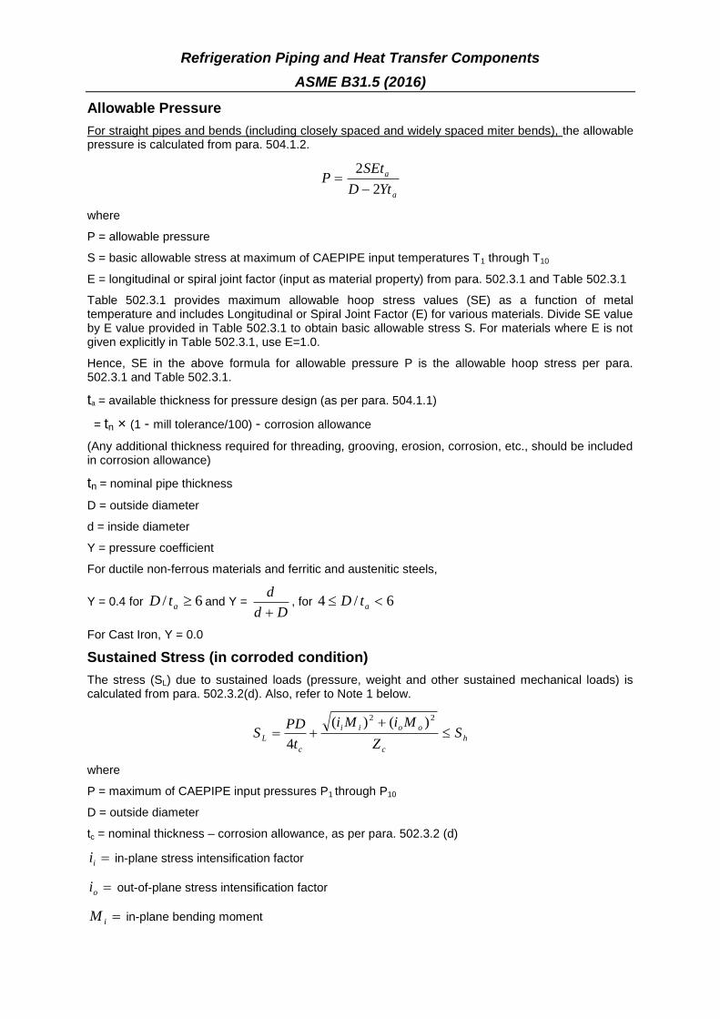
Allowable Pressure
For straight pipes and bends (including closely spaced and widely spaced miter bends), the allowable pressure is calculated from para. 504.1.2.
a
a
YtD
SEtP
2
2
where
P = allowable pressure
S = basic allowable stress at maximum of CAEPIPE input temperatures T1 through T10
E = longitudinal or spiral joint factor (input as material property) from para. 502.3.1 and Table 502.3.1
Table 502.3.1 provides maximum allowable hoop stress values (SE) as a function of metal temperature and includes Longitudinal or Spiral Joint Factor (E) for various materials. Divide SE value by E value provided in Table 502.3.1 to obtain basic allowable stress S. For materials where E is not given explicitly in Table 502.3.1, use E=1.0.
Hence, SE in the above formula for allowable pressure P is the allowable hoop stress per para. 502.3.1 and Table 502.3.1.
ta = available thickness for pressure design (as per para. 504.1.1)
= tn × (1 - mill tolerance/100) - corrosion allowance
(Any additional thickness required for threading, grooving, erosion, corrosion, etc., should be included in corrosion allowance)
tn = nominal pipe thickness
D = outside diameter
d = inside diameter
Y = pressure coefficient
For ductile non-ferrous materials and ferritic and austenitic steels,
Y = 0.4 for 6/ atD and Y = Dd
d
, for 6/4 atD
For Cast Iron, Y = 0.0
Sustained Stress (in corroded condition)
The stress (SL) due to sustained loads (pressure, weight and other sustained mechanical loads) is calculated from para. 502.3.2(d). Also, refer to Note 1 below.
h
c
ooii
c
L SZ
MiMi
t
PDS
22 )()(
4
where
P = maximum of CAEPIPE input pressures P1 through P10
D = outside diameter
tc = nominal thickness – corrosion allowance, as per para. 502.3.2 (d)
ii in-plane stress intensification factor
oi out-of-plane stress intensification factor
iM in-plane bending moment

Refrigeration Piping and Heat Transfer Components
ASME B31.5 (2016)
oM out-of-plane bending moment
Zc = corroded section modulus as per para. 502.3.2 (d)
Sh = basic allowable stress at maximum of CAEPIPE input temperatures T1 through T10
Occasional Stress (in corroded condition)
The stress (SLo) due to occasional loads is calculated as the sum of stress due to sustained loads (SL) and stress due to occasional loads (So) such as earthquake or wind. Wind and earthquake are not considered concurrently (see para. 502.3.3 (a)). Also, refer to Note 1 below.
h
occasionalc
ooii
sustainedc
ooii
c
peak
Lo SZ
MiMi
Z
MiMi
t
DPS 33.1
)()()()(
4
2222
where
Ppeak = peak pressure = (peak pressure factor in CAEPIPE) x P, where P is defined above
Expansion Stress (in uncorroded condition)
The stress (SE) due to thermal expansion is calculated from para. 519.4.5 and para. 519.3.5. Also see Note 2 below.
AtbE SSSS 22 4
where
bS resultant bending stress = Z
MiMi ooii
22 )()(
tS torsional stress = Z
M t
2
Mt = torsional moment
Z = uncorroded section modulus; for reduced outlets, effective section modulus
)25.025.1( hotColdA SSfS (see para. 502.3.2 (c))
f stress range reduction factor from Figure 502.3.2
SCold = basic allowable stress at minimum metal temperature expected during the displacement cycle under analysis
Shot = basic allowable stress at maximum metal temperature expected during the displacement cycle under analysis
When Sh is greater than SL, the allowable stress range may be calculated as
LhAA SSfSS
where, Sh = basic allowable stress at maximum of CAEPIPE input temperatures T1, through T10
This is specified as an analysis option: “Use liberal allowable stresses”, in the CAEPIPE menu Options->Analysis on the Code tab.
Notes:
1. As per para. 502.3.2 (d), the pressure stress should be calculated using the formula Pd2/(D
2-
d2), where d is the internal diameter = D-2tc. This can be selected through Options >
Analysis > Pressure
2. As per para. 519.4.5(a), Bending and torsional stress shall be computed using the as-installed modulus of elasticity, i.e., Ec at installation temperature. Hence, "Use modulus at reference

Refrigeration Piping and Heat Transfer Components
ASME B31.5 (2016)
temperature" (available through CAEPIPE Layout > Options > Analysis > Temperature) is set as "default" and is disabled for user to modify.
3. Refer Annexure C for the details of “Thickness” and the “Section Modulus” used by CAEPIPE for weight, pressure and stress calculations.

Refrigeration Piping and Heat Transfer Components
ASME B31.5 (2016)
Refrigeration Piping and Heat Transfer Components
ASME B31.5 (2016)

Building Services Piping
ASME B31.9 (2014)
Allowable Pressure
For straight pipes and bends, the calculation of allowable pressure is based on Eq. 2 of paras.904.1.1 and 904.2.1.
D
AtSEP m )(2
where
P = allowable pressure
SE = allowable hoop stress, given in Appendix I of B31.9 (2014) Code, where
E = longitudinal or spiral weld joint efficiency factor or casting quality factor
tm = minimum required pipe thickness as per para.904.1.1(a)
= tn × (1 - mill tolerance/100)
tn = nominal pipe thickness
A = corrosion allowance
(Any additional thickness required for threading, grooving, erosion, corrosion, etc., should be included in “corrosion allowance” in CAEPIPE)
D = outside diameter
For closely and widely spaced miter bends, the allowable pressure shall be the lower positive value calculated from Eqs. (3A) and (3B) of para 904.2.2 (a)
rTT
T
r
SETP
tan64.0 Eq. (3A)
2/rR
rR
r
SETP Eq. (3B)
where
r = mean radius of pipe = (D - tn) / 2
T = tm – A, where tm and A are defined above
R = effective bend radius of the miter
= miter half angle
Sustained Stress (in uncorroded condition)
The longitudinal stress (SL) due to sustained loads (pressure, weight and other sustained mechanical loads) is calculated as mentioned in para.902.3.2 (d)
hA
n
o
L SZ
iM
t
PDS
75.0
4
where
P = maximum of CAEPIPE pressures P1 through P10
Do = outside diameter
tn = nominal wall thickness
i = stress intensification factor. The product 0.75i shall not be less than 1.0.
MA = resultant bending moment due to weight and other sustained loads
Z = uncorroded section modulus; for reduced outlets, effective section modulus

Building Services Piping
ASME B31.9 (2014)
Sh = hot allowable stress at maximum CAEPIPE temperatures [i.e., at max (Tref, T1 through T10)]
Occasional Stress (in uncorroded condition)
The longitudinal stress (SLo) due to occasional loads is calculated as mentioned in para.902.3.3 (a) as the sum of stresses due to pressure, live and dead loads and stress due to occasional loads (So) such as earthquake or wind. Wind and earthquake are not considered to occur concurrently.
hBA
n
opeak
Lo SZ
iM
Z
iM
t
DPS 33.1
75.075.0
4
where
MB = resultant bending moment due to occasional loads
Ppeak = peak pressure = (peak pressure factor) x P
Expansion Stress (in uncorroded condition)
The stress (SE) due to thermal expansion is calculated from para.902.3.2 (c), para.919.2.1 and para.919.4.1 (b).
A
C
E SZ
iMS
where
MC = resultant moment due to thermal expansion
)25.025.1( hCA SSfS
f = stress range reduction factor = 6/N0.2, where N being the total number of equivalent reference
displacement stress range cycles expected during the service life of the piping. Also 0.15 f 1.0
SC = basic allowable stress as minimum metal temperature expected during the displacement cycle under analysis [i.e., at min (Tref, T1 through T10)
Sh = basic allowable stress as maximum metal temperature expected during the displacement cycle under analysis [i.e., at max (Tref, T1 through T10)
When Sh is greater than SL, the allowable stress range SA may be calculated as per para. 902.3.2 (d).
])(25.1[ LhCA SSSfS
This is specified as an analysis option: “Use liberal allowable stresses”, in the CAEPIPE menu Options->Analysis on the “Code” tab.
Oil and gas pipeline systems Z662 (2015)
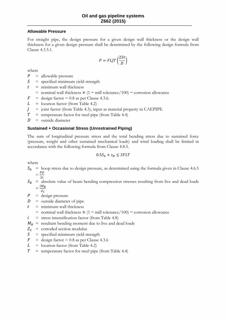
Allowable Pressure
For straight pipe, the design pressure for a given design wall thickness or the design wall thickness for a given design pressure shall be determined by the following design formula from Clause 4.3.5.1.
𝑃 = 𝐹𝐿𝐽𝑇 (2𝑆𝑡
𝐷)
where
𝑃 = allowable pressure
𝑆 = specified minimum yield strength
𝑡 = minimum wall thickness
= nominal wall thickness × (1 − mill tolerance/100) − corrosion allowance
𝐹 = design factor = 0.8 as per Clause 4.3.6.
𝐿 = location factor (from Table 4.2)
𝐽 = joint factor (from Table 4.3), input as material property in CAEPIPE
𝑇 = temperature factor for steel pipe (from Table 4.4)
𝐷 = outside diameter
Sustained + Occasional Stress (Unrestrained Piping)
The sum of longitudinal pressure stress and the total bending stress due to sustained force (pressure, weight and other sustained mechanical loads) and wind loading shall be limited in accordance with the following formula from Clause 4.8.5.
0.5𝑆ℎ + 𝑠𝐵 ≤ 𝑆𝐹𝐿𝑇
where
𝑆ℎ = hoop stress due to design pressure, as determined using the formula given in Clause 4.6.5
= 𝑃𝐷
2𝑡
𝑆𝐵 = absolute value of beam bending compression stresses resulting from live and dead loads
= 𝑖𝑀𝐵
𝑍𝐶
𝑃 = design pressure
𝐷 = outside diameter of pipe
𝑡 = minimum wall thickness
= nominal wall thickness × (1 − mill tolerance/100) − corrosion allowance
𝑖 = stress intensification factor (from Table 4.8)
𝑀𝐵 = resultant bending moment due to live and dead loads
𝑍𝐶 = corroded section modulus
𝑆 = specified minimum yield strength
𝐹 = design factor = 0.8 as per Clause 4.3.6
𝐿 = location factor (from Table 4.2)
𝑇 = temperature factor for steel pipe (from Table 4.4)

Oil and gas pipeline systems Z662 (2015)
Expansion Stress (Unrestrained Piping)
The thermal expansion stress range (𝑆𝐸) for those portions of pipeline systems without axial restraint shall be combined in accordance with the formulae given in Clause 4.8.3 and 4.8.4.
𝑆𝐸 = √𝑆𝑏2 + 4𝑆𝑡
2 ≤ 0.72𝑆𝑇
where
𝑆𝑏 = resultant bending stress= 𝑖𝑀𝑏/Z
𝑆𝑡 = torsional stress = 𝑀𝑡/(2Z) 𝑀𝑏 = resultant bending moment due to expansion loads
𝑀𝑡 = torsional moment due to expansion loads
𝑍 = un-corroded section modulus
𝑖 = stress intensification factor (from Table 4.8)
𝑆 = specified minimum yield strength
𝑇 = temperature factor for steel pipe (from Table 4.4)
Combined Stress (Restrained Piping)
For those portions of restrained pipelines, the combined stress shall be limited in accordance with the formula given in Clause 4.7.2.1.
𝑆ℎ − 𝑆𝐿 + 𝑠𝐵 ≤ 𝑆𝑇
where
𝑆ℎ = hoop stress due to design pressure, as determined using the formula given in Clause 4.6.5
= 𝑃𝐷
2𝑡
𝑆𝐿 = longitudinal compressive stress as determined using the formula given in Clause 4.7.1
=𝑆𝐿 = 𝜗𝑆ℎ − 𝐸𝑐𝛼(𝑇𝑜𝑝𝑟 − 𝑇𝑟𝑒𝑓)
𝑆𝐵 = absolute value of beam bending compression stresses resulting from live and dead loads
= 𝑖𝑀𝐵
𝑍𝐶
𝑃 = design pressure
𝐷 = outside diameter of pipe
𝑡 = minimum wall thickness
= nominal wall thickness × (1 − mill tolerance/100) − corrosion allowance
𝑖 = stress intensification factor (from Table 4.8)
𝑀𝐵 = resultant bending moment due to live and dead loads
𝑍𝐶 = corroded section modulus
𝜗 = Poisson’s ratio
𝐸𝑐 = modulus of elasticity of steel at 𝑇𝑟𝑒𝑓
𝑇𝑜𝑝𝑟 = operating temperature under consideration (T1, T2, T3, … T10 in CAEPIPE)
𝑇𝑟𝑒𝑓 = ambient temperature at the time of restraint = Reference temperature in CAEPIPE
𝛼 = coefficient of thermal expansion at 𝑇𝑜𝑝𝑟 defined above
𝑆 = specified minimum yield strength
𝑇 = temperature factor for steel pipe (from Table 4.4)
Note:
Evaluation as per Clause 4.7.2.1 (listed above) for Restrained Piping shall be performed in CAEPIPE only when the value of SL computed as listed above is negative (compressive).

Oil and gas pipeline systems Z662 (2015)

Oil and gas pipeline systems Z662 (2015)

Annexure B
Weld Strength Reduction Factors built into CAEPIPE
(as given in Table 102.4.7 of ASME B31.1 – 2016)
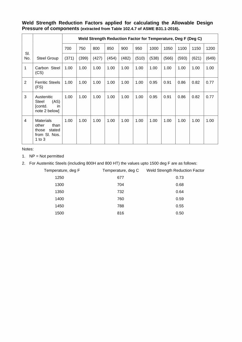
Weld Strength Reduction Factors applied for calculating the Allowable Design Pressure of components (extracted from Table 102.4.7 of ASME B31.1-2016).
Sl. No. Steel Group
Weld Strength Reduction Factor for Temperature, Deg F (Deg C)
700 750 800 850 900 950 1000 1050 1100 1150 1200
(371) (399) (427) (454) (482) (510) (538) (566) (593) (621) (649)
1 Carbon Steel (CS)
1.00 1.00 1.00 1.00 1.00 1.00 1.00 1.00 1.00 1.00 1.00
2 Ferritic Steels (FS)
1.00 1.00 1.00 1.00 1.00 1.00 0.95 0.91 0.86 0.82 0.77
3 Austenitic Steel (AS) [contd. in note 2 below]
1.00 1.00 1.00 1.00 1.00 1.00 0.95 0.91 0.86 0.82 0.77
4 Materials other than those stated from Sl. Nos. 1 to 3
1.00 1.00 1.00 1.00 1.00 1.00 1.00 1.00 1.00 1.00 1.00
Notes:
1. NP = Not permitted
2. For Austenitic Steels (including 800H and 800 HT) the values upto 1500 deg F are as follows:
Temperature, deg F Temperature, deg C Weld Strength Reduction Factor
1250 677 0.73
1300 704 0.68
1350 732 0.64
1400 760 0.59
1450 788 0.55
1500 816 0.50

Annexure C
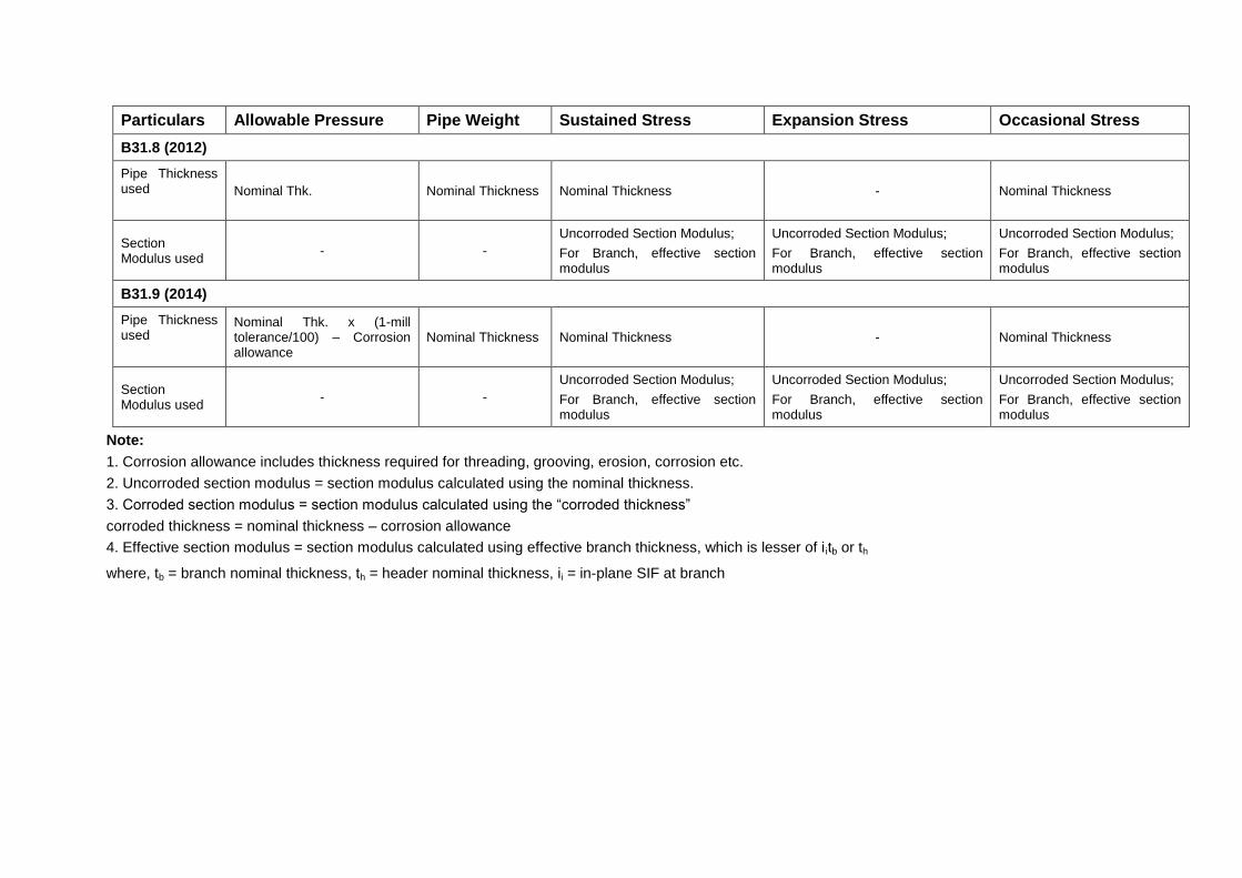
Thickness and Section Modulus used by CAEPIPE in Weight, Pressure and Stress Calculations for ASME B31.x Codes

Particulars Allowable Pressure Pipe Weight Sustained Stress Expansion Stress Occasional Stress
B31.1 (2016)
Pipe Thickness used
Nominal Thk. x (1-mill tolerance/100) – Corrosion allowance
Nominal Thickness Nominal Thickness - Nominal Thickness
Section Modulus used
- -
Uncorroded Section Modulus;
For Branch, effective section modulus
Uncorroded Section Modulus;
For Branch, effective section modulus
Uncorroded Section Modulus;
For Branch, effective section modulus
B31.3 (2014)
Pipe Thickness used
Nominal Thk. x (1-mill tolerance/100) – Corrosion allowance
Nominal Thickness Nominal Thickness - Corrosion allowance
- Nominal Thickness – Corrosion allowance
Section Modulus used
- -
Corroded Section Modulus;
For Branch, effective section modulus
Uncorroded Section Modulus;
For Branch, effective section modulus
Corroded Section Modulus;
For Branch, effective section modulus
B31.4 (2012)
Pipe Thickness used
Nominal Thk. x (1-mill tolerance/100) – Corrosion allowance
Nominal Thickness Nominal Thickness - Nominal Thickness
Section Modulus used
- -
Uncorroded Section Modulus;
For Branch, effective section modulus
Uncorroded Section Modulus;
For Branch, effective section modulus
Uncorroded Section Modulus;
For Branch effective section modulus
B31.5 (2016)
Pipe Thickness used
Nominal Thk. x (1-mill tolerance/100) – Corrosion allowance
Nominal Thickness Nominal Thickness – Corrosion allowance
- Nominal Thickness – Corrosion allowance
Section Modulus used
- -
Corroded Section Modulus;
For Branch, effective section modulus
Uncorroded Section Modulus;
For Branch, effective section modulus
Corroded Section Modulus;
For Branch, effective section modulus
Particulars Allowable Pressure Pipe Weight Sustained Stress Expansion Stress Occasional Stress
B31.8 (2012)
Pipe Thickness used
Nominal Thk. Nominal Thickness Nominal Thickness - Nominal Thickness
Section Modulus used
- -
Uncorroded Section Modulus;
For Branch, effective section modulus
Uncorroded Section Modulus;
For Branch, effective section modulus
Uncorroded Section Modulus;
For Branch, effective section modulus
B31.9 (2014)
Pipe Thickness used
Nominal Thk. x (1-mill tolerance/100) – Corrosion allowance
Nominal Thickness Nominal Thickness - Nominal Thickness
Section Modulus used
- -
Uncorroded Section Modulus;
For Branch, effective section modulus
Uncorroded Section Modulus;
For Branch, effective section modulus
Uncorroded Section Modulus;
For Branch, effective section modulus
Note:
1. Corrosion allowance includes thickness required for threading, grooving, erosion, corrosion etc.
2. Uncorroded section modulus = section modulus calculated using the nominal thickness.
3. Corroded section modulus = section modulus calculated using the “corroded thickness”
corroded thickness = nominal thickness – corrosion allowance
4. Effective section modulus = section modulus calculated using effective branch thickness, which is lesser of i itb or th
where, tb = branch nominal thickness, th = header nominal thickness, ii = in-plane SIF at branch

Annexure D
ANSI/API Standard 610
Eleventh Edition, September 2010
ISO 13709: 2009, (Identical) Centrifugal pumps for petroleum, petrochemical and natural gas industries

API Standard 610, 11th
Edition, Sep 2010 / ISO 13709:2009
API 610 (11th Edition, 2010) / ISO 13709:2009 for Pumps
The allowable nozzle forces and moments for pumps are taken from Table 4 of the eleventh edition of API Standard 610 / ISO 13709.

API Standard 610, 11th
Edition, Sep 2010 / ISO 13709:2009

API Standard 610, 11th
Edition, Sep 2010 / ISO 13709:2009
The coordinate systems and nozzle orientations for various pump configurations are shown next.

API Standard 610, 11th
Edition, Sep 2010 / ISO 13709:2009

API Standard 610, 11th
Edition, Sep 2010 / ISO 13709:2009

API Standard 610, 11th
Edition, Sep 2010 / ISO 13709:2009
Criteria for Piping Design
The criteria for piping design are taken from Appendix F of the API 610.

API Standard 610, 11th
Edition, Sep 2010 / ISO 13709:2009

API Standard 610, 11th
Edition, Sep 2010 / ISO 13709:2009

Verification of API 610 Pump Compliance
Implementation of API 610 Pump Compliance in CAEPIPE is verified using the sample provided in API Standard 610, 11
th Edition and presented in this section.
CAEPIPE model corresponding to the above API Publication sample


Results from API 610, 11th Edition

Results from CAEPIPE Rotating Equipment Report

Annexure E
Response Spectrum Libraries

Response Spectrum Libraries
Fourteen (14) new Response Spectrum Libraries have been added as per the following.
1. EL Centro May 18, 1940
2. Uniform Building Code (UBC) 1991 Edition and
3. Nuclear Regulatory Commission (NRC) Guide 1.60
EL Centro
This spectrum data can be accessed by selecting the file “ELCentro_NS_May18_1940.spe” available in the folder “SpectrumLibrary” through Layout window > Misc > Spectrums > File > Library.
This predefined data is taken from “J’Bigs, Introduction to Structural Dynamics” and is based on the north-south component of the May 18, 1940 El Centro California earthquake. As stated in this document, the recorded maximum quantities were 0.33g, 13.7 in/sec, and 8.3 in. This is intended to apply to elastic systems having between 5 and 10 % critical damping. For the El Centro input given below, the three straight lines are defined by.
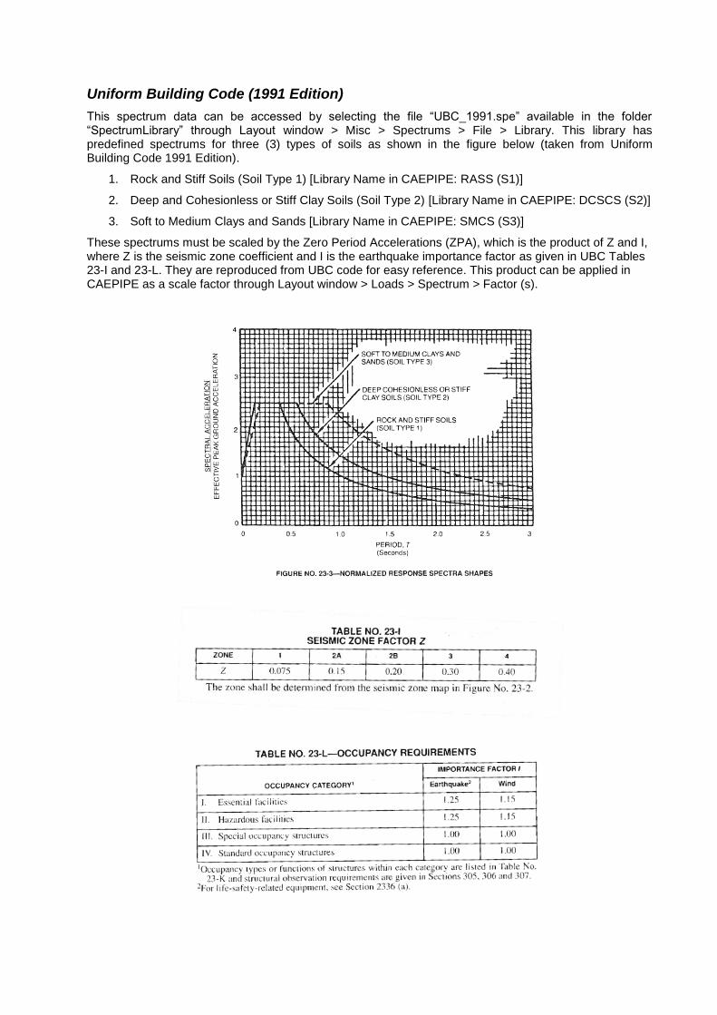
Uniform Building Code (1991 Edition)
This spectrum data can be accessed by selecting the file “UBC_1991.spe” available in the folder “SpectrumLibrary” through Layout window > Misc > Spectrums > File > Library. This library has predefined spectrums for three (3) types of soils as shown in the figure below (taken from Uniform Building Code 1991 Edition).
1. Rock and Stiff Soils (Soil Type 1) [Library Name in CAEPIPE: RASS (S1)]
2. Deep and Cohesionless or Stiff Clay Soils (Soil Type 2) [Library Name in CAEPIPE: DCSCS (S2)]
3. Soft to Medium Clays and Sands [Library Name in CAEPIPE: SMCS (S3)]
These spectrums must be scaled by the Zero Period Accelerations (ZPA), which is the product of Z and I, where Z is the seismic zone coefficient and I is the earthquake importance factor as given in UBC Tables 23-I and 23-L. They are reproduced from UBC code for easy reference. This product can be applied in CAEPIPE as a scale factor through Layout window > Loads > Spectrum > Factor (s).
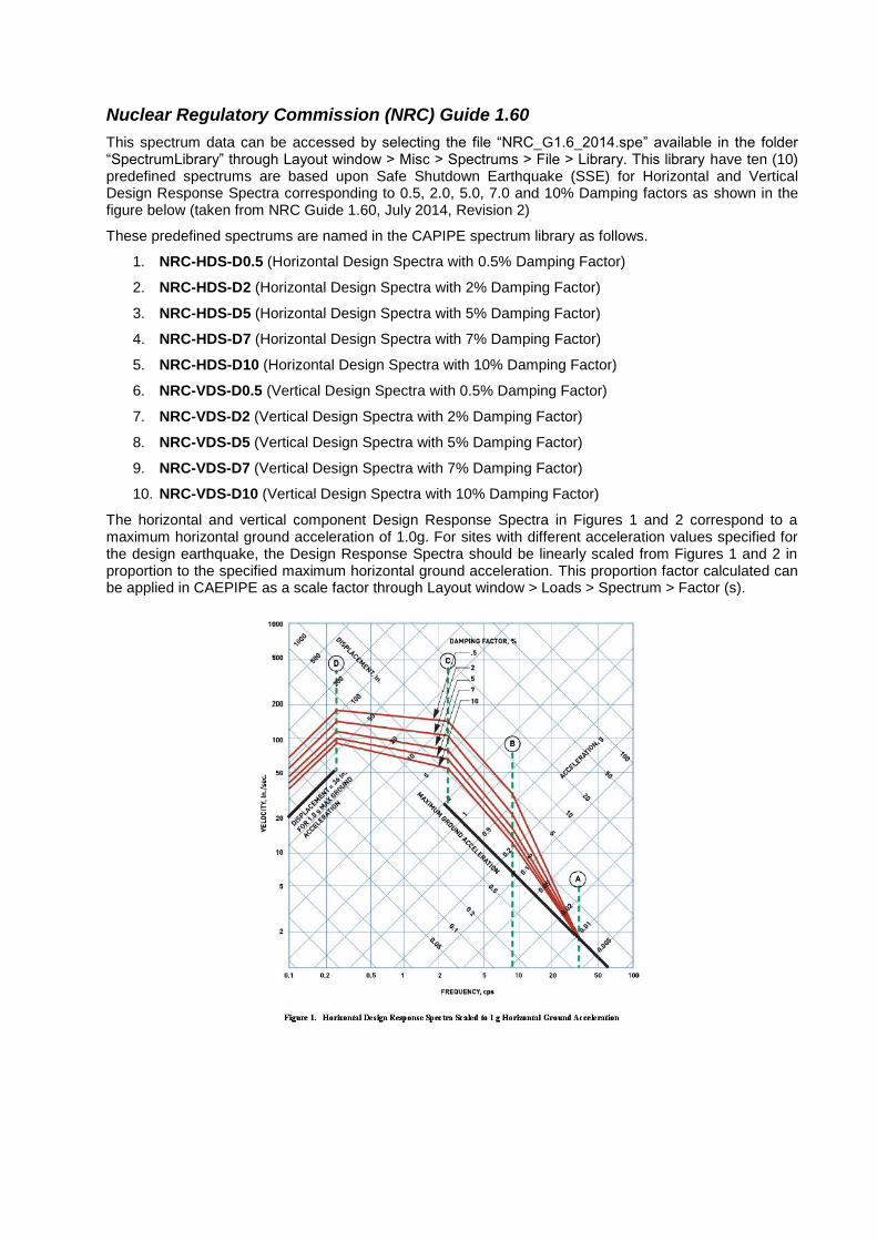
Nuclear Regulatory Commission (NRC) Guide 1.60
This spectrum data can be accessed by selecting the file “NRC_G1.6_2014.spe” available in the folder “SpectrumLibrary” through Layout window > Misc > Spectrums > File > Library. This library have ten (10) predefined spectrums are based upon Safe Shutdown Earthquake (SSE) for Horizontal and Vertical Design Response Spectra corresponding to 0.5, 2.0, 5.0, 7.0 and 10% Damping factors as shown in the figure below (taken from NRC Guide 1.60, July 2014, Revision 2)
These predefined spectrums are named in the CAPIPE spectrum library as follows.
1. NRC-HDS-D0.5 (Horizontal Design Spectra with 0.5% Damping Factor)
2. NRC-HDS-D2 (Horizontal Design Spectra with 2% Damping Factor)
3. NRC-HDS-D5 (Horizontal Design Spectra with 5% Damping Factor)
4. NRC-HDS-D7 (Horizontal Design Spectra with 7% Damping Factor)
5. NRC-HDS-D10 (Horizontal Design Spectra with 10% Damping Factor)
6. NRC-VDS-D0.5 (Vertical Design Spectra with 0.5% Damping Factor)
7. NRC-VDS-D2 (Vertical Design Spectra with 2% Damping Factor)
8. NRC-VDS-D5 (Vertical Design Spectra with 5% Damping Factor)
9. NRC-VDS-D7 (Vertical Design Spectra with 7% Damping Factor)
10. NRC-VDS-D10 (Vertical Design Spectra with 10% Damping Factor)
The horizontal and vertical component Design Response Spectra in Figures 1 and 2 correspond to a maximum horizontal ground acceleration of 1.0g. For sites with different acceleration values specified for the design earthquake, the Design Response Spectra should be linearly scaled from Figures 1 and 2 in proportion to the specified maximum horizontal ground acceleration. This proportion factor calculated can be applied in CAEPIPE as a scale factor through Layout window > Loads > Spectrum > Factor (s).

Horizontal Component:
The numerical values of design displacements, velocities, and accelerations for the horizontal component Design Response Spectra are obtained by multiplying the corresponding values of the maximum ground displacement and acceleration by the factors given in Table 1 given below. In Figure 1, the base diagram consists of three parts: the bottom line on the left part represents the maximum ground displacement, the bottom line on the right part represents the maximum acceleration, and the middle part depends on the maximum velocity. The horizontal component Design Response Spectra in Figure 1 of this guide correspond to a maximum horizontal ground acceleration of 1.0g. The maximum ground displacement is taken proportional to the maximum ground acceleration, and is set at 36 inches for a ground acceleration of 1.0 g. The displacement region lines of the Design Response Spectra are parallel to the maximum ground displacement line and are shown on the left of Figure 1. The velocity region lines slope downward from a frequency of 0.25 cycles per second (cps) or Hertz (Hz) (control point D) to a frequency of 2.5 cps (control point C) and are shown at the top. The remaining two sets of lines between the frequencies of 2.5 cps and 33 cps (control point A), with a break at a frequency of 9 cps (control point B), constitute the acceleration region of the horizontal Design Response Spectra. For frequencies higher than 33 cps, the maximum ground acceleration line represents the Design Response Spectra.
a. Maximum ground displacement is taken proportional to maximum ground acceleration, and is 36 in. for ground acceleration of 1.0 gravity.
b. Acceleration and displacement amplification factor are taken from recommendations given in Newmark, N. M., John A. Blume, and Kanwar K. Kapur, “Design Response Spectra for Nuclear Power Plants,” American Society of Civil Engineers (ASCE) Structural Engineering Meeting, San Francisco, April 1973, (ADAMS Accession No. ML13207A044).

a. Maximum ground displacement is taken proportional to maximum ground acceleration and is 36 in. for ground acceleration of 1.0 gravity.
b. Acceleration amplification factors for the vertical design response spectra are equal to those for horizontal design response spectra at a given frequency, whereas displacement amplification factors are 2/3 those for horizontal design response spectra. These ratios between the amplification factors for the two design response spectra are in agreement with those recommended in Newmark, N. M., John A. Blume, and Kanwar K. Kapur, “Design Response Spectra for Nuclear Power Plants,” American Society of Civil Engineers (ASCE) Structural Engineering Meeting, San Francisco, April 1973, (ADAMS Accession No. ML13207A044).
The Vertical Component
The numerical values of design displacements, velocities, and accelerations in these spectra are obtained by multiplying the corresponding values of the maximum horizontal ground motion (acceleration = 1.0 g and displacement = 36 in.) by the factors given in Table 2.
The vertical component Design Response Spectra corresponding to the maximum horizontal ground acceleration of 1.0 g are shown in Figure 2. The displacement region lines of the Design Response Spectra are parallel to the maximum ground displacement line and are shown on the left of Figure 2. The velocity region lines slope downward from a frequency of 0.25 cps (control point D) to a frequency of 3.5 cps (control point C) and are shown at the top. The remaining two sets of lines between the frequencies of 3.5 cps and 33 cps (control point A), with a break at the frequency of 9 cps (control point B), constitute the acceleration region of the vertical Design Response Spectra. It should be noted that the vertical Design Response Spectra values are 2/3 those of the horizontal Design Response Spectra for frequencies less than 0.25; for frequencies higher than 3.5, they are the same, while the ratio varies between 2/3 and 1 for frequencies between 0.25 and 3.5. For frequencies higher than 33 cps, the Design Response Spectra follow the maximum ground acceleration line.
Note:
Since the acceleration values below 2.5 cps and 3.5 cps for Horizontal Design Response Spectra and Vertical Design Response Spectra respectively are NOT given in the Figures 1 and 2 above, the acceleration values corresponding to 2.5 cps (for Horizontal Design Response Spectra) and 3.5 cps (for Vertical Design Response Spectra) are entered for 0.1 cps in the respective directions.
Similarly, the accelerations values above 33 cps and up to 60 cps are entered as 1.0 g in the respective directions.

Annexure F
Import / Export of Material Library

Import
CAEPIPE can import material properties created using a text file (batch file) into the Material Library. The text file may be created using a text editor and should have the extension: .mlb (material library batch file). The text file may also be created for an existing material library using the Export command from the Material Library window.
To import a material properties into the material library, select the menu command File > New > Material Library. From the Material Library window > File > Import…
The Import Material Library dialog is shown.
Select the material library batch file (.mlb) and then click on the Import button. The batch file will be read and the material properties thus imported are then shown in the Layout window, which can be further, modified.
The input data is given in the following order. The start of each section is indicated by a keyword. The data for that section follow. Only the first five characters of the keyword are significant.
Format of Material Library Batch file (.mlb) is given below
OPTIONS
Piping Code, Units
Piping Codes that can be entered are given below. Example, enter B311 to define the Piping Code as “ASME B31.1”.
Units can be “SI” or “English”. If this field is left blank, then CAEPIPE will set the default units as “English”

OPTIONS Example
OPTIONS
B311,SI
Piping codes
B311 ANSI B31.1 B311-67 USAS B31.1 (1967) B313 ANSI B31.3 B314 ANSI B31.4 B315 ANSI B31.5 B318 ANSI B31.8 B319 ANSI B31.9 ASME ASME Section III, Class 2 (1980) ASME-86 ASME Section III, Class 2 (1986) ASME-92 ASME Section III, Class 2 (1992) BS806 British code NORWEGIAN-83 Norwegian code (1983) NORWEGIAN-90 Norwegian code (1990) RCC-M French code (1985) SNCT CODETI (1995) SWEDISH Swedish code (1978) STOOMWEZEN Dutch code (1989) Z183 Z183 (1990) Z184 Z184 (1992) EUROPEAN EN 13480 (2002)
MATERIAL
English units
First line:
Description (32 Characters), Density (lb/in3), Poisson’s ratio, [Long. joint factor], [circ. joint factor],
[material type], [tensile strength (psi)]
Following lines:
Description, Temp (F), E (psi), alfa (in/in/F), [allowable stress (psi)], [yield stress (psi)], [rupture stress
(psi)], [hoop modulus (psi)], [shear modulus (psi)]
.
.
.
SI units
First line:
Description (32 Characters), Density (kg/m3), Poisson’s ratio, [Long. joint factor], [circ.joint factor],
[material type], [tensile strength (N/mm2)]

Following lines:
Description, Temp (C), E (N/mm2), alfa (mm/mm/C), [allowable stress (N/mm
2)], [yield stress (N/mm
2)],
[rupture stress (N/mm2)], [hoop modulus (N/mm
2)], [shear modulus (N/mm
2)]
.
.
.
MATERIAL Example (SI units)
OPTIONS
EUROPEAN,SI
MATERIAL
EN 1.0345 (P235GH) max 60 mm,7850,0.300,1.00,1.00,CSS,360.0
EN 1.0345 (P235GH) max 60 mm,20,212000,11.90E-6,120.0,0.000,0.000,0.000,0.000
EN 1.0345 (P235GH) max 60 mm,50,209500,12.20E-6,120.0,0.000,0.000,0.000,0.000
EN 1.0345 (P235GH) max 60 mm,100,207000,12.50E-6,120.0,0.000,0.000,0.000,0.000
EN 1.0345 (P235GH) max 60 mm,150,203000,12.75E-6,120.0,0.000,0.000,0.000,0.000
EN 1.0345 (P235GH) max 60 mm,200,199000,13.00E-6,113.0,0.000,0.000,0.000,0.000
EN 1.0345 (P235GH) max 60 mm,250,195500,13.30E-6,100.0,0.000,0.000,0.000,0.000
EN 1.0345 (P235GH) max 60 mm,300,192000,13.60E-6,86.70,0.000,0.000,0.000,0.000
EN 1.0345 (P235GH) max 60 mm,350,188000,13.85E-6,80.00,0.000,0.000,0.000,0.000
EN 1.0345 (P235GH) max 60 mm,400,184000,14.10E-6,74.70,0.000,94.00,0.000,0.000
EN 1.0345 (P235GH) max 60 mm,410,183100,14.14E-6,74.16,0.000,85.30,0.000,0.000
EN 1.0345 (P235GH) max 60 mm,420,182200,14.18E-6,73.62,0.000,76.00,0.000,0.000
EN 1.0345 (P235GH) max 60 mm,430,181300,14.22E-6,66.70,0.000,66.70,0.000,0.000
EN 1.0345 (P235GH) max 60 mm,440,180400,14.26E-6,58.70,0.000,58.70,0.000,0.000
EN 1.0345 (P235GH) max 60 mm,450,179500,14.30E-6,51.30,0.000,51.30,0.000,0.000
EN 1.0345 (P235GH) max 60 mm,460,178600,14.34E-6,44.00,0.000,44.00,0.000,0.000
EN 1.0345 (P235GH) max 60 mm,470,177700,14.38E-6,37.30,0.000,37.30,0.000,0.000
EN 1.0345 (P235GH) max 60 mm,480,176800,14.42E-6,31.30,0.000,31.30,0.000,0.000
EN 1.0345 (P235GH) max 60 mm,490,175900,14.46E-6,26.00,0.000,26.00,0.000,0.000
EN 1.0345 (P235GH) max 60 mm,500,175000,14.50E-6,21.30,0.000,21.30,0.000,0.000
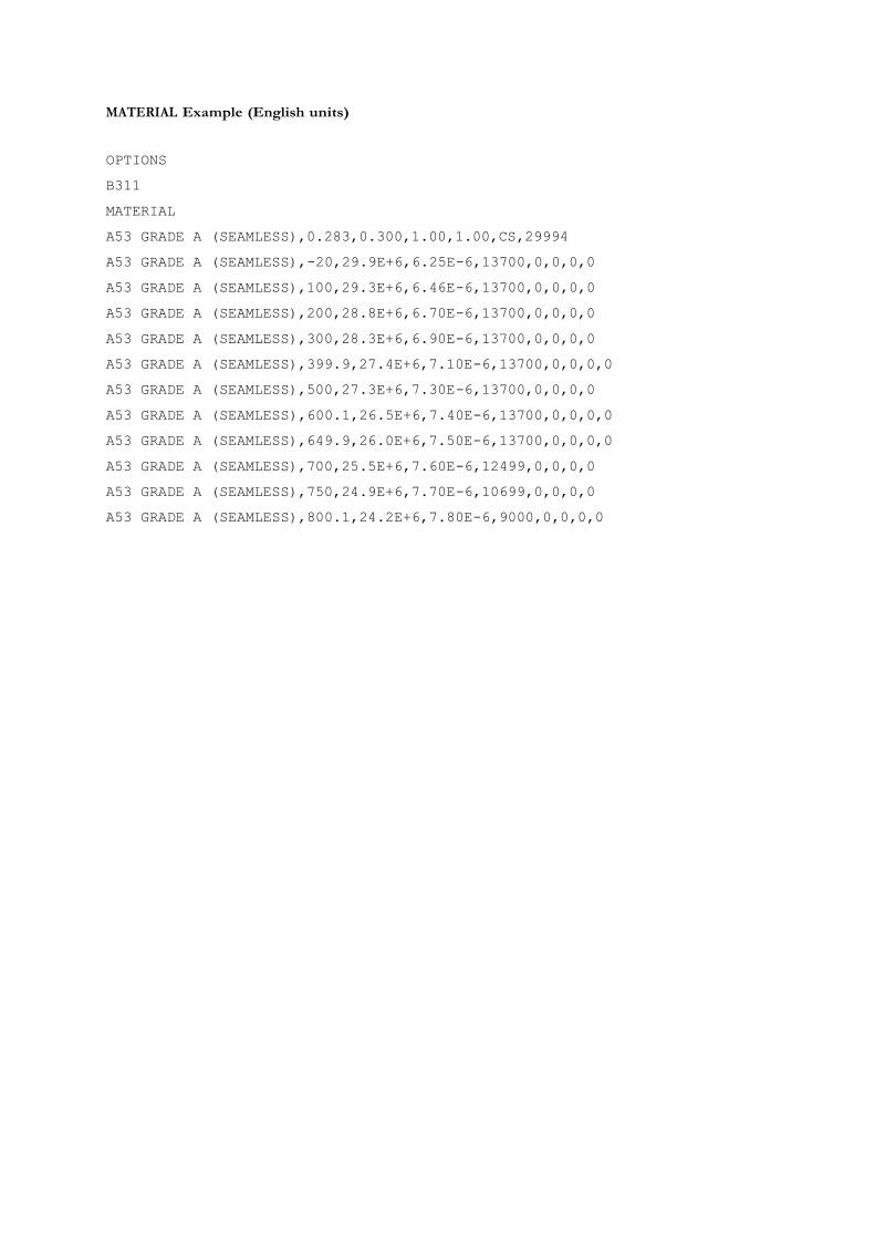
MATERIAL Example (English units)
OPTIONS
B311
MATERIAL
A53 GRADE A (SEAMLESS),0.283,0.300,1.00,1.00,CS,29994
A53 GRADE A (SEAMLESS),-20,29.9E+6,6.25E-6,13700,0,0,0,0
A53 GRADE A (SEAMLESS),100,29.3E+6,6.46E-6,13700,0,0,0,0
A53 GRADE A (SEAMLESS),200,28.8E+6,6.70E-6,13700,0,0,0,0
A53 GRADE A (SEAMLESS),300,28.3E+6,6.90E-6,13700,0,0,0,0
A53 GRADE A (SEAMLESS),399.9,27.4E+6,7.10E-6,13700,0,0,0,0
A53 GRADE A (SEAMLESS),500,27.3E+6,7.30E-6,13700,0,0,0,0
A53 GRADE A (SEAMLESS),600.1,26.5E+6,7.40E-6,13700,0,0,0,0
A53 GRADE A (SEAMLESS),649.9,26.0E+6,7.50E-6,13700,0,0,0,0
A53 GRADE A (SEAMLESS),700,25.5E+6,7.60E-6,12499,0,0,0,0
A53 GRADE A (SEAMLESS),750,24.9E+6,7.70E-6,10699,0,0,0,0
A53 GRADE A (SEAMLESS),800.1,24.2E+6,7.80E-6,9000,0,0,0,0

Export
CAEPIPE can export material properties to a batch text file with the extension .mlb (material library batch file). The text file may be edited using a text editor / using MS Excel. The edited text file may be read back into CAEPIPE by using the Import feature.
To export the material properties, select the menu command File > Export from the Material Library Layout window.
The Export Material Library dialog is shown. Click on the Export button to write to the batch file.