cad estandars
TRANSCRIPT

8/14/2019 CAD ESTANDARS
http://slidepdf.com/reader/full/cad-estandars 1/38
City and County of Denver
Department of Public Works
Wastewater Management Division
CAD Standards
Manual
May 1999

8/14/2019 CAD ESTANDARS
http://slidepdf.com/reader/full/cad-estandars 2/38
MEMORANDUM
DATE: May 14, 1999
TO: Holders of the WMD CAD Standards Manual
FROM: Daniel R. Roberts, P.E.
Workgroup CAD Manager
SUBJECT: May 1999 Update to WMD CAD Standards Manual
Attached is an update of Wastewater Management Division’s CAD Standards Manual, prepared for use by
WMD Design Engineering staff in the preparation of design drawings for WMD projects. Since minor
modifications were made throughout the manual, this update replaces in its entirety the previous release of
the manual issued in May 1999. All custom files are now on the network.
This manual presents standards which generally follow those used by CDOT, with modifications to better
fit WMD projects. While this manual was developed specifically for use on WMD projects, other agencies
are welcome to use it as a model for their standards; for this reason, the distribution of this manual extends
outside of the WMD Design Engineering Workgroup. Eventually, the manual will be available from the
WMD Design Engineering Web page.
The major revisions are as follows:
• Tree and survey symbols have been modified
• Layer standards added for profile layers
• New Land Development Desktop terminology replaces old Softdesk terms and structure
• Description key modifications (BR* changed to BRWLK*, CL* to CL, FS* to FS; some symbol
revisions)
Most of these revisions will be transparent to the WMD Design workgroup since they are defaults stored
on the network.
If you have comments, proposed improvements, or questions about the manual please contact me at (303)446-3648.
attachment

8/14/2019 CAD ESTANDARS
http://slidepdf.com/reader/full/cad-estandars 3/38
Wastewater Management Division CAD Standards Manual
i May 15, 1999
TABLE OF CONTENTS
Page
List of Figures and Tables........................................................................................................................ii
I. Introduction ......................... ........................... ........................... ........................... ........................... .. 1
A. Purpose of Manual.......................... .......................... ........................... ........................... ....... 1
B. Scope.....................................................................................................................................1
II. The Engineering CAD System ......................... ........................... ........................... ........................... .. 2
A. Software Applications and Versions .......................... ........................... ........................... ....... 2
1. Drafting Software ........................ .......................... ........................... ......................... 2
2. Design Software............................................ ........................... ........................... ....... 2
B. Software Customization........................... .......................... ........................... ......................... 2
C. Network Files (Symbols and Templates)............................. ........................... ......................... 2
III. Project Planning and Setup................ .......................... ........................... ........................... ................ 3
A. Project-Specific Standards ........................... ........................... ........................... .................... 3
B. Project Base Points ......................... .......................... ........................... ........................... ....... 3
C. Project Documentation........................ ........................... ........................... ........................... .. 3IV. Drawing and Design Files .......................... .......................... ........................... ........................... ....... 4
A. Drawing File and Land Development Desktop Design File Subdirectory Structure .................. 4
B. Drawing File Naming Conventions........................ ........................... ........................... ........... 4
V. Drawing Setup and Structure....................... .......................... ........................... ........................... ....... 6
A. Use of Model Space and Paper Space........................ ........................... ........................... ....... 6
B. Plan Sheet and Drawing Border Size ......................... ........................... ........................... ....... 6
C. Drawing Scales........ ........................... ........................... ........................... ........................... .. 6
D. XREF’s.................................................................................................................................6
VI. Drafting Procedures .......................... .......................... ........................... ........................... ................ 7
A. Order of Plan Sheets ........................... ........................... ........................... ........................... .. 7
B. Title Block........................ ........................... ........................... ........................... .................... 7
C. Drafting Details, North Arrow, Scale Bars, and Legends ........................... ........................... .. 7
D. Notes.....................................................................................................................................8
E. Signature Blocks....................................................................................................................8
VII. Layers, Colors, and Linetypes..... ........................... ........................... ........................... .................... 9
A. Layer Naming Conventions - Model Space Entities...................... ........................................... 9
1. Geographic Layering Style ........................ ........................... ........................... ........... 9
2. Non-Geographic Layering Style ......................... ........................... ........................... 10
B. Layer Naming Conventions - Paper Space Entities.................................................. .............. 13
C. Colors and Linetypes .......................... ........................... ........................... ........................... 13
D. Pen Weights .......................... .......................... ........................... ........................... .............. 13
VIII. Annotation...................................... .......................... ........................... ........................... .............. 15
A. Text Styles ....................... ........................... ........................... ........................... .................. 15B. Dimensioning.................... ........................... ........................... ........................... .................. 15
C. Symbols............................ ........................... ........................... ........................... .................. 15
IX. Land Development Desktop Files ........................ .......................... ........................... ....................... 16
A. Project Description Keys................. .......................... ........................... ........................... ..... 16
B. Figures Prefix Library......................... ........................... ........................... ........................... 16
Appendix A through Appendix E Index on Page 17

8/14/2019 CAD ESTANDARS
http://slidepdf.com/reader/full/cad-estandars 4/38
Wastewater Management Division CAD Standards Manual
ii May 15, 1999
LIST OF FIGURES AND TABLES
Page
Figure 1 - Drawing File Directory Structure....................... ........................... ........................... ................ 4
Table 1- Recommended File Naming Convention..................... ........................... ........................... ........... 5
Table 2- Layering Style by Drawing Type.... ........................... ........................... ........................... ........... 9
Table 3 - Layer Name Prefixes, First Character (Geographic and Non-Geographic Styles) ...................... 10
Table 4 - Layer Name Prefixes, Second Character (Non-Geographic Only)........................................ ..... 10
Table 5 - Descriptive Layer Names (Geographic Layering Style) .......... ............................................. ..... 11
Table 6 - Descriptive Layer Names - R.O.W. (Geographic Layering Style)........................................ ..... 12
Table 7 - Material and Hatching Items (Non-Geographic Layering Style)....... ......................................... 12
Table 8 - Control and Misc. Items (Non-Geographic Layering Style) ........................................ .............. 12
Table 9 - Paper Space Layering (Non-Discipline Page Items)................ ............................................. ..... 13
Table 10 - Colors and Pen Weights ....................... ........................... ........................... ........................... 14
Table 11 - Fonts and Styles .......................... ........................... ........................... ........................... ......... 15
Table 12 - Figure Prefix Library ........................... ........................... ........................... ........................... 16
8/14/2019 CAD ESTANDARS
http://slidepdf.com/reader/full/cad-estandars 5/38
Wastewater Management Division CAD Standards Manual
Page 1 May 15, 1999
I. Introduction A. Purpose of Manual
This manual was developed to provide Computer Aided Design (CAD) standards and
guidelines for use by WMD Design staff in the design and drafting of storm and sanitary
sewer projects in the City and County of Denver. The manual also serves as a guideline
for consultants performing design of storm and sanitary systems to be constructed in
Denver. Because of the rapidly changing technologies used in engineering design and
drafting, this manual should be considered a “living” document, which will change as
technologies change. Any comments or recommendations about this manual should be addressed to:
CAD Manager - Design Engineering Wastewater Management Division
2000 W. 3rd Ave. Denver, CO 80223 Phone: (303) 446-3648 Fax: (303) 446-3647 B. Scope
This manual covers the basic preparation of project plans using CAD as the method of
plan preparation. Elements covered are the CAD system; project initiation and startup;
drawing file directory structure and file naming conventions; drawing setup; drawing set
structure; drafting procedures; layers, linetypes, and colors; annotation, hatching, and
symbols; and pen weights and plotting procedures.
The standards discussed in this manual generally follow those outlined in CDOT’s Design
Manual Volume IV (Computer Aided Drafting), dated January, 1996, modified to meet the
requirements of WMD design projects. As the use of computers in engineering design evolves, discussion of other elements in the
CAD process may be added to the manual.

8/14/2019 CAD ESTANDARS
http://slidepdf.com/reader/full/cad-estandars 6/38
Wastewater Management Division CAD Standards Manual
Page 2 May 15, 1999
II. The Engineering CAD System The Engineering CAD System used by WMD Design Engineering is comprised of networked CAD
Workstations running Windows NT operating system. Design software is installed on each
individual system; the network provides file, printer, and plotter sharing, as well as access to e-
mail, internet, and other shared resources. The purpose of this system is to provide engineers and
drafters with state-of-the-art tools for use in design, maximizing the productivity of the workgroup. A. Software Applications and Versions
1. Drafting Software AutoCad is the drafting software package used by WMD Design Engineering.
Each workstation is provided with the latest version of AutoCad. All drawings
used by, or provided to, the workgroup shall be dwg (AutoCad native) format. 2. Design Software
AutoDesk’s Land Development Desktop (LDD) with Civil Design and Survey is
the software package used by WMD Design Engineering to perform engineering
design in AutoCad. The package provides the user with tools to perform survey
data import, surface modeling, horizontal and vertical alignment design, and pipe
system design, and other design tasks. Survey data provided to the workgroup
shall be a format useable by this design package - either ASCII text or fbk ( Land
Development Desktop native fieldbook) format. B. Software Customization
The WMD Design Engineering workgroup uses a customized symbol set, custom defined
lines, and custom fonts, as discussed in following sections of this manual. Several files
have been developed as part of this customization package. For a copy of these files,
contact the workgroup CAD Manager, as noted on page 1 of this manual. C. Network Files (Symbols and Templates)
All AutoDesk products (AutoCad, Land Development Desktop, Civil Design, and Survey)
are licensed as network versions and run under a client deployment scenario with programs
installed on local machines and LDD projects and data files located on the network.
Symbols, templates, and other LDD data files are managed by the CAD Manager and are
“read only” for users. Templates exist for basemaps, title sheets, general notes sheets, and
detail sheets.

8/14/2019 CAD ESTANDARS
http://slidepdf.com/reader/full/cad-estandars 7/38
Wastewater Management Division CAD Standards Manual
Page 3 May 15, 1999
III. Project Planning and Setup
A. Project-Specific Standards The standards described in this manual will be applicable to the majority of the storm and
sanitary system design projects performed by the workgroup. However, there will be
projects where a variance from these standards will provide a better methodology - an
example of this is the completion of a project which was started before the implementation
of these standards. In cases where the use of these standards would require a significant
amount of re-work, then project-specific standards are acceptable. The use of project-
specific standards should be documented with the archived set of project files. B. Project Base Points
The use of a project-specific coordinate system is acceptable for WMD design projects.
The coordinate system used for design should match that used by the surveyor for data
collection - points should not be rotated or translated. AutoCad’s X,Y base point of 0,0should match a Northing, Easting of 0,0. WMD projects shall use City of Denver published bench marks for vertical control. With the increased use of GPS equipment, surveyors and designers are encouraged to tie
the project coordinate system to a modified state plane coordinate system. This will
facilitate future use of some of the design elements in a city GIS system. C. Project Documentation
At the completion of each project (end of construction), project files should be archived on
CD-ROM. These files should include the AutoCad drawing files; Land Development
Desktop design files; AutoCad line and font definition files; and all other associated files.
In the future, scanned “as-built” drawings and other project documents such as
correspondence will be included with the archive set. Each archived set should include a “readme” file which describes the archive set, and gives
project information such as project manager, date completed, etc.
8/14/2019 CAD ESTANDARS
http://slidepdf.com/reader/full/cad-estandars 8/38
Wastewater Management Division CAD Standards Manual
Page 4 May 15, 1999
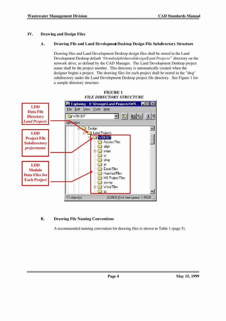
IV. Drawing and Design Files A. Drawing File and Land Development Desktop Design File Subdirectory Structure
Drawing files and Land Development Desktop design files shall be stored in the Land
Development Desktop default “ //wmdralph/shared/design/Land Projects” directory on the
network drive, as defined by the CAD Manager. The Land Development Desktop project
name shall be the project number. This directory is automatically created when the
designer begins a project. The drawing files for each project shall be stored in the "dwg"
subdirectory under the Land Development Desktop project file directory. See Figure 1 for
a sample directory structure. FIGURE 1 FILE DIRECTORY STRUCTURE
B. Drawing File Naming Conventions A recommended naming convention for drawing files is shown in Table 1 (page 5).
LDD
Data FileDirectory
Land Projects
LDD
Project File
Subdirectory
projectname
LDD
ModuleData Files for
Each Project

8/14/2019 CAD ESTANDARS
http://slidepdf.com/reader/full/cad-estandars 9/38
Wastewater Management Division CAD Standards Manual
Page 5 May 15, 1999
TABLE 1 RECOMMENDED FILE NAMING CONVENTION
File Name Description Notes
TS.DWG Title Sheet
SP.DWG Standard Plans List
TYxx.DWG Typical Sections Sheets TY sheet "xx" (01, 02, etc.)GN.DWG General Notes and Legend
SQxx.DWG Summary of Quantity Sheets SQ sheet “xx” (01, 02, etc.)
TABxx.DWG Tabulation Sheets TAB sheet "xx" (01, 02, etc.)
DTxx.DWG Detail Sheets DT sheet “xx” (01, 02, etc.)
PPxx.DWG Plan and Profile Sheets PP sheet “xx” (01, 02, etc.)
SCxx.DWG Survey Control Sheets SC sheet "xx" (01, 02, etc.)
KCSxx.DWG Known Contamination Sites KCS sheet "xx" (01, 02, etc.)
LSxx.DWG Landscape Plan Sheets LS sheet "xx" (01, 02, etc.)
WMxx.DWG Wetland Mitigation Sheets WM sheet "xx" (01, 02, etc.)
SWMPxx.DWG Stormwater Management Plan SWMP sheet "xx" (01, 02, etc.)
TCxx.DWG Traffic Control Sheets TC sheet “xx” (01, 02, etc.)SSxx.DWG Signing and Striping Plan SS sheet "xx" (01, 02, etc.)
BASE.DWG Project basemap
PROFILE.DWG Profile Drawing
XRROW.DWG ROW (X-REF) “XR” indicates X-REF
Additional drawing files shall be named using a similar convention and the components of
each drawing shall be documented in the “readme” file of the archive set.
8/14/2019 CAD ESTANDARS
http://slidepdf.com/reader/full/cad-estandars 10/38
Wastewater Management Division CAD Standards Manual
Page 6 May 15, 1999
V. Drawing Setup and Structure In order for project team members to easily share work on a project, it is important that the method
of drafting and the structure of the drawing set be standardized. The following subsections provide
guideline for this standardization. A. Use of Model Space and Paper Space
All drafting shall be done at 1:1 (1 AutoCad unit = 1 foot), in engineering units, in the
AutoCad model space environment. Plotting shall be done using the plot layout tools of
AutoCad’s paper space environment; drawing sheets shall be set up at a scale of 1:1, and
views in the drawing shall be scaled using viewport scaling. In addition to the drawing
border, other entities to be placed in paper space include general notes, north arrow and
scale bar, and sheet-specific legends. If Land Development Desktop’s Sheet Manager
tools are used, then profile and cross-section grids should be drawn in paper space. B. Plan Sheet and Drawing Border Size
The standard plan sheet shall be 22” x 34”; the border shall be 21” x 32”, and shall be
1/2” from the edge of the sheet at the top, right, and bottom, and 1 1/2” from the left edge
of the sheet. Typically, plan sets provided for bidding and construction shall be half-scale drawings
(11” x 17”). A sample half-scale border is included in the appendix of this manual.
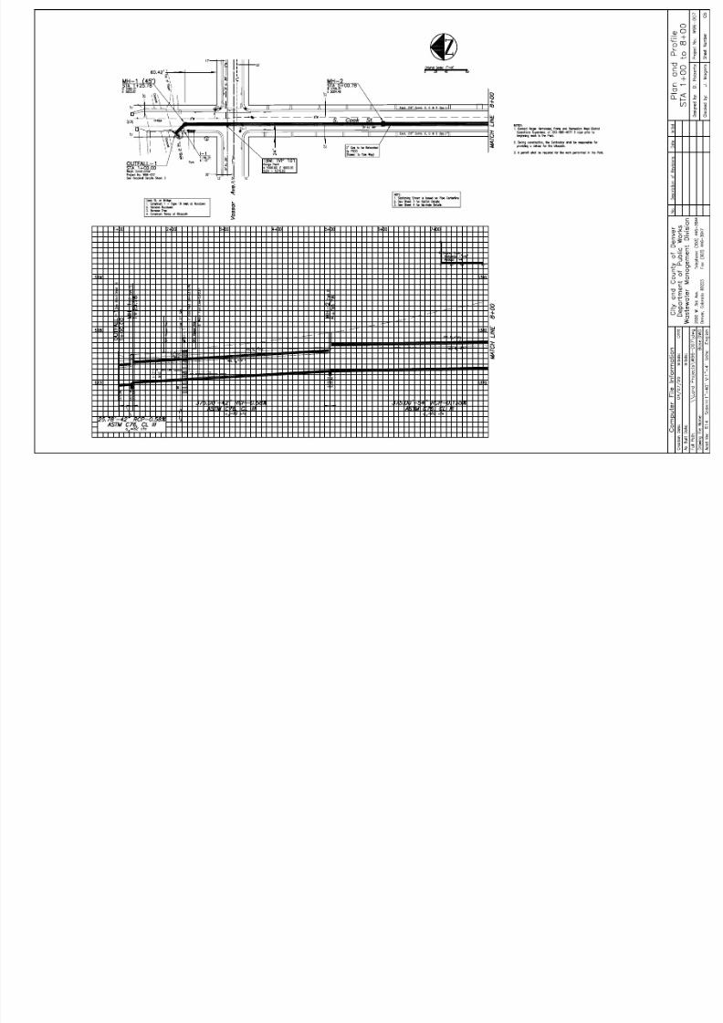
C. Drawing Scales The standard scale to be used for plan and profile sheets shall be 1”=40’ for full-size
drawings. In areas where greater detail is required, scales of 1”=10’ and 1”=20’ shall be
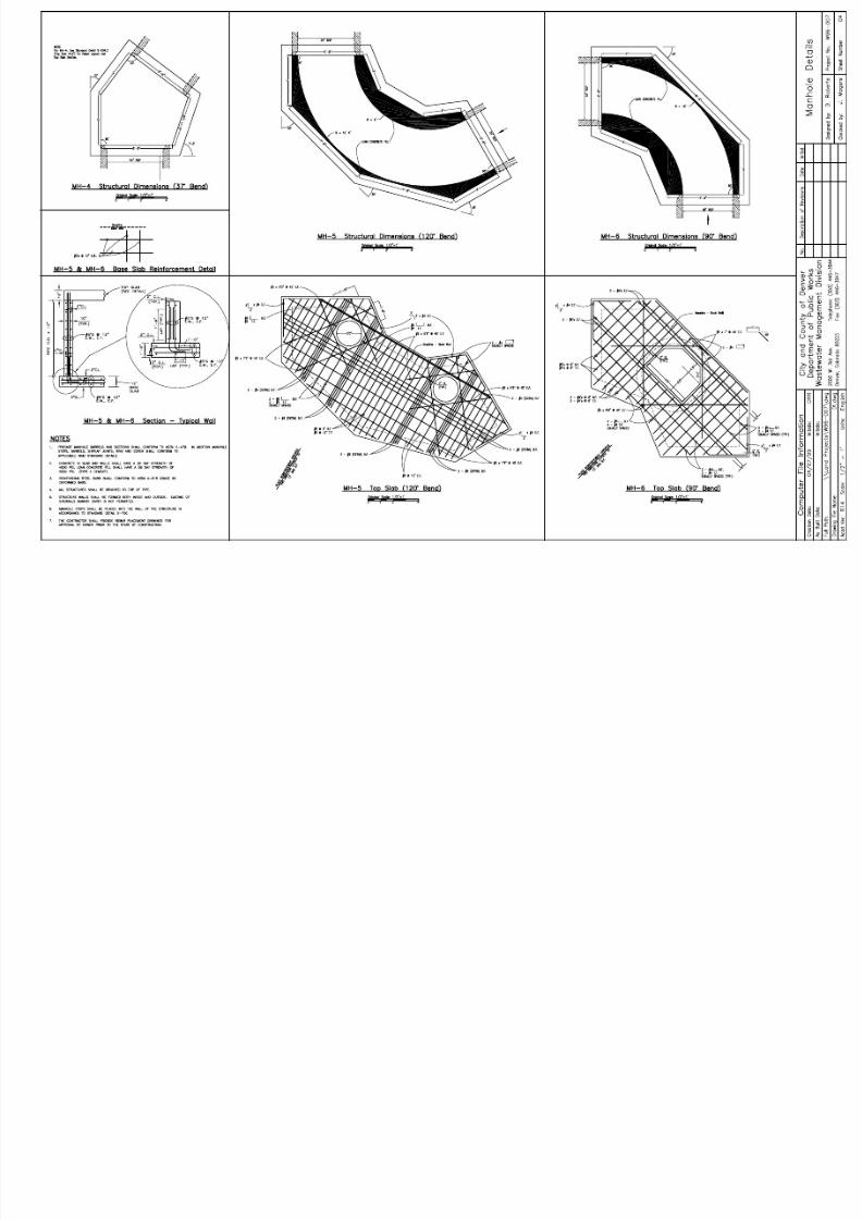
used. Other engineering scales may be used if warranted by special considerations. Drafters are encouraged to include standards details such as manholes and inlets as scaled
details rather than as “ Not to Scale” (N.T.S.) drawings. D. XREF’s
For small projects with five or less plan sheets, it is acceptable to place all components of
the plan and profile in the model space of a single base drawing, and all of the sheets in the
paper space of the same drawing. For larger projects, where drawing size effectscomputer performance, the base drawing should contain the plan view and the profile
should be drawn in a separate drawing. These two drawings should then be XREF’d into
a third drawing containing a plan and profile sheet for plotting. With this method, each
plan and profile sheet should be a separate drawing. XREFs should also be used wherever a part of the basemap or other information will be
used in more than one drawing, so that any changes are automatically updated in all of the
associated drawings.
8/14/2019 CAD ESTANDARS
http://slidepdf.com/reader/full/cad-estandars 11/38
Wastewater Management Division CAD Standards Manual
Page 7 May 15, 1999
VI. Drafting Procedures A. Order of Plan Sheets
Listed below is the sheet order for a set of construction plans. In a typical project, only
part of the sheets listed will be needed.
Plan Sheet Order Title Sheet Standard Plan List Sheet Typical Sections Sheet General Notes and Legend Sheet Summary of Approximate Quantities Tabulation Sheets Detail Sheets Plan and Profile Sheets Major “Specialized Group” Sheets
− Survey Control Sheets− Known Contamination Sites Plan
− Landscaping Sheets
− Wetland Mitigation Sheets
− Stormwater Management Plan Sheets
− Traffic Control Sheets
− Final Signing and Striping Sheets Plan sheets should be numbered sequentially in the final construction set (1,2,3... etc.)
B. Title Block Each sheet shall have a title block which shall include computer file information, the sheet
name, project number, sheet number, the designer and reviewer, and a revision block. The
sample border in the appendix includes a sample title block. The title block shall be located along the right edge of the border and shall read from the
right side of the border, so that the title block shall be at the top of archived drawings in
WMD’s vertical file cabinets. C. Drafting Details, North Arrow, Scale Bars, And Legends
Drawing details such as section callouts and detail callouts are illustrated in the appendix.
These details are a part of the WMD custom symbol set and can be obtained from theCAD Manager. Each plan and profile sheet shall contain a north arrow and scale bar in the plan view, and
a scale bar in the profile view, typically in the upper right corner of each view. The
appendix contains examples of these details. These details are also part of the WMD
custom symbol set.
8/14/2019 CAD ESTANDARS
http://slidepdf.com/reader/full/cad-estandars 12/38
Wastewater Management Division CAD Standards Manual
Page 8 May 15, 1999
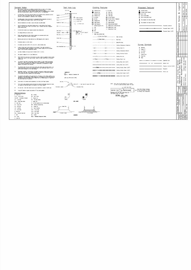
Each drawing set shall include a legend for the set. The legend shall typically be included
on the “General Notes and Legend” sheet. For special symbols used only on one or two
sheets, the legend for those symbols may be included on the applicable sheets. A sample “ General Notes and Legend” sheet is included in the appendix.
D. Notes General notes for each drawing set shall be included on the “General Notes and Legend”
sheet. Notes specific to an individual sheet, or to a set of specialized sheets, may be
included on those individual sheets. E. Signature Blocks
Each plan set shall include a City and County Of Denver, Department of Public Works
approval signature block, which must be completely signed before the project may be
advertised for construction. The signatures to be included on WMD Design Engineering
projects are (in the order that they appear on the approval block): * Manager of Public Works Executive Director UDFCD Chief of UDFCD Design and Construction Program * Deputy Manager for Wastewater Management Deputy Manager for Transportation City Engineer Manager of Parks and Recreation * Mayor’s Office of Contract Compliance (* always required)
In addition to the approval block, each plan set should include a submittal block, which
shall include the following: Project Design Engineer Chief Design Engineer Director of Engineering
These signature blocks shall be included on the cover sheet of each project. See the
appendix of this manual for a sample cover sheet.
8/14/2019 CAD ESTANDARS
http://slidepdf.com/reader/full/cad-estandars 13/38
Wastewater Management Division CAD Standards Manual
Page 9 May 15, 1999
VII. Layers, Colors, and Linetypes A. Layer Naming Conventions - Model Space Entities
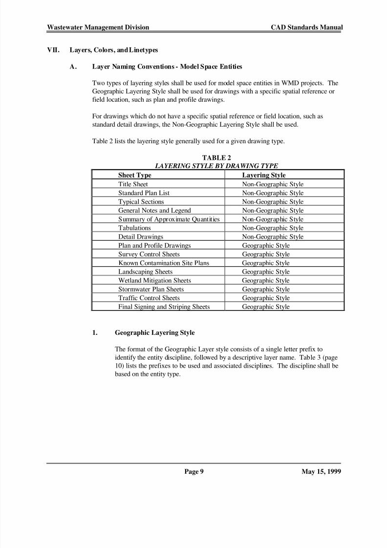
Two types of layering styles shall be used for model space entities in WMD projects. The
Geographic Layering Style shall be used for drawings with a specific spatial reference or
field location, such as plan and profile drawings. For drawings which do not have a specific spatial reference or field location, such as
standard detail drawings, the Non-Geographic Layering Style shall be used. Table 2 lists the layering style generally used for a given drawing type.
TABLE 2 LAYERING STYLE BY DRAWING TYPE
Sheet Type Layering Style
Title Sheet Non-Geographic Style
Standard Plan List Non-Geographic StyleTypical Sections Non-Geographic Style
General Notes and Legend Non-Geographic Style
Summary of Approximate Quantities Non-Geographic Style
Tabulations Non-Geographic Style
Detail Drawings Non-Geographic Style
Plan and Profile Drawings Geographic Style
Survey Control Sheets Geographic Style
Known Contamination Site Plans Geographic Style
Landscaping Sheets Geographic Style
Wetland Mitigation Sheets Geographic Style
Stormwater Plan Sheets Geographic StyleTraffic Control Sheets Geographic Style
Final Signing and Striping Sheets Geographic Style
1. Geographic Layering Style
The format of the Geographic Layer style consists of a single letter prefix to
identify the entity discipline, followed by a descriptive layer name. Table 3 (page
10) lists the prefixes to be used and associated disciplines. The discipline shall be
based on the entity type.

8/14/2019 CAD ESTANDARS
http://slidepdf.com/reader/full/cad-estandars 14/38
Wastewater Management Division CAD Standards Manual
Page 10 May 15, 1999
TABLE 3
LAYER NAME PREFIXES FIRST CHARACTER (GEOGRAPHIC AND NON-GEOGRAPHIC STYLES)
First
Character
Discipline
Second
Character
Option
Discipline
Name
Included Entities
C none,C,H,M,P Construction Construction As-Built information
D none,C,H,M,P Design Design graphics, text, notes
E none,C,H,M,P Existing Existing graphics, text, notes such as utilities from
utility maps
P none Profile Design Profile
R none,C,H,M,P Right-of-Way Existing Right-of-Way
S none,C,H,M,P Survey Survey points from design survey
T none,C,H,M,P Traffic Traffic graphics, text, notes (construction zone and
final signing and striping)
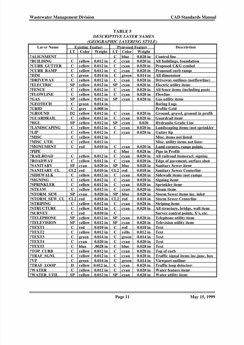
Table 5 on page 11 and Table 6 on page 12 list descriptive layer names to be used.
The “?” should be replaced by first character prefix from Table 3: for example,
the layer name for a proposed (“design”) storm sewer (in plan view) would be
“DSTORM_SEW”. Table 5 should be considered as a guideline and can be expanded for individual
projects as needed. 2. Non-Geographic Layering Style
The format of the Non-Geographic Layering style consists of a two letter prefix to
identify the entity discipline (first letter) and option (second letter), followed by adescriptive layer name. Tables 3 and 4 list the prefixes to be used.
TABLE 4
LAYER NAME PREFIXES
SECOND CHARACTER (NON-GEOGRAPHIC ONLY)
Second
Character
Option
Character Description
C Control item layers (control line, etc.)
H Hatching layers
M Material layers
Descriptive layer names for material and hatching items are listed in Table 7 on
page 12, and for control and misc. items in Table 8 on page 12.
8/14/2019 CAD ESTANDARS
http://slidepdf.com/reader/full/cad-estandars 15/38
Wastewater Management Division CAD Standards Manual
Page 11 May 15, 1999
TABLE 5
DESCRIPTIVE LAYER NAMES
(GEOGRAPHIC LAYERING STYLE)
La er Name Existin Featur Pro osed Featur Descri tionLT Color Weight LT Color Weight
?ALIGNMENT C blue 0.028 in Control lin
?BUILDING C yellow 0.012 in C cyan 0.020 in All buildings, foundation?CURB_GUTTER C yellow 0.012 in C cyan 0.020 in Proposed C&G symbol
?CURB_RAMP C yellow 0.012 in C cyan 0.020 in Proposed curb ramp
?DIM C green 0.014 in C green 0.014 in All dimension
?DRIVEWAY C yellow 0.012 in C cyan 0.020 in Driveway outlines (not flowline)
?ELECTRIC SP yellow 0.012 in SP cyan 0.020 in Electric utility item
?FENCE C yellow 0.012 in C cyan 0.020 in All fence items (including posts
?FLOWLINE C yellow 0.012 in C cyan 0.020 in Flowlin
?GAS SP yellow 0.012 in SP cyan 0.020 in Gas utility item
?GEOTECH C green 0.014 in Boring Logs
?GRID C grey 0.008 in Profile Grid
?GROUND D2 yellow 0.012 in C cyan 0.020 in Ground, gravel, ground in profil
?GUARDRAIL C yellow 0.012 in C cyan 0.020 in Guardrail item
?HGL SP yellow 0.012 in SP cyan 0.020 Hydraulic Grade Lin
?LANDSCAPING C yellow 0.012 in C cyan 0.020 in Landscaping items (not sprinkler
?LIP C yellow 0.012 in C cyan 0.020 in Gutter lip
?MISC C yellow 0.012 in Misc. items not listed
?MISC_UTIL C yellow 0.012 in Misc. utility items not liste
?MONUMENT C red 0.010 in C cyan 0.020 in Land corners, range points
?PIPE C blue 0.028 in Pipe in Profil
?RAILROAD C yellow 0.012 in C cyan 0.020 in All railroad items excl. signin
?ROADWAY C yellow 0.012 in C cyan 0.020 in Edge of pavement, surface shot
?SANITARY SP cyan 0.020 in SP blue 0.028 in Sanitary Sewer item
?SANITARY_CL CL2 red 0.010 in CL2 red 0.010 in Sanitary Sewer Centerlin
?SIDEWALK C yellow 0.012 in C cyan 0.020 in Sidewalk items (not ramps
?SIGNING C yellow 0.012 in C cyan 0.020 in Signing item?SPRINKLER C yellow 0.012 in C cyan 0.020 in Sprinkler item
?STEAM C yellow 0.012 in C cyan 0.020 in Steam item
?STORM_SEW SP cyan 0.020 in SP blue 0.028 in Storm Sewer items inc. inlet
?STORM_SEW_CL CL2 red 0.010 in CL2 red 0.010 in Storm Sewer Centerlin
?STRIPING C yellow 0.012 in C cyan 0.020 in Striping item
?STRUCTURE C yellow 0.012 in C cyan 0.020 in All structure, bridge, wall item
?SURVEY C red 0.010 in C Survey control points, X’s, etc.
?TELEPHONE SP yellow 0.012 in SP cyan 0.020 in Telephone utility item
?TELEVISION SP yellow 0.012 in SP cyan 0.020 in Television utility item
?TEXT1 C red 0.010 in C red 0.010 in Text
?TEXT2 C yellow 0.012 in C yello 0.012 in Text
?TEXT3 C green 0.014 in C green 0.014 in Text
?TEXT4 C cyan 0.020 in C cyan 0.020 in Text?TEXT5 C blue .0028 in C blue 0.028 in Text
?TOP_CURB C yellow 0.012 in C cyan 0.020 in Top of curb
?TRAF_SGNL C yellow 0.012 in C cyan 0.020 in Traffic signal items inc. junc. box
?VP C green 0.014 in C green 0.014 in Viewport outline
?TRAF_LOOP D yellow 0.012 in. C cyan 0.020 in Traffic loop detector
?WATER C yellow 0.012 in C cyan 0.020 in Water feature item
?WATER_UTIL SP yellow 0.012 in SP cyan 0.020 in Water utility item

8/14/2019 CAD ESTANDARS
http://slidepdf.com/reader/full/cad-estandars 16/38
Wastewater Management Division CAD Standards Manual
Page 12 May 15, 1999
TABLE 6
DESCRIPTIVE LAYER NAMES - R.O.W.
(GEOGRAPHIC LAYERING STYLE)
La er Name Existin Featur Pro osed Feature Descri tionLT Color Weight LT Color Weight
REASEMENT P2 reen 0.014 in P2 reen 0.014 in Easement lineRLANDLINE P cyan 0.020 in P cyan 0.020 in Section, quartersection line
RPROPERTY C cyan 0.020 in C cyan 0.020 in Property lines that are not R.O.W
RRANGELINE SP red 0.010 in SP red 0.010 in Rangeline
RROW C blue 0.028 in C blue 0.028 in R.O.W. lines (streets and alleys
RTEXT2 C yellow 0.012 in C yellow 0.012 in Range line and dimension tex
RTEXT5 C blue 0.028 in C blue 0.028 in Street name tex
TABLE 7
MATERIAL AND HATCHING ITEMS
(NON-GEOGRAPHIC LAYERING STYLE)La er Name LT Color Wei ht Descri tion
??ASPHALT C c an 0.020 in As halt material outline, hatc??BASECOURSE C green 0.014 in Base course outline, hatc
??CONCRETE C cyan 0.020 in Concrete material outline, hatc
??EMBANKMENT C green 0.014 in Embankment outline, hatc
??METAL C cyan 0.020 in Metal material outline, hatc
??PLASTIC C green 0.014 in Plastic material outline, hatc
??REBAR C blue 0.028 in Rebar outline, hatc
??RIPRAP C green 0.014 in Stone material outline, hatc
??SUBGRADE C green 0.014 in Subgrade outline, hatc
??TOPSOIL C green 0.014 in Topsoil outline, hatc
??WIRE C yellow 0.012 in Wire outline, hatc
??WOOD C green 0.014 in Wood material outline, hatc
??* C green 0.014 in Replace “*” with material nam
Note: all hatching shall be gray (color 8) and weight = 0.008 in
TABLE 8
CONTROL AND MISC. ITEMS
(NON-GEOGRAPHIC LAYERING STYLE)
La er Name LT Color Wei ht Descri tion
?CBOX C green 0.014 in Table boxes, detail borde?CCENTER C red 0.010 in Center line
?CHIDDEN H yellow 0.012 in Hidden line
?CORIGINAL D red 0.010 in Original materia
?CSYMBOLS C cyan 0.020 in Symbols, etc.
?CTEXT1 C red 0.010 in Text
?CTEXT2 C yellow 0.012 in Text
?CTEXT3 C green 0.014 in Text
?CTEXT4 C cyan 0.020 in Text
?CTEXT5 C blue .0028 in Text

8/14/2019 CAD ESTANDARS
http://slidepdf.com/reader/full/cad-estandars 17/38
Wastewater Management Division CAD Standards Manual
Page 13 May 15, 1999
B. Layer Naming Conventions - Paper Space Entities Entities in paper space include the drawing border, general notes, north arrow and scale
bar(s), and other page items. Layer names for these non-discipline page items are listed in
Table 9.
TABLE 9
PAPER SPACE LAYERING
(NON-DISCIPLINE PAGE ITEMS)
ZPBORDER C blue 0.028 in Drawin border
ZPBOX C green 0.014in Table boxe
ZPDATESTAMP C red 0.010 in Drawing date stamp
ZPDIM C green 0.014 in Dimension
ZPGRIDMAJOR C green 0.014 in Profile grid when in Paperspac
ZPGRIDMINOR C 8 0.008 in Profile grid when in Paperspac
ZPLOC_MAP C yellow 0.012 in Location Map (Title Sheet
ZPMATCHLINE C blue 0.028 in Match line
ZPSYMBOL C blue 0.028 in Symbols (N. Arrow, Seal, et.)
ZPTEXT1 C red 0.010 in TextZPTEXT2 C yellow 0.012 in Text
ZPTEXT3 C green 0.014 in Text
ZPTEXT4 C cyan 0.020 in Text
ZPTEXT5 C blue .0028 in Text
ZPVP C green 0.014 in View ports
C. Colors and Linetypes Colors and linetypes of entities shall generally be defined “bylayer” and shall be as shown
in Tables 5 through 9. Linetypes shown (“LT” ) are AutoCad standard linetypes, as shownbelow: C = Continuous D = Dashed P = Phantom P2 = Phantom2 CL2 = Center2 Linetypes listed as “SP” are special WMD custom linetypes; for entities with special
linetypes, the color shall be “bylayer” and linetype shall be by entity. WMD custom
linetypes are shown on the sample “General Notes and Legend” sheet in the appendix.
D. Pen Weights
Plotted pen weights and corresponding AutoCad colors for full-scale drawings are listed in
Table 10 on page 14. Drafting Pen numbers are included for reference. Plotting widths
for half-scale drawings shall be one-half that shown in the table.

8/14/2019 CAD ESTANDARS
http://slidepdf.com/reader/full/cad-estandars 18/38
Wastewater Management Division CAD Standards Manual
Page 14 May 15, 1999
TABLE 10
COLORS AND PEN WEIGHTS
AutoCad
Color No.
AutoCad
Color Name
Pen Weight Drafting
Pen No.
1 Red 0.010 in 3 x 02 Yellow 0.012 in 2 x 0
3 Green 0.014 in 0
4 Cyan 0.020 in 1
5 Blue 0.028 in 2
6 Magenta 0.040 in 3
7 White 0.048 in 4
8 Dark Gray 0.008 in -
9 Light Gray 0.048 in 4
8/14/2019 CAD ESTANDARS
http://slidepdf.com/reader/full/cad-estandars 19/38
Wastewater Management Division CAD Standards Manual
Page 15 May 15, 1999
VIII. Annotation
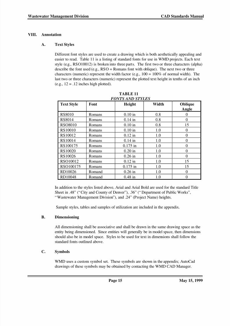
A. Text Styles Different font styles are used to create a drawing which is both aesthetically appealing and
easier to read. Table 11 is a listing of standard fonts for use in WMD projects. Each text
style (e.g., RSO10012) is broken into three parts. The first two or three characters (alpha)
describe the font used (e.g., RSO = Romans font with oblique). The next two or three
characters (numeric) represent the width factor (e.g., 100 = 100% of normal width). The
last two or three characters (numeric) represent the plotted text height in tenths of an inch
(e.g., 12 = .12 inches high plotted). TABLE 11
FONTS AND STYLES
Text Style Font Height Width Oblique
Angle
RS8010 Romans 0.10 in 0.8 0RS8014 Romans 0.14 in 0.8 0
RSO8010 Romans 0.10 in 0.8 15
RS10010 Romans 0.10 in 1.0 0
RS10012 Romans 0.12 in 1.0 0
RS10014 Romans 0.14 in 1.0 0
RS100175 Romans 0.175 in 1.0 0
RS10020 Romans 0.20 in 1.0 0
RS10026 Romans 0.26 in 1.0 0
RSO10012 Romans 0.12 in 1.0 15
RSO100175 Romans 0.175 in 1.0 15
RD10026 Romand 0.26 in 1.0 0RD10048 Romand 0.48 in 1.0 0
In addition to the styles listed above, Arial and Arial Bold are used for the standard Title
Sheet in .48” (“City and County of Denver”), .36” (“ Department of Public Works”,
“Wastewater Management Division”), and .24” (Project Name) heights. Sample styles, tables and samples of utilization are included in the appendix.
B. Dimensioning All dimensioning shall be associative and shall be drawn in the same drawing space as theentity being dimensioned. Since entities will generally be in model space, then dimensions
should also be in model space. Styles to be used for text in dimensions shall follow the
standard fonts outlined above. C. Symbols
WMD uses a custom symbol set. These symbols are shown in the appendix; AutoCad
drawings of these symbols may be obtained by contacting the WMD CAD Manager.
8/14/2019 CAD ESTANDARS
http://slidepdf.com/reader/full/cad-estandars 20/38
Wastewater Management Division CAD Standards Manual
Page 16 May 15, 1999
IX. Land Development Desktop Files
A. Project Description Keys Land Development Desktop uses description keys to automatically sort survey point data
into different layers, to assign descriptions to Land Development Desktop point entities,
and to assign symbols to point entity locations based on the survey point description. This
file has been customized to match WMD standards. A printout of this file has been included in the appendix of this manual.
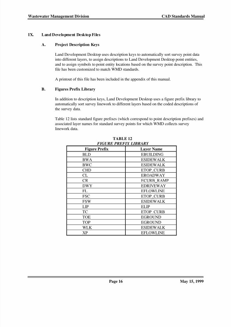
B. Figures Prefix Library
In addition to description keys, Land Development Desktop uses a figure prefix library to
automatically sort survey linework to different layers based on the coded descriptions of
the survey data.
Table 12 lists standard figure prefixes (which correspond to point description prefixes) and
associated layer names for standard survey points for which WMD collects survey
linework data.
TABLE 12
FIGURE PREFIX LIBRARY
Figure Prefix Layer Name
BLD EBUILDING
BWA ESIDEWALK
BWC ESIDEWALK
CHD ETOP_CURBCL EROADWAY
CR ECURB_RAMP
DWY EDRIVEWAY
FL EFLOWLINE
FSC ETOP_CURB
FSW ESIDEWALK
LIP ELIP
TC ETOP_CURB
TOE EGROUND
TOP EGROUND
WLK ESIDEWALKXP EFLOWLINE

8/14/2019 CAD ESTANDARS
http://slidepdf.com/reader/full/cad-estandars 21/38
Wastewater Management Division CAD Standards Manual
Page 17 May 15, 1999
APPENDICES
Appendix A Sample Plan Sheets (half scale)
Sample WMD Border................................ ................................ .sheet 1
Sample Title Sheet................................ ................................ ....... sheet 2
Sample General Notes and Legend................................ ............. sheet 3
Sample Detail Sheet................................ ................................ ..... sheet 4
Sample Plan and Profile Sheet................................ ..................... sheet 5
Appendix B WMD Custom Symbols Library................................ ..............B-1 through B-4
Appendix C WMD Custom Text Styles................................ ................................ ............ C-1
Annotation Style Definition Table................................ ........... C-2 through C-3
Appendix D WMD Land Development Desktop Description Keys............. D-1 through D-4
Appendix E WMD Customization Files
Wmd.lin................................ ................................ ............................ E-1

8/14/2019 CAD ESTANDARS
http://slidepdf.com/reader/full/cad-estandars 22/38

8/14/2019 CAD ESTANDARS
http://slidepdf.com/reader/full/cad-estandars 23/38
8/14/2019 CAD ESTANDARS
http://slidepdf.com/reader/full/cad-estandars 24/38
8/14/2019 CAD ESTANDARS
http://slidepdf.com/reader/full/cad-estandars 25/38
8/14/2019 CAD ESTANDARS
http://slidepdf.com/reader/full/cad-estandars 26/38

8/14/2019 CAD ESTANDARS
http://slidepdf.com/reader/full/cad-estandars 27/38
Wastewater Management Division CAD Standards Manual
B-1 May 15, 1999
WMD Custom Symbol Set
Full Scale Half Scale Symbol Name Description
Wmdbench.dwg bus bench
Wmdbm.dwg benchmark
Wmdbound.dwg property corner
Wmdbox.dwg drinking fountain
Wmdchx.dwg chiseled “x”
Wmdcshrb.dwg coniferous shrub
Wmdctree.dwg coniferous tree
Wmddshrb.dwg deciduous shrub
Wmddtree.dwg deciduous tree
Wmddump.dwg trash dumpster
Wmdemh.dwg existing manhole
Wmdemhsp.dwg existing manhole (special)
Wmdet12.dwg existing type 12 inlet
Wmdet14.dwg existing type 14 inlet
Wmdet16.dwg existing type 16 inlet
Wmdfh.dwg existing fire hydrant
Wmdguy.dwg existing guy wire
8/14/2019 CAD ESTANDARS
http://slidepdf.com/reader/full/cad-estandars 28/38
Wastewater Management Division CAD Standards Manual
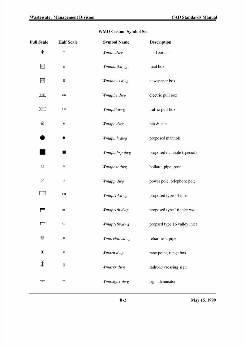
B-2 May 15, 1999
WMD Custom Symbol Set
Full Scale Half Scale Symbol Name Description
Wmdlc.dwg land corner
Wmdmail.dwg mail box
Wmdnews.dwg newspaper box
Wmdpbe.dwg electric pull box
Wmdpbt.dwg traffic pull box
Wmdpc.dwg pin & cap
Wmdpmh.dwg proposed manhole
Wmdpmhsp.dwg proposed manhole (special)
Wmdpost.dwg bollard, pipe, post
Wmdpp.dwg power pole, telephone pole
Wmdpt14.dwg proposed type 14 inlet
Wmdpt16t.dwg proposed type 16 inlet w/o.t.
Wmdpt16v.dwg propsed type 16 valley inlet
Wmdrebar..dwg rebar, iron pipe
Wmdrp.dwg rane point, range box
Wmdrrx.dwg railroad crossing sign
Wmdsign1.dwg sign, delineator
8/14/2019 CAD ESTANDARS
http://slidepdf.com/reader/full/cad-estandars 29/38
Wastewater Management Division CAD Standards Manual
B-3 May 15, 1999
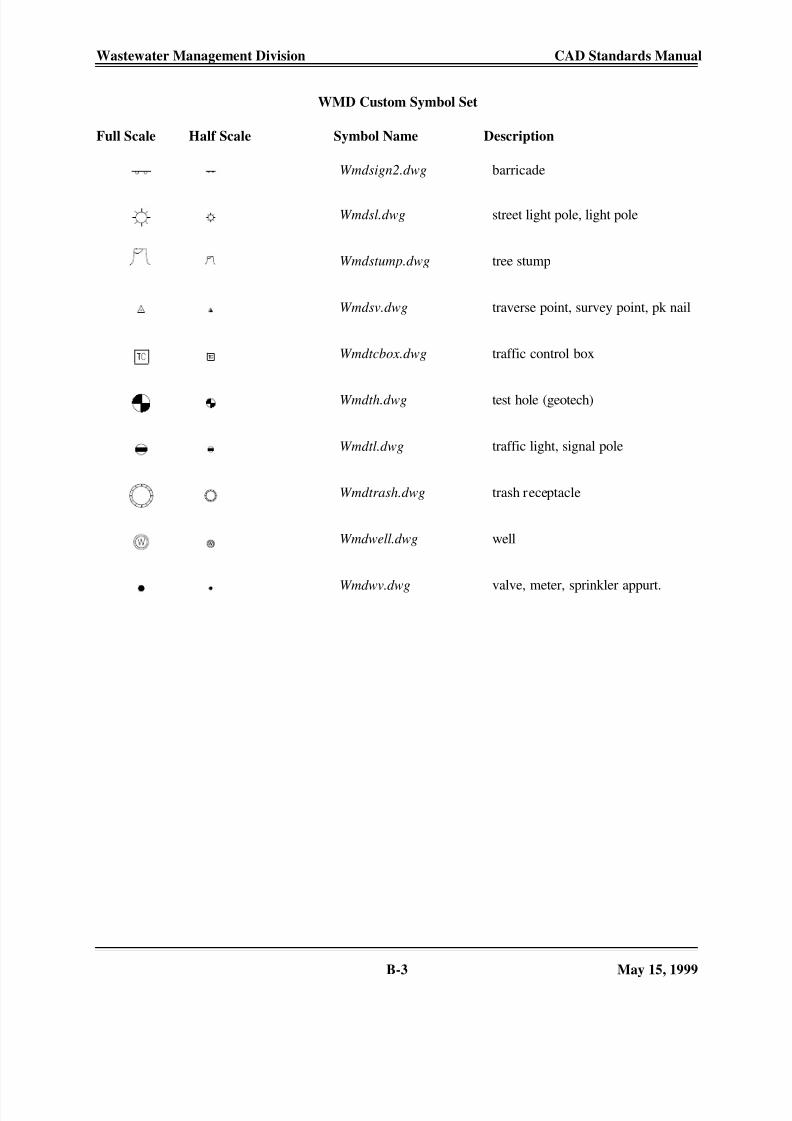
WMD Custom Symbol Set
Full Scale Half Scale Symbol Name Description
Wmdsign2.dwg barricade
Wmdsl.dwg street light pole, light pole
Wmdstump.dwg tree stump
Wmdsv.dwg traverse point, survey point, pk nail
Wmdtcbox.dwg traffic control box
Wmdth.dwg test hole (geotech)
Wmdtl.dwg traffic light, signal pole
Wmdtrash.dwg trash receptacle
Wmdwell.dwg well
Wmdwv.dwg valve, meter, sprinkler appurt.
8/14/2019 CAD ESTANDARS
http://slidepdf.com/reader/full/cad-estandars 30/38
Wastewater Management Division CAD Standards Manual
B-4 May 15, 1999
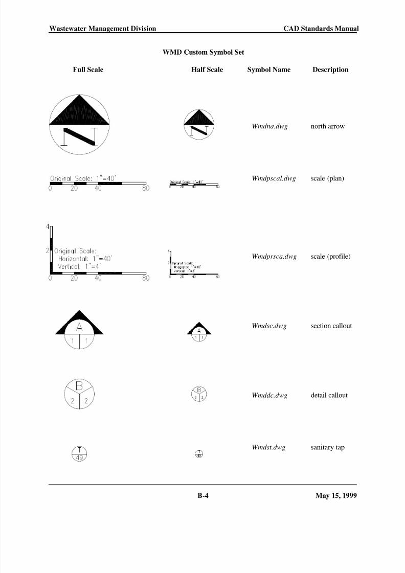
WMD Custom Symbol Set
Full Scale Half Scale Symbol Name Description
Wmdna.dwg north arrow
Wmdpscal.dwg scale (plan)
Wmdprsca.dwg scale (profile)
Wmdsc.dwg section callout
Wmddc.dwg detail callout
Wmdst.dwg sanitary tap

8/14/2019 CAD ESTANDARS
http://slidepdf.com/reader/full/cad-estandars 31/38
Wastewater Management Division CAD Standards Manual
C-1 May 15, 1999
Wmd Custom Text Styles
8/14/2019 CAD ESTANDARS
http://slidepdf.com/reader/full/cad-estandars 32/38
Wastewater Management Division CAD Standards Manual
C-2 May 15, 1999
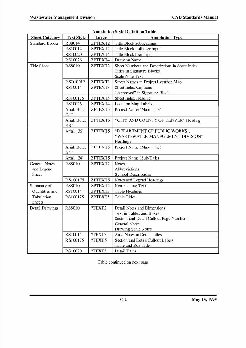
Annotation Style Definition Table
Sheet Category Text Style Layer Annotation Type
Standard Border RS8014 ZPTEXT2 Title Block subheadings
RS10014 ZPTEXT2 Title Block - all user input
RS10020 ZPTEXT4 Title Block headings
RS10026 ZPTEXT4 Drawing NameTitle Sheet RS8010 ZPTEXT2 Sheet Numbers and Descriptions in Sheet Index
Titles in Signature Blocks
Scale Note Text
RSO10012 ZPTEXT3 Street Names in Project Location Map
RS10014 ZPTEXT3 Sheet Index Captions
“Approved” in Signature Blocks
RS100175 ZPTEXT5 Sheet Index Heading
RS10026 ZPTEXT4 Location Map Labels
Arial, Bold,
.24”
ZPTEXT5 Project Name (Main Title)
Arial, Bold,.48” ZPTEXT5 “CITY AND COUNTY OF DENVER” Heading
Arial, .36” ZPTEXT5 “DEPARTMENT OF PUBLIC WORKS”,
“WASTEWATER MANAGEMENT DIVISION”
Headings
Arial, Bold,
.24”
ZPTEXT5 Project Name (Main Title)
Arial, .24” ZPTEXT5 Project Name (Sub-Title)
General Notes RS8010 ZPTEXT2 Notes
and Legend Abbreviations
Sheet Symbol Descriptions
RS100175 ZPTEXT5 Notes and Legend Headings
Summary of RS8010 ZPTEXT2 Non-heading Text
Quantities and RS10014 ZPTEXT3 Table Headings
Tabulation RS100175 ZPTEXT5 Table Titles
Sheets
Detail Drawings RS8010 ?TEXT2 Detail Notes and Dimensions
Text in Tables and Boxes
Section and Detail Callout Page Numbers
General Notes
Drawing Scale Notes
RS10014 ?TEXT3 Aux. Notes in Detail Titles
RS100175 ?TEXT5 Section and Detail Callout Labels
Table and Box Titles
RS10020 ?TEXT5 Detail Titles
Table continued on next page

8/14/2019 CAD ESTANDARS
http://slidepdf.com/reader/full/cad-estandars 33/38
Wastewater Management Division CAD Standards Manual
C-3 May 15, 1999
Annotation Style Definition Table (cont.)
Sheet Category Text Style Layer Annotation Type
Plan and Profile RS8010 ?TEXT2 General Notes
R.O.W. & Property Line Dimensions
Entity Notes and LabelingUtility Line Text
Invert Elevation Labels
“Boxed” Construction Notes
Sanitary Tap Labels
Section and Detail Callout Page Numbers
Scale Bar Text
Test Hole Materials in Profile
Connector Pipe Labels in Profile
Ground Line Labels in Profile
Elevation Labels in Profile
Property Line Labels in Profile
Manhole and Inlet Label Aux. Notes in ProfileRS8010 ?TEXT4 General Note Headings
Existing Ground Elevations in Profile
RSO8010 ?TEXT2 Rangeline, Section Line Labels and Dimensions
RS10010 ?TEXT2 Utility Line Dimension from Property Line
RSO10012 ?TEXT3 Existing Storm, Sanitary Labels
HGL Labels
Flow (Q) Labels
RS10014 ?TEXT4 Test Hole Labels
Stations in Manhole Labels
Inlet Labels
Storm, Sanitary Line Dimensions from Property LineMatch Line Notes
Profile Grid Elevation Labels
Profile Grid Station Labels
RS100175 ?TEXT5 Manhole Labels
Benchmark Labels
Match Line Labels and Stationing
Section and Detail Callout Labels
RSO100175 ?TEXT5 Street Name Labels
Pipe Run Labels in Profile
RD10026 ZPTEXT5 Plan, Profile Title Labels

8/14/2019 CAD ESTANDARS
http://slidepdf.com/reader/full/cad-estandars 34/38
Wastewater Management Division CAD Standards Manual
D-1 May 15, 1999
Wmd Land Development Desktop Description Keys
LDD
Desc. Key
Point Layer Symbol Symbol Layer LDD
Desc.
Description
ABS* SSTORM_SEW * ABS Pipe Invert
ABUT* SSTRUCTURE * Abutment
ASP* SROADWAY * Asphalt
BARK* SLANDSCAPING * Landscape Bark
BD3* SSIGNING WMDSIGN2 ESIGNING * Barricade Type III
BD4* SSIGNING WMDSIGN2 ESIGNING * Barricade Type IV
BENCH* SMISC WMDBENCH EMISC * Bus Bench
BLD* SBUILDING * Building
BM* SMONUMENT WMDBM EMONUMENT * Benchmark
BOL* SMISC WMDPOST EMISC * Bollard
BORDER* SLANDSCAPING * Landscape Border
BRICK* SSTRUCTURE * Brick Pavers
BRWLK* SSIDEWALK * Bridge Deck
BS* SSURVEY WMDSV ESURVEY * Back Sight
BWA* SSIDEWALK * Bikeway - Asphalt
BWC* SSIDEWALK * Bikeway - Concrete
BWF* SFENCE * Barbed Wire Fence
CATV* STELEVISION * Cable TV
CB1* SSTORM_SEW WMDET16 ESTORM_SEW * Inlet Type 16 (Single)
CB2* SSTORM_SEW WMDET16 ESTORM_SEW * Inlet Type 16 (Double)
CB3* SSTORM_SEW WMDET16 ESTORM_SEW * Inlet Type 16 (Triple)
CB4* SSTORM_SEW WMDET16 ESTORM_SEW * Inlet Type 16 (Quad.)
CBB* SSTORM_SEW WMDET16 ESTORM_SEW * Inlet (Bridge)
CBR* SSTORM_SEW WMDET14 ESTORM_SEW * Inlet Type 14
CBS* SSTORM_SEW WMDET16 ESTORM_SEW * Inlet (Special)
CBV1* SSTORM_SEW WMDET16 ESTORM_SEW * Valley Inlet (Single)
CBV2* SSTORM_SEW WMDET16 ESTORM_SEW * Valley Inlet (Double)
CBV3* SSTORM_SEW WMDET16 ESTORM_SEW * Valley Inlet (Triple)
CBV4* SSTORM_SEW WMDET16 ESTORM_SEW * Valley Inlet (Quad.)
CC* SROADWAY * Concrete
CHD* STOP_CURB * Concrete Curb Head
CHW* SSTRUCTURE * Concrete Headwall
CHX* SMONUMENT WMDCHX EMONUMENT * Chiseled “X”
CIP* SMISC WMDPOST EMISC * Cast Iron Pipe
CL SROADWAY * Roadway Centerline
CLF* SFENCE * Chain Link Fence
CMP* SSTORM_SEW * Corrugated Metal Pipe
COL* SSTRUCTURE * Column
CR* SCURB_RAMP * Curb Ramp
CS* SLANDSCAPING WMDCSHRB ELANDSCAPING * Coniferous Shrub
CT* SLANDSCAPING WMDCTREE ELANDSCAPING * Coniferous Tree
DEL* SSIGNING WMDSIGN1 ESIGNING * Delineator
DOCK* SBUILDING * Loading Dock
DOOR* SBUILDING * Door
DRT* SGROUND * Dirt
DS* SLANDSCAPING WMDDSHRB ELANDSCAPING * Deciduous Shrub

8/14/2019 CAD ESTANDARS
http://slidepdf.com/reader/full/cad-estandars 35/38
Wastewater Management Division CAD Standards Manual
D-2 May 15, 1999
Wmd Land Development Desktop Description Keys (cont.)
LDD
Desc. Key
Point Layer Symbol Symbol Layer LDD
Desc.
Description
DT* SLANDSCAPING WMDDTREE ELANDSCAPING * Deciduous Tree
DUMP* SMISC WMDDUMP EMISC * Trash Dumpster
DWY* SDRIVEWAY * Concrete Driveway
EBOX* SELECTRIC WMDTCBOX EELECTRIC * Electric Cabinet
EC* SROADWAY * Edge of Concrete
EP* SROADWAY * Edge of Pavement
EW* SWATER * Edge of Water Feature
FES* SSTORM_SEW * Flared End Section
FH* SWATER_UTIL WMDFH EWATER_UTIL * Fire Hydrant
FL SFLOWLINE * Flowline
FL# SFLOWLINE * Flowline (string)
FL## SFLOWLINE * Flowline (string)
FLR* SBUILDING * Building or Foundation Floor
FOU* SMISC WMDBOX EMISC * Water Fountain
FS SSURVEY WMDSV ESURVEY * Fore Sight
FSC* STOP_CURB * Flagstone Curb
FSW* SSIDEWALK * Flagstone Walk
GRL* SGUARDRAIL * Guardrail
GL* SGAS * Gas Line
GM* SGAS WMDWV EGAS * Gas Meter
GND* SGROUND * Ground
GP* SMISC WMDPOST EMISC * Guard Post
GRS* SLANDSCAPING * Grass
GRV* SGROUND * Gravel
GT* SFENCE * Gate
GUY* SELECTRIC WMDGUY EELECTRIC * Guy Wire
GV* SGAS WMDWV EGAS * Gas Valve
H&T* SSURVEY WMDSV ESURVEY * Hub and Tack
HDG* SLANDSCAPING WMDDSHRB ELANDSCAPING * Hedge
HERCP* SSTORM_SEW * HERCP Pipe Invert
HDW* SSTRUCTURE * Headwall
HR* SSTRUCTURE * Hand Rail
INV* SMISC * Invert
IP* SMONUMENT WMDREBAR EMONUMENT * Iron Pipe
LC* SMONUMENT WMDLC EMONUMENT * Land Corner
LIP* SLIP * Curb & Gutter Lip
LP* SELECTRIC WMDSL EELECTRIC * Street Light Pole
LR* SLANDSCAPING * Landscape Rock
MBX* SMISC WMDMAIL EMISC * Mailbox
MHU* SMISC_UTIL WMDEMH EMISC_UTIL * Manhole - Unknown
MHE* SELECTRIC WMDEMH EELECTRIC * Manhole - Electric
MHN* SSANITARY WMDEMH ESANITARY * Manhole - Sanitary
MHS* SSTORM_SEW WMDEMH ESTORM_SEW * Manhole - Storm
MHT* STELEPHONE WMDEMH ETELEPHONE * Manhole - Telephone
MHW* SWATER_UTIL WMDEMH EWATER_UTIL * Manhole - Water Utility
MON* SMONUMENT WMDSV EMONUMENT * Monument (misc.)
NBX* SMISC WMDNEWS EMISC * News Box

8/14/2019 CAD ESTANDARS
http://slidepdf.com/reader/full/cad-estandars 36/38
Wastewater Management Division CAD Standards Manual
D-3 May 15, 1999
Wmd Land Development Desktop Description Keys (cont.)
LDD
Desc. Key
Point Layer Symbol Symbol Layer LDD
Desc.
Description
P&C* SMONUMENT WMDPC EMONUMENT * Pin and Cap
PBE* SELECTRIC WMDPBE EELECTRIC * Pull Box - Electric
PBTEL* STELEPHONE WMDPBT ETELEPHONE * Pull Box - Telephone
PBTRAF* STRAF_SGNL WMDPBT ETRAF_SGNL * Pull Box - Traffic
PIER* SSTRUCTURE * Pier
PIP* SMISC WMDPOST EMISC * Pipe
PK* SMONUMENT WMDSV EMONUMENT * PK Nail
PLTR* SLANDSCAPING * Planter
PM* SMISC WMDPOST EMISC * Parking Meter
PP* SELECTRIC WMDPP EELECTRIC * Power Pole
PRK* SMISC * Parking Lot
PVC* SSTORM_SEW * PVC Pipe Invert
RBOX* SMONUMENT WMDRP EMONUMENT * Range Box
REBAR* SMONUMENT WMDREBAR EMONUMENT * Rebar
RCB* SSTORM_SEW * Reinforced Concrete Box
RCP* SSTORM_SEW * Reinforced Concrete Pipe
RD* SSTORM_SEW WMDPOST ESTORM_SEW * Roof Drain
RIP* SGROUND * Rip Rap
RP* SMONUMENT WMDRP EMONUMENT * Range Point
RRP* SRAILROAD * Railroad Crossing Pad
RRS* SSIGNING WMDSIGN1 ESIGNING * Railroad Crossing Sign
RRT* SRAILROAD * Railroad Track
RTW* SSTRUCTURE * Retaining Wall
SAN* SSANITARY * Sanitary Sewer
SIGN* SSIGNING WMDSIGN1 ESIGNING * Sign
SPC* SSPRINKLER WMDWV ESPRINKLER * Sprinkler Controller
SPH* SSPRINKLER WMDWV ESPRINKLER * Sprinkler Head
SPV* SSPRINKLER WMDWV ESPRINKLER * Sprinkler Valve
STM* SSTORM_SEW * Storm Sewer
STEP* SMISC * Step
SW* SSTRUCTURE * Stone Wall
TBM* SMONUMENT WMDBM EMONUMENT * Temporary Benchmark
TC* STOP_CURB * Top of Curb
TELBOX* STELEPHONE WMDTCBOX STELEPHONE * Telephone Cabinet
TRAFBOX* STRAF_SGNL WMDTCBOX STRAF_SGNL * Traffic Signal Control Box
TOE SGROUND * Toe of Slope
TOE# SGROUND * Toe of Slope (string)
TOP SGROUND * Top of Slope
TOP# SGROUND * Top of Slope (string)
TOS* SMISC * Top of Step
TOW* SSTRUCTURE * Top of Wall
TRASH* SMISC WMDTRASH EMISC * Trash Container
TRS* SLANDSCAPING WMDSTUMP ELANDSCAPING * Tree Stump
TSG* STRAF_SGNL WMDTL ETRAF_SGNL * Traffic Signal Pole
TSN* SSIGNING WMDSIGN1 ESIGNING * Traffic Sign
TVP* SSURVEY WMDSV ESURVEY * Traverse Point
TWL* SLANDSCAPING * Tree Well
8/14/2019 CAD ESTANDARS
http://slidepdf.com/reader/full/cad-estandars 37/38
Wastewater Management Division CAD Standards Manual
D-4 May 15, 1999
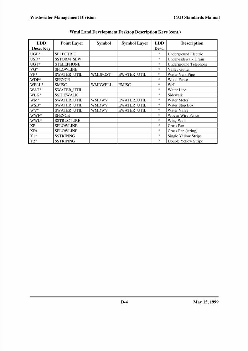
Wmd Land Development Desktop Description Keys (cont.)
LDD
Desc. Key
Point Layer Symbol Symbol Layer LDD
Desc.
Description
UGE* SELECTRIC * Underground Electric
USD* SSTORM_SEW * Under-sidewalk Drain
UGT* STELEPHONE * Underground Telephone
VG* SFLOWLINE * Valley Gutter
VP* SWATER_UTIL WMDPOST EWATER_UTIL * Water Vent Pipe
WDF* SFENCE * Wood Fence
WELL* SMISC WMDWELL EMISC * Well
WAT* SWATER_UTIL * Water Line
WLK* SSIDEWALK * Sidewalk
WM* SWATER_UTIL WMDWV EWATER_UTIL * Water Meter
WSB* SWATER_UTIL WMDWV EWATER_UTIL * Water Stop Box
WV* SWATER_UTIL WMDWV EWATER_UTIL * Water Valve
WWF* SFENCE * Woven Wire Fence
WWL* SSTRUCTURE * Wing Wall
XP SFLOWLINE * Cross Pan
XP# SFLOWLINE * Cross Pan (string)
Y1* SSTRIPING * Single Yellow Stripe
Y2* SSTRIPING * Double Yellow Stripe

8/14/2019 CAD ESTANDARS
http://slidepdf.com/reader/full/cad-estandars 38/38
Wastewater Management Division CAD Standards Manual
WMD.LIN
WMD Custom Linetype File
;; WMD.LIN AutoCAD Linetype file
;; Created 2/4/98 by Dan Roberts
;; Defines WMD Custom Linetypes
;;*Rangeline,____________ _ _ ____________A,.95,-.033,.033,-.033,.033,-.033
*TELEPHONE,-------
A,.25,-.075*TELEVISION,-------
A,.25,-.075*ELECTRIC,-------
A,.25,-.075*GAS,-------
A,.1875,-.0755
*STEAM,-------A,.1875,-.075
*WATER,-------A,.5,-.075
*STORM,-------
A,.375,-.075*SANITARY,-------
A,.5,-.075