cad-earth user manual - bricscad · imported from google earth to major cad programs (autocad,...
TRANSCRIPT
Copyright © 2013 CADSite Software Google Earth© is a registered trademark of Google Inc. All other trademarks are the property of their respective owners.
http://www.cad-earth.com
CAD-Earth User’s Manual
Copyright © 2013 CADSite Software Google Earth© is a registered trademark of Google Inc. All other trademarks are the property of their respective owners.
http://www.cad-earth.com
Table of Contents
Introduction .............................................................................................................................. 2
CAD-Earth commands
Import image from Google Earth ............................................................................................ 4 Export CAD screenshot to Google Earth .................................................................................. 7 Import objects from Google Earth .......................................................................................... 10 Export CAD object to Google Earth ......................................................................................... 16 Make point blocks ................................................................................................................. 21 Import terrain mesh from Google Earth .................................................................................. 22 Contour lines ........................................................................................................................ 26 Set mesh visibility ................................................................................................................. 29 Draw cross sections from mesh .............................................................................................. 30 Annotate cross sections ......................................................................................................... 40 Draw profile from mesh ......................................................................................................... 42 Annotate profile .................................................................................................................... 52 Slope analysis ....................................................................................................................... 54 License Manager ................................................................................................................... 57 License Activation Center ....................................................................................................... 59 Contacting Technical Support ................................................................................................. 61
Frequently Asked Questions (F.A.Q.) .......................................................................................... 62

Copyright © 2013 CADSite Software Google Earth© is a registered trademark of Google Inc. All other trademarks are the property of their respective owners.
http://www.cad-earth.com
Navigation: CAD-EarthIntroduion
With CAD-Earth you can easily Import/export images, objects and terrain configurations between Google
Earth and major CAD programs.
What can I do with CAD-Earth?
Import images from Google Earth. Images can be imported to CAD programs in full color or
grayscale in major image formats (BMP, JPEG, TIFF). Images can be clipped inside a closed
polyline and tiled images can be created to increase image resolution.
Import Google Earth objects to CAD programs. Polygons, routes and placemarks can be
imported from Google Earth to major CAD programs (AutoCAD, Civil3D, ZWCAD+, Bricscad Pro).
Polygons can be imported as 2D or 3D polylines projected to terrain, optionally applying fill color.
Placemarks can be imported as blocks with elevation, including placemark name and description. A
symbol library is included where you can select the placemark block to be inserted or you can add
your own blocks.
Export CAD objects to Google Earth. Lines, polylines, arc, circles, points can be exported to
Google Earth as polygons, routes or placemarks. Object line thickness, outline, fill color and
opacity can be adjusted. Curve smoothness can be controlled specifying the maximum segment
length and deflection angle. Placemark name, description, scale and icon can also be set.
Export CAD screenshots to Google Earth. CAD drawings can be exported to Google Earth as
image overlays. Image capture can be in full color, grayscale or B&W in major image formats
(BMP, JPEG, TIFF, PNG, GIF). Background color can be completely transparent or changed to
another color if desired. Screenshots can be also taken in sections to increase final image
resolution.
Get contour lines, profiles and sections from Google Earth (Plus version). A terrain
configuration mesh can be created inside an existing closed polyline or along a polyline path
calculating point elevations from Google Earth. Specifying the origin point, rotation angle and
distance between rows and columns the mesh density and precision can be adjusted. The resulting
mesh can be processed to obtain contour lines, dynamic profile and section drawings complete
with annotations.

Copyright © 2013 CADSite Software Google Earth© is a registered trademark of Google Inc. All other trademarks are the property of their respective owners.
http://www.cad-earth.com
What are the benefits of using CAD-Earth?
Easy to use commands. You can pick CAD-Earth commands from a toolbar, from the screen
menu or at the command prompt. Automatic load of commands in each CAD session and extensive
help in each step.
Persistent dialog box settings. Once you set options in a dialog box, they are automatically
saved so you don't have to set them each time you use a CAD-Earth command.
Dynamic object updating. When you modify object settings the corresponding contour lines,
profiles or sections are dynamically updated reflecting the new changes.
Flexible licensing and pricing. You can use the same license in multiple CAD/Windows platforms
(AutoCAD Full, Civil 3D, ZWCAD+, BricsCAD Pro). CAD-Earth can be purchased as a permanent or
one year license in Basic or Plus versions. Registered users can manage licenses via web in the
CAD-Earth Activation Center to be able to generate and transfer licenses.
Works with all Google Earth versions and multiple CAD/Windows platforms. Can be used
with Google Earth free and Pro versions and in major CAD platforms (AutoCAD Full / Civil3D 2007-
2013, ZWCAD+ 2012, BricsCAD v13 Pro) in Windows XP, Vista, 7 and 8 in 32 or 64 bits.
Automatic Google Earth startup and object location. When you export objects, screenshots or
import a terrain configuration Google Earth will be automatically activated to show the exact
location where the objects are placed so you can be sure if your settings are right.
Uses inches or meters to perform calculations and annotations.
Free direct technical assistance by the programmers. You can request new features and
technical support directly to the programmers from the CAD-Earth menu.
Copyright © 2013 CADSite Software Google Earth© is a registered trademark of Google Inc. All other trademarks are the property of their respective owners.
http://www.cad-earth.com
Navigation: CAD-Earth commands >
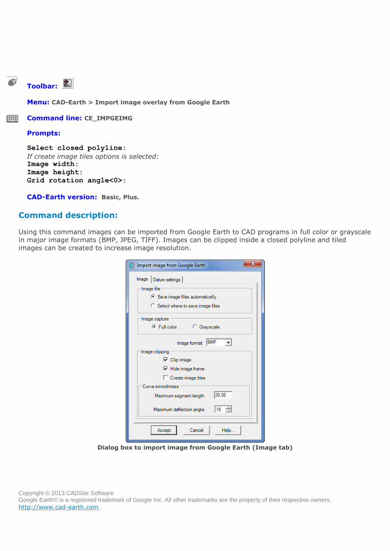
Import image from Google Earth
Toolbar:
Menu: CAD-Earth > Import image overlay from Google Earth
Command line: CE_IMPGEIMG
Prompts: Select closed polyline:
If create image tiles options is selected: Image width:
Image height:
Grid rotation angle<0>:
CAD-Earth version: Basic, Plus.
Command description:
Using this command images can be imported from Google Earth to CAD programs in full color or grayscale
in major image formats (BMP, JPEG, TIFF). Images can be clipped inside a closed polyline and tiled
images can be created to increase image resolution.
Dialog box to import image from Google Earth (Image tab)
Copyright © 2013 CADSite Software Google Earth© is a registered trademark of Google Inc. All other trademarks are the property of their respective owners.
http://www.cad-earth.com
Dialog box settings (Image tab):
Image file.
Save image files automatically. If you select this option image files will be saved in the
CAD-Earth Images folder automatically assigning a consecutive file name.
Select where to save image files. A file selection dialog box will be shown where you set
the file name and folder where the image will be saved.
Image capture. Image can be imported in full color or in grayscale.
Image format. Available image formats are: BMP, JPEG an TIFF. Use the JPEG format if you need
to reduce the imported image file size to the maximum possible.
Image clipping.
Clip image. Image will be clipped inside the closed polyline.
Hide image frame. If the image frame is not visible it will not be printed but the image
can't be selected. To turn on the image frame set the IMAGEFRAME variable to ON (1).
Create image tiles. Instead of just one image inside the closed polygon image tiles can be
inserted consecutively in rows, increasing the final image resolution and level of detail.
Curve smoothness. If the closed polyline has curved sides they will be converted to
straight segments before the image is clipped. The number of resulting segments will be
proportional to the maximum segment length and the maximum deflection angle between
consecutive segments specified. If the image will not be clipped or if the closed polyline
doesn't have curved segments this option will have no effect.
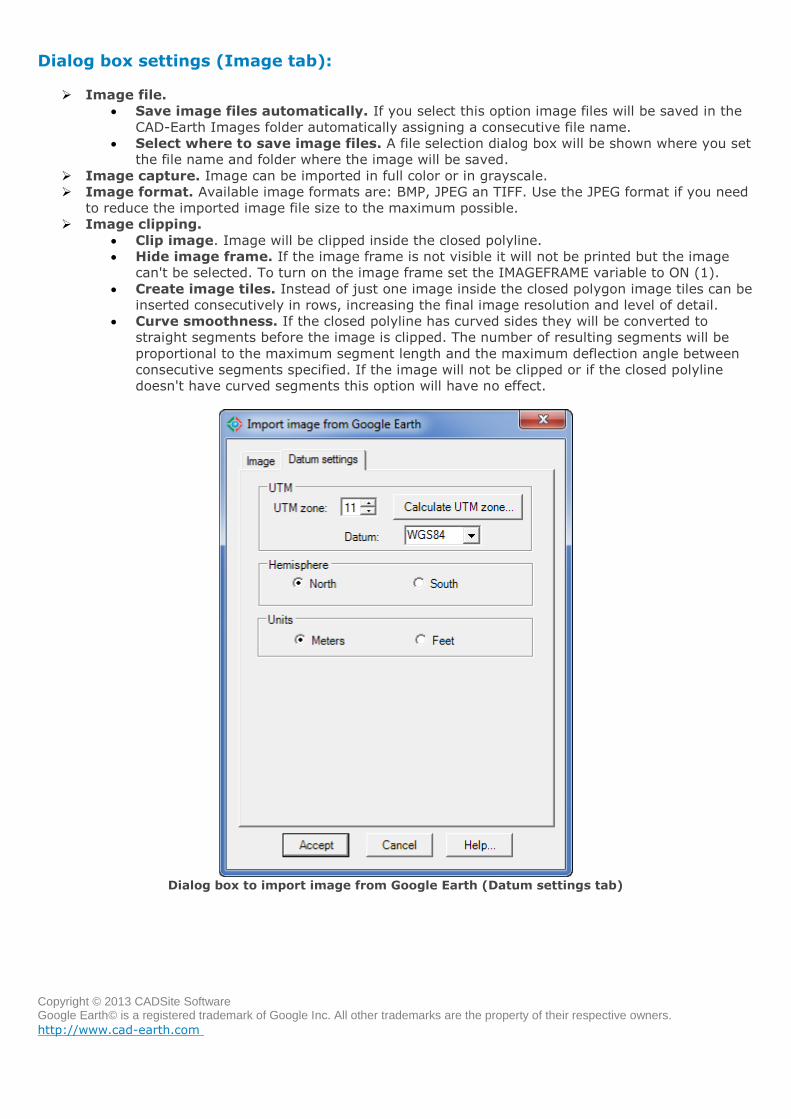
Dialog box to import image from Google Earth (Datum settings tab)
Copyright © 2013 CADSite Software Google Earth© is a registered trademark of Google Inc. All other trademarks are the property of their respective owners.
http://www.cad-earth.com
Dialog box settings (Datum settings tab):
UTM
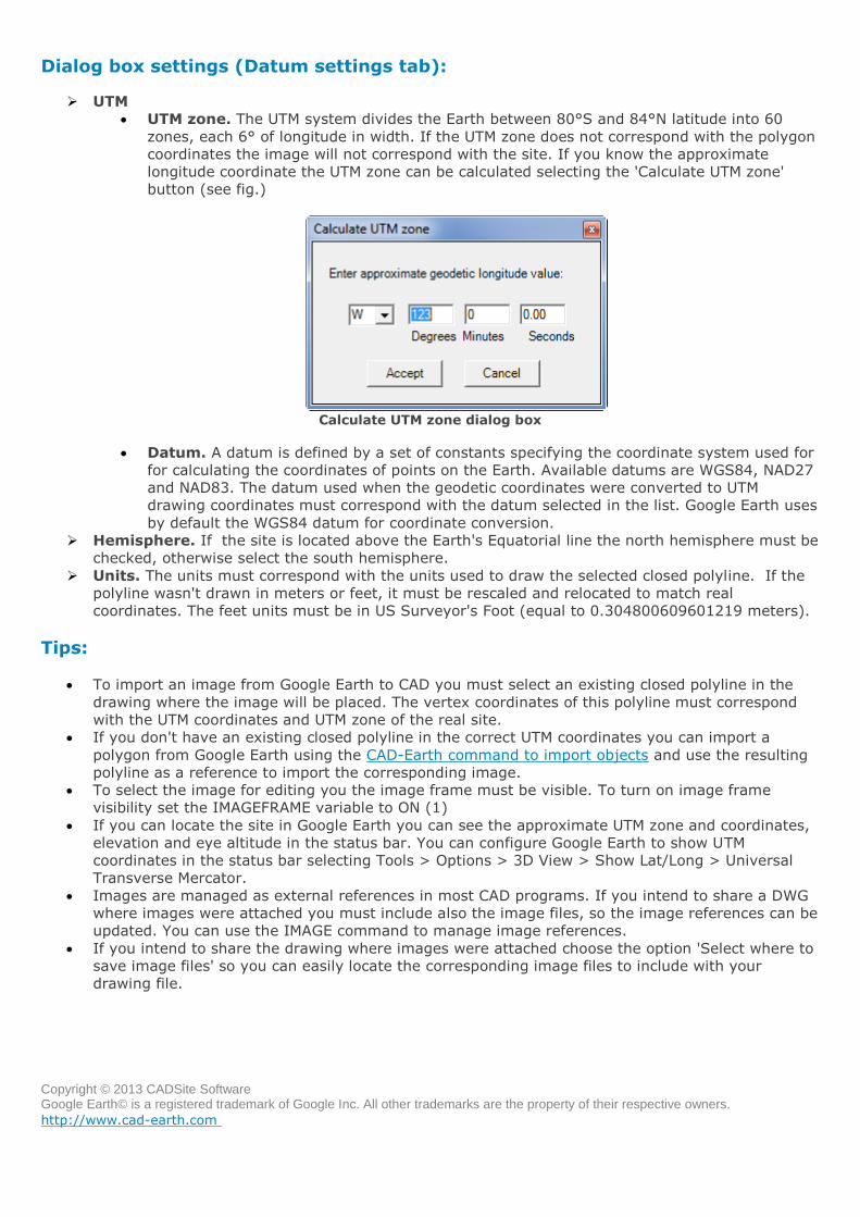
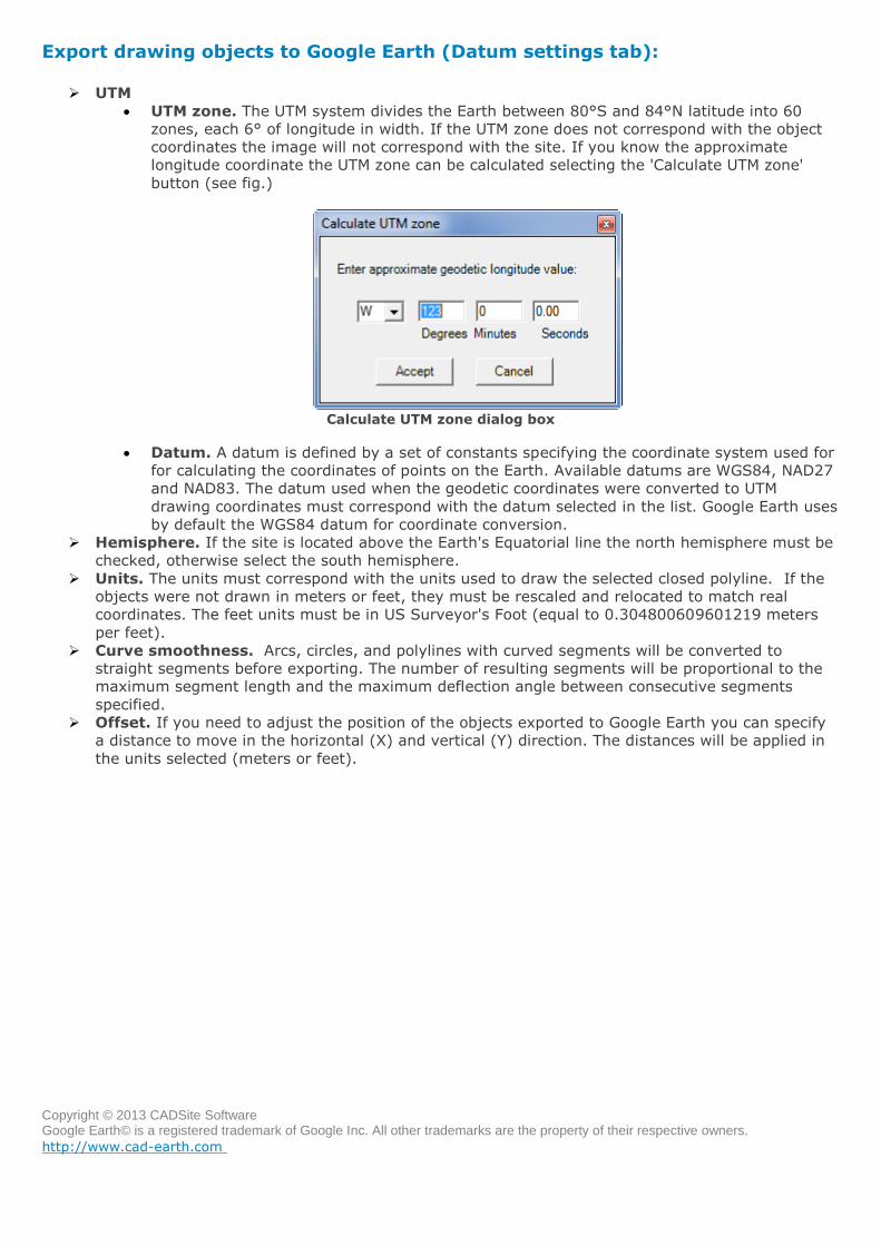
UTM zone. The UTM system divides the Earth between 80°S and 84°N latitude into 60
zones, each 6° of longitude in width. If the UTM zone does not correspond with the polygon
coordinates the image will not correspond with the site. If you know the approximate
longitude coordinate the UTM zone can be calculated selecting the 'Calculate UTM zone'
button (see fig.)
Calculate UTM zone dialog box
Datum. A datum is defined by a set of constants specifying the coordinate system used for
for calculating the coordinates of points on the Earth. Available datums are WGS84, NAD27
and NAD83. The datum used when the geodetic coordinates were converted to UTM
drawing coordinates must correspond with the datum selected in the list. Google Earth uses
by default the WGS84 datum for coordinate conversion.
Hemisphere. If the site is located above the Earth's Equatorial line the north hemisphere must be
checked, otherwise select the south hemisphere.
Units. The units must correspond with the units used to draw the selected closed polyline. If the
polyline wasn't drawn in meters or feet, it must be rescaled and relocated to match real
coordinates. The feet units must be in US Surveyor's Foot (equal to 0.304800609601219 meters).
Tips:
To import an image from Google Earth to CAD you must select an existing closed polyline in the
drawing where the image will be placed. The vertex coordinates of this polyline must correspond
with the UTM coordinates and UTM zone of the real site.
If you don't have an existing closed polyline in the correct UTM coordinates you can import a
polygon from Google Earth using the CAD-Earth command to import objects and use the resulting
polyline as a reference to import the corresponding image.
To select the image for editing you the image frame must be visible. To turn on image frame
visibility set the IMAGEFRAME variable to ON (1)
If you can locate the site in Google Earth you can see the approximate UTM zone and coordinates,
elevation and eye altitude in the status bar. You can configure Google Earth to show UTM
coordinates in the status bar selecting Tools > Options > 3D View > Show Lat/Long > Universal
Transverse Mercator.
Images are managed as external references in most CAD programs. If you intend to share a DWG
where images were attached you must include also the image files, so the image references can be
updated. You can use the IMAGE command to manage image references.
If you intend to share the drawing where images were attached choose the option 'Select where to
save image files' so you can easily locate the corresponding image files to include with your
drawing file.
Copyright © 2013 CADSite Software Google Earth© is a registered trademark of Google Inc. All other trademarks are the property of their respective owners.
http://www.cad-earth.com
Navigation: CAD-Earth commands >
Export CAD screenshot to Google Earth
Toolbar:
Menu: CAD-Earth > Export screen capture to Google Earth
Command line: CE_EXPGEIMG
Prompts:
Select screen capture window:
Press [ENTER] to continue...
If create tiled images options selected: Number of image rows:
Number of image columns:
CAD-Earth version: Basic, Plus.
Command description:
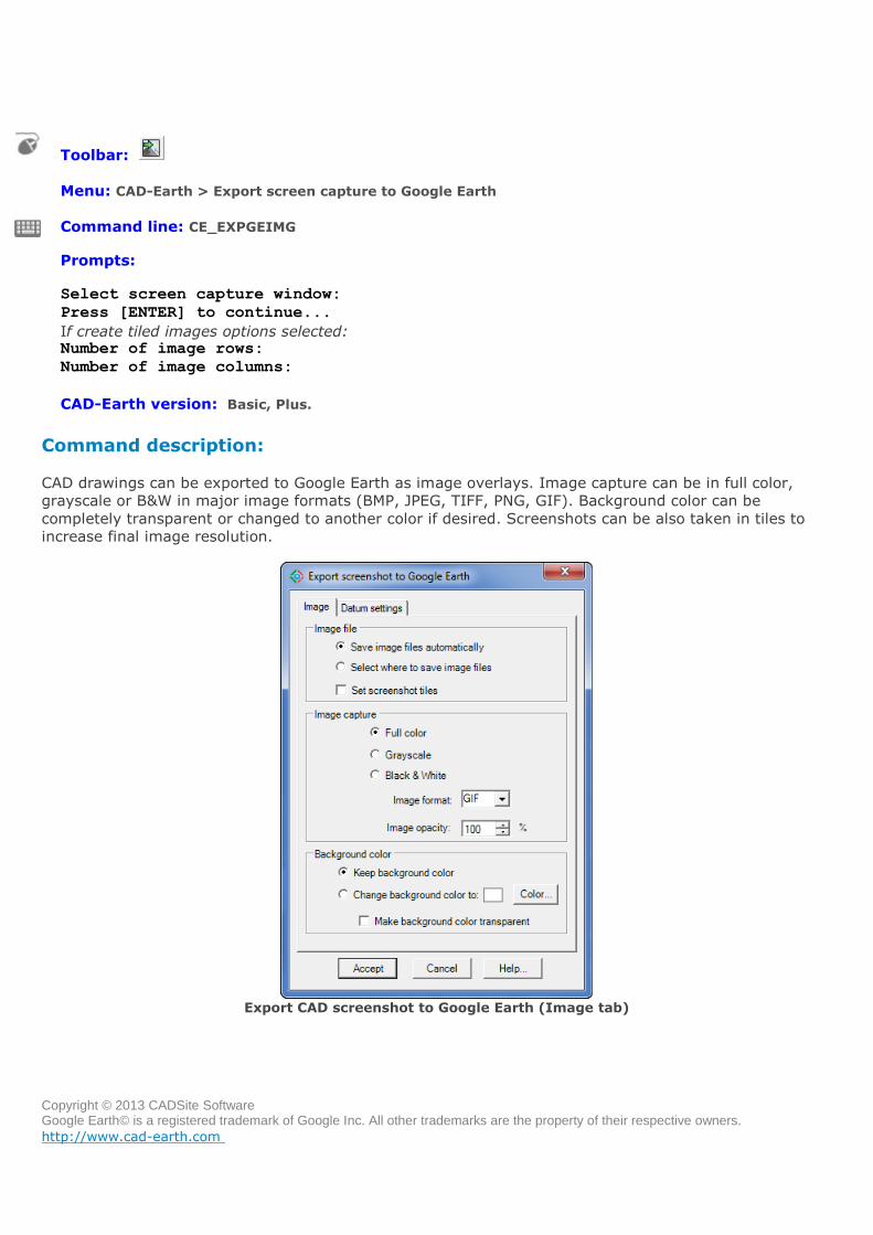
CAD drawings can be exported to Google Earth as image overlays. Image capture can be in full color,
grayscale or B&W in major image formats (BMP, JPEG, TIFF, PNG, GIF). Background color can be
completely transparent or changed to another color if desired. Screenshots can be also taken in tiles to
increase final image resolution.
Export CAD screenshot to Google Earth (Image tab)
Copyright © 2013 CADSite Software Google Earth© is a registered trademark of Google Inc. All other trademarks are the property of their respective owners.
http://www.cad-earth.com
Dialog box settings (Image tab):
Image file.
Save image files automatically. If you select this option image files will be saved in the
CAD-Earth Images folder automatically assigning a consecutive file name.
Select where to save image files. file selection dialog box will be shown where you set
the file name and folder where the image will be saved.
Set screenshot tiles. If this option is set, screenshots will be taken consecutively in rows.
Number of image rows and columns must be entered before the screenshots are taken.
Image capture.
Full color. Screenshot will be taken as seen in the CAD screen.
Grayscale. Screen colors will be converted to equivalent shades of gray.
Black & white. Screen colors will be converted to black and white.
Image format. Screenshots can be saved in the following formats: BMP, JPEG, TIFF, GIF,
PNG. If you intend to make the background color transparent you must select the PNG
format.
Image opacity. The overall image opacity can be set from 0% (completely invisible) to
100% (completely visible).
Background color.
Keep background color. Screenshots will be taken registering the actual drawing screen
background color.
Change background color. Drawing screen background color will be changed to the color
selected.
Make background color transparent. Drawing screen background color will be
completely transparent, only the drawing elements will be visible.
Copyright © 2013 CADSite Software Google Earth© is a registered trademark of Google Inc. All other trademarks are the property of their respective owners.
http://www.cad-earth.com
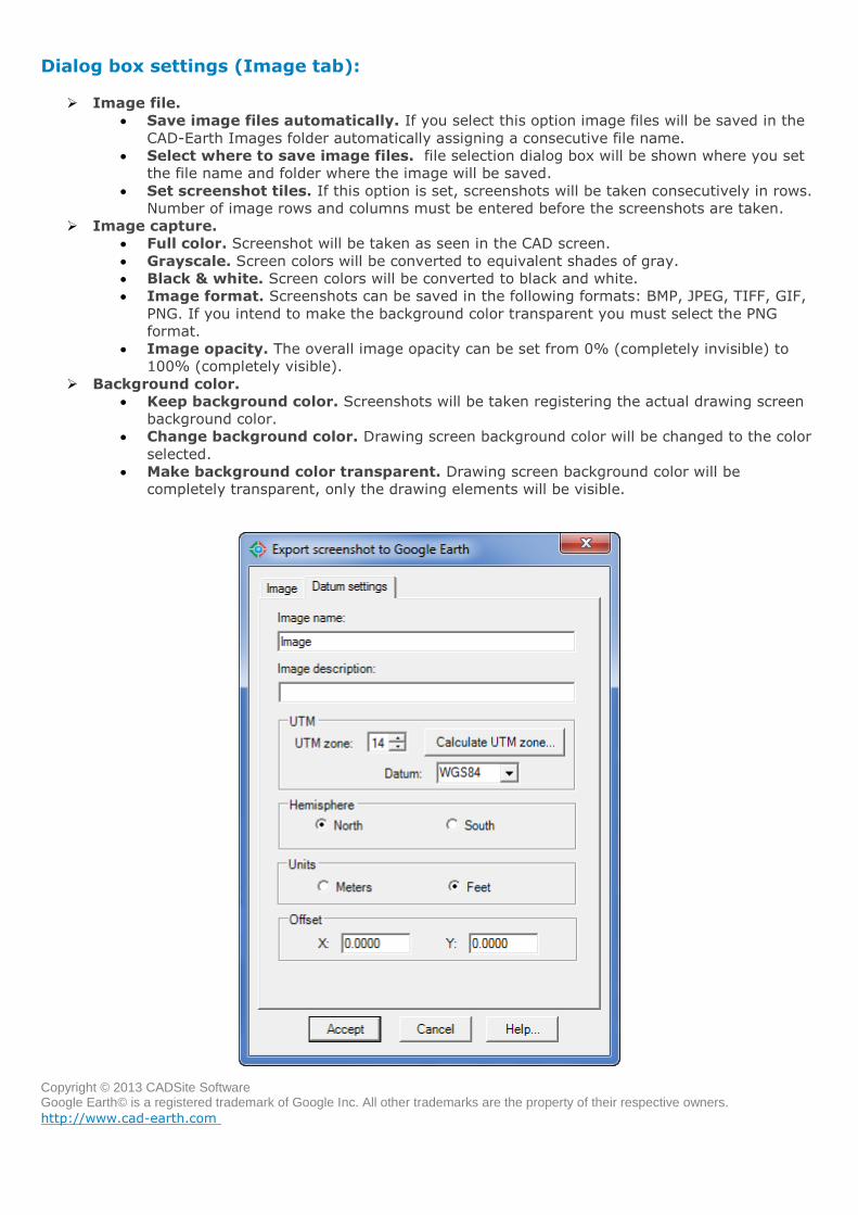
Export CAD screenshot to Google Earth (Datum settings tab)
Dialog box settings (Datum settings tab):
Image name and description. This information will be shown in Google Earth 'My Places'
explorer as the name and description of the corresponding image overlay node.
UTM
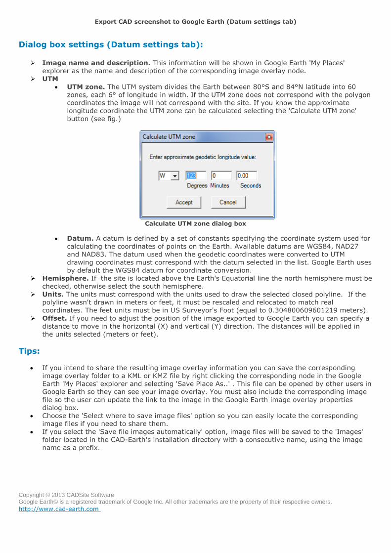
UTM zone. The UTM system divides the Earth between 80°S and 84°N latitude into 60
zones, each 6° of longitude in width. If the UTM zone does not correspond with the polygon
coordinates the image will not correspond with the site. If you know the approximate
longitude coordinate the UTM zone can be calculated selecting the 'Calculate UTM zone'
button (see fig.)
Calculate UTM zone dialog box
Datum. A datum is defined by a set of constants specifying the coordinate system used for
calculating the coordinates of points on the Earth. Available datums are WGS84, NAD27
and NAD83. The datum used when the geodetic coordinates were converted to UTM
drawing coordinates must correspond with the datum selected in the list. Google Earth uses
by default the WGS84 datum for coordinate conversion.
Hemisphere. If the site is located above the Earth's Equatorial line the north hemisphere must be
checked, otherwise select the south hemisphere.
Units. The units must correspond with the units used to draw the selected closed polyline. If the
polyline wasn't drawn in meters or feet, it must be rescaled and relocated to match real
coordinates. The feet units must be in US Surveyor's Foot (equal to 0.304800609601219 meters).
Offset. If you need to adjust the position of the image exported to Google Earth you can specify a
distance to move in the horizontal (X) and vertical (Y) direction. The distances will be applied in
the units selected (meters or feet).
Tips:
If you intend to share the resulting image overlay information you can save the corresponding
image overlay folder to a KML or KMZ file by right clicking the corresponding node in the Google
Earth 'My Places' explorer and selecting 'Save Place As..' . This file can be opened by other users in
Google Earth so they can see your image overlay. You must also include the corresponding image
file so the user can update the link to the image in the Google Earth image overlay properties
dialog box.
Choose the 'Select where to save image files' option so you can easily locate the corresponding
image files if you need to share them.
If you select the 'Save file images automatically' option, image files will be saved to the 'Images'
folder located in the CAD-Earth's installation directory with a consecutive name, using the image
name as a prefix.
Copyright © 2013 CADSite Software Google Earth© is a registered trademark of Google Inc. All other trademarks are the property of their respective owners.
http://www.cad-earth.com
Navigation: CAD-Earth commands >
Import objects from Google Earth
Toolbar:
Menu: CAD-Earth > Import objects from Google Earth
Command line: CE_IMPGEOBJ
CAD-Earth version: Basic, Plus.
Command description:
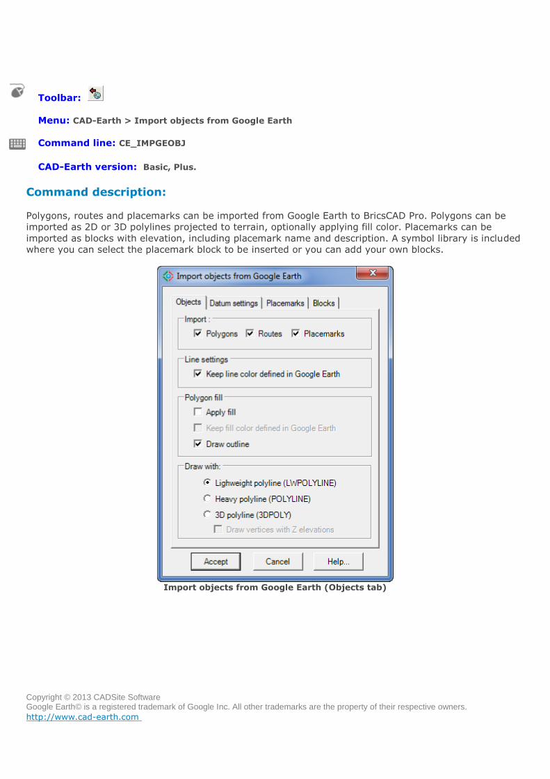
Polygons, routes and placemarks can be imported from Google Earth to BricsCAD Pro. Polygons can be
imported as 2D or 3D polylines projected to terrain, optionally applying fill color. Placemarks can be
imported as blocks with elevation, including placemark name and description. A symbol library is included
where you can select the placemark block to be inserted or you can add your own blocks.
Import objects from Google Earth (Objects tab)
Copyright © 2013 CADSite Software Google Earth© is a registered trademark of Google Inc. All other trademarks are the property of their respective owners.
http://www.cad-earth.com
Dialog box settings (Objects tab):
Import:
Polygons. Imported polygons from Google Earth to BricsCAD Pro will be drawn as closed
polylines.
Routes. Imported routes from Google Earth to BricsCAD Pro will be drawn as open
polylines.
Placemarks. Imported placemarks from Google Earth to BricsCAD Pro will be drawn as
points and block inserts.
Line settings
Keep line color defined in Google Earth. If you deselect this option objects will be
imported to BricsCAD Pro and drawn using the current color.
Polygon fill:
Apply fill. A solid hatch will be applied to polygons when imported to BricsCAD Pro.
Keep color defined in Google Earth. If you deselect this option a solid hatch using the
current color will be applied to polygons when imported, otherwise the fill color they had in
Google Earth will be used.
Draw outline. If hatching will be applied to the imported polygons, you can choose not to
draw their outline.
Draw with:
Lightweight polyline. Imported polygons and routes will be drawn with regular polylines
in BricsCAD Pro.
Heavy polyline. Imported polygons and routes will be drawn with heavy polylines in
BricsCAD Pro.
3D polyline. Imported polygons and routes will be drawn with 3D polylines in BricsCAD
Pro, which can have different Z elevations in each vertex.
Draw vertices with Z elevations. Elevation in each vertex will be calculated to draw
imported objects with 3D polylines.
Copyright © 2013 CADSite Software Google Earth© is a registered trademark of Google Inc. All other trademarks are the property of their respective owners.
http://www.cad-earth.com
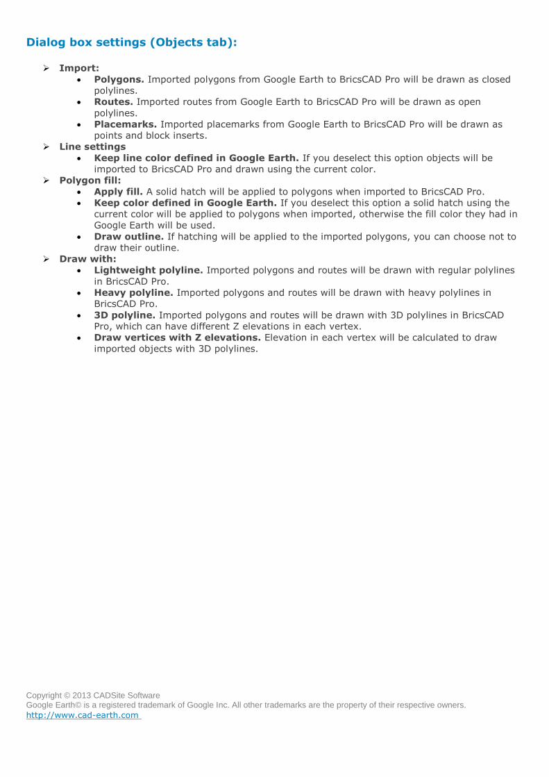
Import objects from Google Earth (Datum settings tab)
Dialog box settings (Datum settings tab):
Read data.
From Google Earth default KML file. Data will be read from the 'myplaces.kml' Google
Earth file.
Select KML file. Data will be read from a KML file selected by the user.
Units.
Meters. No conversion will be applied to data read from the KML file.
Feet. Coordinates and distances will be converted from meters to feet (1 meter equal to
0.304800609601219 US Surveyor's foot)
UTM.
Datum. Available datums are WGS84, NAD27 and NAD83. The datum used when the
geodetic coordinates were converted to UTM drawing coordinates must correspond with the
datum selected in the list. Google Earth uses by default the WGS84 datum for coordinate
conversion.
Copyright © 2013 CADSite Software Google Earth© is a registered trademark of Google Inc. All other trademarks are the property of their respective owners.
http://www.cad-earth.com
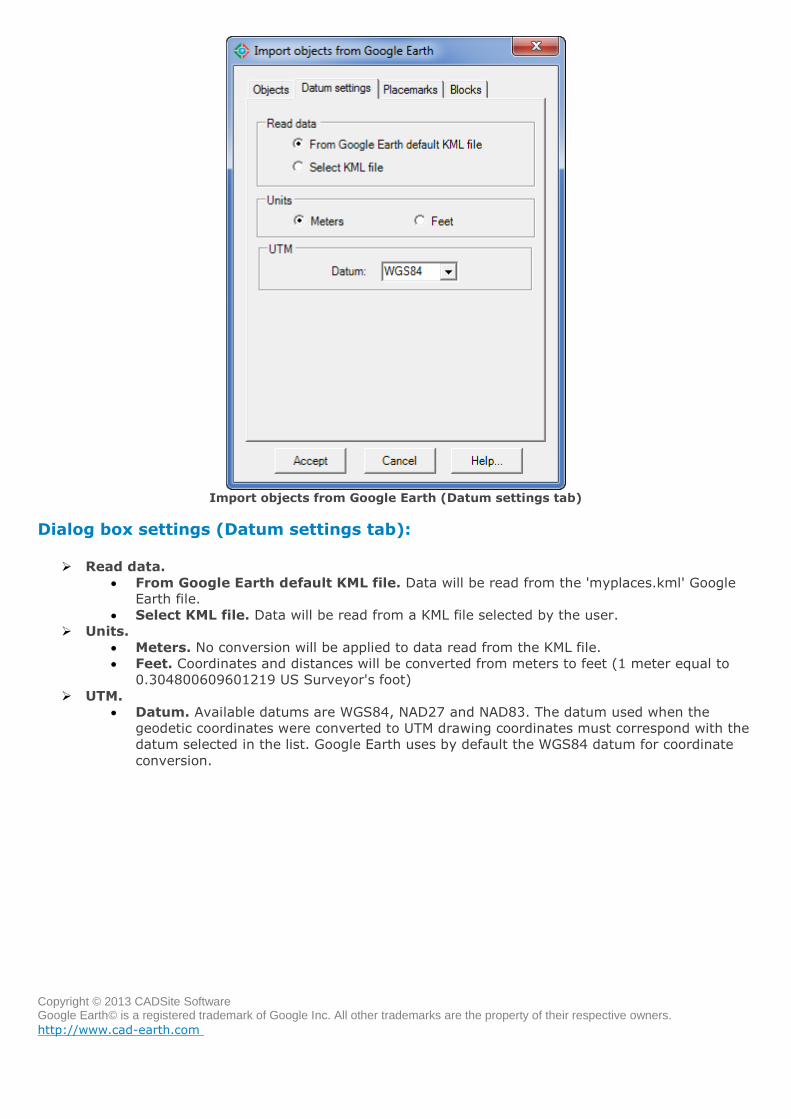
Import objects from Google Earth (Placemarks tab)
Dialog box settings (Placemarks tab):
Elevation:
Projected to terrain. Elevation will be calculated to be on the ground in the placemark's
XY position.
Placemark elevation. Elevation will be the same as the placemark elevation in Google
Earth.
Zero. Elevation will be at sea level (absolute zero)
Annotations:
Text size. Set placemark's name and description text size in drawing units.
Text color. Select color for placemark's name and description text.
Text layer. Select layer for placemark's name and description text.
Text style. Select text style for placemark's name and description.
Annotate name. Select to write placemark's name in drawing.
Annotate description. Select to write placemark's description in drawing.
Copyright © 2013 CADSite Software Google Earth© is a registered trademark of Google Inc. All other trademarks are the property of their respective owners.
http://www.cad-earth.com
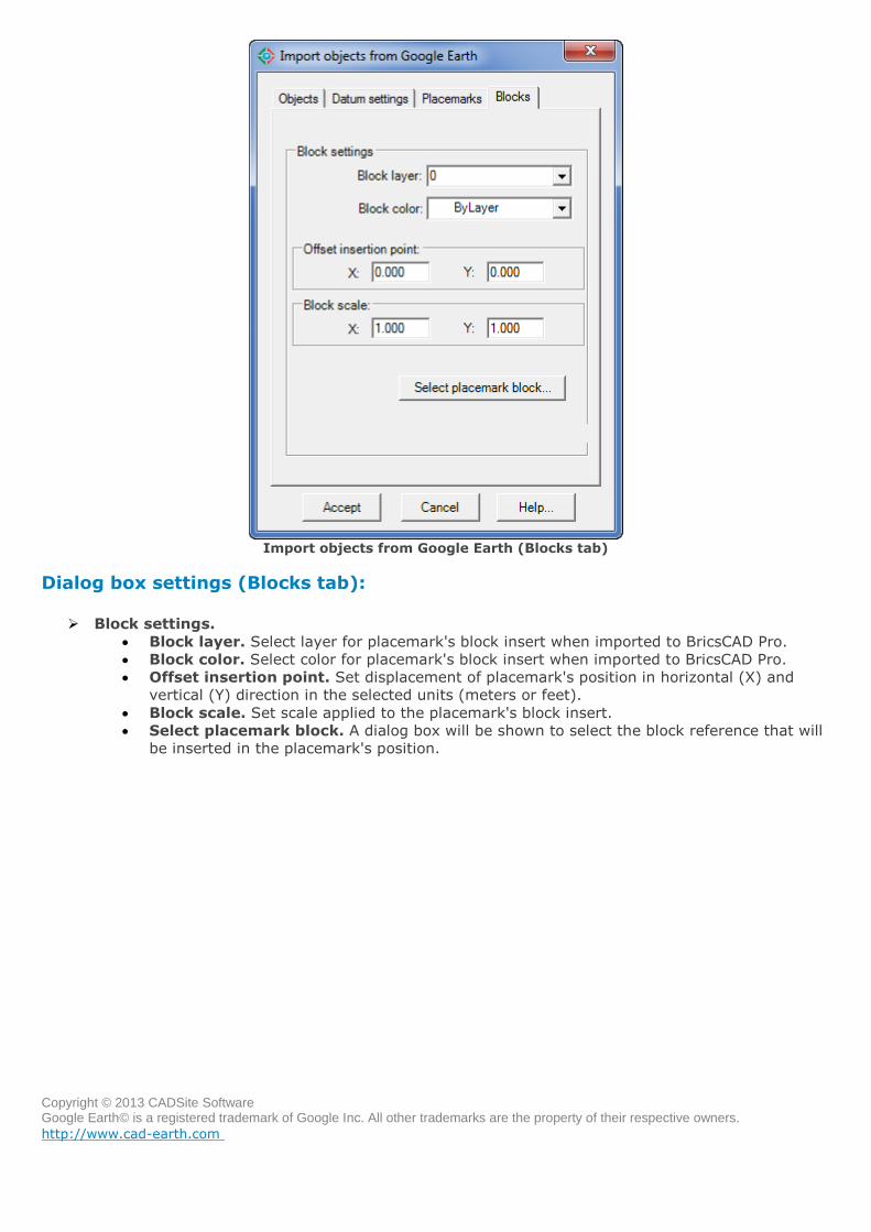
Import objects from Google Earth (Blocks tab)
Dialog box settings (Blocks tab):
Block settings.
Block layer. Select layer for placemark's block insert when imported to BricsCAD Pro.
Block color. Select color for placemark's block insert when imported to BricsCAD Pro.
Offset insertion point. Set displacement of placemark's position in horizontal (X) and
vertical (Y) direction in the selected units (meters or feet).
Block scale. Set scale applied to the placemark's block insert.
Select placemark block. A dialog box will be shown to select the block reference that will
be inserted in the placemark's position.
Copyright © 2013 CADSite Software Google Earth© is a registered trademark of Google Inc. All other trademarks are the property of their respective owners.
http://www.cad-earth.com
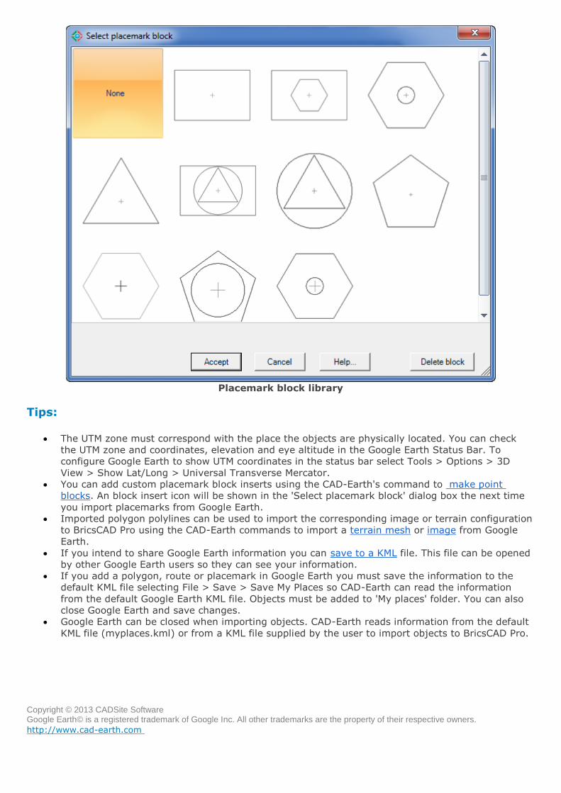
Placemark block library
Tips:
The UTM zone must correspond with the place the objects are physically located. You can check
the UTM zone and coordinates, elevation and eye altitude in the Google Earth Status Bar. To
configure Google Earth to show UTM coordinates in the status bar select Tools > Options > 3D
View > Show Lat/Long > Universal Transverse Mercator.
You can add custom placemark block inserts using the CAD-Earth's command to make point
blocks. An block insert icon will be shown in the 'Select placemark block' dialog box the next time
you import placemarks from Google Earth.
Imported polygon polylines can be used to import the corresponding image or terrain configuration
to BricsCAD Pro using the CAD-Earth commands to import a terrain mesh or image from Google
Earth.
If you intend to share Google Earth information you can save to a KML file. This file can be opened
by other Google Earth users so they can see your information.
If you add a polygon, route or placemark in Google Earth you must save the information to the
default KML file selecting File > Save > Save My Places so CAD-Earth can read the information
from the default Google Earth KML file. Objects must be added to 'My places' folder. You can also
close Google Earth and save changes.
Google Earth can be closed when importing objects. CAD-Earth reads information from the default
KML file (myplaces.kml) or from a KML file supplied by the user to import objects to BricsCAD Pro.
Copyright © 2013 CADSite Software Google Earth© is a registered trademark of Google Inc. All other trademarks are the property of their respective owners.
http://www.cad-earth.com
Navigation: CAD-Earth commands >
Export CAD objects to Google Earth
Toolbar:
Menu: CAD-Earth > Export CAD objects to Google Earth
Command line: CE_EXPGEOBJ
Prompts: Select objects:
CAD-Earth version: Basic, Plus.
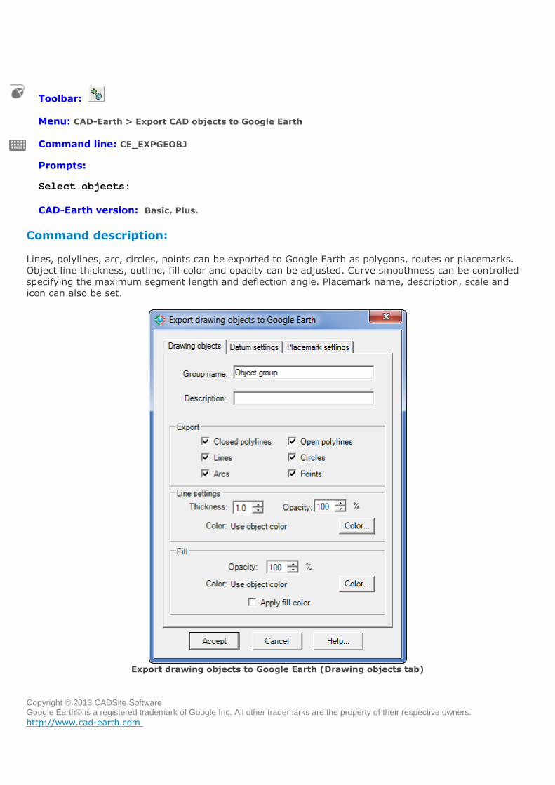
Command description:
Lines, polylines, arc, circles, points can be exported to Google Earth as polygons, routes or placemarks.
Object line thickness, outline, fill color and opacity can be adjusted. Curve smoothness can be controlled
specifying the maximum segment length and deflection angle. Placemark name, description, scale and
icon can also be set.
Export drawing objects to Google Earth (Drawing objects tab)
Copyright © 2013 CADSite Software Google Earth© is a registered trademark of Google Inc. All other trademarks are the property of their respective owners.
http://www.cad-earth.com
Export drawing objects to Google Earth (Drawing objects tab):
Group name. Text entered will be shown as the name of the folder containing the exported
objects.
Group description. Text entered will be shown as the description of the folder containing the
exported objects.
Export.
Closed polylines. Choose to export closed polylines as polygons in Google Earth.
Open polylines. Choose to export open polylines as routes in Google Earth.
Lines. Choose to export lines as routes in Google Earth.
Circles. Choose to export circles as polygons in Google Earth.
Arcs. Choose to export arcs as routes in Google Earth.
Points. Choose to export points as placemarks in Google Earth.
Line settings.
Thickness. Values for line thickness of exported objects can be from 0 to 100 pixels.
Opacity. Values for line opacity of exported objects can be between 0% (line completely
invisible) and 100% (line completely visible)
Color. Objects can be exported to Google Earth with the same color they have in BricsCAD
Pro, using the current color, or with a color selected by the user.
Fill.
Opacity. Closed polylines and circles can be exported to Google Earth with a fill opacity
from 100% (completely visible) to 0% (completely invisible).
Color. Closed polylines and circles can be exported to Google Earth with the same fill color
the have in BricsCAD Pro, using the current color, or with a color selected by the user.
Apply fill color. Choose this option is you wish to apply fill to exported objects such as
closed polylines and circles.
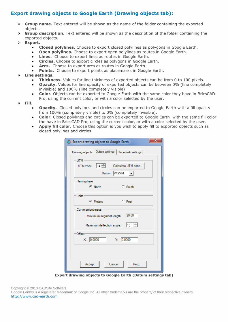
Export drawing objects to Google Earth (Datum settings tab)
Copyright © 2013 CADSite Software Google Earth© is a registered trademark of Google Inc. All other trademarks are the property of their respective owners.
http://www.cad-earth.com
Export drawing objects to Google Earth (Datum settings tab):
UTM
UTM zone. The UTM system divides the Earth between 80°S and 84°N latitude into 60
zones, each 6° of longitude in width. If the UTM zone does not correspond with the object
coordinates the image will not correspond with the site. If you know the approximate
longitude coordinate the UTM zone can be calculated selecting the 'Calculate UTM zone'
button (see fig.)
Calculate UTM zone dialog box
Datum. A datum is defined by a set of constants specifying the coordinate system used for
for calculating the coordinates of points on the Earth. Available datums are WGS84, NAD27
and NAD83. The datum used when the geodetic coordinates were converted to UTM
drawing coordinates must correspond with the datum selected in the list. Google Earth uses
by default the WGS84 datum for coordinate conversion.
Hemisphere. If the site is located above the Earth's Equatorial line the north hemisphere must be
checked, otherwise select the south hemisphere.
Units. The units must correspond with the units used to draw the selected closed polyline. If the
objects were not drawn in meters or feet, they must be rescaled and relocated to match real
coordinates. The feet units must be in US Surveyor's Foot (equal to 0.304800609601219 meters
per feet).
Curve smoothness. Arcs, circles, and polylines with curved segments will be converted to
straight segments before exporting. The number of resulting segments will be proportional to the
maximum segment length and the maximum deflection angle between consecutive segments
specified.
Offset. If you need to adjust the position of the objects exported to Google Earth you can specify
a distance to move in the horizontal (X) and vertical (Y) direction. The distances will be applied in
the units selected (meters or feet).
Copyright © 2013 CADSite Software Google Earth© is a registered trademark of Google Inc. All other trademarks are the property of their respective owners.
http://www.cad-earth.com
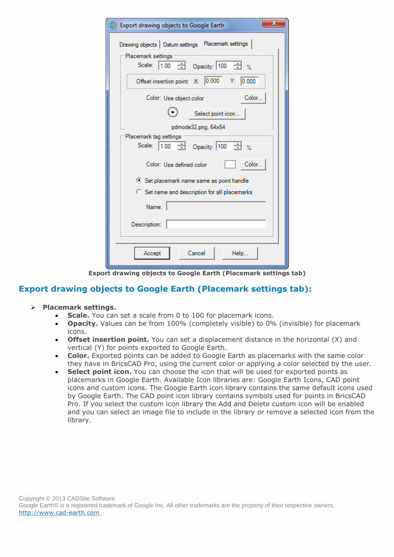
Export drawing objects to Google Earth (Placemark settings tab)
Export drawing objects to Google Earth (Placemark settings tab):
Placemark settings.
Scale. You can set a scale from 0 to 100 for placemark icons.
Opacity. Values can be from 100% (completely visible) to 0% (invisible) for placemark
icons.
Offset insertion point. You can set a displacement distance in the horizontal (X) and
vertical (Y) for points exported to Google Earth.
Color. Exported points can be added to Google Earth as placemarks with the same color
they have in BricsCAD Pro, using the current color or applying a color selected by the user.
Select point icon. You can choose the icon that will be used for exported points as
placemarks in Google Earth. Available Icon libraries are: Google Earth Icons, CAD point
icons and custom icons. The Google Earth icon library contains the same default icons used
by Google Earth. The CAD point icon library contains symbols used for points in BricsCAD
Pro. If you select the custom icon library the Add and Delete custom icon will be enabled
and you can select an image file to include in the library or remove a selected icon from the
library.
Copyright © 2013 CADSite Software Google Earth© is a registered trademark of Google Inc. All other trademarks are the property of their respective owners.
http://www.cad-earth.com
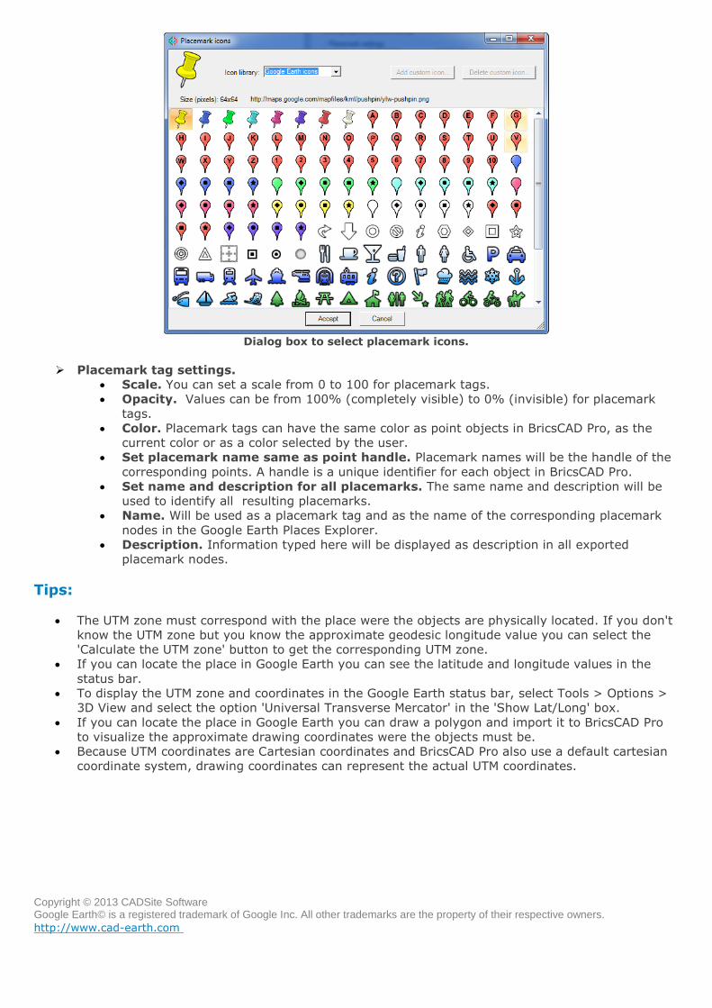
Dialog box to select placemark icons.
Placemark tag settings.
Scale. You can set a scale from 0 to 100 for placemark tags.
Opacity. Values can be from 100% (completely visible) to 0% (invisible) for placemark
tags.
Color. Placemark tags can have the same color as point objects in BricsCAD Pro, as the
current color or as a color selected by the user.
Set placemark name same as point handle. Placemark names will be the handle of the
corresponding points. A handle is a unique identifier for each object in BricsCAD Pro.
Set name and description for all placemarks. The same name and description will be
used to identify all resulting placemarks.
Name. Will be used as a placemark tag and as the name of the corresponding placemark
nodes in the Google Earth Places Explorer.
Description. Information typed here will be displayed as description in all exported
placemark nodes.
Tips:
The UTM zone must correspond with the place were the objects are physically located. If you don't
know the UTM zone but you know the approximate geodesic longitude value you can select the
'Calculate the UTM zone' button to get the corresponding UTM zone.
If you can locate the place in Google Earth you can see the latitude and longitude values in the
status bar.
To display the UTM zone and coordinates in the Google Earth status bar, select Tools > Options >
3D View and select the option 'Universal Transverse Mercator' in the 'Show Lat/Long' box.
If you can locate the place in Google Earth you can draw a polygon and import it to BricsCAD Pro
to visualize the approximate drawing coordinates were the objects must be.
Because UTM coordinates are Cartesian coordinates and BricsCAD Pro also use a default cartesian
coordinate system, drawing coordinates can represent the actual UTM coordinates.
Copyright © 2013 CADSite Software Google Earth© is a registered trademark of Google Inc. All other trademarks are the property of their respective owners.
http://www.cad-earth.com
Navigation: CAD-Earth commands >
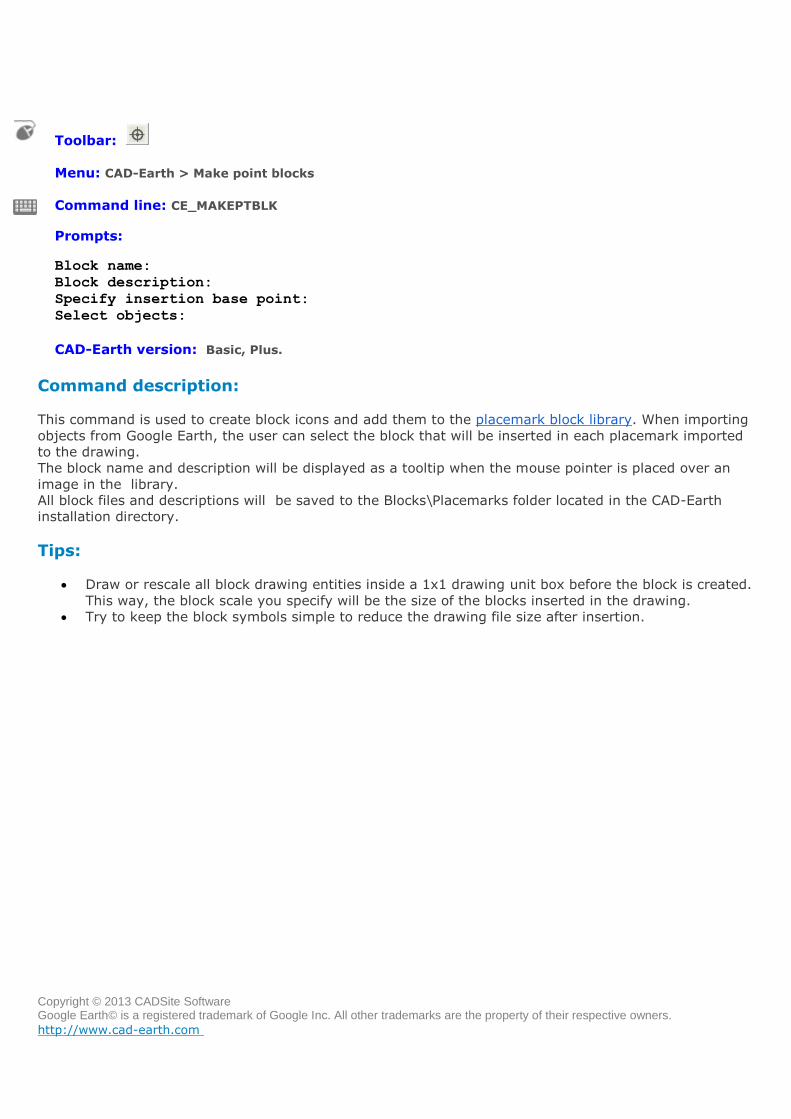
Make point blocks
Toolbar:
Menu: CAD-Earth > Make point blocks
Command line: CE_MAKEPTBLK
Prompts: Block name:
Block description:
Specify insertion base point:
Select objects:
CAD-Earth version: Basic, Plus.
Command description:
This command is used to create block icons and add them to the placemark block library. When importing
objects from Google Earth, the user can select the block that will be inserted in each placemark imported
to the drawing.
The block name and description will be displayed as a tooltip when the mouse pointer is placed over an
image in the library.
All block files and descriptions will be saved to the Blocks\Placemarks folder located in the CAD-Earth
installation directory.
Tips:
Draw or rescale all block drawing entities inside a 1x1 drawing unit box before the block is created.
This way, the block scale you specify will be the size of the blocks inserted in the drawing.
Try to keep the block symbols simple to reduce the drawing file size after insertion.
Copyright © 2013 CADSite Software Google Earth© is a registered trademark of Google Inc. All other trademarks are the property of their respective owners.
http://www.cad-earth.com
Navigation: CAD-Earth commands >
Import terrain mesh from Google Earth
Toolbar:
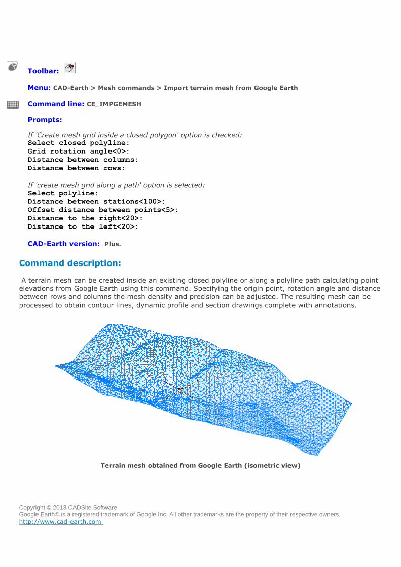
Menu: CAD-Earth > Mesh commands > Import terrain mesh from Google Earth
Command line: CE_IMPGEMESH
Prompts:
If 'Create mesh grid inside a closed polygon' option is checked: Select closed polyline:
Grid rotation angle<0>:
Distance between columns:
Distance between rows:
If 'create mesh grid along a path' option is selected: Select polyline:
Distance between stations<100>:
Offset distance between points<5>:
Distance to the right<20>:
Distance to the left<20>:
CAD-Earth version: Plus.
Command description:
A terrain mesh can be created inside an existing closed polyline or along a polyline path calculating point
elevations from Google Earth using this command. Specifying the origin point, rotation angle and distance
between rows and columns the mesh density and precision can be adjusted. The resulting mesh can be
processed to obtain contour lines, dynamic profile and section drawings complete with annotations.
Terrain mesh obtained from Google Earth (isometric view)
Copyright © 2013 CADSite Software Google Earth© is a registered trademark of Google Inc. All other trademarks are the property of their respective owners.
http://www.cad-earth.com
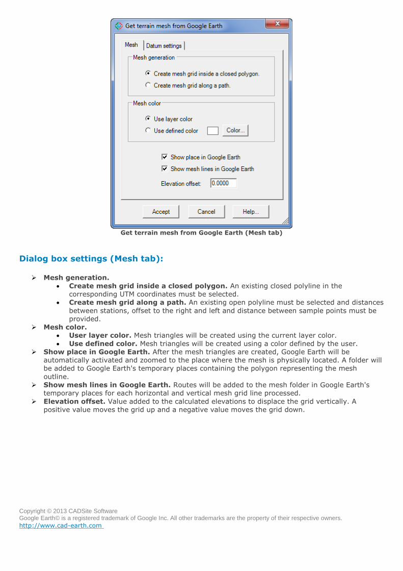
Get terrain mesh from Google Earth (Mesh tab)
Dialog box settings (Mesh tab):
Mesh generation.
Create mesh grid inside a closed polygon. An existing closed polyline in the
corresponding UTM coordinates must be selected.
Create mesh grid along a path. An existing open polyline must be selected and distances
between stations, offset to the right and left and distance between sample points must be
provided.
Mesh color.
User layer color. Mesh triangles will be created using the current layer color.
Use defined color. Mesh triangles will be created using a color defined by the user.
Show place in Google Earth. After the mesh triangles are created, Google Earth will be
automatically activated and zoomed to the place where the mesh is physically located. A folder will
be added to Google Earth's temporary places containing the polygon representing the mesh
outline.
Show mesh lines in Google Earth. Routes will be added to the mesh folder in Google Earth's
temporary places for each horizontal and vertical mesh grid line processed.
Elevation offset. Value added to the calculated elevations to displace the grid vertically. A
positive value moves the grid up and a negative value moves the grid down.
Copyright © 2013 CADSite Software Google Earth© is a registered trademark of Google Inc. All other trademarks are the property of their respective owners.
http://www.cad-earth.com
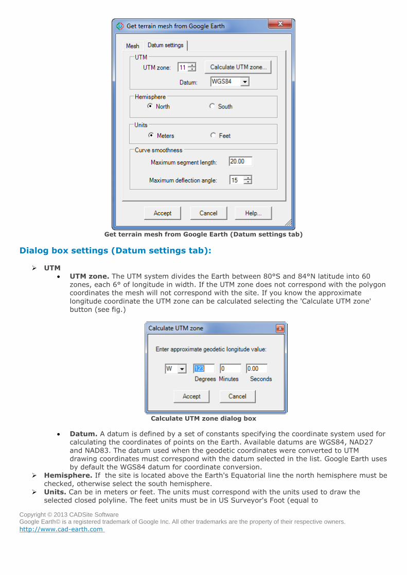
Get terrain mesh from Google Earth (Datum settings tab)
Dialog box settings (Datum settings tab):
UTM
UTM zone. The UTM system divides the Earth between 80°S and 84°N latitude into 60
zones, each 6° of longitude in width. If the UTM zone does not correspond with the polygon
coordinates the mesh will not correspond with the site. If you know the approximate
longitude coordinate the UTM zone can be calculated selecting the 'Calculate UTM zone'
button (see fig.)
Calculate UTM zone dialog box
Datum. A datum is defined by a set of constants specifying the coordinate system used for
calculating the coordinates of points on the Earth. Available datums are WGS84, NAD27
and NAD83. The datum used when the geodetic coordinates were converted to UTM
drawing coordinates must correspond with the datum selected in the list. Google Earth uses
by default the WGS84 datum for coordinate conversion.
Hemisphere. If the site is located above the Earth's Equatorial line the north hemisphere must be
checked, otherwise select the south hemisphere.
Units. Can be in meters or feet. The units must correspond with the units used to draw the
selected closed polyline. The feet units must be in US Surveyor's Foot (equal to
Copyright © 2013 CADSite Software Google Earth© is a registered trademark of Google Inc. All other trademarks are the property of their respective owners.
http://www.cad-earth.com
0.304800609601219 meters).
Curve smoothness. If the closed polyline has curved sides they will be converted to straight
segments before the polygon representing the polygon outline is added to Google Earth. The
number of resulting segments will be proportional to the maximum segment length and the
maximum deflection angle between consecutive segments specified.
Tips:
The terrain configuration in Google Earth is not as accurate as configuration obtained by a
site survey. The resulting mesh is not recommended to be used for projects where high accuracy is
required.
The UTM zone must correspond with the place were the mesh is physically located. If you don't
know the UTM zone but you know the approximate geodetic longitude value you can select the
'Calculate the UTM zone' button to get the corresponding UTM zone.
If you can locate the place in Google Earth you can see the latitude and longitude values in the
Google Earth status bar.
To display the UTM zone and coordinates in the Google Earth status bar, select Tools > Options >
3D View and select the option 'Universal Transverse Mercator' in the 'Show Lat/Long' box.
If you can locate the place in Google Earth you can draw a polygon and import it to BricsCAD Pro
to visualize the approximate drawing coordinates were the mesh must be located.
Because UTM coordinates are Cartesian coordinates and BricsCAD Pro also uses a default cartesian
coordinate system, drawing coordinates can represent the actual UTM coordinates.
Copyright © 2013 CADSite Software Google Earth© is a registered trademark of Google Inc. All other trademarks are the property of their respective owners.
http://www.cad-earth.com
Navigation: CAD-Earth commands >
Contour lines
Toolbar:
Menu: CAD-Earth > Mesh commands > Contour lines.
Command line: CE_CONTOURLINES
Prompts: Select triangulation mesh:
CAD-Earth version: Plus.
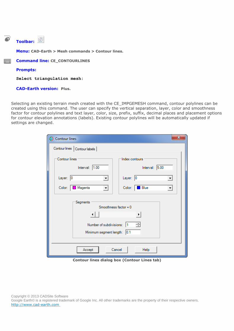
Selecting an existing terrain mesh created with the CE_IMPGEMESH command, contour polylines can be
created using this command. The user can specify the vertical separation, layer, color and smoothness
factor for contour polylines and text layer, color, size, prefix, suffix, decimal places and placement options
for contour elevation annotations (labels). Existing contour polylines will be automatically updated if
settings are changed.
Contour lines dialog box (Contour Lines tab)
Copyright © 2013 CADSite Software Google Earth© is a registered trademark of Google Inc. All other trademarks are the property of their respective owners.
http://www.cad-earth.com
Dialog box settings (Contour lines tab):
Contour lines.
Interval. Vertical separation between contour polylines.
Layer. Contour polylines will be created in the layer selected.
Color. Select color for contour polylines.
Index contours.
Interval. Vertical separation between contour polylines.
Layer. Index contour polylines will be created in the layer selected.
Color. Select color for index contour polylines.
Segments.
Smoothness factor. Enter value between 0 (contours with straight segments) an 10
(rounded contour segments with maximum bulge allowable).
Number of subdivisions. Straight contour segments will be divided by this value before
roundness is applied. If the resulting segment length after subdivision is less than the
minimum specified the minimum segment length will be used to subdivide the contour
segment.
Minimum segment length. Minimum allowable length for contour segments after
subdivision.
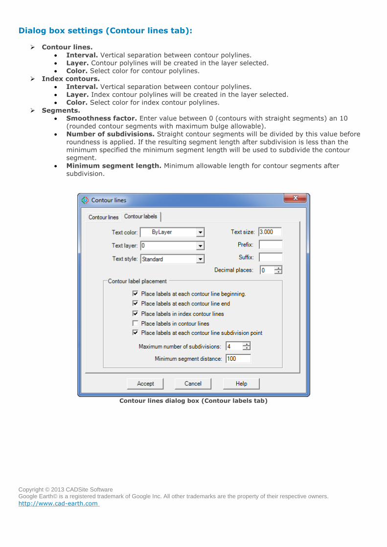
Contour lines dialog box (Contour labels tab)
Copyright © 2013 CADSite Software Google Earth© is a registered trademark of Google Inc. All other trademarks are the property of their respective owners.
http://www.cad-earth.com
Dialog box settings (Contour labels tab):
Text.
Color. Selected color will be used for contour elevation annotations.
Layer. Contour elevation annotations will be drawn in the layer selected.
Style. The color selected will be used for contour elevation annotations.
Size. Height in drawing units for contour elevation annotations.
Prefix. Text entered will be added before contour elevation annotations.
Suffix. Text entered will be appended to contour elevation annotations.
Decimal places.
Contour label placement.
Place labels at each contour line beginning. Contour elevation annotations will be
placed at the beginning of each contour polyline.
Place labels at each contour line end. Contour elevation annotations will be placed at
the end of each contour polyline.
Place labels in index contour lines. Contour elevation annotations will be placed along
each index contour polyline.
Place labels in contour lines. Contour elevation annotations will be placed along each
main contour polyline.
Place labels at each contour line subdivision point. Contour elevation annotations will
be placed along contour polylines at each point resulting from the maximum number of
subdivisions or minimum segment distance.
Maximum number of subdivisions. Contour polylines will be divided by this value. If the
resulting segment length is less than the minimum specified, the minimum segment length
will be used to subdivide the contour polyline for elevation annotation placement.
Minimum segment distance. Minimum allowable segment length for contour polyline
subdivision for elevation annotation placement.
Tips:
The most exact representation of contour lines is achieved by straight segments (smoothness
factor = 0).
Use a smoothness factor of zero if you want to reduce the drawing file size to the maximum by
avoiding the insertion of additional vertices and bulge information in contour polylines.
If rounded contour polylines intersect, reduce the smoothness factor until they don't cross each
other.
Existing contour polylines will be automatically updated if settings are changed.
Copyright © 2013 CADSite Software Google Earth© is a registered trademark of Google Inc. All other trademarks are the property of their respective owners.
http://www.cad-earth.com
Navigation: CAD-Earth commands >
Set mesh visibility
Toolbar:
Menu: CAD-Earth > Mesh commands > Set mesh visibility
Command line: CE_MESHVISIBILITY
Prompts: Select triangulation mesh:
CAD-Earth version: Plus.
Command description:
This command is used to toggle mesh visibility when corresponding contour lines have been created.
Tips:
Use this command to hide the triangulation mesh to see the contour lines more clearly and before
plotting.
If the contour lines haven't been created, the mesh can't be hidden.
Copyright © 2013 CADSite Software Google Earth© is a registered trademark of Google Inc. All other trademarks are the property of their respective owners.
http://www.cad-earth.com
Navigation: CAD-Earth commands >
Draw cross sections from mesh
Toolbar:
Menu: CAD-Earth > Mesh commands > Draw cross section from mesh
Command line: CE_SECTION
Prompts: Select triangulation mesh:
Select polyline inside mesh:
CAD-Earth version: Plus
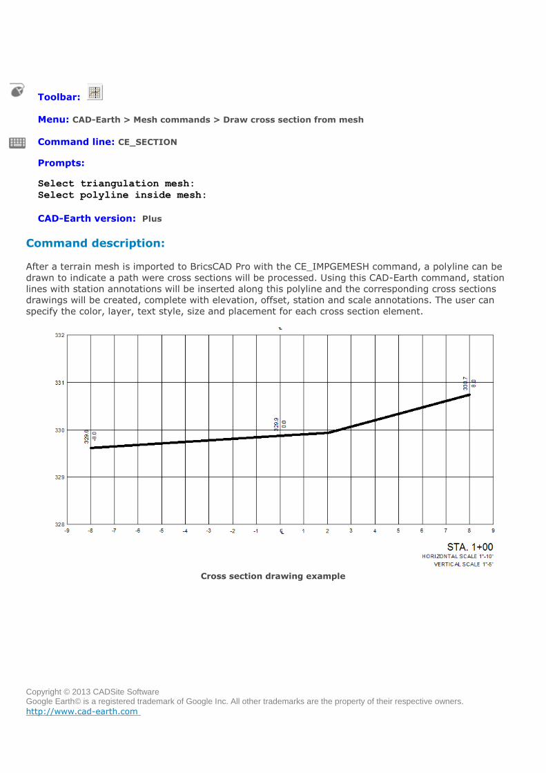
Command description:
After a terrain mesh is imported to BricsCAD Pro with the CE_IMPGEMESH command, a polyline can be
drawn to indicate a path were cross sections will be processed. Using this CAD-Earth command, station
lines with station annotations will be inserted along this polyline and the corresponding cross sections
drawings will be created, complete with elevation, offset, station and scale annotations. The user can
specify the color, layer, text style, size and placement for each cross section element.
Cross section drawing example
Copyright © 2013 CADSite Software Google Earth© is a registered trademark of Google Inc. All other trademarks are the property of their respective owners.
http://www.cad-earth.com
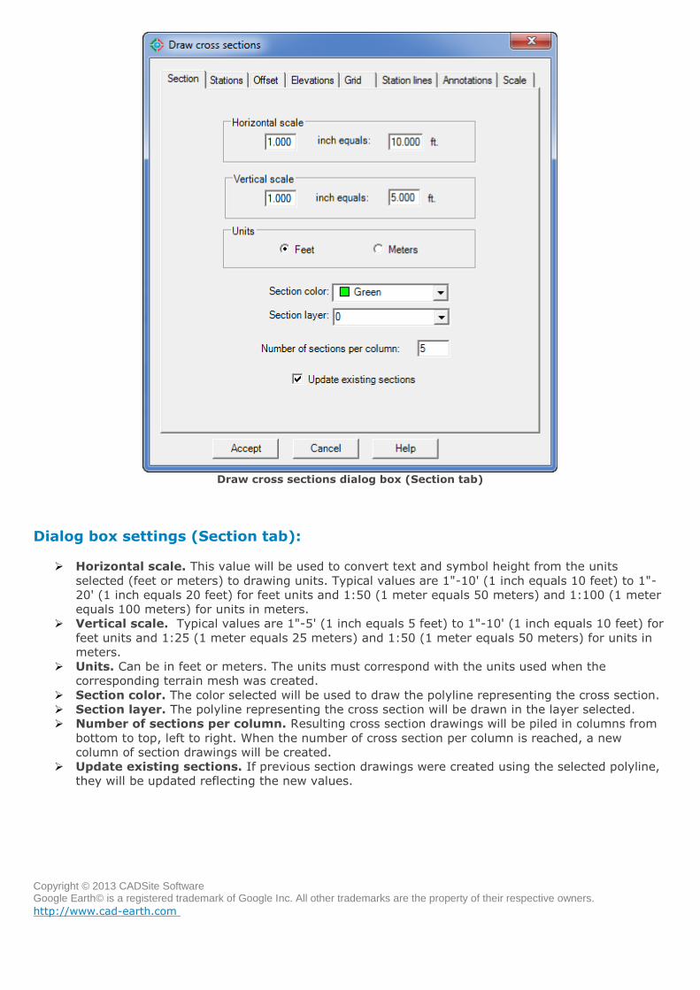
Draw cross sections dialog box (Section tab)
Dialog box settings (Section tab):
Horizontal scale. This value will be used to convert text and symbol height from the units
selected (feet or meters) to drawing units. Typical values are 1"-10' (1 inch equals 10 feet) to 1"-
20' (1 inch equals 20 feet) for feet units and 1:50 (1 meter equals 50 meters) and 1:100 (1 meter
equals 100 meters) for units in meters.
Vertical scale. Typical values are 1"-5' (1 inch equals 5 feet) to 1"-10' (1 inch equals 10 feet) for
feet units and 1:25 (1 meter equals 25 meters) and 1:50 (1 meter equals 50 meters) for units in
meters.
Units. Can be in feet or meters. The units must correspond with the units used when the
corresponding terrain mesh was created.
Section color. The color selected will be used to draw the polyline representing the cross section.
Section layer. The polyline representing the cross section will be drawn in the layer selected.
Number of sections per column. Resulting cross section drawings will be piled in columns from
bottom to top, left to right. When the number of cross section per column is reached, a new
column of section drawings will be created.
Update existing sections. If previous section drawings were created using the selected polyline,
they will be updated reflecting the new values.
Copyright © 2013 CADSite Software Google Earth© is a registered trademark of Google Inc. All other trademarks are the property of their respective owners.
http://www.cad-earth.com
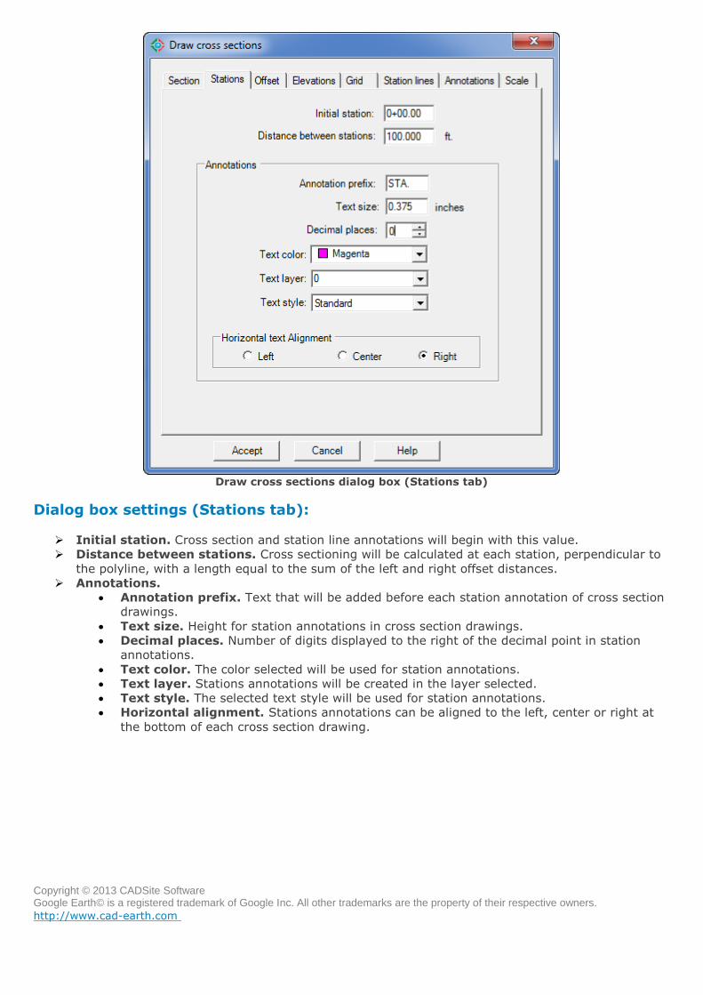
Draw cross sections dialog box (Stations tab)
Dialog box settings (Stations tab):
Initial station. Cross section and station line annotations will begin with this value.
Distance between stations. Cross sectioning will be calculated at each station, perpendicular to
the polyline, with a length equal to the sum of the left and right offset distances.
Annotations.
Annotation prefix. Text that will be added before each station annotation of cross section
drawings.
Text size. Height for station annotations in cross section drawings.
Decimal places. Number of digits displayed to the right of the decimal point in station
annotations.
Text color. The color selected will be used for station annotations.
Text layer. Stations annotations will be created in the layer selected.
Text style. The selected text style will be used for station annotations.
Horizontal alignment. Stations annotations can be aligned to the left, center or right at
the bottom of each cross section drawing.
Copyright © 2013 CADSite Software Google Earth© is a registered trademark of Google Inc. All other trademarks are the property of their respective owners.
http://www.cad-earth.com
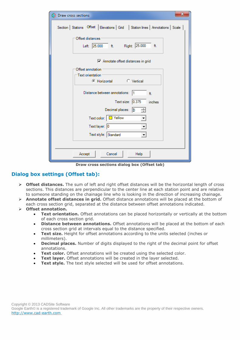
Draw cross sections dialog box (Offset tab)
Dialog box settings (Offset tab):
Offset distances. The sum of left and right offset distances will be the horizontal length of cross
sections. This distances are perpendicular to the center line at each station point and are relative
to someone standing on the chainage line who is looking in the direction of increasing chainage.
Annotate offset distances in grid. Offset distance annotations will be placed at the bottom of
each cross section grid, separated at the distance between offset annotations indicated.
Offset annotation.
Text orientation. Offset annotations can be placed horizontally or vertically at the bottom
of each cross section grid.
Distance between annotations. Offset annotations will be placed at the bottom of each
cross section grid at intervals equal to the distance specified.
Text size. Height for offset annotations according to the units selected (inches or
millimeters).
Decimal places. Number of digits displayed to the right of the decimal point for offset
annotations.
Text color. Offset annotations will be created using the selected color.
Text layer. Offset annotations will be created in the layer selected.
Text style. The text style selected will be used for offset annotations.
Copyright © 2013 CADSite Software Google Earth© is a registered trademark of Google Inc. All other trademarks are the property of their respective owners.
http://www.cad-earth.com
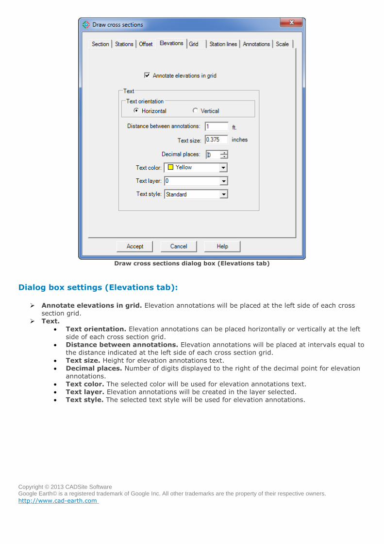
Draw cross sections dialog box (Elevations tab)
Dialog box settings (Elevations tab):
Annotate elevations in grid. Elevation annotations will be placed at the left side of each cross
section grid.
Text.
Text orientation. Elevation annotations can be placed horizontally or vertically at the left
side of each cross section grid.
Distance between annotations. Elevation annotations will be placed at intervals equal to
the distance indicated at the left side of each cross section grid.
Text size. Height for elevation annotations text.
Decimal places. Number of digits displayed to the right of the decimal point for elevation
annotations.
Text color. The selected color will be used for elevation annotations text.
Text layer. Elevation annotations will be created in the layer selected.
Text style. The selected text style will be used for elevation annotations.

Copyright © 2013 CADSite Software Google Earth© is a registered trademark of Google Inc. All other trademarks are the property of their respective owners.
http://www.cad-earth.com
Draw cross sections dialog box (Grid tab)
Dialog box settings (Grid tab):
Draw grid. Select to draw horizontal and vertical lines as reference in each cross section drawing.
Draw grid frame. Choose to draw horizontal an vertical lines outlining each cross section
drawing.
Grid.
Vertical lines spacing. Interval distance between each grid vertical line. Value must be of
integer type.
Horizontal lines spacing. Interval distance between each grid horizontal line. Value must
be of integer type.
Gap between rows. Vertical distance between the top of one cross section grid and the
bottom of the next.
Gap between columns. Horizontal distance between the right side of a cross section grid
and the left side of the next.
Padding. Distances around the left, right, top and bottom of the cross section extents.
Values must be a multiple of the vertical or horizontal grid lines spacing.
Grid lines color. The selected color will be used for grid lines.
Grid lines layer. Cross section grid lines will be created in the layer selected.
Grid frame color. The selected color will be used for horizontal and vertical lines outlining
each cross section grid extents.
Copyright © 2013 CADSite Software Google Earth© is a registered trademark of Google Inc. All other trademarks are the property of their respective owners.
http://www.cad-earth.com
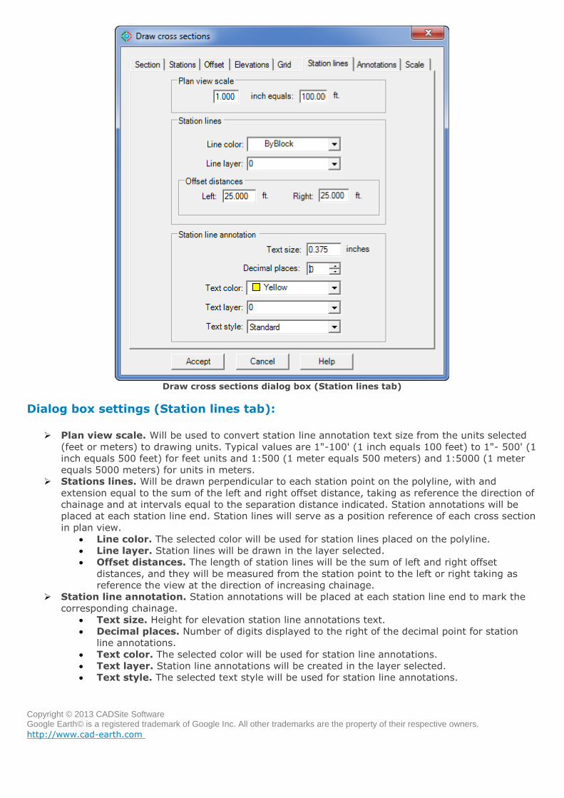
Draw cross sections dialog box (Station lines tab)
Dialog box settings (Station lines tab):
Plan view scale. Will be used to convert station line annotation text size from the units selected
(feet or meters) to drawing units. Typical values are 1"-100' (1 inch equals 100 feet) to 1"- 500' (1
inch equals 500 feet) for feet units and 1:500 (1 meter equals 500 meters) and 1:5000 (1 meter
equals 5000 meters) for units in meters.
Stations lines. Will be drawn perpendicular to each station point on the polyline, with and
extension equal to the sum of the left and right offset distance, taking as reference the direction of
chainage and at intervals equal to the separation distance indicated. Station annotations will be
placed at each station line end. Station lines will serve as a position reference of each cross section
in plan view.
Line color. The selected color will be used for station lines placed on the polyline.
Line layer. Station lines will be drawn in the layer selected.
Offset distances. The length of station lines will be the sum of left and right offset
distances, and they will be measured from the station point to the left or right taking as
reference the view at the direction of increasing chainage.
Station line annotation. Station annotations will be placed at each station line end to mark the
corresponding chainage.
Text size. Height for elevation station line annotations text.
Decimal places. Number of digits displayed to the right of the decimal point for station
line annotations.
Text color. The selected color will be used for station line annotations.
Text layer. Station line annotations will be created in the layer selected.
Text style. The selected text style will be used for station line annotations.
Copyright © 2013 CADSite Software Google Earth© is a registered trademark of Google Inc. All other trademarks are the property of their respective owners.
http://www.cad-earth.com
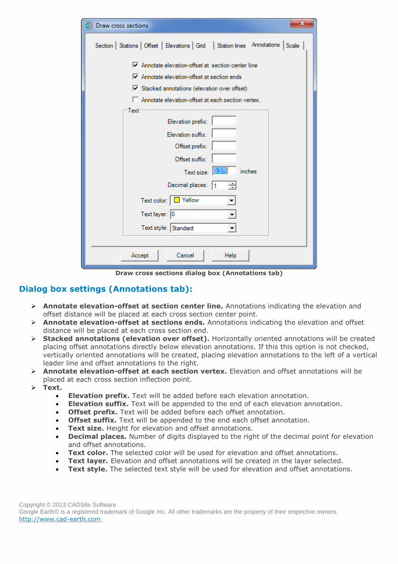
Draw cross sections dialog box (Annotations tab)
Dialog box settings (Annotations tab):
Annotate elevation-offset at section center line. Annotations indicating the elevation and
offset distance will be placed at each cross section center point.
Annotate elevation-offset at sections ends. Annotations indicating the elevation and offset
distance will be placed at each cross section end.
Stacked annotations (elevation over offset). Horizontally oriented annotations will be created
placing offset annotations directly below elevation annotations. If this this option is not checked,
vertically oriented annotations will be created, placing elevation annotations to the left of a vertical
leader line and offset annotations to the right.
Annotate elevation-offset at each section vertex. Elevation and offset annotations will be
placed at each cross section inflection point.
Text.
Elevation prefix. Text will be added before each elevation annotation.
Elevation suffix. Text will be appended to the end of each elevation annotation.
Offset prefix. Text will be added before each offset annotation.
Offset suffix. Text will be appended to the end each offset annotation.
Text size. Height for elevation and offset annotations.
Decimal places. Number of digits displayed to the right of the decimal point for elevation
and offset annotations.
Text color. The selected color will be used for elevation and offset annotations.
Text layer. Elevation and offset annotations will be created in the layer selected.
Text style. The selected text style will be used for elevation and offset annotations.
Copyright © 2013 CADSite Software Google Earth© is a registered trademark of Google Inc. All other trademarks are the property of their respective owners.
http://www.cad-earth.com
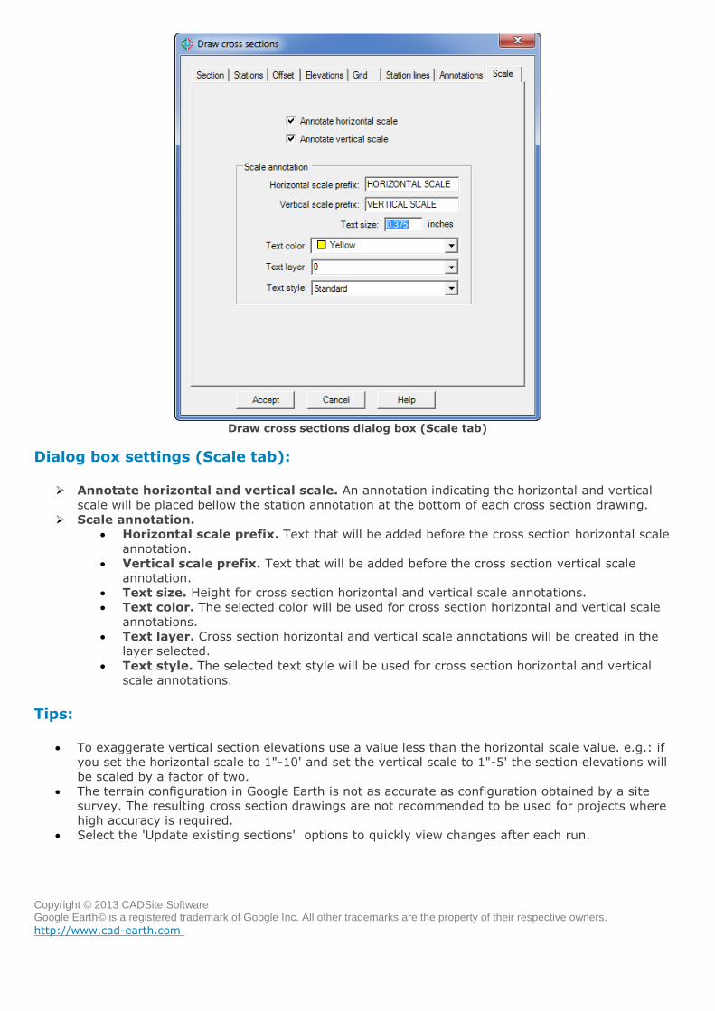
Draw cross sections dialog box (Scale tab)
Dialog box settings (Scale tab):
Annotate horizontal and vertical scale. An annotation indicating the horizontal and vertical
scale will be placed bellow the station annotation at the bottom of each cross section drawing.
Scale annotation.
Horizontal scale prefix. Text that will be added before the cross section horizontal scale
annotation.
Vertical scale prefix. Text that will be added before the cross section vertical scale
annotation.
Text size. Height for cross section horizontal and vertical scale annotations.
Text color. The selected color will be used for cross section horizontal and vertical scale
annotations.
Text layer. Cross section horizontal and vertical scale annotations will be created in the
layer selected.
Text style. The selected text style will be used for cross section horizontal and vertical
scale annotations.
Tips:
To exaggerate vertical section elevations use a value less than the horizontal scale value. e.g.: if
you set the horizontal scale to 1"-10' and set the vertical scale to 1"-5' the section elevations will
be scaled by a factor of two.
The terrain configuration in Google Earth is not as accurate as configuration obtained by a site
survey. The resulting cross section drawings are not recommended to be used for projects where
high accuracy is required.
Select the 'Update existing sections' options to quickly view changes after each run.
Copyright © 2013 CADSite Software Google Earth© is a registered trademark of Google Inc. All other trademarks are the property of their respective owners.
http://www.cad-earth.com
Navigation: CAD-Earth commands >
Annotate cross sections
Toolbar:
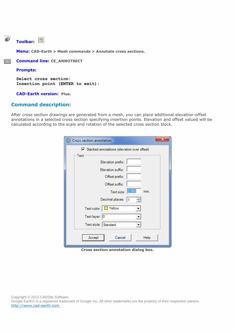
Menu: CAD-Earth > Mesh commands > Annotate cross sections.
Command line: CE_ANNOTSECT
Prompts: Select cross section:
Insertion point (ENTER to exit):
CAD-Earth version: Plus.
Command description:
After cross section drawings are generated from a mesh, you can place additional elevation-offset
annotations in a selected cross section specifying insertion points. Elevation and offset valued will be
calculated according to the scale and rotation of the selected cross section block.
Cross section annotation dialog box.
Copyright © 2013 CADSite Software Google Earth© is a registered trademark of Google Inc. All other trademarks are the property of their respective owners.
http://www.cad-earth.com
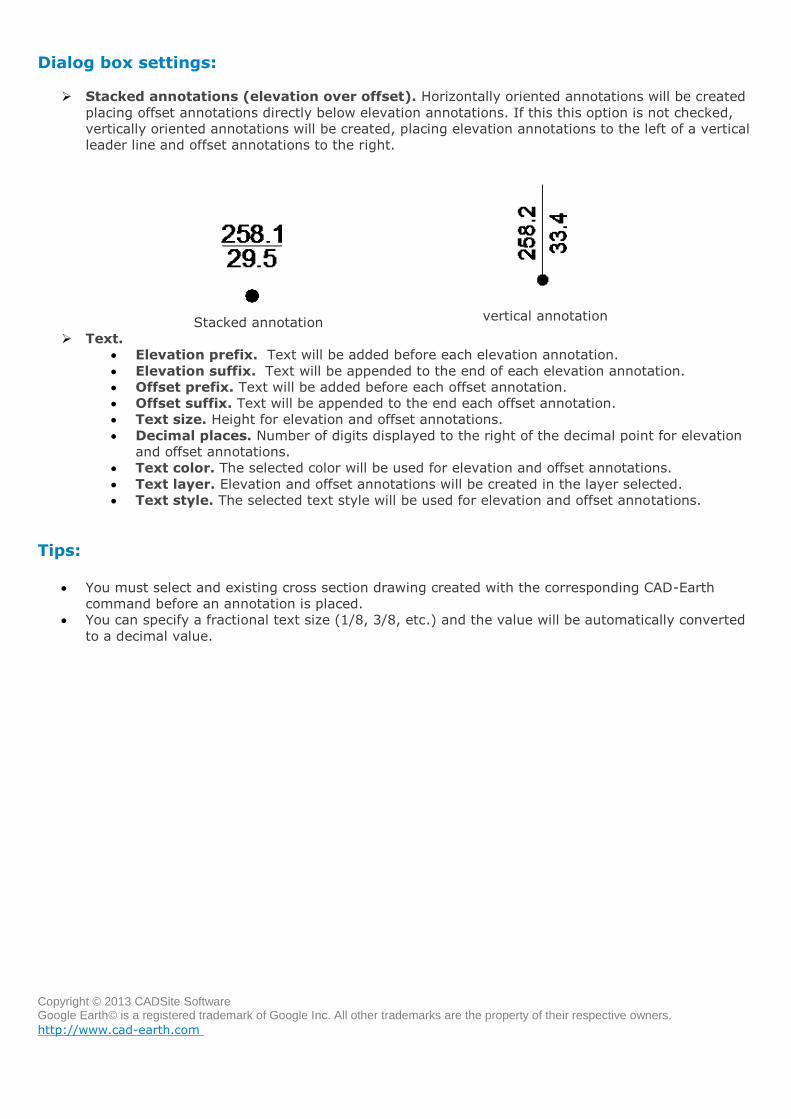
Dialog box settings:
Stacked annotations (elevation over offset). Horizontally oriented annotations will be created
placing offset annotations directly below elevation annotations. If this this option is not checked,
vertically oriented annotations will be created, placing elevation annotations to the left of a vertical
leader line and offset annotations to the right.
Stacked annotation
vertical annotation
Text.
Elevation prefix. Text will be added before each elevation annotation.
Elevation suffix. Text will be appended to the end of each elevation annotation.
Offset prefix. Text will be added before each offset annotation.
Offset suffix. Text will be appended to the end each offset annotation.
Text size. Height for elevation and offset annotations.
Decimal places. Number of digits displayed to the right of the decimal point for elevation
and offset annotations.
Text color. The selected color will be used for elevation and offset annotations.
Text layer. Elevation and offset annotations will be created in the layer selected.
Text style. The selected text style will be used for elevation and offset annotations.
Tips:
You must select and existing cross section drawing created with the corresponding CAD-Earth
command before an annotation is placed.
You can specify a fractional text size (1/8, 3/8, etc.) and the value will be automatically converted
to a decimal value.

Copyright © 2013 CADSite Software Google Earth© is a registered trademark of Google Inc. All other trademarks are the property of their respective owners.
http://www.cad-earth.com
Navigation: CAD-Earth commands >
Draw profile from mesh
Toolbar:
Menu: CAD-Earth > Mesh commands > Draw profile from mesh.
Command line: CE_PROFILE
Prompts: Select triangulation mesh:
Select polyline inside mesh:
CAD-Earth version: Plus.
Command description:
After a terrain mesh is imported to BricsCAD Pro, a polyline can be drawn to indicate a path were a profile
will be extracted. Using this CAD-Earth command, station lines with chainage annotations will be inserted
along the polyline and the corresponding profile drawing will be created, complete with elevation, station
and scale annotations. The user can specify the color, layer, text style, size and placement for each profile
element.
Profile drawing example
Copyright © 2013 CADSite Software Google Earth© is a registered trademark of Google Inc. All other trademarks are the property of their respective owners.
http://www.cad-earth.com
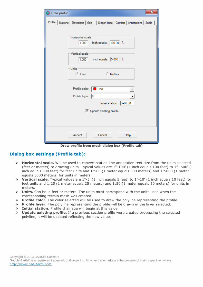
Draw profile from mesh dialog box (Profile tab)
Dialog box settings (Profile tab):
Horizontal scale. Will be used to convert station line annotation text size from the units selected
(feet or meters) to drawing units. Typical values are 1"-100' (1 inch equals 100 feet) to 1"- 500' (1
inch equals 500 feet) for feet units and 1:500 (1 meter equals 500 meters) and 1:5000 (1 meter
equals 5000 meters) for units in meters.
Vertical scale. Typical values are 1"-5' (1 inch equals 5 feet) to 1"-10' (1 inch equals 10 feet) for
feet units and 1:25 (1 meter equals 25 meters) and 1:50 (1 meter equals 50 meters) for units in
meters.
Units. Can be in feet or meters. The units must correspond with the units used when the
corresponding terrain mesh was created.
Profile color. The color selected will be used to draw the polyline representing the profile.
Profile layer. The polyline representing the profile will be drawn in the layer selected.
Initial station. Profile chainage will begin at this value.
Update existing profile. If a previous section profile were created processing the selected
polyline, it will be updated reflecting the new values.
Copyright © 2013 CADSite Software Google Earth© is a registered trademark of Google Inc. All other trademarks are the property of their respective owners.
http://www.cad-earth.com
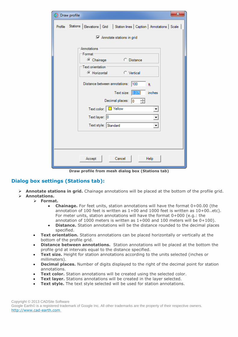
Draw profile from mesh dialog box (Stations tab)
Dialog box settings (Stations tab):
Annotate stations in grid. Chainage annotations will be placed at the bottom of the profile grid.
Annotations.
Format.
Chainage. For feet units, station annotations will have the format 0+00.00 (the
annotation of 100 feet is written as 1+00 and 1000 feet is written as 10+00..etc).
For meter units, station annotations will have the format 0+000 (e.g.: the
annotation of 1000 meters is written as 1+000 and 100 meters will be 0+100).
Distance. Station annotations will be the distance rounded to the decimal places
specified.
Text orientation. Stations annotations can be placed horizontally or vertically at the
bottom of the profile grid.
Distance between annotations. Station annotations will be placed at the bottom the
profile grid at intervals equal to the distance specified.
Text size. Height for station annotations according to the units selected (inches or
millimeters).
Decimal places. Number of digits displayed to the right of the decimal point for station
annotations.
Text color. Station annotations will be created using the selected color.
Text layer. Stations annotations will be created in the layer selected.
Text style. The text style selected will be used for station annotations.
Copyright © 2013 CADSite Software Google Earth© is a registered trademark of Google Inc. All other trademarks are the property of their respective owners.
http://www.cad-earth.com
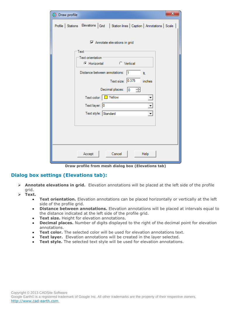
Draw profile from mesh dialog box (Elevations tab)
Dialog box settings (Elevations tab):
Annotate elevations in grid. Elevation annotations will be placed at the left side of the profile
grid.
Text.
Text orientation. Elevation annotations can be placed horizontally or vertically at the left
side of the profile grid.
Distance between annotations. Elevation annotations will be placed at intervals equal to
the distance indicated at the left side of the profile grid.
Text size. Height for elevation annotations.
Decimal places. Number of digits displayed to the right of the decimal point for elevation
annotations.
Text color. The selected color will be used for elevation annotations text.
Text layer. Elevation annotations will be created in the layer selected.
Text style. The selected text style will be used for elevation annotations.
Copyright © 2013 CADSite Software Google Earth© is a registered trademark of Google Inc. All other trademarks are the property of their respective owners.
http://www.cad-earth.com
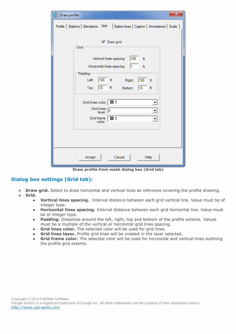
Draw profile from mesh dialog box (Grid tab)
Dialog box settings (Grid tab):
Draw grid. Select to draw horizontal and vertical lines as reference covering the profile drawing.
Grid.
Vertical lines spacing. Interval distance between each grid vertical line. Value must be of
integer type.
Horizontal lines spacing. Interval distance between each grid horizontal line. Value must
be of integer type.
Padding. Distances around the left, right, top and bottom of the profile extents. Values
must be a multiple of the vertical or horizontal grid lines spacing.
Grid lines color. The selected color will be used for grid lines.
Grid lines layer. Profile grid lines will be created in the layer selected.
Grid frame color. The selected color will be used for horizontal and vertical lines outlining
the profile grid extents.
Copyright © 2013 CADSite Software Google Earth© is a registered trademark of Google Inc. All other trademarks are the property of their respective owners.
http://www.cad-earth.com
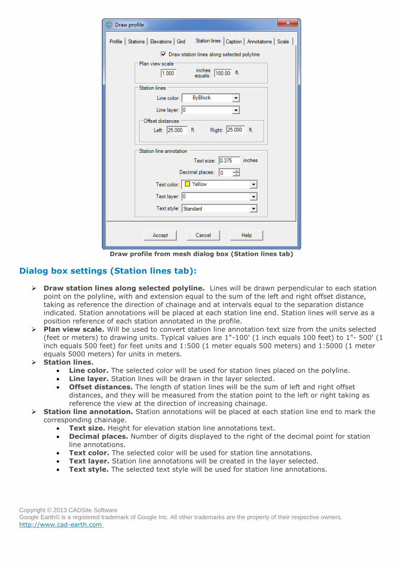
Draw profile from mesh dialog box (Station lines tab)
Dialog box settings (Station lines tab):
Draw station lines along selected polyline. Lines will be drawn perpendicular to each station
point on the polyline, with and extension equal to the sum of the left and right offset distance,
taking as reference the direction of chainage and at intervals equal to the separation distance
indicated. Station annotations will be placed at each station line end. Station lines will serve as a
position reference of each station annotated in the profile.
Plan view scale. Will be used to convert station line annotation text size from the units selected
(feet or meters) to drawing units. Typical values are 1"-100' (1 inch equals 100 feet) to 1"- 500' (1
inch equals 500 feet) for feet units and 1:500 (1 meter equals 500 meters) and 1:5000 (1 meter
equals 5000 meters) for units in meters.
Station lines.
Line color. The selected color will be used for station lines placed on the polyline.
Line layer. Station lines will be drawn in the layer selected.
Offset distances. The length of station lines will be the sum of left and right offset
distances, and they will be measured from the station point to the left or right taking as
reference the view at the direction of increasing chainage.
Station line annotation. Station annotations will be placed at each station line end to mark the
corresponding chainage.
Text size. Height for elevation station line annotations text.
Decimal places. Number of digits displayed to the right of the decimal point for station
line annotations.
Text color. The selected color will be used for station line annotations.
Text layer. Station line annotations will be created in the layer selected.
Text style. The selected text style will be used for station line annotations.
Copyright © 2013 CADSite Software Google Earth© is a registered trademark of Google Inc. All other trademarks are the property of their respective owners.
http://www.cad-earth.com
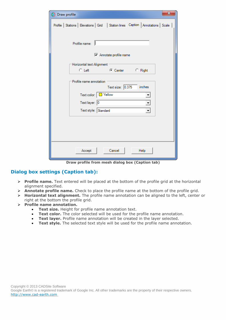
Draw profile from mesh dialog box (Caption tab)
Dialog box settings (Caption tab):
Profile name. Text entered will be placed at the bottom of the profile grid at the horizontal
alignment specified.
Annotate profile name. Check to place the profile name at the bottom of the profile grid.
Horizontal text alignment. The profile name annotation can be aligned to the left, center or
right at the bottom the profile grid.
Profile name annotation.
Text size. Height for profile name annotation text.
Text color. The color selected will be used for the profile name annotation.
Text layer. Profile name annotation will be created in the layer selected.
Text style. The selected text style will be used for the profile name annotation.
Copyright © 2013 CADSite Software Google Earth© is a registered trademark of Google Inc. All other trademarks are the property of their respective owners.
http://www.cad-earth.com
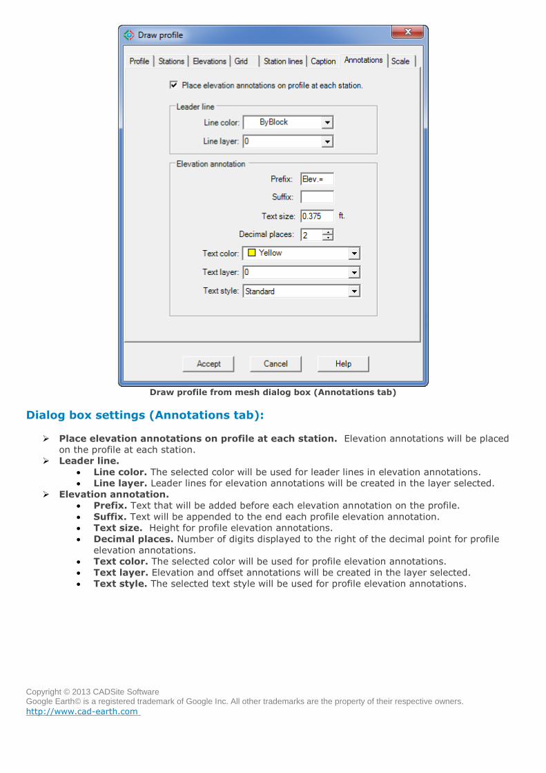
Draw profile from mesh dialog box (Annotations tab)
Dialog box settings (Annotations tab):
Place elevation annotations on profile at each station. Elevation annotations will be placed
on the profile at each station.
Leader line.
Line color. The selected color will be used for leader lines in elevation annotations.
Line layer. Leader lines for elevation annotations will be created in the layer selected.
Elevation annotation.
Prefix. Text that will be added before each elevation annotation on the profile.
Suffix. Text will be appended to the end each profile elevation annotation.
Text size. Height for profile elevation annotations.
Decimal places. Number of digits displayed to the right of the decimal point for profile
elevation annotations.
Text color. The selected color will be used for profile elevation annotations.
Text layer. Elevation and offset annotations will be created in the layer selected.
Text style. The selected text style will be used for profile elevation annotations.
Copyright © 2013 CADSite Software Google Earth© is a registered trademark of Google Inc. All other trademarks are the property of their respective owners.
http://www.cad-earth.com
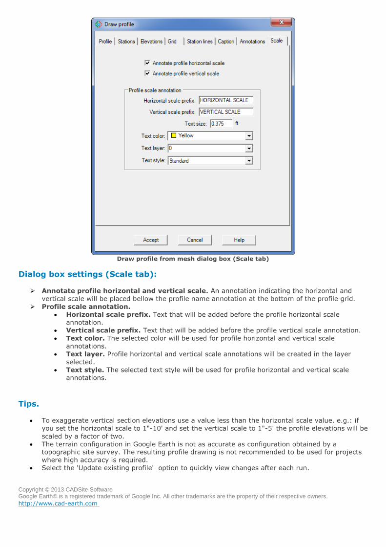
Draw profile from mesh dialog box (Scale tab)
Dialog box settings (Scale tab):
Annotate profile horizontal and vertical scale. An annotation indicating the horizontal and
vertical scale will be placed bellow the profile name annotation at the bottom of the profile grid.
Profile scale annotation.
Horizontal scale prefix. Text that will be added before the profile horizontal scale
annotation.
Vertical scale prefix. Text that will be added before the profile vertical scale annotation.
Text color. The selected color will be used for profile horizontal and vertical scale
annotations.
Text layer. Profile horizontal and vertical scale annotations will be created in the layer
selected.
Text style. The selected text style will be used for profile horizontal and vertical scale
annotations.
Tips.
To exaggerate vertical section elevations use a value less than the horizontal scale value. e.g.: if
you set the horizontal scale to 1"-10' and set the vertical scale to 1"-5' the profile elevations will be
scaled by a factor of two.
The terrain configuration in Google Earth is not as accurate as configuration obtained by a
topographic site survey. The resulting profile drawing is not recommended to be used for projects
where high accuracy is required.
Select the 'Update existing profile' option to quickly view changes after each run.
Copyright © 2013 CADSite Software Google Earth© is a registered trademark of Google Inc. All other trademarks are the property of their respective owners.
http://www.cad-earth.com
Navigation: CAD-Earth commands >
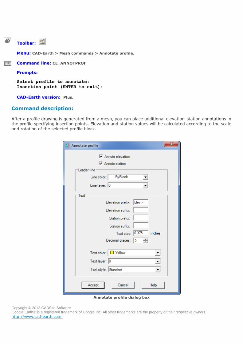
Annotate profile
Toolbar:
Menu: CAD-Earth > Mesh commands > Annotate profile.
Command line: CE_ANNOTPROF
Prompts: Select profile to annotate:
Insertion point (ENTER to exit):
CAD-Earth version: Plus.
Command description:
After a profile drawing is generated from a mesh, you can place additional elevation-station annotations in
the profile specifying insertion points. Elevation and station values will be calculated according to the scale
and rotation of the selected profile block.
Annotate profile dialog box
Copyright © 2013 CADSite Software Google Earth© is a registered trademark of Google Inc. All other trademarks are the property of their respective owners.
http://www.cad-earth.com
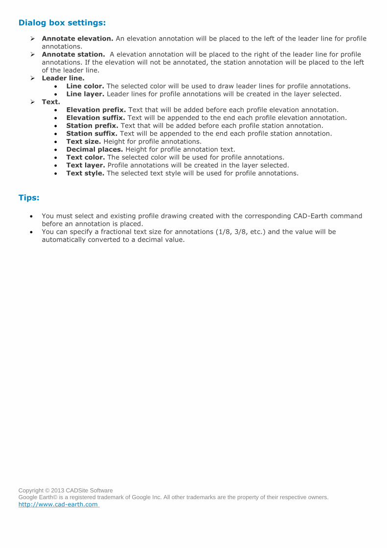
Dialog box settings:
Annotate elevation. An elevation annotation will be placed to the left of the leader line for profile
annotations.
Annotate station. A elevation annotation will be placed to the right of the leader line for profile
annotations. If the elevation will not be annotated, the station annotation will be placed to the left
of the leader line.
Leader line.
Line color. The selected color will be used to draw leader lines for profile annotations.
Line layer. Leader lines for profile annotations will be created in the layer selected.
Text.
Elevation prefix. Text that will be added before each profile elevation annotation.
Elevation suffix. Text will be appended to the end each profile elevation annotation.
Station prefix. Text that will be added before each profile station annotation.
Station suffix. Text will be appended to the end each profile station annotation.
Text size. Height for profile annotations.
Decimal places. Height for profile annotation text.
Text color. The selected color will be used for profile annotations.
Text layer. Profile annotations will be created in the layer selected.
Text style. The selected text style will be used for profile annotations.
Tips:
You must select and existing profile drawing created with the corresponding CAD-Earth command
before an annotation is placed.
You can specify a fractional text size for annotations (1/8, 3/8, etc.) and the value will be
automatically converted to a decimal value.

Copyright © 2013 CADSite Software Google Earth© is a registered trademark of Google Inc. All other trademarks are the property of their respective owners.
http://www.cad-earth.com
Navigation: CAD-Earth commands >
Slope analysis
Toolbar:
Menu: CAD-Earth > Mesh commands > Slope analysis.
Command line: CE_SLOPEANALYSIS
Prompts: Select triangulation mesh:
Position:
CAD-Earth version: Plus.
Command description:
This command is used to color-code mesh triangles according to the slope range they are in. The start
and end slope values of the range are specified and a color is chosen for each slope range. The slope
representation is done by applying a solid HATCH to each slope zone found. A slope zone analysis legend
block will be created when this command ends, allowing the user to select the insertion point and scale.
Slope zone analysis dialog box (Ranges tab)
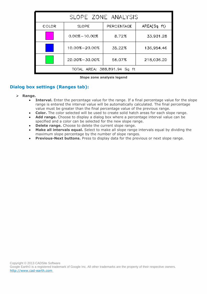
Copyright © 2013 CADSite Software Google Earth© is a registered trademark of Google Inc. All other trademarks are the property of their respective owners.
http://www.cad-earth.com
Slope zone analysis legend
Dialog box settings (Ranges tab):
Range.
Interval. Enter the percentage value for the range. If a final percentage value for the slope
range is entered the interval value will be automatically calculated. The final percentage
value must be greater than the final percentage value of the previous range.
Color. The color selected will be used to create solid hatch areas for each slope range.
Add range. Choose to display a dialog box where a percentage interval value can be
specified and a color can be selected for the new slope range.
Delete range. Choose to delete the current slope range.
Make all intervals equal. Select to make all slope range intervals equal by dividing the
maximum slope percentage by the number of slope ranges.
Previous-Next buttons. Press to display data for the previous or next slope range.
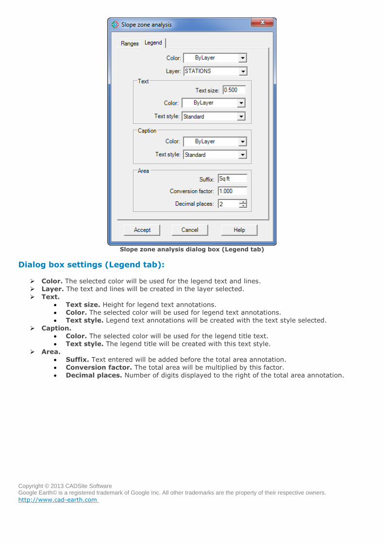
Copyright © 2013 CADSite Software Google Earth© is a registered trademark of Google Inc. All other trademarks are the property of their respective owners.
http://www.cad-earth.com
Slope zone analysis dialog box (Legend tab)
Dialog box settings (Legend tab):
Color. The selected color will be used for the legend text and lines.
Layer. The text and lines will be created in the layer selected.
Text.
Text size. Height for legend text annotations.
Color. The selected color will be used for legend text annotations.
Text style. Legend text annotations will be created with the text style selected.
Caption.
Color. The selected color will be used for the legend title text.
Text style. The legend title will be created with this text style.
Area.
Suffix. Text entered will be added before the total area annotation.
Conversion factor. The total area will be multiplied by this factor.
Decimal places. Number of digits displayed to the right of the total area annotation.
Copyright © 2013 CADSite Software Google Earth© is a registered trademark of Google Inc. All other trademarks are the property of their respective owners.
http://www.cad-earth.com
Navigation: CAD-Earth commands >
License manager
Toolbar:
Menu: CAD-Earth > Help > License manager.
Command line: CE_LICMAN
CAD-Earth version: Basic, Plus.
Command description:
The License Manager is where the activation code is applied to authorize the use of CAD-Earth. You can
also get a deactivation code to be able to regenerate an activation code for another computer.
To get a valid activation code you must go to the License Activation Center website and access your
account. The access user name and password will be sent to you immediately after purchase confirmation
to your email.
If you forgot you password you can receive it in your registered email by giving your user name in the
login page. If you have problems getting or applying an activation code please contact technical support
by selecting 'Contact technical support' in the CAD-Earth Help menu or by sending an email to
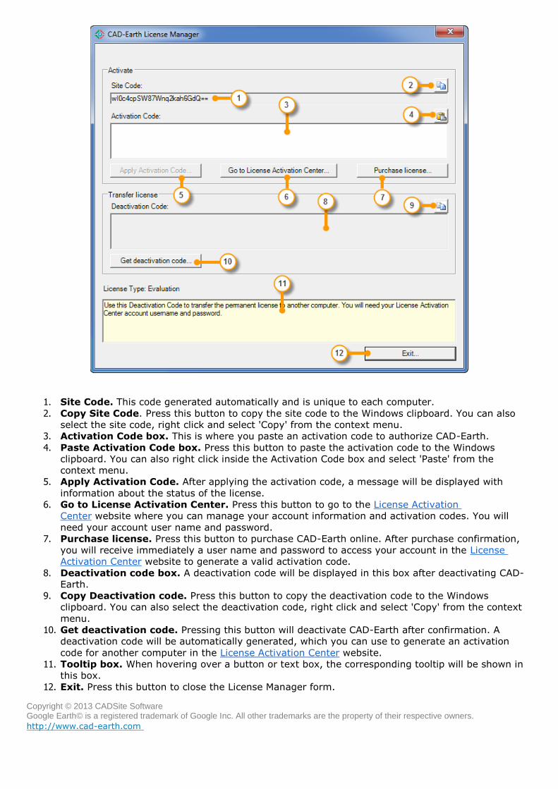
Copyright © 2013 CADSite Software Google Earth© is a registered trademark of Google Inc. All other trademarks are the property of their respective owners.
http://www.cad-earth.com
1. Site Code. This code generated automatically and is unique to each computer.
2. Copy Site Code. Press this button to copy the site code to the Windows clipboard. You can also
select the site code, right click and select 'Copy' from the context menu.
3. Activation Code box. This is where you paste an activation code to authorize CAD-Earth.
4. Paste Activation Code box. Press this button to paste the activation code to the Windows
clipboard. You can also right click inside the Activation Code box and select 'Paste' from the
context menu.
5. Apply Activation Code. After applying the activation code, a message will be displayed with
information about the status of the license.
6. Go to License Activation Center. Press this button to go to the License Activation
Center website where you can manage your account information and activation codes. You will
need your account user name and password.
7. Purchase license. Press this button to purchase CAD-Earth online. After purchase confirmation,
you will receive immediately a user name and password to access your account in the License
Activation Center website to generate a valid activation code.
8. Deactivation code box. A deactivation code will be displayed in this box after deactivating CAD-
Earth.
9. Copy Deactivation code. Press this button to copy the deactivation code to the Windows
clipboard. You can also select the deactivation code, right click and select 'Copy' from the context
menu.
10. Get deactivation code. Pressing this button will deactivate CAD-Earth after confirmation. A
deactivation code will be automatically generated, which you can use to generate an activation
code for another computer in the License Activation Center website.
11. Tooltip box. When hovering over a button or text box, the corresponding tooltip will be shown in
this box.
12. Exit. Press this button to close the License Manager form.

Copyright © 2013 CADSite Software Google Earth© is a registered trademark of Google Inc. All other trademarks are the property of their respective owners.
http://www.cad-earth.com
gation: CAD-Earth commands >
License Activation Center
In the License Activation website you can manage your account information and activation codes.
After purchase confirmation, you will immediately receive a user name and password by email to access
your account. You can select 'Go to License Activation Center...' in the CAD-Earth help menu or in License
Manager button to go to the login page.
Activation codes can be generated, removed or updated. To generate an activation code you must enter
the site code from your computer. This site code can be copied from the License Manager site code box
and then pasted in the License Activation Center site code box.
A deactivation code is needed to remove or update an activation code. To remove an activation code you
must enter the deactivation code from the old computer. For each activation code removed successfully,
you can generate a new activation code for another computer.
If you update an activation code, you must enter the deactivation code from the old computer and enter
the site code from the new computer. The process of eliminating the activation code and generating a new
one will be performed in one step.
Fig. 1: License Activation Center login web page.
1. User name and password boxes. After purchase confirmation, you will receive an email with a
valid user name and password.
2. Remember me. If this box is checked, you can go directly to your account web page again in the
same session without entering your user name and password.
3. Login button. Press this button to go to you account web page.
4. Forgot password?. Following this link you can enter your user name and receive the
corresponding access password by email.
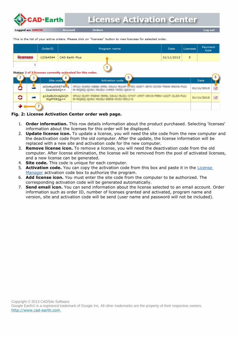
Copyright © 2013 CADSite Software Google Earth© is a registered trademark of Google Inc. All other trademarks are the property of their respective owners.
http://www.cad-earth.com
Fig. 2: License Activation Center order web page.
1. Order information. This row details information about the product purchased. Selecting 'licenses'
information about the licenses for this order will be displayed.
2. Update license icon. To update a license, you will need the site code from the new computer and
the deactivation code from the old computer. After the update, the license information will be
replaced with a new site and activation code for the new computer.
3. Remove license icon. To remove a license, you will need the deactivation code from the old
computer. After license elimination, the license will be removed from the pool of activated licenses,
and a new license can be generated.
4. Site code. This code is unique for each computer.
5. Activation code. You can copy the activation code from this box and paste it in the License
Manager activation code box to authorize the program.
6. Add license icon. You must enter the site code from the computer to be authorized. The
corresponding activation code will be generated automatically.
7. Send email icon. You can send information about the license selected to an email account. Order
information such as order ID, number of licenses granted and activated, program name and
version, site and activation code will be send (user name and password will not be included).
Copyright © 2013 CADSite Software Google Earth© is a registered trademark of Google Inc. All other trademarks are the property of their respective owners.
http://www.cad-earth.com
Navigation: CAD-Earth commands >
Contacting technical support
If you get any error or have any problem using CAD-Earth you can contact our technical support
department.
It is recommended that you send your request by selecting 'Contact technical support' in the CAD-Earth
help menu. This way, information about your computer hardware, Windows and BricsCAD Pro version will
be send to us, with a detailed technical error description which will help us fix the error in the quickest
way possible.
You can select 'Request new feature' in the CAD-Earth help menu if you would like a new function or
capability to be included in a CAD-Earth version update. You can attach files if you like to describe in more
detail your suggestion (Word©, Excel©, DWG©, image and PDF files preferred).
You can also contact in the following email addresses:
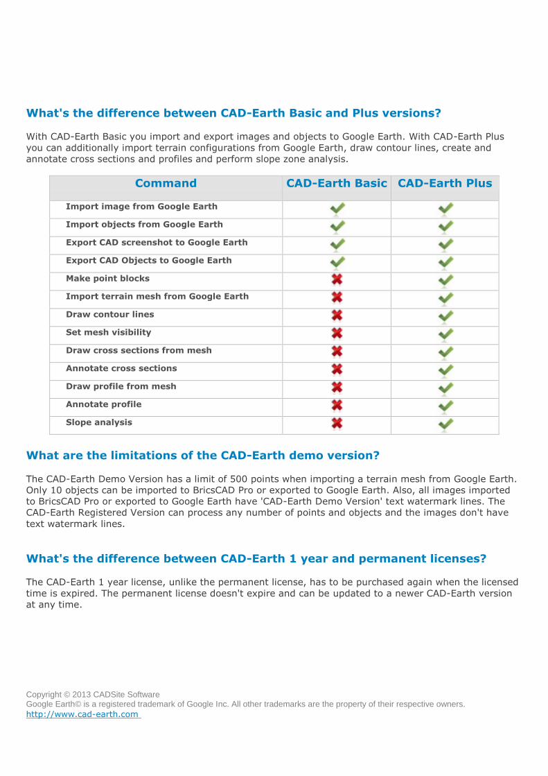
Copyright © 2013 CADSite Software Google Earth© is a registered trademark of Google Inc. All other trademarks are the property of their respective owners.
http://www.cad-earth.com
Navigation: CAD-Earth
Frequently Asked Questions (FAQ)
What's the difference between CAD-Earth Basic and Plus versions?
With CAD-Earth Basic you import and export images and objects to Google Earth. With CAD-Earth Plus
you can additionally import terrain configurations from Google Earth, draw contour lines, create and
annotate cross sections and profiles and perform slope zone analysis.
Command CAD-Earth Basic CAD-Earth Plus
Import image from Google Earth
Import objects from Google Earth
Export CAD screenshot to Google Earth
Export CAD Objects to Google Earth
Make point blocks
Import terrain mesh from Google Earth
Draw contour lines
Set mesh visibility
Draw cross sections from mesh
Annotate cross sections
Draw profile from mesh
Annotate profile
Slope analysis
What are the limitations of the CAD-Earth demo version?
The CAD-Earth Demo Version has a limit of 500 points when importing a terrain mesh from Google Earth.
Only 10 objects can be imported to BricsCAD Pro or exported to Google Earth. Also, all images imported
to BricsCAD Pro or exported to Google Earth have 'CAD-Earth Demo Version' text watermark lines. The
CAD-Earth Registered Version can process any number of points and objects and the images don't have
text watermark lines.
What's the difference between CAD-Earth 1 year and permanent licenses?
The CAD-Earth 1 year license, unlike the permanent license, has to be purchased again when the licensed
time is expired. The permanent license doesn't expire and can be updated to a newer CAD-Earth version
at any time.
Copyright © 2013 CADSite Software Google Earth© is a registered trademark of Google Inc. All other trademarks are the property of their respective owners.
http://www.cad-earth.com
What are the system requirements to use CAD-Earth? CAD-Earth doesn't need any additional requirements from the ones needed to run BricsCAD Pro optimally
(please consult your documentation). Google Earth Free or Pro version 5 or newer must be installed in
your computer. If you don't have Google Earth installed you can download the free version from:
http://www.google.com/earth/download/ge/agree.html
Also, the Google Earth Plug-in must be installed in your web browser. To install the Google Earth Plug-in
you can go to: http://www.google.com/earth/explore/products/plugin.html
How can I transfer a CAD-Earth license to another computer?
To transfer a license to another computer you must first get a deactivation code from the authorized
computer in the CAD-Earth License Manager. Then you must access your account in the CAD-Earth
License Activation Center and enter the site code and deactivation code to update the corresponding
license for the new computer.