cad design and identification of hydrodynamic …cad design and identi cation of hydrodynamic...
TRANSCRIPT
CAD design and Identification of HydrodynamicParameters of an Underwater Glider Vehicle
Jorge Dıaz Moreno1, Reynaldo Ortız Perez1, Eduardo Campos Mercado1,Luis Fidel Cerecero Natale1,2
1 Universidad Politecnica de Pachuca, Posgrado en Mecatronica,Zempoala, Hgo., Mexico
2 Instituto Tecnologico de Cancun, Ingenierıa en Mecatronica,Cancun, Quintana Roo, Mexico
Abstract. This article describes the design, modeling and identificationof the main hydrodynamic parameters of an underwater glider vehicleis presented. The equations describing the dynamics of the vehicle isobtained from the Euler-Lagrange method. The main hydrodynamicparameters were obtained considering the geometry of the vehicle andits operating characteristics. Finally, simulation open loop system arepresented.
Keywords: Hydrodynamic parameters, underwater glider vehicle.
1 Introduction
Unmanned underwater vehicles are classified in ROV’s (Remotely OperatedVehicle) and AUV vehicles (Autonomous Underwater Vehicles) [8]. The Glidersare a type of AUV that control their own buoyancy and can spend long periodsof time under water due to its autonomy low power consumption, because theyusually do not use propellers or cables to the ship [4]. The diversity of underwateractivities is wide and Gliders have efficient ways to perform tasks such as: tocontribute to research, inspections and assessments, exploration of marine floraand fauna, deep-sea exploration for oil projects, search and rescue of objects inareas risk to humans [7].
The Gliders are underwater vehicles designed to carry out exploration, inspec-tion, maintenance and surveillance, among others [8]. Most gliders have a cylind-rical shape, this to minimize the effect of hydrodynamic damping and consequentlythe lower the energy required for vehicle propulsion [6].
The same laws of hydrodynamics governing the flow of the medium and theforces for air carriers can apply for underwater vehicles, but due to the highdensity of water (800 times greater than air) add effects buoyancy and massesadded that they are significant in the dynamics of Glider [9]. The characteristicmovement of a Glider describes a pattern in the form of sawtooth as shown in
125
ISSN 1870-4069
Research in Computing Science 121 (2016)pp. 125–137; rec. 2016-05-24; acc. 2016-08-25
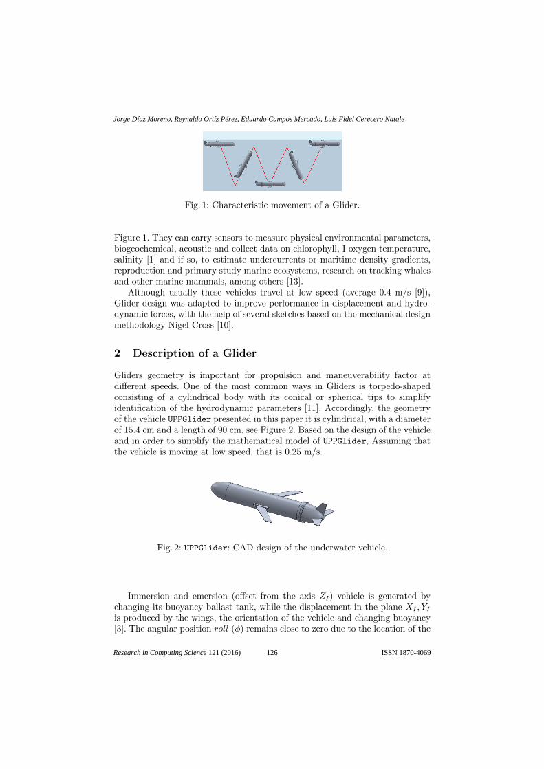
Fig. 1: Characteristic movement of a Glider.
Figure 1. They can carry sensors to measure physical environmental parameters,biogeochemical, acoustic and collect data on chlorophyll, I oxygen temperature,salinity [1] and if so, to estimate undercurrents or maritime density gradients,reproduction and primary study marine ecosystems, research on tracking whalesand other marine mammals, among others [13].
Although usually these vehicles travel at low speed (average 0.4 m/s [9]),Glider design was adapted to improve performance in displacement and hydro-dynamic forces, with the help of several sketches based on the mechanical designmethodology Nigel Cross [10].
2 Description of a Glider
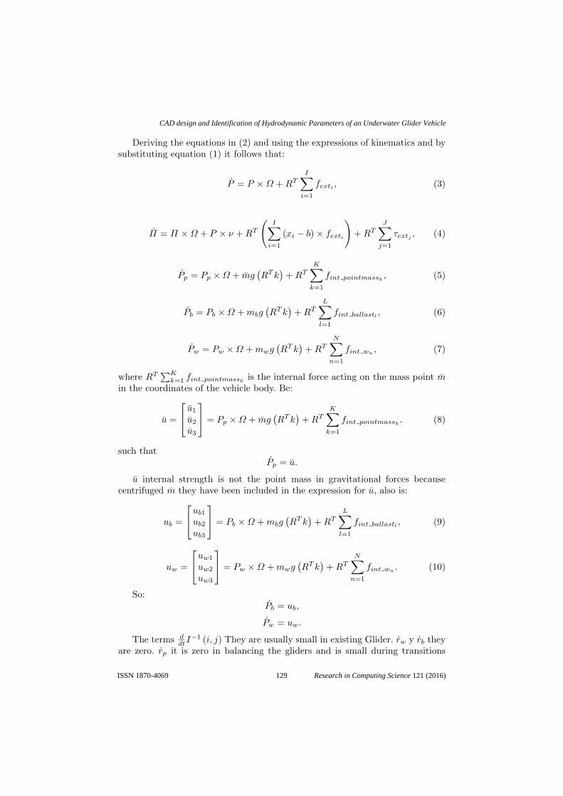
Gliders geometry is important for propulsion and maneuverability factor atdifferent speeds. One of the most common ways in Gliders is torpedo-shapedconsisting of a cylindrical body with its conical or spherical tips to simplifyidentification of the hydrodynamic parameters [11]. Accordingly, the geometryof the vehicle UPPGlider presented in this paper it is cylindrical, with a diameterof 15.4 cm and a length of 90 cm, see Figure 2. Based on the design of the vehicleand in order to simplify the mathematical model of UPPGlider, Assuming thatthe vehicle is moving at low speed, that is 0.25 m/s.
Fig. 2: UPPGlider: CAD design of the underwater vehicle.
Immersion and emersion (offset from the axis ZI) vehicle is generated bychanging its buoyancy ballast tank, while the displacement in the plane XI , YIis produced by the wings, the orientation of the vehicle and changing buoyancy[3]. The angular position roll (φ) remains close to zero due to the location of the
126
Jorge Díaz Moreno, Reynaldo Ortíz Pérez, Eduardo Campos Mercado, Luis Fidel Cerecero Natale
Research in Computing Science 121 (2016) ISSN 1870-4069

center of buoyancy and the center of gravity of the vehicle, the side wings helpthe damping roll; while the rotational movement pitch (θ) It is produced by theeffect of a moving mass and rotation yaw (ψ) It is governed by a rudder that islocated in the tail of the vehicle [2].
The embedded system consists of a computer 2.9GHz Intel Core i7-3520M,8GB of RAM, Windows 8.1 operating system and Visual Studio C ++ 2010 toprogram the control strategy. Measurements of the inertial unit and the pressuresensor are performed with a USB-I2C interface connected directly to the PC.The main characteristics of the vehicle are described in Table 1.
Table 1: Main features of the UUP Glider.
Dough 15 kgBuoyancy 9 NDimensions 90 cm (l) x 15.4 cm (w) x 15.4 cm (h)Operating depth 100mOperating Voltage 14VComputer NUC intel core i7 - 2.9GHz
Windows 8.1 Professional 64 bitsMicrosoft Visual C++ 2010
3 Mathematical Model
Fig. 3: Definition of mass of the Glider. [5]
The vehicle is modeled as a rigid body immersed in a fluid with fixed wings andtail, with the particularity that the total vehicle mass mv, is the sum of the massof the hull mh, calibration mass mw, the moving mass m and mass ballast tankmb; whose location with respect to the coordinate system fixed to the vehiclebody, is described by the vectors rh = 0 , rw, rp y rb respectively, as shown in
127
CAD design and Identification of Hydrodynamic Parameters of an Underwater Glider Vehicle
Research in Computing Science 121 (2016)ISSN 1870-4069

Figure 3. It is noteworthy that the mass ballast tank is variable (mb) but theirposition is constant, whereas the moving mass (m) It is constant but is variableposition.
To describe the force produced by the buoyancy has to the mass of the fluiddisplaced by the vehicle is denoted by m. Consequently, the net buoyancy isdefined as: m0 = mv −m so the vehicle has positive buoyancy if m0 > 0.
The equations describing the dynamics of Glider are obtained starting in themomentum, which you have to p It represents the moment of translation of thevehicle and the fluid and π the angular momentum, momentum both expressedrespect to the inertial coordinate system. In the case of translational momentumis must pp It represents the total momentum of the moving mass m, pb theyrepresent the momentum of the mass of ballast tank mb and pw describes themomentum of the mass mw. Considering the above and Newton’s laws we have:
p =I∑i=1
fexti ,
π =I∑i=1
(xi × fexti) +J∑j=1
τextj ,
pp = mgk +K∑k=1
fint pointmassk ,
pb = mbgk +L∑l=1
fint ballastl ,
pw = mwgk +N∑n=1
fint wn ,
(1)
where k is the unit vector in the direction of gravity, fexti an external force isapplied to the system and τextj It is an external torque. The vector xi The vectoris the location of the application point of force fexti with respect to the inertialcoordinate system. These external forces and torques include those due to gravityand buoyancy; however, gravity is explicitly included in the last three equationsbecause it is the only force acting on the three masses. The force fint pointmasskis applied from the vehicle body to the mobile hub, it will be used as a controlinput. The forces fint ballastl y fwn
are the forces applied from the vehicle bodyto the ballast system and mass calibration respectively.
In order to obtain the representation of the mathematical model with respectto the coordinate system fixed in the vehicle, it has to P It represents themomentum of the vehicle and Π the angular momentum, both expressed inthe coordinate system of the vehicle. The momentum of the moving mass isrepresented by Pp,on the other hand; Pb y Pw They represent the momentum ofthe mass of the ballast tank and the mass calibration of the vehicle respectively.From the above it has the following expression:
p = RP,π = RΠ + b× p,pp = RPp,pb = RPb,pw = RPw.
(2)
128
Jorge Díaz Moreno, Reynaldo Ortíz Pérez, Eduardo Campos Mercado, Luis Fidel Cerecero Natale
Research in Computing Science 121 (2016) ISSN 1870-4069
Deriving the equations in (2) and using the expressions of kinematics and bysubstituting equation (1) it follows that:
P = P ×Ω +RTI∑i=1
fexti , (3)
Π = Π ×Ω + P × ν +RT
(I∑i=1
(xi − b) × fexti
)+RT
J∑j=1
τextj , (4)
Pp = Pp ×Ω + mg(RT k
)+RT
K∑k=1
fint pointmassk , (5)
Pb = Pb ×Ω +mbg(RT k
)+RT
L∑l=1
fint ballastl , (6)
Pw = Pw ×Ω +mwg(RT k
)+RT
N∑n=1
fint wn , (7)
where RT∑Kk=1 fint pointmassk is the internal force acting on the mass point m
in the coordinates of the vehicle body. Be:
u =
u1
u2
u3
= Pp ×Ω + mg(RT k
)+RT
K∑k=1
fint pointmassk . (8)
such thatPp = u.
u internal strength is not the point mass in gravitational forces becausecentrifuged m they have been included in the expression for u, also is:
ub =
ub1ub2ub3
= Pb ×Ω +mbg(RT k
)+RT
L∑l=1
fint ballastl , (9)
uw =
uw1
uw2
uw3
= Pw ×Ω +mwg(RT k
)+RT
N∑n=1
fint wn. (10)
So:Pb = ub,
Pw = uw.
The terms ddtI
−1 (i, j) They are usually small in existing Glider. rw y rb theyare zero. rp it is zero in balancing the gliders and is small during transitions
129
CAD design and Identification of Hydrodynamic Parameters of an Underwater Glider Vehicle
Research in Computing Science 121 (2016)ISSN 1870-4069
between equilibrium (due to the speed of actuators Glider). The magnitudes ofthe elements J generally they are large compared with the elements of rp, rby rw. The terms may be significant in designs Gliders very large or very smallactuators or those with fast internal mass.
The full equations of motion for a submarine Glider in three dimensionalspace are:
R
b
ΩυrprbrwPpPbPwmb
=
RΩRυJ−1TM−1F
1mPp − υ −Ω × rp1mbPb − υ −Ω × rb
1mw
Pw − υ −Ω × rwuubuw
uballast rate
, (11)
where:
T = (JΩ + rpPp + rbPb + rwPw) ×Ω + (Mv × v)+ (Ω × rp) × Pp + (Ω × rb) × Pb + (Ω × rw) × Pw + (mrp +mbrb +mw rw) gRT k+Text − rpu− (rbub + rwuw),
F = (Mv + Pp + Pb + Pw) ×Ω +m0gRT k + Fext − u− (ub + uw).
Thus,
Fext = RT∑fexti ,
Text = RT∑
(xi − b) × fexti +RT∑τextj ,
where xi is the point, where the inertial system fexti acts represents externalforces and moments including lift, drag and hydrodynamic moments associatedwith the system of the vehicle.
u is a force control m, and ub and uw are internal forces in the masses mb
and mw. They will be restoring forces when the masses are fixed in one place.
4 Hydrodynamic Parameters Identification
When a body immersed in a fluid moves; a quantity of fluid is moved along withit (added mass), this amount of fluid will depend on the geometry of the vehicle[5], Likewise; There forces affecting movement direction in x,y,z (Hydrodynamicforces) and moments affecting the orientation roll (φ), pitch (θ), and yaw (ψ)(hydrodynamic moments) [4].All measurements are made based on the center ofbuoyancy, because at this point systems coordinates fixed to the vehicle and thereference coordinate system are located fluid.
130
Jorge Díaz Moreno, Reynaldo Ortíz Pérez, Eduardo Campos Mercado, Luis Fidel Cerecero Natale
Research in Computing Science 121 (2016) ISSN 1870-4069
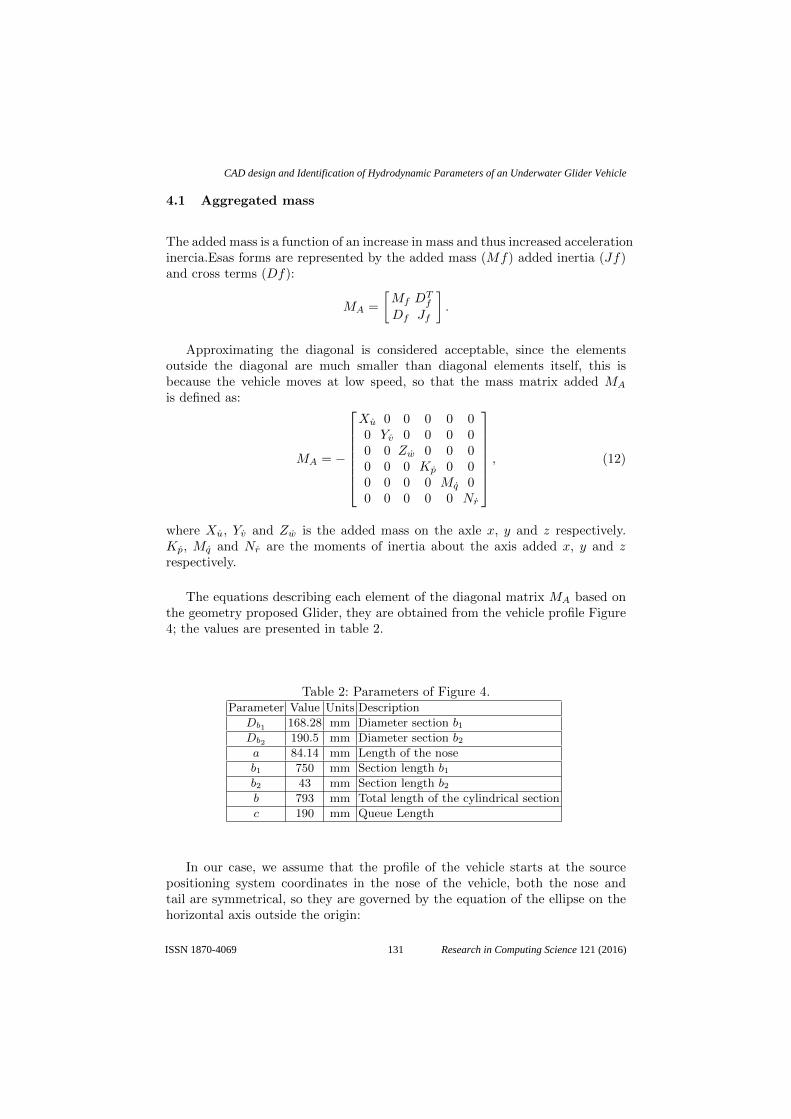
4.1 Aggregated mass
The added mass is a function of an increase in mass and thus increased accelerationinercia.Esas forms are represented by the added mass (Mf) added inertia (Jf)and cross terms (Df):
MA =
[Mf D
Tf
Df Jf
].
Approximating the diagonal is considered acceptable, since the elementsoutside the diagonal are much smaller than diagonal elements itself, this isbecause the vehicle moves at low speed, so that the mass matrix added MA
is defined as:
MA = −
Xu 0 0 0 0 00 Yv 0 0 0 00 0 Zw 0 0 00 0 0 Kp 0 00 0 0 0 Mq 00 0 0 0 0 Nr
, (12)
where Xu, Yv and Zw is the added mass on the axle x, y and z respectively.Kp, Mq and Nr are the moments of inertia about the axis added x, y and zrespectively.
The equations describing each element of the diagonal matrix MA based onthe geometry proposed Glider, they are obtained from the vehicle profile Figure4; the values are presented in table 2.
Table 2: Parameters of Figure 4.Parameter Value Units Description
Db1 168.28 mm Diameter section b1Db2 190.5 mm Diameter section b2a 84.14 mm Length of the nose
b1 750 mm Section length b1b2 43 mm Section length b2b 793 mm Total length of the cylindrical section
c 190 mm Queue Length
In our case, we assume that the profile of the vehicle starts at the sourcepositioning system coordinates in the nose of the vehicle, both the nose andtail are symmetrical, so they are governed by the equation of the ellipse on thehorizontal axis outside the origin:
131
CAD design and Identification of Hydrodynamic Parameters of an Underwater Glider Vehicle
Research in Computing Science 121 (2016)ISSN 1870-4069
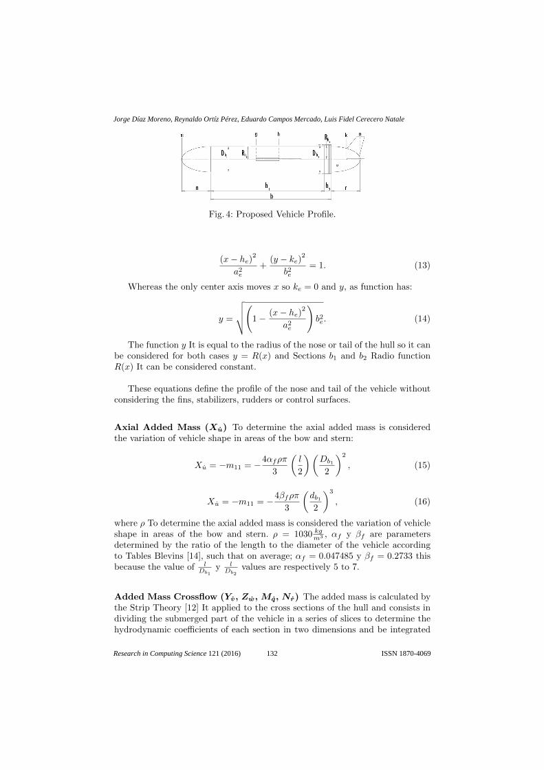
Fig. 4: Proposed Vehicle Profile.
(x− he)2
a2e
+(y − ke)
2
b2e= 1. (13)
Whereas the only center axis moves x so ke = 0 and y, as function has:
y =
√√√√(1 − (x− he)2
a2e
)b2e. (14)
The function y It is equal to the radius of the nose or tail of the hull so it canbe considered for both cases y = R(x) and Sections b1 and b2 Radio functionR(x) It can be considered constant.
These equations define the profile of the nose and tail of the vehicle withoutconsidering the fins, stabilizers, rudders or control surfaces.
Axial Added Mass (Xu) To determine the axial added mass is consideredthe variation of vehicle shape in areas of the bow and stern:
Xu = −m11 = −4αfρπ
3
(l
2
)(Db1
2
)2
, (15)
Xu = −m11 = −4βfρπ
3
(db12
)3
, (16)
where ρ To determine the axial added mass is considered the variation of vehicleshape in areas of the bow and stern. ρ = 1030 kg
m3 , αf y βf are parametersdetermined by the ratio of the length to the diameter of the vehicle accordingto Tables Blevins [14], such that on average; αf = 0.047485 y βf = 0.2733 thisbecause the value of l
Db1y lDb2
values are respectively 5 to 7.
Added Mass Crossflow (Yv, Zw, Mq, Nr) The added mass is calculated bythe Strip Theory [12] It applied to the cross sections of the hull and consists individing the submerged part of the vehicle in a series of slices to determine thehydrodynamic coefficients of each section in two dimensions and be integrated
132
Jorge Díaz Moreno, Reynaldo Ortíz Pérez, Eduardo Campos Mercado, Luis Fidel Cerecero Natale
Research in Computing Science 121 (2016) ISSN 1870-4069
along the length of the body finally obtain the coefficients in three dimensions.Aggregate per unit length of a single cylindrical mass segment is given by:
ma (x) = πρR (x)2, (17)
where ρ It is the density of the surrounding fluid and R (x) is the radius of thehull as a function of axial position. The aggregate mass finned a circle is givenby:
maf = πρ
(a2aleta −R (x)
2+R (x)
4
a2aleta
), (18)
where aaleta It is the maximum height of the fin measured from the axis of theellipsoid. By integrating the equations 17 and 18 the length of the vehicle isreached:
Yv = −∫ gnima (x) dx−
∫ hgmaf (x) dx−
−∫ khma (x) dx−
∫ cfkmaf (x) dx,
Zw = −∫ cfnima (x) dx,
Mq = −∫ gnix2ma (x) dx−
∫ hgx2maf (x) dx−
−∫ khx2ma (x) dx−
∫ cfkx2maf (x) dx,
Nr = −∫ cfnix2ma (x) dx.
(19)
Due to Added Mass Balance (Kp) To estimate the added mass due torolling, only it considered the section of the hull containing the fins [12]:
Kp = −∫ h
g
2
πρa4aletadx. (20)
Substituting measures and functions, parameters are obtained aggregate massMA.
Table 3: Results of the added mass.Parameter Value Units
Xu -0.7738890384 kg
Yv -60.49746284 kg
Zw -22.49920646 kg
Kp -0.8306898369 kg·m2
rad
Mq -15.85575167 kg·m2
rad
Nr -7.843744090 kg·m2
rad
4.2 Aerodynamic Forces and Moments
The forces Fhydro and aerodynamic momentsMhydro viscous effects appear waterduring movement of the glider and are usually expressed under the fluid as [14]:
133
CAD design and Identification of Hydrodynamic Parameters of an Underwater Glider Vehicle
Research in Computing Science 121 (2016)ISSN 1870-4069
Fhydro =
−DSF−L
=
(KD0 +KDα2)V 2
KββV2
(KL0 +Kαα)V 2
, (21)
Mhydro =
TDL1
TDL2
TDL3
=
(KMRβ +Kpp)V2
(KM0 +KMα+Kqq)V2
(KMY β +Krr)V2
, (22)
where: KD0, KD are coefficients of the drag force (x) in D with respect to V 2,α2V 2.Kβ It is the coefficient of force (y) side L with respect to βV 2.KL0, Kα are coefficients of force (z) supporting L with respect to V 2, αV 2.KMR, Kp are coefficients roll moment TDL1 with respect to βV 2, pV 2.KM0, KM , Kq are coefficients pitch moment TDL2 with respect to V 2, αV 2,qV 2.KMY , Kr coefficients are time yaw TDL3 with respect to βV 2, rV 2.
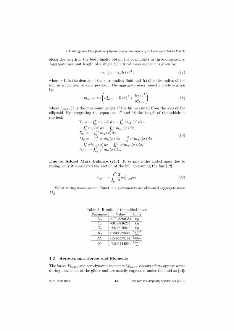
Analysis of the Data To determine the values of the coefficients of thehydrodynamic forces and moments has been used data collection through variousfluid simulations with CFD module called SolidWorks Flow Simulation. Thesimulations are to be changing angles of attack αand sideslip β, where:
α = tan−1
(V3
V1
),
β = tan−1
(V2√
V 21 + V 2
2 + V 23
).
The coordinate system flow shown in Figure 5 together with the angles ofattack α and sideslip βplus speeds on each axis.
Fig. 5: Vehicle reference systems and fluid and Fluid direction in Flow Simulationrespectively.
134
Jorge Díaz Moreno, Reynaldo Ortíz Pérez, Eduardo Campos Mercado, Luis Fidel Cerecero Natale
Research in Computing Science 121 (2016) ISSN 1870-4069
Glider speed is represented transforming the speed displayed in the fluidsystem attached to the body system as:V1
V2
V3
= RWB ×
V00
=
V cosα cosβV sinβ
V cosβ sinα
.To determine the values of the coefficients of the hydrodynamic forces in
these simulations is configured that the total speed that will move the glider isV =
√V 2
1 + V 22 + V 2
3 = 0.5m/s, varying angles α and β It is to vary the velocitycomponents of the fluid and then let the software determine the hydrodynamicforces.
The table 4 shows the values of the obtained coefficients.
Table 4: Values of the constants of aerodynamic forces and moments.Parameter Value Units
KD0 5.04 kg/m
KD -4.2863 kg/m/rad2
Kβ -42.3403 kg/m/rad
KL0 0.7 kg/m
Kα 95.3556 kg/m/rad
KMR -16.7381 kg/rad
Kp -174.3244 kg s/rad
KM0 0.392 kg
KM -40.2293 kg/rad
Kq -117.804 kg s/rad
KMY 20.794 kg/rad
Kr -41.2834 kg s/rad
5 Simulation and Results
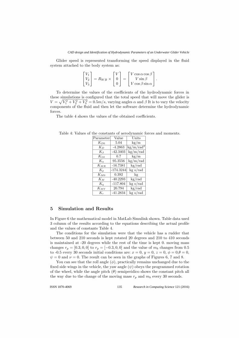
In Figure 6 the mathematical model in MatLab Simulink shown. Table data used3 column of the results according to the equations describing the actual profileand the values of constants Table 4.
The conditions for the simulation were that the vehicle has a rudder thatbetween 50 and 210 seconds is kept rotated 20 degrees and 210 to 410 secondsis maintained at -20 degrees while the rest of the time is kept 0. moving masschanges rp = [0.3, 0, 0] to rp = [−0.3, 0, 0] and the value of mb changes from 0.5to -0.5 every 30 seconds initial conditions are: x = 0, y = 0, z = 0, φ = 0,θ = 0,ψ = 0 and ν = 0. The result can be seen in the graphs of Figures 6, 7 and 8.
You can see that the roll angle (φ), practically remains unchanged due to thefixed side wings in the vehicle, the yaw angle (ψ) obeys the programmed rotationof the wheel, while the angle pitch (θ) semiperidico shows the constant pitch allthe way due to the change of the moving mass rp and mb every 30 seconds.
135
CAD design and Identification of Hydrodynamic Parameters of an Underwater Glider Vehicle
Research in Computing Science 121 (2016)ISSN 1870-4069
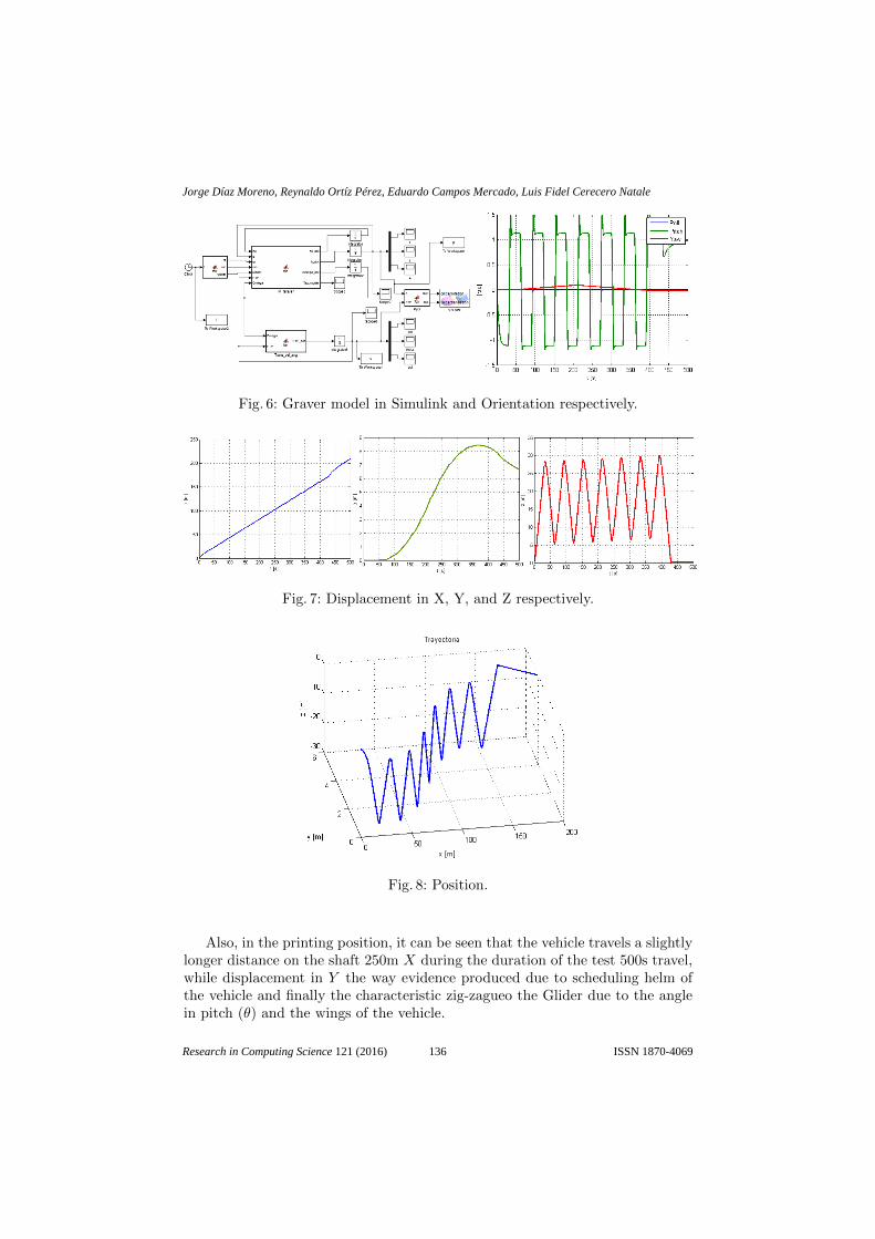
Fig. 6: Graver model in Simulink and Orientation respectively.
Fig. 7: Displacement in X, Y, and Z respectively.
Fig. 8: Position.
Also, in the printing position, it can be seen that the vehicle travels a slightlylonger distance on the shaft 250m X during the duration of the test 500s travel,while displacement in Y the way evidence produced due to scheduling helm ofthe vehicle and finally the characteristic zig-zagueo the Glider due to the anglein pitch (θ) and the wings of the vehicle.
136
Jorge Díaz Moreno, Reynaldo Ortíz Pérez, Eduardo Campos Mercado, Luis Fidel Cerecero Natale
Research in Computing Science 121 (2016) ISSN 1870-4069

Acknowledgments. This work was partially supported by a CONACyT CVU:637204.
References
1. Akyildiz, I.F., Pompili, D., Melodia, R.: Underwater acoustic sensor networks:research challenges. Science Direct (2005)
2. Bender, A., Matthew, D., Lee, A., Williams, S.B.: Analysis of an autonomousunderwater glider. Australian Centre for Field Robotics (2006)
3. Campos, E., J.Torres, S.Mondi, Lozano, R.: Deep control using artificial visionwith time-delay of an auv. 9th International Conference on Electrical Engineering,Computing Science and Automatic Control (2012)
4. Fossen, T.I.: Marine control systems guidance, navigation, and control of ships,rigs and underwater vehicles (2002)
5. Graver, J.G.: Underwater gliders: Dynamics, control and design (2005)6. Jun, B.H., Park, J.Y., Lee, F.Y., Lee, P.M., Lee, C.M., Kin, K., Lim, Y.K., Oh,
J.H.: Development of the auv ’isimi’ and a free running test in an ocean engieeringbasin. Ocean Engineering (2009)
7. Liang, X., Zhang, J., Qin, Y., Yang, H.: Dynamic modeling and onputer simulationfor autonomous underwater vehicles with fins. Ocean Engineering (2012)
8. Mercado, E.C.: Design, modelling and control of auv’s using artificial vision (2014)9. Naomi Ehrich Leonard, J.G.G.: Model-based feedback control of autonomous
underwater giders. IEE Journal of Oceanic Engineering, Vol. 26, No 4 (2001)10. NigelCross: GEngeneering Design Methods Strategies for Product Design (2000)11. Pellicer, A.G.: Estimacin de los coeficientes hidrodinmicos de vehculos autnomos
submarionos mediante CFD12. Prestero, T.: Verification of a six-degree of freedom simulation model for the remus
autonomus underwater vehicle13. Smith, S.N., Smith, S.L., Rus, D., ad Burton H. Jones, M.S., Sukhatme, G.S.:
Persistent ocean monitoring with underwater gliders. Open Access Articles (2011)14. Zhang, S., Yu, J., Zhang, A., Zhang, F.: Spilaring motion of underwater gliders:
Modeling, analysis, and experimental results. Ocean Engineering (2012)
137
CAD design and Identification of Hydrodynamic Parameters of an Underwater Glider Vehicle
Research in Computing Science 121 (2016)ISSN 1870-4069