cable-stayed bridges of prestressed concrete journal/1973/january... · discusses prestressed...
TRANSCRIPT

CABLE-STAYED BRIDGES OFPRESTRESSED CONCRETEWalter Podolny, Jr.Bridge DivisionFederal Highway AdministrationU.S. Department of TransportationWashington, D.C.
Discusses prestressed concrete cable-stayed bridgestructures. Although most cable-stayed bridgeshave been of steel construction, a few have beenmade of prestressed concrete. This type of structureis presented on a case-study basis with theintent of encouraging designers to consider thefeasibility of using this type of structure whichin some instances might be a more appropriate choice.
The concept of supporting a bridgedeck by using one or more inclinedstays was proposed in 1784 by C. J.Loscher, a German carpenter in Fri-bourg. It was conceived as a timberbridge consisting of timber stays at-tached to a timber tower.1-4
Unfortunately, during the birth ofthe cable-stayed system, the engineersof that period were unable to calculatethe forces in the stays nor understand orcontrol the equilibrium of these highlyindeterminate systems. Unsuitable ma-terials such as timber, round bars orchains were used for stays. The staysconstructed in this manner were, there-fore, of low strength material and couldnot be fully tensioned. In a slack con-dition they required substantial defor-mation of the deck before they couldparticipate in taking the tensile load forwhich they were intended.
The first modern steel cable-stayedbridge, the Stromsund Bridge, wascompleted in Sweden in 1955 by aGerman contractor. Although the cable-stayed Tempul Aqueduct in Spain, de-signed by Torroja, was completed in1925, the first modern prestressed con-crete cable-stayed bridge structure wasMorandi's Lake Maracaibo Bridge inVenezuela, completed in 1962.
Lake Maracaibo Bridge,Venezuela (The GeneralRafael Urdaneta Bridge)
This reinforced and prestressed con-crete bridge structure ranks as one ofthe longest in the world. The primecontractor was Maracaibo Bridge JointVenture comprised of PrecomprimidoC.A., Caracas, Venezuela and JuliusBerger A.G., Wiesbaden, Germany. The
68

designer was Prof. Riccardo Morandi ofRome. The structural analysis and de-tailed plans were prepared by theMaracaibo Bridge Joint Venture inconjunction with Prof. Morandi.
With the one exception, all 12 de-signs submitted in the competition ad-vocated a steel superstructure. The rea-sons for the selection of the MaracaiboBridge Joint Venture design by the gov-ernment commission were given as fol-lows:5
1. Reduction of maintenance costs asa result of the climate conditionsexisting at the site.
2. The aesthetics of the design.3. The greater use of local materials
and therefore less foreign ex-change expended for importedmaterials.
4. Greater use of local engineeringtalent and labor.
Fig. 1. Lake Maracaibo Bridge
The total length of this structure is5.4 miles (8.7 km). The five main nav-igation openings consist of prestressedconcrete cantilevered cable-stayedstructures with suspended spans havinga total 771 ft (235 m) span (see Fig.1). Navigation requirements stipulated
Fig. 2. Main span tower and X frames
PCI Journal/January-February 1973ҟ 69

Fig. 3. Pier caps with X frames
a horizontal clearance of 656.2 ft (200m) and a vertical clearance of 147.6 ft(45 m). To preclude any possible dam-age as a result of unequal foundationsettlement or earthquake forces, thecentral spans had to be statically deter-minate. Thus, a main span is divided in-to cantilever sections with a simply sup-ported suspended center portion.
The pier foundation width of 113.5ft (34.6 m), Fig. 2, was determinedfrom transferring longitudinal bendingmoments, resulting from the placing ofthe suspended span and from unsym-metrical traffic loads. With a 656.2 ft(200 m) clear span requirement and a150.9 ft (46 m) suspended span, the
48.55 m
Concentricprestress
Workiplats
Service gcantileve
Fig. 4. Pier cap of a main span and service girder
70

cantilever arm extends 252.6 ft (77 m)beyond the pier foundation. To avoidthe large depth associated with a canti-lever of this dimension, cable stays wereused as a supporting system from the303.5 ft (92.5 m) high towers. Anyother system of support would have re-quired deeper girders and thus wouldhave changed the roadway elevation orinfringed on the required navigationalclearance.
The cantilever span is supported onX frames while the cable stays are sup-ported on two A frames with a portalmember at the top. There is no connec-tion anywhere between the X and Aframes (see Fig. 2). The continuouscantilever girder is a three-cell box-girder 16.4 ft (5 m) deep by 46.7 ft(14.22 m) wide. An axial prestressforce is induced into the girder as a re-sult of the horizontal component ofcable force. Thus, for the most part,only conventional reinforcement is re-quired. Additional prestressing tendonswere required for negative momentabove the X frame support andthe transverse cable-stay anchoragebeams.5
The pier cap consists of the three cellbox girder with the X frames continuedup into the girder to act as transversediaphragms (see Figs. 3 and 4) . Aftercompletion of the pier, service girdersare raised into position to be used inthe construction of the cantilever arm.Due to the additional moment, pro-duced during this construction stage bythe service girder and weight of thecantilever arm, additional concentricprestressing was required in the piercap (see Fig. 4). To avoid overstressingof the X frames during this operation,temporary horizontal ties were installedand tensioned by hydraulic jacks (seeFigs. 4 and 5).
In the construction of the cantilever
Fig. 5. Brace members bear against Xframes after being tensioned by hy-
draulic jacks
were supported at one end by the com-pleted pier cap and at the other end byauxiliary piers and foundations asshown in Fig. 6.
The anchorages for the cable staysare located in a 73.8 ft (22.5 m) longprestressed inclined transverse girder.The reinforcing cages for these mem-bers were fabricated on shore in a posi-tion corresponding to the inclination ofthe cables. They weighed 60 tons andcontained 70 prestressing tendons (seeFig. 7). The cable stays are housed inthick walled steel pipes (see Fig. 8),
arms, special steel trusses (service gird- Fig. 6. Placing service girders for form-ers) were used for formwork. They ing cantilever girders
PCI Journal/January-February 1973ҟ 71

Fig. 7. Fabrication of anchorage beam
Fig. 8. Housing for cable stays
Fig. 9. Erection of reinforcing cagefor prestressed transverse anchoring
girder
which were welded to steel plates attheir extremity. A special steel spreaderbeam was used to erect the fabricatedcage in its proper orientation as shownin Fig. 9.
The suspended spans were composedof four prestressed T sections (see Fig.10).
Polcevera Viaduct,Genoa, Italy
This structure was also designed byMorandi and is similar in design andappearance to the Maracaibo Bridge(see Fig. 11). It is a high level viaduct3600 ft (1100 m) long with the road-way at an elevation of 181 ft (55 m)above the terrain. The three maincable-stayed spans have lengths of 664,689, and 460 ft (200, 210, and 140m). 6 The bridge carries the Genoa-Savona motorway over an area com-posed of railway yards, roads, industrialplants, and the "Polcevera" creek. Thetop of the cable-stayed supporting Aframe is 139.5 ft (42.5 m) above theroadway elevation. As in the Maracaibostructure the A frame has a longitudinalgirder at the roadway level and a trans-verse girder at the top. The deck girderin this structure is a five-cell box girder.Center suspended girders are 118 ft(36 m) long. The transverse cable-stayanchorage girders in this structure arebox girders requiring that the cablestays divide above the roadway andanchor through the webs of the anchor-age girder. The cable stays are com-posed of pretensioned high-tensile steelstrands encased in a protective concreteshell.6
Wadi Kuf Bridge, LibyaThe Wadi Kuf Bridge (see Fig. 12)
is another Morandi design with threespans. The structure has a 925 ft (280m) center span, and 320 ft (98 m) endspans with a total length of 1565 ft
72

(475 m). The familiar A frame towersare 459 and 400 ft (140 and 122 m)high with the deck clearing the valleyat its lowest point by 597 ft (182 m).The superstructure is a single-cell boxgirder of variable depth with cantileverflanges forming a 42.7-ft (13 m) deck.?
Because of the height and difficultterrain the contractor used travelingforms to construct the box girder anddeck in a balanced cantilever construc-tion. Temporary cable stays were usedto support the cantilever arms duringconstruction as they progressed in bothdirections from the tower until the per-manent stays were installed.
The simply supported "drop-in" cen-ter portion of the span consisted ofthree 180 ft (55 m) long double-Tbeams weighing approximately 220 tonseach.s
Magliana ViaductThis is still another example of Mor-
andi's structures. This particular bridgecarries the roadway of the Rome-Fiumi-cino Airport over a swamp area formedby a bend of the Tiber river. The sitewas unavoidable because of the proxim-ity of the Rome to Pisa railway line.This structure, as shown in Fig. 13, hasa single portal type tower and a totallength of 652 ft (].98.6 m) with 476and 176 ft (145 and 53.6 m) spans.The 476-ft (145 m) span is composedof a 206 ft (63 m) suspended span anda 269 ft (82 m) cantilever span whichis supported by a forestay at 226 ft (69m) from the tower. The structure is fur-ther complicated in that the road-way at the site of the structure has ahorizontal curve of 1558 ft (475 m)radius. The seven-cell box girder canti-lever deck is 70.5 ft (21.5 m) wide plusthe variable overhang on each side tomake up a 79 ft (24.2 m) roadwaywidth. The suspended span is com-posed of eight prestressed T-beams.8
Fig. 10. Erection of suspended girder
Fig. 11. Polcevera Creek Bridge
Fig. 12. Wadi Kufi Bridge
In this structure Morandi abandonedthe fixity achieved by the X shapedpiers and A frame towers which was histrademark in his previous structuresand resorted to a fully-articulated struc-ture. The tower is hinged at its base.Also, the cantilever span containshinges at the tower and the anchor
PCI Journal/January-February 1973 73

20.0 m
30.
I _'37 m
LONGITUDINAL SECTION
Fig. 13. Magliana Viaduct
span. The hinges are large radius steellined concrete surfaces that extend thefull width of the deck (see Fig. 14).8
The transverse stay anchorage beamis a box section that is 26 ft (8 m) deepand 8.8 ft (2.7 m) wide and similar tothe Polcevera viaduct. The fore stay isdivided to accommodate the anchorageinto each web (see Fig. 15). Prestress-
ing for the anchorage beam consists of76 cables of sixteen 0.2 in. (5 mm)diameter wires (see Fig. 16).
The use of parallel prestressing wirein the stays was a new innovation onthis project. Fig. 17 shows a closeup ofthe cable-stay tendons at the juncturewith the prestressing tendons in theanchorage girder.8
74

Fig. 14. Steel lined hinge
Danish Great Belt BridgeCompetition
A third prize winner in this competi-tion was the Morandi style design pro-posed by the English consulting firm ofWhite, Young, and Partners (see Fig.18) . Design requirements were forthree lanes of road traffic in each direc-tion and a single rail traffic in each di-rection. Rail traffic was based on speedsof up to 100 mph. Navigation require-ments stipulated a bridge deck heightof 220 ft (67 m) above water level anda clear width of 1130 ft (345 m).9
The deck is envisioned as two paral-lel single-cell box girders (see Fig. 19),where the rail traffic would be carriedinside the box on the bottom flange andthe road traffic would be carried on thesurface of the top flange. The box gird-er will probably have a 23.5 ft (7.2 m)depth and a 27.75 ft (8.45 m) widthwith the top flange cantilevered out 12ft (3.675 m) on each side.'°
The piers are planned to be cast-in-place and capable of carrying the deckunits. The deck units will be precast atvarious locations on shore and floatedinto position for erection. The maxi-mum weight of a box unit is estimatedto be 2200 tons. The bridge is designedusing only reinforced and prestressedconcrete.
This structure is notable in that the
Fig. 15. Fore stay
Fig. 16. Prestress tendons in anchoragebeam
Fig. 17. Juncture of stay with anchor-age beam
PCI Journal/January-February 1973 75
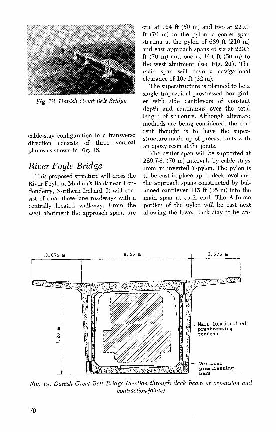
Fig. 18. Danish Great Belt Bridge
cable-stay configuration in a transversedirection consists of three verticalplanes as shown in Fig. 18.
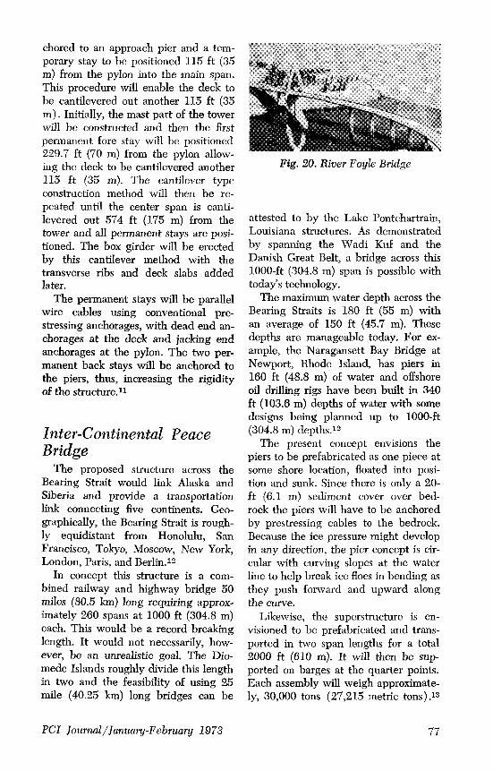
River Foyle BridgeThis proposed structure will cross the
River Foyle at Madam's Bank near Lon-donderry, Northern Ireland. It will con-sist of dual three-lane roadways with acentrally located walkway. From thewest abutment the approach spans are
one at 164 ft (50 m) and two at 229.7ft (70 in) to the pylon, a center spanstarting at the pylon of 689 ft (210 m)and east approach spans of six at 229.7ft (70 m) and one at 164 ft (50 m) tothe west abutment (see Fig. 20) . Themain span will have a navigationalclearance of 105 ft (32 m).
The superstructure is planned to be asingle trapezoidal prestressed box gird-er with side cantilevers of constantdepth and continuous over the totallength of structure. Although alternatemethods are being considered, the cur-rent thought is to have the super-structure made up of precast units withan epoxy resin at the joints.
The center span will be supported at229.7-ft (70 m) intervals by cable staysfrom an inverted Y-pylon. The pylon isto be cast in place up to deck level andthe approach spans constructed by bal-anced cantilever 115 ft (35 m) into themain span at each end. The A-frameportion of the pylon will be cast nextallowing the lower back stay to be an-
3.675 mḏ8.45 mḏ
3.675 m
ri Main longitudinalprestressing
o j j , tendons
Verticalprestressing
^..ḏ K*A i,'ḏbars
Fig. 19. Danish Great Belt Bridge (Section through deck beam at expansion andcontraction joints)
76
chored to an approach pier and a tem-porary stay to be positioned 115 ft (35m) from the pylon into the main span.This procedure will enable the deck tobe cantilevered out another 115 ft (35m) . Initially, the mast part of the towerwill be constructed and then the firstpermanent fore stay will be positioned229.7 ft (70 m) from the pylon allow-ing the deck to be cantilevered another115 ft (35 m). The cantilever typeconstruction method will then be re-peated until the center span is canti-levered out 574 ft (175 m) from thetower and all permanent stays are posi-tioned. The box girder will be erectedby this cantilever method with thetransverse ribs and deck slabs addedlater.
The permanent stays will be parallelwire cables using conventional pre-stressing anchorages, with dead end an-chorages at the deck and jacking endanchorages at the pylon. The two per-manent back stays will be anchored tothe piers, thus, increasing the rigidityof the structure."
Inter-Continental PeaceBridge
The proposed structure across theBearing Strait would link Alaska andSiberia and provide a transportationlink connecting five continents. Geo-graphically, the Bearing Strait is rough-ly equidistant from Honolulu, SanFrancisco, Tokyo, Moscow, New York,London, Paris, and Berlin.12
In concept this structure is a com-bined railway and highway bridge 50miles (80.5 km) long requiring approx-imately 260 spans at 1000 ft (304.8 m)each. This would be a record breakinglength. It would not necessarily, how-ever, be an unrealistic goal. The Dio-mede Islands roughly divide this lengthin two and the feasibility of using 25mile (40.25 km) long bridges can be
Fig. 20. River Foyle Bridge
attested to by the Lake Pontchartrain,Louisiana structures. As demonstratedby spanning the Wadi Kuf and theDanish Great Belt, a bridge across this1000-ft (304.8 m) span is possible withtoday's technology.
The maximum water depth across theBearing Straits is 180 ft (55 m) withan average of 150 ft (45.7 m). Thesedepths are manageable today. For ex-ample, the Naragansett Bay Bridge atNewport, Rhode Island, has piers in160 ft (48.8 m) of water and offshoreoil drilling rigs have been built in 340ft (103.6 m) depths of water with somedesigns being planned up to 1000-ft(304.8 m) depths.12
The present concept envisions thepiers to be prefabricated as one piece atsome shore location, floated into posi-tion and sunk. Since there is only a 20-ft (6.1 m) sediment cover over bed-rock the piers will have to be anchoredby prestressing cables to the bedrock.Because the ice pressure might developin any direction, the pier concept is cir-cular with curving slopes at the waterline to help break ice floes in bending asthey push forward and upward alongthe curve.
Likewise, the superstructure is en-visioned to be prefabricated and trans-ported in two span lengths for a total2000 ft (610 m). It will then be sup-ported on barges at the quarter points.Each assembly will weigh approximate-ly, 30,000 tons (27,215 metric tons) .13
PCI Journal/January-February 1973 77

Fig. 21. Inter-Continental Peace Bridge
An artist's rendering of one such con-cept, a cable-stayed structure, is illus-trated in Fig. 21.
Other structuresThe Soviet Union's largest cable-
stayed bridge is presently under con-struction over the Dnieper River atKiev (see Fig. 22) . The bridge has a984-ft (300 m) span and reportedlywill be of concrete construction. It isscheduled for completion in 1974.14,15
Amman and Whitney is constructinga bridge at Corrientes, Argentina, overthe River Parana. This bridge, whichhas a 837-ft (255 m) span, was sched-uled for completion in late 1972.
Morandi designed the twin Zarate-
Fig. 22. Dnieper River Bridge at Kiev
Brazo Largo rail-highway bridge overthe River Parana in Mesopotamia, Ar-gentina. This bridge has a 1116-ft (340m) span and was scheduled for com-pletion in 1972. It has a steel trussdeck and the superstructure is sup-ported on prestressed concrete pylons.
ConclusionWith today's advanced techniques of
prefabrication, post-tensioning, segmen-tal cantilever construction, and cable-stayed design and construction, pre-stressed concrete bridges spanning morethan 1000 ft (304.8 m) are possible.We have the technology; what is nowneeded is greater implementation.
AcknowledgmentsI wish to express my appreciation to
the following people and firms who havebeen of indispensable help in obtaining in-formation, publications, and photographs:Julius Berger, Bauboag Aktiengesellschaft,
Wiesbaden (Maracaibo Bridge).Prof. Morandi, Rome (Wadi Kuf).Dr. Gaetano Bologna, l'Industria Italiana
del Cemento, Rome (Magliana Viaduct).White, Young, and Partners, London
(Danish Great Belt Bridge).Civil Engineering and Public Works Re-
view, London (River Foyle Bridge).Prof. T. Y. Lin (Inter-Continental Peace
Bridge)Juhani Virola, Finland (Dnieper River
Bridge).
References1. Feige, A., "The Evolution of Ger-
man Cable-Stayed Bridges—AnOverall Survey," Acier-Stahl-Stahl(English version), No. 12, Decem-ber 1966. (Reprinted in AISC En-gineering Journal, July 1967.)
2. Thul, H., "Cable-Stayed Bridges inGermany," Proceedings, Confer-ence on Structural Steelwork, In-stitution of Civil Engineers, Sep-tember 26 to 28, 1966, London,England.
78

3. Podolny, Walter, Jr., "Static Analy-sis of Cable-Stayed Bridges," PhDThesis, University of Pittsburgh,1971.
4. Podolny, Walter, Jr., and Fleming,J. F., "Historical Development ofCable-Stayed Bridges," Journal ofthe Structural Division, ASCE, Vol.98, No. ST 9, Proceedings Paper9201, September, 1972.
5. Anon., The Bridge Spanning LakeMaracaibo in Venezuela, Wies-baden, Berlin: Bauverlag GmbH.,1963.
6. Morrandi, Riccardo, "Some Typesof Tied Bridges in Prestressed Con-crete," First International Sympo-sium, Concrete Bridge Design, ACIPublication SP-23, Paper SP 23-25,American Concrete Institute, De-troit 1969, pp. 447-465.
7. Anon., "Longest Concrete Cable-Stayed Span Cantilevered OverTough Terrain," EngineeringNews-Record, July 15, 1971.
8. Morandi, Riccardo, "Il Viadottodell Ansa della Magliana per laAutostrada Roma-Aeroporto diFiumicino," L'Industria Italiana delCeinento (Rome), Anno XXXVIII,March 1968.
9. Private Correspondence withWhite, Young, and Partners.
10. Anon., "Morandi—Style Design Al-lows Constant Suspended Spans,"The Consulting Engineer, March,1967.
11. Anon., "River Foyle Bridge," CivilEngineering and Public Works Re-view (London), Vol. 66, No. 780,
July 1971.12. Anon., Intercontinental Peace
Bridge, ICPB, Inc., San Francisco,1970.
13. Lin, T. Y.; Kulka, F.; and Yang,Y. C., "Basic Design Concepts ForLong Span Structures," MeetingPreprint 1727, ASCE NationalStructural Engineering Meeting,Cleveland, Ohio, April 24-28,1972.
14. Virola, Juhani, Private Correspon-dence.
15. Virola, Juhani, "USSR's LargestCable-Stayed Bridge Under Con-struction at Kiev," Tiemies, No. 4,1971 (in Finnish).
Supplementary references16. Tang, Man-Chung, "Analysis of
Cable-Stayed Girder Bridges,"Journal of the Structural Division,ASCE, Vol. 97, No. ST 5, May1971, pp. 1481-1496.
17. Lazar, B. E., "Stiffness Analysis ofCable-Stayed Bridges," Journal ofthe Structural Division, ASCE, Vol.98, No. ST 7, July 1972, pp. 1605-1612.
1.8. Lazar, B. E., Troitsky; M. S.; andMcC. Douglass, M., "Load Balanc-ing Analysis of Cable StayBridges," Journal of the StructuralDivision, ASCE, Vol. 98, No. ST 8,August 1972, pp. 1725-1740.
19. Tang, Man-Chung, "Design of Ca-ble-Stayed Girder Bridges," Journalof the Structural Division, ASCE,Vol. 98, No. ST 8, August 1972,pp. 1789-1802.
Discussion of this article is invited.Please forward your discussion to PCI Headquarters by June 1, 1973, topermit publication in the July-August 1973 issue of the PCI JOURNAL.
PCI Journal/January-February 1973 79