cabelec conductive compounds processing guide/media/files/guides/master... · polystyrene 30 table...
TRANSCRIPT

CABELEC® Conductive CompoundsProcessing Guide
CONDUCTIVE COMPOUNDS AND CONCENTRATES
2
Contents
Introduction .......................................... 2
Processing Guide ................................. 3
Processing CABELEC conductive compounds ........................................... 5
Injection Moulding .............................. 6
Blown Film Extrusion .........................10
Extrusion ..............................................12
Blow Moulding .....................................14
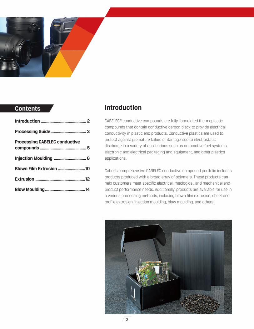
Introduction
CABELEC® conductive compounds are fully-formulated thermoplastic
compounds that contain conductive carbon black to provide electrical
conductivity in plastic end products. Conductive plastics are used to
protect against premature failure or damage due to electrostatic
discharge in a variety of applications such as automotive fuel systems,
electronic and electrical packaging and equipment, and other plastics
applications.
Cabot's comprehensive CABELEC conductive compound portfolio includes
products produced with a broad array of polymers. These products can
help customers meet specific electrical, rheological, and mechanical end-
product performance needs. Additionally, products are available for use in
a various processing methods, including blown film extrusion, sheet and
profile extrusion, injection moulding, blow moulding, and others.

3
Conductive Carbon Black
CABELEC compounds are carefully formulated
products based on conductive carbon black.
The type of carbon black, the addition level and
the dispersion quality are key factors for
achieving good conductivity – or low electrical
resistivity.
Carbon black is a particulate form of industrial
carbon produced by thermal cracking or
thermal decomposition of a hydro-carbon raw
material. Cabot produces carbon black via an
oil furnace process in which petroleum
distillates with high aromatic fractions are
atomized into a preheated, closed furnace
followed by cooling and collection of the
formed carbon black particles.
Electron microscopy inspection reveals that
carbon black is composed of aggregates which
are fused clusters of spherical primary
particles.
CABELEC® CONDUCTIVE COMPOUNDS PROCESSING GUIDE
Figure 1: Carbon black oil furnace process
Oil
Air
Gas
Quench Water
Refractory lined steel shell
Figure 2: Carbon black oil furnace process
INCOMPLETE COMBUSTION
RING FORMATION NUCLEATION PARTICLE FORMATION AGGREGATES
INCOMPLETE COMBUSTION
RING FORMATION NUCLEATION PARTICLE FORMATION AGGREGATES
INCOMPLETE COMBUSTION
RING FORMATION NUCLEATION PARTICLE FORMATION AGGREGATES
Processing Guide
4
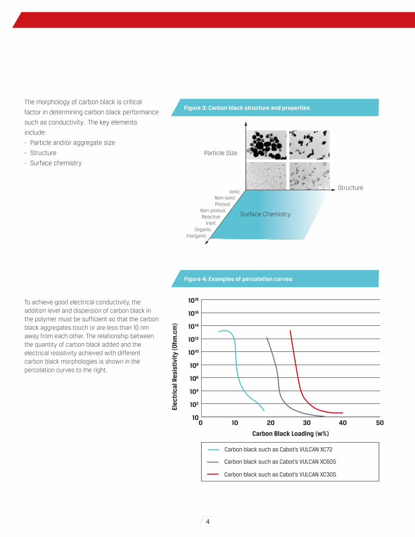
The morphology of carbon black is critical
factor in determining carbon black performance
such as conductivity. The key elements
include:
- Particle and/or aggregate size
- Structure
- Surface chemistry
To achieve good electrical conductivity, the addition level and dispersion of carbon black in the polymer must be sufficient so that the carbon black aggregates touch or are less than 10 nm away from each other. The relationship between the quantity of carbon black added and the electrical resistivity achieved with different carbon black morphologies is shown in the percolation curves to the right.
Figure 3: Carbon black structure and properties
Figure 4: Examples of percolation curves
IonicNon-ionicPorous
Non-porousReactive
InertOrganic
Inorganic
Surface Chemistry
Structure
Particle Size
Elec
tric
al R
esis
tivi
ty (O
hm.c
m)
Carbon Black Loading (w%)
Carbon black such as Cabot’s VULCAN XC72
Carbon black such as Cabot’s VULCAN XC305
Carbon black such as Cabot’s VULCAN XC605
10
102
104
106
108
1010
1012
1014
1016
1018
0 10 20 30 40 50

Elec
tric
al R
esis
tivi
ty (O
hm.c
m)
Low Shear High Shear
1012
1010
108
106
104
102
5
Predrying
As the carbon black contained in the CABELEC compounds is
hygroscopic, they should be stored in a dry place. Unless specified in the
Product Data Sheet for the specific grade, CABELEC compounds need to
be predried before processing. Processing an undried CABELEC
compound with a high moisture content can result in deficiencies in the
final product, such as surface blemishes in molded parts, holes in blown
film, and other undesirable results.
Processing
CABELEC compounds can usually be processed on conventional
processing equipment. To promote good electrical and mechanical
properties of the material, it is advisable to process the compounds
under low shear conditions. In fact, conductive carbon black filled
compounds are highly shear sensitive. Too much shear can deteriorate
carbon black networks and reduce conductivity.
Processing equipment and parameters should be carefully selected so
that the shear generated is kept to a minimum. For more details about
specific processing techniques please refer to the processing guidelines
described below for specific CABELEC compounds.
Dilution
CABELEC conductive compounds are designed to provide the highest level
of performance when used alone (i.e., without dilution with non-
conductive materials). Progressive dilution of regrind results in
correspondingly lower fractions of conductive material in the finished part.
Appropriate blending and feeding procedures are required to maintain
desired resistivity levels; therefore, it is advisable to measure and monitor
the electrical resistivity during processing.
Purging
Due to the high carbon black content of CABELEC compounds, purging of
production equipment is required to prevent discoloration of natural or
light coloured materials that will be processed in the same equipment.
After extrusion of CABELEC products, it is suggested to purge with a
natural, high viscosity resin and to clean the screw and barrel
mechanically.
Processing CABELEC Compounds
Figure 5: Influence of shear on carbon black networks and electrical resistivity
CABELEC® CONDUCTIVE COMPOUNDS PROCESSING GUIDE
66
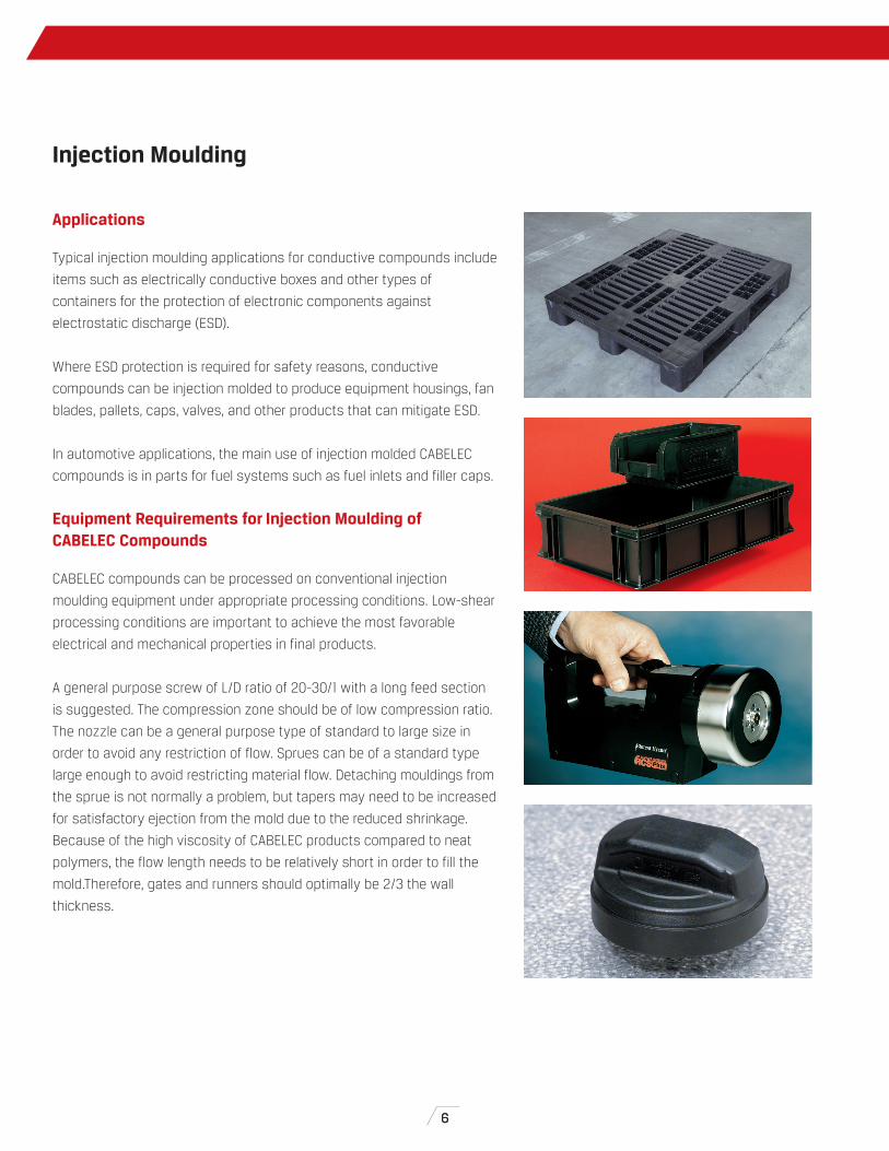
Applications
Typical injection moulding applications for conductive compounds include
items such as electrically conductive boxes and other types of
containers for the protection of electronic components against
electrostatic discharge (ESD).
Where ESD protection is required for safety reasons, conductive
compounds can be injection molded to produce equipment housings, fan
blades, pallets, caps, valves, and other products that can mitigate ESD.
In automotive applications, the main use of injection molded CABELEC
compounds is in parts for fuel systems such as fuel inlets and filler caps.
Equipment Requirements for Injection Moulding of CABELEC Compounds
CABELEC compounds can be processed on conventional injection
moulding equipment under appropriate processing conditions. Low-shear
processing conditions are important to achieve the most favorable
electrical and mechanical properties in final products.
A general purpose screw of L/D ratio of 20-30/1 with a long feed section
is suggested. The compression zone should be of low compression ratio.
The nozzle can be a general purpose type of standard to large size in
order to avoid any restriction of flow. Sprues can be of a standard type
large enough to avoid restricting material flow. Detaching mouldings from
the sprue is not normally a problem, but tapers may need to be increased
for satisfactory ejection from the mold due to the reduced shrinkage.
Because of the high viscosity of CABELEC products compared to neat
polymers, the flow length needs to be relatively short in order to fill the
mold.Therefore, gates and runners should optimally be 2/3 the wall
thickness.
Injection Moulding

77
The flow path of the molten material in the mold influences the electrical
resistivity of the molded part. Electrical resistivity will be at its highest at
the injection point and will decrease progressively when moving away
from this point, as demonstrated in the diagram to the right.
Due to the generally higher stiffness of CABELEC products, reduced
forces are required for the ejector pins.
Hot runners can be used but require good tool design, extremely
accurate temperature control and consistent machine settings. It is also
very important that the drying guidelines are strictly followed to avoid
plugging of the hot runners. Material stagnation points should be avoided
by rounding the end of flow channels. Trials with prototype tooling is
suggested before operation with hot runners.
The shrinkage of CABELEC conductive compounds will be significantly
less than that of natural polymers due to the presence of carbon black in
the compounds. Shrinkage values are available on the product data
sheets for most CABELEC compounds typically used in injection
moulding.
Injection point
108
104
100
Elec
tric
al R
esis
tivi
ty (O
hm.c
m)
CABELEC® CONDUCTIVE COMPOUNDS PROCESSING GUIDE
Figure 6: Electrical resistivity levels during molding process

8
0 10 20 30 40 50 60
Prod
uct
Average mold units/10 shots
Conductive PA6
Conductive POM
Static Dissipative PC
Conductive PS
High flowconductive HDPE
ConductiveHDPE
0 10 20 30 40 50 60 70 80
Prod
uct
Average mold (fill factor) units/10 shots
Neat PP
Static dissipative PP
Conductive PP
High impactconductive PP
CABELEC® COMPOUNDS PROCESSING GUIDE
8
General Guidance for Injection Moulding of CABELEC Compounds
As shown on the tables to the right, CABELEC compounds should be
processed at a higher temperature than the corresponding neat polymer.
However, processing cycle times will probably be similar to those for neat
polymer because CABELEC compounds exhibit faster cooling.
Based on the Spiral Flow Test results, the diagrams below compare a) the
flow behaviour of three CABELEC products based on polypropylene (PP)
with that of a neat PP at their typical melt temperature, and b) the flow
behavior of other CABELEC injection moulding products based on different
polymers. The higher the average mold unit, the better the flow.
Figure 7 a) Comparison of flow of PP-based CABELEC products vs. neat PP
b) Comparison of flow of non-PP-based CABELEC products
Processing parameter
Settings versus natural polymer
Barrel temperatures 10-20°C higher
Melt temperatures 10-20°C higher
Injection pressure Lower
Back pressure Lower
Injection speed Lower
Cycle time Should be optimised when other conditions have been set and required conductivity achieved
Polymer base Recommended mold temperature (°C)
Polyacetal 60
Polycarbonate 80-100
Polyethylene 40-50
Polypropylene 30-40
Polystyrene 30
CABELEC® COMPOUNDS PROCESSING GUIDE
Table 1: CABELEC compounds processing suggestions
Table 2: Mold temperature recommendations for CABELEC compounds

99
Troubleshooting Guide for Injection Moulding
Problem Potential Cause Potential Corrective Actions
Lack of conductivity Shear too highToo much regrindDilution too great
Increase temperature, reduce injection speed and back pressureReduce or remove regrindReduce or remove natural resin
Inhomogeneous surface resistivity
Non-homogeneity related to mold design Review mold design
Cavity not filled Viscosity too highSprues, runners or gates too narrowShot weight too lowMelt temperature too lowMold temperature too lowInjection time too short
Gradually increase melt temperature 5-10°C at a timeIncrease size of sprue, runners, gatesIncrease shot weightIncrease melt temperatureIncrease mold temperatureIncrease injection time
Part sticking in mold Low shrinkage Reduce injection speed and injection andholding pressure
Weld lines Flow path too short Increase barrel temperature and mold temperature
Poor surface finish MoistureGas entrapmentContamination on mold surface
Dry CABELEC compound according to guidelines in product data sheetVent moldClean mold surface
Silver streaking Mold temperature too lowScrew speed too highMoistureMelt temperature too low
Increase mold temperatureDecrease screw speedDry CABELEC compound according to guidelines in product data sheetIncrease melt temperature
Brittleness of part Back pressure too lowScrew speed too highMoisturePresence of contamination
Increase back pressureReduce screw speedDry CABELEC compound according to guidelines in product data sheetCheck for contamination
Blisters MoistureScrew speed too high
Dry CABELEC compound according to guidelines in product data sheetReduce screw speed
Excessive flash Injection pressure too highClamp pressure too lowDirt on mold facesMold not shutting correctly
Reduce injection pressureIncrease clamp pressureClean mold facesCheck mold faces for proper fit
Gas Burns Insufficient venting of moldInjection speed too highScrew speed too highBack pressure too highClamp pressure too high
Ensure vents are clear of obstructions, add further vents if necessaryReduce injection speedReduce screw speedReduce back pressureReduce clamp pressure, increase melt temperature ifnecessary
Oversized part Mold temperature too lowCycle time too longInjection speed too highInjection and holding pressure too high
Increase mold temperatureReduce overall cycle timeReduce injection speedReduce injection and holding pressure
Undersized part Holding time too lowMelt temperature too lowGate too narrowMold temperature too high
Increase holding timeIncrease melt temperatureIncrease size of gateDecrease mold temperature
Sink marks Holding time and pressure too lowMold temperature too highGate too narrowGate incorrectly positioned
Increase holding time and pressureReduce mold temperatureIncrease size of gateLocate gates near heavy cross sections
Warping Molded in stress
Uneven mold temperatureEjected part not cooled enoughEjectors not designed correctly
Raise melt temperature, reduce injection speed, relocate gate if necessaryCheck mold temperatureIncrease cooling time, reduce mold temperatureRedesign ejectors
Voids MoistureMold temperature too low
Dry CABELEC compound according to guidelines in product data sheetIncrease mold temperature
CABELEC® CONDUCTIVE COMPOUNDS PROCESSING GUIDE

10
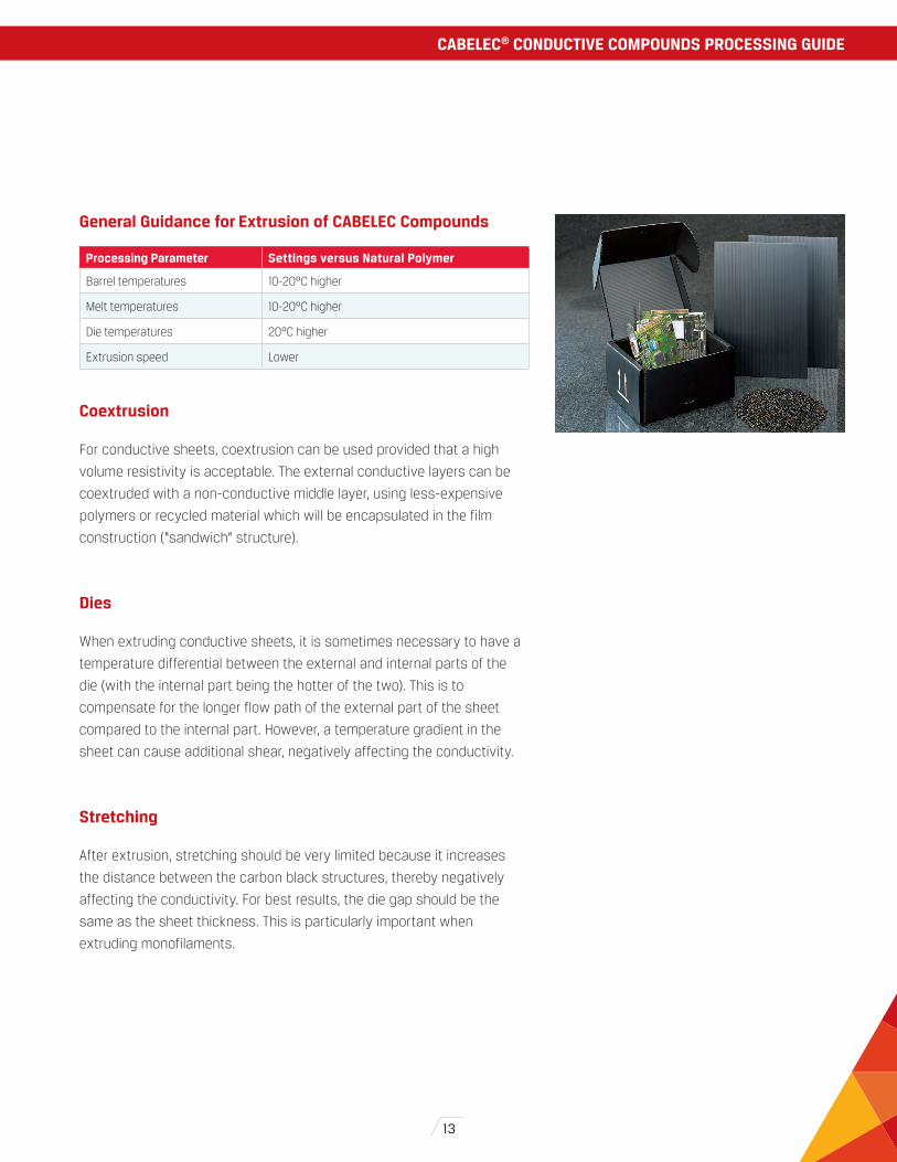
Applications
• Film for packaging of electronic components
• Film for photographic applications
• Liners for big bags for explosive powders
• Packaging materials for explosive powders or other substances used
in an explosive environment (as required by the ATEX norms)
Equipment Requirements for Blown Film Extrusion of CABELEC Compounds
CABELEC compounds can be processed on conventional blown film
extruders under appropriate conditions. To promote good electrical and
mechanical properties of films, CABELEC compounds should be
processed under low shear conditions.
A general purpose screw of L/D ratio of 20-30/1 with a long feed section
is suggested. The compression zone should have a low compression
ratio. The die head geometry should be designed to avoid or minimise
any restriction of flow.
General Guidance for Blown Film Extrusion of CABELEC Compounds
Cooling of conductive films is normally more rapid than that of
transparent, non-conductive films because their high carbon black
content increases thermal conductivity. This factor should be taken into
account when setting the process conditions.
The surface resistivity of a film is related to the film thickness: resistivity
increases as the film thickness decreases. It is also important to avoid a
large blow up ratio as this will increase separation of the carbon black
structures thereby reducing the conductivity of the film.
Blown Film Extrusion
Processing parameter
Settings versus natural polymer
Barrel temperatures 10-20°C higher
Melt temperatures 10-20°C higher
Die temperatures 20°C higher
Extrusion speed Lower
Table 3: Temperature setting suggestions for CABELEC Compounds

11
Coextrusion
For conductive films, coextrusion can be used provided that a high
volume resistivity is acceptable. The external conductive layers can be
coextruded with a non-conductive middle layer, using less-expensive
polymers or recycled material which will be encapsulated in the film
construction (“sandwich” structure).
Printing
Corona treatment should not be used on a conductive film. However,
printing processes which do not require Corona treatment, for example
laser printing, can be used.
Sealing
Conductive films can be sealed using standard sealing equipment. Because
of the high thermal conductivity of CABELEC compounds with respect to
unfilled polymers, it may be necessary to increase the sealing temperature.
Troubleshooting Guide for Blown Film Extrusion
Problem Potential cause Potential Corrective Actions
Lack of conductivity Shear too highToo much regrindDilution too greatStretching too highFilm too thin
Increase temperature, reduce speedReduce or remove regrindReduce or remove natural resinReduce blow up ratioIncrease film thickness
Bad sealing strength Thermal conductivity Increase sealing temperature and pressure
Curling of film Inhomogeneous coolingDifference in shrinkage between the layers of a coextruded film
Reduce line speedAdapt wall thickness
Sticking of the film during winding
Film too hot during winding Reduce speed and/or increase air cooling
Die deposit Moisture Dry CABELEC compound according to guidelines in product data sheet
Voids and holes Moisture Dry CABELEC compound according to guidelines in product data sheet
CABELEC® CONDUCTIVE COMPOUNDS PROCESSING GUIDE

12
Applications
Conductive compounds are widely used in the electronics industry.
Examples of applications are:
• Polystyrene carrier tapes
• Polystyrene thermoformed trays
• Polypropylene corrugated sheet
• Polyethylene/EVA foam
Conductive compounds are also used in industrial applications such as:
• Tubes, pipes, corrugated tubes for hazardous areas (mines, powder or
chemical factories)
• Polyolefin monofilament fibres for antistatic big bags for handling of
dangerous goods
• Conveyor belts
To facilitate compliance with ATEX norms, CABELEC conductive
compounds can offer a valuable solution to producers who require
conductive materials with a surface resistivity below 106 Ohms/sq.
Equipment Requirements for Extrusion of CABELEC Compounds
CABELEC compounds can be processed on conventional extrusion
equipment under appropriate processing conditions. To promote good
electrical and mechanical properties of the extruded part, CABELEC
compounds should be processed under low shear conditions.
A general purpose screw of L/D ratio of 20-30/1 with a long feed section
is suggested. The compression zone should have a low compression
ratio. The die can be a general purpose type of standard to large size in
order to avoid any restriction of flow.
Extrusion
13
General Guidance for Extrusion of CABELEC Compounds
Coextrusion
For conductive sheets, coextrusion can be used provided that a high
volume resistivity is acceptable. The external conductive layers can be
coextruded with a non-conductive middle layer, using less-expensive
polymers or recycled material which will be encapsulated in the film
construction (“sandwich” structure).
Dies
When extruding conductive sheets, it is sometimes necessary to have a
temperature differential between the external and internal parts of the
die (with the internal part being the hotter of the two). This is to
compensate for the longer flow path of the external part of the sheet
compared to the internal part. However, a temperature gradient in the
sheet can cause additional shear, negatively affecting the conductivity.
Stretching
After extrusion, stretching should be very limited because it increases
the distance between the carbon black structures, thereby negatively
affecting the conductivity. For best results, the die gap should be the
same as the sheet thickness. This is particularly important when
extruding monofilaments.
Processing Parameter Settings versus Natural Polymer
Barrel temperatures 10-20°C higher
Melt temperatures 10-20°C higher
Die temperatures 20°C higher
Extrusion speed Lower
CABELEC® CONDUCTIVE COMPOUNDS PROCESSING GUIDE

14
Problem Potential cause Potential Corrective Actions
Lack of conductivity Shear too high Increase temperature, reduce speed
Too much regrind Reduce or remove regrind
Dilution too great Reduce or remove natural resin
Material too stretched Avoid stretching after extrusionAvoid nip beads. Ensure homogeneous cooling by adjusting temperatures of calenders and die
Inhomogeneous surface resistivity
Non-homogeneity related to thermoforming process
Increase thickness, review thermoforming process by avoiding excessive material stretching
Poor surface finish Moisture Dry CABELEC compound as described in product data sheet
Die deposit Moisture Dry CABELEC compound as described in product data sheet
Voids Moisture Dry CABELEC compound as described in product data sheet
Calenders
If the extruded sheet has to pass between two calenders (nips) for
cooling, it is advised that the upper roll be set at a temperature 6-10° C
above the lower roll. The rotating bead between the calendar rolls should
be minimized. High shear generated in this bead can dramatically
degrade the surface resistivity of the material.
Extruders with mixing elements, restrictions in the barrel, high
compression ratios, melt pumps or tight screen packs should be avoided.
Low screw speeds are advisable. It is also important to avoid beads on
calender rolls, to optimise nip roll temperatures and to match extrusion
and haul-off speeds.
Thermoforming
Special care needs to be taken during the thermoforming process due to the
varying degrees of shear to which different parts of the sheet are subjected.
Conductivity can be lost in vertical sections due to separation of the carbon
black structures. The surface resistivity will be highest in the thinnest parts
of the thermoformed article as illustrated in the graph to the right:
Troubleshooting Guide for Extrusion
4 mm 4 mm
1 mm 1 mm
2.5 mm
Elec
tric
al R
esis
tivi
ty (O
hm.c
m)
100
104
108
1012
Figure 8: Influence of the thickness within the thermoformed article on its electrical resistivity
15
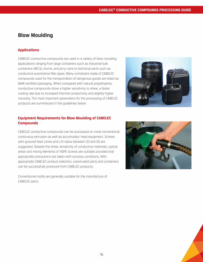
Applications
CABELEC conductive compounds are used in a variety of blow moulding
applications ranging from large containers such as industrial bulk
containers (IBC’s), drums, and jerry-cans to technical parts such as
conductive automotive filler pipes. Many containers made of CABELEC
compounds used for the transportation of dangerous goods are listed as
BAM-certified packaging. When compared with natural polyethylene,
conductive compounds show a higher sensitivity to shear, a faster
cooling rate due to increased thermal conductivity and slightly higher
viscosity. The most important parameters for the processing of CABELEC
products are summarized in the guidelines below.
Equipment Requirements for Blow Moulding of CABELEC Compounds
CABELEC conductive compounds can be processed on most conventional
continuous extrusion as well as accumulator head equipment. Screws
with grooved feed zones and L/D ratios between 20 and 30 are
suggested. Despite the shear sensitivity of conductive materials, typical
shear and mixing elements of HDPE screws are suitable provided that
appropriate precautions are taken with process conditions. With
appropriate CABELEC product selection, coextruded parts and containers
can be successfully produced from CABELEC products.
Conventional molds are generally suitable for the manufacture of
CABELEC parts.
Blow Moulding
CABELEC® CONDUCTIVE COMPOUNDS PROCESSING GUIDE

16
General Guidance for Blow Moulding of CABELEC Compounds
The main process parameters that should be considered are listed below with their corresponding comments/explanations:
Processing Parameters Comments / Suggestions
Temperatures Melt temperatures: typical range: 200-240°CDie lip temperature: typical range: 210-240°CToo low a die lip temperature can affect resisitivity even at higher melt temperatures. It can also generate variation in conductivity along the circumference of the parison
Piston or Ram speed On accu-head lines, the ram speed should be kept as low as possible due to the high shear rates generated during parison formation
Screw speed Conventional screw speed levels for natural polymers can be used
Mold closing speed As for natural HDPE, the appropriate balance needs to be found to achieve good welding quality. An excessive speed (or too late a transition point to reduced speed) can lead to an inappropriate weld geometry
Parison cooling/mold cooling
CABELEC compounds exhibit a far higher thermal conductivity than natural polymers. As a result, parison cooling is faster. This leads to shorter cooling times but also needs to be taken into consideration for the welding line quality
Melt strength Due to the carbon black network, CABELEC products are characterised by high melt strength levels which facilitate a tight thickness distribution profile
Mold temperatures As for natural polyethylene, low mold tempertaures are preferable to minimise cycle time (typical cooling water temperatures: 10-25°C)
Troubleshooting Guide for Blow Moulding
Problem Potential cause Potential Corrective Actions
Rough surface Melt temperature too lowDie temperature too lowRam speed too high
Increase melt and die temperatures
Reduce ram speed
Flow marks/surface defects Purge effect due to high viscosity of CABELEC compounds
Complete purge of the equipment
Bubbles Air entrapment, excessive moisture level Vent the equipment, pre-dry material
Weld seam is too weak Melt temperature is too lowExtrusion/ram speed too lowMold closing speed inappropriate
Adjust melt temperaturesIncrease ram speedAdjust mold closing speed and change-over limits
Uneven appearance on mold surface
Insufficient or non homogeneous venting Improve venting
Surface resistivity too high Die lip temperature too lowMelt temperature too lowExcessive shear
Increase (significantly) die lip and melt temperature
Reduce ram/piston speed
Uneven resistivity levels Uneven parison resistivityUneven stretching/blow up ratios
Increase head/die temperaturesVerify thickness distribution
The CABELEC name is a registered trademark of Cabot Corporation.
The data and conclusions contained herein are based on work believed to be reliable, however, Cabot cannot and does not guarantee that similar results and/or conclusions will be obtained by others. This
information is provided as a convenience and for informational purposes only. No guarantee or warranty as to this information, or any product to which it relates, is given or implied. This information may contain
inaccuracies, errors or omissions and CABOT DISCLAIMS ALL WARRANTIES EXPRESS OR IMPLIED, INCLUDING MERCHANTABILITY OR FITNESS FOR A PARTICULAR PURPOSE AS TO (i) SUCH INFORMATION, (ii) ANY PRODUCT
OR (iii) INTELLECTUAL PROPERTY INFRINGEMENT. In no event is Cabot responsible for, and Cabot does not accept and hereby disclaims liability for, any damages whatsoever in connection with the use of or reliance
on this information or any product to which it relates.
cabotcorp.com© 2014 Cabot Corporation.
09/2014
NORTH AMERICACabot Corporation Business
and Technology Center
157 Concord Road
P.O. Box 7001
Billerica, MA 01821 - USA
Technical service
Tel: +1 800 462 2313
Customer service
Tel: +1 678 297 1300
Fax: +1 678 297 1245
SOUTH AMERICACabot Brasil Industria
e Comericio Ltda.
Rua do Paraiso 148 - 5 andar
04103-000 Sao Paolo,
SP Brazil
Tel: +55 11 2144 6400
Fax: +55 11 3253 0051
EUROPESIA Cabot Latvia
101 Mukusalas Street
Riga, LV-1004,
LATVIA
Tel: +371 6705 0984
Tel: +371 6705 0900
Fax: +371 6705 0985
MIDDLE EAST & AFRICACabot Dubai
P.O. Box 17894
Jebel Ali Free Zone
LOB 15, Office 424
Dubai
United Arab Emirates
Tel: +971-4-8871800
Fax: +971-4-8871801
ASIA PACIFICCabot China Ltd.
558 Shuangbai Road
Shanghai 201108
China
Tel: +86 21 5175 8800
Fax: +86 21 6434 5532
JAPANCabot Specialty Chemicals Inc.
Sumitomo Shiba-Daimon Bldg. 3F
2-5-5 Shiba Daimon,
Minato-ku
Tokyo 105-0012
Japan
Tel: +81 3 6820 0255
Fax: +81 3 5425 4500
Cabot: A Proud History and Global Reach
Cabot Corporation is a global performance materials company, and we strive to be our customers’ partner of choice. We have been a leading manufacturer for more than 130 years. Our global reach enables us to partner closely with our customers to meet the highest standards for performance, quality, and service.