cab # 11930 for · cab # 11930 for x465, x475, x485, x495, x575, x585, x595, x700, x720, x724, ......
TRANSCRIPT

Cab # 11930 For
X465, X475, X485, X495, X575, X585, X595, X700, X720, X724, X728, X729, X740, X744, X748, X749
John Deere Garden Tractors
OPERATION - PARTS LIST - ASSEMBLY
IMPORTANT READ THIS MANUAL CAREFULLY AND KEEP FOR FUTURE REFERENCE
CAUTION REMOVE THE VINYL PANELS FOR TRANSPORT IN AN OPEN TRUCK OR TRAILER
! WARNING THIS CAB WILL NOT PROTECT OPERATOR FROM INJURIES CAUSED BY ROLLOVER, COLLISION, OR OTHER
ACCIDENTS 11930713 1

WARNING
This cab is designed to provide foul weather protection only. It does not provide protection from noise, exhaust fumes, chemicals or injury from collision, or other accidents. 1. Do not operate machine in confined areas without proper ventilation 2. Thoroughly check area of operation before using machine 3. The cab adds height to the machine. Low tree limbs and other overhead structures that did not interfere with the operation of the machine before, may now be obstacles
IMPORTANT!
The doors are a part of the cab structure. The cab doors should always be closed during use to prevent damage to the cab frame.
MAINTENANCE INSTRUCTIONS Periodically check all bolts to see that they are tight. If bolts become loose, failure of cab parts may occur. Door latches and hinges should be lubricated with light machine oil for proper operation.
DO NOT CLEAN THE CLEAR PLASTIC WINDOWS WHEN THE PLASTIC IS DRY. THE CLEAR PLASTIC WILL SCRATCH.
Avoid contact with plastic windows. Keep plastic windows clean by washing them with clear running water and rubbing with your bare hands, only. The use of a rag, sponge or brush will scratch the plastic. Liquid soap may also be used for window cleaning. During freezing weather, an automotive windshield washer solvent may be used. Use liquid soap and water to clean colored vinyl portions. Scrubbing with a brush or rag is also permitted on the colored vinyl portions
STORAGE INSTRUCTIONS Prior to storage clean the windows and colored vinyl parts with a mild automotive detergent, rinse with clean water and allow to thoroughly dry, Store cab in a clean dry place out of direct sunlight. Avoid folding plastic windows.
READ THIS MANUAL COMPLETELY BEFORE BEGINNING INSTALLATION.
• The right side of the machine is determined from the operators seated position. • Right Hand parts are identified with orange label.
• The words "bolt" will refer to a 1/4”x5/8” bolt and "lock nut"’ will refer to a 1/4” locknut
unless specified otherwise.
• Do not tighten bolts during assembly unless instructed to do so. 2

For Replacement Parts and Accessories Contact:
Original Tractor Cab Co., Inc. P.O. Box 97 6849 W. Front St.
Arlington, IN 46104 Phone 765-663-2214 Fax 765-663-2101
Email [email protected]
Visit us on the web to see our other products. www.originalcab.com
Cabs for Lawn Tractors, Garden Tractors, Compact Tractors, Snow Blowers, Utility Vehicles
Sunshades for Tractors, Mowers, & Utility Vehicles
.
LIMITED WARRANTY
COVERED BY WARRANTY ORIGINAL TRACTOR CAB CO., INC., (the "Company") warrants to the owner that each new product listed below is merchantable and free of defects in workmanship and material. During the warranty period, the dealer from whom the product was bought, or the Company, will provide, free of charge, parts and the shipping costs of parts necessary to correct any defect in workmanship and material.
WARRANTY PERIOD The company products listed below are warranted for the stated period from the date of the original purchase: 1. Cabs for tractors and snow removal equipment 1 Year 2. Company manufactured accessories for above cabs 1 Year 3. Sunshades for lawn and garden tractors 1 Year 4. Repair parts 1 Year OWNER'S RESPONSIBILITIES The owner of a new Company manufactured product must do the following to qualify for warranty service:
1. Retain the original invoice or other proof of purchase to avoid unnecessary difficulties in determining eligibility for warranty work. 2. Notify the dealer from whom the product was bought, or the company, as soon as possible after discovery of a possible defect, and provide proof of original purchase. To notify the company write to: Original Tractor Cab Co., Inc., P.O. Box 97, Arlington, IN 46104. 3.The owner may, upon notification by the Company, be required to return the defective part, or parts, to the Company for inspection and warranty service.
NOT COVERED BY WARRANTY The following are not covered by this warranty:
1. Transportation charges to and from servicing dealer or the Company; 2. New products that have been subject to misuse, negligence or accident, or have been altered or repaired in a manner not authorized by the company; 3. Windshield wipers, lights, or accessories that are warranted separately by their respective manufacturers, except Company agrees to make available to the owner whatever warranty benefits may be made available to the Company by the manufacturers. All implied warranties, except to the extent prohibited by any applicable law, shall have no greater duration than the warranty period for the applicable product, some states do not allow limitation on how long an implied warranty lasts, so the above limitation may not apply to you. The Company’s' liability arising out of warranties representation, instructions, or defects from any abuse, shall be limited exclusively to repair or replacing parts under the condition in the warranty, and in no event will Company be liable for incidental or consequential damages. Some states do not allow the exclusion or limitation of incidental or consequential damages, so the above limitation or exclusion may not apply to you.This warranty gives you specific legal rights, and you may also have rights that vary from state to state.
3

Carton Contents: Cab #11930 Key # Part # Qty. Description 1 11158 1 Foot, RH 2 11159 1 Foot, LH 3 11160 1 Front Panel Brace, RH 4 11161 1 Front Panel Brace, LH 5 11164 2 Front Panel Bracket 6 11162 1 Front Panel Leg, RH 7 11163 1 Front Panel Leg, LH 8 11165 1 Front Panel Cross Bar 9 11166 2 Foot Pocket Guard 10 10004 2 Front Post 11 10002 1 Top Frame Brace, RH 12 10003 1 Top Frame Brace, LH 13 11168 1 Rear Bracket Mount, RH 14 11246 1 Rear Bracket Mount, LH 15 11167 1 Rear Bracket, RH 16 11247 1 Rear Bracket, LH 17 11248 1 Rear Bracket Support 18 11169 1 Rear Boxing Post, RH 19 11750 1 Rear Post, RH. 20 11170 1 Rear Boxing Post, LH 21 11249 1 Rear Post, LH 22 10001 1 Top Frame 23 11171-B 1 Door, RH 24 11172 1 Door Bottom, RH 25 11173-B 1 Door, LH 26 11174 1 Door Bottom, LH 27 10749-B 1 Windshield 28 11175-B 1 Front Panel Vinyl 29 11176-B 1 Rear Curtain 30 11197 1 ABS Plastic Top 31 11205 1 Exhaust Deflector 32 11243 1 Control Cable Bracket 9820 1 Door Hardware Package 11937 1 Hardware Package (contents listed below) 9815 3 1/4”-20 x 1/2 Bolt 786 24 1/4"-20 x 5/8" Bolt 788 12 1/4"-20 x 3/4" Bolt 730 39 1/4"-20 Two-Way Lock Nut 3951 4 1/4" Flat Washer 60246 6 1/4" x 1 1/4" x 3/16" Thick Fender Washer 784 1 5/16”-18 X 3/4” Bolt 785 5 5/16"-18 x 1" Bolt 1093 1 5/16"-18 x 1 1/4" Bolt 729 7 5/16"-18 Two-Way Lock Nut 7 4 5/16" Flat Washer 7628 1 # 10-24 x 1/2" Self Tapping Screw 4902 2 Plastic Protectors
4

Identify the steel parts using the Carton Contents and the illustration below.
1
2
3
4
5
5
6
7
8
99
10
11
12
13
14
15
16
17
18
19
20
21
22

STEP 1; SEE FIGURE 1:
FIGURE 1
Prepare tractor. A. Pull the mats loose from the step plates by squeezing the buttons together and pulling up. B. Cut the buttons off that are circled in the photo.
NOTE: The mats are removed for clarity. Removing the motion control pedals and differential lock pedal to remove the mats is not necessary to complete steps 1 & 2.
STEP 2; SEE FIGURE 2: Install Foot RH (1), LH (2),Front Panel Brace
RH (3), LH (4) and the Front Panel Brackets (5).
A. Remove the bolt at Reference A. Place the
right Foot on the step plate. Insert a 5/16” x 1” bolt down through the holes at Reference A. Add a 5/16” locknut. Do not tighten at this time. Insert 1/4” x 3/4” bolts down through the other hole add a 1/4” fender washer and 1/4” lock nut. Do not tighten at this time.
FIGURE 2
B. Place the right Front Panel Brace on the step plate. Insert 1/4” x 3/4” bolt down through the holes add a 1/4” fender washer and 1/4” lock nut. Do not tighten at this time. C. Place a Front Panel Bracket on the step plate. Insert 1/4” x 3/4” bolt down through the holes add a 1/4” fender washer and 1/4” lock nut. Do not tighten at this time. D. Repeat on the left side.
3
5
1
A
6
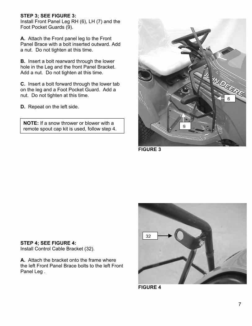
STEP 3; SEE FIGURE 3: Install Front Panel Leg RH (6), LH (7) and the Foot Pocket Guards (9).
FIGURE 3
A. Attach the Front panel leg to the Front Panel Brace with a bolt inserted outward. Add a nut. Do not tighten at this time. B. Insert a bolt rearward through the lower hole in the Leg and the front Panel Bracket. Add a nut. Do not tighten at this time. C. Insert a bolt forward through the lower tab on the leg and a Foot Pocket Guard. Add a nut. Do not tighten at this time.
9
6 D. Repeat on the left side.
NOTE: If a snow thrower or blower with a remote spout cap kit is used, follow step 4.
FIGURE 4
32 STEP 4; SEE FIGURE 4: Install Control Cable Bracket (32). A. Attach the bracket onto the frame where the left Front Panel Brace bolts to the left Front Panel Leg .
7

STEP 5; SEE FIGURE 5: Install Front Panel Cross Bar (8). A. Place the Cross Bar tabs in front of legs. Insert the four bolts to the rear. Add locknuts. Do not tighten at this time.
B. The flattened ends of the Cross Bar should be vertical when installed.
FIGURE 5 STEP 6; SEE FIGURE 6: Install Front Posts (10) and Top Frame Brace
RH (11) & LH (12).
FIGURE 6
A. Insert a 1/4” x 3/4” bolt forward through the end of the Front Panel Cross Bar, the tab on the post and then the lower end of the right Top Frame Brace. Add a nut and tighten just enough to hold the brace up.
NOTE: Bent ends of Top Frame Braces will point rearwards and lay flat when properly installed.
B. Insert a 1/4” x 3/4” bolt outward through the lower hole in the Foot, the lower hole in the post and then the hole in the Foot Pocket Guard. Add a nut. Do not tighten at this time. C. Insert a bolt out through the upper hole in the Foot And Post. Place a door hinge from the Door Hardware Package over the bolt and add a nut. Do not tighten at this time. D. Repeat the above steps on the left side.
8
10
11
NOTE: If you are installing the safety glass windshield omit Top Frame Braces.
8
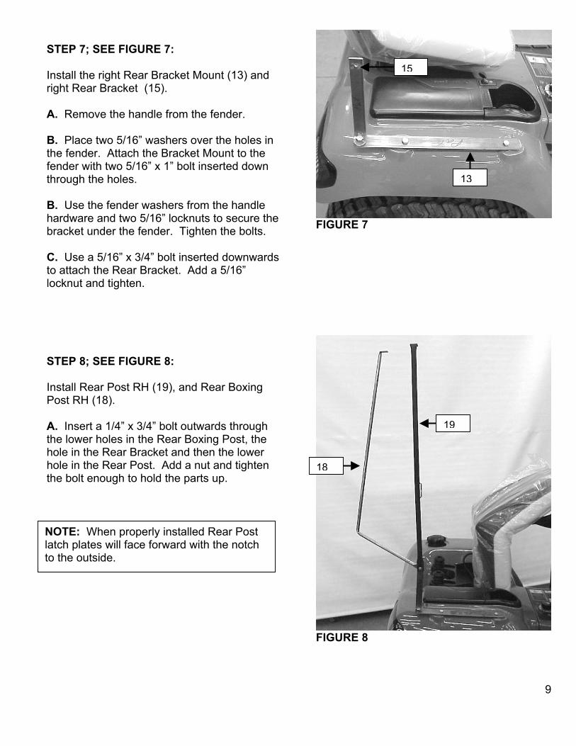
FIGURE 7
STEP 7; SEE FIGURE 7:
13
15Install the right Rear Bracket Mount (13) and right Rear Bracket (15). A. Remove the handle from the fender. B. Place two 5/16” washers over the holes in the fender. Attach the Bracket Mount to the fender with two 5/16” x 1” bolt inserted down through the holes. B. Use the fender washers from the handle hardware and two 5/16” locknuts to secure the bracket under the fender. Tighten the bolts. C. Use a 5/16” x 3/4” bolt inserted downwards to attach the Rear Bracket. Add a 5/16” locknut and tighten.
FIGURE 8
STEP 8; SEE FIGURE 8: Install Rear Post RH (19), and Rear Boxing Post RH (18).
19A. Insert a 1/4” x 3/4” bolt outwards through the lower holes in the Rear Boxing Post, the hole in the Rear Bracket and then the lower hole in the Rear Post. Add a nut and tighten the bolt enough to hold the parts up.
18
NOTE: When properly installed Rear Post latch plates will face forward with the notch to the outside.
9

FIGURE 9
STEP 9; SEE FIGURE 9: Prepare tractor. A. Remove the left handle and the gas tank support. STEP 10; SEE FIGURE 10: Install the left Rear Bracket Mount (14). A. Place two 5/16” washers over the holes in the fender. Place the left Bracket Mount on the left fender over the gas filler as shown. B. Insert a 5/16” x 1” bolt down through the forward hole. Add a 5/16” fender washer from the handle hardware and a 5/16” nut. Do not tighten at this time.
FIGURE
C. Insert a 5/16” x 1 1/4”” bolt down through the rearward holes. Add a 5/16” fender washer from the handle hardware. Place the gas tank support over the bolt. Add 5/16” nut. Tighten the bolts. STEP 11; SEE FIGURE 11: Install left Rear Bracket (16), Rear Bracket Support (17) left Rear Post (21) and left Rear Boxing Post (20).
FIGURE
A. Place the left rear Bracket against the outside of the left rear bracket mount. Insert a 1/4” x 1/2” bolt through the holes Add a nut. Do not tighten at this time. B. Place the Rear Bracket Support against the outside of the left rear bracket mount. Insert a 1/4” x 1/2” bolt through the holes. Add a nut. Do not tighten at this time. C. Attach the Boxing Post to the Rear Bracket mount with a 1/4” x 1/2” bolt and locknut. Add a nut and tighten enough to hold the post upright. D. Attach the Post to the Rear Bracket and rear Bracket Support with a 1/4” x 3/4” bolt and nut. Tighten enough to hold the post upright.
14
10
11
21
20
17
16
10

STEP 12; SEE FIGURE 12:
FIGURE 12
Install the Top Frame (22). A. Use eight bolts inserted upward to attach the Top Frame to the bent ends of the Posts and Top Frame Braces. Add nuts. Do not tighten at this time.
NOTE: The front of the Top Frame has the “L” tabs located closest to the corners.
B. Place a Plastic Protector over the bent ends of each rear post. (See inset)
STEP 13; SEE FIGURE 13: Install the Doors for frame / door alignment. A. Follow the instructions in the Door Hardware Package to install the Door Bottoms and the Door Latches. B. Install Doors, do not tighten top hinge bolts, as doors will be removed after alignment. C. Close and latch both Doors. D. Tighten all framework bolts at this time. E. Remove the doors at top hinge.
FIGURE 13
22
11
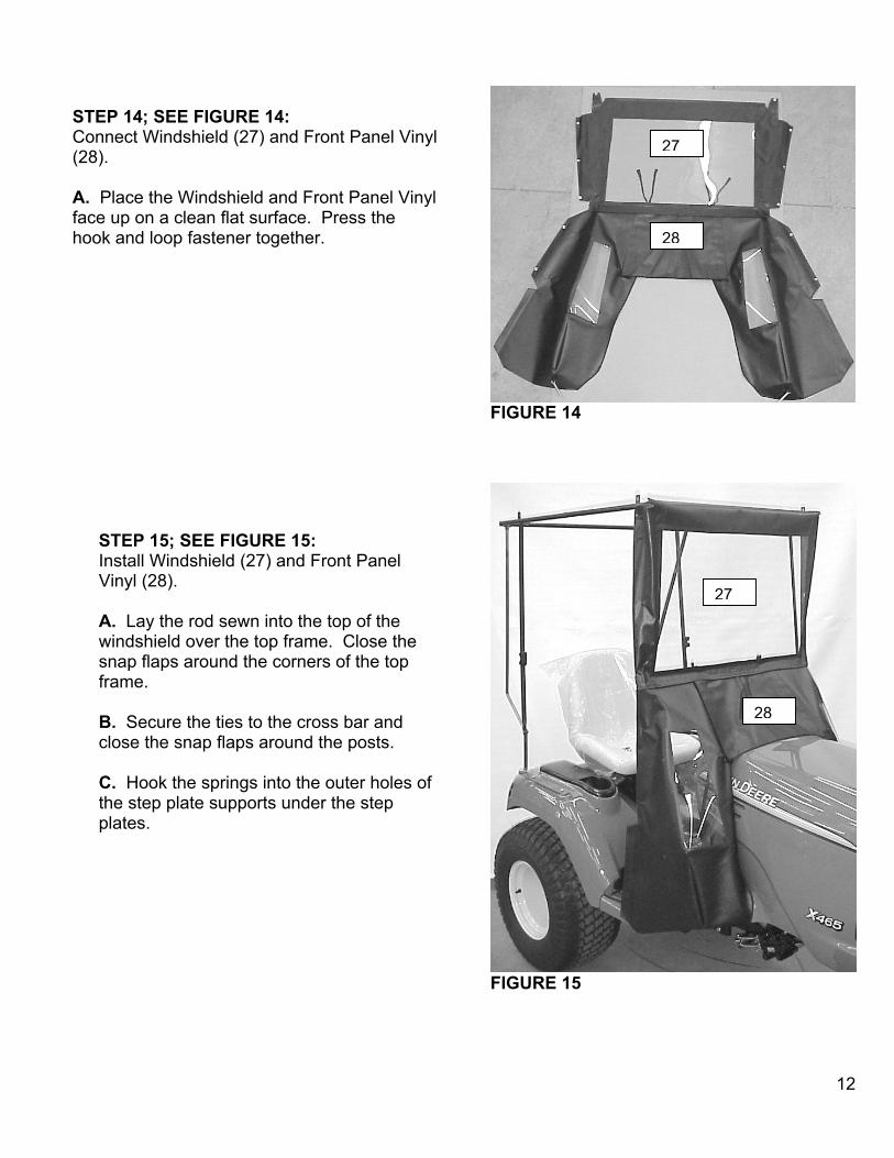
FIGURE 14
STEP 14; SEE FIGURE 14: Connect Windshield (27) and Front Panel Vinyl (28). 27
A. Place the Windshield and Front Panel Vinyl face up on a clean flat surface. Press the hook and loop fastener together. 28
FIGURE 15
STEP 15; SEE FIGURE 15: Install Windshield (27) and Front Panel Vinyl (28). A. Lay the rod sewn into the top of the windshield over the top frame. Close the snap flaps around the corners of the top frame. B. Secure the ties to the cross bar and close the snap flaps around the posts. C. Hook the springs into the outer holes of the step plate supports under the step plates.
27
28
12

FIGURE 16
NOTE: If a snow thrower or blower with remote spout cap kit is used install the cable assembly into the cab by following step16.
STEP 16; SEE FIGURE 16: Install spout cap control cable assembly. A. Remove the screw and handle from the cable assembly. Remove the 1st nut from the stem. B. Insert the stem through the slot in the front panel vinyl and then the bracket. C. Replace the hardware and tighten.
29STEP 17; SEE FIGURE 17: Install Rear Curtain (29). A. Lay the rod sewn into the rear curtain over the rear of the top frame. Close the snap flaps at the corners. B. Close the snap flaps over the rear posts and brackets. C. Snap the flaps around the left Rear Bracket. Secure the inner pocket to the Rear Bracket Support with the ties.
FIGURE 17 13
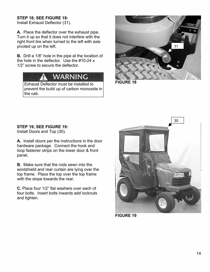
STEP 18; SEE FIGURE 18:
Install Exhaust Deflector (31). A. Place the deflector over the exhaust pipe. Turn it up so that it does not interfere with the right front tire when turned to the left with axle pivoted up on the left. 31 B. Drill a 1/8” hole in the pipe at the location of the hole in the deflector. Use the #10-24 x 1/2” screw to secure the deflector.
Exhaust Deflector must be installed to prevent the build up of carbon monoxide in the cab.
FIGURE 18
STEP 19; SEE FIGURE 19: Install Doors and Top (30). A. Install doors per the instructions in the door hardware package. Connect the hook and loop fastener strips on the lower door & front panel. B. Make sure that the rods sewn into the windshield and rear curtain are lying over the top frame. Place the top over the top frame with the slope towards the rear. C. Place four 1/2” flat washers over each of four bolts. Insert bolts inwards add locknuts and tighten.
FIGURE 19
30
14