c3.2.2 stream and river crossings c3.2.2.1 hydrology · pdf file2. local scour – the...
TRANSCRIPT

IOWA DOT ~ OFFICE OF BRIDGES AND STRUCTURES ~ LRFD BRIDGE DESIGN MANUAL COMMENTARY ~ C3.2.2: 1
January 2017
C3.2.2 Stream and river crossings
C3.2.2.1 Hydrology

IOWA DOT ~ OFFICE OF BRIDGES AND STRUCTURES ~ LRFD BRIDGE DESIGN MANUAL COMMENTARY ~ C3.2.2: 2
January 2017

IOWA DOT ~ OFFICE OF BRIDGES AND STRUCTURES ~ LRFD BRIDGE DESIGN MANUAL COMMENTARY ~ C3.2.2: 3
January 2017
C3.2.2.2 Hydraulics
C3.2.2.3 Backwater
C3.2.2.4 Freeboard
C3.2.2.5 Road grade overflow
C3.2.2.6 Streambank protection Riprap placement on streambank 22 December 2006
The following figure is taken from page 35 of the Iowa DNR’s manual How to Control Streambank Erosion (updated 2006). The complete manual, including several pages that discuss riprap, may be downloaded from the following web site:
http://www.iowadnr.gov/water/stormwater/forms/streambank_man.pdf
C3.2.2.7 Scour
Introduction The most common cause of bridge failures in the nation is flooding, with bridge scour being the most common type of flood damage. Bridge scour is a complicated process and provides challenges to engineering analysis. Because of public safety and high replacement and repair costs, the need exists to evaluate or improve current design and maintenance practices concerning bridge foundations.

IOWA DOT ~ OFFICE OF BRIDGES AND STRUCTURES ~ LRFD BRIDGE DESIGN MANUAL COMMENTARY ~ C3.2.2: 4
January 2017
The objective in this document is to detail three items:
1. Factors that affect scour. 2. Recommendations to reduce or prevent scour effects on existing and proposed bridges. 3. Methods to estimate scour for existing and proposed structures.
Definition A basic definition of scour is the result of erosive action of moving water as it excavates and carries away material from a streambed and banks. There are two types of scour:
1. General scour - the loss of material from most or all the bed and banks, usually caused by the road embankment encroaching onto the flood plain with resulting contraction of the flood flow (often called contraction scour).
2. Local scour – the loss of material around piers, abutments, spur dikes and embankments. There are two conditions for contraction and local scour: clear-water and live-bed. Clear-water scour occurs when there is little to no movement of the bed material of the stream upstream of the crossing. Typical situations include most overflow bridges, coarse bed material streams, and flat gradient streams during low flow. Live-bed scour occurs when velocities are high enough to move the bed material upstream of the crossing. Most Iowa streams and rivers experience live-bed scour. Streambed degradation, such as in the Western Iowa loess region, is considered in some documents to be scour. Even though degradation can affect structural stability like local or general scour does, the causes of degradation are of a different nature, and it will not be discussed in detail in this document. The effects of scour are a complex problem involving geotechnical, hydraulic, and structural concerns, so decisions concerning scour should involve engineers in each of these disciplines.
Design guidelines and considerations Numerous factors affect the stability of the bed and banks of a stream and are discussed below with some guidelines and considerations. 1. Soils Soils with any combination of sand or silt have greater potential for scour: sand, silt, sandy silt, sandy silty clay, etc. As a general rule, according to IDOT's Soils Design Section, soils which have a blow count of ten or less are particularly susceptible. Excessive loss of pile bearing due to scour is one cause for bridge damage or failure. However, perhaps a more common cause of failure is soil instability associated with the road embankment and bridge berm. Often a bridge berm or fill behind a high abutment has minimal factor of safety for stability. If this safety factor is reduced due to scour at the toe of the embankment, the soil may become unstable resulting in a slip failure. Damage to an abutment, pier or approach fill is a possible outcome. For replacement structures, designing flatter berm slopes and/or placing the abutments farther from the channel will provide a greater safety factor. Then, when scour does occur, the embankment will more likely remain stable. For existing structures, protection of the berm, especially the toe, may be necessary.

IOWA DOT ~ OFFICE OF BRIDGES AND STRUCTURES ~ LRFD BRIDGE DESIGN MANUAL COMMENTARY ~ C3.2.2: 5
January 2017
2. Substructure Generally, wider and longer piers have greater scour potential. Deeper footings and longer piles are more stable at greater scour depths. Spread footings should be used only on material highly resistant to scour such as limestone and some shales. To maintain the integrity of the structure, do not allow scour to reduce pile bearing below a desirable safety factor that is selected by the structural or geotechnical engineer. Designing for this minimum safety factor may require designing longer piles for new bridges. For existing structures, protection of the piles may be necessary to maintain the safety factor. New bridges should have sufficient length so that the abutments do not encroach on the channel but placed as far back from the streambank as practical. Vertical wall abutments (high abutments) have a greater potential for general and local scour as compared to the spillthrough type (integral or stub abutments). 3. Flood discharge In the publication “Evaluating Scour at Bridges, Fifth Edition”, Hydraulic Engineering Circular No. 18 (HEC-18), the FHWA recommends using scour flood frequencies that are larger than the hydraulic design flood frequencies. The rationale for this is that hydraulic design involves backwater and ensures that the bridge size will be adequate under normal flood conditions. In scour design, a higher discharge is used to ensure that the bridge will remain stable and will not fail or suffer severe damage during extreme flood events. Also, there is a reasonably high likelihood that the hydraulic design flood will be exceeded during the service life of the bridge. Iowa DOT recommends using the Q200or lesser discharge for scour analysis, depending on which results in the most severe scour conditions. Usually the overtopping flood results in the worst scour, so check this flood (if less than the Q200) and the Q200. FHWA also recommends checking scour conditions for a superflood, such as a Q500. If Q500 data is not available, HEC-18 recommends using 1.7 X Q100. The safety factors for the bridge should remain above 1.0 under this flood condition. Similar to that mentioned above, Qovertopping may be the worst-case flood and should be used if it is less than Q500.
4. Interaction between road and flood plain A highly skewed river crossing provides a less hydraulically efficient bridge opening and therefore has a greater contraction scour potential. Also, a high ratio of overbank flow to main channel flow will result in a greater contraction scour potential. For these situations, scour can be reduced by using wing dikes and/or riprap. Road grade overflow or overflow structures may provide relief and reduce scour potential for the main channel bridge. 5. Interaction between piers and flood flow The width, length and type of pier (e.g., pile bents, “tee” piers) all have an effect on local scour. Closely spaced piles in a pile bent pier can act similar to a solid wall. The angle of attack of flood flow to the pier can also significantly increase scour if this angle changes due to channel meandering during the life of the bridge. For example, if the angle of attack changes from 0 to 15, the pier scour approximately doubles. The stream’s history of and future potential for meandering should be examined.

IOWA DOT ~ OFFICE OF BRIDGES AND STRUCTURES ~ LRFD BRIDGE DESIGN MANUAL COMMENTARY ~ C3.2.2: 6
January 2017
6. Debris and ice Visual observation can be made and maintenance records can be checked to determine the history of debris and ice on the stream. Debris and ice can snag on the piers or superstructure, placing additional stresses on the bridge as well as promoting local scour. This scour can sometimes be quite significant although difficult to estimate. Therefore, for new designs, give consideration to raising the low superstructure above the low roadgrade elevation. This will allow hydraulic relief if the bridge opening becomes clogged. Estimating scour Procedures for estimating scour have been researched in the past 40 years in an attempt to develop reliable prediction equations. Some of these equations give reliable results, others do not. The Federal Highway Administration has attempted to find the best equations and published them in HEC-18.
HEC-18 contains equations for contraction scour, abutment scour and pier scour. The contraction scour equations are the best available equations of their type and sometimes provide reliable estimates, although these estimates still need to be evaluated considering soil types, site scour history, etc. The abutment scour equations frequently give questionable estimates. Because of comments similar to this from various states, FHWA is conducting additional research to develop new methods. At this time, IDOT recommends not using FHWA's abutment scour equations or, at most, use them with caution. However, be aware that abutment scour can occur. Concerning pier scour, the equation in HEC-18 generally gives reliable results. However, a much simpler method that gives very similar results is found in Iowa Highway Research Board's Bulletin No. 4, “Scour Around Bridge Piers and Abutments,” by Emmett M. Laursen and Arthur Toch, May 1956. This method for estimating pier scour can be used in most cases instead of the methods in HEC-18. 1. Contraction scour estimation See Chapter 4 of HEC-18 for detailed instructions on how to calculate contraction scour. To help explain this chapter, there are two determinations that must be made when estimating contraction scour:
The appropriate case of contraction scour that depends on the flow interaction of the bridge to the channel and floodplain. There are four of these cases. See the figures later in this document for graphical illustrations of these cases.
The appropriate sediment transport condition. There are two of these conditions and equations (live-bed and clear-water) that can occur in any of the four cases mentioned above.
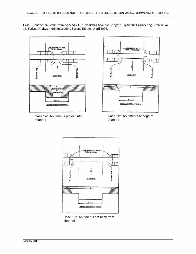
Both determinations are explained below. Four cases of contraction scour Case 1 is overbank flow being forced back into the main channel due to the road fill. The majority of bridges in Iowa will be Case 1. There are three variations to Case 1, depending on the location of the abutments or abutment berms compared to the channel:
Case 1a is normally used when the river channel width becomes narrower due to the bridge abutments (or berms) projecting into the channel. Case 1b does not involve any contraction of the channel itself, but the overbank flow area is completely obstructed by the embankment. In other words, the abutments or abutment berms are on the channel bank.
Case 1c is when the abutments or abutment berms are set back from the channel. This case is more complex because there is both main channel flow and overbank flow in the bridge opening. Therefore, refer to discussion in Section 4.3.4 of HEC-18. More hydraulic analysis may be needed than in Cases 1a and 1b (such as WSPRO) to determine the distribution of flow in the bridge opening, i.e., what is the discharge in the main channel (Q2) and the discharge in the overbank under the bridge (Qoverbank2).

IOWA DOT ~ OFFICE OF BRIDGES AND STRUCTURES ~ LRFD BRIDGE DESIGN MANUAL COMMENTARY ~ C3.2.2: 7
January 2017
)(D y 10.95 = V 500.33 0.167
c
W
W Q
Q =
y
y
2
1
1k
1
2
0.86
1
2
Most Case 1 streams in Iowa will have live-bed scour. However, if the streambed material has particles larger than a sand classification, calculate Vc (see below) to determine if clear-water scour will occur instead of live-bed scour. Case 2 is when the stream has no overbank flow. This case will be common in Western Iowa streams that are severely degraded. Case 3 is an overflow (relief) bridge with no bed material transport, so use the clear-water scour equations. Hydraulic analysis (e.g., using WSPRO) is needed to determine the flood plain width associated with the relief opening and to determine the total flow going through the relief bridge. Case 4 is an overflow (relief) bridge similar to Case 3 except it does have sediment transport (live-bed scour), such as over a secondary channel on the flood plain of a larger stream. Hydraulically this case is no different than Case 1 except that analysis (e.g., using WSPRO) is needed to determine the flood plain width associated with the relief opening and the portion of the total flow going through the relief bridge. Sediment transport conditions: Live-bed scour versus clear-water scour Before an equation is selected to estimate contraction scour, it is necessary to determine if the flow is transporting bed material. If it is, the flow will create live-bed scour. If it is not, the flow will create clear-water scour. There are different scour equations for each of these sediment transport conditions. Most Iowa stream channels will be live-bed. In other words, the velocities in the channel will be high enough to cause movement of the soil particles in the streambed. In order to be sure if the channel is live-bed, Chapter 2 in HEC-18 gives a simple equation to calculate the velocity needed to cause movement of the soil:
where Vc = critical velocity which will transport bed materials of size D50 and smaller, ft/sec. y = depth of upstream flow, feet D50 = median diameter of the bed material, feet
If the velocity in the channel is greater than Vc, then the particles will move and the stream will have live-bed scour. If the velocity in the channel is less than Vc, then the particles will not move and the stream will have clear-water scour. Most Iowa streambeds have sand or silt which results in a very low Vc. This means that even a low flood velocity will move the particles. Therefore, most Iowa streams will have live-bed scour. For example, for a medium sand with a D50 of 0.0012 feet and a flow depth of 12 feet, Vc is 1.8 ft/sec. Any flood with a channel velocity higher than this will cause sediment transport and therefore create live-bed scour. Even a medium gravel streambed with D50 of 0.039 feet and depth of 12 feet results in Vc of 5.7 ft/sec. Again, most Iowa streams will have a channel velocity higher than this. In summary, as a rule of thumb, if the streambed material is larger than sand, calculate Vc and compare to expected channel velocities to determine if live-bed or clear-water scour occurs. If the material is sand or smaller, assume live-bed scour occurs. Live-bed scour From HEC-18, the equation for live-bed scour is as follows:
and ys = y2 - y1 = average scour depth, ft

IOWA DOT ~ OFFICE OF BRIDGES AND STRUCTURES ~ LRFD BRIDGE DESIGN MANUAL COMMENTARY ~ C3.2.2: 8
January 2017
W
W Q
Q =
y
y
2
1
0.64
1
2
0.86
1
2
)(W )D( 139
Q = y
22
500.67
20.43
2
where y1 = average depth in the upstream main channel, ft y2 = average depth in the contracted section (i.e., in the bridge opening), ft W1 = top width of water in the upstream main channel, ft W2 = top width of water in the main channel in the contracted section (i.e., in the bridge opening), ft Q1 = discharge in the upstream main channel transporting sediment, cfs.
(Q1 does not include upstream overbank flow) Q2 = discharge in the contracted channel (i.e., bridge opening), cfs
(For Cases 1a and 1b, Q2 may be the total flow going through the bridge opening. For Case 1c, Q2 is not the total flow through the bridge since there is also some overbank Q adjacent to the channel under the bridge.)
k1 = exponent. Assume k1 = 0.64 to simplify the calculations since the range for k1 in HEC-18 Section 4.3.4 makes very little difference on calculated scour depths.
This results in the live-bed scour equation of: Simply stated, the ratio W1/W2 reflects contraction or expansion in the channel. The ratio Q2/Q1 reflects the effect of forcing overbank flow through the bridge opening. This equation is generally used for Case 1 (when streambed consists of sand-size particles or smaller) and Cases 2 and 4. In Case 1c, the live-bed scour equation is used for the main channel contraction scour and the clear-water scour equation is used for the contraction scour near the abutment on the overbank. Clear-water scour From HEC-18, the equation for clear-water scour is as follows:
and ys = y2 - y1 = average scour depth, feet
where y2 = depth in the bridge opening, ft Q = discharge through the bridge opening or on the overbank portion of the bridge opening, cfs D50= median diameter of material in overbank, feet (see attached sediment size table from HEC-20) W2= top width of water in bridge opening or overbank width in bridge opening (set-back distance), feet y1 = upstream depth, ft
The average depths y1 and y2 are measured either in the channel for channel scour calculations or on the overbank for overbank/abutment-area scour calculations. The clear-water scour equation is used for a few Case 1 bridges (when streambed particles are larger and, in Case 1c, when the abutment is set back a distance from the channel) and for all Case 3 bridges.
Summary of estimating contraction scour
Determine which “case” is appropriate Determine if the channel has live-bed or clear-water scour Analyze the hydraulics Using the correct equation, estimate scour Evaluate the reasonableness of estimated scour

IOWA DOT ~ OFFICE OF BRIDGES AND STRUCTURES ~ LRFD BRIDGE DESIGN MANUAL COMMENTARY ~ C3.2.2: 9
January 2017
2. Abutment scour estimation The equation given in Section 4.3.6 of HEC-18 is for the worst-case conditions. The equation will predict the maximum scour that could occur for an abutment projecting into a stream with velocities and depths upstream of the abutment similar to those in the main channel. In most cases, the equation will over-predict scour, especially the farther the abutment is from the channel. Do not calculate abutment scour at this time due to this questionable equation. Be aware, however, that scour at the abutments can occur. Site experience is very important in the engineering analysis, including known scour occurrences and settlement of approach pavement which indicates soil stability problems. It is important to note that high abutments may have up to twice the scour depths as spillthrough abutments. A conservative approach in determining effects of scour on the abutments is to assume that contraction scour is added to abutment scour when the abutment is near the channel. Several questions should be considered for abutment stability. Is the soil scourable? What is the effect on berm stability? Are flatter berm slopes or a longer bridge needed? What is the effect on pile bearing? Are longer piles needed? Should riprap or wing dikes be used? 3. Pier scour estimation Use “Scour Around Bridge Piers and Abutments”, Emmett M. Laursen and Arthur Toch, Iowa Highway Research Board, Bulletin No. 4, 1956, for most cases. Figure 39 in Bulletin No. 4 is the basic design curve for pier scour. IDOT determined an equation from this curve:
314.0
p
1
p
s
w
y1.485
w
y'
Equation 1
where y's , unfactored depth of scour, ft y1 , unscoured depth of flow, ft wp , width of pier column, ft
Equation 1 is then substituted into the basic equation, resulting in Equation 2 below:
ys = (K) (y's ) = (K) (wp )
w
y'
p
s
ys = 1.485 (K) (wp)
w
y
p
1
314.0
Equation 2
where ys is depth of scour, ft K, a pier coefficient (either Ka or Ks), Ks, coefficient for pier nose shape (see below). Use only if angle of attack = 0. Ka, coefficient for angle of attack if angle is not zero (see table below).

IOWA DOT ~ OFFICE OF BRIDGES AND STRUCTURES ~ LRFD BRIDGE DESIGN MANUAL COMMENTARY ~ C3.2.2: 10
January 2017
Equation 2 should be used to calculate pier scour. If angle of attack is zero, use one of the following values for Ks , the coefficient for the shape of the upstream nose of the pier (adapted from Bulletin No. 4). Use this Ks value in Equation 2 in place of K. These values show that the better the “rounding” of the pier nose, the lower the pier scour.
Rectangular 1.0 Semicircular 0.9 Elliptic 0.8
If angle of attack is not zero, use the following table adapted from Figure 39 in Bulletin No. 4 to determine Ka. In this table, L = length of pier, and wp = width of pier. Use this Ka value in Equation 2 in place of K. The values in the table show that as the angle of attack increases, the pier scour increases dramatically. For example, for a pier L/ wp of 8, if the angle of attack changes from 0 to 15, the factor Ka changes from 1.0 to 2.0, doubling the calculated pier scour.
Design Factors (Ka ) for Piers Not Aligned With Flow L/wp
Angle of Attack
4
6
8
10
12
14
0 1.0 1.0 1.0 1.0 1.0 1.0 5 1.2 1.3 1.3 1.5 1.6 1.6
10 1.4 1.5 1.7 1.9 2.1 2.3 15 1.5 1.8 2.0 2.2 2.5 2.7 20 1.7 2.0 2.3 2.5 2.8 3.0 25 1.8 2.2 2.5 2.8 3.1 3.5 30 1.9 2.4 2.7 3.1 3.4 3.8 35 2.0 2.5 2.9 3.3 3.7 4.0 40 2.1 2.7 3.1 3.6 4.0 4.3 45 2.2 2.8 3.3 3.8 4.2 4.6
See Scour Calculation Sheet to assist in pier scour estimation. Other subjects concerning pier scour discussed in more detail are found in Section 4.3.5 of HEC-18:
Pier scour for exposed footings and exposed pile groups under a footing Pier footings that are above normal streambed
L
wp wp wp
ys
y1
wp

IOWA DOT ~ OFFICE OF BRIDGES AND STRUCTURES ~ LRFD BRIDGE DESIGN MANUAL COMMENTARY ~ C3.2.2: 11
January 2017
Multiple columns in a pier (e.g., a pile bent pier) Pressure flow scour Scour from debris Width of pier scour holes
Summary of estimating pier scour:
Analyze hydraulics Estimate scour Evaluate the reasonableness of the estimated scour Add pier scour to contraction scour to obtain total scour Determine action steps such as countermeasures or design features of the bridge
Coding for the Structure Inventory and Appraisal (SI&A) See the attached pages from FHWA’s “Recording and Coding Guide for the Structure Inventory and Appraisal of the Nation’s Bridges” to determine what rating should be given to each bridge. All countermeasures (SI&A Item 113 coded as "7") should be monitored in future years by bridge inspectors.
Countermeasures: reducing the effects of scour Generally, a new bridge should be designed to withstand scour without countermeasures, especially when the countermeasures cannot be easily inspected. For example, riprap protecting a pier in the channel is difficult to inspect, but a wing dike in the overbank is easily inspected and repaired. Countermeasures will be used most commonly on existing bridges that are scour critical. See HEC-18, Chapter 7, for an in-depth discussion of when and how to use countermeasures. In summary, listed below are common considerations to reduce scour on the bridges. Some items may be relevant only to existing bridges; others may be relevant only in the design phase of a structure.
Use longer piles. Set the pier or abutment footings lower. However, lengthening piles is generally preferred due to lesser
cost. Place riprap around the pier, abutment, berm slope, or spur dike or across the entire streambed. Riprap is
an easy and often inexpensive way to protect a bridge. Build abutments as far from the streambank as possible. Remove debris from piers. Wing dikes (a.k.a., spur dikes, guide banks) provide for a more hydraulically efficient bridge opening and
force the scour to occur on the dike, which is expendable, rather than on the bridge itself. More expensive solutions can be considered in some instances:
Place sheet piling to protect existing piers or abutments. Underpin the foundation. Replace with a new bridge. Construct an additional span. Overflow (relief) bridges can be used on flood plains that have substantial overbank flow. This provides
relief for the main channel bridge. However, be aware that these overflow structures are particularly susceptible to deep scour. Twenty to thirty feet of scour is not uncommon.
Provide for roadgrade overflow which is a “relief valve” to the bridge opening during extreme flood events and can prevent or minimize damage to the bridge. A disadvantage to roadgrade overflow is potential hazard to the traveling public when water is over the road. These factors need to be weighed by the engineer when considering other factors such as traffic volumes, traffic speeds and costs.

IOWA DOT ~ OFFICE OF BRIDGES AND STRUCTURES ~ LRFD BRIDGE DESIGN MANUAL COMMENTARY ~ C3.2.2: 12
January 2017
153.6) V(K
= D2
50
Following are some design guidelines for sizing riprap and placing wing dikes as countermeasures. The recommendations concerning riprap are not intended to determine if it is needed, rather only how to properly size riprap. 1. Riprap at abutments. Section 7.5.1 in HEC-18 gives several equations for sizing riprap at abutments. Considering these equations and past experience, IDOT recommends simplifying riprap design to the following: When riprap is needed for countermeasure and the toe of the abutment berm or the vertical abutment is approximately 75 feet or less from the top of the bank, use the average velocity through the entire bridge opening to size the riprap. When the toe of the abutment berm or the vertical abutment is approximately 75 feet or more from the top of the streambank, use the average velocity in the overbank portion of the bridge opening. When riprap is needed and the determined average velocity is less than approximately 8 feet per second, use IDOT’s Class E riprap (D50 of 90 pounds). When the determined average velocity is greater than approximately 8 feet per second, use the Class B gradation which is heavier than Class E (D50 of 275 pounds). 2. Riprap at piers. From Section 7.5.1 in HEC-18, the equation for sizing riprap at piers reduces to the following (assuming specific gravity of 2.65 for riprap):
where D50 = median stone diameter, feet K = coefficient for pier shape (1.5 for round-nose pier, 1.7 for square-nose pier) V = average velocity approaching pier, ft/sec
To determine V, multiply the average channel velocity (Q/A) by a coefficient that ranges from 0.9 for a pier near the bank in a straight uniform reach of the stream to 1.7 for a pier in the main current of flow around a bend. The D50 for IDOT's Class E riprap is 90 pounds or approximately 1.0 foot diameter and will be adequate for many situations. From the above equation, this diameter will tolerate a velocity of 8.3 ft/sec for round-nose piers and 7.3 ft/sec for square-nose piers. When the adjusted velocity exceeds this and riprap is needed as a countermeasure, consider using Class B riprap. This has a D50 of 275 pounds which is approximately 1.5 feet in diameter and will tolerate a velocity of approximately 10 ft/sec for round-nose piers and 9 ft/sec for square-nose piers. This gradation should be adequate in almost all situations where the standard gradation is not adequate. According to HEC-18, the width of the riprap around the pier should at least twice the pier column width. However, on several countermeasure projects, IDOT has placed a much wider layer (25’) around the entire pier. The riprap should be placed at or below the streambed so as not to create a greater obstruction to flow. HEC-18 recommends a thickness for the pier scour protection layer of 3 x D50 or greater. IDOT has used thicknesses of three and four feet on previous projects. Either guideline seems reasonable. 3. Wing dikes Use Office of Design’s Standard Road Plan EW-210. See C3.2.2.7.5.3 for a table to determine the length of wing dikes. See also HEC-20 or HDS No. 1 for further guidance.

IOWA DOT ~ OFFICE OF BRIDGES AND STRUCTURES ~ LRFD BRIDGE DESIGN MANUAL COMMENTARY ~ C3.2.2: 13
January 2017
References
1. “Evaluating Scour at Bridges”, Hydraulic Engineering Circular No. 18, Federal Highway Administration,
Second Edition, April 1993. 2. “Evaluating Scour at Bridges”, Hydraulic Engineering Circular No. 18, Federal Highway Administration, Third
Edition, November 1995. 3. “Scour Around Bridge Piers and Abutments”, Emmett M. Laursen and Arthur Toch, Iowa Highway Research
Board, Bulletin No. 4, May 1956. 4. “Hydraulics of Bridge Waterways”, Hydraulic Design Series No. 1, Federal Highway Administration, March
1978. 5. “Design of Riprap Revetment”, Hydraulic Engineering Circular No. 11, Federal Highway Administration, 1989. 6. “Stream Stability at Highway Structures”, Hydraulic Engineering Circular No. 20, Federal Highway
Administration, February 1991. 7. “Stream Stability at Highway Structures”, Hydraulic Engineering Circular No. 20, Federal Highway
Administration, Second Edition, November 1995. 8. “Recording and Coding Guide for the Structure Inventory and Appraisal of the Nation's Bridges”, Federal
Highway Administration, December 1995. 9. “Evaluating Scour at Bridges”, Hydraulic Engineering Circular No. 18, Federal Highway Administration, Fifth
Edition, April 2012.

IOWA DOT ~ OFFICE OF BRIDGES AND STRUCTURES ~ LRFD BRIDGE DESIGN MANUAL COMMENTARY ~ C3.2.2: 14
January 2017
SCOUR CALCULATION SHEET LOCATION County_________________ Hwy. No.___________Des. No. ________________ Maint. No. _____________ FHWA No.__________ Stream________________ Drain. Area_______sq. mi. Twp______ Range_______ Section_____ Prepared by____________ Date_________________ BRIDGE DESCRIPTION Size and Type______________________________________________________ Pier Type_______________ Width__________ft Shape Coeff (Ks)________ Angle of Attack _____ Coeff (Kal)_______ Pile Type___________ Pile Length below Str.Bed_____ Pile Tip Elev.______ Abutment Type_______________ Pile Type________Pile Length_________ Pile Tip Elev.________ Berm Slope_______(proposed or existing) STREAM INFORMATION Exist. Streambed Elev.______ Stream Slope______ft/mi n-values: LOB__________ Channel_____________ROB________________ Soils: Type __________________ Depth* ________ D50 __________ft
Type __________________ Depth* ________ Type __________________ Depth* ________ Type __________________ Depth* ________ *below streambed
Streambed Degradation At this site _____________________ feet since _______ year At other known sites _____________ feet since _______ year Estimated future degradation _______feet
HYDROLOGIC/ HYDRAULIC INFORMATION Low road elev. ______________ Methodology used to determine: Q _____________ Water surface elev. ___________ Q200 Q500 or Qovertopping Discharge (Q), cfs ____________ _____________ Water surface elev. ____________ _____________ y1, depth in main channel, ft ____________ _____________ Vel. in main channel, fps ____________ _____________

IOWA DOT ~ OFFICE OF BRIDGES AND STRUCTURES ~ LRFD BRIDGE DESIGN MANUAL COMMENTARY ~ C3.2.2: 15
January 2017
W
W Q
Q =
y
y
2
1
0.64
1
2
0.86
1
2
)W( )(D 139
Q = y
22
500.67
20.43
2
CONTRACTION SCOUR Vc = 10.95 y0.167 D50
0.33 = _______________ ft/sec. If Vc < average channel velocity, use live-bed scour equation. If Vc > average channel velocity, use clear-water scour equation.
Live-bed scour
Generally, used for Cases 1a, 1b, 2, and 4, and also for the main channel scour portion of Case 1c. See Section 4.3.4 in HEC-18.
Q200 Q500 or Qovertopping Q2, discharge in the contracted channel, cfs ____________ ____________ Q1, discharge in the upstream main channel, cfs ____________ ____________ W1, top width of the upstream main channel, ft ____________ ____________ W2, top width of the main channel in contracted section (i.e., bridge opening), ft ____________ ____________ y1, ave. depth in upstream main channel, ft ____________ ____________ y2, ave. depth in contracted section, ft ____________ ____________ ys = y2 - y1 = ave. scour depth, ft ____________ ____________
Clear-water scour
For Case 3 and the overbank area of the bridge opening for Case 1c. Occasionally used for Cases 1a, 1b, 1c (main channel portion), and 2. See Section 4.3.4 in HEC-18.
Q200 Q500 or Qovertopping
y2, depth in bridge opening, ft __________ ____________ Q, discharge through bridge opening or on overbank portion of bridge opening, cfs __________ ____________ D50, median diameter of material in overbank, ft __________ ____________ W2, top width of bridge opening or overbank width in bridge opening, ft __________ ____________ y1, upstream depth, ft __________ ____________ ys = y2 - y1 = ave. scour depth, ft __________ ____________
Is this contraction scour depth realistic? Is the soil scourable? What is the effect on berm stability (including any abutment scour)? Are longer abutment piles or a flatter abutment berm needed? Should riprap or wing dikes be used? Other comments?

IOWA DOT ~ OFFICE OF BRIDGES AND STRUCTURES ~ LRFD BRIDGE DESIGN MANUAL COMMENTARY ~ C3.2.2: 16
January 2017
PIER SCOUR Use “Scour Around Bridge Piers and Abutments”, Emmett M. Laursen and Arthur Toch, Iowa Highway Research Board Bulletin No. 4, 1956, for most cases. Use Equation 2 below and previous discussion in the text. Also, see Section 4.3.5 in HEC-18 for more discussion on estimating pier scour.
ys = 1.485 (K) (wp)
w
y
p
1
314.0
Equation 2
where ys, depth of scour, ft
y1 , unscoured depth of flow, ft wp, width of pier column, ft
K, a pier coefficient (either Ks or Ka), Ks, coefficient for pier nose shape (see values in text). Use only if angle of attack = 0. Ka, coefficient for angle of attack if angle is not zero (see table in text).
Q200 Q500 or Qovertopping y1, ft ______________ _________________ wp, ft ______________ _________________ K (either Ka or Ks) _______________ _________________ ys, ft (from Equation 2) ______________ _________________
TOTAL SCOUR AT PIER = pier scour (ys) + contraction scour (ys)
ys, ft (pier) ______________ _________________ ys, ft (contraction) ______________ _________________ Total scour, ft ______________ _________________ Normal streambed elev. ______________ _________________ Scour elevation ______________ _________________
Is ys or the total scour depth at the pier realistic? Is the soil scourable? What is the effect on pile stability? Should riprap or other countermeasures be used? What is the rating for SI&A Item 113? Other comments?

IOWA DOT ~ OFFICE OF BRIDGES AND STRUCTURES ~ LRFD BRIDGE DESIGN MANUAL COMMENTARY ~ C3.2.2: 17
January 2017
Sediment Grade Scale, from “Stream Stability at Highway Structures”, Hydraulic Engineering Circular No. 20, Federal Highway Administration, Fourth Edition, April 2012.
SEDIMENT GRADE SCALE
Size Approximate Sieve Mesh
Openings (per inch)
Class Millimeters Microns Inches Tyler U.S. Standard 4000-2000 --- 180-160 --- --- Very Large Boulders 2000-1000 --- 80-40 --- --- Large Boulders 1000-500 --- 40-20 --- --- Medium Boulders 500-250 --- 20-10 --- --- Small Boulders 250-130 --- 10-5 --- --- Large Cobbles 130-64 --- 5-2.5 --- --- Small Cobbles 64-32 --- 2.5-1.3 --- --- Very Coarse Gravel 32-16 --- 1.3-0.6 --- --- Coarse Gravel 16-8 --- 0.6-0.3 2.5 --- Medium Gravel 8-4 --- 0.3-0.16 5 5 Fine Gravel 4-2 --- 0.16-0.08 9 10 Very Fine Gravel
2.00-1.00 2000-1000 --- 16 18 Very Coarse Sand 1.00-0.50 1000-500 --- 32 35 Coarse Sand 0.50-0.25 500-250 --- 60 60 Medium Sand
0.25-0.125 250-125 --- 115 120 Fine Sand 0.125-0.062 125-62 --- 250 230 Very Fine sand 0.062-0.031 62-31 --- Coarse Silt 0.031-0.016 31-16 --- Medium Silt 0.016-0.008 16-8 --- Fine Silt 0.008-0.004 8-4 --- Very Fine Silt 0.004-0.0020 4-2 --- Coarse Clay
0.0020-0.0010
2-1 --- Medium Clay
0.0010-0.0005
1-0.5 --- Fine Clay
0.0005-0.0002
0.5-0.24 --- Very Fine Clay
IOWA DOT ~ OFFICE OF BRIDGES AND STRUCTURES ~ LRFD BRIDGE DESIGN MANUAL COMMENTARY ~ C3.2.2: 18
January 2017
Case 1 Contraction Scour, from Appendix H, “Evaluating Scour at Bridges”, Hydraulic Engineering Circular No. 18, Federal Highway Administration, Second Edition, April 1993.
Case 1A: Abutments project into channel
Case 1B: Abutments at edge of channel
Case 1C: Abutments set back from channel

IOWA DOT ~ OFFICE OF BRIDGES AND STRUCTURES ~ LRFD BRIDGE DESIGN MANUAL COMMENTARY ~ C3.2.2: 19
January 2017
Cases 2, 3 and 4 Contraction Scour, from Appendix H, “Evaluating Scour at Bridges”, Hydraulic Engineering Circular No. 18, Federal Highway Administration, Second Edition, April 1993.
Case 2A: River narrows Case 2B: Bridge abutments constrict flow
Case 3: Relief bridge over flood plain Case 4: Relief bridge over secondary stream

IOWA DOT ~ OFFICE OF BRIDGES AND STRUCTURES ~ LRFD BRIDGE DESIGN MANUAL COMMENTARY ~ C3.2.2: 20
January 2017
From “Recording and Coding Guide for the Structure Inventory and Appraisal of the Nation’s Bridges”, Federal Highway Administration, December 1995.
ITEM 113--SCOUR CRITICAL BRIDGES Use a single-digit code as indicated below to identify the current status of the bridge regarding its vulnerability to scour. Scour analyses shall be made by hydraulic/geotechnical/structural engineers. Details on conducting a scour analysis are included in the FHWA Technical Advisory 5140.23 titled, “Evaluating Scour at Bridges”. Whenever a rating factor of 4 or below is determined for this item, the rating factor for “Item 60 – Substructure” may need to be revised to reflect the severity of actual scour and resultant damage to the bridge. A scour critical bridge is one with abutment or pier foundations which are rated as unstable due to (1) observed scour at the bridge site or (2) a scour potential as determined from a scour evaluation study. Code Description
N Bridge not over waterway. U Bridge with “unknown” foundation that has not been evaluated for scour. Since risk
cannot be determined, flag for monitoring during flood events and, if appropriate, closure.
T Bridge over “tidal” waters…. 9 Bridge foundations (including piles) on dry land well above floodwater elevations. 8 Bridge foundations determined to be stable for assessed or calculated scour
conditions; calculated scour is above top of footing. (Example A) 7 Countermeasures have been installed to correct a previously existing problem with
scour. Bridge is no longer scour critical 6 Scour calculation/evaluation has not been made. (Use only to describe cases where
bridge has not yet been evaluated for scour potential.) 5 Bridge foundations determined to be stable for calculated scour conditions; scour
within limits of footing or piles. (Example B) 4 Bridge foundations determined to be stable for calculated scour conditions; field review
indicates action is required to protect exposed foundations from effects of additional erosion and corrosion.
3 Bridge is scour critical; bridge foundations determined to be unstable for calculated scour conditions: --Scour within limits of footing or piles. (Example B) --Scour below spread-footing base or pile tips. (Example C)
2 Bridge is scour critical; field review indicates that extensive scour has occurred at bridge foundations. Immediate action is required to provide scour countermeasures.
1 Bridge is scour critical; field review indicates that failure of piers/abutments is imminent. Bridge is closed to traffic.
0 Bridge is scour critical. Bridge has failed and is closed to traffic.

IOWA DOT ~ OFFICE OF BRIDGES AND STRUCTURES ~ LRFD BRIDGE DESIGN MANUAL COMMENTARY ~ C3.2.2: 21
January 2017
ITEM 113--SCOUR CRITICAL BRIDGES (CONT’D)
Example
Calculated Scour Depth Spread Footing Pile Footing (not founded in rock)
Action Needed
A. Above top of footing
None--indicate rating of 8 for this
item
B. Within limits of
footing or piles
Conduct foundation
structural analysis
C. Below pile tips or spread footing base
Provide for monitoring and
scour countermeasures
as necessary.
Calculated Scour Depth =

IOWA DOT ~ OFFICE OF BRIDGES AND STRUCTURES ~ LRFD BRIDGE DESIGN MANUAL COMMENTARY ~ C3.2.2: 22
January 2017

IOWA DOT ~ OFFICE OF BRIDGES AND STRUCTURES ~ LRFD BRIDGE DESIGN MANUAL COMMENTARY ~ C3.2.2: 23
January 2017

IOWA DOT ~ OFFICE OF BRIDGES AND STRUCTURES ~ LRFD BRIDGE DESIGN MANUAL COMMENTARY ~ C3.2.2: 24
January 2017

IOWA DOT ~ OFFICE OF BRIDGES AND STRUCTURES ~ LRFD BRIDGE DESIGN MANUAL COMMENTARY ~ C3.2.2: 25
January 2017
C3.2.2.7.1 Types
C3.2.2.7.2 Design conditions
C3.2.2.7.3 Evaluating existing structures
C3.2.2.7.4 Depth estimates
C3.2.2.7.5 Countermeasures
C3.2.2.7.5.1 Riprap at abutments
C3.2.2.7.5.2 Riprap at piers
C3.2.2.7.5.3 Wing dikes
Determining Wing Dike Lengths The use of wing dikes (also called spur dikes or guide banks) shall be considered at any bridge site that has appreciable overbank discharge. Wing dikes help minimize backwater and scour effects. Refer to IDOT’s Office of Design Standard EW-210 for specific details on slopes, dimensions and other notes. Items that need to be specified for EW-210 include Length and Station Location. Generally, the top of dike elevation will be the same as the abutment berm elevation. However, if this berm elevation is much higher than the Q50 or Q100 elevations, a lower wing dike elevation may be specified. The following guidelines provide assistance in determining appropriate wing dike lengths. “Long” and “Short” refer to the longer and shorter wing dikes necessary on skewed bridges as shown onEW-210. If obtaining right of way for the recommended length is a problem at a bridge site, a shortened wing dike is preferred over no dike.

IOWA DOT ~ OFFICE OF BRIDGES AND STRUCTURES ~ LRFD BRIDGE DESIGN MANUAL COMMENTARY ~ C3.2.2: 26
January 2017
Wing Dike Lengths, in feet (meters)
Bridge Length,
feet (meters)
Bridge Skew
0 deg.
15 deg. 30 deg.
45 deg.
Equal
Long Short Long Short
Long Short
< 150
(45)
40
(12)
45
(14)
40
(12)
60
(18)
40
(12)
85
(26)
40
(12)
150-180
(45-55)
50
(16)
60
(19)
50
(16)
80
(24)
50
(16)
120
(36)
50
(16)
180-210
(55-65)
65
(20)
75
(23)
65
(20)
100
(30)
65
(20)
150
(45)
65
(20)
210-240
(65-75)
80
(24)
95
(28)
80
(24)
120
(36)
80
(24)
180
(54)
80
(24)
> 240
(75)
95
(28)
105
(32)
95
(28)
140
(42)
95
(28)
205
(63)
95
(28)
C3.2.2.7.6 Coding