c-series - allied electronics · email: [email protected] application support:...
TRANSCRIPT

Carling Technologies, Inc.60 Johnson Avenue, Plainville, CT 06062Email: [email protected] Support: [email protected]: 860.793.9281 Fax: 860.793.9231
www.carlingtech.com
C-SeriesC-SeriesCIRCUIT BREAKERThe C-Series hydraulic-magnetic circuit breakers are ideal for applications that require higher amperage and voltage handling capability in a smaller package. They are available in 1-6 poles, 0.02-100amps, UL Recognized up to 480VAC or 150VDC, UL489 Listed up to 240VAC or 125VDC, with choice of time delays, terminal options, actuator styles and colors. The C-Series employs a unique arc chute design which allows for higher interrupting capacities of up to 10,000 amps. New thermoset glass filled polyester half shell construction provides for increased mechanical and electrical strength. The wiping contacts, mechanical linkage with two step actuation, clean contacts providing high, positive contact pressure and longer contact life. Available with American Standard or Metric Threaded Stud terminals, or Saddle Clamp screw terminals. The optional mid-trip handle style actuator allows a visual indication of electrical overload with or without alarm feature.
Product Highlights: � Extensive list of Agency Approvals � Available with Standard or Metric Stud terminals, or Saddle Clamp screw terminals
� Optional mid-trip handle style actuator � Unique arc chute design which allows for higher interrupting capacities of up to 10,000 amps
� Exclusive Rockerguard and Push-To-Reset bezel � Available with new solid color and two-color Visi-rocker® actuators
� New thermoset glass filled polyester half shell construction
Typical Applications: � Marine � Telecom/Datacom � Military � Renewable Energy � Generators & Welders
Email: [email protected] Application Support: [email protected] Phone: (860) 793–9281 Fax: (860) 793–9231 www.carlingtech.com
2 | C-Series Circuit Breaker - General Specifications
*Manufacturer reserves the right to change product specification without prior notice.
Mechanical
Physical
Environmental
Electrical
0.1
0.10.010.001
0.01
1
10
100
1000
15%
25%
35%
1 10010
TOLERANCE(%)
OHMS
CURRENT(AMPS)
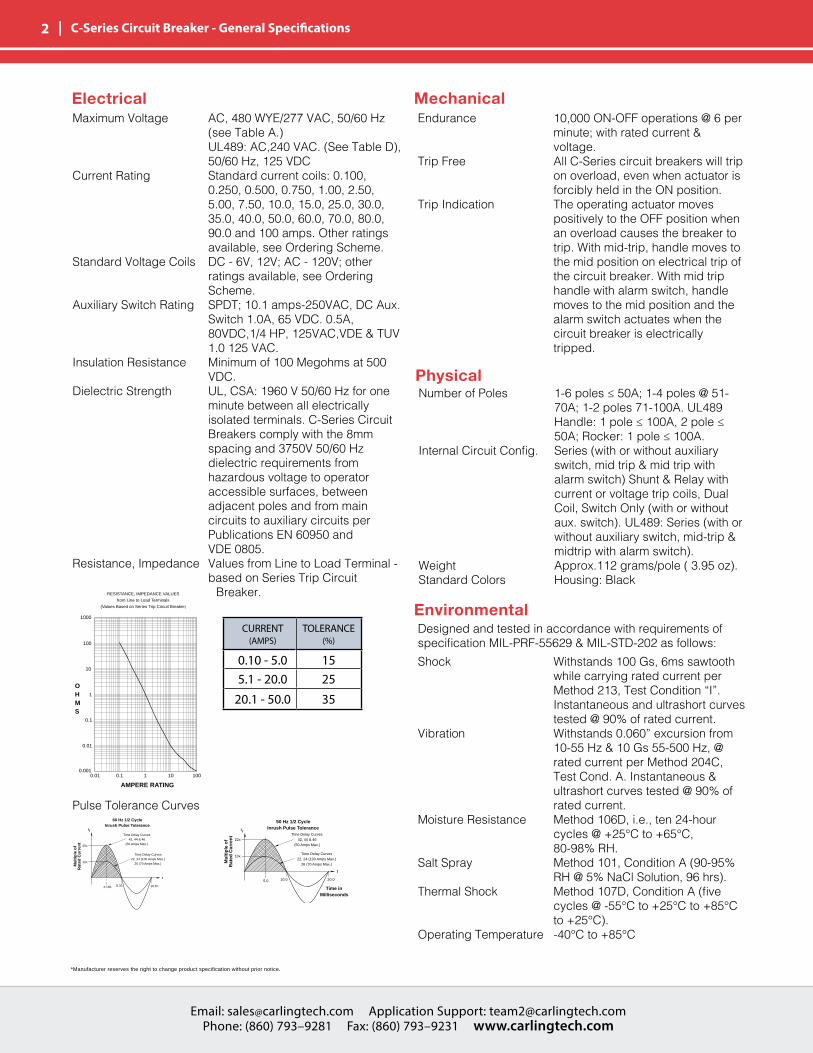
FIGURE 1
0.100 - 5.0
5.1 - 20.0
20.1 - 100
RESISTANCE, IMPEDANCE VALUES
from Line to Load Terminals
(Values Based on Series Trip Circuit Breaker)
AMPERE RATING
Time Delay Curves42, 44 & 46
(50 Amps Max.)
16.67
t
Mu
ltip
le o
fR
ated
Cu
rren
t
rI
4.165 8.33
25x
12x
20.0
Time Delay Curves22, 24 (100 Amps Max.)
26 (70 Amps Max.)
Time in Milliseconds
t
Time Delay Curves22, 24 (100 Amps Max.)
26 (70 Amps Max.)
60 Hz 1/2 CycleInrush Pulse Tolerance
50 Hz 1/2 CycleInrush Pulse Tolerance
10.0
Time Delay Curves42, 44 & 46
(50 Amps Max.)
22x
10x
Mu
ltip
le o
fR
ated
Cu
rren
t
5.0
rI
Time Delay Curves42, 44 & 46
(50 Amps Max.)
16.67
t
Mu
ltip
le o
fR
ated
Cu
rren
t
rI
4.165 8.33
25x
12x
20.0
Time Delay Curves22, 24 (100 Amps Max.)
26 (70 Amps Max.)
Time in Milliseconds
t
Time Delay Curves22, 24 (100 Amps Max.)
26 (70 Amps Max.)
60 Hz 1/2 CycleInrush Pulse Tolerance
50 Hz 1/2 CycleInrush Pulse Tolerance
10.0
Time Delay Curves42, 44 & 46
(50 Amps Max.)
22x
10x
Mu
ltip
le o
fR
ated
Cu
rren
t
5.0
rI
Maximum Voltage AC, 480 WYE/277 VAC, 50/60 Hz (see Table A.) UL489: AC,240 VAC. (See Table D), 50/60 Hz, 125 VDCCurrent Rating Standard current coils: 0.100, 0.250, 0.500, 0.750, 1.00, 2.50, 5.00, 7.50, 10.0, 15.0, 25.0, 30.0, 35.0, 40.0, 50.0, 60.0, 70.0, 80.0, 90.0 and 100 amps. Other ratings available, see Ordering Scheme.Standard Voltage Coils DC - 6V, 12V; AC - 120V; other ratings available, see Ordering Scheme.Auxiliary Switch Rating SPDT; 10.1 amps-250VAC, DC Aux. Switch 1.0A, 65 VDC. 0.5A, 80VDC,1/4 HP, 125VAC,VDE & TUV 1.0 125 VAC.Insulation Resistance Minimum of 100 Megohms at 500 VDC.Dielectric Strength UL, CSA: 1960 V 50/60 Hz for one minute between all electrically isolated terminals. C-Series Circuit Breakers comply with the 8mm spacing and 3750V 50/60 Hz dielectric requirements from hazardous voltage to operator accessible surfaces, between adjacent poles and from main circuits to auxiliary circuits per Publications EN 60950 and VDE 0805.Resistance, Impedance Values from Line to Load Terminal - based on Series Trip Circuit Breaker.
Endurance 10,000 ON-OFF operations @ 6 per minute; with rated current & voltage.Trip Free All C-Series circuit breakers will trip on overload, even when actuator is forcibly held in the ON position.Trip Indication The operating actuator moves positively to the OFF position when an overload causes the breaker to trip. With mid-trip, handle moves to the mid position on electrical trip of the circuit breaker. With mid trip handle with alarm switch, handle moves to the mid position and the alarm switch actuates when the circuit breaker is electrically tripped.
Number of Poles 1-6 poles ≤ 50A; 1-4 poles @ 51- 70A; 1-2 poles 71-100A. UL489 Handle: 1 pole ≤ 100A, 2 pole ≤ 50A; Rocker: 1 pole ≤ 100A.Internal Circuit Config. Series (with or without auxiliary switch, mid trip & mid trip with alarm switch) Shunt & Relay with current or voltage trip coils, Dual Coil, Switch Only (with or without aux. switch). UL489: Series (with or without auxiliary switch, mid-trip & midtrip with alarm switch).Weight Approx.112 grams/pole ( 3.95 oz).Standard Colors Housing: Black
Designed and tested in accordance with requirements of specification MIL-PRF-55629 & MIL-STD-202 as follows:Shock Withstands 100 Gs, 6ms sawtooth while carrying rated current per Method 213, Test Condition “I”. Instantaneous and ultrashort curves tested @ 90% of rated current.Vibration Withstands 0.060” excursion from 10-55 Hz & 10 Gs 55-500 Hz, @ rated current per Method 204C, Test Cond. A. Instantaneous & ultrashort curves tested @ 90% of rated current.Moisture Resistance Method 106D, i.e., ten 24-hour cycles @ +25°C to +65°C, 80-98% RH.Salt Spray Method 101, Condition A (90-95% RH @ 5% NaCl Solution, 96 hrs).Thermal Shock Method 107D, Condition A (five cycles @ -55°C to +25°C to +85°C to +25°C).Operating Temperature -40°C to +85°C
Pulse Tolerance Curves
CURRENT (AMPS)
TOLERANCE (%)
0.10 - 5.0 155.1 - 20.0 25
20.1 - 50.0 35

Email: [email protected] Application Support: [email protected] Phone: (860) 793–9281 Fax: (860) 793–9231 www.carlingtech.com
Email: [email protected] Application Support: [email protected] Phone: (860) 793–9281 Fax: (860) 793–9231 www.carlingtech.com
| 3 C-Series Circuit Breaker - General Specifications
Electrical TablesTable A: Lists UL Recognized & CSA Accepted configurations and performance capabilities as a Component Supplementary Protector
Notes:1. Requires branch circuit backup with a UL LISTED Type K5 or RK5 fuse rated 15A minimum and no more than 4 times full load amps not to exceed 125A for 50 Amp or less
rating and not to exceed 175 for 51 through 100 Amp rating
32 DC --- 0.02 - 100 --- --- 5000 TC1, OL1, U2 TC1, OL1, U2
48 DC --- 110 - 150 --- --- 5000 TC1, OL1, U2 TC1, OL1, U2
65 DC --- 0.02 - 70 --- --- 5000 TC1,2, OL1,U1 TC1,2, OL1,U1
--- 71 -100 --- 5000 TC1,2, OL0,U1 TC1,2, OL0,U1
0.02 - 70 --- --- 7500 TC1,2, OL1,U1 TC1,2, OL1,U1
--- 71 -100 --- 7500 TC1,2, OL0,U1 TC1,2, OL0,U1
0.02 - 70 --- --- 10,000 TC1,2, OL1,U1 TC1,2, OL1,U1 Must Have Agency Code "L"
--- 71 -100 --- 10,000 TC1,2, OL0,U1 TC1,2, OL0,U1 Must Have Agency Code "L"
125 DC --- 0.02 - 50 --- 5000 TC1,2,OL1,U1 TC1,2,OL1,U1 Must Have Agency Code "L"
125 / 250 DC --- 0.02 - 50 --- 5000 TC1,2,OL1,U1 TC1,2,OL1,U1 Must Have Agency Code "L"
250 DC --- 0.02 - 50 --- 5000 TC1,2,OL1,U1 TC1,2,OL1,U1 Must Have Agency Code "L". 2 Pole Break Required for 250 Volts
0.02 - 100 --- --- 3000 TC1, OL1, U2 TC1, OL1, U2 Per Pole Rating
0.02 - 100 --- --- 5000 TC1,2,OL1,U1 TC1,2,OL1,U1 Must Have Agency Code "L"
150 DC --- --- 80 - 100 --- 5000 TC1, OL0, U3 --- Must Have Agency Code "L"
150 DC --- --- 101 - 175 --- 5000 TC1, OL0, U3 --- Must Have Agency Code "L" Parallel Pole
0.02 - 100 --- --- 3500 TC1, OL1, U2 TC1, OL1, U2
0.02 - 50 --- --- 3000 TC1,2,OL1,U1 TC1,2,OL1,U1 2 or 3 poles breaking single phase
51 - 100 --- --- 1000 TC1,2,OL1,U1 TC1,2,OL1,U1 2 or 3 poles breaking single phase
0.02 - 100 --- --- 5000 TC1,2,OL1,U2 TC1,2,OL1,U2 2 or 3 poles breaking single phase, "L" Agency Code
0.02 - 50 --- --- 3500 TC1, OL1, U2 TC1, OL1, U2 Per Pole Rating
0.02 - 100 --- --- 5000 TC1,2,OL1,U1 TC1,2,OL1,U1 Must Have Agency Code "L"
51 - 70 --- 5000 --- TC1,2,OL1,C1 TC1,2,OL1,C1
--- 0.02 - 100 --- 3000 TC1, OL0, U2 TC1, OL0, U2
0.02 - 70 --- 5000 --- TC1,2,OL1,C1 TC1,2,OL1,C1 3 poles breaking 3 phase
--- 0.02 - 90 --- 5000 TC1,2,OL0,U1 TC1,2,OL0,U1 Must Have Agency Code "L"
277 50 / 60 1 0.02 - 50 --- 5000 --- TC1,2,OL1,C1 TC1,2,OL1,C1
0.02 - 30 --- 5000 --- TC1,2,OL1,C1 TC1,2,OL1,C1 3 poles breaking 3 phase
--- 31 - 50 5000 --- TC1,2,OL0,C1 TC1,2,OL0,C1
0.02 - 30 --- 5000 --- TC1,2,OL1,C1 TC1,2,OL1,C1 2 poles breaking 1 phase
--- 31 - 50 5000 --- TC1,2,OL0,C1 TC1,2,OL0,C1
80 DC --- 0.02 - 50 --- --- 7500 TC1,2, OL1,U1 TC1,2, OL1,U1
125 50 / 60 1 0.02 - 50 --- --- 3000 TC1, OL1, U2 TC1, OL1, U2 Per Pole Rating
0.02 - 50 --- --- 3500 TC1, OL1, U2 TC1, OL1, U2 2 or 3 poles breaking single phase
0.02 - 50 --- --- 3000 TC1,2,OL1,U1 TC1,2,OL1,U1 2 or 3 poles breaking single phase
1 0.02 - 50 --- --- 3500 TC1, OL1, U2 TC1, OL1, U2
0.02 - 50 --- --- 3000 TC1, OL0, U2 TC1, OL0, U2 Per Pole Rating
0.02 - 50 --- 5000 --- TC1,2,OL1,C1 TC1,2,OL1,C1
277 50 / 60 1 0.02 - 50 --- 5000 --- TC1,2,OL1,C1 TC1,2,OL1,C1 3 poles breaking 3 phase
80 DC --- 0.02 - 50 --- --- 7500 TC1,2, OL1,U1 TC1,2, OL1,U1
277 50 / 60 1 0.02 - 50 --- 5000 --- TC1,2,OL1,C1 TC1,2,OL1,C1
250 50 / 60 3 0.02 - 50 --- 5000 --- TC1,2,OL1,C1 TC1,2,OL1,C1 3 poles breaking 3 phase
0.02 - 30 --- 5000 --- TC1,2,OL1,C1 TC1,2,OL1,C1 3 poles breaking 3 phase
--- 31 - 50 5000 --- TC1,2,OL0,C1 TC1,2,OL0,C1
0.02 - 30 --- 5000 --- TC1,2,OL1,C1 TC1,2,OL1,C1 2 poles breaking 1 phase
--- 31 - 50 5000 --- TC1,2,OL0,C1 TC1,2,OL0,C1
80 DC --- 0.02 - 50 --- --- 7500 TC1,2, OL1,U1 TC1,2, OL1,U1
277 50 / 60 1 0.02 - 50 --- 5000 --- TC1,2,OL1,C1 TC1,2,OL1,C1
250 50 / 60 3 0.02 - 50 --- 5000 --- TC1,2,OL1,C1 TC1,2,OL1,C1 3 poles breaking 3 phase
0.02 - 70 --- --- --- --- ---
--- 71 -100 --- --- --- ---
0.02 - 70 --- --- --- --- ---
--- 71 -100 --- --- --- ---
125 50 / 60 1 0.02 - 100 --- --- --- --- ---
125 / 250 50 / 60 1 0.02 - 100 --- --- --- --- --- 2 or 3 poles breaking single phase
1 0.02 - 100 --- --- --- --- ---
3 0.02 - 70 --- --- --- --- ---
277 50 / 60 1 0.02 - 50 --- --- --- --- ---
0.02 - 30 --- --- --- --- --- 3 poles breaking 3 phase
--- 31 - 50 --- --- --- ---
125 / 250 50 / 60 1
DUAL COIL
C-SERIES TABLE A: COMPONENT SUPPLEMENTARY PROTECTORS
FULL LOAD AMPS
SERIES
CIRCUIT CONFIGURATION
MAX. RATING
FREQUENCY
50 / 60
250 50 / 60
1
3
480 50 / 60 1
480 / 277 50 / 60
125 / 250
1
3
3
480 50 / 60 1
480 / 277 50 / 60
3
GENERAL PURPOSE AMPS
DC
VOLTAGE
---80
80 DC
SHORT CIRCUIT CAPACITY (AMPS)
WITHOUT BACKUP FUSE
WITH BACKUP
FUSE 1
SWITCH ONLY
480 / 277 50 / 60
250 50 / 60
DC
CURRENT RATING
RELAY
SHUNT
3
65 DC
80
250 50 / 60
---
---
125 50 / 60 1
NOTES
UL CSA
APPLICATION CODES
---
PHASE
UL/CSA

Email: [email protected] Application Support: [email protected] Phone: (860) 793–9281 Fax: (860) 793–9231 www.carlingtech.com
4 | C-Series Circuit Breaker - General Specifications
Electrical TablesTable B: Lists UL Recognized and CSA Accepted configurations and performance capabilities as a Manual Motor Controller.
Table C: Lists UL Recognized, CSA Accepted, VDE and TUV Certified configurations and performance capabilities as a Component Supplementary Protector.
Notes:1 UL recognized and CSA Accepted at 480V refers to 3 & 4 pole versions used in a 3Ø, wye connected circuit or 2-pole version connected with 2 poles breaking. 1Ø and backed up with series fusing as stated above in note 1.* Series, Shunt and Relay Trip - Voltage Coil Construction not current coils
Notes:1. General Purpose ratings for UL/CSA only.2. Requires branch circuit backup with a UL LISTED Type K5 or RK5 fuse rated 15A minimum and no more than 4 times full load amps not to exceed 125A for 50 Amp or less
rating and not to exceed 175 for 51 through 100 Amp rating.
RELAY
Table D: Lists UL Listed (489), CSA Certified (C22.2 No. 5.1-M) configuration and performance capabilities as a Molded Case Circuit Breaker.
Notes from Table D: 1. Special catalog number required. Consult factory.
CURRENT RATING
INTERRUPTING CAPACITY
(AMPS)
50,000 1 Limited to 2 Poles Max from 71 - 100 Amps.
10,000 Limited to 2 Poles Max from 71 - 100 Amps.
125 DC --- 0.10 - 100 5,000 1 - 3 Poles
125 / 250 DC --- 0.10 - 50 5,000 1 or 2 Poles (2 Poles Required for 250 Volts)
0.10 - 50 10,000 1 - 3 Poles
51 - 70 5,000 1 - 3 Poles
0.10 - 50 5,000 2 or 3 Poles. 1 Pole of a 3 Pole Unit is Neutral
0.10 - 50 10000 1 2 or 3 Poles. 1 Pole of a 3 Pole Unit is Neutral
240 50 / 60 1 0.10 - 30 5,000 1Pole
240 50 / 60 1 0.10 - 20 5,000 2 Pole
277 50 / 60 1 0.10 - 20 10,000 1Pole
DUAL COIL 120 50 / 60 1 0.10 - 30 10,000 ---
CIRCUIT CONFIGURATION
FULL LOAD AMPS
PHASE
VOLTAGE
1
0.10 - 100
50 / 60 1120 / 240
DC
CONSTRUCTION NOTES
C SERIES TABLE D : UL489 LISTED BRANCH CIRCUIT BREAKERS
SERIES 120
80
50 / 60
WITHOUT BACKUP FUSE
MAX. RATING
FREQUENCY
---

Email: [email protected] Application Support: [email protected] Phone: (860) 793–9281 Fax: (860) 793–9231 www.carlingtech.com
Email: [email protected] Application Support: [email protected] Phone: (860) 793–9281 Fax: (860) 793–9231 www.carlingtech.com
| 5 C-Series Circuit Breaker - General Specifications
Electrical TablesTable E: Lists UL Recognized, CSA Accepted configurations and performance capabilities as Protectors, Supplementary for Marine Electrical and Fuel Systems (Guide PEQZ2, File E75596). Ignition Protected per UL 1500. UL Classified Small Craft Electrical Devices, Marine in accordance with ISO 8846 (Guide UZMK, File MQ1515) as Marine Supplementary Protectors.
Table F: Lists UL Listed configurations and performance capabilities as Circuit Breakers for use in Communications Equipment (Guide DITT, File E189195), under UL489A.
Agency CertificationsUL RecognizedUL Standard 1077
UL Standard 508
UL Standard 1500
UL ListedUL Standard 489
UL Standard 489A
CSA Accepted
CSA Certified
TUV Certified
VDE Certified
Component Recognition Program as Protectors Supplementary (Guide CCN/QVNU2, File E75596)
Switches, Industrial Control (Guide CCN/NRNT2, File E148683)
Protectors, Supplementary for Marine Electrical & Fuel Systems (Guide PEQZ2, File E75596) Ignition Protection
Circuit Breakers, Molded Case, (Guide DIVQ, File E129899)
Communications Equipment (Guide CCN/DITT, File E189195)
Component Supplementary Protector under Class 3215 30, FIle 047848 0 000 CSA Standard C22.2 No. 235
Circuit Breaker Model Case (Class 1432 01, File 093910), CSA Standard C22.2 No. 5.1 - M
EN60934, under License No. R72040875
EN60934, VDE 0642 under File No. 10537

Email: [email protected] Application Support: [email protected] Phone: (860) 793–9281 Fax: (860) 793–9231 www.carlingtech.com
6 | C-Series Circuit Breaker - Handle UL Recognized – Ordering Scheme
1Series
2Actuator
3Poles
5Aux/Alarm Switch
6Frequency& Delay
7Current Rating
8Terminal
9ActuatorColor
10MountingBezel/Barrier
11AgencyApproval
4 Circuit
C A B 1 13 0 2 C10 450
8 TERMINAL 15
1 10 Stud 10-32 6 12 Stud M62 11 Screw 10-32 7 13,15 0.250 Double Click Connect3 12 Stud 1/4-20 9 15 7/16” Clip Terminal4 11 Stud M5 x 0.8 A 14 Plug-In Stud5 11 Screw M5 x 0.8 C 11,15 5/16” Clip Terminal
5 AUXILIARY / ALARM SWITCH0 without Aux Switch2 S.P.D.T., 0.110 Q.C. Term.3 S.P.D.T., 0.139 Solder Lug4 S.P.D.T., 0.110 Q.C. Term. (Gold Contacts)
6 S.P.S.T., 0.139 Solder Lug8 S.P.S.T., 0.187 Q.C. Term.9 S.P.D.T., 0.187 Q.C. Term.
6 FREQUENCY & DELAY03 3 DC 50/60Hz, Switch Only 10 7 DC Instantaneous11 DC Ultra Short12 DC Short14 DC Medium16 DC Long20 7 50/60Hz Instantaneous21 50/60Hz Ultra Short22 50/60Hz Short24 50/60Hz Medium26 50/60Hz Long
30 DC 50/60Hz Instantaneous31 DC 50/60Hz Ultra Short32 DC 50/60Hz Short34 DC 50/60Hz Medium36 DC 50/60Hz Long42 8 50/60Hz Short, Hi-Inrush44 8 50/60Hz Medium, Hi-Inrush46 8 50/60Hz Long, Hi-Inrush52 8 DC Short, Hi-Inrush54 8 DC Medium, Hi-Inrush56 DC Long, Hi-Inrush
9 ACTUATOR COLOR & LEGEND 16
Actuator Color I-O ON-OFF Dual Legend ColorWhite A B 1 Black Black C D 2 WhiteRed F G 3 WhiteGreen H J 4 WhiteBlue K L 5 WhiteYellow M N 6 BlackGray P Q 7 BlackOrange R S 8 BlackBlack (short handle)17 T U 9 White
10 MOUNTING / BARRIERS MOUNTING STYLE BARRIERS VOLTAGE Threaded Insert1 6-32 x 0.195 inches no < 300A 6-32 X 0.195 inches yes < 300C 18 6-32X0.195inches yes ≥3002 ISO M3 x 5mm no < 300B ISO M3 x 5mm yes < 300D 18 ISOM3x5mm yes ≥300Front panel Snap-In, 1.00” [25.4mm] wide bezelE 17 with Handleguard no < 300
11 AGENCY APPROVALC UL Recognized, CSA AcceptedD VDECertified,ULRecognized,CSAAcceptedE TUVCertified,ULRecognized,CSAAcceptedH UL489Construction:VDECertified,ULRecognized,CSAAcceptedI UL Recognized STD 1077, UL Recognized 1500 (ignition protected), CSA AcceptedL UL489 Construction: UL Recognized, CSA AcceptedR UL489Construction:TUVCertified,ULRecognized,CSAAccepted
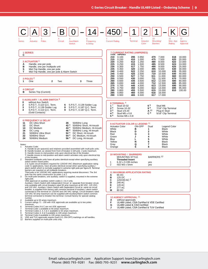
Notes:1 Actuator Code: A: Handle tie pin spacer(s) and retainers provided assembled with multi-pole units. B: Handle location as viewed from front of breaker: 2 pole - left pole 3 pole - center pole 4 pole - two handles at center poles 5 pole - three handles at center poles 6 pole - four handles at center poles S: Handle moves to mid-position only upon electrical trip of the breaker. Available with circuit codes B, C, D, E, F, G, H and K. T: Handle moves to mid-position and alarm switch activates only upon electrical trip of the breaker. Available with circuit codes B & C.2 Standard multipole units have all poles identical except when specifying auxiliary switch and/or mixed poles. 4 pole max with VDE. 5th pole available as Series Trip with Voltage Coil only.3 Switch Only circuits, rated up to 50 amps and 6 poles, and only available with VDE Certificationwhentiedtoaprotectedpole(CircuitCodeB,C,DorH.).For.02to 30 amps, select Current Code 630. For 35 - 50 amps, select Current Code 650. For 55-70 amps, select Current Code 670. For 75-100 amps, select Current Code 810.4 Circuit Codes D,E,F,G,H & K available with Terminal Codes 1,2,4 & 5 only. Circuit Codes D, F, H & K available up to 50 amps maximum Current Rating.5 Consult factory for available Dual Coil options, as special catalog number is required. Dual Coil Voltage Coils with Shunt Trip Construction trip instantaneously on line voltage. Dual Coil Voltage Coils require 30VA minimum power to trip instantaneously and are rated for intermittent duty only. 6 Auxiliary Switch available with Series Trip and Switch Only circuits. On multi-pole breakers, one auxiliary switch is supplied, mounted in the extreme right pole.7 Voltage coils not rated for continuous duty. Available only with delay codes 10 & 20.8 Available with Circuit Codes B & D only, and up to 50 amps maximum. 9 Current Ratings 60 - 70 are available up to four poles maximum. Ratings 71 - 100 are available up to two poles maximum.10 Terminal Code 1 available to 60 amps maximum.11 Terminal Codes 2, 4, 5 and C available to 50 amps maximum.12 Terminal Codes 3, 6 & 9 available to 100 amps maximum.13 Terminal Code 7 available to 25 amps maximum.14 Terminal Code A available to 100 amps maximum.15 Terminal Codes 7, 9 & C are not VDE approved.16 No marking available. Consult factory. VDE/TUV Approval requires dual (I-O, ON-OFF) or I-O markings on all handles. 17 Single pole only.18 VDE/TUV: 30 amps max.; UL/CSA: 50 amps max.; Available in 2 - 4 poles only and limited to AC Delays. “General Purpose amps” not rated for “full load amps” or to be used in applications with a motor.
1 SERIESC
2 ACTUATOR 1A Handle, one per poleB Handle, one per multipole unitS Mid-Trip Handle, one per poleT Mid-Trip Handle, one per pole & Alarm Switch
3 POLES 2 1 One2 Two
3 Three4 Four
5 Five6 Six
4 CIRCUIT 3A 3 Switch Only (No Coil)B Series Trip (Current)C Series Trip (Voltage)D 4 Shunt Trip (Current)E 4 Shunt Trip (Voltage)
F 4 Relay Trip (Current)G 4 Relay Trip (Voltage)H 4,5 Dual Coil with Shunt Trip Voltage CoilK 4,5 Dual Coil with Relay Trip Voltage Coil
7 CURRENT RATING (AMPERES)CODE AMPERES
OR VOLTAGE COIL (NORMAL RATED VOLTAGE) 7CODE AMPERES A06 6 DC A32 32 DC J12 12 AC J65 65 ACA12 12 DC A48 48 DC J18 18 AC K20 120 ACA18 18 DC A65 65 DC J24 24 AC L40 240 ACA24 24 DC J06 6 AC J48 48 AC
020 0.020025 0.025030 0.030035 0.035040 0.040045 0.045050 0.050055 0.055060 0.060065 0.065070 0.070075 0.075080 0.080085 0.085090 0.090095 0.095210 0.100215 0.150220 0.200225 0.250230 0.300
235 0.350240 0.400245 0.450250 0.500255 0.550260 0.600265 0.650270 0.700275 0.750280 0.800285 0.850290 0.900295 0.950410 1.000512 1.250415 1.500517 1.750420 2.000522 2.250425 2.500 527 2.750
430 3.000435 3.500440 4.000445 4.500450 5.000455 5.500460 6.000465 6.500470 7.000475 7.500480 8.000485 8.500490 9.000495 9.500610 10.000710 10.500611 11.000711 11.500612 12.000712 12.500613 13.000
614 14.000615 15.000616 16.000617 17.000618 18.000620 20.000622 22.000624 24.000625 25.000630 30.000635 35.000640 40.000650 50.000660 9 60.000670 9 70.000680 9 80.000685 9 85.000690 9 90.000695 9 95.000810 9 100.00

Email: [email protected] Application Support: [email protected] Phone: (860) 793–9281 Fax: (860) 793–9231 www.carlingtech.com
Email: [email protected] Application Support: [email protected] Phone: (860) 793–9281 Fax: (860) 793–9231 www.carlingtech.com
| 7 C-Series Circuit Breaker - Handle UL489A Listed / Parallel Pole – Ordering Scheme
9 ACTUATOR COLOR 2 LEGEND ON-OFF Dual Legend ColorWhite B 1 BlackBlack D 2 WhiteRed G 3 WhiteGreen J 4 WhiteBlue L 5 WhiteYellow N 6 BlackGray Q 7 BlackOrange S 8 Black
10 MOUNTING Threaded Insert1 6-32 x 0.195 inches2 ISO M3 x 5mm
12 AGENCY APPROVAL 6A Without ApprovalK UL489AListed,VDECertifiedT UL489A Listed7 UL489AListed,TUVCertified
1Series
2Actuator
3Poles
5Aux/Alarm Switch
6Frequency& Delay
7Current Rating
8Terminal
9ActuatorColor
10Mounting
11Max. App.Rating
12AgencyApproval
4 Circuit
C A P 3 12 0 2 M TD4 820
1 SERIESC
2 ACTUATORA Handle, one per poleS Mid-Trip Handle, one per pole 1T Mid-Trip, one per pole & Alarm Switch 1
8 TERMINAL 53 Stud 1/4-206 Stud M6A Plug-In Stud 3
3 POLES 4 1 One 2 Two 3 Three
4 CIRCUITP Series Trip (parallel pole)
6 FREQUENCY & DELAYD1 DC Ultra ShortD2 DC ShortD4 DC MediumD6 DC Long
11 MAXIMUM APPLICATION RATINGM 80 DC
Notes:1 Handle moves to Mid-Position only upon electrical trip of C/B when Actuator S is specified.WhenActuatorCodeTisspecified,handlemovestoMidPositionand Alarm Switch actuates only upon electrical trip of C/B. Code T is only available with Circuit Code N.2 Standard Handle colors are White, Black, Red & Yellow. 3 Breakers with Terminal Codes 3 & 6 are supplied with bus bars connecting the Line and Load Terminals. For Terminal Code A, Line and Load Terminals must be connected to a copper bus bar having a minimum cross-section of 0.078 square inches. Terminal code A not available on the single pole unit.4 Ratings for 101 to 125 amps are available in 1-pole size. Ratings from 110 to 200 amps are available in 2-pole size. For ratings from 225-250 amps, specify 3-pole size. For ratings from 350-400 amps, specify 4-pole size.5 1 pole only available with terminal codes 3 and 6.6 Agency codes K and 7 not available with 1 pole. Agency code J only available with 1 pole.
5 AUXILIARY / ALARM SWITCH0 without Aux Switch2 S.P.D.T., 0.110 Q.C. Term.3 S.P.D.T., 0.139 Solder Lug4 S.P.D.T., 0.110 Q.C. Term. (Gold Contacts)5 S.P.S.T., N.O., 0.110 Q.C Term. (Gold Contacts)
6 S.P.S.T., 0.139 Solder Lug7 S.P.S.T., 0.110 Q.C Term. (Gold Contacts)8 S.P.S.T., 0.187 Q.C. Term.9 S.P.D.T., 0.187 Q.C. Term.
7 CURRENT RATING (AMPERES) 4CODE AMPERES 810 100.00811 110.00812 120.00912 125.00
813 130.00814 140.00815 150.00816 160.00
817 170.00917 175.00818 180.00819 190.00
820 200.00922 225.00825 250.00

Email: [email protected] Application Support: [email protected] Phone: (860) 793–9281 Fax: (860) 793–9231 www.carlingtech.com
8 | C-Series Circuit Breaker - Rocker UL489A Listed / Parallel Pole – Ordering Scheme
9 ACTUATOR COLOR LEGEND ON-OFF Dual Legend ColorWhite B 1 BlackBlack D 2 WhiteRed G 3 WhiteGreen J 4 WhiteBlue L 5 WhiteYellow N 6 BlackGray Q 7 BlackOrange S 8 Black
10 MOUNTING ROCKER / MOUNTING INSERT STYLE A Standard Rocker Bezel - 6-32 InsertsB Standard Rocker Bezel - M3 InsertsC Rocker Guard Bezel - 6-32 InsertsD Rocker Guard Bezel - M3 InsertsE Standard Bezel with recessed Off Side Flat Rocker - 6-32 InsertsF Standard Bezel with recessed Off Side Flat Rocker - M3 InsertsG Push to Reset Bezel - 6-32 InsertsH Push to Reset Bezel - M3 Inserts
12 AGENCY APPROVAL 4A Without ApprovalT UL489A Listed7 UL489AListed,TUVCertified
1Series
2Actuator
3Poles
5Aux/Alarm Switch
6Frequency& Delay
7Current Rating
8Terminal
9ActuatorColor
10Mounting
11Max. App.Rating
12AgencyApproval
4 Circuit
C 1 P 3 A2 0 2 M TD4 820
1 SERIESC
2 ACTUATORC Curved Rocker, Two Color Visi, Indicate On, Vertical LegendD Curved Rocker, Two Color Visi, Indicate On, Horizontal LegendF Curved Rocker, Two Color Visi, Indicate Off, Vertical LegendG Curved Rocker, Two Color Visi, Indicate Off, Horizontal LegendJ Curved Rocker, Single Color, Vertical LegendK Curved Rocker, Single Color, Horizontal LegendN Curved Rocker, Push To Reset, Two Color Visi, Vertical LegendO Curved Rocker, Push To Reset, Two Color Visi, Horizontal Legend1 Flat Rocker, Two Color Visi, Vertical Legend2 Flat Rocker, Two Color Visi, Horizontal Legend3 Flat Rocker, Single Color, Vertical Legend4 Flat Rocker, Single Color, Horizontal Legend5 Flat Rocker, Push To Reset, Two Color Visi, Vertical Legend6 Flat Rocker, Push To Reset, Two Color Visi, Horizontal Legend7 Flat Rocker, Push To Reset, Single Color, Vertical Legend8 Flat Rocker, Push To Reset, Single Color, Horizontal Legend
8 TERMINAL 33 Stud 1/4-206 Stud M6A Plug-In Stud 1
3 POLES 2 1 One 2 Two 3 Three
4 CIRCUITP Series Trip (parallel pole)
6 FREQUENCY & DELAYD1 DC Ultra ShortD2 DC ShortD4 DC MediumD6 DC Long
11 MAXIMUM APPLICATION RATINGM 80 DC
Notes:1 Breakers with Terminal Codes 3 & 6 are supplied with bus bars connecting the Line and Load Terminals. For Terminal Code A, Line and Load Terminals must be connected to a copper bus bar having a minimum cross-section of 0.078 square inches. Terminal code A not available on the single pole unit.2 Ratings for 101 to 125 amps are available in 1-pole size. Ratings from 110 to 200 amps are available in 2-pole size. For ratings from 225-250 amps, specify 3-pole size. For ratings from 350-400 amps, specify 4-pole size.3 1 pole only available with terminal codes 3 and 6.4 Agency codes K and 7 not available with 1 pole. Agency code J only available with 1 pole.
5 AUXILIARY/ALARM SWITCH0 without Aux Switch2 S.P.D.T., 0.110 Q.C. Term.3 S.P.D.T., 0.139 Solder Lug4 S.P.D.T., 0.110 Q.C. Term. (Gold Contacts)5 S.P.S.T., N.O., 0.110 Q.C Term. (Gold Contacts)
6 S.P.S.T., 0.139 Solder Lug7 S.P.S.T., 0.110 Q.C Term. (Gold Contacts)8 S.P.S.T., 0.187 Q.C. Term.9 S.P.D.T., 0.187 Q.C. Term.
7 CURRENT RATING (AMPERES) 2CODE AMPERES 810 100.00811 110.00812 120.00912 125.00
813 130.00814 140.00815 150.00816 160.00
817 170.00917 175.00818 180.00819 190.00
820 200.00922 225.00825 250.00
Email: [email protected] Application Support: [email protected] Phone: (860) 793–9281 Fax: (860) 793–9231 www.carlingtech.com
Email: [email protected] Application Support: [email protected] Phone: (860) 793–9281 Fax: (860) 793–9231 www.carlingtech.com
| 9 C-Series Circuit Breaker - Handle UL489 Listed – Ordering Scheme
1Series
2Actuator
3Poles
5Aux/Alarm Switch
6Frequency& Delay
7Current Rating
8Terminal
9ActuatorColor
10Mounting/Barriers
11Max. App.Rating
12AgencyApproval
4 Circuit
C A B 1 13 0 2 K G14 450
11 MAXIMUM APPLICATION RATINGA 65 DCB 125 DCC 120/240 AC 2D 240 ACK 120 ACF 277 ACM 80 DC
Notes:1 Actuator Code: A: Handle tie pin spacer(s) and retainers provided assembled with multi-pole units. B: Handle located, as viewed from front of breaker in left pole. 2 pole maximum. S: Handle moves to mid-position only upon electrical trip of the breaker. T: Handle moves to mid-position and alarm switch activates only upon electrical trip of the breaker. 2 Standard multipole units have all poles identical except when specifying auxiliary switch and/or mixed poles. 2 & 3 pole circuit breakers required for 120/240 VAC (Maximum application rating code C) applications, have all poles identical except when specifying auxiliary / alarmswitchwhichisnormallysuppliedinextremerightpoleperfigureB.Terminal barriers are required on all multipole breakers. Third pole is for 120/240 VAC applications requiring neutral disconnect. The 3rd pole has the same construction as poles 1 & 2.3 On multi-pole breakers, one auxiliary. switch is supplied, mounted in the extreme right pole. VDE approval on auxiliary switch codes 2, 3 & 4 only. Auxiliary / Alarm Switch with Independent Circuit ie: separate from breaker circuit, only available with circuit breakers rated 50 amp maximum at 80 VDC, 125 VDC, and 120 VAC. Auxiliary / Alarm Switch with Dependent Circuit ie: same as circuit breaker, is supplied from factory with common terminal of auxiliary / alarm switch connected to line terminal on 120/240 and 240 VAC ratings. Circuit breakers rated 120 VAC 50 amp maximum can be supplied with Auxiliary/Alarm switch common terminal connected to breaker line terminal. Consult factory for special catalog number.4 Available up to 50 amps maximum. 5 Current ratings 71 - 100 with VDE approvals are available up to two poles maximum.6 Terminal Codes 9 & C are not VDE approved.7 Terminal Code 1 available to 60 amps maximum.8 Terminal Codes 2, 4, 5 & C available to 50 amps maximum.9 Terminal Codes 3, 6 & 9 available to 100 amps maximum.10 Terminal Code A available to 100 amps maximum.11 VDE and TUV approvals require Dual (I-O, ON-OFF) markings on all handles.12 Barriers supplied on multi-pole units only.
10 MOUNTING / BARRIERS MOUNTING STYLE BARRIERS 12 Threaded Insert1 6-32 x 0.195 inches yes2 ISO M3 x 5mm yes
12 AGENCY APPROVAL 11
A without approvalsF UL489Listed,CSACertified&VDECertifiedG UL489Listed&CSACertifiedJ UL489Listed,CSACertified&TUVCertified
8 TERMINAL 61 7 Stud 10-32 6 9 Stud M62 8 Screw 10-32 9 9 7/16” Clip Terminal3 9 Stud 1/4-20 A 10 Plug-In Stud4 8 Stud M5 x 0.8 C 8 5/16” Clip Terminal5 8 Screw M5 x 0.8
5 AUXILIARY / ALARM SWITCH 30 without Aux Switch2 S.P.D.T., 0.110 Q.C. Term. 6 S.P.S.T., 0.139 Solder Lug3 S.P.D.T., 0.139 Solder Lug 8 S.P.S.T., 0.187 Q.C. Term.4 S.P.D.T., 0.110 Q.C. Term. 9 S.P.D.T., 0.187 Q.C. Term. (Gold Contacts)
6 FREQUENCY & DELAY11 DC Ultra Short12 DC Short14 DC Medium16 DC Long21 50/60Hz Ultra Short22 50/60Hz Short24 50/60Hz Medium
26 50/60Hz Long42 4 50/60Hz Short, Hi-Inrush44 4 50/60Hz Medium, Hi-Inrush46 4 50/60Hz Long, Hi-Inrush52 4 DC Short, Hi-Inrush54 4 DC Medium, Hi-Inrush56 4 DC Long, Hi-Inrush
9 ACTUATOR COLOR & LEGEND 11
Actuator Color ON-OFF Dual Legend ColorWhite B 1 Black Black D 2 WhiteRed G 3 WhiteGreen J 4 WhiteBlue L 5 WhiteYellow N 6 BlackGray Q 7 BlackOrange S 8 Black
1 SERIESC
2 ACTUATOR 1A Handle, one per poleB Handle, one per multipole unitS Mid-Trip Handle, one per poleT Mid-Trip Handle, one per pole & Alarm Switch
3 POLES 2 1 One 2 Two 3 Three
4 CIRCUITB Series Trip (Current)
7 CURRENT RATING (AMPERES)CODE AMPERES
210 0.100215 0.150220 0.200225 0.250230 0.300235 0.350240 0.400245 0.450250 0.500255 0.550260 0.600265 0.650270 0.700275 0.750280 0.800285 0.850290 0.900
295 0.950410 1.000512 1.250415 1.500517 1.750420 2.000522 2.250425 2.500 527 2.750430 3.000435 3.500440 4.000445 4.500450 5.000455 5.500460 6.000465 6.500
470 7.000475 7.500480 8.000485 8.500490 9.000495 9.500610 10.000710 10.500611 11.000711 11.500612 12.000712 12.500613 13.000614 14.000615 15.000616 16.000617 17.000
618 18.000620 20.000622 22.000624 24.000625 25.000630 30.000635 35.000640 40.000660 60.000670 70.000680 80.000685 85.000690 90.000695 95.000810 100.00

Email: [email protected] Application Support: [email protected] Phone: (860) 793–9281 Fax: (860) 793–9231 www.carlingtech.com
10 | C-Series Circuit Breaker - Sealed Toggle UL Recognized – Ordering Scheme
1Series
2Actuator
3Poles
5Aux/Alarm Switch
6Frequency& Delay
7Current Rating
8Terminal
9LegendPlate
10MountingBezel/Barrier
11AgencyApproval
4 Circuit
C M B 1 13 0 0 C10 450
1 SERIESC
2 ACTUATOR 1M Sealed Toggle, one per pole
3 POLES1 One 2 Two 3 Three
4 CIRCUITA 2 Switch Only (no coil)B Series Trip (current)C Series Trip (voltage)D 3 Shunt Trip (current)E 3 Shunt Trip (voltage)
F 3 Relay Trip (current)G 3 Relay Trip (voltage)H 3,4 Dual Coil with Shunt Trip Voltage CoilK 3,4 Dual Coil with Relay Trip Voltage Coil
9 LEGEND PLATE0 No Legend
Notes:1 Actuator Code M: Handle location as viewed from front of breaker: 2 pole - right pole 3 pole - center pole2 Switch Only circuits, rated up to 50 amps and 3 poles, and only available with VDE. For .02 to 30 amps, select Current Code 630. For 35 - 50 amps, select Current Code 650. For 55-70 amps, select Current Code 670. For 75-100 amps, select Current Code 810.3 Circuit Codes D,E,F,G,H & K available with Terminal Codes 1,2,4 & 5 only. 4 Consult factory for available Dual Coil options, as special catalog number is required. Dual Coil Voltage Coils with Shunt Trip Construction trip instantaneously on line voltage. Dual Coil Voltage Coils require 30VA minimum power to trip instantaneously and are rated for intermittent duty only. 5 Auxiliary Switch available with Series Trip and Switch Only circuits. On multi-pole breakers, one auxiliary switch is supplied, mounted in the extreme right pole.6 Voltage coils not rated for continuous duty. Available only with delay codes 10 & 20.7 Available with Circuit Codes B & D only, and up to 50 amps maximum. 8 Consult factory for current ratings 71-100, in three pole units, available as special catalog number only.9 Terminal Code 1 available to 60 amps maximum.10 Terminal Codes 2, 4, 5 and C available to 50 amps maximum.11 Terminal Codes 3, 6 & 9 available to 100 amps maximum.12 Terminal Code 7 available to 25 amps maximum.13 Terminal Code A available to 100 amps maximum.
10 MOUNTING / BARRIERS MOUNTING STYLE BARRIERS1 Standard Hex Nut noA Standard Hex Nut (multi-pole units only) yes
11 AGENCY APPROVALC UL Recognized & CSA AcceptedI UL Recognized & CSA Accepted, UL1500 ignition protectionL UL Recognized & CSA Accepted with listed construction
5 AUXILIARY / ALARM SWITCH0 without Aux Switch2 S.P.D.T., 0.110 Q.C. Term.3 S.P.D.T., 0.139 Solder Lug4 S.P.D.T., 0.110 Q.C. Term. (Gold Contacts)
6 S.P.S.T., 0.139 Solder Lug8 S.P.S.T., 0.187 Q.C. Term.9 S.P.D.T., 0.187 Q.C. Term.
8 TERMINAL1 9 Stud 10-32 6 11 Stud M62 10 Screw 10-32 7 12 0.250 Double Click Connect3 11 Stud 1/4-20 9 11 7/16” Clip Terminal4 10 Stud M5 x 0.8 A 13 Plug-In Stud5 10 Screw M5 x 0.8 C 10 5/16” Clip Terminal
6 FREQUENCY & DELAY03 2 DC 50/60Hz, Switch Only 10 6 DC Instantaneous11 DC Ultra Short12 DC Short14 DC Medium16 DC Long20 6 50/60Hz Instantaneous21 50/60Hz Ultra Short22 50/60Hz Short24 50/60Hz Medium26 50/60Hz Long
30 DC 50/60Hz Instantaneous31 DC 50/60Hz Ultra Short32 DC 50/60Hz Short34 DC 50/60Hz Medium36 DC 50/60Hz Long42 7 50/60Hz Short, Hi-Inrush44 7 50/60Hz Medium, Hi-Inrush46 7 50/60Hz Long, Hi-Inrush52 7 DC Short, Hi-Inrush54 7 DC Medium, Hi-Inrush56 DC Long, Hi-Inrush
7 CURRENT RATING (AMPERES) 9CODE AMPERES
OR VOLTAGE COIL (NORMAL RATED VOLTAGE) 7CODE AMPERES A06 6 DC A32 32 DC J12 12 AC J65 65 ACA12 12 DC A48 48 DC J18 18 AC K20 120 ACA18 18 DC A65 65 DC J24 24 AC L40 240 ACA24 24 DC J06 6 AC J48 48 AC
020 0.020025 0.025030 0.030035 0.035040 0.040045 0.045050 0.050055 0.055060 0.060065 0.065070 0.070075 0.075080 0.080085 0.085090 0.090095 0.095210 0.100215 0.150220 0.200225 0.250230 0.300
235 0.350240 0.400245 0.450250 0.500255 0.550260 0.600265 0.650270 0.700275 0.750280 0.800285 0.850290 0.900295 0.950410 1.000512 1.250415 1.500517 1.750420 2.000522 2.250425 2.500 527 2.750
430 3.000435 3.500440 4.000445 4.500450 5.000455 5.500460 6.000465 6.500470 7.000475 7.500480 8.000485 8.500490 9.000495 9.500610 10.000710 10.500611 11.000711 11.500612 12.000712 12.500613 13.000
614 14.000615 15.000616 16.000617 17.000618 18.000620 20.000622 22.000624 24.000625 25.000630 30.000635 35.000640 40.000650 50.000660 9 60.000670 9 70.000680 9 80.000685 9 85.000690 9 90.000695 9 95.000810 9 100.00

Email: [email protected] Application Support: [email protected] Phone: (860) 793–9281 Fax: (860) 793–9231 www.carlingtech.com
Email: [email protected] Application Support: [email protected] Phone: (860) 793–9281 Fax: (860) 793–9231 www.carlingtech.com
| 11 C-Series Circuit Breaker - Rocker UL Recognized – Ordering Scheme
2 ACTUATOR 1Two Color Visi-RockerC Indicate ON, vertical legendD Indicate ON, horizontal legendE Indicate ON, no legendF Indicate OFF, vertical legendG Indicate OFF, horizontal legendH Indicate OFF, no legendPush-To-Reset, Visi-RockerN Indicate OFF, vertical legendO Indicate OFF, horizontal legendP Indicate OFF, no legendSingle colorJ Vertical legendK Horizontal legendL No legendPush-To-Reset, Single colorR Vertical legendU Horizontal legendV No legend
1Series
2Actuator
3Poles
5Aux/Alarm Switch
6Frequency& Delay
7Current Rating
8Terminal
9ActuatorColor
10Mounting/Barriers
11AgencyApproval
4 Circuit
C C B 1 13 0 2 D14 450
1 SERIESC
8 TERMINAL1 10 Stud 10-32 6 12 Stud M62 11 Screw 10-32 7 13 0.250 Double Quick Connect3 12 Stud 1/4-20 9 7/16” Clip Terminal4 11 Stud M5 x 0.8 A 14 Plug-In Stud5 11 Screw M5 x 0.8 C 5/16” Clip Terminal
3 POLES 21 One 2 Two 3 Three
9 ACTUATOR COLOR & LEGEND 16,17,18
Actuator orVisi-Color Marking: Marking Color: Single ColorColor: I-O ON-OFF Dual/None Rocker/Handle Visi-Rocker White A B 1 Black WhiteBlack C D 2 White n/aRed F G 3 White RedGreen H J 4 White GreenBlue K L 5 White BlueYellow M N 6 Black YellowGray P Q 7 Black GrayOrange R S 8 Black Orange
6 FREQUENCY & DELAY03 DC 50/60Hz, Switch Only 10 7 DC Instantaneous11 DC Ultra Short12 DC Short14 DC Medium16 DC Long20 7 50/60Hz Instantaneous21 50/60Hz Ultra Short22 50/60Hz Short24 50/60Hz Medium26 50/60Hz Long
30 DC 50/60Hz Instantaneous31 DC 50/60Hz Ultra Short32 DC 50/60Hz Short34 DC 50/60Hz Medium36 DC 50/60Hz Long42 8 50/60Hz Short, Hi-Inrush44 8 50/60Hz Medium, Hi-Inrush46 8 50/60Hz Long, Hi-Inrush52 8 DC Short, Hi-Inrush54 8 DC Medium, Hi-Inrush56 8 DC Long, Hi-Inrush
Notes:1 Push-To-Reset actuators have OFF portion of rocker shrouded.2 Multi-pole breakers have all poles identical except when specifying Auxiliary switch and/or mixed poles, and have one rocker per breaker. Rocker location as viewed from front panel: 2 pole – left pole; 3 pole – center pole.3 Switch Only circuits, rated up to 50 amps and 3 poles, and only available with VDE Certificationwhentiedtoaprotectedpole(CircuitCodeB,C,DorH.),For.02to 30 amps, select Current Code 630. For 35 - 50 amps, select Current Code 650. For 55-70 amps, select Current Code 670. For 75-100 amps, select Current Code 810.4 Circuit Codes D,E,F,G,H & K available with Terminal Codes 1,2,4 & 5 only. Circuit Codes D,F,H & K available up to 50 amps maximum Current Rating. 5 Consult factory for available Dual Coil options, as special catalog number is required. Dual Coil Voltage Coils with Shunt Trip Construction trip instantaneously on line voltage. Dual Coil Voltage Coils require 30VA minimum power to trip instantaneously and are rated for intermittent duty only. 6 Auxiliary Switch available with Series Trip and Switch Only circuits. On multi-pole breakers, one auxiliary switch is supplied, mounted in the extreme right pole. Auxiliary switch codes 2, 3 & 4 are VDE approved.7 Voltage coils not rated for continuous duty. Available only with delay codes 10 & 20.8 Available with Circuit Codes B & D only, and up to 50 amps maximum. 9 Current Ratings 60-70 are available up to four poles maximum. Ratings 71-100 are available up to two poles maximum.10 Terminal Code 1 available to 60 amps maximum.11 Terminal Codes 2,4,5 & C available to 50 amps maximum.12 Terminal Codes 3,6 & 9 available to 100 amps maximum.13 Terminal Code 7 available to 25 amps maximum.14 Terminal Code A available to 100 amps maximum.15 Terminal Codes 7, 9 & C are not VDE approved.16 Color shown is visi and legend with remainder of rocker black17 Legend on Push-to-reset bezel/shroud is white when single color rocker is ordered. Dual = ON-OFF/I-O legend with actuator codes C - G, and J, K, N, O, R, & U. None = no legend with actuator codes H, L, P, V. Rockerguard available with actuator codes C - L. Push-to-reset available with actuator codes N, O, P, R, U, V.18 VDE/TUV approval requires Dual (I-O, ON-OFF) or I-O markings on rocker.19 VDE/TUV: 30 amps max.; UL/CSA: 50 amps max.; Available in 2 - 4 poles only and limited to AC Delays. “General Purpose amps” not rated for “full load amps” or to be used in applications with a motor.
10 MOUNTING / BARRIERS 1 STANDARD ROCKER BEZEL BARRIERS VOLTAGE1 6-32 x 0.195 inches no <3002 6-32 x 0.195 inches yes <3003 19 6-32x0.195inches yes ≥3004 ISO M3 x 5mm no <3005 ISO M3 x 5mm yes <300 6 19 ISOM3x5mm yes ≥300 ROCKERGUARD BEZEL A 6-32 x 0.195 inches no <300C 6-32 x 0.195 inches yes <300E 19 6-32x0.195inches yes ≥300G ISO M3 x 5mm no <300J ISO M3 x 5mm yes <300L 19 ISOM3x5mm yes ≥300 PUSH-TO-RESET BEZEL B 6-32 x 0.195 inches no <300D 6-32 x 0.195 inches yes <300F 19 6-32x0.195inches yes ≥300H ISO M3 x 5mm no <300J ISO M3 x 5mm yes <300M 19 ISOM3x5mm yes ≥300
11 AGENCY APPROVALC UL Recognized & CSA AcceptedD VDECertified,ULRecognized&CSAAcceptedE TUVCertified,ULRecognized&CSAAcceptedH UL489Construction:VDECertified,ULRecognized&CSAAcceptedI UL Recognized STD 1077, UL Recognized 1500 (ignition protected), & CSA AcceptedL UL489 Construction: UL Recognized & CSA AcceptedR UL489Construction:TUVCertified,ULRecognized&CSAAccepted
4 CIRCUIT F 4 Relay Trip (Current)A 3 Switch Only (No Coil) G 4 Relay Trip (Voltage)B Series Trip (Current) H 4,5 Dual Coil with Shunt TripC Series Trip (Voltage) Voltage CoilD 4 Shunt Trip (Current) K 4,5 Dual Coil with Relay TripE 4 Shunt Trip (Voltage) Voltage Coil
7 CURRENT RATING (AMPERES)CODE AMPERES
OR VOLTAGE COIL (NORMAL RATED VOLTAGE) 7CODE AMPERES A06 6 DC A32 32 DC J12 12 AC J65 65 ACA12 12 DC A48 48 DC J18 18 AC K20 120 ACA18 18 DC A65 65 DC J24 24 AC L40 240 ACA24 24 DC J06 6 AC J48 48 AC
020 0.020025 0.025030 0.030035 0.035040 0.040045 0.045050 0.050055 0.055060 0.060065 0.065070 0.070075 0.075080 0.080085 0.085090 0.090095 0.095210 0.100215 0.150220 0.200225 0.250230 0.300
235 0.350240 0.400245 0.450250 0.500255 0.550260 0.600265 0.650270 0.700275 0.750280 0.800285 0.850290 0.900295 0.950410 1.000512 1.250415 1.500517 1.750420 2.000522 2.250425 2.500 527 2.750
430 3.000435 3.500440 4.000445 4.500450 5.000455 5.500460 6.000465 6.500470 7.000475 7.500480 8.000485 8.500490 9.000495 9.500610 10.000710 10.500611 11.000711 11.500612 12.000712 12.500613 13.000
614 14.000615 15.000616 16.000617 17.000618 18.000620 20.000622 22.000624 24.000625 25.000630 30.000635 35.000640 40.000650 50.000660 9 60.000670 9 70.000680 9 80.000685 9 85.000690 9 90.000695 9 95.000810 9 100.00
5 AUXILIARY / ALARM SWITCH 60 without Aux Switch2 S.P.D.T., 0.110 Q.C. Term. 6 S.P.S.T., 0.139 Solder Lug3 S.P.D.T., 0.139 Solder Lug 8 S.P.S.T., 0.187 Q.C. Term.4 S.P.D.T., 0.110 Q.C. Term. 9 S.P.D.T., 0.187 Q.C. Term. (Gold Contacts)

Email: [email protected] Application Support: [email protected] Phone: (860) 793–9281 Fax: (860) 793–9231 www.carlingtech.com
12 | C-Series Circuit Breaker - Rocker UL Listed – Ordering Scheme
8 TERMINAL1 5 Stud 10-32 6 7 Stud M62 6 Screw 10-32 with saddle 9 7,8 7/16” Clip Terminal & washer clamps A 7,8 Plug-In Stud3 7 Stud 1/4-20 C 6,8 5/16” Clip Terminal4 6 Stud M5 x 0.8 5 6 Screw M5 x 0.8 with saddle & washer clamps
9 ACTUATOR COLOR & LEGEND 11
Actuator orVisi-Color Marking: Marking Color: Single ColorColor: ON-OFF Dual 10 Rocker/Handle Visi-Rocker White B 1 Black WhiteBlack D 2 White n/aRed G 3 White RedGreen J 4 White GreenBlue L 5 White BlueYellow N 6 Black YellowGray Q 7 Black GrayOrange S 8 Black Orange
2 ACTUATOR 1Two Color Visi-Rocker Single colorC Indicate ON, vertical legend J Vertical legendD Indicate ON, horizontal legend K Horizontal legendF Indicate OFF, vertical legendG Indicate OFF, horizontal legend
SINGLE COLOR
CODE "J"
LINE
CODE "K"
LINE
INDICATE "ON"
CODE "C"LINE
LINELINE
LINE
CODE "D"
INDICATECOLORLOCATION
HO
RIZ
ON
TAL
ST
YL
EV
ER
TIC
AL
ST
YL
E
CODE "G"
CODE "F"
ROCKER STYLE DESCRIPTIONSINDICATE "OFF"
1Series
2Actuator
3Poles
5Aux/Alarm Switch
6Frequency& Delay
7Current Rating
8Terminal
9ActuatorColor
10Mounting/Barriers
11Max. App.Rating
12AgencyApproval
4 Circuit
C C B 1 A3 0 2 K G14 450
1 SERIESC
3 POLES 11 One 2 Two 3 Three
4 CIRCUITB Series Trip (current)
11 MAXIMUM APPLICATION RATINGA 65 DCB 125 DCC 120/240 AC 14
D 240 ACF 277 ACK 120 ACM 80 DC
6 FREQUENCY & DELAY11 DC Ultra Short12 DC Short14 DC Medium16 DC Long21 50/60Hz Ultra Short22 50/60Hz Short24 50/60Hz Medium26 50/60Hz Long
42 8 50/60Hz Short, Hi-Inrush44 8 50/60Hz Medium, Hi-Inrush46 8 50/60Hz Long, Hi-Inrush52 8 DC Short, Hi-Inrush54 8 DC Medium, Hi-Inrush56 DC Long, Hi-Inrush
Notes:1 Multi-pole breakers have all breakers identical except when specifying Auxiliary switch and/or mixed poles, and have one rocker per breaker.2 On multi-pole breakers, one auxiliary switch is supplied, mounted in the extreme right pole.3 Available up to 50 amps maximum. 4 Current ratings 71 - 100 with VDE approvals are available up to two poles maximum.5 Terminal Code 1 available to 60 amps maximum.6 Terminal Codes 2, 4, 5 & C available to 50 amps maximum.7 Terminal Codes 3, 6, 9 & A available to 100 amps maximum.8 Terminal Codes 9 & C are not VDE approved.9 Color shown is visi and legend with remainder of rocker black10 Dual = ON-OFF/I-O legend on actuator.11 VDE and TUV approval requires Dual (I-O, ON-OFF) markings on rocker.12 Rockerguard available with all actuator codes. 13 Barriers supplied on multi-pole units only.14 2 & 3 pole circuit breakers required for 120/240 AC rating.
10 MOUNTING / BARRIERS 12
Standard Rocker Bezel BARRIERS 13
Threaded Insert, 2 per poleA 6-32 X 0.195 inches yesC ISO M3 x 5mm yes Rockerguard Bezel Threaded Insert, 2 per poleB 6-32 x 0.195 inches yesD ISO M3 x 5mm yes
12 AGENCY APPROVALA without approvalsF UL489Listed,CSACertified,&VDECertifiedG UL489Listed&CSACertifiedJ UL489Listed,CSACertified&TUVCertified
5 AUXILIARY / ALARM SWITCH 20 without Aux Switch2 S.P.D.T., 0.110 Q.C. Term. 6 S.P.S.T., 0.139 Solder Lug3 S.P.D.T., 0.139 Solder Lug 8 S.P.S.T., 0.187 Q.C. Term.4 S.P.D.T., 0.110 Q.C. Term. 9 S.P.D.T., 0.187 Q.C. Term. (Gold Contacts)
7 CURRENT RATING (AMPERES) 4CODE AMPERES 210 0.100215 0.150220 0.200225 0.250230 0.300235 0.350240 0.400245 0.450250 0.500255 0.550260 0.600265 0.650270 0.700275 0.750280 0.800285 0.850290 0.900
295 0.950410 1.000512 1.250415 1.500517 1.750420 2.000522 2.250425 2.500 527 2.750430 3.000435 3.500440 4.000445 4.500450 5.000455 5.500460 6.000465 6.500
470 7.000475 7.500480 8.000485 8.500490 9.000495 9.500610 10.000710 10.500611 11.000711 11.500612 12.000712 12.500613 13.000614 14.000615 15.000616 16.000617 17.000
618 18.000620 20.000622 22.000624 24.000625 25.000630 30.000635 35.000640 40.000650 50.000660 60.000670 70.000680 80.000685 85.000690 90.000695 95.000810 100.00

Email: [email protected] Application Support: [email protected] Phone: (860) 793–9281 Fax: (860) 793–9231 www.carlingtech.com
Email: [email protected] Application Support: [email protected] Phone: (860) 793–9281 Fax: (860) 793–9231 www.carlingtech.com
| 13 C-Series Circuit Breaker - Flat Rocker UL Recognized – Ordering Scheme
2 ACTUATOR 1Two Color Visi-Rocker 1 Indicate OFF, vertical legend 2 Indicate OFF, horizontal legend Single color 3 Vertical legend 4 Horizontal legend Push-To-Reset, Visi-Rocker5 Indicate OFF, vertical legend6 Indicate OFF, horizontal legendPush-To-Reset , Single color7 Vertical legend8 Horizontal legend
1Series
2Actuator
3Poles
5Aux/Alarm Switch
6Frequency& Delay
7Current Rating
8Terminal
9ActuatorColor
10Mounting/Barriers
11AgencyApproval
4 Circuit
C 1 B 1 12 0 2 E10 450
1 SERIESC
Notes:1 Push-to-reset actuators have OFF portion of rocker shrouded.2 Multi-pole breakers have all poles identical except when specifying Auxiliary switch and/or mixed poles, and have one rocker per breaker. Rocker location as viewed from front panel: 2 pole – left pole; 3 pole – center pole.3 Switch Only circuits, rated up to 50 amps and 3 poles, and only available with VDE Certificationwhentiedtoaprotectedpole(CircuitCodeB,C,DorH.).For.02to30 amps, select Current Code 630. For 35 - 50 amps, select Current Code 650. For 55-70 amps, select Current Code 670. For 75-100 amps, select Current Code 810.4 Circuit Codes D,E,F,G,H & K available with Terminal Codes 1,2,4 & 5 only. Circuit Codes D,F,H & K available up to 50 amps maximum Current Rating. 5 Consult factory for available Dual Coil options, as special catalog number is required. Dual Coil Voltage Coils with Shunt Trip Construction trip instantaneously on line voltage. Dual Coil Voltage Coils require 30VA minimum power to trip instantaneously and are rated for intermittent duty only. 6 Auxiliary Switch available with Series Trip and Switch Only circuits. On multi-pole breakers, one auxiliary switch is supplied, mounted in the extreme right pole. Auxilary switch codes 2, 3 & 4 are VDE approved.7 Voltage coils not rated for continuous duty. Available only with delay codes 10 and 20.8 Available with Circuit Codes B & D only, and up to 50 amps maximum. 9 Current ratings 60-70 are available up to four poles maximum. Current ratings 71 - 100 are available up to two poles maximum. 10 Terminal Code 1 available to 60 amps maximum.11 Terminal Codes 2,4,5 & C available to 50 amps maximum.12 Terminal Codes 3,6 & 9 available to 100 amps maximum.13 Terminal Code 7 available to 25 amps maximum.14 Terminal Code A available to 100 amps maximum.15 Terminal Codes 7, 9 & C are not VDE approved.16 Color shown is visi & legend with remainder of rocker black. Dual = ON-OFF/I-O legend.17 Legend on Push-to-reset bezel/shroud is white with single color actuator codes 7 & 8. Legend on Push-to-reset bezel/shroud matches visi-color of rocker with actuator codes 5 & 6.18 VDE/TUV approval requires Dual (I-O, ON-OFF) or I-O markings on rocker.19 VDE/TUV: 30 amps max.; UL/CSA: 50 amps max.; Available in 2 & 3 poles only and limited to AC Delays. “General Purpose amps” not rated for “full load amps” or to be used in applications with a motor.20 Recessed “OFF SIDE” available with actuator codes 1,2,3&4. Legends on rocker are available in ink stamping only.
8 TERMINAL1 10 Stud 10-32 6 12 Stud M62 11 Screw 10-32 7 13 0.250 Double Quick Connect3 12 Stud 1/4-20 9 15 7/16” Clip Terminal4 11 Stud M5 x 0.8 A 14 Plug-In Stud5 11 Screw M5 x 0.8 C 15 5/16” Clip Terminal
3 POLES 21 One 2 Two 3 Three
9 ACTUATOR COLOR & LEGEND 16,17,18
Actuator orVisi-Color Marking: Marking Color: Single ColorColor: I-O ON-OFF Dual/None Rocker/Handle Visi-Rocker White A B 1 Black WhiteBlack C D 2 White n/aRed F G 3 White RedGreen H J 4 White GreenBlue K L 5 White BlueYellow M N 6 Black YellowGray P Q 7 Black GrayOrange R S 8 Black Orange
6 FREQUENCY & DELAY03 DC 50/60Hz, Switch Only 10 7 DC Instantaneous11 DC Ultra Short12 DC Short14 DC Medium16 DC Long20 7 50/60Hz Instantaneous21 50/60Hz Ultra Short22 50/60Hz Short24 50/60Hz Medium26 50/60Hz Long
30 DC 50/60Hz Instantaneous31 DC 50/60Hz Ultra Short32 DC 50/60Hz Short34 DC 50/60Hz Medium36 DC 50/60Hz Long42 8 50/60Hz Short, Hi-Inrush44 8 50/60Hz Medium, Hi-Inrush46 8 50/60Hz Long, Hi-Inrush52 8 DC Short, Hi-Inrush54 8 DC Medium, Hi-Inrush56 8 DC Long, Hi-Inrush
10 MOUNTING / BARRIERS 1 STANDARD ROCKER BEZEL BARRIERS VOLTAGE1 6-32 x 0.195 inches no <3002 6-32 x 0.195 inches yes <3003 19 6-32x0.195inches yes ≥3004 ISO M3 x 5mm no <3005 ISO M3 x 5mm yes <300 6 19 ISOM3x5mm yes ≥300 RECESSED OFF ROCKER 7 6-32 x 0.195 inches no <3008 6-32 x 0.195 inches yes <3009 6-32x0.195inches yes ≥300A ISO M3 x 5mm no <300C ISO M3 x 5mm yes <300E ISOM3x5mm yes ≥300 PUSH-TO-RESET BEZEL B 6-32 x 0.195 inches no <300D 6-32 x 0.195 inches yes <300F 19 6-32x0.195inches yes ≥300H ISO M3 x 5mm no <300J ISO M3 x 5mm yes <300M 19 ISOM3x5mm yes ≥300
11 AGENCY APPROVALC UL Recognized & CSA AcceptedE TUVCertified,ULRecognized&CSAAcceptedI UL Recognized STD 1077, UL Recognized 1500 (ignition protected), & CSA AcceptedL UL489 Construction: UL Recognized & CSA AcceptedR UL489Construction:TUVCertified,ULRecognized&CSAAccepted
4 CIRCUIT F 4 Relay Trip (Current)A 3 Switch Only (No Coil) G 4 Relay Trip (Voltage)B Series Trip (Current) H 4,5 Dual Coil with Shunt TripC Series Trip (Voltage) Voltage CoilD 4 Shunt Trip (Current) K 4,5 Dual Coil with Relay TripE 4 Shunt Trip (Voltage) Voltage Coil
7 CURRENT RATING (AMPERES) 9CODE AMPERES
OR VOLTAGE COIL (NORMAL RATED VOLTAGE) 7CODE AMPERES A06 6 DC A32 32 DC J12 12 AC J65 65 ACA12 12 DC A48 48 DC J18 18 AC K20 120 ACA18 18 DC A65 65 DC J24 24 AC L40 240 ACA24 24 DC J06 6 AC J48 48 AC
020 0.020025 0.025030 0.030035 0.035040 0.040045 0.045050 0.050055 0.055060 0.060065 0.065070 0.070075 0.075080 0.080085 0.085090 0.090095 0.095210 0.100215 0.150220 0.200225 0.250230 0.300
235 0.350240 0.400245 0.450250 0.500255 0.550260 0.600265 0.650270 0.700275 0.750280 0.800285 0.850290 0.900295 0.950410 1.000512 1.250415 1.500517 1.750420 2.000522 2.250425 2.500 527 2.750
430 3.000435 3.500440 4.000445 4.500450 5.000455 5.500460 6.000465 6.500470 7.000475 7.500480 8.000485 8.500490 9.000495 9.500610 10.000710 10.500611 11.000711 11.500612 12.000712 12.500613 13.000
614 14.000615 15.000616 16.000617 17.000618 18.000620 20.000622 22.000624 24.000625 25.000630 30.000635 35.000640 40.000650 50.000660 9 60.000670 9 70.000680 9 80.000685 9 85.000690 9 90.000695 9 95.000810 9 100.00
5 AUXILIARY / ALARM SWITCH 60 without Aux Switch2 S.P.D.T., 0.110 Q.C. Term. 6 S.P.S.T., 0.139 Solder Lug3 S.P.D.T., 0.139 Solder Lug 8 S.P.S.T., 0.187 Q.C. Term.4 S.P.D.T., 0.110 Q.C. Term. 9 S.P.D.T., 0.187 Q.C. Term. (Gold Contacts)

Email: [email protected] Application Support: [email protected] Phone: (860) 793–9281 Fax: (860) 793–9231 www.carlingtech.com
14 | C-Series Circuit Breaker - Flat Rocker UL Listed – Ordering Scheme
2 ACTUATOR 1Two Color Visi-Rocker Push-To-Reset, Visi-Rocker1 Indicate OFF, vertical legend 5 Indicate OFF, vertical legend2 Indicate OFF, horizontal legend 6 Indicate OFF, horizontal legendSingle color Push-To-Reset , Single color3 Vertical legend 7 Vertical legend4 Horizontal legend 8 Horizontal legend
1Series
2Actuator
3Poles
5Aux/Alarm Switch
6Frequency& Delay
7Current Rating
8Terminal
9ActuatorColor
10Mounting/Barriers
11Max. App.Rating
12AgencyApproval
4 Circuit
C 1 B 1 A2 0 2 K G14 450
1 SERIESC
Notes:1 Push-to-reset actuators have OFF portion of rocker shrouded.2 Multi-pole breakers have all breakers identical except when specifying Auxiliary switch and/or mixed poles, and have one rocker per breaker.3 On multi-pole breakers, one auxiliary switch is supplied, mounted in the extreme right pole.4 Available up to 50 amps maximum. 5 Current ratings 71 - 100 with VDE approvals are available up to two poles maximum.6 Terminal Code 1 available to 60 amps maximum.7 Terminal Codes 2, 4, 5 & C available to 50 amps maximum.8 Terminal Codes 3, 6, 9 & A available to 100 amps maximum.9 Terminal Codes 9 & C are not VDE approved.10 Color shown is visi and legend with remainder of rocker black11 Dual = ON-OFF/I-O legend on actuator.12 TUV approval requires Dual (I-O, ON-OFF) markings on rocker.13 Legend on push-to-reset bezel/shroud is white when single color rocker is ordered. Legend on push-to-reset bezel/shroud matches visi-color of rocker with actuator codes 5 & 6.14 Recessed “OFF-SIDE” available with actuator codes 1, 2, 3, & 4. Legends on rocker are available in ink stamping only.15 Barriers supplied on multi-pole units only.16 2 & 3 pole circuit breakers required for 120/240 AC rating.
10 MOUNTING / BARRIERS STANDARD ROCKER BEZEL BARRIERS 15
Threaded Insert, 2 per poleA 6-32 X 0.195 inches yesC ISO M3 x 5mm yes RECESSED OFF ROCKER 14
Threaded Insert, 2 per poleE 6-32 x 0.195 inches yesF ISO M3 x 5mm yes PUSH-TO-RESET BEZEL 13
Threaded Insert, 2 per poleB 6-32 x 0.195 inches yesD ISO M3 x 5mm yes
8 TERMINAL1 6 Stud 10-32 6 8 Stud M62 7 Screw 10-32 9 8,9 7/16” Clip Terminal3 8 Stud 1/4-20 A 8 Plug-In Stud4 7 Stud M5 x 0.8 C 7,9 5/16” Clip Terminal5 7 Screw M5 x 0.8
9 ACTUATOR COLOR & LEGEND 10
Actuator orVisi-Color Marking: Marking Color: Single ColorColor: ON-OFF Dual 11,12 Rocker/Handle Visi-Rocker White B 1 Black WhiteBlack D 2 White n/aRed G 3 White RedGreen J 4 White GreenBlue L 5 White BlueYellow N 6 Black YellowGray Q 7 Black GrayOrange S 8 Black Orange
3 POLES 21 One 2 Two 3 Three
4 CIRCUITB Series Trip (current)
11 MAXIMUM APPLICATION RATINGA 65 DCB 125 DCC 120/240 AC 16
D 240 ACF 277 ACK 120 ACM 80 DC
6 FREQUENCY & DELAY11 DC Ultra Short12 DC Short14 DC Medium16 DC Long21 50/60Hz Ultra Short22 50/60Hz Short24 50/60Hz Medium26 50/60Hz Long
42 4 50/60Hz Short, Hi-Inrush44 4 50/60Hz Medium, Hi-Inrush46 4 50/60Hz Long, Hi-Inrush52 4 DC Short, Hi-Inrush54 4 DC Medium, Hi-Inrush56 4 DC Long, Hi-Inrush
12 AGENCY APPROVAL 12
A without approvalsG UL489Listed&CSACertifiedJ UL489Listed,CSACertified&TUVCertified
5 AUXILIARY / ALARM SWITCH 30 without Aux Switch2 S.P.D.T., 0.110 Q.C. Term. 6 S.P.S.T., 0.139 Solder Lug3 S.P.D.T., 0.139 Solder Lug 8 S.P.S.T., 0.187 Q.C. Term.4 S.P.D.T., 0.110 Q.C. Term. 9 S.P.D.T., 0.187 Q.C. Term. (Gold Contacts)
7 CURRENT RATING (AMPERES) 5CODE AMPERES 210 0.100215 0.150220 0.200225 0.250230 0.300235 0.350240 0.400245 0.450250 0.500255 0.550260 0.600265 0.650270 0.700275 0.750280 0.800285 0.850290 0.900
295 0.950410 1.000512 1.250415 1.500517 1.750420 2.000522 2.250425 2.500 527 2.750430 3.000435 3.500440 4.000445 4.500450 5.000455 5.500460 6.000465 6.500
470 7.000475 7.500480 8.000485 8.500490 9.000495 9.500610 10.000710 10.500611 11.000711 11.500612 12.000712 12.500613 13.000614 14.000615 15.000616 16.000617 17.000
618 18.000620 20.000622 22.000624 24.000625 25.000630 30.000635 35.000640 40.000650 50.000660 60.000670 70.000680 80.000685 85.000690 90.000695 95.000810 100.00

Email: [email protected] Application Support: [email protected] Phone: (860) 793–9281 Fax: (860) 793–9231 www.carlingtech.com
Email: [email protected] Application Support: [email protected] Phone: (860) 793–9281 Fax: (860) 793–9231 www.carlingtech.com
| 15 C-Series Circuit Breaker - Handle – Circuit & Terminal Diagrams
.558 [14.17]
.960 [24.38]
.311 DIA [Ø7.90]
Notes: 1 All dimensions are in inches [millimeters].2 Tolerance±.020[.51]unlessotherwisespecified.3 Available on Series Trip and Switch Only Circuits when called for on multi-pole units. Onlyoneauxiliaryswitchisnormallysupplied,asviewedinmulit-poleidentificationscheme.
Circuit & Terminal Diagrams: in. [mm]

Email: [email protected] Application Support: [email protected] Phone: (860) 793–9281 Fax: (860) 793–9231 www.carlingtech.com
16 | C-Series Circuit Breaker - Handle – Circuit & Terminal Diagrams
Notes: 1 All dimensions are in inches [millimeters].2 Tolerance±.020[.51]unlessotherwisespecified.3 Schematic shown represents current trip circuits.4 Available only as special catalog number.
Circuit & Terminal Diagrams: in. [mm]
Email: [email protected] Application Support: [email protected] Phone: (860) 793–9281 Fax: (860) 793–9231 www.carlingtech.com
Email: [email protected] Application Support: [email protected] Phone: (860) 793–9281 Fax: (860) 793–9231 www.carlingtech.com
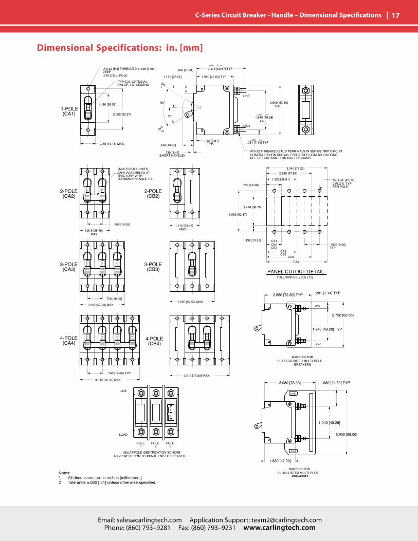
| 17 C-Series Circuit Breaker - Handle – Dimensional Specifications
Notes: 1 All dimensions are in inches [millimeters].2 Tolerance±.020[.51]unlessotherwisespecified.
Dimensional Specifications: in. [mm]

Email: [email protected] Application Support: [email protected] Phone: (860) 793–9281 Fax: (860) 793–9231 www.carlingtech.com
18 | C-Series Circuit Breaker - Handleguard – Dimensional Specifications
Notes: 1 All dimensions are in inches [millimeters].2 Tolerance±.020[.51]unlessotherwisespecified.
Dimensional Specifications: in. [mm]

Email: [email protected] Application Support: [email protected] Phone: (860) 793–9281 Fax: (860) 793–9231 www.carlingtech.com
Email: [email protected] Application Support: [email protected] Phone: (860) 793–9281 Fax: (860) 793–9231 www.carlingtech.com
| 19 C-Series Circuit Breaker - Arc Chute Barrier UL Recognized/Listed – Dimensional Specifications
Notes: 1 Only1-poleand3-poleconfigurationsshown.Arcchute(withoutbarrier)andarcchute barrier also available for 2-pole construction.2 Dimensions apply to all variations shown.3 Notice that line and load terminal orientation for indicate on and indicate off rocker circuit breakers are opposite.4 Screw type terminals shown for Rocker style (CF1, C11, etc) circuit breakers. For otherterminalconfigurationsseecircuitandterminaldiagrams.5 All dimensions are in inches [millimeters].6 Tolerance±.020unlessotherwisespecified.7 Must be ordered under a special catalog number.
Dimensional Specifications: in. [mm]

Email: [email protected] Application Support: [email protected] Phone: (860) 793–9281 Fax: (860) 793–9231 www.carlingtech.com
20 | C-Series Circuit Breaker - Parallel Pole – Dimensional Specifications
Notes: 1 All dimensions are in inches [millimeters].2 Tolerance±.020[.51]unlessotherwisespecified.
Dimensional Specifications: in. [mm]
Email: [email protected] Application Support: [email protected] Phone: (860) 793–9281 Fax: (860) 793–9231 www.carlingtech.com
Email: [email protected] Application Support: [email protected] Phone: (860) 793–9281 Fax: (860) 793–9231 www.carlingtech.com
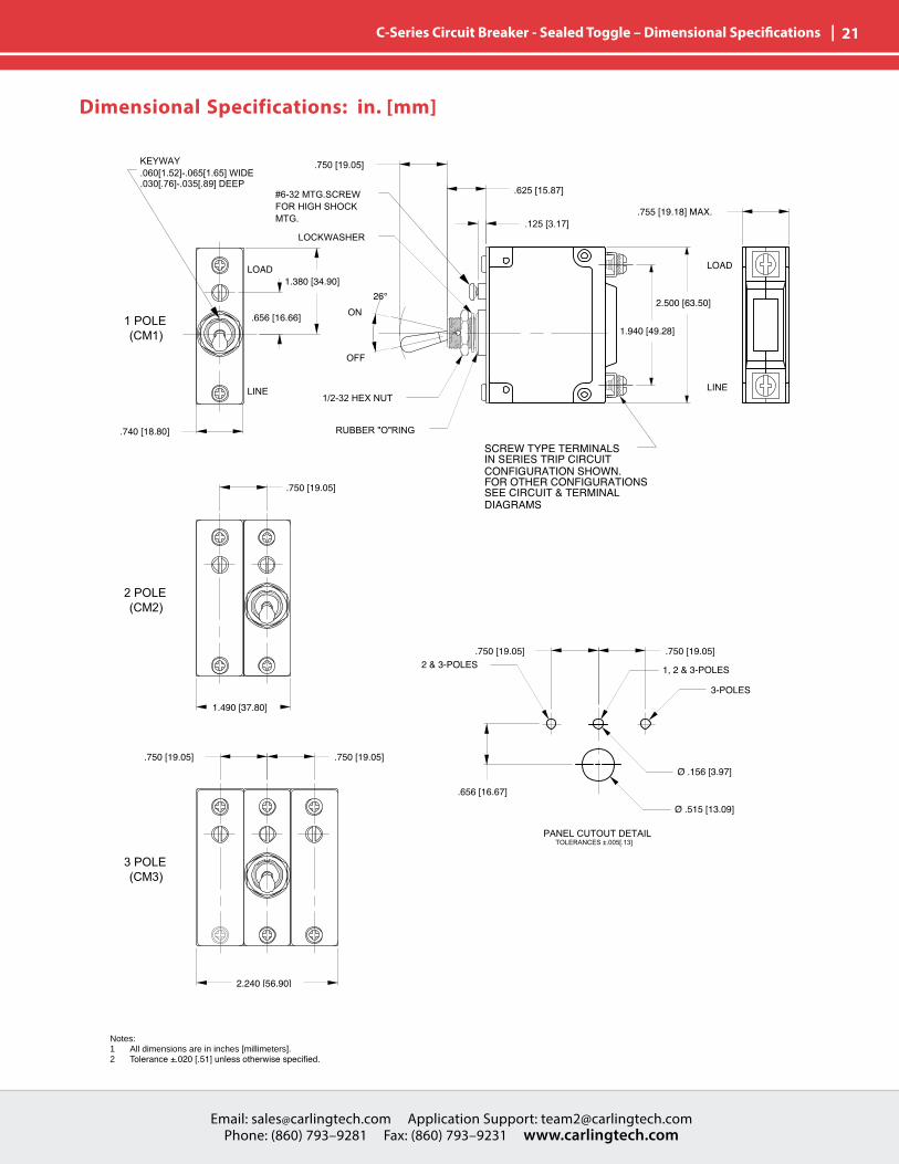
| 21 C-Series Circuit Breaker - Sealed Toggle – Dimensional Specifications
Notes: 1 All dimensions are in inches [millimeters].2 Tolerance±.020[.51]unlessotherwisespecified.
Dimensional Specifications: in. [mm]

Email: [email protected] Application Support: [email protected] Phone: (860) 793–9281 Fax: (860) 793–9231 www.carlingtech.com
22 | C-Series Circuit Breaker - Rocker – Circuit & Terminal Diagrams
Notes: 1 All dimensions are in inches [millimeters].2 Tolerance±.020[.51]unlessotherwisespecified.3 Schematic shown represents current trip circuit.
Circuit & Terminal Diagrams: in. [mm]

Email: [email protected] Application Support: [email protected] Phone: (860) 793–9281 Fax: (860) 793–9231 www.carlingtech.com
Email: [email protected] Application Support: [email protected] Phone: (860) 793–9281 Fax: (860) 793–9231 www.carlingtech.com
| 23 C-Series Circuit Breaker - Rocker – Dimensional Specifications
Notes: 1 Dimensions apply to all variations shown. Notice that circuit breaker line and load terminal orientation on indicate OFF is opposite of indicate ON.2 For pole orientation with horizontal legend, rotate front view clockwise 90°.3 All dimensions are in inches [millimeters].4 Tolerance±.020[.51]unlessotherwisespecified.
Dimensional Specifications: in. [mm]
Email: [email protected] Application Support: [email protected] Phone: (860) 793–9281 Fax: (860) 793–9231 www.carlingtech.com
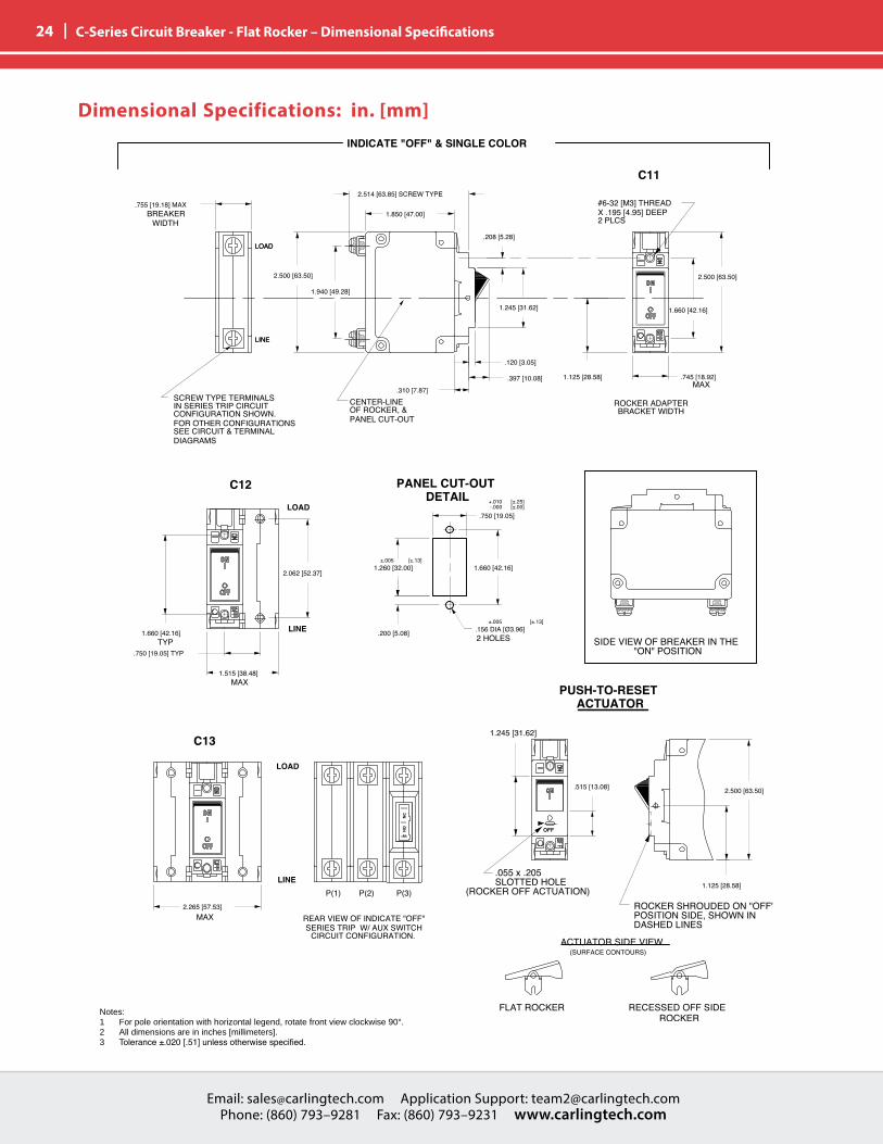
24 | C-Series Circuit Breaker - Flat Rocker – Dimensional Specifications
Notes: 1 For pole orientation with horizontal legend, rotate front view clockwise 90°.2 All dimensions are in inches [millimeters].3 Tolerance±.020[.51]unlessotherwisespecified.
Dimensional Specifications: in. [mm]

Email: [email protected] Application Support: [email protected] Phone: (860) 793–9281 Fax: (860) 793–9231 www.carlingtech.com
Email: [email protected] Application Support: [email protected] Phone: (860) 793–9281 Fax: (860) 793–9231 www.carlingtech.com
| 25 Reps & Contact
TEMCO NorthwestHanna Lind Ltd.
SierraLD. Allen Norris
PacentTSI North
TSI
DM AssocEastDy-tronix Inc.
Sunbelt ComponentsPinnacle Marketing
Omega LimitedBridge Marketing
Alaska, H
awaii
MateraW. Canada
LuscombeEngineering
SignalEnterprises
MateraE. Canada
DMMichigan
DM MexicoMexico
MatrixSouth America
DMAssoc
MelodyEmery
ProRepSolutions
Authorized Sales Representatives
About Carling
Founded in 1920, Carling Technologies is a leading manufacturer of electrical and electronic switches and assemblies, circuit breakers, electronic controls, power distribution units, and multiplexed power distribution systems. With four ISO registered manufacturing facilities and technical sales offices worldwide, Carling Technologies Sales, Service and Engineering teams do much more than manufacture electrical components, they engineer powerful solutions! To learn more about Carling please visit www.carlingtech.com/company-profile.
To view all of Carling’s environmental, quality, health & safety certifications please visit www.carlingtech.com/environmental-certifications
Click on the group name on the map below to find your local representative or visit www.carlingtech.com/findarep.
AmericasEuropeMiddle EastAfrica
Asia-PacificOceania
«
«
«««
MIDWEST
NORTHERN
SOUTHEAST
LATIN AMERICA
WEST

Worldwide HeadquartersCarling Technologies, Inc.60 Johnson Avenue, Plainville, CT 06062Phone: 860.793.9281 Fax: 860.793.9231Email: [email protected]
Northern Region Sales Office: [email protected] Region Sales Office: [email protected] Region Sales Office: [email protected] Region Sales Office: [email protected] America Sales Office: [email protected]
Asia-Pacific HeadquartersCarling Technologies, Asia-Pacific Ltd.,Kowloon, Hong KongPhone: Int + 852-2737-2277 Fax: Int + 852-2736-9332Email: [email protected]
Shenzhen, China: [email protected], China: [email protected], India: [email protected], Taiwan: [email protected], Japan: [email protected]
Europe | Middle East | Africa HeadquartersCarling Technologies LTD4 Airport Business Park, Exeter Airport, Clyst Honiton, Exeter, Devon, EX5 2UL, UKPhone: Int + 44 1392.364422 Fax: Int + 44 1392.364477Email: [email protected]
Germany: [email protected]: [email protected]
www.carlingtech.com REV_07_2016