c-more hardware user manual - automationdirect · 2–2 ea-user-m hardware user manual, ......
TRANSCRIPT
speCifiCaTions 222ChapterChapterChapter
In This Chapter...Available Models ........................................................................................................2–2
Model Specifications .................................................................................................2–36” Base Feature Models . . . . . . . . . . . . . . . . . . . . . . . . . . . . . . . . . . . . . . . . . . . . . . . . . . . . . . . . . . . . . . . . . . . . . . . . . . . . . . . . . . . . . . . . . . . .2–46” Full Feature Models . . . . . . . . . . . . . . . . . . . . . . . . . . . . . . . . . . . . . . . . . . . . . . . . . . . . . . . . . . . . . . . . . . . . . . . . . . . . . . . . . . . . . . . . . . . . .2–56” Obsolete Models . . . . . . . . . . . . . . . . . . . . . . . . . . . . . . . . . . . . . . . . . . . . . . . . . . . . . . . . . . . . . . . . . . . . . . . . . . . . . . . . . . . . . . . . . . . . . . . . .2–68” and 10” Full Feature Models . . . . . . . . . . . . . . . . . . . . . . . . . . . . . . . . . . . . . . . . . . . . . . . . . . . . . . . . . . . . . . . . . . . . . . . . . . . . . . .2–812” and 15” Full Feature Models . . . . . . . . . . . . . . . . . . . . . . . . . . . . . . . . . . . . . . . . . . . . . . . . . . . . . . . . . . . . . . . . . . . . . . . . . . . . .2–9
EA7-S6M-R, S6C-R, T6CL-R, S6M, S6C, T6C, T6CL (Dimensions and Ports & Memory Exp.) ................................................................2–10
EA7-T8C (Dimensions and Ports & Memory Exp.) .................................................2–12
EA7-T10C (Dimensions and Ports & Memory Exp.) ...............................................2–14
EA7-T12C (Dimensions and Ports & Memory Exp.) ...............................................2–16
EA7-T15C (Dimensions and Ports & Memory Exp.) ...............................................2–18
Mounting Clearances ..............................................................................................2–20
Communications Ports ............................................................................................2–21
Audio WAV File Specifications.................................................................................2–23
Memory Organization .............................................................................................2–24
Handling External Memory Devices ........................................................................2–25
Power Loss Detection and Power Retention Period ..............................................2–26
Data Logging Function and Logging Media ..........................................................2–26
Data Logging - Memory Device Full .......................................................................2–26
Chemical Compatibility ...........................................................................................2–27
EA-USER-M Hardware User Manual, 2nd Ed. Rev. H, 05/182-2
Chapter 2: Specifications
1
2
3
4
5
6
7
8
9
10
11
12
13
14
A
B
C
D
®
1
2
3
4
5
6
7
8
9
10
11
12
13
14
a
b
C
d
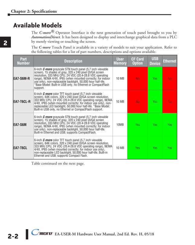
Available ModelsThe C-more® Operator Interface is the next generation of touch panel brought to you by AutomationDirect. It has been designed to display and interchange graphical data from a PLC by merely viewing or touching the screen.
The C-more Touch Panel is available in a variety of models to suit your application. Refer to the following tables for a list of part numbers, descriptions and options available.
Table continued on the next page.
Part Number Description User
MemoryCF Card Option
USB Device Ethernet
EA7-S6M-R
6-inch C-more grayscale STN touch panel (5.7 inch viewable screen), 15 shades of gray, 320 x 240 pixel QVGA screen resolution, 333 MHz CPU, 24 VDC (20.4-28.8 VDC operating range), NEMA 4/4X, IP65 (when mounted correctly; for indoor use only), non-replaceable backlight, 50,000 hour half-life. *Base Model: Built-in USB only, no Ethernet or CompactFlash support.
10 MB No Yes No
EA7-T6CL-R
6-inch C-more color TFT touch panel (5.7 inch viewable screen), 64K colors, 320 x 240 pixel QVGA screen resolution, 333 MHz CPU, 24 VDC (20.4-28.8 VDC operating range), NEMA 4/4X, IP65 (when mounted correctly; for indoor use only), non-replaceable LED backlight, 50,000 hour half-life. *Base Model: Built-in USB only, no Ethernet or CompactFlash support.
10 MB No Yes No
EA7-S6M
6-inch C-more grayscale STN touch panel (5.7 inch viewable screen), 15 shades of gray, 320 x 240 pixel QVGA screen resolution, 333 MHz CPU, 24 VDC (20.4-28.8 VDC operating range), NEMA 4/4X, IP65 (when mounted correctly; for indoor use only), non-replaceable backlight, 50,000 hour half-life. Built-in Ethernet and USB; supports CompactFlash.
10MB Yes Yes Yes
EA7-T6CL
6-inch C-more color TFT touch panel (5.7 inch viewable screen), 64K colors, 320 x 240 pixel QVGA screen resolution, 333 MHz CPU, 24 VDC (20.4-28.8 VDC operating range), NEMA 4/4X, IP65 (when mounted correctly; for indoor use only), non-replaceable LED backlight, 50,000 hour half-life. Built-in Ethernet and USB; supports Compact Flash.
10 MB Yes Yes Yes
EA-USER-M Hardware User Manual, 2nd Ed. Rev. H, 05/18 2-3
Chapter 2: Specifications
1
2
3
4
5
6
7
8
9
10
11
12
13
14
A
B
C
D
®
1
2
3
4
5
6
7
8
9
10
11
12
13
14
a
b
C
d
Available Models (cont’d)Part
Number Description User Memory
CF Card Option
USB Device Ethernet
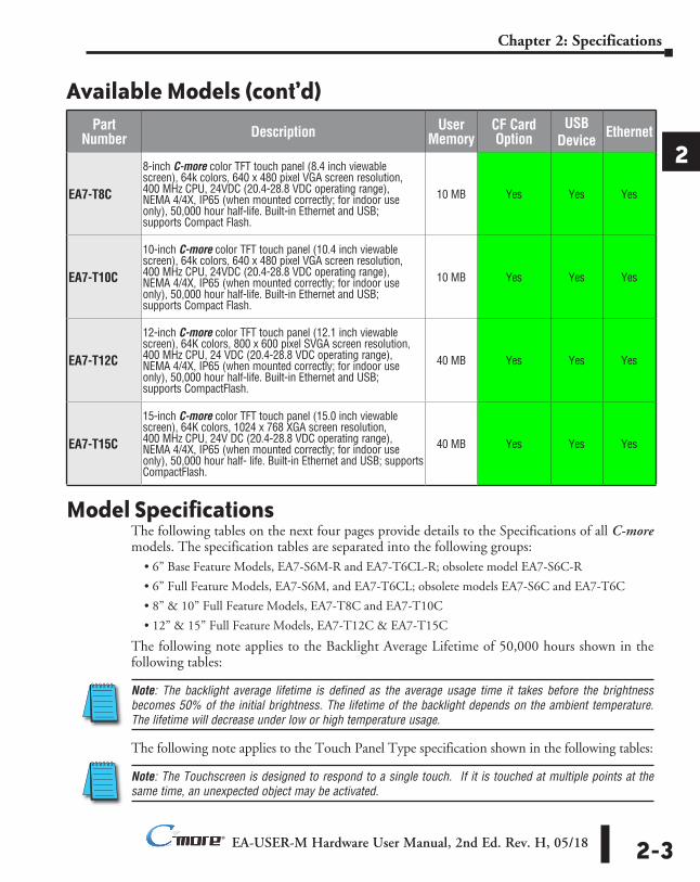
EA7-T8C
8-inch C-more color TFT touch panel (8.4 inch viewable screen), 64k colors, 640 x 480 pixel VGA screen resolution, 400 MHz CPU, 24VDC (20.4-28.8 VDC operating range), NEMA 4/4X, IP65 (when mounted correctly; for indoor use only), 50,000 hour half-life. Built-in Ethernet and USB; supports Compact Flash.
10 MB Yes Yes Yes
EA7-T10C
10-inch C-more color TFT touch panel (10.4 inch viewable screen), 64k colors, 640 x 480 pixel VGA screen resolution, 400 MHz CPU, 24VDC (20.4-28.8 VDC operating range), NEMA 4/4X, IP65 (when mounted correctly; for indoor use only), 50,000 hour half-life. Built-in Ethernet and USB; supports Compact Flash.
10 MB Yes Yes Yes
EA7-T12C
12-inch C-more color TFT touch panel (12.1 inch viewable screen), 64K colors, 800 x 600 pixel SVGA screen resolution, 400 MHz CPU, 24 VDC (20.4-28.8 VDC operating range), NEMA 4/4X, IP65 (when mounted correctly; for indoor use only), 50,000 hour half-life. Built-in Ethernet and USB; supports CompactFlash.
40 MB Yes Yes Yes
EA7-T15C
15-inch C-more color TFT touch panel (15.0 inch viewable screen), 64K colors, 1024 x 768 XGA screen resolution, 400 MHz CPU, 24V DC (20.4-28.8 VDC operating range), NEMA 4/4X, IP65 (when mounted correctly; for indoor use only), 50,000 hour half- life. Built-in Ethernet and USB; supports CompactFlash.
40 MB Yes Yes Yes
Model SpecificationsThe following tables on the next four pages provide details to the Specifications of all C-more models. The specification tables are separated into the following groups:
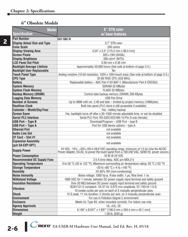
• 6” Base Feature Models, EA7-S6M-R and EA7-T6CL-R; obsolete model EA7-S6C-R
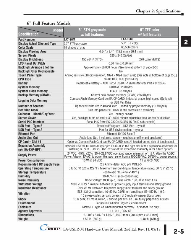
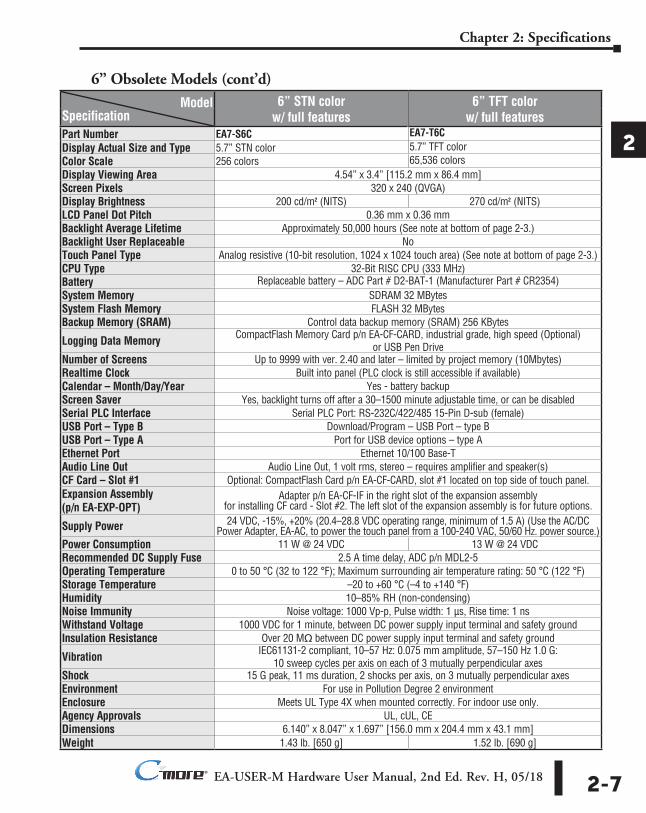
• 6” Full Feature Models, EA7-S6M, and EA7-T6CL; obsolete models EA7-S6C and EA7-T6C
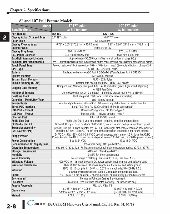
• 8” & 10” Full Feature Models, EA7-T8C and EA7-T10C
• 12” & 15” Full Feature Models, EA7-T12C & EA7-T15C
The following note applies to the Backlight Average Lifetime of 50,000 hours shown in the following tables:
Note: The backlight average lifetime is defined as the average usage time it takes before the brightness becomes 50% of the initial brightness. The lifetime of the backlight depends on the ambient temperature. The lifetime will decrease under low or high temperature usage.
The following note applies to the Touch Panel Type specification shown in the following tables:
Note: The Touchscreen is designed to respond to a single touch. If it is touched at multiple points at the same time, an unexpected object may be activated.
EA-USER-M Hardware User Manual, 2nd Ed. Rev. H, 05/182-4
Chapter 2: Specifications
1
2
3
4
5
6
7
8
9
10
11
12
13
14
A
B
C
D
®
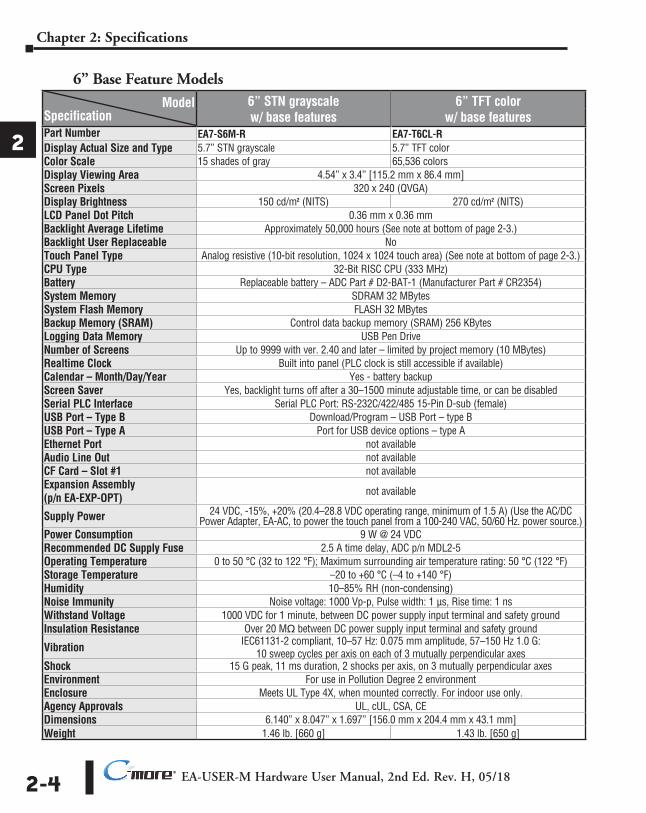
6” Base Feature Models
1
2
3
4
5
6
7
8
9
10
11
12
13
14
a
b
C
d
Model 6” STN grayscale w/ base features
6” TFT color w/ base featuresSpecification
Part Number EA7-S6M-R EA7-T6CL-RDisplay Actual Size and Type 5.7” STN grayscale 5.7” TFT colorColor Scale 15 shades of gray 65,536 colorsDisplay Viewing Area 4.54” x 3.4” [115.2 mm x 86.4 mm]Screen Pixels 320 x 240 (QVGA)Display Brightness 150 cd/m2 (NITS) 270 cd/m2 (NITS)LCD Panel Dot Pitch 0.36 mm x 0.36 mmBacklight Average Lifetime Approximately 50,000 hours (See note at bottom of page 2-3.)Backlight User Replaceable NoTouch Panel Type Analog resistive (10-bit resolution, 1024 x 1024 touch area) (See note at bottom of page 2-3.)CPU Type 32-Bit RISC CPU (333 MHz)Battery Replaceable battery – ADC Part # D2-BAT-1 (Manufacturer Part # CR2354)System Memory SDRAM 32 MBytesSystem Flash Memory FLASH 32 MBytesBackup Memory (SRAM) Control data backup memory (SRAM) 256 KBytesLogging Data Memory USB Pen DriveNumber of Screens Up to 9999 with ver. 2.40 and later – limited by project memory (10 MBytes)Realtime Clock Built into panel (PLC clock is still accessible if available)Calendar – Month/Day/Year Yes - battery backupScreen Saver Yes, backlight turns off after a 30–1500 minute adjustable time, or can be disabledSerial PLC Interface Serial PLC Port: RS-232C/422/485 15-Pin D-sub (female)USB Port – Type B Download/Program – USB Port – type BUSB Port – Type A Port for USB device options – type AEthernet Port not availableAudio Line Out not availableCF Card – Slot #1 not availableExpansion Assembly (p/n EA-EXP-OPT)
not available
Supply Power 24 VDC, -15%, +20% (20.4–28.8 VDC operating range, minimum of 1.5 A) (Use the AC/DC Power Adapter, EA-AC, to power the touch panel from a 100-240 VAC, 50/60 Hz. power source.)
Power Consumption 9 W @ 24 VDCRecommended DC Supply Fuse 2.5 A time delay, ADC p/n MDL2-5Operating Temperature 0 to 50 °C (32 to 122 °F); Maximum surrounding air temperature rating: 50 °C (122 °F)Storage Temperature –20 to +60 °C (–4 to +140 °F)Humidity 10–85% RH (non-condensing)Noise Immunity Noise voltage: 1000 Vp-p, Pulse width: 1 µs, Rise time: 1 nsWithstand Voltage 1000 VDC for 1 minute, between DC power supply input terminal and safety groundInsulation Resistance Over 20 Mq between DC power supply input terminal and safety ground
Vibration IEC61131-2 compliant, 10–57 Hz: 0.075 mm amplitude, 57–150 Hz 1.0 G: 10 sweep cycles per axis on each of 3 mutually perpendicular axes
Shock 15 G peak, 11 ms duration, 2 shocks per axis, on 3 mutually perpendicular axesEnvironment For use in Pollution Degree 2 environmentEnclosure Meets UL Type 4X, when mounted correctly. For indoor use only.Agency Approvals UL, cUL, CSA, CEDimensions 6.140” x 8.047” x 1.697” [156.0 mm x 204.4 mm x 43.1 mm]Weight 1.46 lb. [660 g] 1.43 lb. [650 g]
EA-USER-M Hardware User Manual, 2nd Ed. Rev. H, 05/18 2-5
Chapter 2: Specifications
1
2
3
4
5
6
7
8
9
10
11
12
13
14
A
B
C
D
®
6” Full Feature Models
1
2
3
4
5
6
7
8
9
10
11
12
13
14
a
b
C
d
Model 6” STN grayscale w/ full features
6” TFT color w/ full featuresSpecification
Part Number EA7-S6M EA7-T6CLDisplay Actual Size and Type 5.7” STN grayscale 5.7” TFT colorColor Scale 15 shades of gray 65,536 colorsDisplay Viewing Area 4.54” x 3.4” [115.2 mm x 86.4 mm]Screen Pixels 320 x 240 (QVGA)Display Brightness 150 cd/m2 (NITS) 270 cd/m2 (NITS)LCD Panel Dot Pitch 0.36 mm x 0.36 mmBacklight Average Lifetime Approximately 50,000 hours (See note at bottom of page 2-3.)Backlight User Replaceable NoTouch Panel Type Analog resistive (10-bit resolution, 1024 x 1024 touch area) (See note at bottom of page 2-3.)CPU Type 32-Bit RISC CPU (333 MHz)Battery Replaceable battery – ADC Part # D2-BAT-1 (Manufacturer Part # CR2354)System Memory SDRAM 32 MBytesSystem Flash Memory FLASH 32 MBytesBackup Memory (SRAM) Control data backup memory (SRAM) 256 KBytes
Logging Data Memory CompactFlash Memory Card p/n EA-CF-CARD, industrial grade, high speed (Optional) or USB Pen Drive
Number of Screens Up to 9999 with ver. 2.40 and later – limited by project memory (10 MBytes)Realtime Clock Built into panel (PLC clock is still accessible if available)Calendar – Month/Day/Year Yes - battery backupScreen Saver Yes, backlight turns off after a 30–1500 minute adjustable time, or can be disabledSerial PLC Interface Serial PLC Port: RS-232C/422/485 15-Pin D-sub (female)USB Port – Type B Download/Program – USB Port – type BUSB Port – Type A Port for USB device options – type AEthernet Port Ethernet 10/100 Base-TAudio Line Out Audio Line Out, 1 volt rms, stereo – requires amplifier and speaker(s)CF Card – Slot #1 Optional: CompactFlash Card p/n EA-CF-CARD, slot #1 located on top side of touch panel.Expansion Assembly (p/n EA-EXP-OPT)
Optional: Use the CF Card Adapter p/n EA-CF-IF in the right slot of the expansion assembly for installing CF card - Slot #2. The left slot of the expansion assembly is for future options.
Supply Power 24 VDC, -15%, +20% (20.4–28.8 VDC operating range, minimum of 1.5 A) (Use the AC/DC Power Adapter, EA-AC, to power the touch panel from a 100-240 VAC, 50/60 Hz. power source.)
Power Consumption 10 W @ 24 VDC 11 W @ 24 VDCRecommended DC Supply Fuse 2.5 A time delay, ADC p/n MDL2-5Operating Temperature 0 to 50 °C (32 to 122 °F); Maximum surrounding air temperature rating: 50 °C (122 °F)Storage Temperature –20 to +60 °C (–4 to +140 °F)Humidity 10–85% RH (non-condensing)Noise Immunity Noise voltage: 1000 Vp-p, Pulse width: 1 µs, Rise time: 1 nsWithstand Voltage 1000 VDC for 1 minute, between DC power supply input terminal and safety groundInsulation Resistance Over 20 Mq between DC power supply input terminal and safety ground
Vibration IEC61131-2 compliant, 10–57 Hz: 0.075 mm amplitude, 57–150 Hz 1.0 G: 10 sweep cycles per axis on each of 3 mutually perpendicular axes
Shock 15 G peak, 11 ms duration, 2 shocks per axis, on 3 mutually perpendicular axesEnvironment For use in Pollution Degree 2 environmentEnclosure Meets UL Type 4X when mounted correctly. For indoor use only.Agency Approvals UL, cUL, CSA, CEDimensions 6.140” x 8.047” x 1.697” [156.0 mm x 204.4 mm x 43.1 mm]Weight 1.50 lb. [680 g] 1.48 lb. [670 g]
EA-USER-M Hardware User Manual, 2nd Ed. Rev. H, 05/182-6
Chapter 2: Specifications
1
2
3
4
5
6
7
8
9
10
11
12
13
14
A
B
C
D
®
6” Obsolete Models
1
2
3
4
5
6
7
8
9
10
11
12
13
14
a
b
C
d
Model 6” STN color w/ base featuresSpecification
Part Number EA7-S6C-RDisplay Actual Size and Type 5.7” STN colorColor Scale 256 colorsDisplay Viewing Area 4.54” x 3.4” [115.2 mm x 86.4 mm]Screen Pixels 320 x 240 (QVGA)Display Brightness 200 cd/m2 (NITS)LCD Panel Dot Pitch 0.36 mm x 0.36 mmBacklight Average Lifetime Approximately 50,000 hours (See note at bottom of page 2-3.)Backlight User Replaceable NoTouch Panel Type Analog resistive (10-bit resolution, 1024 x 1024 touch area) (See note at bottom of page 2-3.)CPU Type 32-Bit RISC CPU (333 MHz)Battery Replaceable battery – ADC Part # D2-BAT-1 (Manufacturer Part # CR2354)System Memory SDRAM 32 MBytesSystem Flash Memory FLASH 32 MBytesBackup Memory (SRAM) Control data backup memory (SRAM) 256 KBytesLogging Data Memory USB Pen DriveNumber of Screens Up to 9999 with ver. 2.40 and later – limited by project memory (10Mbytes)Realtime Clock Built into panel (PLC clock is still accessible if available)Calendar – Month/Day/Year Yes - battery backupScreen Saver Yes, backlight turns off after a 30–1500 minute adjustable time, or can be disabledSerial PLC Interface Serial PLC Port: RS-232C/422/485 15-Pin D-sub (female)USB Port – Type B Download/Program – USB Port – type BUSB Port – Type A Port for USB device options – type AEthernet Port not availableAudio Line Out not availableCF Card – Slot #1 not availableExpansion Assembly (p/n EA-EXP-OPT)
not available
Supply Power 24 VDC, -15%, +20% (20.4–28.8 VDC operating range, minimum of 1.5 A) (Use the AC/DC Power Adapter, EA-AC, to power the touch panel from a 100-240 VAC, 50/60 Hz. power source.)
Power Consumption 10 W @ 24 VDCRecommended DC Supply Fuse 2.5 A time delay, ADC p/n MDL2-5Operating Temperature 0 to 50 °C (32 to 122 °F); Maximum surrounding air temperature rating: 50 °C (122 °F)Storage Temperature –20 to +60 °C (–4 to +140 °F)Humidity 10–85% RH (non-condensing)Noise Immunity Noise voltage: 1000 Vp-p, Pulse width: 1 µs, Rise time: 1 nsWithstand Voltage 1000 VDC for 1 minute, between DC power supply input terminal and safety groundInsulation Resistance Over 20 Mq between DC power supply input terminal and safety ground
Vibration IEC61131-2 compliant, 10–57 Hz: 0.075 mm amplitude, 57–150 Hz 1.0 G: 10 sweep cycles per axis on each of 3 mutually perpendicular axes
Shock 15 G peak, 11 ms duration, 2 shocks per axis, on 3 mutually perpendicular axesEnvironment For use in Pollution Degree 2 environmentEnclosure Meets UL Type 4X, when mounted correctly. For indoor use only.Agency Approvals UL, cUL, CEDimensions 6.140” x 8.047” x 1.697” [156.0 mm x 204.4 mm x 43.1 mm]Weight 1.39 lb. [630 g]
EA-USER-M Hardware User Manual, 2nd Ed. Rev. H, 05/18 2-7
Chapter 2: Specifications
1
2
3
4
5
6
7
8
9
10
11
12
13
14
A
B
C
D
®
6” Obsolete Models (cont’d)
1
2
3
4
5
6
7
8
9
10
11
12
13
14
a
b
C
d
Model 6” STN color w/ full features
6” TFT color w/ full featuresSpecification
Part Number EA7-S6C EA7-T6CDisplay Actual Size and Type 5.7” STN color 5.7” TFT colorColor Scale 256 colors 65,536 colorsDisplay Viewing Area 4.54” x 3.4” [115.2 mm x 86.4 mm]Screen Pixels 320 x 240 (QVGA)Display Brightness 200 cd/m2 (NITS) 270 cd/m2 (NITS)LCD Panel Dot Pitch 0.36 mm x 0.36 mmBacklight Average Lifetime Approximately 50,000 hours (See note at bottom of page 2-3.)Backlight User Replaceable NoTouch Panel Type Analog resistive (10-bit resolution, 1024 x 1024 touch area) (See note at bottom of page 2-3.)CPU Type 32-Bit RISC CPU (333 MHz)Battery Replaceable battery – ADC Part # D2-BAT-1 (Manufacturer Part # CR2354)System Memory SDRAM 32 MBytesSystem Flash Memory FLASH 32 MBytesBackup Memory (SRAM) Control data backup memory (SRAM) 256 KBytes
Logging Data Memory CompactFlash Memory Card p/n EA-CF-CARD, industrial grade, high speed (Optional) or USB Pen Drive
Number of Screens Up to 9999 with ver. 2.40 and later – limited by project memory (10Mbytes)Realtime Clock Built into panel (PLC clock is still accessible if available)Calendar – Month/Day/Year Yes - battery backupScreen Saver Yes, backlight turns off after a 30–1500 minute adjustable time, or can be disabledSerial PLC Interface Serial PLC Port: RS-232C/422/485 15-Pin D-sub (female)USB Port – Type B Download/Program – USB Port – type BUSB Port – Type A Port for USB device options – type AEthernet Port Ethernet 10/100 Base-TAudio Line Out Audio Line Out, 1 volt rms, stereo – requires amplifier and speaker(s)CF Card – Slot #1 Optional: CompactFlash Card p/n EA-CF-CARD, slot #1 located on top side of touch panel.Expansion Assembly (p/n EA-EXP-OPT)
Adapter p/n EA-CF-IF in the right slot of the expansion assembly for installing CF card - Slot #2. The left slot of the expansion assembly is for future options.
Supply Power 24 VDC, -15%, +20% (20.4–28.8 VDC operating range, minimum of 1.5 A) (Use the AC/DC Power Adapter, EA-AC, to power the touch panel from a 100-240 VAC, 50/60 Hz. power source.)
Power Consumption 11 W @ 24 VDC 13 W @ 24 VDCRecommended DC Supply Fuse 2.5 A time delay, ADC p/n MDL2-5Operating Temperature 0 to 50 °C (32 to 122 °F); Maximum surrounding air temperature rating: 50 °C (122 °F)Storage Temperature –20 to +60 °C (–4 to +140 °F)Humidity 10–85% RH (non-condensing)Noise Immunity Noise voltage: 1000 Vp-p, Pulse width: 1 µs, Rise time: 1 nsWithstand Voltage 1000 VDC for 1 minute, between DC power supply input terminal and safety groundInsulation Resistance Over 20 Mq between DC power supply input terminal and safety ground
Vibration IEC61131-2 compliant, 10–57 Hz: 0.075 mm amplitude, 57–150 Hz 1.0 G: 10 sweep cycles per axis on each of 3 mutually perpendicular axes
Shock 15 G peak, 11 ms duration, 2 shocks per axis, on 3 mutually perpendicular axesEnvironment For use in Pollution Degree 2 environmentEnclosure Meets UL Type 4X when mounted correctly. For indoor use only.Agency Approvals UL, cUL, CEDimensions 6.140” x 8.047” x 1.697” [156.0 mm x 204.4 mm x 43.1 mm]Weight 1.43 lb. [650 g] 1.52 lb. [690 g]
EA-USER-M Hardware User Manual, 2nd Ed. Rev. H, 05/182-8
Chapter 2: Specifications
1
2
3
4
5
6
7
8
9
10
11
12
13
14
A
B
C
D
®
8” and 10” Full Feature Models
1
2
3
4
5
6
7
8
9
10
11
12
13
14
a
b
C
d
Model 8” TFT color w/ full features
10” TFT color w/ full featuresSpecifications
Part Number EA7-T8C EA7-T10CDisplay Actual Size and Type 8.4” TFT color 10.4” TFT colorColor Scale 65,536 colorsDisplay Viewing Area 6.73” x 5.05” [170.9 mm x 128.2 mm] 8.31” x 6.24” [211.2 mm x 158.4 mm]Screen Pixels 640 x 480 (VGA)Display Brightness 300 cd/m2 (NITS) 270 cd/m2 (NITS)LCD Panel Dot Pitch 0.267 mm x 0.267 mm 0.33 mm x 0.33 mmBacklight Average Lifetime Approximately 50,000 hours (See note at bottom of page 2-3.)Backlight User Replaceable Yes – Correct replacement bulb is dependent on the panel serial no, see Chapter 9 for complete details.Touch Panel Type Analog resistive (10-bit resolution, 1024 x 1024 touch area) (See note at bottom of page 2-3.)CPU Type 32-Bit RISC CPU (400 MHz)Battery Replaceable battery – ADC Part # D2-BAT-1 (Manufacturer Part # CR2354)System Memory SDRAM 32 MBytesSystem Flash Memory FLASH 32 MBytesBackup Memory (SRAM) Control data backup memory (SRAM) 256 KBytes
Logging Data Memory CompactFlash Memory Card p/n EA-CF-CARD, industrial grade, high speed (Optional) or USB Pen Drive
Number of Screens Up to 9999 with ver. 2.40 and later – limited by project memory (10 MBytes)Realtime Clock Built into panel (PLC clock is still accessible if available)Calendar – Month/Day/Year Yes - battery backupScreen Saver Yes, backlight turns off after a 30–1500 minute adjustable time, or can be disabledSerial PLC Interface Serial PLC Port: RS-232C/422/485 15-Pin D-sub (female)USB Port – Type B Download/Program – USB Port – type BUSB Port – Type A Port for USB 1.1 device options – type AEthernet Port Ethernet 10/100 Base-TAudio Line Out Audio Line Out, 1 volt rms, stereo – requires amplifier and speaker(s)CF Card – Slot #1 Optional: CompactFlash Card p/n EA-CF-CARD, slot #1 located on top side of touch panel.Expansion Assembly (p/n EA-EXP-OPT)
Optional: Use the CF Card Adapter p/n EA-CF-IF in the right slot of the expansion assembly for installing CF card - Slot #2. The left slot of the expansion assembly is for future options.
Supply Power 24 VDC, -15%, +20% (20.4–28.8 VDC operating range, minimum of 1.5 A) (Use the AC/DC Power Adapter, EA-AC, to power the touch panel from a 100-240 VAC, 50/60 Hz. power source.)
Power Consumption 15 W @ 24 VDC 17 W @ 24 VDCRecommended DC Supply Fuse 2.5 A time delay, ADC p/n MDL2-5Operating Temperature 0 to 50 °C (32 to 122 °F); Maximum surrounding air temperature rating: 50 °C (122 °F)Storage Temperature –20 to +60 °C (–4 to +140 °F)Humidity 10–85% RH (non-condensing)Noise Immunity Noise voltage: 1000 Vp-p, Pulse width: 1 µs, Rise time: 1 nsWithstand Voltage 1000 VDC for 1 minute, between DC power supply input terminal and safety groundInsulation Resistance Over 20 Mq between DC power supply input terminal and safety ground
Vibration IEC61131-2 compliant, 10–57 Hz: 0.075 mm amplitude, 57–150 Hz 1.0 G: 10 sweep cycles per axis on each of 3 mutually perpendicular axes
Shock 15 G peak, 11 ms duration, 2 shocks per axis, on 3 mutually perpendicular axesEnvironment For use in Pollution Degree 2 environmentEnclosure Meets UL Type 4X when mounted correctly. For indoor use only.Agency Approvals UL, cUL, CSA, CE
Dimensions 8.748” x 10.894” x 2.053” [222.2 mm x 276.7 mm x 52.1 mm]
10.669” x 13.661” x 2.079” [271.0 x 347.0 x 52.8 mm]
Weight 2.60 lb. [1,180 g] 3.55 lb. [1,610 g]
EA-USER-M Hardware User Manual, 2nd Ed. Rev. H, 05/18 2-9
Chapter 2: Specifications
1
2
3
4
5
6
7
8
9
10
11
12
13
14
A
B
C
D
®
12” and 15” Full Feature Models
1
2
3
4
5
6
7
8
9
10
11
12
13
14
a
b
C
d
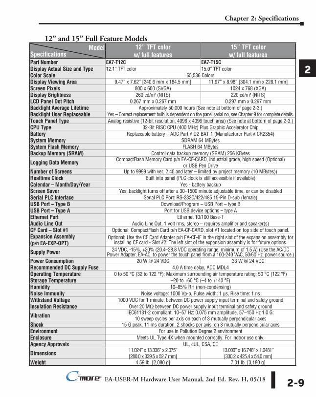
Model 12” TFT color w/ full features
15” TFT color w/ full featuresSpecifications
Part Number EA7-T12C EA7-T15CDisplay Actual Size and Type 12.1” TFT color 15.0” TFT colorColor Scale 65,536 ColorsDisplay Viewing Area 9.47” x 7.62” [240.6 mm x 184.5 mm] 11.97” x 8.98” [304.1 mm x 228.1 mm]Screen Pixels 800 x 600 (SVGA) 1024 x 768 (XGA)Display Brightness 260 cd/m2 (NITS) 220 cd/m2 (NITS)LCD Panel Dot Pitch 0.267 mm x 0.267 mm 0.297 mm x 0.297 mmBacklight Average Lifetime Approximately 50,000 hours (See note at bottom of page 2-3.)Backlight User Replaceable Yes – Correct replacement bulb is dependent on the panel serial no, see Chapter 9 for complete details.Touch Panel Type Analog resistive (12-bit resolution, 4096 x 4096 touch area) (See note at bottom of page 2-3.)CPU Type 32-Bit RISC CPU (400 MHz) Plus Graphic Accelerator ChipBattery Replaceable battery – ADC Part # D2-BAT-1 (Manufacturer Part # CR2354)System Memory SDRAM 64 MBytesSystem Flash Memory FLASH 64 MBytesBackup Memory (SRAM) Control data backup memory (SRAM) 256 KBytes
Logging Data Memory CompactFlash Memory Card p/n EA-CF-CARD, industrial grade, high speed (Optional) or USB Pen Drive
Number of Screens Up to 9999 with ver. 2.40 and later – limited by project memory (10 MBytes))Realtime Clock Built into panel (PLC clock is still accessible if available)Calendar – Month/Day/Year Yes - battery backupScreen Saver Yes, backlight turns off after a 30–1500 minute adjustable time, or can be disabledSerial PLC Interface Serial PLC Port: RS-232C/422/485 15-Pin D-sub (female)USB Port – Type B Download/Program – USB Port – type BUSB Port – Type A Port for USB device options – type AEthernet Port Ethernet 10/100 Base-TAudio Line Out Audio Line Out, 1 volt rms, stereo – requires amplifier and speaker(s)CF Card – Slot #1 Optional: CompactFlash Card p/n EA-CF-CARD, slot #1 located on top side of touch panel.Expansion Assembly (p/n EA-EXP-OPT)
Optional: Use the CF Card Adapter p/n EA-CF-IF in the right slot of the expansion assembly for installing CF card - Slot #2. The left slot of the expansion assembly is for future options.
Supply Power 24 VDC, -15%, +20% (20.4–28.8 VDC operating range, minimum of 1.5 A) (Use the AC/DC Power Adapter, EA-AC, to power the touch panel from a 100-240 VAC, 50/60 Hz. power source.)
Power Consumption 20 W @ 24 VDC 33 W @ 24 VDCRecommended DC Supply Fuse 4.0 A time delay, ADC MDL4Operating Temperature 0 to 50 °C (32 to 122 °F); Maximum surrounding air temperature rating: 50 °C (122 °F)Storage Temperature –20 to +60 °C (–4 to +140 °F)Humidity 10–85% RH (non-condensing)Noise Immunity Noise voltage: 1000 Vp-p, Pulse width: 1 µs, Rise time: 1 nsWithstand Voltage 1000 VDC for 1 minute, between DC power supply input terminal and safety groundInsulation Resistance Over 20 Mq between DC power supply input terminal and safety ground
Vibration IEC61131-2 compliant, 10–57 Hz: 0.075 mm amplitude, 57–150 Hz 1.0 G: 10 sweep cycles per axis on each of 3 mutually perpendicular axes
Shock 15 G peak, 11 ms duration, 2 shocks per axis, on 3 mutually perpendicular axesEnvironment For use in Pollution Degree 2 environmentEnclosure Meets UL Type 4X when mounted correctly. For indoor use only.Agency Approvals UL, cUL, CSA, CE
Dimensions 11.024” x 13.336” x 2.075” [280.0 x 339.5 x 52.7 mm]
13.000” x 16.748” x 1.0481” [330.2 x 425.4 x 54.0 mm]
Weight 4.59 lb. [2,080 g] 7.01 lb. [3,180 g]
EA-USER-M Hardware User Manual, 2nd Ed. Rev. H, 05/182-10
Chapter 2: Specifications
1
2
3
4
5
6
7
8
9
10
11
12
13
14
A
B
C
D
®
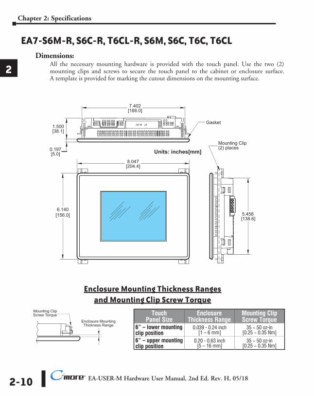
EA7-S6M-R, S6C-R, T6CL-R, S6M, S6C, T6C, T6CLDimensions:
All the necessary mounting hardware is provided with the touch panel. Use the two (2) mounting clips and screws to secure the touch panel to the cabinet or enclosure surface. A template is provided for marking the cutout dimensions on the mounting surface.
1
2
3
4
5
6
7
8
9
10
11
12
13
14
a
b
C
d
Gasket
Mounting Clip(2) places
8.047[204.4]
6.140[156.0]
7.402[188.0]
1.500[38.1]
0.197[5.0] Units: inches[mm]
5.458[138.6]
Enclosure Mounting Thickness Ranges and Mounting Clip Screw Torque
Touch Panel Size
Enclosure Thickness Range
Mounting Clip Screw Torque
6” – lower mounting clip position
0.039 - 0.24 inch [1 – 6 mm]
35 ~ 50 oz-in [0.25 ~ 0.35 Nm]
6” – upper mounting clip position
0.20 - 0.63 inch [5 – 16 mm]
35 ~ 50 oz-in [0.25 ~ 0.35 Nm]
Enclosure MountingThickness Range
Mounting ClipScrew Torque
EA-USER-M Hardware User Manual, 2nd Ed. Rev. H, 05/18 2-11
Chapter 2: Specifications
1
2
3
4
5
6
7
8
9
10
11
12
13
14
A
B
C
D
®
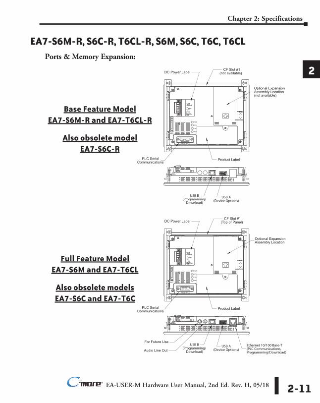
EA7-S6M-R, S6C-R, T6CL-R, S6M, S6C, T6C, T6CLPorts & Memory Expansion: 1
2
3
4
5
6
7
8
9
10
11
12
13
14
a
b
C
d
USB A(Device Options)
USB B(Programming/
Download)
PLC SerialCommunications
PWR
CPU
TxD
RxD
IOIOI–PLC
BATT
DC Power Label
Product Label
CF Slot #1(not available)
Optional ExpansionAssembly Location(not available)
USB A(Device Options)
USB B(Programming/
Download)
For Future Use
Audio Line Out
PLC SerialCommunications
DC Power Label
Product Label
Ethernet 10/100 Base-T(PLC Communications,Programming/Download)
CF Slot #1(Top of Panel)
Optional ExpansionAssembly Location
PWR
CPU
TxD
RxD
IOIOI–PLC
BATT
Base Feature Model EA7-S6M-R and EA7-T6CL-R
Also obsolete model EA7-S6C-R
Full Feature Model EA7-S6M and EA7-T6CL
Also obsolete models EA7-S6C and EA7-T6C
EA-USER-M Hardware User Manual, 2nd Ed. Rev. H, 05/182-12
Chapter 2: Specifications
1
2
3
4
5
6
7
8
9
10
11
12
13
14
A
B
C
D
®
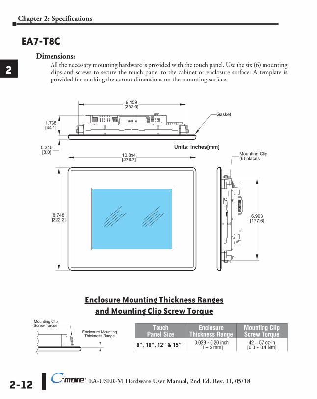
EA7-T8CDimensions:
All the necessary mounting hardware is provided with the touch panel. Use the six (6) mounting clips and screws to secure the touch panel to the cabinet or enclosure surface. A template is provided for marking the cutout dimensions on the mounting surface.
1
2
3
4
5
6
7
8
9
10
11
12
13
14
a
b
C
d
9.159[232.6]
1.738[44.1]
0.315[8.0]
8.748[222.2]
6.993[177.6]
10.894[276.7]
Mounting Clip(6) places
Gasket
Units: inches[mm]
Touch Panel Size
Enclosure Thickness Range
Mounting Clip Screw Torque
8”, 10”, 12” & 15” 0.039 - 0.20 inch [1 – 5 mm]
42 ~ 57 oz-in [0.3 ~ 0.4 Nm]
Enclosure Mounting Thickness Ranges and Mounting Clip Screw Torque
Enclosure MountingThickness Range
Mounting ClipScrew Torque
EA-USER-M Hardware User Manual, 2nd Ed. Rev. H, 05/18 2-13
Chapter 2: Specifications
1
2
3
4
5
6
7
8
9
10
11
12
13
14
A
B
C
D
®
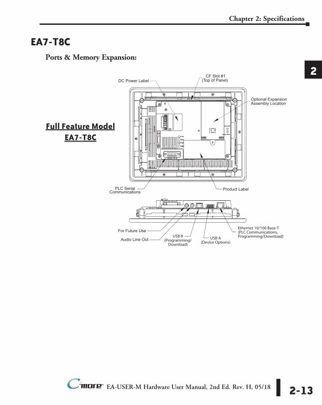
EA7-T8CPorts & Memory Expansion: 1
2
3
4
5
6
7
8
9
10
11
12
13
14
a
b
C
d
DC Power Label
Product Label
USB A(Device Options)
USB B(Programming/
Download)
For Future Use
Audio Line Out
PLC SerialCommunications
Ethernet 10/100 Base-T(PLC Communications,Programming/Download)
CF Slot #1(Top of Panel)
Optional ExpansionAssembly Location
Full Feature Model EA7-T8C
EA-USER-M Hardware User Manual, 2nd Ed. Rev. H, 05/182-14
Chapter 2: Specifications
1
2
3
4
5
6
7
8
9
10
11
12
13
14
A
B
C
D
®
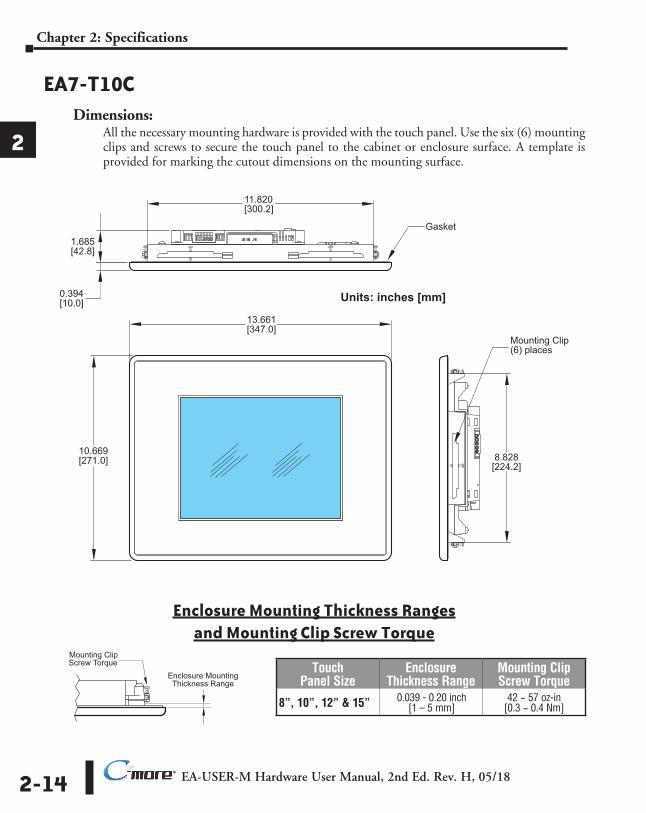
EA7-T10CDimensions:
All the necessary mounting hardware is provided with the touch panel. Use the six (6) mounting clips and screws to secure the touch panel to the cabinet or enclosure surface. A template is provided for marking the cutout dimensions on the mounting surface.
1
2
3
4
5
6
7
8
9
10
11
12
13
14
a
b
C
d
13.661[347.0]
11.820[300.2]
1.685[42.8]
0.394[10.0]
10.669[271.0] 8.828
[224.2]
Gasket
Mounting Clip(6) places
Units: inches [mm]
Touch Panel Size
Enclosure Thickness Range
Mounting Clip Screw Torque
8”, 10”, 12” & 15” 0.039 - 0.20 inch [1 – 5 mm]
42 ~ 57 oz-in [0.3 ~ 0.4 Nm]
Enclosure Mounting Thickness Ranges and Mounting Clip Screw Torque
Enclosure MountingThickness Range
Mounting ClipScrew Torque
EA-USER-M Hardware User Manual, 2nd Ed. Rev. H, 05/18 2-15
Chapter 2: Specifications
1
2
3
4
5
6
7
8
9
10
11
12
13
14
A
B
C
D
®
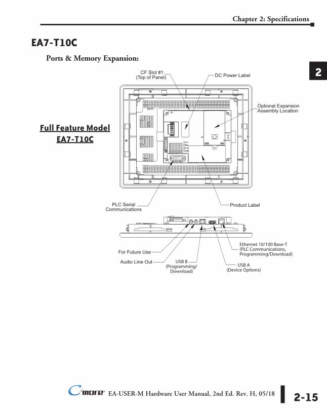
EA7-T10CPorts & Memory Expansion: 1
2
3
4
5
6
7
8
9
10
11
12
13
14
a
b
C
d
DC Power Label
Product Label
USB A(Device Options)
USB B(Programming/
Download)
For Future Use
Audio Line Out
PLC SerialCommunications
Ethernet 10/100 Base-T(PLC Communications,Programming/Download)
CF Slot #1(Top of Panel)
Optional ExpansionAssembly Location
Full Feature Model EA7-T10C
EA-USER-M Hardware User Manual, 2nd Ed. Rev. H, 05/182-16
Chapter 2: Specifications
1
2
3
4
5
6
7
8
9
10
11
12
13
14
A
B
C
D
®
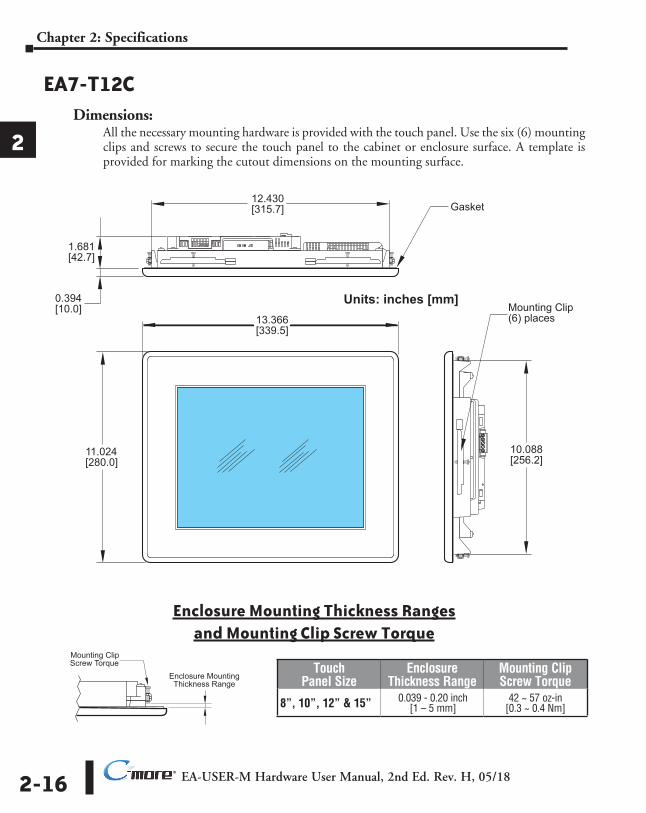
EA7-T12CDimensions:
All the necessary mounting hardware is provided with the touch panel. Use the six (6) mounting clips and screws to secure the touch panel to the cabinet or enclosure surface. A template is provided for marking the cutout dimensions on the mounting surface.
1
2
3
4
5
6
7
8
9
10
11
12
13
14
a
b
C
d
13.366[339.5]
11.024[280.0]
12.430[315.7]
1.681[42.7]
0.394[10.0]
Gasket
Mounting Clip(6) places
10.088[256.2]
Units: inches [mm]
Touch Panel Size
Enclosure Thickness Range
Mounting Clip Screw Torque
8”, 10”, 12” & 15” 0.039 - 0.20 inch [1 – 5 mm]
42 ~ 57 oz-in [0.3 ~ 0.4 Nm]
Enclosure Mounting Thickness Ranges and Mounting Clip Screw Torque
Enclosure MountingThickness Range
Mounting ClipScrew Torque
EA-USER-M Hardware User Manual, 2nd Ed. Rev. H, 05/18 2-17
Chapter 2: Specifications
1
2
3
4
5
6
7
8
9
10
11
12
13
14
A
B
C
D
®
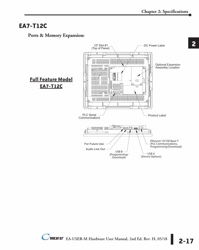
EA7-T12CPorts & Memory Expansion: 1
2
3
4
5
6
7
8
9
10
11
12
13
14
a
b
C
d
DC Power Label
Product Label
USB A(Device Options)
USB B(Programming/
Download)
For Future Use
Audio Line Out
PLC SerialCommunications
Ethernet 10/100 Base-T(PLC Communications,Programming/Download)
CF Slot #1(Top of Panel)
Optional ExpansionAssembly Location
Full Feature Model EA7-T12C
EA-USER-M Hardware User Manual, 2nd Ed. Rev. H, 05/182-18
Chapter 2: Specifications
1
2
3
4
5
6
7
8
9
10
11
12
13
14
A
B
C
D
®
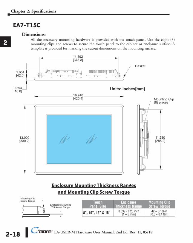
EA7-T15CDimensions:
All the necessary mounting hardware is provided with the touch panel. Use the eight (8) mounting clips and screws to secure the touch panel to the cabinet or enclosure surface. A template is provided for marking the cutout dimensions on the mounting surface.
1
2
3
4
5
6
7
8
9
10
11
12
13
14
a
b
C
d
Units: inches[mm]16.748[425.4]
13.000[330.2]
14.892[378.3]
1.654[42.0]
0.394[10.0]
11.230[285.2]
Gasket
Mounting Clip(8) places
Touch Panel Size
Enclosure Thickness Range
Mounting Clip Screw Torque
8”, 10”, 12” & 15” 0.039 - 0.20 inch [1 – 5 mm]
42 ~ 57 oz-in [0.3 ~ 0.4 Nm]
Enclosure Mounting Thickness Ranges and Mounting Clip Screw Torque
Enclosure MountingThickness Range
Mounting ClipScrew Torque
EA-USER-M Hardware User Manual, 2nd Ed. Rev. H, 05/18 2-19
Chapter 2: Specifications
1
2
3
4
5
6
7
8
9
10
11
12
13
14
A
B
C
D
®
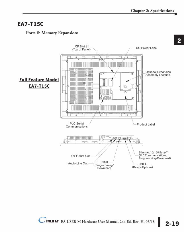
EA7-T15CPorts & Memory Expansion: 1
2
3
4
5
6
7
8
9
10
11
12
13
14
a
b
C
d
DC Power Label
Product Label
USB A(Device Options)
USB B(Programming/
Download)
For Future Use
Audio Line Out
PLC SerialCommunications
Ethernet 10/100 Base-T(PLC Communications,Programming/Download)
CF Slot #1(Top of Panel)
Optional ExpansionAssembly Location
Full Feature Model EA7-T15C
EA-USER-M Hardware User Manual, 2nd Ed. Rev. H, 05/182-20
Chapter 2: Specifications
1
2
3
4
5
6
7
8
9
10
11
12
13
14
A
B
C
D
®
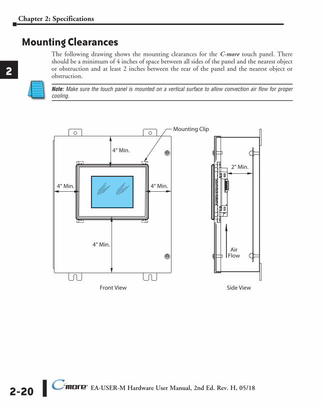
Mounting ClearancesThe following drawing shows the mounting clearances for the C-more touch panel. There should be a minimum of 4 inches of space between all sides of the panel and the nearest object or obstruction and at least 2 inches between the rear of the panel and the nearest object or obstruction.
Note: Make sure the touch panel is mounted on a vertical surface to allow convection air flow for proper cooling.
1
2
3
4
5
6
7
8
9
10
11
12
13
14
a
b
C
d
Mounting Clip
Front View Side View
4“ Min.
4“ Min.
4“ Min.
4“ Min.
2“ Min.
AirFlow
EA-USER-M Hardware User Manual, 2nd Ed. Rev. H, 05/18 2-21
Chapter 2: Specifications
1
2
3
4
5
6
7
8
9
10
11
12
13
14
A
B
C
D
®
1
2
3
4
5
6
7
8
9
10
11
12
13
14
a
b
C
d
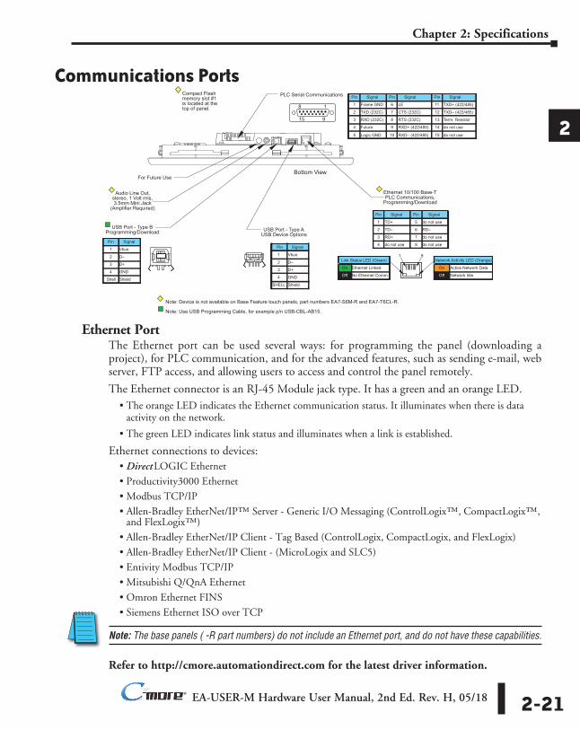
Communications Ports
Ethernet PortThe Ethernet port can be used several ways: for programming the panel (downloading a project), for PLC communication, and for the advanced features, such as sending e-mail, web server, FTP access, and allowing users to access and control the panel remotely.
The Ethernet connector is an RJ-45 Module jack type. It has a green and an orange LED.• The orange LED indicates the Ethernet communication status. It illuminates when there is data
activity on the network.
• The green LED indicates link status and illuminates when a link is established.
Ethernet connections to devices:• Direct LOGIC Ethernet• Productivity3000 Ethernet
• Modbus TCP/IP• Allen-Bradley EtherNet/IP™ Server - Generic I/O Messaging (ControlLogix™, CompactLogix™,
and FlexLogix™)
• Allen-Bradley EtherNet/IP Client - Tag Based (ControlLogix, CompactLogix, and FlexLogix)
• Allen-Bradley EtherNet/IP Client - (MicroLogix and SLC5)• Entivity Modbus TCP/IP
• Mitsubishi Q/QnA Ethernet• Omron Ethernet FINS• Siemens Ethernet ISO over TCP
Note: The base panels ( -R part numbers) do not include an Ethernet port, and do not have these capabilities.
Refer to http://cmore.automationdirect.com for the latest driver information.
For Future Use
Audio Line Out, stereo, 1 Volt rms, 3.5mm Mini Jack
(Amplifier Required)
USB Port - Type B Programming/Download USB Port - Type A
USB Device Options
Ethernet 10/100 Base-T PLC Communications,
Programming/Download
1 8 2 1 3 4 2 1
3 4
8 1
15 9
Pin Signal
1 Frame GND
TXD (232C)
RXD (232C)
Future
2
3
4
5 Logic GND
Pin Signal Pin Signal
6 LE
CTS (232C)
RTS (232C)
RXD+ (422/485)
7
8
9
10 RXD– (422/485)
11 TXD+ (422/485)
TXD– (422/485)
Term. Resistor
do not use
12
13
14
15 do not use
Pin Signal
1 TD+
TD–
RD+
do not use
2
3
4
Pin Signal
5 do not use
RD–
do not use
do not use
6
7
8 Pin Signal
1 Vbus
D–
D+
GND
2
3
4
Pin Signal
1 Vbus
D–
D+
GND
2
3
4
Shield Shell
PLC Serial Communications
Network Activity LED (Orange)
On Active Network Data
Network Idle Off
Link Status LED (Green)
On Ethernet Linked
No Ethernet Comm. Off
Bottom View
Note: Device is not available on Base Feature touch panels, part numbers EA7-S6M-R and EA7-T6CL-R.
Compact Flash memory slot #1 is located at the top of panel.
Note: Use USB Programming Cable, for example p/n USB-CBL-AB15.
ShieldSHELL
EA-USER-M Hardware User Manual, 2nd Ed. Rev. H, 05/182-22
Chapter 2: Specifications
1
2
3
4
5
6
7
8
9
10
11
12
13
14
A
B
C
D
®
Communications Ports (cont’d)USB Port B
Program C-more via the USB programming port. It’s fast and easy, with no baud rate settings, parity, or stop bits to worry about. We stock standard USB cables for your convenience, such as part no. USB-CBL-AB15. USB Port B can be used to upload or download projects to and from a PC (personnel computer).
USB Port AThe Universal Serial Bus (USB) type A port is a standard feature for all models and can be used to connect various USB 1.1 HID (Human Input Device) devices to the panel, such as:
• USB pen drives• USB keyboards• USB barcode scanners• USB card scanners
C-more can log data to the USB pen drive as well as load projects to the panel from the pen drive. You can also back up project files and panel firmware.
Sound Interface (Audio Line Out)When attached to an amplifier and speaker(s), C-more can play warning sounds, or pre-recorded messages such as: “conveyor is jammed”. C-more supports WAV type files. The output is stereo. See the next page for the WAV file specifications. Various “Objects” in the C-more programming software support sounds. Sound files are stored in the sound library. See the C-more programming software help support for additional details.
PLC PortThe PLC port is an RS-232C, RS-422A or RS-485A female 15-pin D-sub connector. Use this port for serial connections to PLCs. The port supports the following PLC protocols:
• All AutomationDirect.com PLCs: Productivity3000 CLICK Direct LOGIC K-sequence Direct NET Modbus (Koyo Addressing)
• Allen Bradley: DF1 Full & Half Duplex DF1 Full & Half Duplex - Tag Based PLC5 DF1 DH485
• Modbus RTU • Entivity Modbus RTU • GE SNPX (90/30, 90/70, Micro 90, VersaMax Micro) • Omron: Host Link (C200 Adapter, C500) FINS (CJ1, CS1) • Mitsubishi Melsec FX QnA • Siemens PPI (S7-200 CPU)
1
2
3
4
5
6
7
8
9
10
11
12
13
14
a
b
C
d
EA-USER-M Hardware User Manual, 2nd Ed. Rev. H, 05/18 2-23
Chapter 2: Specifications
1
2
3
4
5
6
7
8
9
10
11
12
13
14
A
B
C
D
®
1
2
3
4
5
6
7
8
9
10
11
12
13
14
a
b
C
d
Audio WAV File SpecificationsThe C-more Audio Line Out port supports the following WAV file specifications:
Audio Format (codec): PCM
Audio Sample Rate: 11 kHz, 22 kHz or 44 kHz
Channels: 1 (mono) or 2 (stereo)
Audio Sample Size: 8-bit or 16-bit
EA-USER-M Hardware User Manual, 2nd Ed. Rev. H, 05/182-24
Chapter 2: Specifications
1
2
3
4
5
6
7
8
9
10
11
12
13
14
A
B
C
D
®
1
2
3
4
5
6
7
8
9
10
11
12
13
14
a
b
C
d
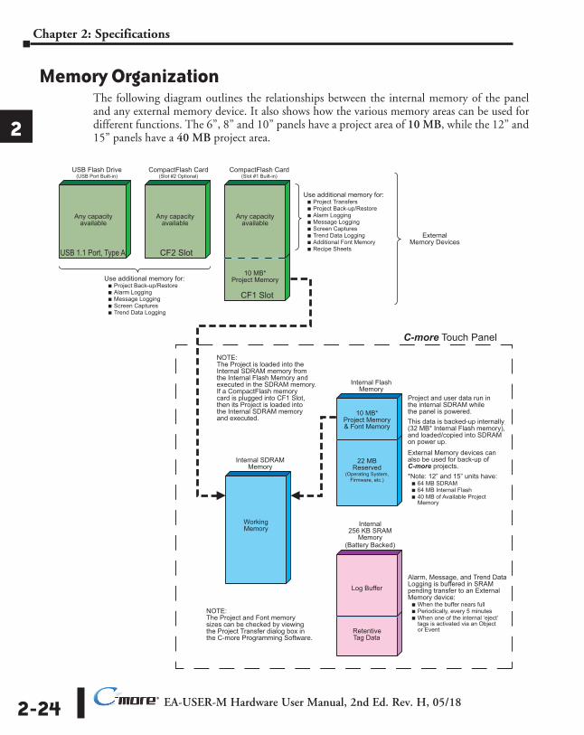
Memory OrganizationThe following diagram outlines the relationships between the internal memory of the panel and any external memory device. It also shows how the various memory areas can be used for different functions. The 6”, 8” and 10” panels have a project area of 10 MB, while the 12” and 15” panels have a 40 MB project area.
10 MB* Project Memory & Font Memory
22 MB Reserved
(Operating System, Firmware, etc.)
Log Buffer
Retentive Tag Data
Project and user data run in the internal SDRAM while the panel is powered. This data is backed-up internally (32 MB* Internal Flash memory), and loaded/copied into SDRAM on power up. External Memory devices can also be used for back-up of C-more projects. *Note: 12” and 15” units have: ■ 64 MB SDRAM ■ 64 MB Internal Flash ■ 40 MB of Available Project Memory
Alarm, Message, and Trend Data Logging is buffered in SRAM pending transfer to an External Memory device: ■ When the buffer nears full ■ Periodically, every 5 minutes ■ When one of the internal ‘eject’ tags is activated via an Object or Event
Use additional memory for: ■ Project Back-up/Restore ■ Alarm Logging ■ Message Logging ■ Screen Captures ■ Trend Data Logging
Internal 256 KB SRAM
Memory (Battery Backed)
CompactFlash Card (Slot #1 Built-in)
USB Flash Drive(USB Port Built-in)
CompactFlash Card (Slot #2 Optional)
Internal Flash Memory
Any capacityavailable
Any capacity available
Any capacity available
Use additional memory for: ■ Project Transfers ■ Project Back-up/Restore ■ Alarm Logging ■ Message Logging ■ Screen Captures ■ Trend Data Logging ■ Additional Font Memory ■ Recipe Sheets
CF1 Slot
CF2 Slot USB 1.1 Port, Type A
10 MB* Project Memory
Working Memory
Internal SDRAM Memory
NOTE: The Project is loaded into the Internal SDRAM memory from the Internal Flash Memory and executed in the SDRAM memory. If a CompactFlash memory card is plugged into CF1 Slot, then its Project is loaded into the Internal SDRAM memory and executed.
External Memory Devices
C-more Touch Panel
NOTE: The Project and Font memory sizes can be checked by viewing the Project Transfer dialog box in the C-more Programming Software.
EA-USER-M Hardware User Manual, 2nd Ed. Rev. H, 05/18 2-25
Chapter 2: Specifications
1
2
3
4
5
6
7
8
9
10
11
12
13
14
A
B
C
D
®
1
2
3
4
5
6
7
8
9
10
11
12
13
14
a
b
C
d
Handling External Memory DevicesConsider the following to prevent data error risk when utilizing data logging.
• Do not turn off power to the C-more touch panel at any time the external memory device is being accessed.
• Do not remove any external memory device when the device is being accessed by the touch panel.
Note: A system tag, such as SYS %device% WriteStatus can be used to detect when the external memory device is being accessed. See the C-more programming software on-line help for additional information on System Tag Names.
• If a CompactFlash memory card is plugged into the CF1 slot while the panel is running, the project will continue to run from the project that is currently in the internal SDRAM. If power is cycled and there is a good project stored on the CompactFlash, then that project will be loaded into the internal SDRAM and ran.
• Be sure to backup the memory device at regular intervals.
• A CompactFlash memory card plugged into the CF1 slot that includes a project that is being run cannot be used for backup.
• If you suspect the memory device is bad, you may want to use a PC to re-format the device, or use a known good memory device.
Note: The C-more touch panel requires that all external memory devices be formatted with a FAT or FAT32 file system. The FAT file system is recommended for better performance.
• The number of times the memory device can be written to is limited, approximately 300,000 times. Consequently, frequent writing at short intervals may shorten the service life of the memory device. Try to use as long as possible sampling times for logging data to reduce the amount of times the memory device is accessed.
EA-USER-M Hardware User Manual, 2nd Ed. Rev. H, 05/182-26
Chapter 2: Specifications
1
2
3
4
5
6
7
8
9
10
11
12
13
14
A
B
C
D
®
1
2
3
4
5
6
7
8
9
10
11
12
13
14
a
b
C
d
Power Loss Detection and Power Retention PeriodIt is important to have an understanding of how the touch panel handles power loss as it applies to data logging and retentive name tag data. The C-more touch panel system CPU will receive a power loss interrupt signal when the incoming DC voltage level drops below 19.2 VDC. If using the optional AC/DC Power Adapter, EA-AC, then an interrupt signal will occur when the incoming AC voltage level drops below 58 VAC (+/- 5%). When power loss is detected, the backlight will turn off immediately to allow extending the power retention period. Any logging to either CompactFlash memory or an USB pen drive will also stop. This will allow time to complete writing any data to the internal 256 KB SRAM. The 256 KB SRAM along with CPU Date/Time registers are battery backed.
Because the 24 VDC power retention time period is very short, only data backup to the internal 256 KB SRAM memory buffer can occur. When power is restored, the contents of the SRAM will be written to the selected memory storage device.
Data Logging Function and Logging MediaConsidering the power retention period and the CF card write performance, the EA-CF-CARD memory card is recommended to minimize data loss. It is also recommended to further reduce the risk of losing data, a uninterruptible power supply (UPS) should be used to provide power to the touch panel.
Data Logging - Memory Device FullThe following explains what occurs when logging data from an object, such as Line Trending, and the memory device becomes full. The memory device can be a USB pen drive plugged into the USB port, or a CompactFlash memory card plugged into location CF1 or CF2.
The answer is when the memory device that is being used for logging is full, the panel will stop writing to the log and a RTE-001 Runtime Error will be displayed on the screen. The displayed error message will read “Log Failed. Not enough Memory Space in %Device%”. (%Device% can be USB, CF1, or CF2.) The data logging object will continue to execute.
The user can monitor the System Tag “SYS %DEVICE% FreeMemory” with the Event Manager, and display a message to the operator to warn when the memory device is close to full.
The user can also use a Pushbutton object with the tag “SYS Copy Log to %Device%” to copy ALL logs on ALL other devices to %Device% and therefore save the current data.
For example, if the application is logging to CF1 and CF2, the user can monitor “SYS CF1 FreeMemory” and “SYS CF2 FreeMemory” in the Event Manager. When the value of either gets below a set value in the Event Manager, then the Event Manger can issue an Alarm, send an email, etc. The operator can then insert a USB pen drive into the panel’s USB port, and press a pushbutton that is configured with System Tag “SYS Copy Log to USB”. This action will copy all of the logged data to the USB pen drive from both CF1 and CF2. The operator can then use the System Setup Screen’s Memory selection to clear both CompactFlash CF1 and CF2.
This example can work with different combinations of the memory devices, but the preferred method is using a USB pen drive because it is the easiest device to insert and remove.
EA-USER-M Hardware User Manual, 2nd Ed. Rev. H, 05/18 2-27
Chapter 2: Specifications
1
2
3
4
5
6
7
8
9
10
11
12
13
14
A
B
C
D
®
1
2
3
4
5
6
7
8
9
10
11
12
13
14
a
b
C
d
Chemical CompatibilityThe C-more touch panels comprise three different materials that may be exposed to outside elements: a gasket, a screen sheet and a bezel.
The C-more panel serial number can be found on the label on the back of the panel. It has the format MODEL NUMBER + yymddBsss. The characters yym represent the year and month of manufacture. These are the characters that determine the materials used in construction of your panel as follows:
All panel gaskets are Silicone
Chemical compatibility tables begin on the next page.
Panel Size Date Code Screen Sheet Material
Bezel Frame Material
6 inch05m through 077 PET
ABS
078 through 112 PC
113 through current PET
8 inch05m through 077 PET
078 through 082PC
083 through current PPE/PS
10 inch05m through 077 PET
ABS078 through 081
PC082 through current PPE/PS
12 and 15 inch
05m through 077 PETABS
078 through 081PC
082 through 096PPE/PS
097 through current PET
EA-USER-M Hardware User Manual, 2nd Ed. Rev. H, 05/182-28
Chapter 2: Specifications
1
2
3
4
5
6
7
8
9
10
11
12
13
14
A
B
C
D
®
1
2
3
4
5
6
7
8
9
10
11
12
13
14
a
b
C
d
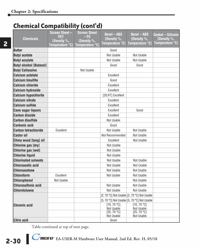
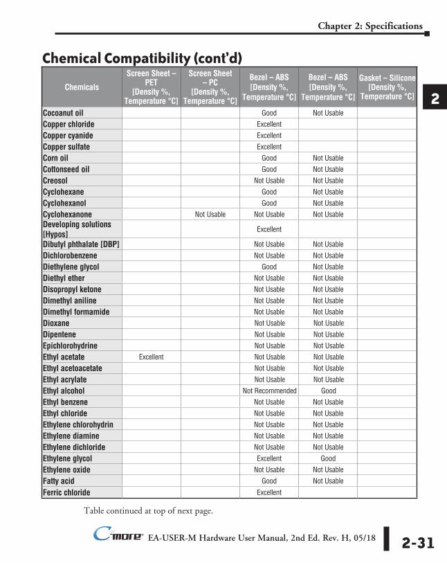
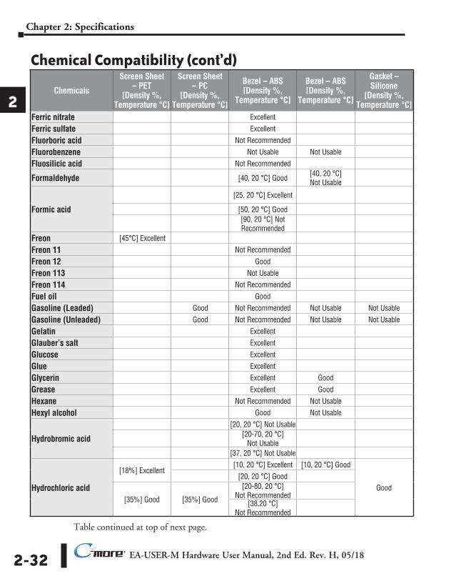
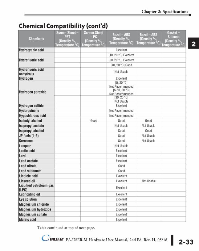
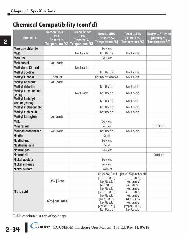
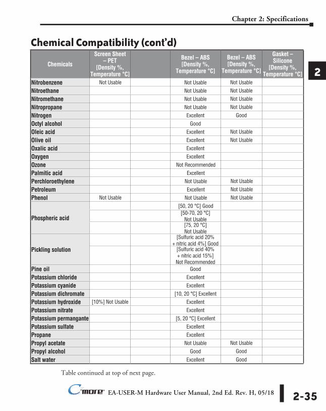
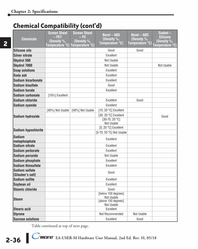
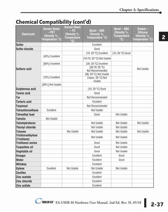
Chemical Compatibility (cont’d) The following tables are provided to make you aware of the general compatibility between chemicals that may be present in your work environment and the various materials used in the manufacture of the panel. Use the table to determine those chemicals that are safe to use around your C-more touch panel and those that may harm it. The tables are made up of specifications provided by the manufacturer of the listed material. The tables rate these chemicals as either Excellent, Good, Not Recommended, or Not Usable. Because the ratings are for ideal conditions at room temperature, consider all factors when evaluating your application. Areas left blank have not been tested by the manufacturer and therefore information of compatibility is not available.
The values in [brackets] represent the chemical’s density at room temperature, 20 °C.
Table continued at top of next page.
Chemicals
Screen Sheet – PET
[Density %, Temperature °C]
Screen Sheet – PC
[Density %, Temperature °C]
Bezel – ABS [Density %,
Temperature °C]
Bezel – PPE / PS [Density %,
Temperature °C]
Gasket – Silicone
[Density %, Temperature °C]
Acetaldehyde Not Recommended Not Usable
Acetic Acid
[10, 20 °C] Excellent[10, 20 °C] Excellent
[Glacial] Excellent [50, 20 °C] Not Usable[50-70, 20 °C]
Not Usable[100, 20 °C] Not Usable
Acetic anhydride Not Recommended
Acetone Excellent Not Usable Not Usable Not Usable
Acetophenone Not Usable Not Usable
Acetylene Excellent
Acrylonitrile Not Recommended Not Usable
Alcohol - Butyl Ether Excellent
Alcohol - Ethanol Excellent
Alcohol - Isopropyl Excellent
Alums NH3, Cr, K Excellent
Aluminum acetate Excellent
Aluminum bromide Good
Aluminum chloride Good
Aluminum nitrate Excellent
Aluminum sulfate ExcellentAmmonia [anhydrous] (10%)
Good Good Good
Ammonia gas [cold] Good
Ammonia liquid Good

EA-USER-M Hardware User Manual, 2nd Ed. Rev. H, 05/18 2-29
Chapter 2: Specifications
1
2
3
4
5
6
7
8
9
10
11
12
13
14
A
B
C
D
®
Chemical Compatibility (cont’d)
Table continued at top of next page.
1
2
3
4
5
6
7
8
9
10
11
12
13
14
a
b
C
d
Chemicals
Screen Sheet – PET
[Density %, Temperature °C]
Screen Sheet – PC
[Density %, Temperature °C]
Bezel – ABS [Density %,
Temperature °C]
Bezel – ABS [Density %,
Temperature °C]
Gasket – Silicone [Density %,
Temperature °C]
Ammonia water[12%] Not Usable [12%] Not Usable[28%] Not Usable [28%] Not Usable
Ammonium carbonate Excellent
Ammonium chloride ExcellentAmmonium hydroxide [ammonia water]
Excellent
Ammonium nitrate Excellent
Ammonium nitrite Excellent
Ammonium persulfate Excellent
Ammonium phosphate Excellent
Ammonium sulfate Excellent
Amyl acetate Not Usable
Amyl alcohol Good
Aniline dyes Not Recommended
Animal oil [lard] Good
Aqua regia Not Usable
Arsenic acid Not Recommended
Asphalt Excellent
Barium chloride Excellent
Barium hydroxide Excellent
Barium sulfate Excellent
Barium sulfide Excellent
Beer Excellent Good
Beet sugar liquors Excellent
Benzaldehyde Not Recommended Not Usable
Benzene [Benzol] Not Recommended Not Usable
Benzene Excellent Not Usable Not Usable
Benzine Not Usable Not Usable
Benzyl alcohol Not Recommended Not Usable
Benzyl benzoate Not Usable Not Usable
Benzyl chloride Not Usable Not Usable
Borax Excellent
Boric acid Good
Bromine Not Usable
Butane Excellent
EA-USER-M Hardware User Manual, 2nd Ed. Rev. H, 05/182-30
Chapter 2: Specifications
1
2
3
4
5
6
7
8
9
10
11
12
13
14
A
B
C
D
®
1
2
3
4
5
6
7
8
9
10
11
12
13
14
a
b
C
d
Chemical Compatibility (cont’d)
Table continued at top of next page.
Chemicals
Screen Sheet – PET
[Density %, Temperature °C]
Screen Sheet – PC
[Density %, Temperature °C]
Bezel – ABS [Density %,
Temperature °C]
Bezel – ABS [Density %,
Temperature °C]
Gasket – Silicone [Density %,
Temperature °C]
Butter Good
Butyl acetate Not Usable Not Usable
Butyl acrylate Not Usable Not Usable
Butyl alcohol [Butanol] Good Good
Butyl Cellosolve Not Usable
Calcium actetate Excellent
Calcium bisulfite Good
Calcium chloride Excellent
Calcium hydroxide Excellent
Calcium hypochlorite [20,RT] Excellent
Calcium nitrate Excellent
Calcium sulfide Excellent
Cane sugar liquors Excellent Good
Carbon dioxide Excellent
Carbon disulfide Not Usable
Carbonic acid Good
Carbon tetrachloride Excellent Not Usable Not Usable
Castor oil Not Recommended Not Usable
China wood [tung] oil Excellent Not Usable
Chlorine gas [dry] Not Usable
Chlorine gas [wet] Not Usable
Chlorine liquid Not Usable
Chlorinated solvents Not Usable Not Usable
Chloroacetic acid Not Usable Not Usable
Chloroacetone Not Usable Not Usable
Chloroform Excellent Not Usable Not Usable
Chlorophenol Not Usable Not Usable
Chlorosulfonic acid Not Usable Not Usable
Chlorotoluene Not Usable Not Usable
Chromic acid
[2, 70 °C] Not Usable [2, 70 °C] Not Usable[5, 70 °C] Not Usable [5, 70 °C] Not Usable
[10, 70 °C] Not Usable
[10, 70 °C] Not Usable
[25, 70 °C] Not Usable
[25, 70 °C] Not Usable
Citric acid Good
EA-USER-M Hardware User Manual, 2nd Ed. Rev. H, 05/18 2-31
Chapter 2: Specifications
1
2
3
4
5
6
7
8
9
10
11
12
13
14
A
B
C
D
®
Chemical Compatibility (cont’d)
Table continued at top of next page.
1
2
3
4
5
6
7
8
9
10
11
12
13
14
a
b
C
d
Chemicals
Screen Sheet – PET
[Density %, Temperature °C]
Screen Sheet – PC
[Density %, Temperature °C]
Bezel – ABS [Density %,
Temperature °C]
Bezel – ABS [Density %,
Temperature °C]
Gasket – Silicone [Density %,
Temperature °C]
Cocoanut oil Good Not Usable
Copper chloride Excellent
Copper cyanide Excellent
Copper sulfate Excellent
Corn oil Good Not Usable
Cottonseed oil Good Not Usable
Creosol Not Usable Not Usable
Cyclohexane Good Not Usable
Cyclohexanol Good Not Usable
Cyclohexanone Not Usable Not Usable Not UsableDeveloping solutions [Hypos]
Excellent
Dibutyl phthalate [DBP] Not Usable Not Usable
Dichlorobenzene Not Usable Not Usable
Diethylene glycol Good Not Usable
Diethyl ether Not Usable Not Usable
Disopropyl ketone Not Usable Not Usable
Dimethyl aniline Not Usable Not Usable
Dimethyl formamide Not Usable Not Usable
Dioxane Not Usable Not Usable
Dipentene Not Usable Not Usable
Epichlorohydrine Not Usable Not Usable
Ethyl acetate Excellent Not Usable Not Usable
Ethyl acetoacetate Not Usable Not Usable
Ethyl acrylate Not Usable Not Usable
Ethyl alcohol Not Recommended Good
Ethyl benzene Not Usable Not Usable
Ethyl chloride Not Usable Not Usable
Ethylene chlorohydrin Not Usable Not Usable
Ethylene diamine Not Usable Not Usable
Ethylene dichloride Not Usable Not Usable
Ethylene glycol Excellent Good
Ethylene oxide Not Usable Not Usable
Fatty acid Good Not Usable
Ferric chloride Excellent
EA-USER-M Hardware User Manual, 2nd Ed. Rev. H, 05/182-32
Chapter 2: Specifications
1
2
3
4
5
6
7
8
9
10
11
12
13
14
A
B
C
D
®
1
2
3
4
5
6
7
8
9
10
11
12
13
14
a
b
C
d
Chemical Compatibility (cont’d)
Table continued at top of next page.
Chemicals
Screen Sheet – PET
[Density %, Temperature °C]
Screen Sheet – PC
[Density %, Temperature °C]
Bezel – ABS [Density %,
Temperature °C]
Bezel – ABS [Density %,
Temperature °C]
Gasket – Silicone
[Density %, Temperature °C]
Ferric nitrate Excellent
Ferric sulfate Excellent
Fluorboric acid Not Recommended
Fluorobenzene Not Usable Not Usable
Fluosilicic acid Not Recommended
Formaldehyde [40, 20 °C] Good [40, 20 °C] Not Usable
Formic acid
[25, 20 °C] Excellent
[50, 20 °C] Good[90, 20 °C] Not Recommended
Freon [45°C] Excellent
Freon 11 Not Recommended
Freon 12 Good
Freon 113 Not Usable
Freon 114 Not Recommended
Fuel oil Good
Gasoline (Leaded) Good Not Recommended Not Usable Not Usable
Gasoline (Unleaded) Good Not Recommended Not Usable Not Usable
Gelatin Excellent
Glauber’s salt Excellent
Glucose Excellent
Glue Excellent
Glycerin Excellent Good
Grease Excellent Good
Hexane Not Recommended Not Usable
Hexyl alcohol Good Not Usable
Hydrobromic acid
[20, 20 °C] Not Usable[20-70, 20 °C]
Not Usable[37, 20 °C] Not Usable
Hydrochloric acid
[18%] Excellent[10, 20 °C] Excellent [10, 20 °C] Good
Good[20, 20 °C] Good
[35%] Good [35%] Good
[20-80, 20 °C] Not Recommended
[38,20 °C] Not Recommended
EA-USER-M Hardware User Manual, 2nd Ed. Rev. H, 05/18 2-33
Chapter 2: Specifications
1
2
3
4
5
6
7
8
9
10
11
12
13
14
A
B
C
D
®
Chemical Compatibility (cont’d)
Table continued at top of next page.
1
2
3
4
5
6
7
8
9
10
11
12
13
14
a
b
C
d
Chemicals
Screen Sheet – PET
[Density %, Temperature °C]
Screen Sheet – PC
[Density %, Temperature °C]
Bezel – ABS [Density %,
Temperature °C]
Bezel – ABS [Density %,
Temperature °C]
Gasket – Silicone
[Density %, Temperature °C]
Hydrocyanic acid Excellent
Hydrofluoric acid[10, 20 °C] Excellent[20, 20 °C] Excellent
[40, 20 °C] GoodHydrofluoric acid anhydrous
Not Usable
Hydrogen Excellent
Hydrogen peroxide
[5, 20 °C] Not Recommended
[5-50, 20 °C] Not Recommended
[30, 20 °C] Not Usable
Hydrogen sulfide Excellent
Hydorquinone Not Recommended
Hypochlorous acid Not Recommended
Isobutyl alcohol Good Good Good
Isopropyl acetate Not Usable Not Usable
Isopropyl alcohol Good Good
JP fuels (1-6) Good Not Usable
Kerosene Good Not Usable
Lacquer Not Usable
Lactic acid Excellent
Lard Excellent
Lead acetate Excellent
Lead nitrate Good
Lead sulfamate Good
Linoleic acid Excellent
Linseed oil Excellent Not UsableLiquified petroleum gas [LPG]
Excellent
Lubricating oil Excellent
Lye solution Excellent
Magnesium chloride Excellent
Magnesium hydroxide Excellent
Magnesium sulfate Excellent
Maleic acid Excellent
EA-USER-M Hardware User Manual, 2nd Ed. Rev. H, 05/182-34
Chapter 2: Specifications
1
2
3
4
5
6
7
8
9
10
11
12
13
14
A
B
C
D
®
Chemical Compatibility (cont’d)
Chemicals
Screen Sheet – PET
[Density %, Temperature °C]
Screen Sheet – PC
[Density %, Temperature °C]
Bezel – ABS [Density %,
Temperature °C]
Bezel – ABS [Density %,
Temperature °C]
Gasket – Silicone [Density %,
Temperature °C]
Marcuric chloride Excellent
MEK Not Usable Not Usable Not Usable
Mercury Excellent
Metacresol Not Usable
Methylene Chloride Not Usable
Methyl acetate Not Usable Not Usable
Methyl alcohol Excellent Not Recommended Not Usable
Methyl Benzoate Not Usable
Methyl chloride Not Usable Not UsableMethyl ethyl ketone [MEK]
Not Usable Not Usable Not Usable
Methyl isobutyl ketone [MIBK]
Not Usable Not Usable
Methyl methacrylate Not Usable Not Usable
Methyl dichloride Not Usable Not Usable
Methyl Salicylate Not Usable
Milk Excellent
Mineral oil Excellent Excellent
Monochlorobenzene Not Usable Not Usable Not Usable
Naptha Good
Napthalene Excellent
Napthenic acid Good
Natural gas Excellent
Natural oil Excellent
Nickel acetate Excellent
Nickel chloride Excellent
Nickel sulfate Excellent
Nitric acid
[35%] Good
[10, 20 °C] Good [10, 20 °C] Not Usable[10-70, 20 °C]
Not Usable[10-70, 20 °C]
Not Usable[30, 20 °C] Not Usable
[30, 20 °C] Not Usable
[60%] Not Usable
[30-70, 20 °C] Not Usable
[30-70, 20 °C] Not Usable
[61.3, 20 °C] Not Usable
[61.3, 20 °C] Not Usable
[Vapor, 20 °C] Not Usable
[Vapor, 20 °C] Not Usable
Table continued at top of next page.
1
2
3
4
5
6
7
8
9
10
11
12
13
14
a
b
C
d
EA-USER-M Hardware User Manual, 2nd Ed. Rev. H, 05/18 2-35
Chapter 2: Specifications
1
2
3
4
5
6
7
8
9
10
11
12
13
14
A
B
C
D
®
Chemical Compatibility (cont’d)
Table continued at top of next page.
1
2
3
4
5
6
7
8
9
10
11
12
13
14
a
b
C
d
Chemicals
Screen Sheet – PET
[Density %, Temperature °C]
Bezel – ABS [Density %,
Temperature °C]
Bezel – ABS [Density %,
Temperature °C]
Gasket – Silicone
[Density %, Temperature °C]
Nitrobenzene Not Usable Not Usable Not Usable
Nitroethane Not Usable Not Usable
Nitromethane Not Usable Not Usable
Nitropropane Not Usable Not Usable
Nitrogen Excellent Good
Octyl alcohol Good
Oleic acid Excellent Not Usable
Olive oil Excellent Not Usable
Oxalic acid Excellent
Oxygen Excellent
Ozone Not Recommended
Palmitic acid Excellent
Perchloroethylene Not Usable Not Usable
Petroleum Excellent Not Usable
Phenol Not Usable Not Usable Not Usable
Phospheric acid
[50, 20 °C] Good[50-70, 20 °C]
Not Usable[75, 20 °C] Not Usable
Pickling solution
[Sulfuric acid 20% + nitric acid 4%] Good
[Sulfuric acid 40% + nitric acid 15%]
Not RecommendedPine oil Good
Potassium chloride Excellent
Potassium cyanide Excellent
Potassium dichromate [10, 20 °C] Excellent
Potassium hydroxide [10%] Not Usable Excellent
Potassium nitrate Excellent
Potassium permangante [5, 20 °C] Excellent
Potassium sulfate Excellent
Propane Excellent
Propyl acetate Not Usable Not Usable
Propyl alcohol Good Good
Salt water Excellent Good
EA-USER-M Hardware User Manual, 2nd Ed. Rev. H, 05/182-36
Chapter 2: Specifications
1
2
3
4
5
6
7
8
9
10
11
12
13
14
A
B
C
D
®
Chemical Compatibility (cont’d)
Table continued at top of next page.
1
2
3
4
5
6
7
8
9
10
11
12
13
14
a
b
C
d
Chemicals
Screen Sheet – PET
[Density %, Temperature °C]
Screen Sheet – PC
[Density %, Temperature °C]
Bezel – ABS [Density %,
Temperature °C]
Bezel – ABS [Density %,
Temperature °C]
Gasket – Silicone
[Density %, Temperature °C]
Silicone oils Good Good
Silver nitrate Excellent
Skydrol 500 Not Usable
Skydrol 7000 Not Usable Not Usable
Soap solutions Excellent
Soda ash Excellent
Sodium bicarbonate Excellent
Sodium bisulfate Good
Sodium borate Excellent
Sodium carbonate [10%] Excellent
Sodium chloride Excellent Good
Sodium cyanide Excellent
Sodium hydroxide
[40%] Not Usable [40%] Not Usable [10, 20 °C] Excellent
Good[30, 20 °C] Excellent[30-70, 20 °C]
Not Usable
Sodium hypochlorite[5, 20 °C] Excellent
[5-70, 20 °C] Not UsableSodium metaphosphate
Excellent
Sodium nitrate Excellent
Sodium perborate Excellent
Sodium peroxide Not Usable
Sodium phosphate Excellent
Sodium thiosulfate ExcellentSodium sulfate [Glauber’s salt]
Good
Sodium sulfite Excellent
Soybean oil Excellent
Stannic chloride Good
Steam
[below 150 degrees] Not Usable
[above 150 degrees] Not Usable
Stearic acid Excellent
Styrene Not Recommended Not Usable
Sucrose solutions Excellent Good
EA-USER-M Hardware User Manual, 2nd Ed. Rev. H, 05/18 2-37
Chapter 2: Specifications
1
2
3
4
5
6
7
8
9
10
11
12
13
14
A
B
C
D
®
Chemical Compatibility (cont’d)1
2
3
4
5
6
7
8
9
10
11
12
13
14
a
b
C
d
Chemicals
Screen Sheet – PET
[Density %, Temperature °C]
Screen Sheet – PC
[Density %, Temperature
°C]
Bezel – ABS [Density %,
Temperature °C]
Bezel – ABS [Density %, Temperature
°C]
Gasket – Silicone
[Density %, Temperature °C]
Sulfur Excellent
Sulfur dioxide Good
Sulfuric acid
[40%] Excellent[10, 20 °C] Excellent [10, 20 °C] Good
Not Usable
[10-70, 20 °C] Not Usable
[60%] Excellent [30, 20 °C] Excellent[30-70, 20 °C]
Not Recommended
[70%] Excellent[98, 20 °C] Not Usable
[Vapor, 20 °C] Not Usable
[80%] Not Usable
Sulpherous acid [10, 20 °C] Good
Tannic acid Good
Tar Not Recommended
Tartaric acid Excellent
Terpineol Not Recommended
Tetrachloroethane Excellent Not Usable
Tetraethyl lead Good Not Usable
Tetralin Not Usable
Tetrahydrofuran Not Usable Not Usable Not Usable
Thionyl chloride Not Usable Not Usable
Toluene Not Usable Not Usable Not Usable Not UsableTrichloroethylene [Trichlene]
Not Usable Not Usable
Triethanol amine Good Not Usable
Turpentine oil Good Not Usable
Vegetable oil Good Not Usable
Vinegar Excellent Good
Water Excellent Good
Whiskey Excellent
Xylene Excellent Not Usable Not Usable Not Usable
Zeolites Excellent
Zinc acetate Excellent
Zinc chloride Excellent
Zinc sulfate Excellent