c cure 800/8000 / c cure 9000 istar pro installation and
TRANSCRIPT

6 Technology Park DriveWestford, MA 01886-3140Fax: 978-577-4392 Phone: 978-577-4000http://www.swhouse.com
C•CURE 800/8000 / C•CURE 9000
iSTAR Pro
Installation and Configuration Guide

C•CURE and Software House are registered trademarks of Tyco International Ltd. and its respective companies.
The trademarks, logos, and service marks displayed on this document are registered in the United States [or other countries]. Any misuse of the trademarks is strictly prohibited and Tyco International Ltd. will aggressively enforce its intellectual property rights to the fullest extent of the law, including pursuit of criminal prosecution wherever necessary. All trademarks not owned by Tyco International Ltd. are the property of their respective owners, and are used with permission or allowed under applicable laws.
Product offerings and specifications are subject to change without notice. Actual products may vary from photos. Not all products include all features. Availability varies by region; contact your sales representative.
C•CURE 800-8000 / C•CURE 9000
Document Number: UM-063Revision Number: G8Release Date: July 2012
This manual is proprietary information of Software House. Unauthorized reproduction of any portion of this manual is prohibited. The material in this manual is for information purposes only. It is subject to change without notice. Software House assumes no responsibility for incorrect information this manual may contain. Copyright © 2012 by Tyco International Ltd. and its respective companies.
All rights reserved.

Table of Contents
Preface
How to Use this Manual . . . . . . . . . . . . . . . . . . . . . . . . . . . . . . . xii
Conventions . . . . . . . . . . . . . . . . . . . . . . . . . . . . . . . . . . . . . . . . .xiii
UL Listing . . . . . . . . . . . . . . . . . . . . . . . . . . . . . . . . . . . . . . . . . .xiv
FCC Class A Digital Device Limitations . . . . . . . . . . . . . . . . . .xiv
FCC Class B Notes . . . . . . . . . . . . . . . . . . . . . . . . . . . . . . . . . . . xv
Canadian Radio Emissions Requirements . . . . . . . . . . . . . . . . . . xv
CE Compliance . . . . . . . . . . . . . . . . . . . . . . . . . . . . . . . . . . . . . .xvi
Important Safety Information . . . . . . . . . . . . . . . . . . . . . . . . . . .xvi
Power Supply Information. . . . . . . . . . . . . . . . . . . . . . . . . . . . . xvii
Chapter 1 Introducing iSTAR Pro
iSTAR Pro Features . . . . . . . . . . . . . . . . . . . . . . . . . . . . . . . . . . .1-2
Network, Dialup, and Serial Connections . . . . . . . . . . . . . . . . . . . . 1-2Memory . . . . . . . . . . . . . . . . . . . . . . . . . . . . . . . . . . . . . . . . . . . . . . 1-2Cluster Configuration . . . . . . . . . . . . . . . . . . . . . . . . . . . . . . . . . . . 1-3Diagnostic Information . . . . . . . . . . . . . . . . . . . . . . . . . . . . . . . . . . 1-4Upgrading Firmware . . . . . . . . . . . . . . . . . . . . . . . . . . . . . . . . . . . . 1-4C•CURE Integration . . . . . . . . . . . . . . . . . . . . . . . . . . . . . . . . . . . . 1-5Backward Compatibility . . . . . . . . . . . . . . . . . . . . . . . . . . . . . . . . . 1-5
System Components . . . . . . . . . . . . . . . . . . . . . . . . . . . . . . . . . .1-6
Typical Installation . . . . . . . . . . . . . . . . . . . . . . . . . . . . . . . . . . . . . 1-6
The General Controller Module (GCM) . . . . . . . . . . . . . . . . . . .1-8
Features . . . . . . . . . . . . . . . . . . . . . . . . . . . . . . . . . . . . . . . . . . . . . . 1-8
iSTAR Pro Installation and Configuration Guide iii

Contents
iv
GCM Photograph . . . . . . . . . . . . . . . . . . . . . . . . . . . . . . . . . . . . . . . 1-9GGM Components Diagram . . . . . . . . . . . . . . . . . . . . . . . . . . . . . 1-10Component Description . . . . . . . . . . . . . . . . . . . . . . . . . . . . . . . . . 1-11
The Access Controller Module (ACM) . . . . . . . . . . . . . . . . . . 1-12
Features . . . . . . . . . . . . . . . . . . . . . . . . . . . . . . . . . . . . . . . . . . . . . 1-12ACM Components Diagram . . . . . . . . . . . . . . . . . . . . . . . . . . . . . 1-13Component Description . . . . . . . . . . . . . . . . . . . . . . . . . . . . . . . . . 1-14ACM Board Layout . . . . . . . . . . . . . . . . . . . . . . . . . . . . . . . . . . . . 1-14
ACM Capacities . . . . . . . . . . . . . . . . . . . . . . . . . . . . . . . . . . . . 1-15
Modules that Interface with iSTAR Pro . . . . . . . . . . . . . . . . . 1-16
Connecting Security Devices to the ACM. . . . . . . . . . . . . . . . 1-17
Inputs . . . . . . . . . . . . . . . . . . . . . . . . . . . . . . . . . . . . . . . . . . . . . . . 1-17Outputs . . . . . . . . . . . . . . . . . . . . . . . . . . . . . . . . . . . . . . . . . . . . . . 1-17Readers. . . . . . . . . . . . . . . . . . . . . . . . . . . . . . . . . . . . . . . . . . . . . . 1-18
iSTAR Tools . . . . . . . . . . . . . . . . . . . . . . . . . . . . . . . . . . . . . . 1-19
iSTAR Configuration Utility (ICU). . . . . . . . . . . . . . . . . . . . . . . . 1-19iSTAR Web-Based Diagnostic Utility. . . . . . . . . . . . . . . . . . . . . . 1-20
Chapter 2 iSTAR Pro Topology
iSTAR Pro Network Topology . . . . . . . . . . . . . . . . . . . . . . . . . 2-2
Lan and Wan Configurations . . . . . . . . . . . . . . . . . . . . . . . . . . . . . . 2-2Gateways and Firewalls . . . . . . . . . . . . . . . . . . . . . . . . . . . . . . . . . . 2-2IP Management Tools . . . . . . . . . . . . . . . . . . . . . . . . . . . . . . . . . . . 2-4Using NetBIOS and Fully Qualified Domain Names . . . . . . . . . . . 2-4
Cluster Configuration. . . . . . . . . . . . . . . . . . . . . . . . . . . . . . . . . 2-5
Master and Member Configuration . . . . . . . . . . . . . . . . . . . . . . . . . 2-5
Single Master and Alternate Master Configurations . . . . . . . . . 2-6
Single Master Configurations . . . . . . . . . . . . . . . . . . . . . . . . . . . . . 2-7Alternate Master Configurations . . . . . . . . . . . . . . . . . . . . . . . . . . . 2-7
Communication Paths . . . . . . . . . . . . . . . . . . . . . . . . . . . . . . . . 2-8
iSTAR Pro Installation and Configuration Guide

Contents
The Primary Communications Path. . . . . . . . . . . . . . . . . . . . . . . . . 2-8
Maintaining Cluster Communication. . . . . . . . . . . . . . . . . . . . 2-10
Single Master Configurations . . . . . . . . . . . . . . . . . . . . . . . . . . . . 2-10Alternate Master Configurations . . . . . . . . . . . . . . . . . . . . . . . . . . 2-11Communication Between Members and Master . . . . . . . . . . . . . . 2-12
Choosing Controllers for the Cluster . . . . . . . . . . . . . . . . . . . . 2-13
Planning the Communication Path. . . . . . . . . . . . . . . . . . . . . . 2-14
Planning Primary Communications. . . . . . . . . . . . . . . . . . . . . . . . 2-14Planning Secondary Communications. . . . . . . . . . . . . . . . . . . . . . 2-15
Chapter 3 Site Requirements
Pre-Installation . . . . . . . . . . . . . . . . . . . . . . . . . . . . . . . . . . . . . . 3-2
Equipment Check. . . . . . . . . . . . . . . . . . . . . . . . . . . . . . . . . . . . . . . 3-2Site Check . . . . . . . . . . . . . . . . . . . . . . . . . . . . . . . . . . . . . . . . . . . . 3-2Tools . . . . . . . . . . . . . . . . . . . . . . . . . . . . . . . . . . . . . . . . . . . . . . . . 3-3
Installation Requirements. . . . . . . . . . . . . . . . . . . . . . . . . . . . . . 3-4
Host System Requirements . . . . . . . . . . . . . . . . . . . . . . . . . . . . . . . 3-4iSTAR Pro Cabinet Requirements. . . . . . . . . . . . . . . . . . . . . . . . . . 3-4Environmental Requirements . . . . . . . . . . . . . . . . . . . . . . . . . . . . . 3-4Host Communication Baud Rate Requirements . . . . . . . . . . . . . . . 3-5Modem and Phone Line Requirements . . . . . . . . . . . . . . . . . . . . . . 3-5Power Requirements . . . . . . . . . . . . . . . . . . . . . . . . . . . . . . . . . . . . 3-5Ethernet Requirements. . . . . . . . . . . . . . . . . . . . . . . . . . . . . . . . . . 3-11Wiring Requirements. . . . . . . . . . . . . . . . . . . . . . . . . . . . . . . . . . . 3-12Avoiding Card Misreads . . . . . . . . . . . . . . . . . . . . . . . . . . . . . . . . 3-15RS-232 Requirements . . . . . . . . . . . . . . . . . . . . . . . . . . . . . . . . . . 3-16Grounding Requirements. . . . . . . . . . . . . . . . . . . . . . . . . . . . . . . . 3-16
Chapter 4 Hardware Installation
Installation Overview. . . . . . . . . . . . . . . . . . . . . . . . . . . . . . . . . 4-2
Procedure Overview . . . . . . . . . . . . . . . . . . . . . . . . . . . . . . . . . . . . 4-2
iSTAR Pro Installation and Configuration Guide v

Contents
vi
Mounting the Enclosure . . . . . . . . . . . . . . . . . . . . . . . . . . . . . . . 4-4
Static Electricity. . . . . . . . . . . . . . . . . . . . . . . . . . . . . . . . . . . . . . . . 4-4
Installing Flash Memory . . . . . . . . . . . . . . . . . . . . . . . . . . . . . . 4-7
Installing Batteries . . . . . . . . . . . . . . . . . . . . . . . . . . . . . . . . . . . 4-8
Connecting to the Host. . . . . . . . . . . . . . . . . . . . . . . . . . . . . . . 4-10
Primary and Secondary Connections . . . . . . . . . . . . . . . . . . . . . . . 4-10Connecting to the Host via the Network . . . . . . . . . . . . . . . . . . . . 4-10Connecting to the Host using RS-232 . . . . . . . . . . . . . . . . . . . . . . 4-12Connecting to the Host via Modem . . . . . . . . . . . . . . . . . . . . . . . . 4-15
Low Battery, Power Fail and Tamper Inputs . . . . . . . . . . . . . . 4-19
Connecting Inputs to P8. . . . . . . . . . . . . . . . . . . . . . . . . . . . . . . . . 4-19
Connecting AC Power . . . . . . . . . . . . . . . . . . . . . . . . . . . . . . 4-21
Installing modular boards. . . . . . . . . . . . . . . . . . . . . . . . . . . . . 4-22
Installing a modular GCM . . . . . . . . . . . . . . . . . . . . . . . . . . . . . . . 4-22Installing the first modular ACM. . . . . . . . . . . . . . . . . . . . . . . . . . 4-23Installing the second modular ACM . . . . . . . . . . . . . . . . . . . . . . . 4-24Wiring Inputs, Outputs, and Readers . . . . . . . . . . . . . . . . . . . . . . . 4-25
Chapter 5 Using the iSTAR Configuration Utility (ICU)
Overview . . . . . . . . . . . . . . . . . . . . . . . . . . . . . . . . . . . . . . . . . . 5-2
Configuring a Master Controller . . . . . . . . . . . . . . . . . . . . . . . . . . . 5-3Troubleshooting Tools . . . . . . . . . . . . . . . . . . . . . . . . . . . . . . . . . . . 5-3Configuration Diagnostics . . . . . . . . . . . . . . . . . . . . . . . . . . . . . . . . 5-3
General Configuration Procedure . . . . . . . . . . . . . . . . . . . . . . . 5-4
LAN Configurations . . . . . . . . . . . . . . . . . . . . . . . . . . . . . . . . . . . . 5-4WAN Configurations . . . . . . . . . . . . . . . . . . . . . . . . . . . . . . . . . . . . 5-5
Copying the ICU onto a PC or Laptop. . . . . . . . . . . . . . . . . . . . 5-7
Understanding the ICU . . . . . . . . . . . . . . . . . . . . . . . . . . . . . . . 5-8
Displaying and Updating Cluster Information. . . . . . . . . . . . . . . . . 5-8
iSTAR Pro Installation and Configuration Guide
Contents
ICU Block Feature . . . . . . . . . . . . . . . . . . . . . . . . . . . . . . . . . . . 5-8
Starting the ICU . . . . . . . . . . . . . . . . . . . . . . . . . . . . . . . . . . . . . 5-9
Refreshing Controller Information. . . . . . . . . . . . . . . . . . . . . . 5-11
Setting ICU Options. . . . . . . . . . . . . . . . . . . . . . . . . . . . . . . . . 5-11
Setting a Refresh Interval . . . . . . . . . . . . . . . . . . . . . . . . . . . . . . . 5-12Changing the ICU Password . . . . . . . . . . . . . . . . . . . . . . . . . . . . . 5-12Setting the Public IP Address for Firmware Downloads. . . . . . . . 5-13Setting the TCP/IP Port for Firmware Downloads . . . . . . . . . . . . 5-13
Using the ICU Window . . . . . . . . . . . . . . . . . . . . . . . . . . . . . . 5-14
Toolbar. . . . . . . . . . . . . . . . . . . . . . . . . . . . . . . . . . . . . . . . . . . . . . 5-14Icons. . . . . . . . . . . . . . . . . . . . . . . . . . . . . . . . . . . . . . . . . . . . . . . . 5-15The Display Area. . . . . . . . . . . . . . . . . . . . . . . . . . . . . . . . . . . . . . 5-17Menu Bar . . . . . . . . . . . . . . . . . . . . . . . . . . . . . . . . . . . . . . . . . . . . 5-19Status Bar. . . . . . . . . . . . . . . . . . . . . . . . . . . . . . . . . . . . . . . . . . . . 5-19
Configuring a Controller . . . . . . . . . . . . . . . . . . . . . . . . . . . . . 5-20
Prerequisite Information . . . . . . . . . . . . . . . . . . . . . . . . . . . . . . . . 5-20
Configuring RAS . . . . . . . . . . . . . . . . . . . . . . . . . . . . . . . . . . . 5-28
Configuring SNMP . . . . . . . . . . . . . . . . . . . . . . . . . . . . . . . . . 5-29
Connecting to the iSTAR Web Page Diagnostic Utility . . . . . 5-33
Disabling Web Diagnostics . . . . . . . . . . . . . . . . . . . . . . . . . . . . . . 5-36
Sending Messages to Other ICU Users . . . . . . . . . . . . . . . . . . 5-37
Downloading Firmware Updates . . . . . . . . . . . . . . . . . . . . . . . 5-38
Chapter 6 iSTAR Web Page Diagnostic Utility
Starting the Diagnostic Utility . . . . . . . . . . . . . . . . . . . . . . . . . . 6-2
Navigating the Diagnostic Utility . . . . . . . . . . . . . . . . . . . . . . . 6-3
Viewing the Status Screen . . . . . . . . . . . . . . . . . . . . . . . . . . . . . 6-4
Viewing the Cluster Information Screen . . . . . . . . . . . . . . . . . . 6-7
Viewing the Object Store Database Screen . . . . . . . . . . . . . . . . 6-8
iSTAR Pro Installation and Configuration Guide vii

Contents
vi
Diagnostic Screens. . . . . . . . . . . . . . . . . . . . . . . . . . . . . . . . . . 6-10
Network Diagnostics . . . . . . . . . . . . . . . . . . . . . . . . . . . . . . . . . . . 6-10Reader and I/O Diagnostics . . . . . . . . . . . . . . . . . . . . . . . . . . . . . . 6-11SID Diagnostic Levels . . . . . . . . . . . . . . . . . . . . . . . . . . . . . . . . . . 6-12
Chapter 7 Using the LCD Diagnostic Display
Setting the LCD Display . . . . . . . . . . . . . . . . . . . . . . . . . . . . . . 7-2
Displaying Status Messages. . . . . . . . . . . . . . . . . . . . . . . . . . . . 7-3
Setting LCD Status Message Display . . . . . . . . . . . . . . . . . . . . . . . 7-3
iSTAR Pro Diagnostic Tests . . . . . . . . . . . . . . . . . . . . . . . . . . . 7-4
Card Reader Diagnostics . . . . . . . . . . . . . . . . . . . . . . . . . . . . . . . . . 7-4Output Diagnostics. . . . . . . . . . . . . . . . . . . . . . . . . . . . . . . . . . . . . . 7-5Input Diagnostics . . . . . . . . . . . . . . . . . . . . . . . . . . . . . . . . . . . . . . . 7-7RS-232 and RS-485 Diagnostics . . . . . . . . . . . . . . . . . . . . . . . . . . . 7-8On board Ethernet and PCMCIA Diagnostics . . . . . . . . . . . . . . . . . 7-9Modem Card Diagnostics. . . . . . . . . . . . . . . . . . . . . . . . . . . . . . . . 7-11DIMM Memory Diagnostics . . . . . . . . . . . . . . . . . . . . . . . . . . . . . 7-12Battery Charger Diagnostics . . . . . . . . . . . . . . . . . . . . . . . . . . . . . 7-13
Restricted Functions. . . . . . . . . . . . . . . . . . . . . . . . . . . . . . . . . 7-15
Appendix A Controls and Indicators
GCM Controls and Indicators . . . . . . . . . . . . . . . . . . . . . . . . . . A-2
Component Description . . . . . . . . . . . . . . . . . . . . . . . . . . . . . . . . . A-3
ACM Controls and Indicators . . . . . . . . . . . . . . . . . . . . . . . . . . A-6
Component Description . . . . . . . . . . . . . . . . . . . . . . . . . . . . . . . . . A-7LED and Beep Control. . . . . . . . . . . . . . . . . . . . . . . . . . . . . . . . . A-10External Bi-color LED Control . . . . . . . . . . . . . . . . . . . . . . . . . . A-10
Appendix B Part Numbers
iSTAR Pro Part Numbers. . . . . . . . . . . . . . . . . . . . . . . . . . . . . . B-2
Qualified PCMCIA Cards . . . . . . . . . . . . . . . . . . . . . . . . . . . . . B-3
ii iSTAR Pro Installation and Configuration Guide

Contents
Internal Modem Card. . . . . . . . . . . . . . . . . . . . . . . . . . . . . . . . . . . . B-3100BaseT Ethernet Card . . . . . . . . . . . . . . . . . . . . . . . . . . . . . . . . . B-3Compact Flash Memory . . . . . . . . . . . . . . . . . . . . . . . . . . . . . . . . . B-3DIMM Memory board . . . . . . . . . . . . . . . . . . . . . . . . . . . . . . . . . . . B-4
iSTAR Pro Installation and Configuration Guide ix

Contents
x
iSTAR Pro Installation and Configuration Guide
Preface
The iSTAR Pro Installation and Configuration Guide is for new and experienced security system installers responsible for installing iSTAR Pro controllers on a network.
In This Preface
How to Use this Manual ........................................................................ xiiConventions .......................................................................................... xiiiUL Listing............................................................................................. xivFCC Class A Digital Device Limitations ............................................. xivFCC Class B Notes ................................................................................ xvCanadian Radio Emissions Requirements ............................................. xvCE Compliance ..................................................................................... xviImportant Safety Information ............................................................... xviPower Supply Information................................................................... xvii
iSTAR Pro Installation and Configuration Guide xi

xii
How to Use this Manual
How to Use this ManualThis manual contains the following information:
Chapter/Appendix Title Description
Chapter 1 Introducing iSTAR Pro Provides basic information about the iSTAR Pro, and includes an overview of iSTAR Pro hardware, features, and configuration tools.
Chapter 2 iSTAR Pro Topology Provides the information that you need to set up iSTAR Pro controllers for network communications.
Chapter 3 Site Requirements Provides physical requirements for iSTAR Pro configuration.
Chapter 4 Hardware Installation Overview of iSTAR Pro hardware installation, and also step-by-step installation procedures.
Chapter 5 Using the iSTAR Configuration Utility (ICU)
Provides instructions for configuring iSTAR Pro controllers using the iSTAR Configuration Utility (ICU).
Chapter 6 iSTAR Web Page Diagnostic Utility
Describes how to monitor controllers and run controller diagnostics.
Chapter 7 Using the LCD Diagnostic Display
Describes how to activate iSTAR Pro diagnostic tests and display test information and status on the iSTAR Pro LCD.
Appendix A Controls and Indicators Describes the LEDs and indicators on GCM and ACM components.
Appendix B Part Numbers Contains part numbers for iSTAR Pro components.
iSTAR Pro Installation and Configuration Guide

Preface
ConventionsThis manual uses the following text formats and symbols.
Convention Meaning
Bold This font indicates screen elements, and also indicates when you should take a direct action in a procedure.Bold font describes one of the following items: A command or character to type, or A button or option on the screen to press, or A key on your keyboard to press A screen element or name
Regular italic font Indicates a new term.
Indicates an alternate method of performing a task.
Note: Indicates a note. Notes call attention to any item of information that may be of special importance.
Indicates a caution. A caution contains information essential to avoid damage to the system. A caution can pertain to hardware or software.
Indicates a warning. A warning contains information that advises users that failure to avoid a specific action could result in physical harm to the user or to the hardware.
Indicates a danger. A danger contains information that users must know to avoid death or serious injury.
T I P
iSTAR Pro Installation and Configuration Guide xiii
xiv
UL Listing
UL ListingThe iSTAR Pro is UL 294 and UL 1076 Listed. The iSTAR Pro is inherently power limited when using the Lien Industries power supply. However, when using the Wall Industries (Sinpro) power supply, the iSTAR Pro is not inherently power-limited and requires the supplied DC harness with 5A inline fuses.
This unit must be installed in a secure location.
When purchased modularly, the GCM must be installed in the STAR-CAN enclosure only.
FCC Class A Digital Device Limitations The iSTAR Pro has been tested and found to comply with the limits for a Class A digital device, pursuant to Part 15 of the FCC Rules. These limits are designed to provide reasonable protection against harmful interference when the device is operated in a commercial environment. This equipment generates, uses, and can radiate radio frequency energy and, if not installed and used in accordance with the instruction manual, may cause harmful interference to radio communications. Operation of this equipment in a residential area is likely to cause harmful interference in which case the user will be required to correct the interference at his own expense.
Caution: Equipment changes or modifications not expressly approved by Software House, the party responsible for FCC compliance, could void the user’s authority to operate the equipment, and could create a hazardous condition.
iSTAR Pro Installation and Configuration Guide

Preface
FCC Class B NotesWhen using properly grounded and shielded cabling for monitor point and control point wiring, the iSTAR Pro meets the requirements for an FCC Class B device, and the following notice applies:
Note: This equipment has been tested and found to comply with the limits for a Class B digital device, pursuant to Part 15 of the FCC rules. These limits are designed to provide reasonable protection against harmful interference in a residential installation. The equipment generates, uses and can radiate radio frequency energy and, if not installed and used in accordance with the instructions, may cause harmful interference to radio communications. However, there is no guarantee that interference will not occur in a particular installation. If this equipment does cause harmful interference to radio or television reception, which can be determined by turning the equipment off and on, the user is encouraged to try to correct the interference by one of more of the following measures:
– Reorient or relocate the receiving antenna.– Increase the separation between the equipment and receiver.– Connect the equipment into an outlet on a circuit different
from that to which the receiver is connected.– Consult the dealer or an experienced radio/TV technician
for help.
Canadian Radio Emissions RequirementsThis digital apparatus does not exceed the Class A limits for radio noise emissions from digital apparatus set out in the Radio Interference Regulations of the Canadian Department of Communications.
Le present appareil numerique n’emet pas de bruits radioelectriques depassant les limites applicables aux appareils numeriques de la class A prescrites dans le Reglement sur le brouillage radiolelectrique edicte par le ministere des Communications du Canada.
iSTAR Pro Installation and Configuration Guide xv

xvi
CE Compliance
CE ComplianceFor CE installations, you must have a readily accessible disconnect device incorporated in the fixed power wiring to the iSTAR Pro
Important Safety InformationOperating problems are often caused by failure to ground system components properly. Be sure to follow all instructions for grounding described in this manual.
Caution: Changes to the iSTAR Pro not expressly approved by the party responsible for compliance could void your authority to operate the equipment.
The following precautions apply to all procedures described in this manual.
1. To meet life safety requirements, a fail-safe mechanism override must be installed at each card reader exit to allow people to leave the secure area in case of electromechanical device failure.
2. The iSTAR Pro device described in this manual could cause electrical shock. Installation and maintenance should be performed only by qualified personnel. Make sure power is removed before the system is installed.
3. The iSTAR Pro and printed circuit boards in the reader devices are susceptible to damage by static electricity. When handling these devices:
• Make sure your work area is safeguarded• Transport all components in static-shielded containers
iSTAR Pro Installation and Configuration Guide

Preface
Power Supply InformationThe iSTAR Pro is provided without an uninterruptible power supply. The Advanced Power System (apS) is a UL603-Listed Burglar Alarm Power Supply. This unit is rated at 100-240 VAC, 50/60 Hz, 2.3A max@100VAC, 1.1A@240 VAC, and will provide nominal 12 VDC output at 3.5 Amps in excess of four hours when using the supplied, single 17 AH battery. An additional 17 AH battery can be installed to provide 8 hours of battery-backed power.
In order to maintain UL regulatory approval for this product, either the apS or another Class-2 (Power Limited) UL 603 or UL 294 Listed Power Supply must be used with a battery appropriate for the required standby time.
iSTAR Pro Installation and Configuration Guide xvii

xvi
Power Supply Information
ii iSTAR Pro Installation and Configuration Guide

1
The iSTAR Pro is an enhanced, intelligent controller for networked security systems. iSTAR Pro hardware and firmware includes a general purpose board General Controller Module (GCM) and one or more special purpose Access Control Modules (ACM) modules.
This guide assumes you are a certified dealer who has attended iSTAR Pro training and that you are familiar with networking concepts and hardware installation. This chapter provides an overview of iSTAR Pro hardware.
In This Chapter
iSTAR Pro Features .............................................................................. 1-2System Components ............................................................................. 1-6The General Controller Module (GCM)............................................... 1-8The Access Controller Module (ACM) .............................................. 1-12ACM Capacities.................................................................................. 1-15Modules that Interface with iSTAR Pro ............................................. 1-16Connecting Security Devices to the ACM.......................................... 1-17iSTAR Tools ....................................................................................... 1-19
IntroducingiSTAR Pro
iSTAR Pro Installation and Configuration Guide 1-1

iSTAR Pro Features
1-2
iSTAR Pro FeaturesThe iSTAR Pro has the following features described in the following sections.
Network, Dialup, and Serial Connections
The iSTAR Pro provides the same network, dial-up, and serial connections as the iSTAR Classic hardware. These include:
Onboard 10BaseT Ethernet connection PCMCIA ports for 10/100BaseT Ethernet access, internal modem
connection, or backup memory A serial (RS-232) port for direct serial connection or external modem
Note: The PCMCIA port has not been evaluated by UL.
Memory
iSTAR Pro memory features provide:
Increased program (flash) memory – Enhances performance and storage for additional iSTAR features.
Enhanced, on-board SDRAM (64MB) – Increases storage capacity for card data.
DIMM memory socket – Provides an additional 64MB of memory for the data card. DIMM memory specifications are:
• SDRAM 168 pin DIMM module• 64 MByte or 128 MByte• PC133 bus• Non-parity• Unbuffered• CAS latency of 2.
iSTAR Pro Installation and Configuration Guide

Introducing iSTAR Pro
Although memory requirements vary based on system configuration parameters and the number of clearances per card, iSTAR Pro configurations without DIMM memory typically support up to 300,000 cardholders. Configurations that include DIMM memory support approximately 600,000 cardholders. Whether you use a 64-MB DIMM or a 128-MB DIMM, only 64MB of additional memory is available for cardholder data. Software House supports Kingston DIMM memory Model Number KVR133X64C2/128 or equivalent.
Note: If you are not using a supported DIMM on the iSTAR Pro, and cannot boot the iSTAR Pro or you receive boot errors, use S4 to disable memory burst mode (see Table A.3 on page A-4) when booting the iSTAR Pro. After disabling memory burst mode, the iSTAR Pro will boot normally. If the memory does not work in burst mode, disable burst mode only when booting the iSTAR Pro.
Cluster Configuration
iSTAR and iSTAR Pro hardware support communications in a user-defined group called a cluster. Clusters allow iSTAR Pro controllers to distribute information and control actions to connected components without host intervention.
iSTAR Pro cluster configurations let iSTAR hardware perform many actions locally and share information with other cluster members even when the controller is not communicating with the host (for example, during a communications failure).
iSTAR Pro clusters manage the activities described in the following sections.
Events
iSTAR Pro hardware can manage the activation and deactivation of events and timed actions locally and on other controllers in the cluster. For example, if a Forced Door Event activates outputs on other hardware in the cluster, the controller with the Forced Door Event, not the host, activates the outputs.
Configuring a Forced Door Event requires specifying the iSTAR Pro to which the event is downloaded. Either the iSTAR Pro or the C•CURE server controls an event.
iSTAR Pro Installation and Configuration Guide 1-3

iSTAR Pro Features
1-4
System Activity
iSTAR Pro components manage system activity in a cluster. For example, an input on an iSTAR Pro can activate any output on any iSTAR hardware in the cluster without host intervention.
Antipassback Control
iSTAR Pro components allow the sharing of cardholder antipassback information between iSTAR or iSTAR Pro components within a cluster. Antipassback decisions for the cluster are made by the master iSTAR Pro controller.
Diagnostic Information
The iSTAR Pro includes an alphanumeric LCD display that provides diagnostic and status messages.
You can also view diagnostic information by:
Using the iSTAR Web Page Diagnostic Utility Connecting the diagnostic port of the iSTAR Pro to a Hyperterminal
session Using the diagnostic utilities in the ICU
Upgrading Firmware
The iSTAR Pro includes onboard flash ROM (a non-volatile memory) for storage of iSTAR Pro firmware and communications protocol parameters such as the IP address and gateway router IP addresses.
Firmware upgrades involve a simple download initiated from a host, and are improved to provide faster performance of the download operation.
You can download firmware using either the Monitoring application or the iSTAR Configuration Utility (ICU). For instructions on how to download firmware using the ICU, see “Downloading Firmware Updates,” on page 5-38.
iSTAR Pro Installation and Configuration Guide

Introducing iSTAR Pro
C•CURE Integration
The C•CURE journal and database, networked to an iSTAR Pro controller, provide support for:
Initial setup Managing peripheral hardware Generating activity reports Displaying cluster activities on the Monitoring Station
Backward Compatibility
Hardware
iSTAR Pro hardware is compatible with iSTAR equipment at your site. This means that:
You can connect iSTAR Pro GCM and ACM boards to new or existing iSTAR versions
Firmware downloads from the host operate on iSTAR and iSTAR Pro hardware
Software
iSTAR Pro hardware is compatible with supported versions of C•CURE software and operations.
iSTAR Pro Installation and Configuration Guide 1-5

System Components
1-6
System ComponentsiSTAR Pro hardware components consist of the:
General Controller Module (GCM) – an embedded microprocessor-based controller board
Access Control Modules (ACM) – an auxiliary board that communicates with the GCM and also provides input and output connections to readers and other security components.The iSTAR Pro GCM can interface with up to two ACM modules.
Enclosure (STAR-CAN) - consists of sheet metal box and cover, terminal block, main earth ground connection, and tamper switch.
Power supply (STAR-PS) - consists of power supply and cable assembly. (Leads, fuse holder, fuse)
Typical Installation
The iSTAR Pro hardware components are housed in a 16 gauge sheet metal cabinet with a lockable door. The cabinet can be wall mounted.
The iSTAR Pro cabinet contains the:
iSTAR Pro GCM Attached ACMs (two maximum) 12 VDC power supply
The cabinet includes knockouts for cabling, and a status indicator.
Figure 1.1 shows the iSTAR Pro hardware and cabinet.
NOTE There is a a maximum of 3 boards per power supply and enclosure - 1 GCM and 2 ACMs.
iSTAR Pro Installation and Configuration Guide

Introducing iSTAR Pro
Figure 1.1: iSTAR Pro Hardware and Cabinet
iSTAR
P9
Door LED
Door LockiSTAR Controller
Door
12 VDC Power Supply
Cabinet
General Controller Module (GCM)
34-pin Ribbon Cable
Knockouts
Inside of Controller(Door Removed)
Identification Label
Access Control Module
Tamper
Ground Stud
AC Input Wiring
iSTAR Pro Installation and Configuration Guide 1-7

The General Controller Module (GCM)
1-8
The General Controller Module (GCM)The iSTAR Pro General Controller Module (GCM) contains a Motorola 32-Bit RISC Processor that runs Microsoft Windows CE.
Figure 1.3 on page 1-10 shows the diagram of an iSTAR Pro GCM.
Each iSTAR Pro contains an onboard CPU; Ethernet ports (10BaseT onboard, PCMCIA for 10/100 Ethernet or internal modem connection), serial RS-232/external modem port, serial (DB9-M) RS-232 diagnostic/debug port; onboard flash memory; onboard SDRAM memory, and a ribbon cable connector to expansion modules (ACMs).
Features
The iSTAR Pro GCM includes features available on previous GCM hardware, and new features that streamline installation, add functions and improve reliability. These include:
LCD display area – provides iSTAR Pro status and diagnostic messages DIP switch support – replaces jumpers and improves ease of board
installation Improved memory components, including:
• Enhanced flash memory – to store additional iSTAR features• Increased, on-board SDRAM (64MB) – to increase storage capacity
for card and event data• PCMCIA port – for memory card plug-in support, used for event
triggered backup of the iSTAR database On board batteries – for memory keep alive during power failure.
Note: The on board batteries are not intended for and do not provide iSTAR Pro standby power.
Note: The output relay, available on the iSTAR, is not included on the iSTAR Pro GCM. All outputs for the iSTAR Pro are located on the ACM.
iSTAR Pro Installation and Configuration Guide

Introducing iSTAR Pro
GCM Photograph
Figure 1.2 shows the photograph of a iSTAR Pro GCM board with a diagnostic LCD panel.
Figure 1.2: iSTAR Pro GCM Photograph
iSTAR Pro Installation and Configuration Guide 1-9
The General Controller Module (GCM)
1-1
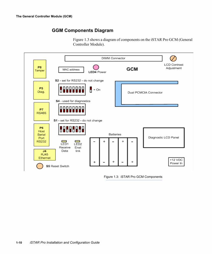
GGM Components Diagram
Figure 1.3 shows a diagram of components on the iSTAR Pro GCM (General Controller Module).
Figure 1.3: iSTAR Pro GCM Components
0 iSTAR Pro Installation and Configuration Guide

Introducing iSTAR Pro
Component Description
The iSTAR Pro GCM contains these major components:
Memory – provides 16 MB flash memory for program storage and 64 MB on-board SDRAM with DIMM socket for memory expansion
PCMCIA Card Slot (Type III) Interface – provides a fully compliant PCMCIA (Type III) standard interface that provides connection to a:
• 10/100BaseT network card• Internal Modem card• Memory card – provides optional memory for event-triggered
backup.
Note: UL has not evaluated the product for use with PCMCIA communication methods.
Note: The iSTAR Pro supports a single card of each type (for example, a network card and a flash memory card), which you can install in either PCMCIA slot. You cannot connect two cards of the same type (for example, two network cards).
Serial Ports – provides an RS-232 external modem port and an RS-232 diagnostic/debug port (DB9, DB25).
Multi-point Port – provides one RS-485 port, used for GCM communication with dual port readers.
Ethernet Port – an RJ-45 jack connector for access to a 10BaseT Ethernet network.
Expansion Connector – a 34-pin connector to the ACM. Input Connector – for low battery, AC power fail, and tamper inputs. Indicators – LEDs that indicate GCM power, Ethernet link, and data
carrier/receive activity. DIP Switches – to set modes or enable/disable various components
These replace jumper functions on previous versions of iSTAR hardware.
Reset button – resets and reboots the iSTAR Pro. Power input – provides 12 VDC input. LCD Display – displays iSTAR Pro diagnostic and status messages. Battery Backup – retains volatile memory (iSTAR Pro data) in the
event of a power failure.
iSTAR Pro Installation and Configuration Guide 1-11

The Access Controller Module (ACM)
1-1
The Access Controller Module (ACM)The iSTAR Pro ACM is a redesigned circuit board assembly that connects to an iSTAR or iSTAR Pro GCM. The ACM contains reader connectors, Class A supervised inputs, relays and output connectors.
Ribbon cables connect the ACM to the GCM and to an (optional) second ACM.
Features
The iSTAR Pro ACM:
Includes features available on previous ACM hardware New features that streamline installation, add functions and improve
reliability
Existing Features
The iSTAR Pro ACM provides these features:
Eight direct connect Wiegand interface ports, for Wiegand Swipe, Proximity, Biometric and Smart Card communication
Four RM direct connect or daisy chain reader Ports, for RM4 communications
Optional I/8 and R/8 modules, for additional inputs and outputs Four additional RM ports (total of 8)
Supports up to 96 inputs and 88 outputs (72 relays) DIP switch support, to replace jumpers and improve ease of board
installation Built-in relay board, to streamline board hardware and improve
reliability
2 iSTAR Pro Installation and Configuration Guide

Introducing iSTAR Pro
ACM Components Diagram
Figure 1.4 shows a diagram of components on the ACM (Access Controller Module).
Figure 1.4: iSTAR Pro ACM
iSTAR Pro Installation and Configuration Guide 1-13

The Access Controller Module (ACM)
1-1
Component Description
The iSTAR Pro ACM contains these major components:
Reader connectors – RS-485 Reader Buses (8 ports) and direct-connect Wiegand™ signaling ports (8 ports)
Supervised inputs – Class A Ribbon Connectors – a 34-pin expansion connector for communication
with the GCM and/or additional expansion card (e.g., another ACM) On-board relays – with relays and output connectors LEDs – indicators for power and system status of communications S2 switch – disables unused Wiegand connections Reset button – reboots the ACM Power input – provides 12 VDC input P34 Jumper – sets voltage for Wiegand readers S3 – configures LED functions on Wiegand readers
ACM Board Layout
Figure 1.5: Photograph of ACM Board
4 iSTAR Pro Installation and Configuration Guide

Introducing iSTAR Pro
ACM CapacitiesThe ACM includes onboard processors that can support up to:
Eight direct-wired Wiegand readers Eight RM Series Readers or RM-4 Modules (by disabling the direct
connect Wiegand ports via switches) Eight output relays and 16 Class A supervised inputs Eight I/8 Modules and eight R/8 Modules
The maximum configuration per iSTAR Pro controller with two ACMs is 16 readers, 16 I/8 Modules, and 16 R/8 Modules. This provides a total of:
195 inputs – 192 on the ACM or on devices connected to it, and 3 on the GCM (dedicated to tamper, power and battery)
176 outputs – on the ACM or on devices connected to it.
Table 1.1 provides a summary of ACM connections and capacities. Table 1.1: ACM Capacities
Reader Type Input Connection Output Connection
RM and/or direct connect Wiegand
16 Inputs on ACM 2 Inputs per RM reader 8 I/8 Modules (8 inputs
each)
max = 96 inputs
8 Outputs on ACM 2 outputs per RM
readera
8 R/8 Modules (8 outputs each)
max = 88 outputs
a. With optional ARM-1 modules, unless RM-4E is used.
iSTAR Pro Installation and Configuration Guide 1-15

Modules that Interface with iSTAR Pro
1-1
Modules that Interface with iSTAR ProTable 1.2 describes modules that interface with the iSTAR Pro,Table 1.2: Modules that Interface with the iSTAR Pro Modules
Module Description
RM-4 and RM-4E The RM-4 and RM-4E are printed circuit boards that provide the hardware interface between either a Wiegand or magnetic signaling reader and apC or iSTAR/iSTAR Pro hardware. The RM-4 and RM-4E also provide the inputs and outputs that communicate between door components and apC or iSTAR hardware.
I/8-CSI The I/8 CSI module expands the number of supervised inputs on the iSTAR Pro. It is an enhanced version of the I/8 module that supports numerous supervised circuit types and EOL resistor values. Different conversion values are selected by DIP switch.
I/8 Module The optional I/8 Module provides eight additional Class A supervised inputs. An I/8 Module can be installed in an appropriate enclosure up to 4000 feet (1212 meters) from the iSTAR Pro controller and wired via an RS-485 bus connection. The I/8 Module power requirement is 125 mA at 12 VDC.
R/8 Module The optional R/8 Module provides eight additional relay outputs. An R/8 Module can be installed in an appropriate enclosure up to 4000 feet (1212 meters) from the iSTAR Pro controller and wired via an RS-485 bus connection. The R/8 Module power requirement is 100 mA at 12 VDC plus 20 mA per active relay (for maximum of 260 mA per module). The relays are rated at 30 V, Resistive 2.0A, Inductive 1.0A.
ARM-1 (Auxiliary Relay Module)a
a. The ARM-1 module has not been evaluated by UL.
The optional ARM-1 reduces wire runs back to the iSTAR Pro. The ARM-1 provides a relay output for a door strike or other equipment located near a standard style RM Series Reader or an RM-4 module. The relays are rated at 30 V, Resistive 2.0A, Inductive 1.0A. The ARM-1 may be installed up to 25 feet (7.6 meters) from the RM-4 module.
Note: RM-4E boards provide on-board relays, and do not require an ARM-1
6 iSTAR Pro Installation and Configuration Guide

Introducing iSTAR Pro
Connecting Security Devices to the ACMThe following types of connections are available on the ACM:
Input – associates a security device with an input on the ACM or add-on module board.
Output – associates an event or input with a relay on the ACM or add-on module board.
Inputs
An input is a software object that associates a security device, such as an alarm switch, with an input on the ACM or input module board. An input reports the state of the switch, which can be active or inactive
A supervised input reports on the status of the wiring between the controller and the switch. If that wiring is cut, the system reports an open circuit. If someone tries to jumper across the wiring (prevent the device from reporting), the system reports a shorted circuit. Supervised inputs can report a total of five conditions to the controller: Short, Open Loop, Line Fault (resistance is outside of expected ranges), Inactive, or Active.
Outputs
An output is a software object that associates an event or input with a relay on the ACM or add-on module. The relay then activates or deactivates devices, such as flood lights and alarm devices.
iSTAR Pro Installation and Configuration Guide 1-17

Connecting Security Devices to the ACM
1-1
Readers
The following RM series readers have been evaluated by UL.
Table 1.3 lists model numbers in the format: RMxx - yyTable 1.3: UL Listed Reader Model Numbers
Where Indicates
RM1 Reader without keypad or LCD
RM2 Reader with keypad; no LCD.
RM2L Reader with keypad and LCD
RM3 Mullion reader. (Does not include RM4 board; mounts on a narrow door frame or mullion.)
yy = 4000 Reader head type Deister, P/N SWH4000-OEM.
yy = MI Reader head type Identec, P/N 1132A.
yy = MP Reader head type Panasonic, P/N ZU-M1121L1 or ZU- M1121LP6B.
yy = PI Reader head type Indala, P/N ASR-SWHS-37, ASR-600, or OMR-705+.
yy = PH Reader head type HID, P/N 4035-ANNOO-51071
yy = W Reader head type Sensor, P/N 3110210.
yy = NH No reader head installed. Specified only with RM2
8 iSTAR Pro Installation and Configuration Guide

Introducing iSTAR Pro
iSTAR ToolsThe following sections describe the configuration and diagnostic tools that are available for iSTAR Pro hardware.
iSTAR Configuration Utility (ICU)
The iSTAR Configuration Utility (ICU) lets you set the initial parameters for iSTAR controllers. The ICU runs on any Windows computer.
The ICU provides the ability to:
Display the status and type of controller Configure IP address and connection information for master and
member controllers Modify identity information for controllers, for example, changing a
member to a master controller Run configuration tools, like Ping and Ping Scan Activate the Monitor controller Run web-based diagnostics Verify host settings Download new firmware to multiple controllers Set the public IP address of the PC running the ICU for firmware
downloads Set the port to use for firmware downloads
Note: The ICU has not been evaluated by UL.
iSTAR Pro Installation and Configuration Guide 1-19

iSTAR Tools
1-2
Configuring Controllers
Use the ICU to configure a controller’s IP addresses, connection type, and identity information.
You can also use the ICU to change a controller’s identity, for example, from master to member, and to modify a controller’s IP addresses.
Caution: At system startup, the C•CURE host downloads IP address information to the master. To ensure proper configuration, the information that you enter in the ICU must match the information that you configure in C•CURE.
Viewing Controller Status
If a controller in the ICU’s subnet is powered on, the utility displays the following information for the controller:
MAC address Name IP address Parent’s IP address (either the host or master controller IP address) Type of controller Connection status
iSTAR Web-Based Diagnostic Utility
The Web-based Diagnostic Utility permits using the Web to view iSTAR Pro status and diagnostics information from any networked computer. The iSTAR web-based diagnostic utility provides:
Password protection Internet access to iSTAR Pro controllers Diagnostic tools for troubleshooting and monitoring system activity
Note: The iSTAR Web-Based Diagnostic Utility has not been evaluated by UL.
0 iSTAR Pro Installation and Configuration Guide

2
iSTAR Pro Topology
This chapter provides an overview of iSTAR Pro topology and configuration options.
iSTAR Pro configurations vary according to site requirements. You must understand iSTAR Pro topology and customer requirements to ensure the correct layout, connections, and configuration of iSTAR Pro components.
In This Chapter
iSTAR Pro Network Topology ............................................................. 2-2Cluster Configuration ........................................................................... 2-5Single Master and Alternate Master Configurations ............................ 2-6Communication Paths ........................................................................... 2-8Maintaining Cluster Communication.................................................. 2-10Choosing Controllers for the Cluster .................................................. 2-13Planning the Communication Path ..................................................... 2-14
iSTAR Pro Installation and Configuration Guide 2-1

iSTAR Pro Network Topology
2-2
iSTAR Pro Network TopologyThe iSTAR Pro supports communications over 10BaseT and/or 100BaseT Ethernet networks using TCP/IP.
Lan and Wan Configurations
The TCP/IP protocol transfers data across a number of networks. Because iSTAR Pro controllers use the TCP/IP protocol for network communications, they can communicate with each other even when controllers are located on different networks separated by other network platforms, as shown in the figure below.
Figure 2.1: Sample iSTAR Pro Network
Gateways and Firewalls
iSTAR Pro configurations provide access to remote C•CURE systems across firewalls and Network Address Translators. This is because the master controller automatically accepts a translated IP address if one is assigned from a remote host, or from an attached Network Address Translator.
iSTAR Pro configurations that accept translated network addresses are usually managed at the remote site. During firewall configuration, TCP/IP ports 1999 and 2001 must be open.
Ethernet
iSTAR Pro Controllers
Hub
LAN 2
iSTAR Pro Controllers
C•CURE System Host
HubEthernet
RouterLAN 1
LAN 3
iSTAR Pro Installation and Configuration Guide

iSTAR Pro Topology
Local Address Management
Although not typically required, System Managers who want to maintain local address management can configure the iSTAR Pro with locked IP addresses. Locked IP addresses retain the iSTAR Pro address that is specified locally, or that is specified by a local DHCP server. When IP addresses are locked, the iSTAR Pro communicates across gateways using only the IP address that you configured. Translated addresses are not accepted.
Before you lock an IP address, you should ensure that it is reliable (that is, not subject to translation) and can be reached from the local network.
The following example shows a locked iSTAR Pro configuration. To configure this cluster, the System Manager in the branch office:
1. Uses PING to check communication to the exposed (translated) address from the Corporate Office.
2. Uses the ICU to configure the master controller and lock the exposed C•CURE address.
3. Uses the ICU to configure the member controllers and lock the local subnet addresses.
Figure 2.2: Locked iSTAR Pro Configuration
Branch Office Corporate Office
iSTARMaster
213.112.60.2
172.54.12.6
C•CURE(locked)
(local)
213.112.60.2(exposed)
Member
Member
168.54.24.5(local)
hostFirewall/
NATGateway
Firewall/NAT
Gateway
iSTAR Pro Installation and Configuration Guide 2-3

iSTAR Pro Network Topology
2-4
IP Management Tools
iSTAR Pro controllers can be configured to accept IP addresses and device names from:
local DHCP (Dynamic Host Configuration Protocol), WINS (Windows Internet Naming Service), or DNS (Domain Name System) servers.
DHCP servers simplify IP management by automatically distributing an IP address to clients when they broadcast to the DHCP server. DHCP servers typically manage a range of IP addresses. WINS and DNS servers complement DHCP address assignment by providing name-to-IP address mapping.
Using NetBIOS and Fully Qualified Domain Names
Configurations where IP addresses are subject to change (for example, leased DHCP addresses) can connect to the C•CURE system using the NetBIOS or fully qualified domain name (FQDN). The configuration must contain a WINS or DNS server, for name/address resolution.
If you are not using DHCP, use the ICU to configure NetBIOS and FQDNs. If you specify a NetBIOS or FQDN name for a C•CURE host, you must also use the ICU to supply the IP addresses of the DNS or WINS server.
iSTAR Pro Installation and Configuration Guide

iSTAR Pro Topology
Cluster ConfigurationiSTAR Pro controllers are organized for network communications into user-defined, logical groups called clusters. Clusters contain one or more controllers. A host can be connected to several clusters.
This section describes the key elements of a cluster.
Master and Member Configuration
Each cluster has one controller that serves as the master, any other controller in the cluster is a cluster member. The master manages all communications between the cluster and a C•CURE host computer.
Cluster members can communicate with each other via the master, over an Ethernet network. Cluster members cannot communicate with each other directly. In Figure 2.3, the diagram on the left shows how cluster member A communicates with the host via the master. The diagram on the right shows how cluster member A communicates with cluster member B via the master.
Figure 2.3: Cluster Member Communications
Host
Hub
1
4
3
2
MasterCluster Member A
Cluster Member B
Ethernet
Network
143
2
Cluster Member BCluster Member A
Master
Host
Cluster Member A to Host Cluster Member A to Member B
iSTAR Pro Installation and Configuration Guide 2-5

Single Master and Alternate Master Configurations
2-6
Single Master and Alternate Master ConfigurationsTo ensure continuous connection, the iSTAR Pro cluster can communicate with C•CURE using:
A primary and optional secondary path, configured on a single master controller
A primary path on a master controller, and an optional secondary path on an alternate controller.
Figure 2.4 shows primary and secondary communications using a single master (left) and alternate master (right).
Figure 2.4: Single and Alternate Master Configurations
Master Alternate Master
Primary Primary
Host
Master
Cluster Cluster
Single Master Configuration
Host
Alternate Master Configuration
Secondary Secondary
iSTAR Pro Installation and Configuration Guide

iSTAR Pro Topology
Single Master Configurations
The following table shows the configuration options for clusters that provide communication using a single master controller.
Alternate Master Configurations
Clusters that use an alternate master must use the 10BaseT (onboard) Ethernet connections for both master and alternate. Mixed connections (i.e., 100BaseT primary, 10BaseT secondary) are not supported.
Table 2.1: Supported Communication Paths for Master Controllers
Primary Secondary
Onboard (10BaseT) Ethernet No connection
Onboard (10BaseT) Ethernet PCMCIA (10/100BaseT) Ethernet
Onboard (10BaseT) Ethernet Dial-up
Onboard (10BaseT) Ethernet Serial
PCMCIA (10/100BaseT) Ethernet No connection
PCMCIA (10/100BaseT) Ethernet Onboard (10BaseT) Ethernet
Serial No connection
Dial-up No connection
iSTAR Pro Installation and Configuration Guide 2-7

Communication Paths
2-8
Communication PathsThe master controller connects to the host over a primary communication path. An optional secondary path can be configured to ensure continuous host communication.
The Primary Communications Path
The primary path is the first communication path that controllers use to establish communications with the host. The master is the only controller in a cluster that passes messages between the host and cluster members. Cluster members do not communicate with the host directly; they communicate with the host through the master. Connections are established in the following bottom-to-top order:
Cluster members are responsible for establishing connections with the master.
The master is responsible for establishing a connection with the host.
The Connection type is how the master connects to the host. Allowable types include network (10BaseT/100BaseT), dial-up, and serial connections. Cluster members are connected to the master only via a network connection.
Figure 2.5 shows the primary path for cluster member A. In this case, the master/host connection type is network.
Figure 2.5: The Primary Path
Host
Hub
1
4
3
2
Master Cluster Member B
Ethernet
Network
Cluster Member A
iSTAR Pro Installation and Configuration Guide

iSTAR Pro Topology
The Secondary Communications Path
A secondary path is the host communications path that is used by a cluster if a communications failure occurs on the primary path. Table 2.1 on page 2-7 shows the configuration options for primary and secondary communications.
Figure 2.6 shows two examples of secondary communications:
A secondary path on a single master configuration using two network connections (left).
A secondary path on the alternate master (right). Configurations that use an alternate master must connect to the host over 10BaseT Ethernet on both primary and secondary paths.
Figure 2.6: The Secondary Path
Single Master Configuration
Host
Master
Alternate Master Configuration
MasterAlternate Master
Host
MemberMember
Network
Member
Network
iSTAR Pro Installation and Configuration Guide 2-9

Maintaining Cluster Communication
2-1
Maintaining Cluster CommunicationMaintaining cluster communications involves establishing and maintaining connections via the primary or (optional) secondary communication path. If the primary connection is lost, the secondary communication path is used to re-establish cluster communications.
Single Master Configurations
If a configuration with a single master loses its connection with the host (Figure 2.7):
Cluster members continue to communicate with the master. The master continues to pass cluster members’ messages to the host. The master uses the secondary path to communicate with the host.
For example, if the secondary path is an alternate network connection between the master and host, the master uses the alternate network to communicate with the host.
Figure 2.7: Communication Failure with Single Master Configuration
Host
Master
Network Failure
MemberMember
0 iSTAR Pro Installation and Configuration Guide
iSTAR Pro Topology
Alternate Master Configurations
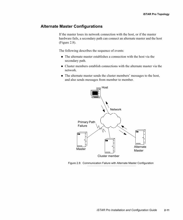
If the master loses its network connection with the host, or if the master hardware fails, a secondary path can connect an alternate master and the host (Figure 2.8).
The following describes the sequence of events:
The alternate master establishes a connection with the host via the secondary path.
Cluster members establish connections with the alternate master via the network.
The alternate master sends the cluster members’ messages to the host, and also sends messages from member to member.
Figure 2.8: Communication Failure with Alternate Master Configuration
Host
Master
Primary Path Failure
Cluster member
Alternate Master
Network
iSTAR Pro Installation and Configuration Guide 2-11

Maintaining Cluster Communication
2-1
Communication Between Members and Master
If a cluster member loses its connection with the master and the secondary path is a connection between the host and an alternate master (Figure 2.9):
The cluster member connects directly to the alternate master. The alternate master passes the cluster members’ messages to the host.
Figure 2.9: Re-establishing Connections During Communication Failure
Host
Hub
Master
Network
Primary Pathfailure
1
4
3
2
Cluster member
Alternate Master
2 iSTAR Pro Installation and Configuration Guide

iSTAR Pro Topology
Choosing Controllers for the ClusterFollow these guidelines when adding controllers to a cluster.
A controller must be assigned to a cluster before the controller can communicate with the host, master, or other controllers. Use the “Cluster” window in the C•CURE Administration application to add controllers to a cluster. When added to a cluster, the controller becomes a cluster member.
One controller can comprise a cluster. You can configure a controller as its own cluster by configuring a cluster that includes only the controller and specifying that controller as the master.
A cluster member communicates with other cluster members through the master.
A cluster communicates with the C•CURE host via the cluster’s primary or secondary path.
A cluster communicates with other clusters and with apC panels via the C•CURE host.
A cluster can communicate with the C•CURE server across a WAN. You can configure clusters that are spread across WAN topologies.
iSTAR Pro Installation and Configuration Guide 2-13

Planning the Communication Path
2-1
Planning the Communication PathThis section includes guidelines and procedures for configuring primary and secondary communication paths.
Planning Primary Communications
Configuring a primary communication path involves:
Specifying a master for the cluster Specifying one of the following communications methods between the
master and the C•CURE host:• Onboard Ethernet (default)• PCMCIA Ethernet• RAS direct serial • RAS (internal or external) modem
Specifying connection parameters for establishing and maintaining the primary path
Primary Communication Guidelines
Follow these guidelines when configuring a primary path:
Every cluster must have a master. Only one master is allowed per cluster (although an alternate master
may be designated for secondary communications). If a cluster contains only one controller, that controller is the master. Any controller in a cluster can be designated as the master. Masters can connect to the C•CURE host via a network, serial, or
modem connection.
4 iSTAR Pro Installation and Configuration Guide

iSTAR Pro Topology
Planning Secondary Communications
Configuring a secondary communications path involves:
Specifying a controller that is responsible for secondary communications with the C•CURE host when a communications failure occurs on the primary path. In almost all cases, this is the same controller that provides the primary path.
Specifying the connection type. Refer to Table 2.1 on page 2-7 for information about configuration options.
iSTAR Pro Installation and Configuration Guide 2-15

Planning the Communication Path
2-1
6 iSTAR Pro Installation and Configuration Guide
3
Site Requirements
This chapter provides information on site planning for iSTAR Pro hardware.
In This Chapter
Pre-Installation...................................................................................... 3-2Installation Requirements ..................................................................... 3-4
iSTAR Pro Installation and Configuration Guide 3-1
Pre-Installation
3-2
Pre-InstallationPre-installation involves:
Checking equipment (hardware, software, power supply and wiring) Checking power, wiring, equipment clearances and code compliance at
the site Ensuring proper tools are available
Equipment Check
Basic installations require the following equipment: hardware, software, power supply, readers, inputs/outputs, and wiring. Primary or secondary communications may also require a modem.
The iSTAR Pro hardware does not include mounting hardware for an installation. Mounting hardware depends upon the site and must be approved by a structural engineer or other certified professional. Software House recommends anchoring systems capable of sustaining a 75 lb. (34.1 kg) load.
Verify that the contents of the boxes shipped match the packing lists. Contact Software House if any items are missing or damaged.
Site Check
Ensure the following:
The mounting site is ready. The upper mounting screws should be 14.25" (36.195 cm) center to center, the bottom mounting holes are 21.35" (54.229 cm) below the upper mount holes.
The site has been approved and that all wiring complies with UL requirements and other codes as appropriate.
All preliminary site work is complete. An appropriate power supply is accessible. The site is clean and free of dust or other contaminants.
iSTAR Pro Installation and Configuration Guide

Site Requirements
The wiring for each reader conforms to voltage requirements.A standard RM Series Reader or RM-4 board requires at least 7.5 volts to operate properly. An RM-4E board requires at least 11 volts to operate properly. While the iSTAR Pro supplies 12 volts at its connectors, the amount of voltage that reaches the reader is impacted by the:
• Number of devices on the bus• Current draw of each device • Distance between devices • Distance between the device and the iSTAR Pro • Wire gauge that connects the devices
To determine the maximum distance of an RM reader from the iSTAR Pro, you must calculate the voltage that reaches each reader. If the voltage is insufficient, you must shorten the wire length, use a heavier wire, or add a local power supply.
Tools
iSTAR Pro installation requires:
Standard tool kit Security screwdriver (contact Software House) 3/32" (2.4 mm) screwdriver (supplied with iSTAR) 5/16" (#10) nut driver Wire strippers Anti-static equipment: floor mat, counter top mat, and wrist strap Small needlenose pliers
iSTAR Pro Installation and Configuration Guide 3-3

Installation Requirements
3-4
Installation RequirementsThis section describes iSTAR Pro hardware, software, environmental and configuration requirements.
Host System Requirements
The iSTAR Pro requires a host computer configured as a C•CURE system server/host meeting all the hardware and software requirements for servers described in the C•CURE Installation Guide.
iSTAR Pro Cabinet Requirements
iSTAR Pro hardware is mounted in the same cabinet as previous versions of iSTAR hardware.
The iSTAR Pro cabinet conforms to the following specifications:
Environmental Requirements
Table 3.2 shows iSTAR Pro environmental requirements.
Table 3.1: Cabinet Assembly Specifications
Item Specification
Weight 23 lbs (10.4 kg)
Height 24" (60.9 cm)
Width 16.5" (41.9 cm)
Depth 4.5" (11.4 cm)
Table 3.2: Environmental Requirements
Status Range
Operation 32° F (0° C) to 120° F (48.9° C)
Storage 4° F (-20° C) to 158° F (70° C)
iSTAR Pro Installation and Configuration Guide

Site Requirements
Host Communication Baud Rate Requirements
The iSTAR Pro-to-host communication default baud rate is set at 57,600 (bps) for dialup or direct-connect serial connections. The diagnostic port uses a baud rate of 115,200 (bps).
Modem and Phone Line Requirements
Note: UL has not evaluated the iSTAR Pro for use with these communications methods.
When using a modem for primary or secondary communications, Software House recommends a dedicated phone line (to reduce potential communication delays) and modem connection via the PCMCIA port.
The following are qualified PCMCIA modems:
Diamond SupraMax 56K PCMCIA ModemSM56PCM SWH p/n STAR-PCC-MDM, Zoom Dual-mode Zoom PC Card 56K Fax/Modem EXP ThinFax 56L Hayes ACCURA 56K/V.90 PC card
You can also connect to the host using an external modem. The 3Com US Robotics Faxmodem Model 5686-03 has been qualified by Software House. The recommended distance is 15 feet (4.5 meters) between the iSTAR Pro and the external modem.
The host side can use any Windows supported modem.
Power Requirements
The iSTAR power requirements depend on the type of power supply you are using.
If the iSTAR cabinet contains a Lien Industries power supply (Model SP85W1P-289C), the iSTAR Pro input rating is 100 - 240 VAC, 2.3A max, 47-63 Hz. Also, the system current draw is 2.3A@100VAC and 1.1A max@240VAC, 47-63Hz. The maximum current draw is dependent on the AC input line voltage. Output is 12V@5A.
iSTAR Pro Installation and Configuration Guide 3-5

Installation Requirements
3-6
If the iSTAR cabinet contains a Wall Industries (Sinpro) power supply (SBU120-105), the iSTAR Pro input rating is 100 - 240 VAC, 1.7A max, 47-63 Hz. Also, the system current draw is 1.7A@100VAC and 0.8A max@240VAC, 47-63Hz. The maximum current draw is dependent on the AC input line voltage. Output is 12V@5A.
To ensure adequate power, you must calculate the total power requirements of the iSTAR Pro and related hardware.
1. Add the total current power for components in the system (modules, relays, optional modules, readers, wire resistance, etc.).
2. If the maximum power consumption exceeds the output of the iSTAR Pro power supply, connect an additional power supply to the system.
Use Tables 3.3 through 3.8 to compute the current draw of components attached to the iSTAR Pro.
With a Lien Industries power supply, the iSTAR Pro can deliver 12VDC at 5.0 amps.
With a Wall Industries (Sinpro) power supply, the iSTAR Pro can deliver 12VDC at 5.0 amps.
The optional power battery backup known as the Advanced Power System (apS) can supply a maximum of 3.75 A@12VDC to the iSTAR controller.
iSTAR Pro Components and Boards
Table 3.3 shows the power requirements of iSTAR Pro components and attached boards.
Table 3.3: Component and Board Power Requirements
Component/Board Current Draw at 12VDC
iSTAR Pro GCM board 290mA max
iSTAR Pro ACM board 150 mA - no load
RM-4 boarda 75 mA - no load
RM-4E boardb 240 mA - no load
I/8 boardc 150 mA - no load
iSTAR Pro Installation and Configuration Guide

Site Requirements
iSTAR Pro Reader Ports
Table 3.4 shows the maximum ratings for ACM Wiegand reader ports.
Table 3.5 shows maximum rating for RM ports.
R/8 boardc 150 mA - no active relays.Add 17 mA for each active relay
a. The RM-4 board has only been evaluated by UL for use within the RM readerenclosure.
b. The RM-4E board has only been evaluated by UL for use within theRM-DCM-2 enclosure.
c. These boards have not been evaluated by UL for use with the iSTAR Pro.
Table 3.4: Wiegand Port Rating
Port Rating
Reader output control (red, green, yellow,
beeper)
4.0 v to 5.25 v, 20 mA maximum
Reader input lines (D0, D1)
Low level <0.8 vHigh level from 4.0 v to 5.25 v
Reader output voltage 5 VDC or +12 VDC (jumper selectable)
Reader current 350 mA max per reader, not to exceed 2.5 A for Wiegand and RM readers
Table 3.5: RM Port Rating
Port Rating
Reader output voltage +12 VDC
Reader current 350 mA max per port, not to exceed 2.5 A for Wiegand and
RM readers
Table 3.3: Component and Board Power Requirements
Component/Board Current Draw at 12VDC
iSTAR Pro Installation and Configuration Guide 3-7

Installation Requirements
3-8
Software House Readers
Table 3.6 shows power requirements for Software House readers.
Table 3.6: Software House Reader Power Requirements
Reader Model Numbers Current Draw at 12VDC
RM with mag stripe RM1-MP, RM2-MP 80 mA
RM with mag stripe and LCD
RM2L-MP 180 mA
RM with mag stripe mullion
RM3-MP 80 mA
RM with Indala proximity RM1-PI, RM1-PI/Ca, RM2-PI, RM2-PI/Ca
80 mA
RM with Indala proximity and LCD
RM2L-PI 180 mA
RM with HID proximity RM1-PH, RM2-PH 135 mA (avg.)250 mA (peak)
RM with HID proximity and LCD
RM2L-PH 235 mA (avg.)250 mA (peak)
RM with HID proximity mullion
RM3-PH 135 ma (avg.)250 mA (peak)
RM with Wiegand RM1-W, RM2-Wa 80 mA
RM with Wiegand and LCD RM2L-Wa 180 mA
RM with Wiegand mullion RM3-Wa 80 mA
Multi-Technology Contactless Reader
SWH-4100a, SWH-4200a, SWH-2100a, SWH-5000a, SWH-5100a, SWH-5200a, SWH-1000a, SWH-1100a, SWH-3000a, SWH-3100a
125 mA
Auxiliary Relay Module ARM-1a 17 mA (relay active)
iSTAR Pro Installation and Configuration Guide

Site Requirements
RM with HID iClass RM1-iC, RM2-iC 135 ma (avg.)250 mA (peak)
RM with HID iClass and LCD
RM2L-iC 235 mA (avg.)350 mA (peak)
a. These models have not been evaluated by UL.
Table 3.6: Software House Reader Power Requirements (Continued)
Reader Model Numbers Current Draw at 12VDC
iSTAR Pro Installation and Configuration Guide 3-9

Installation Requirements
3-1
Third Party Readers
Table 3.7 shows power requirements for third-party readers.
Note: Not all readers have been evaluated by UL. For a complete list of approved readers, call Software House customer support.
Modem and Ethernet
Note: The PCMCIA protocol has not been evaluated by UL.
Table 3.8 shows power requirements for modem and Ethernet components.
Table 3.7: Third Party Reader Power Requirements
Reader Current Draw at 12VDC
Indala ASR-101, 103, 105, 110, 112 150 mA
Indala PR5, 10, 12 130 mA
Indala ASR-120, 122 350 mA
Sensor Eng WR1, WR2 30 mA
HID MiniProx 60 mA
HID ProxPro 100 mA
HID MaxiProx 200 mA
Barantec 150 mA
HID iCLASS 100 mA
Integrated Engineering Smart ID 50 mA (avg)160 mA (peak)
Table 3.8: Modem and Ethernet Power Requirements
PCMCIA Board Current Draw at 12VDC
PCMCIA modems 220 mA typically
PCMCIA Ethernet 260 mA typically
0 iSTAR Pro Installation and Configuration Guide

Site Requirements
Wyreless Products
The Wyreless Panel Interface Module (PIM) and Access Point Modules (WAPMs) provide wireless door monitoring on a C•CURE system. Only the PIM is directly connected via RS-485 to the iSTAR Pro controller.
Power requirements for the Wyreless PIM-OTD-485 are 300mA @ 12VDC.
Note: Wyreless products have not been evaluated by UL for use with the iSTAR Pro.
Ethernet Requirements
The iSTAR Pro Ethernet options include:
Onboard Ethernet port – supports 10BaseT Ethernet connection to a Socket Low Power 10 BaseT Ethernet connector (Mfg. part number EA0911-336).
PCMCIA port – supports 10/100BaseT Ethernet connection (one slot only).
Recommended cards include:
Note: The PCMCIA protocol has not been evaluated by UL.
Note: The iSTAR Pro has not been evaluated by UL for operation over WAN topologies.
Table 3.9: Supported NICs
10/100 Base T Ethernet Part No.
Software House STAR-PCC-NIC
SMC Networks EZ Card 10/100 PC Card SMC8041TX
iSTAR Pro Installation and Configuration Guide 3-11

Installation Requirements
3-1
Wiring Requirements
Table 3.10 shows general wiring requirements for an iSTAR Pro and its components.
Table 3.10: Equipment Wiring Specifications
Signal From To Belden # Gauge # Prs Shielded Max Length
RS-232 Comm,5 wire
Host iSTAR GCM 8303 22 3 Yes 49.2 ft.(15 m)
RS-485 Comm, two wire
iSTAR ACM
RM &I/O Modules
9841 24 1 Yes 4000 ft.(1212 m)
Modem DB9 or DB25, 5 wire
iSTAR GCM
Modema 8303 22 3 Yes 15 ft. (4.5 m)
Power iSTAR ACM
RM &I/O Modules
8442/8461 22/18 1 No Variesb
RJ45-Ethernet iSTAR GCM
Hub, Host N/A Cat 5 or
better
2 N/A max 328 ft. (100 m)min. 8 ft. (2.4 m)
Control iSTAR ACM to ARM-1
Strike 8461 18 1 No 25 ft (7.6 m)
SupervisedInputc
iSTAR ACM
Input 8442/8461 22/18 1 No 2000 ft.(606 m)
Request-to-exit Reader or RM-4
module
Switch 8442/8461 22/18 1 No 2000 ft.(606 m)
Door contact Reader or RM-4
module
Contact 8442/8461 22/18 1 No 2000 ft.(606 m)
Relay Control RM Reader or RM-4 module
ARM-1 9462 22 1 Yes 25 ft.(7.6 m)
2 iSTAR Pro Installation and Configuration Guide

Site Requirements
ReaderData
Pro ACM,eX GCM,
RM-4,RM-4E,WPSC
Wiegand read head
9942
9260
Alpha wire
5386C
22
20
18
3 Yes 200 ft.(60.96 m)
300 ft.(91.4 m)
500 ft.(152.4 m)
ReaderData
RM-4 orRM-4E
Magnetic read head
22 No 10 ft.
a. Software House requires the use of qualified modems. b. Check wire lengths and voltage drop.c. To comply with UL requirements, use shielded, minimum 22 AWG stranded, twisted pair cable for
monitor points, DSMs, and REXs. Use Belden 9462 or equivalent.
Table 3.10: Equipment Wiring Specifications (Continued)
Signal From To Belden # Gauge # Prs Shielded Max Length
iSTAR Pro Installation and Configuration Guide 3-13

Installation Requirements
3-1
GCM / ACM Connectors (Different suppliers)
Caution: Tolerance issues may cause loose connections in the field when connectors from different suppliers are mixed, leading to intermittent problems that are difficult to troubleshoot.
Figure 3-1: Typical Connector
A good field test is to put the connector on a loose RM, I8, or R8 board and see if you can lift the board, by gripping only the connector. If the connector slips off, or seems loose, replace with another one.
If you encounter a loose connector, replace it with a good one. Contact Technical Support for replacements.
4 iSTAR Pro Installation and Configuration Guide

Site Requirements
Avoiding Card Misreads
When the cable length to the read head nears the limit of 200’, 300’, or 500’, depending on the wire gauge, the circuit is more susceptible to signal degradation which may result in card misreads.
Card misreads in an access control system can be caused by various conditions, including:
Configuration errors, such as wrong number of bits in the card format or format not assigned to reader.
Parity errors from individual cards. Multiple cards in the same proximity reader field. Signal degradation between the Wiegand read head and control panel or
module.
Signal degradation can be caused by RF noise or loss of signal integrity.
RF noise can be induced from outside sources including, but not limited to, power sources, fluorescent lighting, elevators, and AC motors. To reduce RF noise, adhere to good shielding practices.
Signal integrity can be compromised by cable length and /or cable characteristics such as gauge, impedance, inductance, and capacitance. Refer to Table 3.10 on page 3-12 when connecting read heads.
Read heads can be connected to the following components:
RM-4 RM-4E iSTAR Classic/Pro ACM iSTAR eX GCM apC - WPSC
iSTAR Pro Installation and Configuration Guide 3-15

Installation Requirements
3-1
RS-232 Requirements
You can connect the iSTAR Pro to the host by connecting the RS-232 port (P6) on the GCM to a DB9 or DB25 connector. The maximum recommended distance between the iSTAR controller and the host is 50 ft (15.2 m).
The RS-232 connection requires jumping two pins at the host end of the connector. Refer to “Connecting to the Host using RS-232,” on page 4-12 for additional information about RS-232 wiring.
Grounding Requirements
Ground requirements are as follows:
Ensure that the iSTAR Pro controller is properly connected to an earth ground at the ground stud near the AC input wiring.
Ensure that the shield wires are grounded at one end of the cable to the nearest earth/ground connection.
When disconnecting wiring, disconnect ground wires last (to provide maximum protection to the equipment and personnel).
6 iSTAR Pro Installation and Configuration Guide

4
This chapter provides information about installing iSTAR Pro hardware.
In This Chapter
Installation Overview............................................................................ 4-2Mounting the Enclosure........................................................................ 4-4Installing Flash Memory....................................................................... 4-7Installing Batteries ................................................................................ 4-8Connecting to the Host ....................................................................... 4-10Low Battery, Power Fail and Tamper Inputs...................................... 4-19Connecting AC Power ........................................................................ 4-21Installing modular boards ................................................................... 4-22Installing a modular GCM .................................................................. 4-22Installing the first modular ACM........................................................ 4-23Installing the second modular ACM................................................... 4-24Wiring Inputs, Outputs, and Readers.................................................. 4-25
HardwareInstallation
iSTAR Pro Installation and Configuration Guide 4-1

Installation Overview
4-2
Installation OverviewThe following equipment is required:
Antistatic floor mat, tabletop mat, and wrist strap 3/32" (2.4 mm) screwdriver (supplied with the iSTAR Pro), the primary
tool needed to secure wires into all the input, output, and reader connectors
Security screwdriver Small needlenose pliers 5/16" (#10) nut driver (suggested for securing shield wires to a ground
stud)
Procedure Overview
Table 4.1 provides an overview of the iSTAR Pro installation procedure.
Table 4.1: Installation Overview
Step Procedure Additional Information
1 Unpack and mount the iSTAR Pro enclosure.
Refer to “Mounting the Enclosure,” on page 4-4
2 Install PCMCIA cards, if required.
Refer to: “Installing Flash Memory,” on
page 4-7 “To connect to the PCMCIA
port,” on page 4-12 “Connecting a PCMCIA
Modem,” on page 4-16
3 Install batteries. Refer to “Installing Batteries,” on page 4-8
4 Connect to the host. Refer to: “Connecting to the Host via the
Network,” on page 4-10 “Connecting to the Host using
RS-232,” on page 4-12 “Connecting to the Host via
Modem,” on page 4-15
iSTAR Pro Installation and Configuration Guide

Hardware Installation
5 Attach low battery, power fail, and tamper inputs.
Refer to “Low Battery, Power Fail and Tamper Inputs,” on page 4-19
6 Configure ACM inputs and outputs.
7 Connect I/8 and R/8 boards, if required.
8 Connect Wiegand readers, if required.a
9 Connect AC power and optional power supply unit, if required.
Refer to:“Connecting AC Power,” on page 4-21
a.
Table 4.1: Installation Overview (Continued)
Step Procedure Additional Information
iSTAR Pro Installation and Configuration Guide 4-3

Mounting the Enclosure
4-4
Mounting the Enclosure You can mount any combination of iSTAR and iSTAR Pro GCM and ACM components inside the standard metal enclosure.
Static Electricity
Caution: Observe standard precautions regarding static electricity when handling hardware components.
Before handling any internal components, discharge static electricity by touching a grounded surface.
Wear a grounding wrist strap and stand on a grounded static protection mat.
Limit movement during installation to reduce static buildup.
To mount the controller
1. Verify that the upper mounting screws (or equivalent) are in place on the mounting site.
2. Carefully unpack the components. Observe static electricity precautions.
3. Open the enclosure door.
4. Carefully lift the door off the hinges and place it on a padded surface.
5. Align the mounting keyhole slots at the upper back of the enclosure with the two upper mounting screws and lower the enclosure into position.
6. Install the two bottom mounting screws.
iSTAR Pro Installation and Configuration Guide

Hardware Installation
Figure 4.1: Controller (Door Open)
iSTAR Pro
Status LED
Door Lock
iSTAR Pro Controller
Door
Hinge
Door
Door Lock
iSTAR Pro Installation and Configuration Guide 4-5

Mounting the Enclosure
4-6
Figure 4.2: Controller with Door Removed (2 ACMs Mounted)
7. Remove the appropriate knockouts for all the wiring inputs and outputs.
8. Attach conduit couplings to the knockout openings as needed to comply with code.
Ground Stud (6-32) For Shield Wire, 1 By Each Knockout
100-240 VAC Input Terminal Block
12 VDC Output Power Supply
1.12" (28.448 mm) Triple Knockouts (2 Top, 2 Each Side,1 Bottom)Cabinet/Enclosure
General Controller Module (GCM)
Access Control Module(ACM)
0.87"(22.098 mm) Single Knockouts (2 Each Side)
Ground
Keyhole Mounting Slot (2)
Lower Mounting Hole (2)
Identification Label
Tamper Switch
iSTAR Pro Installation and Configuration Guide

Hardware Installation
Installing Flash MemoryYou can use the PCMCIA port on the iSTAR Pro to plug in an optional flash memory card. The flash memory card provides backup storage for systems that use event triggered backup. Refer to the Advanced User’s Guide for details about event-triggered backup.
Note: The Flash memory feature has not been evaluated by UL.
To add flash memory cards
1. Check the flash memory card to ensure that it is the same size or bigger than iSTAR Pro DRAM memory. DRAM is used to store iSTAR data. Your flash memory card must the the same size or bigger to save all iSTAR data.
2. Insert the flash memory card into the PCMCIA slot.
iSTAR Pro Installation and Configuration Guide 4-7

Installing Batteries
4-8
Installing BatteriesUse NiMH (Nickel Metal Hydride) batteries - AA size. Minimum 1800 mAH hours.
The batteries provide 24 hour backup, and require 24 hour charge time.
The cells should be replaced as follows:
Every year After a complete discharge
NOTE The iSTAR Pro Battery Charger test does not indicate battery condition, it only tests the charger circuit.
NOTE The batteries provide power to retain the volatile memory (clearances, activity, etc.) data in the event of a power failure. The batteries do not supply enough power for iSTAR Pro normal operations.
Caution: Risk of explosion if battery is replaced by an incorrect type. Dispose of used batteries according to the instructions.
iSTAR Pro batteries are packaged separately and should be installed in the backup battery sockets at the bottom of the GCM.
The unit is stored and shipped with the batteries disconnected so they will not be drained while in storage. Connect the batteries as shown in the GCM diagram “Installing Backup Batteries,” on page 4-9.
If the batteries are installed with the power off, the reset switch (S5) must be pressed after power is applied.
It is acceptable to install the batteries with the power on. However, if the batteries are installed with the power on, you do not need to press the reset switch.
iSTAR Pro Installation and Configuration Guide

Hardware Installation
Install the batteries in the backup battery slots at the bottom of the GCM. Figure 4.3 shows the installation slots and polarity for iSTAR Pro batteries.
Figure 4.3: Installing Backup Batteries
Backup Battery Slots
iSTAR Pro Installation and Configuration Guide 4-9

Connecting to the Host
4-1
Connecting to the HostYou can connect the iSTAR Pro GCM to the host using:
Network connections – connect to the GCM onboard (10BaseT) port or the GCM PCMCIA (10/100BaseT) port.
Direct RS-232 connections – connect to the GCM P6 connector. Modem connections – connect a modem card to the GCM PCMCIA port
(recommended) or connect the GCM P6 connector to a qualified external modem.
Note: Modem connections to the iSTAR Pro have not been evaluated by UL.
Configurations that communicate from the iSTAR Pro to the host using serial or modem connections must also install Remote Access Service (RAS) on the C•CURE 800/8000 host.
Note: The C•CURE 9000 does not support serial or modem connections using RAS.
Primary and Secondary Connections
One iSTAR Pro controller is always designated as master, and provides the primary communication path to the host. A secondary path can be configured on the same master or on an alternate master.
This section provides instructions for connecting the iSTAR Pro to the host. Refer to Table 2.1 on page 2-7 for the list of primary and secondary configurations recommended by Software House.
Connecting to the Host via the Network
The iSTAR Pro controller includes:
Onboard (10BaseT) Ethernet connection (standard)
0 iSTAR Pro Installation and Configuration Guide

Hardware Installation
PCMCIA (10/100BaseT) Ethernet connection (optional)
Note: PCMCIA connections to the iSTAR Pro have not been evaluated by UL.
Note: iSTAR Pro supports a single PCMCIA Ethernet connection which you can configure from either of the two PCMCIA ports on the GCM. You can use the empty port to install a compact flash memory card or internal modem card, if desired.
To connect to a 10BaseT network
1. Route the Ethernet wiring into the controller through the closest knockout/conduit to the port.
2. Plug the RJ-45 connector into the J4 port on the GCM (Figure 3).
Figure 4.4: Connecting Ethernet
3. Place a ferrite clamp (PN 0444164181) on the Ethernet cable inside the chassis (Figure 4.5).
iSTAR Pro Installation and Configuration Guide 4-11

Connecting to the Host
4-1
Figure 4.5: Ethernet Ferrite
To connect to the PCMCIA port
1. Insert the PCMCIA card into the iSTAR Pro port (see Figure 3).
2. Connect the Ethernet cable to the card and route the cable through the closest knockout/conduit at the side or top of the box.
3. Press the reset button to reboot the controller.
Connecting to the Host using RS-232
Configurations that communicate from the iSTAR Pro to the host using serial or modem connections must also install Remote Access Service (RAS) on the C•CURE 800/8000 host.
Note: The C•CURE 9000 does not support serial or modem connections using RAS.
2 iSTAR Pro Installation and Configuration Guide

Hardware Installation
To connect the controller to the host via RS-232 (DTE to DTE)
1. Route the host RS-232 wiring into the controller through the closest conduit/knockout to the port.
2. If needed, strip the end of the wires enough (1/4") to permit insertion into a connector.
3. Use the 3/32" (2.5 mm) screwdriver to loosen the screws just enough to insert the wires.
4. Detach the P6 connector from the board.
5. Connect the wires to the P6 connector (Figure 4.6).
Figure 4.6: P6 Connections
6. Tighten the screws.
Screw
P6 Five Pin Connector (Top View)
Insert Wires Into Openings
P4 Five Pin Connector(Side View)
Pin 3
Pin 2
RXD-
Gnd
TXD-CTS RTS
15
Pin 1
Pin 4
Pin 5
iSTAR Pro Installation and Configuration Guide 4-13
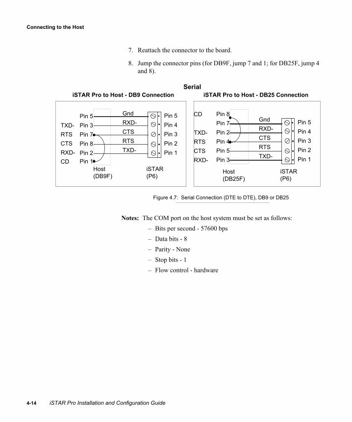
Connecting to the Host
4-1
7. Reattach the connector to the board.
8. Jump the connector pins (for DB9F, jump 7 and 1; for DB25F, jump 4 and 8).
Figure 4.7: Serial Connection (DTE to DTE), DB9 or DB25
Notes: The COM port on the host system must be set as follows:– Bits per second - 57600 bps– Data bits - 8– Parity - None– Stop bits - 1– Flow control - hardware
Host (DB9F)
iSTAR Pro to Host - DB9 Connection
iSTAR (P6)
Host (DB25F)
iSTAR Pro to Host - DB25 Connection
iSTAR (P6)
Pin 5Pin 4Pin 3Pin 2Pin 1
GndRXD-CTSRTSTXD-
Pin 5Pin 4Pin 3Pin 2Pin 1
GndRXD-CTSRTSTXD-
Pin 5Pin 3Pin 7Pin 8Pin 2Pin 1
TXD-RTSCTSRXD-CD
Pin 8Pin 7Pin 2Pin 4Pin 5Pin 3
CD
TXD-RTSCTSRXD-
Serial
4 iSTAR Pro Installation and Configuration Guide

Hardware Installation
9. Locate the S1 DIP switch and set each switch as shown in Figure 4.8.
Figure 4.8: S1 Switch Settings
Connecting to the Host via Modem
You can connect to the host using a:
PCMCIA internal modem card, or External modem
Note: Use of PCMCIA modem cards with the iSTAR Pro has not been evaluated by UL.
Configurations that communicate from the iSTAR Pro to the host using serial or modem connections must also install Remote Access Service (RAS) on the C•CURE 800/8000 host.
Note: The C•CURE 9000 does not support serial or modem connections using RAS.
S1-1 OnS1-2 OffS1-3 OnS1-4 OffS1-5 OnS1-6 OffS1-7 OnS1-8 Off
iSTAR Pro Installation and Configuration Guide 4-15

Connecting to the Host
4-1
Connecting a PCMCIA Modem
To connect via PCMCIA card modem
1. Insert the PCMCIA card into the iSTAR Pro slot (see Figure 4.9).
Figure 4.9: Connecting Modems
2. Attach the telephone cable to the card and route the cable through the closest knockout/conduit at the side or top of the box.
3. Press the reset button to reboot the controller.
Connecting an External Modem
Note: Use of dialup modem connections with the iSTAR Pro has not been evaluated by UL.
6 iSTAR Pro Installation and Configuration Guide

Hardware Installation
To connect the external modem
1. Install the external modem per manufacturer’s instructions.
2. Set the modem DIP switches according to manufacturer’s instructions.
3. Route the modem wiring into the controller through the closest conduit/knockout.
4. If needed, strip the end of the wires enough (1/4") to permit insertion into a connector.
5. Use the 3/32" (2.5mm) screwdriver to loosen the screws just enough to insert the wires.
6. Detach the P6 connector from the board.
7. Connect the wires to the P6 connector (Figure 4.10).
Figure 4.10: P6 Connections
8. Tighten the screws.
9. Re-attach the connector to the board.
10. Verify that the modem pin-outs are as shown in Figure 4.11.
P6 Five Pin Connector (Front View)
Pin 1 (TX-)
Pin 3 (CTS)
Pin 4 (RX-)
Pin 2 (RTS)
Pin 5 (Gnd)
iSTAR Pro Installation and Configuration Guide 4-17

Connecting to the Host
4-1
.
Figure 4.11: RAS Modem Connection (DTE to DCE), DB9 or DB25
11. Locate the S1 DIP switch and set each switch as shown in Figure 4.12.
Figure 4.12: S1 Switch Settings
Modem (DB9M)
iSTAR Pro to Modem - DB9 Connection
iSTAR (P6)
Modem (DB25M)
iSTAR Pro to Modem - DB25 Connection
iSTAR (P6)
Pin 5Pin 4Pin 3Pin 2Pin 1
Pin 5Pin 2Pin 8Pin 7Pin 3
GndRXD-CTSRTSTXD-
Pin 7Pin 3Pin 5Pin 4Pin 2
GndRXD-CTSRTSTXD-
Pin 5Pin 4Pin 3Pin 2Pin 1
S1-1 OnS1-2 OffS1-3 OnS1-4 OffS1-5 OnS1-6 OffS1-7 OnS1-8 Off
8 iSTAR Pro Installation and Configuration Guide

Hardware Installation
Low Battery, Power Fail and Tamper InputsConnector P8 is a six-pin connector for three two-wire inputs. These are used to connect the inputs for:
Low battery AC power fail Tamper
Figure 4.13 shows the location of the P8 connector.
Figure 4.13: The P8 Connector
Connecting Inputs to P8
The P8 input connectors are easy to detach and reattach as needed.
To connect inputs to the P8 connector
1. Route the low battery, AC power fail, and tamper inputs to the six-pin connector. Most systems come with the tamper already connected.
2. If needed, strip the end of the wires enough (1/4") to permit insertion into a connector.
3. Detach the input connectors from the board
P8 Connector
iSTAR Pro Installation and Configuration Guide 4-19

Low Battery, Power Fail and Tamper Inputs
4-2
4. Use the 3/32 (2.4 mm) screwdriver to loosen the screws just enough to insert the wires.
5. Insert the wires in the connectors.
6. Tighten the screws.
Figure 4.14: P8 Connector for Power Fail, Low Battery, and Tamper
7. Reattach each connector to the boards as follows: AC power fail inputs on Pins 1 and 2 Low battery inputs on Pins 3 and 4 Tamper inputs on Pins 5 and 6 (normally prewired)
Note: To ensure correct reporting of unused pins, if you enable power fail, low battery, and tamper in the C•CURE software, but you are not using these pins, you must jumper each pair of pins (1 to 2, 3 to 4, and 5 to 6).
P8 Six Pin Connector
Tamper
Low Battery
Power Fail123456
0 iSTAR Pro Installation and Configuration Guide

Hardware Installation
Connecting AC Power The iSTAR Pro must be connected to a 15A circuit breaker protected branch circuit. Cabling must be UL-Listed and/or Recognized. Refer to “Power Requirements,” on page 3-5 for power requirements.
Caution: Before performing this procedure, ensure that the main power supply is shut off or disconnected.
Caution: Differences exist in the AC input connector pin outs for a Lien Industries power supply and a Wall Industries (Sinpro) power supply. Cable harnesses for the Lien Industries power supply are not interchangeable with cable harnesses on the Wall Industries (Sinpro) SBU120-105 power supply. See Figure 4.15 for the correct pin outs.
Figure 4.15: Top View of Power Supply Units with Pin Outs
Lien Industries Wall Industries (Sinpro)Line
Neutral
Ground
Ground
Neutral
Line
iSTAR Pro Installation and Configuration Guide 4-21

Installing modular boards
4-2
Installing modular boards
Installing a modular GCM
1. Mount the GCM in the STAR-CAN with 6/32 x 1/2” bolts.
2. Connect 12 VDC from the power supply.
3. Connect Ethernet with CAT-5 or CAT-6 cable
4. Connect the Tamper switch to the Tamper input
Figure 4.16: Modular GCM Install
P9
12 VDC Power Supply
Cabinet
Tamper Switch
Ground Stud
AC Input Wiring
GCM
12 VDCEthernet
TamperInput
2 iSTAR Pro Installation and Configuration Guide

Hardware Installation
Installing the first modular ACM
1. Mount the ACM in the STAR-CAN with 6/32 x 1/2” bolts.
2. Connect 12 VDC from the power supply.
3. Connect the 34 pin ribbon cable from the GCM to the ACM. The connectors are polarized and the pin 1 wire is colored red.
Figure 4.17: 1st Modular ACM Install
P9
12 VDC Power Supply
34-pin Ribbon Cable
Ground Stud
AC Input Wiring
GCM
ACM #112 VDC
iSTAR Pro Installation and Configuration Guide 4-23

Installing modular boards
4-2
Installing the second modular ACM
1. Mount the ACM in the STAR-CAN with 6/32 x 1/2” bolts.
2. Connect 12 VDC from the power supply.
3. Connect the 34 pin ribbon cable from the GCM to the ACM. The connectors are polarized and the pin 1 wire is colored red.
Figure 4.18: 2nd Modular ACM Install
P9
12 VDC Power Supply
34-pin Ribbon Cable
Ground Stud
AC Input Wiring
GCM
ACM #2
ACM #1
12 VDC
4 iSTAR Pro Installation and Configuration Guide

Hardware Installation
Wiring Inputs, Outputs, and Readers
Wire as shown in Figure 4.19:
Total of 8 readers per ACM which can be any combination of:• Up to 8 Wiegand signaling readers• Up to 8 RM Bus readers
16 supervised inputs per ACM Up to 8 I/8 RM bus modules (64 supervised inputs per ACM) 8 Form C, dry contact relay outputs per ACM Up to 8 R/8 RM bus modules (64 output relays per ACM)
Figure 4.19: ACM connections
P9
Direct connect Wiegand Readers
GCM
ACM
Supervised Inputs
Relay Outputs
RM Bus ReadersI/8 Bus modulesR/8 Bus Modules
iSTAR Pro Installation and Configuration Guide 4-25

Installing modular boards
4-2
6 iSTAR Pro Installation and Configuration Guide
5
This chapter describes how to use the iSTAR Configuration Utility (ICU) to configure iSTAR Pro hardware.
In This Chapter
Overview............................................................................................... 5-2General Configuration Procedure ......................................................... 5-4Copying the ICU onto a PC or Laptop ................................................. 5-7Understanding the ICU ......................................................................... 5-8ICU Block Feature ................................................................................ 5-8Starting the ICU.................................................................................... 5-9Refreshing Controller Information ..................................................... 5-11Setting ICU Options............................................................................ 5-11Using the ICU Window ...................................................................... 5-14Configuring a Controller..................................................................... 5-20Configuring RAS ................................................................................ 5-28Configuring SNMP............................................................................. 5-29Connecting to the iSTAR Web Page Diagnostic Utility..................... 5-33Sending Messages to Other ICU Users............................................... 5-37Downloading Firmware Updates ........................................................ 5-38
Using the iSTARConfiguration Utility
(ICU)
iSTAR Pro Installation and Configuration Guide 5-1

Overview
5-2
OverviewThe ICU provides iSTAR Pro configuration, diagnostic, and troubleshooting options.
Note: This chapter describes Version 4.1.0 of the ICU. If you are using an earlier version of the ICU, refer to the ICU online help for instructions.
Note: To configure an iSTAR Pro controller with Version 4.1.0 of the ICU, Software House recommends that you have firmware version 4.1.0 or greater installed on the iSTAR Pro controller.
Use the ICU to designate the master controller, define master IP addresses, and define the IP address for the C•CURE host. Other configuration information should be defined and downloaded from the C•CURE host. However, sites that use locked IP addresses to provide local management can use the ICU for local cluster configuration.
Note: The ICU has not been evaluated by UL.
Cautions: iSTAR Pro configuration is accomplished using the C•CURE Administration application and the ICU. To ensure correct configuration, the information that you enter in the ICU must match the information that you enter in the C•CURE Administration application.Software House recommends that you use the ICU only for initial setup of master controller address information and for occasional troubleshooting. This is because configuration information in the C•CURE is downloaded to the iSTAR Pro and overwrites the values that you specify in the ICU.
iSTAR Pro Installation and Configuration Guide

Using the iSTAR Configuration Utility (ICU)
Configuring a Master Controller
Use the ICU to define the controller type (master), the controller IP address, the primary connection type, and the C•CURE address.
For LAN configurations, Software House recommends that you configure information for member controllers in the C•CURE Administration application. The C•CURE downloads member configuration information to the master at start-up, and the master uses the information to configure the member controllers.
Troubleshooting Tools
The ICU provides a set of troubleshooting tools that help you to monitor the iSTAR Pro network. Use troubleshooting tools to:
PING IP addresses Send messages to other ICU users Open a Real Time Monitor report window and display diagnostic
messages
Configuration Diagnostics
The ICU provides a diagnostic command that verifies the following items on the local PC on which you are running the ICU:
C•CURE 800/8000 host version C•CURE 800/8000 ccure.ini file Windows services file Host TCP/IP connection
iSTAR Pro Installation and Configuration Guide 5-3

General Configuration Procedure
5-4
General Configuration ProcedureiSTAR Pro configuration is accomplished using the C•CURE Administration application and the ICU.
LAN Configurations
Requirements for LAN configurations vary from site to site. The following procedure describes most configurations.
To configure an iSTAR Pro cluster
1. Connect and power on all iSTAR components.
2. Use the ICU to configure the: IP address of the master IP address of the host with which the master communicates IP address of the member iSTARs (when not using DHCP)
Note: You can also use the NetBIOS name or the FQDN.
3. Use the C•CURE Administration application to configure: Master and member names Master and member IP and MAC addresses
4. Use the C•CURE Administration application to configure the cluster and download cluster information. During download, the: Master establishes a connection with the C•CURE host. C•CURE host downloads member address information. Members beacon a “request for service” message across the
subnet. Master matches the “request for service” message with the
member address information, and downloads its’ own IP address.
Members establish connections with the master.
iSTAR Pro Installation and Configuration Guide

Using the iSTAR Configuration Utility (ICU)
WAN Configurations
Because the ICU cannot detect an iSTAR or iSTAR Pro address beyond the local subnet, you must:
1. Connect and power on all iSTAR components.
2. Copy the ICU to a PC or laptop.
3. Connect the PC or laptop with the ICU to the subnet on which the target iSTAR Pro resides.
4. Use the ICU to:• Identify MAC addresses for members (see Figure 5.4 on page 5-10)• If not using DHCP, configure the IP address for the master on the
Ethernet Adaptor tab (see Figure 5.1)• Configure gateway addresses for members and masters on the
Ethernet Adaptor tab.
Figure 5.1: ICU Configuration Ethernet Adaptor Tab
iSTAR Pro Installation and Configuration Guide 5-5

General Configuration Procedure
5-6
5. Use the C•CURE Administration application (Hardware, Controller, iSTAR Controller Selection, Identification dialog box) to configure:• Master and member names • Master and member IP and MAC addresses
6. Use the C•CURE Administration application (Hardware, Cluster, iSTAR Cluster Selection, Identification dialog) to configure the cluster and download cluster information across the network. During download, the:• Master establishes a connection with the C•CURE host.• C•CURE host downloads member address information.• Members beacon a “request for service” message across the network.• Master matches the “request for service” message with the member
address information, and downloads its’ own IP address.• Members establish connections with the master.
Note: The ICU can connect to an iSTAR Pro across a WAN provided you know both the MAC address and IP address of the remote iSTAR Pro.
iSTAR Pro Installation and Configuration Guide

Using the iSTAR Configuration Utility (ICU)
Copying the ICU onto a PC or LaptopWhen you install C•CURE on a server or client workstation, the ICU is included in the ICU folder.
To use the ICU to configure an iSTAR Pro, you have to copy the ICU files to a PC or laptop, and connect the PC or laptop to the same subnet as the iSTAR Pro you want to configure. Copy the following ICU files from the \ICU directory:
ICU.exe – The executable that runs the ICU. iWatch.exe – The executable that provides real-time monitoring of
iSTAR Pro controllers.
Caution: Copy this executable to the same folder as ICU.exe.
icu.chm – The help file for the ICU. ReleaseNotes.txt – Information about this release of the ICU.
Be sure to record the location of these files on the PC or laptop so that you can find them later.
iSTAR Pro Installation and Configuration Guide 5-7

Understanding the ICU
5-8
Understanding the ICUThe ICU window allows access to all ICU functionality, including cluster configuration. The ICU also displays a list of controllers connected to the subnet, and the configuration information as it is stored on each controller.
Displaying and Updating Cluster Information
At startup, the ICU broadcasts a query across the subnet to controllers requesting their configuration information. Controllers that are powered on respond to the query by sending their information to the ICU, which then displays the information in the ICU window.
The ICU window is updated whenever a controller connection status changes. Refresh the window for the latest connection information. See “Refreshing Controller Information,” on page 5-11 for additional information.
ICU Block FeatureYou can prevent users from using the ICU to change the configuration of an iSTAR Pro controller by setting the ICU Block feature on the controller. To block the ICU for a given iSTAR Pro controller, set switch S4 positions 5-8 on the GCM to the On position. To turn off ICU blocking and allow users to modify the configuration, set switch S4 positions 5-8 to the Off position.
Note: With ICU Block On, you cannot edit the ICU configuration. ICU dialog box fields are grayed out. The LCD displays Read only status messages.
Table 5.1: ICU Block and Unblock Settings - with LCD Status Display Messages
Switch Position
ICU Block On(Read only) - Display General Messages
ICU Block Off (Read/Write/Update) -
Display General Messages
S4-5 On Off
S4-6 On Off
S4-7 On Off
S4-8 On Off
iSTAR Pro Installation and Configuration Guide

Using the iSTAR Configuration Utility (ICU)
Starting the ICU
To start the ICU
1. In Windows NT, 2000, 2003, or XP, click Start on the Windows task bar. A menu opens.
2. Choose the Run command (Figure 5.2).
Figure 5.2: Run Dialog Box
3. In the Open list box, enter the path and filename for ICU.exe.
4. Click OK. The ICU password dialog box opens (Figure 5.3).
Figure 5.3: Password Dialog Box
5. Enter the default password and click OK. The default password is manager. Software House recommends that you change the default password for the ICU. Refer to “Changing the ICU Password,” on page 5-12 for information about setting up passwords. The ICU starts and the main window opens (Figure 5.4). See “Using the ICU Window,” on page 5-14.
iSTAR Pro Installation and Configuration Guide 5-9

Starting the ICU
5-1
Figure 5.4: ICU Main Window
0 iSTAR Pro Installation and Configuration Guide

Using the iSTAR Configuration Utility (ICU)
Refreshing Controller InformationTo refresh controller information in the ICU window, use any of the following methods:
Click the Refresh icon ( ) on the ICU toolbar. This method refreshes information for all controllers in the utility’s subnet.
Choose Refresh List from the View menu. This method refreshes information for all controllers in the ICU’s subnet.
Select a controller in the ICU window, right-click, and choose Refresh from the pop-up menu. This method refreshes information only for the selected controller.
Set a refresh interval to automatically refresh the ICU window. See “Setting a Refresh Interval,” on page 5-12. Please note that setting an automatic refresh interval increases network activity.
Setting ICU OptionsUse the ICU Options dialog box to:
Enable and specify a refresh interval to automatically refresh the ICU window. Please note that setting an automatic refresh interval increases network activity.
Change the password for the ICU. Specify the public IP address of the PC being used to download
firmware to your iSTAR Pro controllers. Set the download port on the PC being used to download firmware to
your iSTAR Pro controllers.
To access the ICU Options dialog box (Figure 5.5), select File>Options from the ICU menu bar.
iSTAR Pro Installation and Configuration Guide 5-11

Setting ICU Options
5-1
Figure 5.5: Options Dialog Box
Setting a Refresh Interval
You can set the ICU to refresh the controller list automatically, at the interval you specify.
To refresh the ICU window automatically:
1. In the Auto-Refresh section of the Options dialog box, select the Enable option.
2. Enter the refresh interval (in minutes) or use the up/down arrows to the right of the Refresh Interval box to select the time.
3. Click OK.
Changing the ICU Password
You can change the password for the ICU using the Options dialog box.
Note: Software House recommends that you change the default password for the ICU.
2 iSTAR Pro Installation and Configuration Guide

Using the iSTAR Configuration Utility (ICU)
To change the ICU password:
1. In the ICU User Password section of the Options dialog box, enter the new password in the Password box.
2. Confirm the password by entering it again in the Re-Enter Password box.
3. Click OK.
Setting the Public IP Address for Firmware Downloads
If the public IP address of the PC you are using to download iSTAR Pro firmware is different than the IP address assigned to the PC’s NIC card, enter the public IP address of the PC in the Public IP Address field on the Options dialog box. This is required when the PC is on a WAN that is behind a NAT server that exposes a public IP address for the PC that is different than the IP address assigned to the PC’s NIC card.
After entering the public IP address, click OK.
Setting the TCP/IP Port for Firmware Downloads
By default, the computer on which you are running the ICU uses port 2020 to download firmware to the iSTAR controllers on your network. In some situations, other applications may be using port 2020 on the PC, in which case you must specify another port to use for firmware downloads.
To specify another firmware download port, enter the port number in the Download TCP/IP Firmware field on the Options dialog box.
To determine if port 2020 is in use, and to determine which ports are in use on the PC, enter the following command in a DOS command prompt window:
netstat -n
iSTAR Pro Installation and Configuration Guide 5-13

Using the ICU Window
5-1
Using the ICU WindowYou can use the ICU window (Figure 5.6) to configure master and member controllers.
Figure 5.6: Parts of the ICU Main Window
Toolbar
The toolbar contains icons of frequently used ICU commands.
To display the toolbar, select Toolbar from the View menu. To hide the toolbar, select the Toolbar command again.
Point the cursor at each toolbar button to display a tip on the button’s use. Table 5.2 describes toolbar buttons
iSTAR Display Area
Menu Bar
Status Bar
Toolbar
4 iSTAR Pro Installation and Configuration Guide

Using the iSTAR Configuration Utility (ICU)
Icons
Icons in the ICU Window indicate the status or type of controller.
Table 5.2: Toolbar Button Description
Button Description
Refreshes the controller list. The ICU broadcasts a query across the subnet, and controllers respond with their configuration information, which is updated in the window.
Select a controller and click this button to open the Controller window for the selected controller. This window lets you configure the selected controller. See “Configuring a Controller,” on page 5-20 for more information.
Select a controller and click this button to open a Monitor Controller Diagnostic window for the selected controller. The window displays reports for categories selected using Diagnostic Level Control.
Select a controller and click this button to open a Ping window for the selected controller.
Select a controller and click this button to download updated firmware to the controller. See “Downloading Firmware Updates,” on page 5-38 for more information.
Opens the online Help for the ICU.
Table 5.3: ICU Window Icons
Icon Description
The controller on the left is an iSTAR Classic.The controller on the right is an iSTAR Classic with a PCMCIA card. Connected to Host, or Connected to Master
iSTAR Pro Installation and Configuration Guide 5-15

Using the ICU Window
5-1
The controller on the left is an iSTAR Classic.The controller on the right is an iSTAR Classic with a PCMCIA card. Not Connected, or Attempting Host Connection, or Attempting Master Connection
The controller on the left is an iSTAR Pro.The controller on the right is an iSTAR Pro with a PCMCIA card. Connected to Host, or Connected to Master
The controller on the left is an iSTAR ProThe controller on the right is an iSTAR Pro with a PCMCIA card. Not Connected, or Attempting Host Connection, or Attempting Master Connection
The controller is an iSTAR, an iSTAR Pro, or an iSTAR eX. Beaconing for Host Beaconing for Master Beaconing for Configuration.
The controller is currently rebooting.
The controller is an iSTAR eX.The Status column indicates that the controller is: Connected to Host Connected to Master Not Connected Attempting Host Connection Attempting Master Connection
Table 5.3: ICU Window Icons (Continued)
Icon Description
6 iSTAR Pro Installation and Configuration Guide

Using the iSTAR Configuration Utility (ICU)
The Display Area
The Display Area displays a list of controllers that respond to the ICU broadcast. The ICU displays the following information for each controller.
Comm Fail
The controller is in a Communication Failure state, and the ICU is unable to communicate with the controller.
This can be a transient state when you refresh the ICU display, and is replaced by one of the other states when the ICU receives a response from thecontroller.
Table 5.3: ICU Window Icons (Continued)
Icon Description
Table 5.4: ICU Window Columns
Column Description
Icon Indicates the status of the controller.
MAC Add Displays the last six nibbles of the controller’s MAC address. MAC addresses are unique hardware addresses for the iSTAR Pro. A MAC address cannot be changed. A GCM’s MAC address is indicated by a label on the GCM board. The first six nibbles of the MAC address are fixed for all controllers (set at 00-50-F9).
Name Displays the name of the controller as it was configured in the C•CURE System Controller window.
IP Address Displays the controller’s IP address. Use the ICU to assign IP addresses to masters. Use the C•CURE Administrative application to assign IP addresses to cluster members. If “169.254.xxx.xxx” is displayed in this field, the IP address is not configured.
Parent IP Address If this controller is a cluster member, displays the IP address of the controller’s master. If this controller is a master, displays the IP address of the host. If “0.0.0.0” is displayed in this field, a master is not assigned to the controller or the master IP address is not configured.
FW Version Displays the controller’s firmware version. ICU Version 3.3.0 recognizes any firmware version greater than Version 2.1. Earlier firmware versions are listed as “Unknown”.
iSTAR Pro Installation and Configuration Guide 5-17

Using the ICU Window
5-1
Type If the controller is a cluster member, displays Normal.If the controller is a master, displays Master.
Status Displays the status of the controller: Attempting master connection – a member controller is attempting to connect to and
communicate with its’ master controller. Attempting host connection – a master controller is attempting to connect to and
communicate with the C•CURE host computer. Not Connected – the controller is configured but is not communicating with the master (if
a member) or host (if a master). Connected to Host – the master is configured and communicating with the host. Connected to Master – the member controller is configured and communicating with its’
master controller. Connected to alternate master – the member controller is configured and
communicating with its’ alternate master controller. This indicates that the primary master controller is not communicating with the member.
Beaconing for Host – the master is configured but not in communication with the host. Beaconing for Master – the controller is broadcasting a query across the subnet for the
master’s IP address. The master responds by sending the controller the IP address. If the master does not respond in a set amount of time, the ICU responds by sending the controller the master’s IP address as specified in the utility’s controller database.
Beaconing for IP Address – the member is broadcasting a query across the subnet for its own IP address. Since the controller is a member, the master can respond with the IP address information.
Rebooting – the controller is rebooting. Comm Fail – the controller did not receive the latest ICU refresh message, and may be in
communication failure.
Table 5.4: ICU Window Columns
Column Description
8 iSTAR Pro Installation and Configuration Guide

Using the iSTAR Configuration Utility (ICU)
Menu Bar
The Menu bar provides options that activate dialog boxes. Refer to the ICU online help for specific information about ICU dialog boxes.
Status Bar
The Status Bar provides helpful information about the current operation the ICU is performing.
The Status Bar also displays the number of active ICUs and the number of controllers that are responding to the utility’s broadcast.
iSTAR Pro Installation and Configuration Guide 5-19

Configuring a Controller
5-2
Configuring a Controller The Controller dialog box contains options that configure and edit iSTAR Pro controllers.
Prerequisite Information
You need the following information to configure an iSTAR Pro controller.
To configure a controller using the ICU
1. Power up the controllers in the cluster.
2. Start the ICU.
Note: To use the ICU, connect a PC or laptop to the same subnet as the cluster.
Table 5.5: Controller Configuration Information
Information Description
Controller IP address The ICU prompts you for a specific IP address.
Host connection type Master controllers support onboard Ethernet, PCMCIA Ethernet, serial, and modem connection to C•CURE. Member controllers support one network connection (10BaseT or 100BaseT Ethernet).
C•CURE or master address
For master controllers, this is the IP address of the C•CURE system. For member controllers, this is the IP address of the master controller.
Primary host connection
Master controllers can establish a primary connection to the C•CURE host over network, serial, or serial modem connections.
Secondary host connection
Master controllers can establish a secondary connection to the host over network, serial, or serial modem connections.Alternate masters must use 10BaseT Ethernet, and must be configured with a master controller that uses 10BaseT for the primary connection.
0 iSTAR Pro Installation and Configuration Guide

Using the iSTAR Configuration Utility (ICU)
The ICU window opens (Figure 5.7) and displays controllers and their configuration information. If a controller is not configured, the ICU displays:• Last six nibbles of the controller’s MAC address• “169.254.xxx.xxx” for the controller’s IP address
• “Disconnected” icon ( , , , , or ). • “Broadcasting for...” for Status
Figure 5.7: ICU Main Window Messages
3. Use one of the following methods to open the Controller dialog box for a given controller:• Double click the controller.• Highlight the controller, right click, and choose Edit Controller
Information from the drop down menu.• From the Main Menu bar, select Edit and choose Controller.• Click the Edit Controller icon.Controllers are identified by their MAC addresses. The Controller dialog box opens for the selected controller (Figure 5.8), with the Controller Identity tab selected by default.
iSTAR Pro Installation and Configuration Guide 5-21

Configuring a Controller
5-2
Figure 5.8: Controller Dialog Box (Controller Identity Tab)
4. Provide the information described in Tables 5.6 through 5.10. When done, click OK.
Note: The Advanced tab is available only for iSTAR controllers that are using firmware version 4.0.0 or greater.
Table 5.6: Controller Identity Tab
Field Description
MAC address Displays the last six nibbles of the controller’s MAC address. You cannot edit this field. MAC addresses are unique hardware addresses that identify controllers and other Ethernet devices. They are built into GCMs at production time. A controller’s MAC address is printed on a label that is attached to the GCM. The first six nibbles of the MAC address are fixed for all controllers (set at 00-50-F9).
NetBIOS name Displays the NetBIOS name of the controller.You cannot edit this field.
2 iSTAR Pro Installation and Configuration Guide

Using the iSTAR Configuration Utility (ICU)
Master controller Select this option to indicate that the controller is a master. If you select this option, the Master tab changes to a Host tab. You can then use the Host tab to specify the host with which the controller communicates and the type of connection to the host (see Table 5.8). If you do not select this option, it indicates that the controller is a member controller communicating with a master controller. You can then use the Master tab to specify the master controller with which the controller communicates and the type of connection to the master controller.
Table 5.7: Ethernet Adapter Tab
Field/Option Description
Adaptor Defines the type of Ethernet connection. Options are: Onboard Ethernet Adaptor – connected via
10BaseT Ethernet. PCMCIA Ethernet Adaptor – connected via
PCMCIA Ethernet card. This option is available only if the controller has an onboard PCMCIA card installed.
Use this as the Primary Ethernet Adaptor
If checked, uses the Ethernet adaptor specified on this tab as the primary Ethernet connection. Use the Host tab to configure secondary Ethernet connections (master controllers only).
Obtain an IP address from a DHCP Server
If you select this option, the controller uses the IP addresses assigned by the DHCP server that you specify. Software House recommends that you select this option.
Note: When locked (using the lock icon), the controller only accepts addresses from the DHCP server, and does not accept a translated address downloaded from a Network Address Translator, C•CURE system, or other remote device.
Table 5.6: Controller Identity Tab (Continued)
Field Description
iSTAR Pro Installation and Configuration Guide 5-23

Configuring a Controller
5-2
Specify an IP address Select this option if you want to use a specific IP address for the controller.
Note: If locked (using the lock icon), the controller only uses the IP address you specify, and does not accept translated addresses downloaded from a Network Address Translator, C•CURE system, or other remote device.
When you select this option, the following fields become active:IP Address – Enter the controller’s IP address. All controllers need an IP address to communicate on a TCP/IP network.The IP address you enter must match the IP address you enter for the controller in the C•CURE System Administration application.Subnet Mask – Enter the subnet mask.Default Gateway – Enter the IP address of the default gateway for the controller. This field is required for iSTAR Pros that communicate across a WAN configuration.
Obtain Domain Name Server addresses automatically
If you select this option, the controller automatically obtains Domain Name Server addresses. Software House recommends that you select this option.
Use the following Domain Name Server addresses
Select this option if you want to specify the Domain Name Server(s) that the controller should use. Then enter the IP addresses of the Primary and Secondary DNS Servers in the provided fields. Optionally, you can also enter a DNS Query Suffix (for example, “yourcompany.com”).
Table 5.7: Ethernet Adapter Tab (Continued)
Field/Option Description
4 iSTAR Pro Installation and Configuration Guide

Using the iSTAR Configuration Utility (ICU)
Table 5.8: Host/Master Tab
Section Description
Primary Host Connectionor Primary Master Connection
Connection Type – Defines the primary connection to the C•CURE host or the master controller. Selections include: Onboard Ethernet – connects via 10BaseT
Ethernet. PCMCIA Ethernet – connects via PCMCIA
Ethernet card. This option is available only for controllers with an onboard PCMCIA card installed.
Modem – connects via an external or PCMCIA internal modem.
Serial – connects directly to a serial port using Remote Access Service.
IP Address or Name – Specifies the IP address of the C•CURE host (if configuring a master) or master controller (if configuring a member).When configuring a master controller, you can enter the NetBIOS or DNS name of the C•CURE host. When configuring a member controller, you can only enter the IP address of the master controller.
Note: If the iSTAR Pro is part of an AutoStart/Replistor redundant configuration, you must enter the NetBIOS or DNS name of the host or master controller.
iSTAR Pro Installation and Configuration Guide 5-25

Configuring a Controller
5-2
Secondary Host Connection orSecondary Master Connection
Defines the type of secondary connection to the C•CURE host or master controller. Options include: Onboard Ethernet – connects via 10BaseT
Ethernet PCMCIA – connects via PCMCIA Ethernet card Modem – connects via an external or PCMCIA
internal modem Serial – connects directly to a serial port using
Remote Access Service None – no secondary connection
An alternate master must use 10BaseT Ethernet and be configured with a master controller that uses 10BaseT for the primary connection.
Table 5.9: RAS Tab
Field/Section Description
Phone number The host phone number for the RAS server.
Username Enter the username for the RAS login account.
Password Enter the password for the RAS login account.
Domain Enter the domain name for the RAS account. Do not enter a workgroup into this field.
RAS Host IP Address
Use IP Address Downloaded by Host – Select this option to connect to the IP address that is downloaded by the C•CURE system. This is the recommended option.Use Locked Host IP Address set in ICU – Select this option to connect only to the locked IP address that is set in the ICU.Use this IP Address – Select this option to connect to the IP address you specify in the provided box. This option is normally not used.
Table 5.8: Host/Master Tab (Continued)
Section Description
6 iSTAR Pro Installation and Configuration Guide
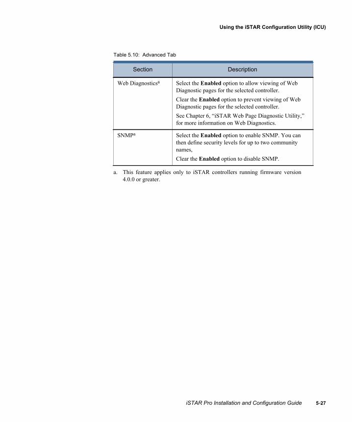
Using the iSTAR Configuration Utility (ICU)
Table 5.10: Advanced Tab
Section Description
Web Diagnosticsa
a. This feature applies only to iSTAR controllers running firmware version4.0.0 or greater.
Select the Enabled option to allow viewing of Web Diagnostic pages for the selected controller. Clear the Enabled option to prevent viewing of Web Diagnostic pages for the selected controller. See Chapter 6, “iSTAR Web Page Diagnostic Utility,” for more information on Web Diagnostics.
SNMPa Select the Enabled option to enable SNMP. You can then define security levels for up to two community names, Clear the Enabled option to disable SNMP.
iSTAR Pro Installation and Configuration Guide 5-27

Configuring RAS
5-2
Configuring RAS When you select a modem or serial connection as the primary or secondary path for a master on the Host tab, the fields on the RAS tab become active (Figure 5.9).
Figure 5.9: RAS Tab
Enter the access information (Phone number, Username, Password, Domain) and select a RAS Host IP Address option. See Table 5.9 on page 5-26 for information about the fields and options on this dialog box.
8 iSTAR Pro Installation and Configuration Guide

Using the iSTAR Configuration Utility (ICU)
Configuring SNMPOn iSTAR controllers running firmware version 4.0.0 or greater, you can enable and configure Simple Network Management Protocol (SNMP) communication.
SNMP communication is enabled on all iSTAR controllers by default. You can use the ICU to:
configure up to two SNMP community names select the security level for each community name specify an SNMP trap manager restrict SNMP communication to a particular SNMP host add the contact information for the person who administers SNMP at
your site
To configure SNMP
1. In the ICU controller list, select the iSTAR controller for which you want to enable SNMP.
2. Right-click and select Edit Controller Information.
3. Select the Advanced tab.
iSTAR Pro Installation and Configuration Guide 5-29

Configuring SNMP
5-3
Figure 5.10: Advanced Tab
4. Click the Configure button. The SNMP dialog box appears.
Note: The Configure button is available only if the Enabled check box is selected.
0 iSTAR Pro Installation and Configuration Guide

Using the iSTAR Configuration Utility (ICU)
Figure 5.11: SNMP Dialog Box
5. Refer to the following table for information about the items on this dialog box.
Table 5.11: SNMP Dialog Box Field Descriptions
Field Description
Community Name Set the SNMP communities that this Controller belongs to. An SNMP device or agent can belong to more than one SNMP community. A device will not respond to requests from SNMP management stations that do not belong to one of its communities. Obtain this information from you Network Administrator.
iSTAR Pro Installation and Configuration Guide 5-31

Configuring SNMP
5-3
6. Click OK to save your configuration and close the SNMP dialog.
Rights Set the access right for the specified community. when an SNMP message is received by the Controller, it is evaluated based on these rights.No Access – The SNMP message from a management system in this community is discarded.Read Only – Only GET, GET-NEXT, and GET-BULK requests are processed. SET requests are not processed from this community. Read Create – SET, GET, GET-NEXT, and GET-BULK requests are processed.
SNMP Trap Manager IP Address or Host Name
Enter the IP address or host name of the SNMP Trap Manager for this iSTAR Controller.
SNMP Hosts Accept SNMP packets from any host – Select this option if you want the iSTAR controller to accept SNMP messages from any host.Only accept SNMP packets from this Host – Select this option if you want the iSTAR controller to accept SNMP messages only from a specified host.IPAddress or Host Name – Specify the IP address or host name of the SNMP Host for this iSTAR Controller.
Contact Specify the snmp-contact, which is a 1- to 64-character string usually containing an emergency contact name and telephone or pager number.
Location Specify the snmp-location, which is a 1- to 64-character string usually containing location information about the Controller.
Table 5.11: SNMP Dialog Box Field Descriptions (Continued)
Field Description
2 iSTAR Pro Installation and Configuration Guide

Using the iSTAR Configuration Utility (ICU)
Connecting to the iSTAR Web Page Diagnostic UtilityThe iSTAR Web Page Diagnostic Utility uses Internet Explorer to view status and diagnostics information. You can start the Diagnostic Utility from the ICU. You can also run the Diagnostic Utility by typing the IP address of the controller into the address bar of Internet Explorer (for example, http://121.12.123.12).
Note: You must use Internet Explorer v5.0 or higher to run the Diagnostic Utility.
To start the iSTAR Web Page Diagnostic Utility from the ICU
1. In the ICU window, select a controller and right-click. A drop-down menu appears (Figure 5.12).
Figure 5.12: Web Page Diagnostic Utility
2. Choose Controller Status.
3. If you configured a Controller password in the C•CURE System Administration > System Variables > Controller Tab (as shown in Figure 5.15), the Enter Network Password dialog box opens (Figure 5.3).
iSTAR Pro Installation and Configuration Guide 5-33

Connecting to the iSTAR Web Page Diagnostic Utility
5-3
4. If a Controller password exists (as shown in Figure 5.15), enter the password in both the User Name and Password fields of the Network Dialog box ().
Figure 5.13: Configure Controller Network Password
Figure 5.14: Enter Controller Network Password in Dialog Box
Note: To configure a Network Controller password, select Admin > Options> System Variables> Controller Password> (enter up to 16 characters).
5. If a Network Controller password was not configured for the utility, the Controller Status web page opens in the default web browser (Figure 5.16).
4 iSTAR Pro Installation and Configuration Guide

Using the iSTAR Configuration Utility (ICU)
If a password is configured in the C•CURE System for the diagnostic utility, the Enter Network Password window opens (Figure 5.15). Continue to step 6. If no password was configured for the utility, the default web browser opens as shown in Figure 5.16.
Figure 5.15: Enter Network Password Dialog Box
6. In both the User Name and Password fields, enter the password you configured in the C•CURE Administration application.
7. Click OK. Internet Explorer opens with the status for the selected controller displayed in the main window (Figure 5.16).
iSTAR Pro Installation and Configuration Guide 5-35

Connecting to the iSTAR Web Page Diagnostic Utility
5-3
Figure 5.16: iSTAR Diagnostic System Web Page
Disabling Web Diagnostics
Web Diagnostics are enabled by default. However, on iSTAR, you can disable Web Diagnostics for selected iSTAR controllers running firmware version 4.0.0 and higher.
To disable Web Diagnostics
1. In the ICU Controller list, select an iSTAR controller that is running firmware version 4.0.0 or greater.
2. Right-click on the controller and select Edit Controller Information.
3. Select the Advanced tab (see Figure 5.10 on page 5-30).
4. In the Web Diagnostics box, clear the Enabled check box, then click OK.
6 iSTAR Pro Installation and Configuration Guide

Using the iSTAR Configuration Utility (ICU)
Sending Messages to Other ICU UsersThe Tools command on the main menu includes an option that lets you send messages to other users who are currently using the ICU.
To send a message to other ICU users
1. From the menu bar, choose Tools>Send ICU Message. The User Message dialog box opens (Figure 5.17).
Figure 5.17: User Message Dialog Box
2. Type your message and click Send. The ICU sends the message to all other ICU users in the subnet.
Note: Use the User Message dialog box to advise other users that you are configuring an iSTAR Classic, iSTAR Pro, or iSTAR eX within a specific cluster. This “good practice” procedure prevents other users from configuring the same iSTAR, and maintains control over iSTAR addresses.
iSTAR Pro Installation and Configuration Guide 5-37

Downloading Firmware Updates
5-3
Downloading Firmware UpdatesYou can use the ICU to quickly download firmware updates to one or more controllers. Before starting the download process, copy the new firmware file to a local or network directory that you can access from the computer on which you are running the ICU.
Note: You can use this procedure to download new firmware only to controllers that are currently using firmware version 3.2.1 or greater.
Before starting the firmware download, be aware of the following issues:
If the public IP address for the PC on which you are running the ICU is different than the IP address assigned to the PC’s NIC card, you have to specify the public IP address of the PC on the ICU Options dialog box. See “Setting the Public IP Address for Firmware Downloads,” on page 5-13 for more information.
If the default port (2020) that is used for firmware downloads is in use by another application on the PC, you have to specify another port to use for firmware downloads. See “Setting the TCP/IP Port for Firmware Downloads,” on page 5-13 for more information.
To download updated firmware to a controller
1. In the ICU window, select the controller(s) that you want to update. You can select multiple controllers by pressing the Ctrl key while you are selecting them.
2. After selecting the controller(s), right-click in the ICU window and select Download Firmware from the pop-up menu (see Figure 5.12 on page 5-33).
Note: You can also start the download process by clicking the icon on the toolbar.
3. The Download Firmware dialog box appears, listing all of the controllers you selected (Figure 5.18).
8 iSTAR Pro Installation and Configuration Guide

Using the iSTAR Configuration Utility (ICU)
Figure 5.18: Download Firmware Dialog Box
4. Click Browse and navigate to the directory in which you stored the firmware image file.
5. Select the firmware image file and click Open. The selected file is displayed in the Firmware Image File to Download box.
6. Click Start Download to initiate the download to all controllers in the Download Firmware list. The firmware is downloaded simultaneously to all controllers in the list. The Progress bar on each line indicates when the download is complete to each controller.
The Progress bar indicates the status of the firmware download to each controller
iSTAR Pro Installation and Configuration Guide 5-39

Downloading Firmware Updates
5-4
0 iSTAR Pro Installation and Configuration Guide
6
The iSTAR Web Page Diagnostic Utility uses a web page interface that is included in the iSTAR Pro firmware. Use the Diagnostic Utility to view diagnostic and status information for a controller or cluster in an Internet Explorer browser window.
Note: The Web Page Diagnostic Utility has not been evaluated by UL.
In This Chapter
Starting the Diagnostic Utility .............................................................. 6-2Navigating the Diagnostic Utility ......................................................... 6-3Viewing the Status Screen .................................................................... 6-4Viewing the Cluster Information Screen .............................................. 6-7Viewing the Object Store Database Screen .......................................... 6-8Diagnostic Screens.............................................................................. 6-10
iSTAR Web PageDiagnostic Utility
iSTAR Pro Installation and Configuration Guide 6-1

Starting the Diagnostic Utility
6-2
Starting the Diagnostic UtilityUse the following procedure to start the Diagnostic Utility and connect to a controller.
To start the Diagnostic Utility
1. In an Internet Explorer browser window, enter the IP Address of the iSTAR Pro controller (for example, http://121.21.121.12) in the browser Address window and press Enter or click Go. The Enter Network Password dialog box appears.
Note: You can also start the Diagnostic Utility from the ICU. See “Connecting to the iSTAR Web Page Diagnostic Utility,” on page 5-33.
Figure 6.1: Enter Network Password Dialog Box
2. In both the User Name and Password fields, enter the password you configured in the C•CURE Administration application (Options>System Variables >Controller)After the login information has been verified, the Controller Status window appears (Figure 6.2 on page 6-3).
Note: The password that you enter for the Diagnostic Utility is different than the one used for the ICU.
iSTAR Pro Installation and Configuration Guide

iSTAR Web Page Diagnostic Utility
Navigating the Diagnostic UtilityThe Diagnostic Utility window is divided into two frames. Use the menu on the left-side frame, shown in Figure 6.2, to navigate to the other screens. The selected screen displays in the right-side frame.
Figure 6.2: Diagnostic Utility Frames
The menu in the left-side frame is the entry point to all the other screens. It remains fixed in the left-side frame while the right-side frame changes according to the menu selection.
Notice the drop-down list at the top of the menu. The MAC address of the selected controller appears in the rectangular box. Once connected to a controller, all of the cluster members associated with that controller are accessible. Connect to them by selecting them from the drop-down list box. Click the down arrow to expand the list. The numbers shown in the list correspond to the associated controllers’ MAC addresses.
Drop-Down List
Menu
Left-Side Frame Right-Side Frame
iSTAR Pro Installation and Configuration Guide 6-3

Viewing the Status Screen
6-4
Viewing the Status ScreenIf the Controller Status screen is not displayed in the right-hand frame, click Status on the menu. A Controller Status screen appears. This screen displays status information for the selected controller. Figure 6.3 shows a portion of a master controller status screen. The information that is displayed for a member controller is slightly different.
Figure 6.3: Controller Status Screen
Status information varies, and depends on the iSTAR firmware version. Table 6.1 shows all status information for the iSTAR Pro controller.
Table 6.1: Status Information Description
Item Meaning
Controller Type Whether the selected controller is a cluster master or member.
iSTAR Pro Installation and Configuration Guide
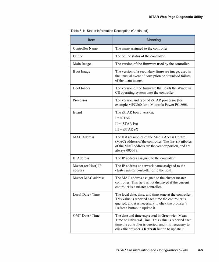
iSTAR Web Page Diagnostic Utility
Controller Name The name assigned to the controller.
Online The online status of the controller.
Main Image The version of the firmware used by the controller.
Boot Image The version of a secondary firmware image, used in the unusual event of corruption or download failure of the main image.
Boot loader The version of the firmware that loads the Windows CE operating system onto the controller.
Processor The version and type of iSTAR processor (for example MPC860 for a Motorola Power PC 860).
Board The iSTAR board version.I = iSTARII = iSTAR ProIII = iSTAR eX
MAC Address The last six nibbles of the Media Access Control (MAC) address of the controller. The first six nibbles of the MAC address are the vendor portion, and are always 0050F9.
IP Address The IP address assigned to the controller.
Master (or Host) IP address
The IP address or network name assigned to the cluster master controller or to the host.
Master MAC address The MAC address assigned to the cluster master controller. This field is not displayed if the current controller is a master controller.
Local Date / Time The local date, time, and time zone at the controller. This value is reported each time the controller is queried, and it is necessary to click the browser’s Refresh button to update it.
GMT Date / Time The date and time expressed in Greenwich Mean Time or Universal Time. This value is reported each time the controller is queried, and it is necessary to click the browser’s Refresh button to update it.
Table 6.1: Status Information Description (Continued)
Item Meaning
iSTAR Pro Installation and Configuration Guide 6-5

Viewing the Status Screen
6-6
DST YES or NO indicates whether or not the controller automatically adjusts the local time setting for Daylight Savings Time when it is in effect.
Boot Date / Time The GMT date and time at which the controller was last booted.
Elapsed Time Since Boot The amount of time that has passed since the system was booted.
Total Program Memory The total amount of controller flash ROM memory, in bytes.
Free Program Memory The number of bytes of controller flash ROM memory not in use.
Percent Free The percentage of controller flash ROM memory not in use.
Total Storage Memory The total amount of SDRAM available for C•CURE access control data.
Free Storage Memory The amount of free SDRAM available for C•CURE access control data.
Total Physical Memory The amount of SDRAM available on the controller.
Master (or Host) Connection Status
The status of the connection to the master controller (for members) or to the host (for masters).
Path to Host Yes or No indicates whether or not the controller has a communications path to the C•CURE host.
Active Communication Type
The communication interface that is currently active.
Secondary Communication Type
Type of communication for secondary connection between the controller and host. This is shown only if a secondary connection was configured for the controller.
PCMCIA Ethernet Card Address
The IP address of the PCMCIA Ethernet card, if the controller has one. N/A if the controller does not have a PCMCIA Ethernet card.
Modem The modem type, if the controller has one. N/A if the controller does not have a modem.
Table 6.1: Status Information Description (Continued)
Item Meaning
iSTAR Pro Installation and Configuration Guide

iSTAR Web Page Diagnostic Utility
Viewing the Cluster Information ScreenClick Cluster on the left frame to display the Cluster Information screen. This screen displays the MAC address and IP address, plus the connection and enabled status, for the master and all members of the cluster.
Figure 6.4: Cluster Information Screen
iSTAR Pro Installation and Configuration Guide 6-7

Viewing the Object Store Database Screen
6-8
Viewing the Object Store Database ScreenClick Database in the left frame to display the Object Store Databases screen. This screen displays the status of the database objects in the cluster. Information about memory displays in the top row.
The information on this screen indicates what is configured on a particular iSTAR Pro. This information can vary from unit to unit.
Figure 6.5: Sample Object Store Databases Screen
Controller SDRAM Memory (in bytes)
You can click on these database names to view more details about the database
iSTAR Pro Installation and Configuration Guide
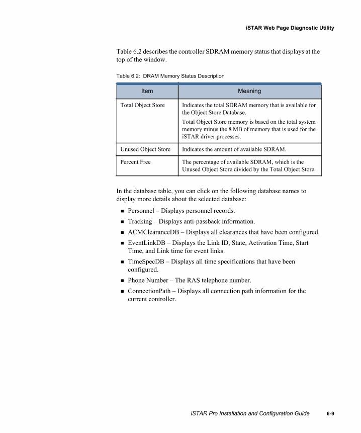
iSTAR Web Page Diagnostic Utility
Table 6.2 describes the controller SDRAM memory status that displays at the top of the window.
In the database table, you can click on the following database names to display more details about the selected database:
Personnel – Displays personnel records. Tracking – Displays anti-passback information. ACMClearanceDB – Displays all clearances that have been configured. EventLinkDB – Displays the Link ID, State, Activation Time, Start
Time, and Link time for event links. TimeSpecDB – Displays all time specifications that have been
configured. Phone Number – The RAS telephone number. ConnectionPath – Displays all connection path information for the
current controller.
Table 6.2: DRAM Memory Status Description
Item Meaning
Total Object Store Indicates the total SDRAM memory that is available for the Object Store Database. Total Object Store memory is based on the total system memory minus the 8 MB of memory that is used for the iSTAR driver processes.
Unused Object Store Indicates the amount of available SDRAM.
Percent Free The percentage of available SDRAM, which is the Unused Object Store divided by the Total Object Store.
iSTAR Pro Installation and Configuration Guide 6-9

Diagnostic Screens
6-1
Diagnostic ScreensDiagnostic screens display information about the:
iSTAR network Readers and I/O devices connected to the iSTAR Pro SID (Subsystem ID) diagnostic level controls
Network Diagnostics
The Network Diagnostics selection displays diagnostic information about iSTAR networks, addresses, data transmissions, protocols, and routing. Figure 6.6 shows a portion of the Network Diagnostics screen.
Figure 6.6: Network Diagnostics Screen
In addition to IP information, this screen also shows TCP, UDP, ICMP, ARP, and routing information.
0 iSTAR Pro Installation and Configuration Guide

iSTAR Web Page Diagnostic Utility
Reader and I/O Diagnostics
The Reader & I/O Diagnostic selection displays information about devices, such as readers, that communicate with the iSTAR Pro (Figure 6.7). This page also displays diagnostic output for iSTAR readers and cards. Refer to “iSTAR Pro Diagnostic Tests,” on page 7-4 for information about iSTAR diagnostic tests.
Figure 6.7: Reader & I/O Screen
iSTAR Pro Installation and Configuration Guide 6-11

Diagnostic Screens
6-1
SID Diagnostic Levels
The SID Diagnostic Levels (Controller Diagnostics) selection displays the Diagnostic Level Control screen (Figure 6.8). From this screen, choose the reports to display or log for the selected controller’s subsystem.
Figure 6.8: Diagnostic Level Control Screen
Each subsystem (e.g., General Controller I/O, Comm Server etc.) has several report categories. To display or log any or all of these, click the appropriate check boxes.
Displaying Diagnostic Information
You can display diagnostic information from the iSTAR Diagnostic Control window using either:
A Real Time Monitoring window, from the ICUor
A terminal session, such as a Hyperterminal session
2 iSTAR Pro Installation and Configuration Guide

iSTAR Web Page Diagnostic Utility
Using a HyperTerminal Session
To configure a HyperTerminal session, connect the RS-232 diagnostic port (P5) on the GCM to the Comm port on a computer with HyperTerminal software. Use a cable with two DB9 connectors with female ends to connect the iSTAR Pro to the Comm port. Connect the ports using a “straight through” (no crossover) connection. That is, connect pin 1 on the comm port to pin 1 on the iSTAR Pro, pin 2 to pin 2, and so forth.
Note: Set the Comm port to 115,200 baud, 8-bit, 1 stop bit, hardware flow control.
To display diagnostic messages using a HyperTerminal session:
1. Open a web browser, and enter the URL or IP address of the iSTAR Pro controller for which you want diagnostic information. The Diagnostic Utility appears.
2. Select SID Diagnostic Level. The iSTAR Diagnostic Level Control page appears.
3. Select the information you want to display for each component and click Submit.
iSTAR Pro Installation and Configuration Guide 6-13

Diagnostic Screens
6-1
Using the ICU
You can also use the ICU to display diagnostic messages. To display diagnostic messages using the ICU:
1. In the ICU main window, highlight the controller you selected in the Web Page Diagnostic Utility, right click, and select Real Time Monitor from the drop-down menu. The Set Diagnostic Levels window displays.
2. Click OK to display the message levels you selected in the Web Page Diagnostic Utility, or select new levels by checking items on the Set Diagnostic Level dialog box.
3. To exit, select Edit and Clear levels on exit to stop diagnostic recording.
Caution: Because diagnostics can slow system performance, Software House recommends that you use them only as needed.
4 iSTAR Pro Installation and Configuration Guide

7
The iSTAR Pro includes an LCD message display. For normal operations, the LCD should be configured to display status messages. For troubleshooting operations, you can configure the LCD to display diagnostic messages about readers, card data, inputs, outputs, network ports and devices.
In This Chapter
Setting the LCD Display....................................................................... 7-2Displaying Status Messages.................................................................. 7-3iSTAR Pro Diagnostic Tests................................................................. 7-4Restricted Functions ........................................................................... 7-15
Using the LCDDiagnostic Display
iSTAR Pro Installation and Configuration Guide 7-1

Setting the LCD Display
7-2
Setting the LCD DisplayThe iSTAR Pro includes an LCD display for status and diagnostic messages. You set the LCD display for the messages you want by using switch S4.
Figure 7.1 shows the location of the LCD and switch S4. See “S4 (Diagnostic and Status Messages),” on page A-4 for a summary of S4 settings.
Figure 7.1: LCD and S4 Components
LCDDisplay
iSTAR Pro Installation and Configuration Guide

Using the LCD Diagnostic Display
Displaying Status MessagesUnder normal conditions, the LCD should be set to display status messages. Status messages include:
iSTAR boot information Date and time Firmware version Controller status information.
Messages typically display for approximately four seconds, separated by an interval of about one second. However, in some instances a message can display until it is cancelled or terminated. For example, the Comm Server can display modem dialing information on the LCD for the duration of the dialing process.
Setting LCD Status Message Display
You can display LCD general status messages for a controller by setting all S4 switch positions 5-8 to On or Off. Setting S4 switch positions 5-8 to On or Off also controls the ICU Block feature, which prevents or allows users from modifying the ICU configuration, as shown in Table 7.1.
When ICU Block is On, the LCD displays general status messages; however, fields in the ICU dialog box are grayed out and cannot be edited. With ICU Block Off, the LCD displays general status messages, and users can read, write, and update the ICU configuration.
To display status messages on the LCD and turn ICU Block On or Off, set Switch 4 positions 5-8 to the following:
Table 7.1: LCD Status Display Messages
Switch Position
Display General Messages (Read only) - ICU Block On
Display General Messages(Read/Write/Update) -
ICU Block Off
S4-5 On Off
S4-6 On Off
S4-7 On Off
S4-8 On Off
iSTAR Pro Installation and Configuration Guide 7-3

iSTAR Pro Diagnostic Tests
7-4
iSTAR Pro Diagnostic TestsiSTAR Pro firmware provides diagnostic information for:
Readers Cards Outputs Inputs Serial (RS-232/RS-485) ports Ethernet and PCMCIA ports PCMCIA internal modem, network, and memory cards DIMM memory Battery charger
Use switch S4 to activate diagnostic tests. Diagnostic information displays on the iSTAR Pro LCD. You do not have to configure the C•CURE 800/8000 or C•CURE 9000 to run diagnostic tests.
Note: Diagnostic tests add overhead to iSTAR Pro processing, and may degrade system performance. When the diagnostic tests are complete, deactivate the test by resetting S4 to display status information.
Card Reader Diagnostics
You can display the most recent card data processed by any reader on the iSTAR Pro either in fast mode or slow mode. When in fast mode, the most recent card data displays on the LED for approximately one second. When in slow mode, the most recent data displays for several seconds.
To set the mode for card reader diagnostics, set S4 switches 5-8 to the positions shown in Table 7.2.
iSTAR Pro Installation and Configuration Guide
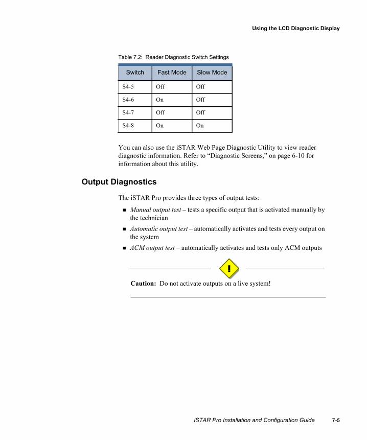
Using the LCD Diagnostic Display
You can also use the iSTAR Web Page Diagnostic Utility to view reader diagnostic information. Refer to “Diagnostic Screens,” on page 6-10 for information about this utility.
Output Diagnostics
The iSTAR Pro provides three types of output tests:
Manual output test – tests a specific output that is activated manually by the technician
Automatic output test – automatically activates and tests every output on the system
ACM output test – automatically activates and tests only ACM outputs
Caution: Do not activate outputs on a live system!
Table 7.2: Reader Diagnostic Switch Settings
Switch Fast Mode Slow Mode
S4-5 Off Off
S4-6 On Off
S4-7 Off Off
S4-8 On On
iSTAR Pro Installation and Configuration Guide 7-5

iSTAR Pro Diagnostic Tests
7-6
Manual Output Test
The manual output test is an end-to-end test that displays information about outputs that are activated manually by a technician. The outputs you are testing can be attached to the iSTAR Pro through readers and R/8 boards. Information displays on the LED for two seconds.
To activate the manual output test, set S4 switches 5-8 to the positions shown in Table 7.3.
Automatic Output Test (All Outputs)
The automatic output test is an end-to-end test that automatically activates all outputs attached to the iSTAR Pro. The outputs you are testing can be attached to the iSTAR Pro through readers and R/8 boards. Output information displays on the LED for approximately one second. However, since outputs activate faster than the one second LCD display, the LCD will not display all output information.
To activate the automatic output test, set S4 switches 5-8 to the positions shown in Table 7.4.
Table 7.3: Manual Output Test Switch Settings
Switch Position
S4-5 Off
S4-6 Off
S4-7 On
S4-8 On
Table 7.4: Automatic Output Test Switch Settings
Switch Position
S4-5 Off
S4-6 On
S4-7 On
S4-8 On
iSTAR Pro Installation and Configuration Guide

Using the LCD Diagnostic Display
Automatic ACM-only Output Test
The ACM-only output test automatically activates all ACM outputs one by one. Test results are indicated by the LED associated with each ACM output.
To activate the ACM output test, set S4 switches 5-8 to the positions shown in Table 7.5.
Input Diagnostics
The input diagnostic test is an end-to-end test that displays information about inputs that are activated manually. Inputs tested can be attached to the iSTAR Pro through the ACM, readers, and I/8 boards. Information displays on the LED for either one second (Position 6, On) or two seconds (Position 6, Off).
To activate input diagnostic tests, set S4 switches 5-8 to the positions shown in Table 7.6.
Table 7.5: ACM-only Output Test Switch Settings
Switch Position
S4-5 Off
S4-6 On
S4-7 Off
S4-8 Off
Table 7.6: Input Test Switch Settings
Position Setting
S4-5 Off
S4-6 On – One second LED displayOff – Two second LED display
S4-7 On
S4-8 Off
iSTAR Pro Installation and Configuration Guide 7-7
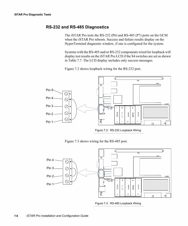
iSTAR Pro Diagnostic Tests
7-8
RS-232 and RS-485 Diagnostics
The iSTAR Pro tests the RS-232 (P6) and RS-485 (P7) ports on the GCM when the iSTAR Pro reboots. Success and failure results display on the HyperTerminal diagnostic window, if one is configured for the system.
Systems with the RS-485 and/or RS-232 components wired for loopback will display test results on the iSTAR Pro LCD if the S4 switches are set as shown in Table 7.7. The LCD display includes only success messages.
Figure 7.2 shows loopback wiring for the RS-232 port.
Figure 7.2: RS-232 Loopback Wiring
Figure 7.3 shows wiring for the RS-485 port.
Figure 7.3: RS-485 Loopback Wiring
Pin 5
Pin 4
Pin 3
Pin 2
Pin 1
Pin 4
Pin 3
Pin 2
Pin 1
iSTAR Pro Installation and Configuration Guide

Using the LCD Diagnostic Display
On board Ethernet and PCMCIA Diagnostics
The on board Ethernet and PCMCIA tests display diagnostic information about Ethernet and PCMCIA connections. The display also includes information about memory and internal modem cards, if they are installed in the PCMCIA slots at the time of the test.
Caution: You must test on board Ethernet network interface cards (NICs) and PCMCIA NICs separately. You can connect only one network interface, either on board Ethernet or PCMCIA, during the diagnostic test.
To test the Ethernet and PCMCIA ports, set S4-5 through S4-8 to the positions shown in Table 7.7.
To test the on board Ethernet port
1. Connect a laptop or computer with ICU Version 3.2.2 or higher to the network that connects to the iSTAR Pro.
2. Connect the Ethernet cable to J4 on the GCM.
Note: You must disconnect the PCMCIA card, if one is installed, when you test the onboard Ethernet port.
3. If you have not already done so, set S4 switches 5-8 to the positions shown in Table 7.7.
Table 7.7: Ethernet, PCMCIA, RS-232, RS-485 Test Switch Settings
Switch Position
S4-5 On
S4-6 Off
S4-7 Off
S4-8 Off
iSTAR Pro Installation and Configuration Guide 7-9

iSTAR Pro Diagnostic Tests
7-1
4. Check the Ethernet LEDs. If the Ethernet is properly connected, LED2 will be lit. If there is communication activity on the Ethernet connection, the LED1 will blink.
5. Verify that the iSTAR Pro is displayed in the ICU (look for the MAC address that is displayed on the LCD).
6. From the ICU, double-click on the entry for this iSTAR Pro to open the Controller dialog box (see Figure 5.8 on page 5-22).
7. On the Controller Identity tab, select the Master Controller option.
8. On the Ethernet Adapter tab, select the Specify an IP address option. Then, in the IP Address field, type 1.1.1.3.
9. If the iSTAR Pro retains the IP address (1.1.1.3), then the Ethernet and Flash have passed the diagnostic test.
10. When the test is complete, set S4 Positions 5-8 to display status messages (see Table 7.1 on page 7-2).
To test the PCMCIA slots
1. Connect a laptop or computer with ICU Version 3.2.2 to the subnet that includes the iSTAR Pro you want to test.
2. Install a PCMCIA Ethernet card and PCMCIA Compact Flash Memory card into the PCMCIA slots on the GCM.
3. Disconnect the Ethernet cable from J4 and connect it to the PCMCIA Ethernet card.
4. Press the Reset Switch on the GCM to reset the board.
5. If you have not already done so, set S4 switches 5-8 to the positions shown in Table 7.7.
0 iSTAR Pro Installation and Configuration Guide

Using the LCD Diagnostic Display
6. Observe the LCD display for test results. If the Ethernet card passes the diagnostic test, you will see the following message on the LCD:
Ethernet PC Card* Passed *
If the Flash Memory card passes the diagnostic test, you will see the following message on the LCD:
PC Memory Card* Passed *
7. When the test is complete, set S4 Positions 5-8 to display status messages (see Table 7.1 on page 7-3).
The LCD displays only success messages. If no message displays, the card is defective/not recognized by the iSTAR Pro, or the PCMCIA port is not communicating.
Modem Card Diagnostics
To test a PCMCIA modem card:
1. Insert the modem card into either PCMCIA slot.
2. Set S4 switches 5-8 to the positions shown in Table 7.7.
The LCD displays only success messages. If no message displays, the card is defective/not recognized by the iSTAR Pro, or the PCMCIA port is not communicating.
Refer to “Qualified PCMCIA Cards,” on page B-3 for information about supported modem cards.
iSTAR Pro Installation and Configuration Guide 7-11

iSTAR Pro Diagnostic Tests
7-1
DIMM Memory Diagnostics
DIMM memory diagnostics test the memory that is installed on the DIMM connector (P3) at the top of the iSTAR Pro. Because the iSTAR Pro transfers data from memory during reboot, you must reboot the iSTAR Pro to begin the diagnostic test, and reboot again to resume normal iSTAR Pro operations.
To test DIMM memory
1. To start the DIMM memory test, set S4 switches 5-8 to the positions shown in Table 7.8.
After setting the switches, the LCD instructs you to reboot the iSTAR Pro.
2. Press the iSTAR Pro Reset Switch (see Figure A.1 on page A-2).The LCD displays the results of the diagnostic test. If the DIMM memory passes, the following message is displayed on the LCD:
DIMM Test Passed Reboot
3. Set S4 switches 5-8 to display status messages (see Table 7.1 on page 7-3).
4. Reboot the iSTAR Pro.
Table 7.8: DIMM Memory Test Switch Settings
Switch Position
S4-5 On
S4-6 On
S4-7 Off
S4-8 Off
2 iSTAR Pro Installation and Configuration Guide

Using the LCD Diagnostic Display
Battery Charger Diagnostics
The function of the iSTAR Pro GCM batteries is to provide enough power to retain the volatile memory data in the event of a power failure.
The GCM batteries provide 24 hour backup, and require 24 hour charge time.
The cells should be replaced as follows:
Every year After a complete discharge
NOTE. The iSTAR Pro Battery Charger test does not indicate battery condition, it only tests the charger circuit.
NOTE The batteries provide power to retain the volatile memory data (clearances, activity, etc.) in the event of a power failure. The batteries do not supply enough power for iSTAR Pro normal operations.
Caution: Risk of explosion if battery is replaced by an incorrect type. Dispose of used batteries according to the instructions.
To test the battery charging circuit
1. Make sure all batteries are the correct type NiMH (Nickel Metal Hydride- AA size. Minimum 2400 milli-amp hours.
2. Activate the battery charger diagnostic test by setting DIP Switch S4 positions 5 through 8, as shown in Table 7.9.
Table 7.9: Battery Charger Test Switch Settings
Switch Position
S4-5 On
S4-6 Off
S4-7 Off
S4-8 On
iSTAR Pro Installation and Configuration Guide 7-13

iSTAR Pro Diagnostic Tests
7-1
3. Remove one battery from the battery charger.
4. Check the LCD display.The following display indicates a functional battery charger:
5. When the test is complete, reinsert the battery and reset S4 switches 5-8 to display status messages (see Table 7.1 on page 7-3).
Charger on: 7.7v - 8.0v
Charger off: 4.5v - 5.5v
4 iSTAR Pro Installation and Configuration Guide

Using the LCD Diagnostic Display
Restricted FunctionsSome S4 settings are reserved, or are used only at the request of Software House Customer Support. Table 7.10 shows reserved and restricted settings.
Table 7.10: Restricted Functions
S4 Switch SettingDescription
Position 1 Position 2 Position 3 Position 4
On On orOff
On orOff
On or Off
Reserved. Do not use these settings unless specifically requested to do so by Software House Customer Support.
Off On Off Off To clear on board DIMM memory and data on Flash memory, set S4 switches 5-8 to these positions, then press the reset button. This resets the iSTAR Pro configuration to the factory default. You will have to reconfigure the IP address and identity parameters if you use these settings.
Off Off On Off Reserved. Do not use these settings unless specifically requested to do so by Software House Customer Support.
Off Off Off On If reset is pressed, causes the iSTAR Pro to reboot using the boot image instead of the main image.
iSTAR Pro Installation and Configuration Guide 7-15

Restricted Functions
7-1
6 iSTAR Pro Installation and Configuration Guide
A
This appendix provides information about switches, reset buttons, jumpers, and status LEDs on the General Controller Module (GCM) and the Access Controller Module (ACM).
In This Appendix
GCM Controls and Indicators.............................................................. A-2ACM Controls and Indicators.............................................................. A-6
Controls andIndicators
iSTAR Pro Installation and Configuration Guide A-1

GCM Controls and Indicators
A-2
GCM Controls and IndicatorsThe GCM contains the following switches and reset buttons for use during hardware setup and configuration.
Reset button – reboots the iSTAR Pro S1 and S2 – configures P6 for RS-232 (default) or RS-485 (do not use) S4 – activates iSTAR Pro diagnostic features LED indicators – indicate Ethernet link and data transmission
Figure A.1 shows the location of GCM controls and indicators.
Figure A.1: GCM Controls and LEDs
iSTAR Pro Installation and Configuration Guide

Controls and Indicators
Component Description
This section describes GCM controls and indicators.
Reset
Push in the reset button (S5) to reboot the iSTAR Pro (when power is on).
S1 and S2 (Configure RS-232)
The S1 and S2 switches configure RS-232 on the P6 component.
Table A.1 shows the default settings that configure P6 for RS-232.Table A.1: RS-232 Default Settings
S2 (Terminate RS-485)
Table A.2 shows the S2 settings that terminate RS-485 on P7.Table A.2: Settings to Terminate RS-485
Cautions: S2 positions 1, 2 and 7 are reserved for iSTAR Pro operations. Do not reset these positions.S2 position 8 sets the Ethernet port to full duplex (Off). In almost all cases, this switch should be in the off position.
Switch 1 Switch 2
1 2 3 4 5 6 7 8 1 2
On Off On Off On Off On Off On Off
Position 5 Position 6
On On
iSTAR Pro Installation and Configuration Guide A-3

GCM Controls and Indicators
A-4
S4 (Diagnostic and Status Messages)
S4 positions 5 through 8:
Activate status messages (with ICU Block on or off) Activate diagnostic tests for troubleshooting Disable DIMM slot memory burst mode
Table A.3 shows S4 switch settings for Positions 5 through 8. Table A.3: S4 Switch Settings for Diagnostic and Status Messages
S4 Switch Setting Description
S4-5 S4-6 S4-7 S4-8
Off Off Off Off ICU Block Off (Read/Write/Update) - Display General Messages
On On On On ICU Block On (Read only) - Display General Messages
Off Off Off On Display card data from last card read (slow mode).
Off On Off On Display card data from last card read (fast mode).
Off Off On Off Display supervised input changes, 2 second LCD display.
Off On On Off Display supervised input changes, 1 second LCD display.
Off Off On On Manual output test (including readers and R/8 boards).
Off On Off Off Automatic ACM output test (does not include readers and R/8 boards).
Off On On On Automatic ACM output test (including readers and R/8 boards).
On Off Off Off Test Ethernet/PCMCIA ports and devices.
On On Off Off Test DIMM memory.
On Off Off On Test battery charger.
On Off On On Disable DIMM slot memory burst mode. You must disable burst mode if you are not using a supported DIMM (see page 1-3) and cannot boot the iSTAR Pro or you are receiving boot errors. After disabling burst mode, the iSTAR Pro will boot normally. After booting the iSTAR Pro, you can set S4-5 through S4-8 to other positions as needed. If the memory does not work in burst mode, disable burst mode when you boot the iSTAR Pro.
iSTAR Pro Installation and Configuration Guide

Controls and Indicators
S4 Restricted Switches
S4 positions 1 through 4:
Are reserved for iSTAR Pro features Activate diagnostic or repair operations for use by Technical Support
representatives.
Table A.4 shows S4 settings for Positions 1 through 4.Table A.4: S4 Restricted Switches
LED Indicators
GCM LEDs indicate the following conditions:
LED1 - Ethernet data transmission LED2 - Ethernet link LED4 - GCM power indicator
Switch SettingDescription
Position 1 Position 2 Position 3 Position 4
On On or Off On or Off On or Off Reserved. Do not set position 1 to Off unless specifically instructed to do so by Customer Support.
Off Off Off Off Normal operation.
Off On Off Off Clears on board DIMM memory and data on flash memory.
Note: This switch resets the iSTAR Pro to the factory default. You must reconfigure the IP address and identity parameters if you use these settings.
Off Off On Off Reserved. Do not use these combinations.
Off Off On On
Off On Off On
Off On On Off
Off On On On
Off Off Off On Causes iSTAR Pro to reboot using the boot image instead of the main image.
iSTAR Pro Installation and Configuration Guide A-5

ACM Controls and Indicators
A-6
ACM Controls and IndicatorsThe ACM contains the following switches and reset buttons for use during hardware setup and configuration.
Reset button – resets ACM software S2 – enables/disables unused Wiegand connections S3 – controls LED display (the position of this switch is inverted) P34 – sets voltage for Wiegand readers LED indicators – indicate ACM power, RS-485 transmit, and RS-485
receive
Figure A.2 shows iSTAR Pro controls and LEDs.
Figure A.2: ACM Controls and Indicators
S2 Wiegand Enable/Disable
P34 (Voltage)Power LED
S4 (RS-485Termination
RS-485 Data Receive LED
RS-485 Data Transmit LED
ResetS3
iSTAR Pro Installation and Configuration Guide

Controls and Indicators
Component Description
This section describes ACM controls and indicators.
Reset
Push in the reset (S1) switch to reboot the iSTAR Pro.
S2
The S2 component contains switches that enable and disable unused Wiegand connections. Table A.5 shows S2 settings:Table A.5: S2 Settings for Wiegand Connections
S3
S3 position 1 sets LED features. This switch and position perform the same function as the JP 19 connector on the iSTAR Classic board.
Table A.6 shows S3 settings for Position 1. Please note that the position of the S3 switch is inverted on the ACM.Table A.6: S3 Switch Settings
Position Component Off On
1 P17 Enabled Disabled
2 P18 Enabled Disabled
3 P19 Enabled Disabled
4 P20 Enabled Disabled
5 P21 Enabled Disabled
6 P22 Enabled Disabled
7 P23 Enabled Disabled
8 P24 Enabled Disabled
LED S3 Position 1 Closed S3 Position 1 Open
Green Low Output to turn on Green(Pin 7 low, Pin 5 high)
High Output to turn on Green(Pin 7 high, Pin 5 low)
iSTAR Pro Installation and Configuration Guide A-7

ACM Controls and Indicators
A-8
S4
S4 switches terminate RS-485 ports. Table A.7 shows S4 switch settings.Table A.7: S4 Switch Settings
Red Low Output to turn on Red(Pin 5 low, Pin 7 high)
High Output to turn on Red(Pin 5 high, Pin 7 low)
Yellow Normally pulses at 1 kHz to control bi-color LED. Goes high to make LED red, low to make LED green. Pulsing makes LED appear yellow.
N/A
Switch RS-485 Component On Off
S1 P25 Terminated Not terminated
S2 P27 Terminated Not terminated
S3 P29 Terminated Not terminated
S4 P31 Terminated Not terminated
S5 P26 Terminated Not terminated
S6 P28 Terminated Not terminated
S7 P30 Terminated Not terminated
S8 P32 Terminated Not terminated
LED S3 Position 1 Closed S3 Position 1 Open
iSTAR Pro Installation and Configuration Guide

Controls and Indicators
LEDS
ACM LEDs indicate the following conditions:
DS1 - RS-485 data received DS2 - RS-485 data transmit DS3 - ACM power
DS1 and DS2 should be on solid. If DS1 and DS2 are blinking, it indicates a reader bus error. In general, this indicates that a hardware unit (such as a reader, I/8 board, or R/8 board) is configured in the C•CURE software but is not seen by the hardware. This may or may not be a hardware failure, depending on the intent of the technician (that is, the hardware may have been configured in the C•CURE software before the hardware has been installed).
Jumpers
The P34 jumper sets voltage for Wiegand readers.
Right – voltage is set at 5 VDC Left – voltage is set at 12 VDC
All readers must operate at the same voltage.
iSTAR Pro Installation and Configuration Guide A-9

ACM Controls and Indicators
A-1
LED and BeepControl
Switch 3 (S3) on the ACM controls the reader LED display and whether the reader beeps on a card read.
Table A.8: S3 LED and Beep Control
The LED control is for read heads connected to the Wiegand (WG) ports. The LEDs on read heads that are connected to the STARn ports are controlled by the RM-4 or RM-4E.
S3-1 and S3-2 provide the same LED control that is available on the RM-4 and RM-4E.
Table A.9 shows the possible settings of S3-1 and S3-2.
Table A.9: S3 LED Control
External Bi-colorLED Control
If both switches are Off, the Function is External Bi-color, which refers to the two LEDs (Red and Green) in the reader. The function is essentially Tri-color because in some cases the LEDs will appear as Yellow.
S3-1 S3-2 S3-3
LED Control LED control Beep control
S3-1 S3-2 Function
OFF OFF External Bi-Color
OFF ON 3-wire (R,G,Y)
ON OFF 1 Wire (A,B,C)
ON ON 1 Wire (A,B,C)
0 iSTAR Pro Installation and Configuration Guide

Controls and Indicators
2 Wire (Red and Green)
There are two instances of External Bi-color; two wire and one wire. With two wire, the Red and Green LED drives are wired as shown in Figure 2
FIGURE 2. External Bi-color (2 wire)
1 Wire (Yellow)
With one wire, the Yellow drive is wired as shown in Figure 3
iSTAR Pro Installation and Configuration Guide A-11

ACM Controls and Indicators
A-1
FIGURE 3. External Bi-color (1 wire)
The Yellow LED drive gets inverted in the read head resulting in a Red LED when the signal is low and a Green LED when the signal is high. If the Yellow LED drive is oscillating, the Red and Green LEDs will oscillate and it will appear to the human eye that the LED is Yellow. The iSTAR Pro will oscillate the Yellow drive at 1 KHz when a Yellow LED display is required.
3 Wire (Red, Green, Yellow)
When S3-1 is Off and S3-2 is On, it specifies Three wire LED control. In this case, the Red, Green, and Yellow LED drives are wired to its associated LED of the same color as shown in Figure 4.
2 iSTAR Pro Installation and Configuration Guide

Controls and Indicators
FIGURE 4. Three wire LED control
When S3-1 is On, it specifies One Wire (A,B,C) mode. In this case, a single LED drive (Red or Green or Yellow) is wired with varying results as shown in Figure 5.
Three Wire LED Control mode is typically used for older read heads that have a single LED that is either On, Off, or flashing.
iSTAR Pro Installation and Configuration Guide A-13

ACM Controls and Indicators
A-1
One Wire (A, B, C)
FIGURE 5. One Wire (A,B,C) LED control
Beep Control Settings
S3-3 Off - Do not Beep on card read.
S3-3 On - Beep on card read.
4 iSTAR Pro Installation and Configuration Guide

B
Part Numbers
This appendix contains the part numbers.
In This Appendix
iSTAR Pro Part Numbers .................................................................... B-2Qualified PCMCIA Cards.................................................................... B-3
iSTAR Pro Installation and Configuration Guide B-1

iSTAR Pro Part Numbers
B-2
iSTAR Pro Part NumbersThe following table shows the part numbers for iSTAR Pro and ACM assemblies:
The following table shows spare battery pack upgrades.
The following table shows additional components and replacements:
Table B.1: iSTAR Pro Part Numbers
Part Number Reader Support Memory
STAR008W-64A GCM and 1-ACM assembly (RM or Wiegand) 1-8 readers
64 MB
STAR016W-64A GCM and 2-ACM assembly (RM or Wiegand) Up to 16 readers
64 MB
Table B.2: Memory Upgrades
Part Number Description
STAR-BATA Spare battery pack - 5 batteriesFor iSTAR Pro only
Table B.3: Additional Components and Replacements
Part Number Description Memory
STAR-ACM8-WA Add-on ACM assembly 8 MB
STARGC-64MBA Add-on GCM assembly 64 MB
STAR-CAN Enclosure N/A
STAR-PS Power supply and cable assembly N/A
iSTAR Pro Installation and Configuration Guide

Part Numbers
Qualified PCMCIA CardsSoftware House has qualified these PCMCIA cards and supports their use in iSTAR controllers. See the Software House price list for details and ordering information.
Internal Modem Card
100BaseT Ethernet Card
Compact Flash Memory
Table B.4: Qualified Modem Cards
Part Number Description
STAR - PCC - MODEM iSTAR Pro PCMCIA modem card for dial-up primary or secondary communication on iSTAR Pro
Table B.5: Qualified Ethernet Cards
Part Number
STAR-PCC-NIC iSTAR Pro PCMCIA 10/100 NIC card for primary or secondary communication on iSTAR Pro
Table B.6: Qualified Flash Memory Cards
Compact Flash Memory Mfg p/n
SanDisk 16-bit card adapter SDAD38A10
SanDisk Compact Flash memory card, 64 MB
SDCFB-64-A10
iSTAR Pro Installation and Configuration Guide B-3
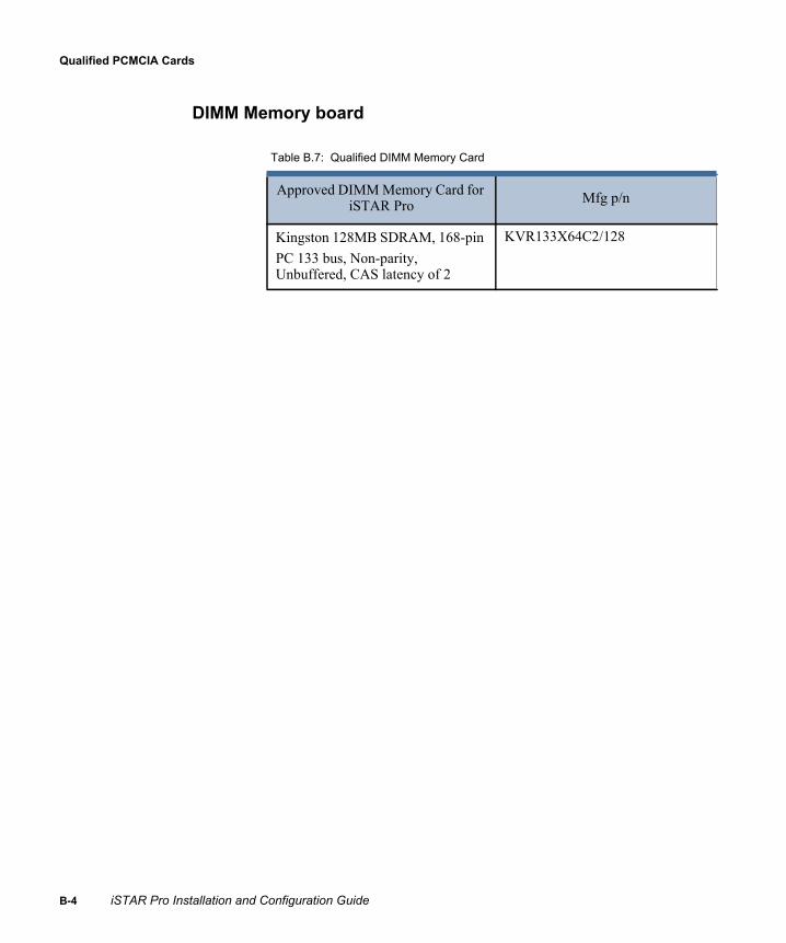
Qualified PCMCIA Cards
B-4
DIMM Memory board
Table B.7: Qualified DIMM Memory Card
Approved DIMM Memory Card for iSTAR Pro Mfg p/n
Kingston 128MB SDRAM, 168-pin PC 133 bus, Non-parity, Unbuffered, CAS latency of 2
KVR133X64C2/128
iSTAR Pro Installation and Configuration Guide

Index
Numerics1 Wire (Yellow) A-11100BaseT Ethernet B-32 Wire (Red and Green) A-113 Wire (Red, Green, Yellow) A-12
AAC power
connecting 4-21fail input 1-11, 4-19
Access Control Module. See ACMACM 1-12 to 1-14
capacities 1-15component description 1-14connecting security devices to 1-17LED indicators 1-14output diagnostic tests 7-7part numbers B-2parts diagram 1-13power input 1-14relay board 1-14reset button 1-14ribbon connector 1-14supervised inputs 1-14
Active ICUs, showing, via status bar 5-19Alternate master configurations 2-7
Alternate master, connections between host and 2-11
ARM-1 1-16Attempting host connection status message 5-18Attempting master connection status message
5-18Automatic output diagnostic test 7-6Auxiliary Relay Module 1-16
BBackward compatibility 1-5Baud rates 3-5Beaconing for Host status message 5-18Beaconing for IP Address status message 5-18Beaconing for Master status message 5-18Beep Control Settings A-14Boot date/time (GMT), controller 6-6Boot errors, cause A-4Broadcasting, across subnet 5-8Burst mode, disabling 1-3, A-4
CCabinet, mounting 1-6Canadian Radio Emissions Requirements xv
iSTAR Pro Installation and Configuration Guide Index-1
Ind
Index
Card data diagnostic tests 7-4Cards 1-12
anti-passback status 1-4smart 1-12Wiegand biometric 1-12Wiegand swipe 1-12
CE Compliance xviCluster Information screen 6-7Cluster members
about 2-5assigning IP addresses to 5-17connections with alternate master and 2-11losing connection with master 2-12primary path and 2-8using C•CURE Administration Application
to configure 5-4, 5-6Clusters
about 2-5definition of 1-3display Object Store Databases screen 6-8displaying Cluster Information screen 6-7events in 1-3maintaining communications 2-10obtaining information about, using ICU 5-8setting parameters 1-19specifying master 2-14system activity and 1-4
Comm Fail status message 5-18Communications
maintaining 2-10modem 3-5specifying methods 2-14supported by iSTAR Pro 2-2
Communications paths 2-9Primary communications path. See Primary
PathPrimary. See Primary PathSecondary communications Path. See
Secondary Path
Communications, baud rates 3-5Configurations
GCM memory 1-11maximum per controller 1-15selecting master in ICU 5-23
configureiSTAR Classic 5-37iSTAR eX 5-37iSTAR Pro 5-37
Configuringa forced door event 1-3controllers using ICU 5-20ICU password 5-12master using ICU 5-4RAS 5-28SNMP 5-29using Controller Communcation Information
window 5-20configuring 5-37Connected to alternate master status message
5-18Connected to Host status message 5-18Connected to Master status message 5-18Connecting
AC power 4-21controller to host via RAS dialup modem
4-17controller to host via RS-232 4-13controller to network 4-11
Connection types 1-2Connections
specifying parameters for primary path 2-14types of 2-8viewing status of controller 1-20
Connectorsexpansion 1-11RJ-45 jack (10bT) 1-11
Control signal, equipment wiring specifications 3-12
ex-2 iSTAR Pro Installation and Configuration Guide
Index
Controller Communication Information window 5-20, 5-21
Controller status screen via web 6-4Controllers
boot date/time (GMT) using web to check 6-6
check available SDRAM memory capacity 6-9
check if auto DST active via web 6-6check master or host IP address via web 6-5check master or host MAC address via web
6-5check total SDRAM memory capacity 6-9check type (master or member) via web 6-4configuring using ICU 5-20connecting to host via RAS dialup modem
4-17connecting to host via RS-232 4-13diagnostic level control reports 6-12display local date/time via web 6-5display Object Store Database 6-8display of GMT via web 6-5displaying in ICU window 5-17displaying status 5-18displaying the Diagnostic Level Control
screen 6-12displaying the number of, on network 5-19displaying type of 5-18entering URL 6-2free memory status 6-6indicating master 5-23MAC address, check via web 6-5maximum configuration 1-15mounting 4-4, 4-6specifying for communications with
C•CURE system host 2-15total flash ROM memory 6-6using web to access 6-2view status of 1-20viewing IP address 5-17viewing MAC address 5-17
Conventions used in this manual xiiiCurrent, determining maximum power
consumption 3-6
DDatabase
check memory still available for controller 6-9
check size of controller 6-9Database information, viewing 6-8Diagnostic debug port 1-11Diagnostic information, displaying 1-4, 6-12Diagnostic LCD 1-4Diagnostic Level Control screen 6-12Diagnostic status, viewing 6-4Diagnostic switch settings A-4Diagnostic tests
ACM output 7-7automatic output 7-6card data 7-4Ethernet and PCMCIA 7-9input diagnostics 7-7manual output 7-6modem and memory card 7-11reader 7-4RS-232 and RS-485 7-8types of 7-4, 7-5
Diagnostic Utility 6-1cluster information 6-7connecting to 5-33database information 6-8features 1-20main screen 6-3navigating 6-3network diagnostics 6-10reader and I/O 6-11SID diagnostic levels 6-12
iSTAR Pro Installation and Configuration Guide Index-3

Ind
Index
starting 6-2viewing status screens 6-4
Dialup connections 1-2Dialup modems
connecting controller to host via RAS 4-17DIMM
memory socket 1-2specifications 1-2supported 1-3
Documentation conventions xiiiDoor contact, equipment wiring specifications
3-12Downloading firmware updates 5-38DRAM
check capacity 6-9check unused capacity 6-9
DST, controller on or off 6-6
EEnclosure, mounting 4-4Environmental requirements 3-4Equipment wiring specifications
door contact 3-12modem, iSTAR Pro 3-12readers 3-13relay control 3-12Request-to-exit 3-12RS-485 3-12supervised inputs 3-12
Ethernetcluster members 2-5connecting controller to network 4-11diagnostic test 7-9options 3-11part numbers B-3ports 1-11
Events, for controllers in clusters 1-3Expansion connector 1-11External Bi-color, A-10
FFail-safe mechanism override xviFCC Class A xivFCC Class B xvFirewalls 2-2Firmware download
setting public IP address 5-13setting TCP/IP port 5-13
Firmware, upgrading 1-4, 5-38Flash memory, installing 4-7Flash ROM 1-4Forced door event 1-3Free memory, controller 6-6Fully qualified domain names 2-4
GGateway router 1-4Gateways 2-2GCM 1-8 to 1-11
component description 1-11controls and indicators A-2expansion connector 1-11features 1-8identifying MAC address 5-17input connectors 1-11LED indicators 1-11parts diagram 1-10power input 1-11reset button 1-11
Global antipassback, status 1-4
ex-4 iSTAR Pro Installation and Configuration Guide

Index
GMT date/time, controller display via web 6-5Green LED A-12Guidelines for setting up primary path 2-14
HHelp, ICU 5-15Host
connecting to controller via RAS dialup modem 4-17
connecting to controller via RS-232 4-13connections between alternate master and
2-11displaying IP address 5-17networking with 1-5
Host connections 4-10 to 4-18using RS-232 4-12via modem 4-15via network 4-10
II/8 module
description 1-16ICU 5-1, 5-1 to 5-39
Advanced tab 5-27assigning cluster member address 5-17assigning master IP address 5-17Attempting host connection message 5-18Attempting master connection message 5-18Beaconing for Host message 5-18Beaconing for IP Address message 5-18Beaconing for Master message 5-18changing password 5-12Comm Fail message 5-18configuring controllers 5-20configuring iSTAR clusters 5-4configuring master controller 5-3
Connected to alternate master message 5-18Connected to Host message 5-18Connected to Master message 5-18Controller Identity tab 5-22controller information displayed using 1-20copying to PC or laptop 5-7displaying host IP address 5-17displaying number of active 5-19displaying parent IP address 5-17displaying type of controller 5-18Ethernet Adapter tab 5-23Host/Master tab 5-25how cluster information is displayed 5-8main window 5-9main window features 5-14Not Connected message 5-18opening monitor controller Diagnostic screen
5-15opening Options window 5-12pinging controllers 5-15RAS tab 5-26rebooting message 5-18refreshing controller information 5-11refreshing window 5-15setting parameters 1-19starting 5-9status of controllers 5-18troubleshooting tools 5-3using on PC or laptop 5-7, 5-20using password window 5-9using the toolbar 5-14using to manually configure the master 5-4WAN configurations 5-4, 5-5
ICU Help 5-15ICU lock 5-8ICU options, setting 5-11ICU password, changing 5-12Identifying master or member 5-18Indicators
iSTAR Pro Installation and Configuration Guide Index-5

Ind
Index
ACM LED 1-14GCM LED 1-11
Input diagnostic tests 7-7Inputs
ACM supervised 1-14connecting to P6 4-19definition of 1-17devices. See devicesGCM connectors 1-11supervised 1-17types of 1-17
Installingchecking site before 3-2equipment requirements 3-2tools required 3-3
Installing Flash memory 4-7Internet, using for iSTAR Pro diagnostics 6-3IP address
assigning to cluster members 5-17assigning to master 5-17displaying cluster member 6-7parents 5-17viewing controller 1-20, 5-17viewing parent 1-20, 5-17
iSTAR board 6-5iSTAR Classic 5-16, 5-37iSTAR controller 5-16iSTAR eX
configuring 5-37iSTAR eX Controller 5-16iSTAR Pro 5-37iSTAR Pro Controller 5-16iSTAR web-based Diagnostic Utility. See
Diagnostic Utility
LLaptop, using ICU on 5-7, 5-20LCD display 1-4, 1-11
configuring for status and diagnostic messages 7-2
displaying status messages 7-3location 7-2
LED Control A-10LEDs
checking GCM A-2function A-5, A-6, A-9function and location A-2
Local address management 2-3Local date/time, controller display 6-5Logging controller diagnostics 6-12Low battery input 1-11, 4-19
MMAC
address in web diagnostic window 6-3address, controller 6-5address, description of 5-22displaying address 5-22GCM label with address 5-17viewing address 1-20, 5-17
Main screen, iSTAR web-based Diagnostic Utility 6-3
Manual output diagnostic tests 7-6Master or host
connection status, using web to check 6-6IP address, assigned to master or host 6-5MAC address, for controller 6-5
Mastersabout 2-5, 2-8assigning IP addresses to 5-17
ex-6 iSTAR Pro Installation and Configuration Guide

Index
cluster members losing connection with 2-12displaying IP address 5-17indicating 5-23primary communications path and 2-8specifying for cluster 2-14using ICU to manually configure 5-4
Memorycheck controller DRAM 6-9
Memory card diagnostic test 7-11Memory configuration, GCM 1-11Memory enhancements 1-2Menu bar, ICU window 5-19Modem 3-5
equipment wiring specifications 3-12Modem cards B-3Modem diagnostic test 7-11Modules, optional 1-16Monitor controller diagnostic screen, opening
5-15Mounting the enclosure 4-4
NName, viewing controller status 1-20Names, controller 5-17Navigating, iSTAR Web Diagnostic Utility (see
Diagnostic Utility) 6-3NetBIOS 2-4Network
communicating via TCP/IP 2-2platforms 2-2requirements 3-4
Network connections 1-2Network diagnostics, viewing 6-10Network Password dialog box 6-2Not Connected status message 5-18
Number of controllers, displaying 5-19
OObject Store Databases screen 6-8Options dialog box, opening 5-12Output, definition of 1-17
PP34
function A-6using A-9
Parameters, setting for cluster 1-19Parent’s IP address, viewing 1-20Part numbers
ACM B-2Ethernet cards B-3iSTAR Pro B-2PCMCIA cards B-3
Passwordconfiguring for ICU 5-12ICU window 5-9network 5-33, 5-35
Path to host, using web to check on 6-6PC, using ICU on 5-7, 5-20PCMCIA 1-11
approved cards B-3diagnostic test 7-9
Physical requirements 3-4Pinging selected controller via ICU 5-15Ports
Ethernet 1-11GCM serial 1-11PC card 1-11
Power
iSTAR Pro Installation and Configuration Guide Index-7

Ind
Index
ACM input 1-14equipment wiring specifications 3-12GCM input 1-11requirements 3-5
Power ratingsRM ports 3-7Wiegand ports 3-7
Power requirementscomponents 3-6PCMCIA Ethernet 3-10PCMCIA modems 3-10Software House readers 3-8third-party readers 3-10
Primary pathguidelines for 2-14main elements 2-8setting up 2-14types of connections 2-8
Public IP address, setting for firmware downloads 5-13
QQueries, broadcasting 5-15Querying subnet 5-8
RR/8 module
description 1-16RAS
configuring 5-28dialup modem connections 4-17
Reader and I/O diagnostics 6-11Reader diagnostic tests 7-4Readers
equipment wiring specifications 3-13
power requirements 3-10Rebooting status message 5-18Recommended PCMCIA Cards B-3Red LED A-12Refresh ICU window 5-15Relay board, ACM 1-14Relay control, equipment wiring specifications
3-12Reports, viewing or logging controller diagnostic
6-12Request-to-exit, (RTE) equipment wiring
specifications 3-12Requirements
baud rate 3-5ground 3-16ground wiring 3-16installation 3-4modem 3-5power 3-5system network 3-4
Reset button A-2, A-6ACM 1-14, A-6GCM 1-11, A-2
Reset, using A-3, A-7Ribbon connector, ACM 1-14RJ-45
Ethernet 10BaseT, equipment wiring specifications 3-12
jack connector (10bT) 1-11RM ports, power ratings 3-7RM-4 1-16RM-4E 1-16ROM, flash 1-4Router, gateway 1-4RS-232 1-11
configuring A-3connecting controller to host via 4-13
ex-8 iSTAR Pro Installation and Configuration Guide

Index
diagnostic test 7-8requirements 3-16
RS-485 1-11diagnostic test 7-8wiring specifications 3-12
SS1
function A-2using A-3
S2function A-6using A-3, A-7
S3function A-6using A-7
S4diagnostic settings A-4restricted settings 7-15, A-5using A-8
Secondary pathsetting up 2-15types of connections 2-9
Security devices, connecting to ACM 1-17Serial connections 1-2Signals
equipment wiring specifications 3-12Single master configurations 2-7Site
checking before installation 3-2installation requirements 3-4
SNMP, configuring 5-29Software House readers, power requirements 3-8Specifications
baud rates 3-5
system cabinet 3-4Starting Diagnostic Utility 5-33, 6-2Static electricity 4-4Status
displaying controller 5-18using Diagnostic Utility to view controller
6-4viewing controller icons 5-17
Status messages, displaying on the LCD 7-3Subnet
querying 5-8using PC or laptop with ICU on 5-7, 5-20
Subsystems, viewing reports for 6-12Supervised Input Translator Board 1-16Supervised inputs 1-17
equipment wiring specifications 3-12System activity, in cluster 1-4System cabinet, specifications 3-4System components 1-6System diagnostic levels, displaying 6-12System diagnostics, viewing controllers 6-12System requirements, network 3-4
TTamper input 4-19TCP/IP port, setting for firmware downloads
5-13TCP/IP, overview of 2-2Three Wire LED Control A-13Toolbar, ICU 5-14Tools, installation 3-3Total memory, controller 6-6Total object store, database 6-9Type of controller, viewing 1-20
iSTAR Pro Installation and Configuration Guide Index-9

Ind
Index
UUL Listing xivUpgrading firmware 1-4URL, entering controller 6-2User message window 5-37
Vversion 6-5Viewing controller diagnostics 6-12Viewing diagnostic information 1-4
WWeb based iSTAR Diagnostic Utility screen 6-3Web diagnostics
controller status screen (also see Diagnostic Utility) 6-4
Wiegand card 1-12biotmetric 1-12proximity 1-12smart 1-12swipe 1-12
Wiegand ports, power ratings 3-7Wiegand proximity 1-12Wiring
ground requirements 3-16requirements 3-12
Wiring specificationscontrol signal 3-12door contact 3-12modem, iSTAR Pro 3-12readers 3-13relay control 3-12Request-to-exit 3-12RS-485 3-12
supervised inputs 3-12
YYellow LED A-12
ex-10 iSTAR Pro Installation and Configuration Guide