by van v alkenburgh nooger & neville, inc. · van valkenburgh, nooger and neville, inc. new...
TRANSCRIPT

basic electronics
by VAN V ALKENBURGH
NOOGER & NEVILLE, INC.
C O M M O N- C O R E
VOL. 2
INTRODUCTION TO AMPLIFIERS
THE TRIODE TUBE
TETRODES & PENTODES
AUDIO VOLTAGE & POWER AMPLIFIERS
rill, RI D E R

basic electronics by VAN VALKENBURGH,
NOOGER & NEVILLE, INC.
VOL.2
JOHN F. RIDER PUBLISHER, INC., NEW YORK

First Edition
Copyright 1955 by
VAN VALKENBURGH, NOOGER AND NEVILLE, INC.
All Rights Reserved under International and Pan American Conventions. This book or parts thereof may not be reproduced in any form or in any language without permission of the copyright owner.
Library of Congress Catalog Card No. 55-6984
Printed in the United States of America

PREFACE
The texts of the entire Basic Electricity and Basic Electronics courses, as currently taught at Navy specialty schools, have now been released by the Navy for civilian use. This educational program has been an unqualified success. Since April, 1953, when it was first installed, over 25,000 Navy trainees have benefited by this instruc-tion and the results have been outstanding.
The unique simplification of an ordinarily complex subject, the exceptional clarity of illustrations and text, and the plan of pre-senting one basic concept at a time, without involving complicated mathematics, all combine in making this course a better and quicker way to teach and learn basic electricity and electronics.
In releasing this material to the general public, the Navy hopes to provide the means for creating a nation-wide pool of pre-trained technicians, upon whom the Armed Forces could call in time of national emergency, without the need for precious weeks and months of schooling.
Perhaps of greater importance is the Navy's hope that through the release of this course, a direct contribution will be made toward increasing the technical knowledge of men and women throughout the country, as a step in making and keeping America strong.
Van Valkenburgh, Nooger and Neville, Inc.
New York, N. Y.
February, 1955
iii

TABLE OF CONTENTS
VOL. 2 — BASIC ELECTRONICS
Introduction to Amplifiers 2-1
The Triode 2-1 1
The Triode Amplifier 9-94
The Tetrode and the Pentode 2-42
The Single-Stage Amplifier 2-55
The Two-Stage RC Coupled Amplifier 2-58
The Transformer-Coupled Amplifier 2-67
The Audio Power Amplifier 2-71
The Output Transformer 2-74
The Push-Pull Amplifier 2-78
Microphones, Earphones and Loudspeakers 2-87
V


INTRODUCTION TO AMPLIFIERS
Examples of Amplification
things you can amplify:
Fact
k
2-1

INTRODUCTION TO AMPLIFIERS
Examples of Amplification (continued)
Sound
2-2
INTRODUCTION TO AMPLIFIERS
Examples of Amplification (continued)
dad
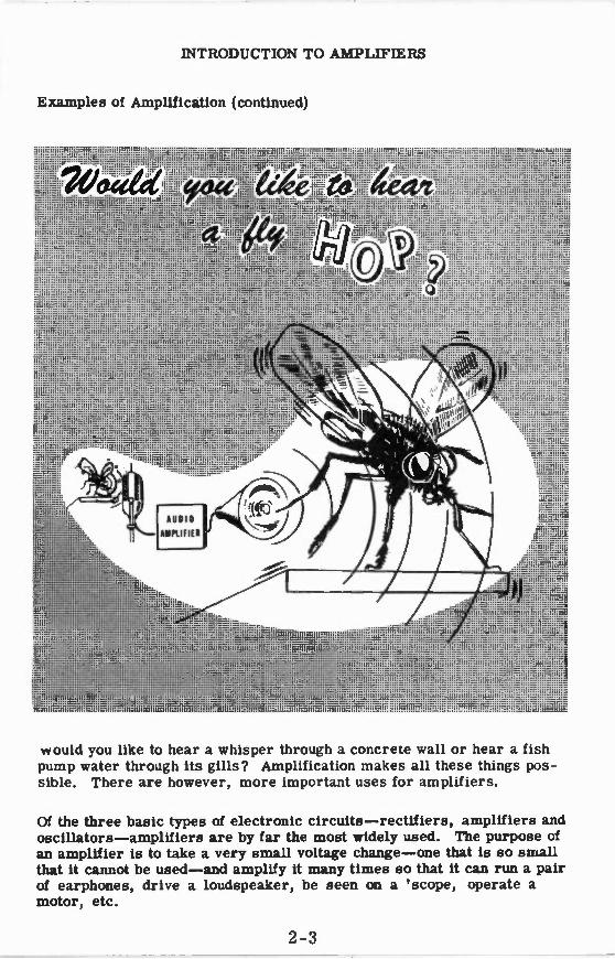
would you like to hear a whisper through a concrete wall or hear a fish pump water through its gills? Amplification makes all these things pos-sible. There are however, more important uses for amplifiers.
Of the three basic types of electronic circuits —rectifiers, amplifiers and oscillators —amplifiers are by far the most widely used. The purpose of an amplifier is to take a very small voltage change —one that is so small that it cannot be used —and amplify it many times so that it can run a pair of earphones, drive a loudspeaker, be seen on a 'scope, operate a motor, etc.
2-3

INTRODUCTION TO AMPLIFIERS
What a Vacuum Tube Can Do
Show You Your Favorite Television Program
1cetactoall ticae tItio94
Operate A Radar System Which Seeks Out Enemy Planes
•,--•••••-••••• •
• -
2-4
INTRODUCTION TO AMPLIFIERS
What a Vacuum Tube Can Do (continued)
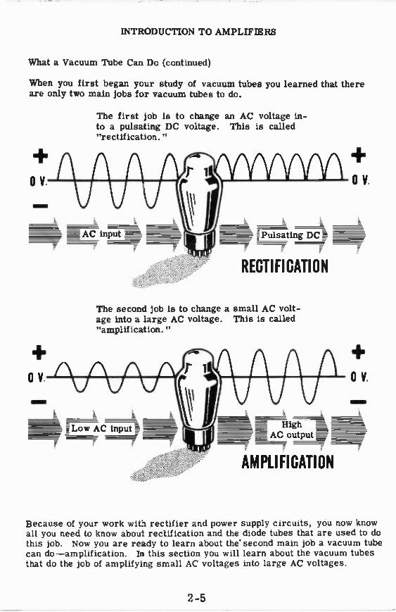
When you first began your study of vacuum tubes you learned that there are only two main jobs for vacuum tubes to do.
The first job is to change an AC voltage in-to a pulsating DC voltage. This is called "rectification."
The second job is to change a small AC volt-age into a large AC voltage. This is called "amplification."
RECTIFICATION
AMPLIFICATION
Because of your work wit li rectifier and power supply circuits, you now know all you need to know abou: rectification and the diode tubes that are used to do this job. Now you are ready to learn about the second main job a vacuum tube can do —amplification. In this section you will learn about the vacuum tubes that do the job of amplifying small AC voltages into large AC voltages.
2-5

INTRODUCTION TO AMPLIFIERS
Types of Vacuum Tubes
A recent survey of vacuum tubes manufactured in the United States showed that there are over 1,200 different types of vacuum tubes available! These tubes come in a wide variety of shapes and sizes—enclosed in glass and metal shells.
2-6
INTRODUCTION TO AMPLIFIERS
Types of Vacuum Tubes (continued)
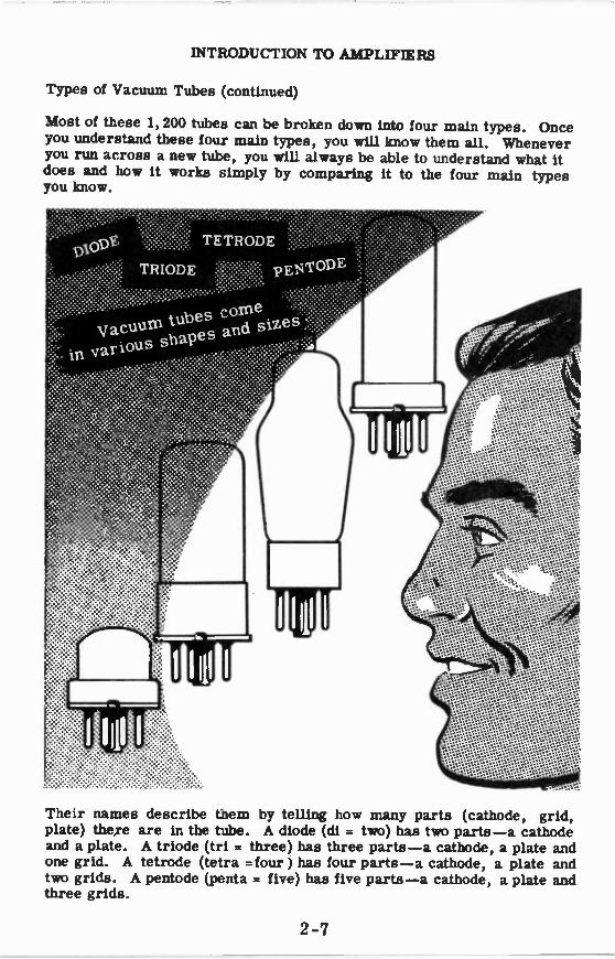
Most of these 1,200 tubes can be broken down into four main types. Once you understand these four main types, you will know them all. Whenever you run across a new tube, you will always be able to understand what it does and how it works simply by comparing it to the four main types you know.
.........•••••••••••••••••••••••••, -****** -"'''''
Their names describe them by telling how many parts (cathode, grid, plate) there are in the tube. A diode (di = two) has two parts —a cathode and a plate. A triode (tri = three) has three parts —a cathode, a plate and one grid. A tetrode (tetra =four ) has four parts —a cathode, a plate and two grids. A pentode (penta = five) has five parts —a cathode, a plate and three grids.
2-7

INTRODUCTION TO AMPLIFIERS
How Vacuum Tubes Were Developed
2,1ezietoftmege oi Vacuum 7ce e „
GRIDS PLATE
CATHODE
FILAMENT
Tubes have developed in a logical sequence. . .
GRIDS
1. from Fleming's valve which consists of two elements, the filament and the plate,
2. to the modern diode in which the filament is replaced by a combination of a filament and a cath-ode (for reasons which will be dis-cussed later) but which is still con-sidered to be a two-element tube,
3. to the triode a three-element tube which contains one grid,
4. to the tetrode a four-element tube with two grids,
5. to the pentode a five-element tube with three grids.
The reason you are being taught vacuum tubes is not so that you will be able to repair one which has gone bad; you will only replace such a tube with a new one. You are being taught about these vacuum tubes in order to understand the circuits which use them and, thereby, to make you a more valuable troubleshooter of electronic equipment.
You will remember from your work with power supplies that thermionic emission —the emitting of electrons by a hot cathode —allowed you to change AC into DC. Notice that triodes, tetrodes and pentodes also con-tain a cathode, which emits electrons, and a plate which collects elec-trons. As you study these tubes you will see how the grids control elec-tron flow to change small AC voltages into large AC voltages.
2-8
INTRODUCTION TO AMPLIFIERS
How Vacuum Tubes Were Developed (continued)
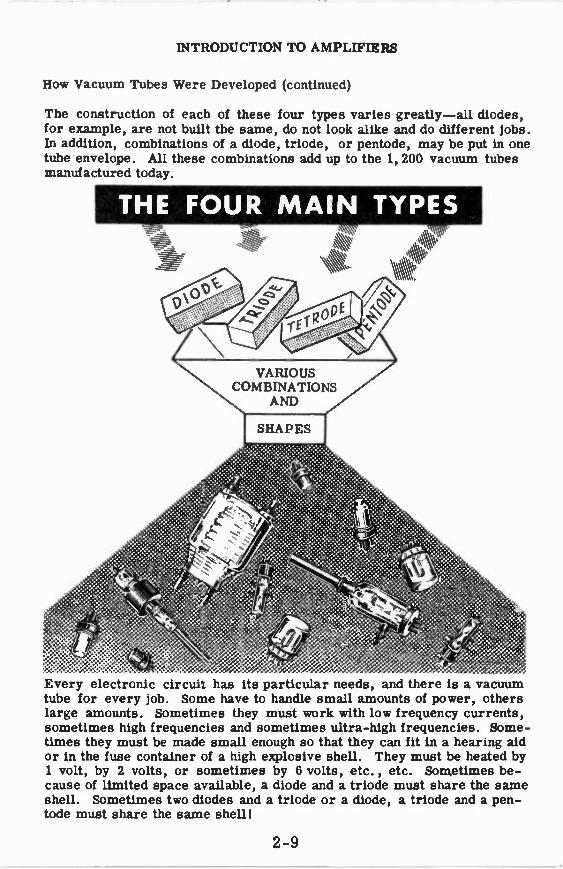
The construction of each of these four types varies greatly —all diodes, for example, are not built the same, do not look alike and do different jobs. In addition, combinations of a diode, triode, or pentode, may be put in one tube envelope. All these combinations add up to the 1,200 vacuum tubes manufactured today.
THE FOUR MAIN TYPES
..e•e »e':e "e".0 ° .e* /X
• . e
Every electronic circui-. has its particular needs, and there is a vacuum tube for every job. Some have to handle small amounts of power, others large amounts. Sometimes they must work with low frequency currents, sometimes high frequencies and sometimes ultra-high frequencies. Some-times they must be made small enough so that they can fit in a hearing aid or in the fuse container of a high explosive shell. They must be heated by 1 volt, by 2 volts, or sometimes by 6 volts, etc., etc. Sometimes be-cause of limited space available, a diode and a triode must share the same shell. Sometimes two diodes and a triode or a diode, a triode and a pen-tode must share the same shell!
2-9

INTRODUCTION TO AMPLIFIERS
Types of Amplifiers
Amplifiers are designed to amplify only those frequencies their type of equipment requires and can be divided into three general groups according to the frequency range of the signals they amplify.
1. Audio Aniplifiers: These amplify a band of frequencies from 15 cycles per second (cps) to 15,000 cps. This is the range of frequencies which the ear can hear —therefore the name "audio." These amplifiers pro-duce a great deal of the amplification in radio receivers, in intercom equipment, in sonar and in many other types of equipment.
2. Video Amplifiers: These are similar to audio amplifiers in that they cover a wide range or band of frequencies and are also similar in de-sign and operation. The frequency band, however, is very much ex-panded, covering frequencies from 30 cps to 6,000,000 cps and higher. Video amplifiers are used primarily to amplify signals for 'scope pres-entations in radar and fire control equipment and in television.
3. Radio Frequency Amplifiers: Unlike the other types, RF amplifiers amplify a narrow band of frequencies, but this narrow band may be any-where within the wide range of frequencies from 30,000 cps to several billions of cycles per second. They are used in radar, fire control, sonar, radio receivers and transmitters. When you tune a piece of equipment, such as a home receiver, you are changing the narrow band of frequencies which the set will amplify.
AUDIO AMPLIFIERS VIDEO AMPLIFIERS R.F. AMPLIFIERS IN
• RADIO RECEIVERS
• INTERCOM EQUIPMENT
• SONAR
IN
• TELEVISION
• RADAR
• SONAR
• FIRE CONTROL GEAR
IN
• RADAR • SONAR
• FIRE CONTROL GEAR
• RADIO RECEIVERS
•TRANSMITTERS
Even though they may look different from one another, amplifiers all work in much the same way. In the following work you will learn the operation of audio amplifiers. They come first because they are the simplest of the three and they will help you to understand how the others work.
2-10

THE TRIODE
Vacuum Tubes and Amplification
One of the most important applications of vacuum tubes is their use to change a small voltage input into a large voltage output. This process of increasing voltages is called amplification.
For example, in an ordinary radio set the tubes take a signal of a few mil-lionths of a volt from the antenna ("aerial") and change it into a powerful signal that is capable of driving a loudspeaker. This requires a great deal of amplification.
You will find that vacuum tubes are used to produce amplification in re-ceivers, in transmitters, in sonar, in radar and in loran; and it is a fore-gone conclusion that when new types of electronic equipment come into use, some of the tubes there, too, will be used for amplification.
One of the tubes which can produce amplification is the triode.
2-11

THE TRIODE
A Typical Triode Tube
Plate
Cathode
Grid
Heater
Anode or Plate
2 -12

THE TRIODE
Seeing How the Triode Works
For purposes of explanation, let's compare the triode to the water system shown below. In the water system, you are interested in controlling the flow of water. One way you can do this is by varying the pressure in the system or, in other words, changing the height of the water tank.
Raise the tank to increase the flow Lower the tank
to decrease the flow
A much more convenient way to vary the flow of water is by using a faucet or valve in the system. Then, by simply turning the faucet, you can con-trol the flow of water. Notice that the water pressure doesn't have to change in order to affect tie flow.
Open the faucet to increase the flow
Close the faucet to decrease the flow
This is similar to the way a triode tube amplifies the flow of current. In the triode an additional element, the grid, is placed in the tube, its pur-pose being to control the flow of current in the tube just as the faucet con-trols the flow of water. You will see that a small voltage variation on this element produces a comparatively large current variation in the tube.
2-13
THE TRIODE
The Control Grid
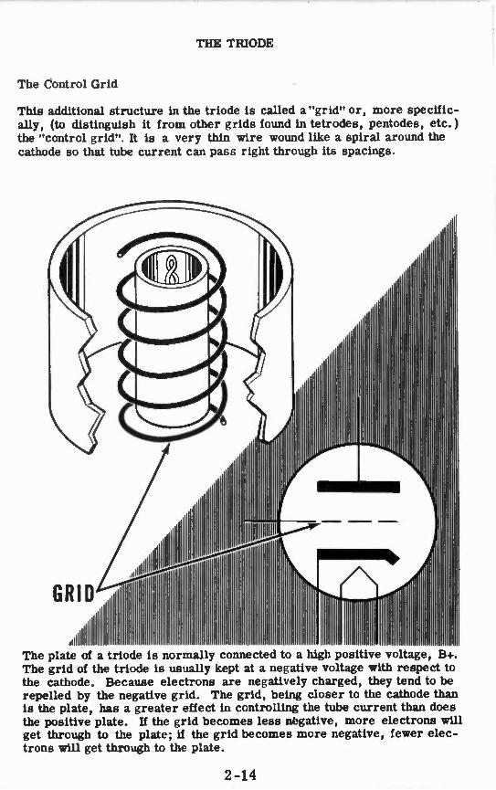
This additional structure in the triode is called a "grid" or, more specific-ally, (to distinguish it from other grids found in tetrodes, pentodes, etc.) the "control grid". It is a very thin wire wound like a spiral around the cathode so that tube current can pass right through its spacings.
6
The plate of a triode is normally connected to a high positive voltage B+ The grid of the triode is usually kept at a negative voltage with respect to the cathode. Because electrons are negatively charged, they tend to be repelled by the negative grid. The grid, being closer to the cathode than is the plate, has a greater effect in controlling the tube current than does the positive plate. If the grid becomes less negative, more electrons will get through to the plate; if the grid becomes more negative, fewer elec-trons will get through to the plate.
2-14

THE TRIODE
The Control Grid (continued)
This is what happens when you vary the DC voltage (called "bias") on the control grid. The plate is very positive and tends to attract electrons. If
the grid is negative, it tends to repel electrons. Space charge Grid
Cut-off
When the grid is made sufficiently negative, its tendency to hold back the electrons will just equal the plate's pull on the electrons and no current will flow. The point at which the two effects are balanced is called "cut-off." When the grid is more negative than this, the tube is operating "beyond cut-off" and no current flows.
Less than cut-off
When the negative charge on the grid is reduced, a few electrons manage to get from the space charge to the plate.
Much less than cut-off
When the grid voltage is reduced further or made equal to zero, more current will flow from the space charge to the plate.
Saturation
If the grid is made positive with re-spect to the cathode, still more cur-rent will flow. A point will be reached when the grid is so positive that the electrons flow from the cathode as fast as the cathode can emit them. This is saturation and a still further increase in grid volt-age will not cause an increased cur-rent to flow.
2-15
a ••••
••••
•••••• eeee e
• • ••
Plate

THE TRIODE
How the Triode Is Similar to the Diode
Since the only difference between the two tubes is the presence of a grid, you might expect to find several similarities between them.
The triode's cathode and filament are no different than the diode's and, therefore, everything that was said about a diode's electron emission is also true of the triode's. In both tubes the emission (and therefore satu-ration) depends upon the filament voltage. In both, burned-out filaments are the most common cause of failure and, in both, cathode emission will decrease as a tube is used.
DIODE... *ea ci9441
•
TRIODE
As in the diode saturation in a triode occurs because there is a limit to the amount of current which the cathode can emit. In the triode, satura-tion (limiting current) can be reached at a lower value of plate voltage if a positive voltage is applied to the grid; in the diode, of course, it depends only on the plate voltage.
On the other hand, if the grid is made sufficiently negative, no current will flow. The value of grid voltage which reduces the current to zero is called the "cut-off" voltage. Increasing the negative grid voltage beyond this point will have no effect since the tube is already cut off. Cut-off also de-pends upon the triode's plate voltage; with a more positive plate voltage, a more negative grid voltage will be necessary to produce cut-off.
In a diode current flows only when the plate is positive, and no current flows when the plate is negative. In a triode, however, the plate can be positive and still no current flows if the grid is sufficiently negative. The cut-off point of a triode depends upon the particular tube (how it is con-structed) and upon the value of plate voltage.
2-16
THE TRIODE
How Amplifiers Work
You have found out a little about how important amplifier circuits are in equipment. Now you are ready to find out how they work.
It's all very simple —a vacuum tube does the entire job of amplifying if you provide it with the proper operating voltages and connections. If you supply the proper voltages to the various tube elements, a small change in voltage applied to the grid causes a large change in voltage on the plate. The pro-duction of a large voltage change from a small voltage change is called "amplification."
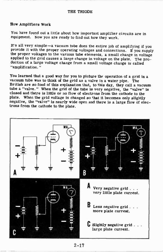
You learned that a good way for you to picture thr operation of a grid in a vacuum tube was to think of the grid as a valve Li a water pipe. The British are so fond of this explanation that, to this day, they call a vacuum tube a "valve." When the grid of the tube is very negative, the "valve" is closed and there is little or no flow of electrons from the cathode to the plate. When the grid voltage is changed so that it becomes only slightly negative, the "valve" is nearly wide open and there is a large flow of elec-trons from the cathode to the plate.
Very negative grid . . . very little plate current.
2-17

THE TRIODE
How Amplifiers Work (continued)
Now a small flow of electrons from the cathode to the plate means that only a small number of electrons flow from the plate to the B+ lead of the pow-er supply, and a large flow of electrons from cathode to plate means a large current flow from the plate to the B+ lead of the power supply.
A change in current appearing at the plate of a tube is of no direct use, but, if this plate current change can become a plate voltage change, the orig-inal voltage change appearing at the grid will have been amplified. The way to accomplish this is to put a resistor between the plate and B+. You know that whenever the electron flow through a resistance changes, a volt-age change is produced across that resistance. This voltage change is many times larger than the voltage change on the grid. Since the plate or output voltage changes by the same amount as the voltage across the re-sistor, the amplified grid voltage change appears at the output.
• VERY NEGATIVE GRID
• VERY LITTLE PLATE CURRENT
• VERY LOW VOLTAGE DROP
ACROSS PLATE LOAD RESISTOR
• LESS NEGATIVE GRID
• MORE PLATE CURRENT
• LARGER VOLTAGE DROP ACROSS PLATE LOAD RESISTOR
• SLIGHTLY NEGATIVE GRID
• LARGE PLATE CURRENT
•VERY LARGE VOLTAGE DROP
ACROSS PLATE LOAD RESISTOR
Using this circuit with certain types of vacuum tubes, the change in plate voltage can be made more than 200 times the change in grid voltage —a voltage gain or amplification of over 200.
2-18
THE TRIODE
How Amplifiers Work (continued)
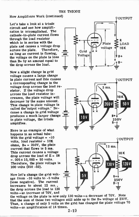
Let's take a look at a triode circuit and see how amplifi-cation is accomplished. The cathode-to-plate current flows through the load resistor which is in series with the plate and causes a voltage drop across the plate. Therefore, as long as current is flowing, the voltage on the plate is less than B+ by an amount equal to the drop across the load.
Now a slight change in grid voltage causes a large change in plate current and this causes a corresponding change in the voltage drop across the load re-sistor. If the voltage drop across the load resistor in-creases, the plate voltage will decrease by the same amount. This change in plate voltage is called the"output voltage." Be-cause a change in grid voltage produces a much larger change in plate voltage, the triode amplifies.
M EI
W WI
IGrid 1 Voltage
1 •—
VOW
Here is an example of what happens in an actual tube: With the grid voltage = -10 volts, load resistor = 10K ohms, B+ = 250V, the plate current that flows is 5 ma. This current causes a voltage drop across the load of E = IR =. 005 x 10, 000 = 50 volts. Therefore, the plate voltage is 200 volts (250 -50).
Now let's change the grid volt- age from -10 volts to -5 volts T B+ (less negative). The current I 250V
increases to about 12 ma., B 1,the drop across the load is 120 .....• =I
V V
volts —an increase of 70V, and the voltage on the plate is now only 130 volts —a decrease of 70V. Note that the sum of these two voltages still adds up to the B+ voltage of 250V. Thus, a change of only 5 volts on the grid has changed the plate voltage 70 volts —an amplification of 14 times.
2-19
V
Plate
voltage X X
OUTPUT
LOAD
10K
B+

THE TRIODE
Tube Characteristics —Amplification Factor
Since the grid voltage and plate voltage can be used to control the flow of current to the plate, it is important to see which does the better job. If you look at the results of tests, you will see that a small change in grid voltage can produce a large change in plate current while a much larger change in plate voltage is necessary to produce the same plate current change.
The ratio of the effectiveness of the grid and plate in controlling plate cur-rent is called Mu, and the Greek letter iu is used to represent it.
From these results we can say that the grid of the tube is much more ef-fective than the plate in controlling plate current.
Change in plate voltage P- to produce the same change in plate current. Change in grid voltage
Actually the Mu of tube is much more than a ratio. It tells you how much a vacuum tube is able to amplify a signal that is applied to its grid. For example, suppose you find that when the grid voltage is changed from -2 to -4 (a change of 2V) the plate current changed the same amount as it did when the plate voltage was changed from 140V to 100V (a change of 40V). The ratio of these two voltage changes is 20 to 1, which means that if one volt of AC is applied to the grid of the tube, 20 volts of AC will ap-pear in the plate circuit. The tube, therefore, has amplified an AC sig-nal 20 times. For this reason the Mu of a tube is also known as the am-plification factor.
= —40 - 20 2
2-20

THE TRIODE
Tube Characteristics —Plate Resistance
The plate resistance of a tube is the internal opposition offered, between the cathode and plate, to the flow of the alternating component of plate cur-rent. When the tube is cperating with an AC voltage on the grid, the num-ber of electrons flowing to the plate changes, and this affects the internal or plate resistance of the tube.
This plate resistance is :he ratio of a change in plate voltage to a change in plate current with the grid voltage constant. For example, the 6C5's plate resistance can be determined from the results of a test where the plate voltage will be varied and plate current values recorded for a con-stant grid voltage. Suppose the test curve indicates that a change in plate voltage from 100V to 150V produced a change in plate current of 5 ma. Since the plate resistance is —
Change in plate voltage r - —for a constant grid voltage P Change in plate current
then
50 T . - 10' 000 ohms. P .005
The plate resistance is not the same for all vacuum tubes. For triodes it will range from 2,000 to 100, 000 ohms and for pentodes it may be as high as 1 megolun.
2-21

THE TRIODE
Tube Characteristics —Transconductance
So far you have learned about two characteristics of vacuum tubes —theiu or amplification factor and the internal plate resistance —rp. Another characteristic —transconductance —is obtained from the relationship of ft and rp. Transconductance is a measure of how effective the grid is in controlling plate current and it is expressed as the ratio of/i.-to rp.
At Transconductance (g m ) = in mhos p i
In simplified form, gm represents the effect of a changing grid voltage on plate current with the plate voltage held constant.
The gm of a tube is expressed in micromhos which is one millionth of a mho, pronounced "mo" —ohm spelled backwards. It is used as the unit of transconductance since conductance is the opposite of resistance.
Using the ». and r from the previous sheets, the gm of the 6C5 can be determined.
20 gm _ f— r 10 000 - .002 mhos
P gm = 2000 micromhos
For most vacuum tubes, the transconductance is usually several thousand micromhos. Tubes with a high », and low rp will have a high gm .
• , ,
DETERMINING THE 117freli ateigeleeeetagee OF A TRIODE
-.; • • . - yew_ • - vs t..-,740
2-22

THE TRIODE
Review of Triode Characteristics
Curve 1: You can see that cut-off for this particular tube is about -14 volts with 200 volts on the plate. As the grid voltage is made less negative, the current increases along the Eg-lp curve. A portion of the curve is straight or linear. On this linear portion the plate current variations are uniformly proportional to the grid voltage variations. In this linear region a change of 2 volts on the grid produces a change of about 4 ma. in the plate current. The graph shown here is called the E -IP curve. E = grid voltage and Ip= plate current.
Curve 2: With the grid voltage set at -8 volts, it is seen that changes of plate voltage affect the plate current. But a 10-volt change on the plate causes only a very small change in the plate current. By comparing the results in curve 1 and curve 2, you can see that the grid exerts a greater control on the plate current than does the plate.
Curve 3: While the tube is cut off' (from grid voltages of -14 and be-yond) no current flows and there is no voltage drop across the plate load resistor. The plate voltage is equal to B+ while the tube is cut-off. When the grid voltage becomes less negative, plate current flows and a voltage drop is developed across the load resistor, causing the plate voltage to drop. Along the linear portion of the curve, a 2-volt change on the grid produces a change of about 30 volts on the plate. This is a gain (amplification of 15,
100
Plate Voltage = 200V 24
20
14 12 10 8 6 4 2 0 2 4
— E = Grid Voltage
5
4
a 3 cyj
2
1
0 70 1 0 150 190 230 270
Plate voltage
y11 [ W I il Grid Voltage = -8V
14 12 10 8 6 4 2 0
Grid voltage
2-23

THE TRIODE AMPLIFIER
Grid Bias Voltage
You should know how the plate current of a triode behaves under different operating conditions. If you look at curve 1 on the previous page, you will see that when the grid is made positive with respect to the cathode, the plate current rises to high values. When the grid is made sufficiently negative with respect to the cathode, plate current drops to zero. These are the extreme conditions in the operation of a triode.
We are concerned with triodes used as amplifiers, and for this purpose they are normally operated with the grid negative to prevent distortion of the signal. This confines the operation to the left portion of the Eg-Ip curve (curve 1). The voltage which keeps the grid negative is called the "grid bias voltage." Grid biasing is simply the process of making the grid negative with respect to the cathode.
When a tube is used as an amplifier, two voltages in series are applied be-tween grid and cathode:
1. The negative DC grid bias voltage which fixes the point of operation on the Eg-Ip curve. This bias voltage may be obtained from a battery or any other source of DC voltage. Various types of bias supplies will be discussed later.
2. The AC signal voltage, which for the present will be in the audio fre-quency range.
In the sheets which follow, you will see how the AC signal adds to and sub-tracts from the bias voltage to produce corresponding changes in plate
current.
Type 6C5
Eg-Ip curve m o m
f....°11L 1::::..:-.1111 W/
IIM MINNIAll 1111111111111111111 M MEM MI1111111 M1111111111/11111 11111111111111 M1111 IMENVAII MIll INEllEd11111111 111,%111111 M111
Ip ma.
18
16
14
12
10
8
6
4
2
-16-14 -12-1Q - -6 -4 -2 00 Eg volts
2-24

THE TRIODE AMPLIFIER
Grid Bias Voltage (continued)
If an AC signal is applied to the grid, the current flowing in the plate cir-cuit will vary in the same manner as the signal voltage. The positive half cycle of the applied signal voltage is in series opposing with the bias volt-age and therefore subtracts from it. The negative hall cycle of the signal voltage is in series aiding with the bias voltage so that addition of the two voltages takes place. As a result, the AC signal voltage causes the grid to.cathode voltage to be alternately less negative and more negative. This varying negative voltage between grid and cathode allows more and less current to flow so that the plate current variations will be a duplicate of the applied signal voltage.
THIS 0
-2
-8
-10 -
= THIS COMBINATION OF DC BIAS
AND 4C Signal Patage
-6 1 -4 , -10 )
Ili THIS
2-25

THE TRIODE AMPLIFIER
Grid Bias Voltage (continued)
Let us consider the following example which will illustrate the points just made. Suppose a 6C5 triode is connected in a circuit with -4V bias volt-age applied to the grid and +200V applied to the plate. With no signal ap-plied, the plate current will be a steady 11 ma. This can be seen by re-ferring to the Eg-Ip curve.
When an AC signal of 2V is applied to the grid, the positive half cycle will subtract 2V from the bias causing the grid to cathode voltage to change from -4V to -2V. The negative half cycle will add to the bias and cause the grid to cathode voltage to change from -4V to -6V. You can see that the grid to cathode voltage is varying from -2V to -6V around the -4V bias.
The plate current depends on the amount of negative voltage between grid and cathode. This negative voltage is now varying in the same manner as the applied signal. Therefore, the plate current will vary in accordance with the applied signal.
When the grid voltage varies so that the plate current varies in accord-ance with the applied AC signal, the amplifier is called "Class A," and is operating on the linear portion of the Eg-Ip curve. You will learn more about the classes of operation a little later.
Grid Voltage Plate Current
r-
4V L _
LINEAR OPERATION ON THE Eg-Ip CURVE
12-r--r -4- 1-0
8
1- 6
; 4
; I 2
1 o -16-14-12-10-8-6-4-2 0 Eg volts
Input Signal
Bias
Maximum
Ip = 16
Zero signal
Ip = 11
Minimum
Ip = 6
2-26

THE TRIODE AMPLIFIER
Why Proper Bias Is Necessary
To obtain an amplified output voltage at the plate we must use the plate current variation. In the example on the previous sheet, a 5 ma. AC component was produced in the plate circuit by applying a 2V AC signal to the grid.
Suppose we look at the plate circuit of the triode. If an 8,000 ohm plate load resistor (RL) is used, the steady or zero-signal plate current of 11 ma. will produce a DC voltage drop across the load of Ez Ix R= . 011 x 8000 = 88V. The DC plate voltage is 200V and the total DC voltage (B+) is the sum of the load voltage and plate voltage or 288V.
On the next sheet you will see now the load voltage and the plate voltage change when the signal is applied to the grid.
9_97

THE TRIODE AMPLIFIER
Why Proper Bias Is Necessary (continued)
When the signal is applied to the grid, the plate current increases to 16 ma. (5 ma. increase) and decreases to 6 ma. (5 ma. decrease). When 16 ma. flows through the load, the voltage drop across the load will be E= IxR= .016 x 8000 = 128V, an increase of 40V (128 -88 40V). This will make the plate voltage decrease joy since the total voltage must always add up to the B+ voltage of 288V. Therefore, the plate voltage will decrease from 200V to 160V. (Note: 160V + 128V = 288V)
When the plate current decreases to 6 ma. the voltage drop across the load will be E.= IxR =. 006.x 8000 = 48V, a 40V decrease from its steady value of 88V. Since the total voltage must still be up to 288V, the plate voltage will increase from its steady 200V to 240V. (Note: 240V + 48V = 288V).
You can see from the illustration below that the 5 ma. AC component of plate current produces a 40 volt variation across the plate load resistor and an equal and opposite variation in plate voltage. Since a 2V AC signal on the grid initially produced the plate current variation, the 40V signal at the plate is an amplified version of the grid signal.
A 2V signal on the grid has produced a 40V signal at the plate which means that we have amplified the signal 20 times. Note that this amplified signal at the plate is 180 degrees out of phase with the signal on the grid.
You will see on the next sheet that the correct bias is necessary if the plate current variation and likewise the plate voltage variation is to be an exact duplicate of the grid signal.
Plate voltage variation —output signal
+240
40V
+20
40V
+16
+12
Steady plate voltage
Load voltage variation
40V
+88
+48
0
I. 4Dv
Steady load voltage
PLATE At4D LOAD VARIATIONS
2-28

THE TRIODE AMPLIFIER
Why Proper Bias Is Necessary (continued)
Notice that although the signal itself was positive during one half cycle, the grid to cathode voltage was never positive —it just became more nega-tive or less negative. The bias point for this amplifier was selected so that it fell in the center of the straight-line or linear portion of the Eg-Ip curve. Operation on the linear portion is essential if the output wave form is to have the same shape as the input wave form. Operating at incorrect bias voltages will produce distortion of one form or another. If too much bias is used, (making the grid voltage more negative) the signal will drive the tube into cut-off durilg the negative half cycle and produce a distorted plate current variation. If too little bias is used, the signal will drive the grid positive during the positive half cycle. This will cause the grid to take some electrons from the cathode that would normally have gone to the plate. Again the result is a distorted plate current variation. These con-ditions are illustrated below.
Distortion will result with the correct bias voltage if the input signal is too large. The large signal will drive the grid into both the positive and the cut-off regions —producing distortion.
You can now see that proper bias is necessary if the plate current varia-tion is to look exactly like the grid signal variation. If the amplifier tube is biased in the center of the linear portion of the Eg-Ip curve and the tube is not overdriven (excessive signal), very little distortion will result. In-correct bias will result in a distorted output signal.
Ip ma.
18
16
14
12
10
8
3
4
2
Distortion due to non-linearity of Eg-Ip curve
-16-14-12-10-8 -6 -4 -2 9 Eg volts
I Distortion due to tube cut-off
Cut-off' Bias
Distortion due to grid becoming
positive
-16-14-12-10-8 - -4 - Eg volts
• ..
181
16 I-
14
12
101
0
8
I
6
4
2 I
0 +2
Bias
2-29

THE TRIODE AMPLIFIER
Classes of Amplifiers
The class of an amplifier is determined by its point of operation on the Eg-lp curve. There are three major classes of amplifiers —Class A, B and C. Class A amplifiers are biased to operate in the center of the linear portion of the Eg-Ip curve. The amplifier described in the previous sheets is a Class A amplifier. Class B amplifiers are biased to operate near cut-off and Class C amplifiers operate at a point where the bias volt-
age is equal to twice the cut-off voltage of the tube.
The figure below shows the bias voltages for the three different classes of amplifiers. For this particular tube, the bias would be -2V for Class A operation. Since Class B operates at cut-off, its bias voltage must be -4V. For Class C operation, the bias must be -8V because a Class C am-plifier operates at a bias equal to twice the cut-off value.
Linear portion
of curve
No plate current flowing
-12
Flat caused by grid drawing current
C ur rent flowing all the time
Current flows half the time
) Current flows less than
half the time
Grid is positive
2-30

THE TRIODE AMPLIFIER
Classes of Amplifiers (continued)
The figure shown on the previous sheet is a comparison of the operating characteristics of Class A, B, and C amplifiers. This is what you should see from the illustration —
Class A
The signal is small. It is never large enough to drive the grid either positive or beyond cut-off. Plate current flows during the complete cycle of signal input. The plate current variation is an exact dupli-cate of the grid signal.
Class B
The signal is larger than for Class A. The grid may be driven posi-tive. The signal drives the grid beyond cut-off for approximately half the input cycle. Only the positive half cycle of input appears in the plate circuit. The total plate current change is much greater than the change produced by Class A operation. Plate current flows for ap-proximately half the complete cycle. Plate current is zero when no signal is put into the grid.
Class C
The applied signal is the largest of the three classes. The grid is driven beyond cut-off and into the positive grid region. The plate cur-rent variation is the largest of the three classes. The peak of the current wave has a dip because the control grid is drawing current, thereby reducing the amount of current available to the plate. Plate current flows for less than half a cycle of input voltage. Without a signal on the grid, nc plate current flows. A large signal voltage is necessary to drive the grid positive during each cycle. This class is used only in RF (radio frequency) power amplifiers.
The Class A amplifier is used primarily as a voltage amplifier. Class B and Class C amplifiers are used as power amplifiers and are designed to deliver high currents.
There are combinations of Class A and Class B amplifiers and these are called Class ABi and AB2. Class ABi amplifiers are biased to a point slightly more negative than Class A amplifiers. Class AB2 amplifiers are biased to a point slightly less negative than that of Class B. These classes of operation are actually compromises between Class A and Class B.
2-31

THE TRIODE AMPLIFIER
Battery Bias
Battery bias was chosen for the first illustration of bias because it is the easiest to understand. In actual practice, you will find it used only in the laboratory or for experimental work. The battery type is reliable and ef-ficient, but the size and weight of batteries make it difficult to use in
most equipment.
Whenever batteries are used as a source of bias voltage, it is desirable to use a combination of cells in series that add up to the required voltage. With this arrangement, it is not necessary to use regulating devices, such as potentiometers, which draw current from the battery and gradually consume its power. Most bias or "C" batteries are made in multiples of 4-1/2 volts -4-1/2, 9, 18 volts and higher. These batteries are tapped for intermediate voltages. The negative terminal of the battery is con-nected to the grid through the resistor Hg, the positive terminal is con-nected to the cathode. This makes the grid negative with respect to the
cathode.
2-32

THE TRIODE AMPLIFIER
Power Supply Bias
Rectifier power supplies replace "B" batteries in the plate circuit and also are used to replace the "C" batteries. In large equipment, such as some transmitters, a separate bias power supply is used. It may be a generator, a half-wave rectifier or a full-wave rectifier. The positive side of the power supply is connected to the cathode and the negative side is connected to the grid, just as is done with a "C" battery. In the illustration below, the positive terminal of the bleeder resistor is connected to ground and the negative terminal is connected to the grid through Rg. Since the cathode is grounded, the grid is negative with respect to the cathode.
117V AC line
Power SupPly Bias To signal 4
Rg
• /00000'
volley
RL
B+
Bleeder Resistor
2-33

THE TRIODE AMPLIFIER
B+ Power Supply Bias
A negative and a positive voltage with respect to ground can be obtained from the same power supply. This is done by connecting two resistors in series across the power supply and grounding the junction of these re-sistors. A single tapped bleeder resistor can be used in place of the two resistors in series. The resistance to ground from the negative terminal is much smaller than the resistance from the positive terminal to ground. Therefore, the voltage across the positive portion of the bleeder will be greater than that across the negative portion. In other words, this circuit provides a large positive voltage with respect to ground which is used as the B+ plate supply voltage, and a small negative voltage with respect to ground which is used as grid bias voltage. The cathode is connected to ground, the plate is connected to the positive terminal of the bleeder through RL, and the grid is connected to the negative terminal of the bleeder through R. Therefore, the grid is made negative and the plate is made positive, ivith respect to the cathode.
itelet reve Eea4 AND Peareve Ptate Vat&tes
FROM THE SAME PO WER SUPPLY
2-34

THE TRIODE AMPLIFIER
Cathode Bias
Of all bias systems, cathxie bias is the most widely used. Cathode bias is obtained by connecting a resistor in series with the tube from B- or ground to the cathode.
In order to understand how this system works, it will be necessary for you to recall three points
1. If current flows through a resistor an IR drop will be produced. 2. The end of the resistor toward which the current is flowing is the most
positive (+). 3. The purpose of bias is to keep the grid negative with respect to the
cathode.
Look at the illustration below. Notice that a resistor (Il k) has been placed in the cathode circuit of the vacuum tube, between cathode and ground. All the current that flows through the tube must flow up from B- through the cathode resistor. This produces an IR drop across the cathode resistor, making the cathode positive with respect to ground. Since the grid is con-nected to ground through Rg and ground is negative with respect to the cathode, the grid is also negative with respect to the cathode.
,p.THODE BIAS
To signal
R g
Grid and ground negative with
respect to cathode.
Cathode positive with respect to ground.
2-35

THE TRIODE AMPLIFIER
Cathode Resistor
Determining the size of the cathode resistor MO is merely an arithmetic problem. Suppose that a tube requires a bias of -6 volts for proper oper-ation and a plate current of 4 ma. flows with this bias. The 6-volt bias is produced by 4 ma. flowing through the cathode resistor. Using Ohm's law—
E 6 Rk = T-_ 1--tr& 1500 ohms
To determine the size of the cathode resistor for a triode, divide the re-
quired bias voltage by the plate current.
DETERMINING THE SIZE OF THE CATHODE RESISTOR FOR A TRIODE
v ' '1•14 ,Y•
2-36
THE TRIODE AMPLIFIER
Cathode Resistor (continued)
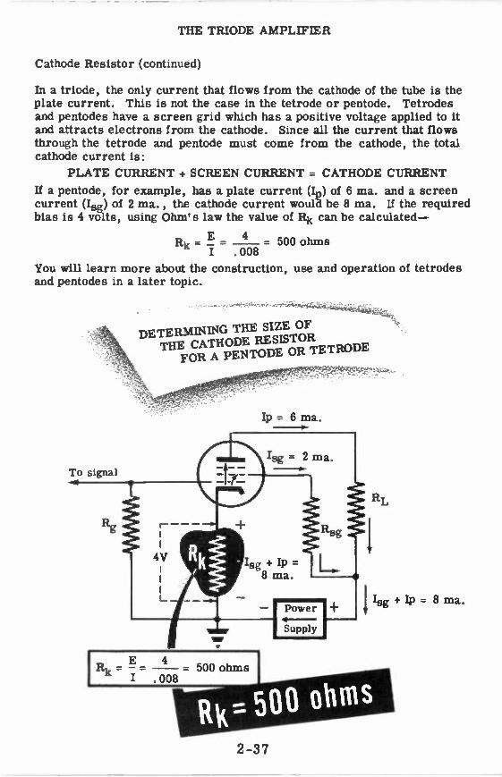
In a triode, the only current that flows from the cathode of the tube is the plate current. This is not the case in the tetrode or pentode. Tetrodes and pentodes have a screen grid which has a positive voltage applied to it and attracts electrons from the cathode. Since all the current that flows through the tetrode and pentode must come from the cathode, the total cathode current is:
PLATE CURRENT + SCREEN CURRENT = CATHODE CURRENT
If a pentode, for example, has a plate current (In) of 6 ma. and a screen current (Isg ) of 2 ma., the cathode current would be 8 ma. If the required bias is 4 volts, using Ohm's law the value of Rk can be calculated -
4 Rk = _ = 500 ohms
I .008
You will learn more about the construction, use and operation of tetrodes and pentodes in a later topic.
Ip = 6 ma.
To signal
-0?4oNtof,i4tudc,.,
DETER:VI NING THE SIZE OF THE CATHODE RESLSTOR
FOR A PENTODE OR TETRODE
Isg + Ip --8 ma.
- 500 ohms
Power 4 -Supply
Isg + Ip = 8 ma.
2-37

THE TRIODE AMPLIFIER
Cathode Bypass Capacitor
A cathode bias resistor usually has a capacitor connected in parallel with it. This capacitor is called a bypass capacitor and its purpose is to keep the voltage across the cathode resistor at a constant value.
Suppose we look at the operation of a triode using cathode bias with no by-pass capacitor. If a signal is applied to grid, the plate current will vary in accordance with the signal. Since it is the plate current flow through the cathode resistor that produces the bias, and this current flow varies,
the bias will also vary.
This varying bias reduces the signal voltage between grid and cathode. On the next sheet you will see how this signal reduction occurs.
To sIgnal
Rk
B -
•g•
Power
Supply
TRIODE AMPLIFIER WITH A CATHODE BYPASS CAPACITOR
1RIODE AMPLIFIER WITHOUT A CATHODE BYPASS CAPACITOR
2 -38

THE TRIODE AMPLIFIER
Cathode Bypass Capacitor (continued)
In the illustration below, an AC signal with a peak amplitude of 6V is ap-plied to the grid of the triode. The triode has a cathode bias voltage of -8V with no signal applied. If the bias voltage remained constant, the sig-nal would add to the bias during its negative half cycle, (8 + 6) = 14V neg-ative, and it would subtract from the bias during the positive half cycle (8 -6) = 2V negative.
With the grid to cathode voltage varying between -14V and -2V, the plate current will be minimum at -14V and maximum at -2V. In this case, as-sume that the plate current variation produces a voltage variation of 2 volts across the cathode resistor. Observe that the cathode voltage increases (becomes more negative) when the plate current increases and therefore the cathode bias voltage increases when the signal is reducing it (making it less negative). The voltage variation across the cathode resistor is 180 degrees out of phase with the input signal so that the two voltages (sig-nal and cathode voltage variation) subtract from one another to produce an effective voltage variation of (6 -2) = 4 volts between grid and cathode.
EG VOLTS
-2
4
6
-10
-12
-14
Applied signal = 6V
THE EFFECT OF CATHODE VOLTAGE VARIATION
Cathode voltage variation = 2V
j: Resultant grid to cathode variation = 6-2= 4V
_ _1
WNVYv
+6 ,
Signal Input
Min. ha
at -14f1
Max. P at -2V
Zero Signal
0
-6 B- "! -8
-10 - Cathode Voltage Variation
Cathode
2-39

THE TRIODE AMPLIFIER
Cathode Bypass Capacitor (continued)
In other words, the cathode voltage variations cancelled 2 volts of signal. This effect is called degeneration. To eliminate the effect of degeneration, a cathode bypass capacitor is placed in parallel with the cathode resistor. If the proper capacitance is chosen, its capacitive reactanc yfound by
using the formula you learned in Basic Electricity — Xc - 27rfC) will be
about one tenth the size of the resistor. Since a capacitor will only pass a continuously changing (AC) current, the steady (DC) component of cur-rent flows through the resistor and the varying component of current flows through the bypass capacitor. The resistor is virtually shorted out by the low reactance of the capacitor when a current variation occurs. The only current through the resistor is a steady one. Therefore, the voltage across the resistor will remain constant when a signal is applied to the grid and no signal cancellation will take place.
Here is an example of the method used to determine the size of the bypass capacitor. Suppose you had the circuit shown below.
1 RL
B+
1 Since Xc - 271C' the capacity of the bypass condenser can be found by
using the formula C = 2_1rx , where f is the lowest frequency signal to be c
amplified. Suppose f is 60 cps and Xc is 4000as shown above, then C
will be - 1 6.6 mfd.
6.28 x 60 x 400
Since capacitors are not made with a value of 6.6 mfd., a 10 mfd. ca-pacitor would be used.
2-40

THE TRIODE AMPLIFIER
Review of Triode Amplifier Operation
GRID BIAS — The amount of grid-bias voltage determines whether an ampli-fier is operating Class A, Class B or Class C. In Class A the bias is less than cut-off; in Class B bias is at or near cut-off; in Class C bias is much less than cut-off.
No plate current flowing
B+ POWER SUPPLY BIAS — A single power supply can be used to supply a positive voltage for B+ and a negative voltage for grid bias.
CATHODE BIAS — A cathode bias re-sistor in parallel with a cathode by-pass capacitor in the cathode circuit provide the most widely used system of biasing.
TRIODE AMPLIFIER OPERATION — The variation in voltage output (plate voltage) of a triode, used as an ampli-fier, may be ten or more times larger than the variation in the grid voltage (AC signal).
Linear portion
of curve
12
INPUT OUTPUT
2-41

THE TETRODE AND THE PENTODE
Why the Tetrode Was Developed
A capacitor, as you know, is nothing more than two pieces of metal separated by a dielectric (insulator). In a vacuum tube each pair of elements acts as if it were a small capacitor. In a triode there are three such capacitors —one consisting of the grid and plate, one of the grid and cathode and the third of the plate and cathode. These are called the"interelectrode capacitances"and each one has a capacitance of only a few micromicrofarads.
Grid-to-Cathode Capacitance
Plate-to-Cathode Capacitance
Grid-to-Plate Capacitance
The grid-to-plate capacitance is the one which causes most of the trouble. At high frequencies it produces undesirable effects which may prevent the tube from amplifying properly. This will be explained later.
The tetrode was developed to reduce the interelectrode capacitance be-tween the control grid and the plate.
2-42
THE TETRODE AND THE PENTODE
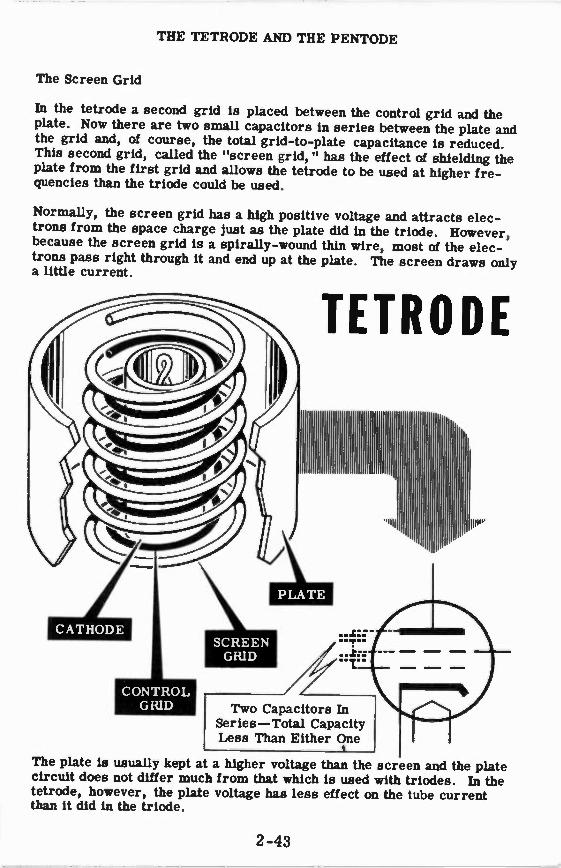
The Screen Grid
In the tetrode a second grid is placed between the control grid and the plate. Now there are two small capacitors in series between the plate and the grid and, of course, the total grid-to-plate capacitance is reduced. This second grid, called the "screen grid," has the effect of shielding the plate from the first grid and allows the tetrode to be used at higher fre-quencies than the triode could be used.
Normally, the screen grid has a high positive voltage and attracts elec-trons from the space charge just as the plate did in the triode. However, because the screen grid is a spirally-wound thin wire, most of the elec-trons pass right through it and end up at the plate. The screen draws only a little current.
TETRODE
PP"
Two Capacitors In Series —Total Capacity Less Than Either One
t
The plate is usually kept at a higher voltage than the screen and the plate circuit does not differ much from that which is used with triodes. In the tetrode, however, the plate voltage has less effect on the tube current than it did in the triode.
2-43

THE TETRODE AND THE PENTODE
Secondary Emission in the Tetrode
In any tube —diode, triode or tetrode —when one electron strikes the plate, it knocks several electrons out. Known as "secondary emission," this happens because the electrons are hitting the plate at high speed which be-comes ever greater as the plate voltage is raised.
In the triode, secondary emission is not important since the plate is the most positive element in the tube and, therefore, attracts all the electrons that have been knocked out of it. In the tetrode, however, some of these secondary electrons (those which have been freed from the plate as a re-sult of secondary emission) are attracted to the screen. Any flow of sec-ondary electrons from the plate to the screen adds to the screen current and subtracts from the plate current.
ear-away Seetioit - - OF A TETRODE The number of secondary electrons which do not return to the plate de-pends upon the difference between the plate and the screen voltages. li the plate voltage is much higher than the screen's, all the secondary elec-trons will return to the plate and there will be no decrease in plate current. If the plate voltage is much lower than the screen's, fewer secondary elec-trons will be emitted, but all of these will be attracted to the screen.
2-44

THE TETRODE AND THE PENTODE
Static Characteristics of the Tetrode
The tetrode is rarely used today, and you are being told about this tube only because it is a "stepping stone" between the triode and the pentode. If static characteristics of a tetrode were taken with varying plate voltage but constant control and screen grid voltages, you would get a curve re-sembling the one in the diagram.
X X
Fixed / screen grid voltage
Varying plate
voltages
Notice that at high plate voltages above 300V, the plate current does not change when the plate voltage is increased. This is because the screen shields the plate from the space charge at the cathode which causes the screen to exert a greater control over plate current than the plate itself.
At about 100 volts, an increase in plate voltage causes a decrease in plate current because more electrons are knocked out of the plate by secondary emission. As long as the plate voltage is below the screen voltage, almost all the secondary electrons go to the screen.
Plate Milliamps
20
15
10
5
0
Screen Voltage
-..-
= Grid Voltage -5V
f il
100 200 300 400 500 60 0
Plate Voltage
2-45

THE TETRODE AND THE PENTODE
Normal Operation of the Tetrode
Cathode bias in the tetrode is obtained in the same way as in the triode, except that in the tetrode the current flowing through the cathode resistor is the sum of the screen and plate currents.
The control grid voltage varies according to the input signal and produces variations in the plate current. Therefore the plate current the screen grid current vary with the control grid voltage. Screen grid voltage vari-ation is prevented by connecting a screen bypass capacitor to ground. This keeps the screen at a fixed DC level and the tube current will be varied only by varying the control grid voltage.
rE-1-•
AC Input I I--
-7MW-•
i INEr 11 MI MIP IIINV
1 =V III MP \M I v. V V
C Output
Z I ; 13 +
With AC on the control grid of the tube, the plate voltage will vary because of the drop in the load resistor just as in the triode. When the tetrode is used for getting large amplifications, the plate voltage varies over a wide range and, if it drops below the screen grid voltage, secondary emission effects cause distortion in the output.
To prevent this, the plate voltage would have to be very large to keep the plate at a higher potential than the screen regardless of the amount of voltage variation at the plate.
This —the requirement of an abnormally high B+ —is the main disadvantage of using a tet-rode. You will see how the pentode over-comes this disadvantage.
DISTORTED OUTPUT OF TETRODE WITH "LOW"
PLATE VOLTAGE SUPPLY
2-46

THE TETRODE AND THE PENTODE
Eliminating the Effects of Secondary Emission
You have seen that the main disadvantage of the tetrode is the need for a high plate voltage to prevent distortion in its output due to the effect of secondary emission.
The pentode is designed to overcome this undesirable feature of the tetrode by eliminating the flow of secondary electrons between the plate and the screen grid. This is accomplished by the inclusion of a third grid, the suppressor grid, between the plate and the screen grid.
earawaii Se etioa - - OF A PENTODE The suppressor grid is usually kept at cathode potential so that it is always very negative with respect r.o the plate. Therefore, any electron that is in the region between the suppressor and the plate (such as a secondary elec-tron) is attracted back to the plate and prevented from getting through the suppressor to the screen. As a result of this arrangement, secondary emission does not affect the operation of the pentode.
2-47

THE TETRODE AND THE PENTODE
How the Pentode Works
You remember that in a triode a decrease of the negative grid voltage pro-duced an increase in the current and a decrease in the plate voltage. The plate voltage change was more than the change in grid voltage. We called the ratio of plate voltage change to grid voltage change "amplification."
You remember too that the plate voltage in a triode also affects the current flow. The decrease in plate voltage has a tendency to decrease the current. The grid is trying to increase the current. It is clear, then, that the de-crease in plate voltage is opposing the effect of the grid voltage decrease.
If the grid has 20 times as much control of the current as the plate has, the limit of amplification would be 20. When such an amplification is reached, the plate voltage changes would be 20 times as large as the grid voltage changes and, theoretically, there would be no change in the current. Thus the amplification is limited by the fact that the plate has some effect or the current.
In a pentode, neither the suppressor nor the plate voltage affect the amount of current drawn from the space charge surrounding the cathode since the screen grid shields both of these elements from the cathode. As in the tetrode, the pentode's screen voltage is fixed at some positive value and, therefore, only the variations of control grid voltage cause changes in plate current.
1. When grid voltage in-
creases, current increases
TRIODE 4#ftedfriT asIV A #C4 4.0g
2. Plate voltage decreases and tends to decrease
current
3. When grid voltage in-
creases, current increases
4. Plate voltage decreases, but does not tend to decrease current
PENTODE gide& avez a 6icatiog
In the pentode the plate voltage can vary considerably with almost no effect on the current and, therefore, with no cancellation of the grid's control of the plate current. As a result, the amplification of a pentode is many times greater than that of a triode.
2-48

THE TETRODE AND THE PENTODE
A Typical Pentode Tube
_
Control Grid
Screen Grid
Suppressor Grid
Cathode
Heater
Wiring connections to the base
Anode or Plate
Suppressor Grid
Screen Grid
Control Grid
Cathode
Heater
2-49
THE TETRODE AND THE PENTODE
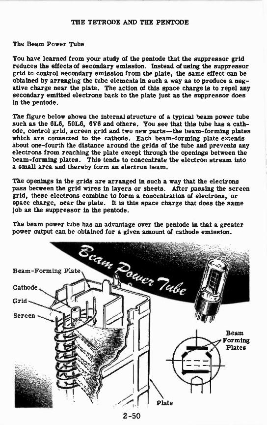
The Beam Power Tube
You have learned from your study of the pentode that the suppressor grid reduces the effects of secondary emission. Instead diming the suppressor grid to control secondary emission from the plate, the same effect can be obtained by arranging the tube elements in such a way as to produce a neg-ative charge near the plate. The action of this space charge is to repel any secondary emitted electrons back to the plate just as the suppressor does in the pentode.
The figure below shows the internal structure of a typical beam power tube such as the 6L6, 50L6, 6V6 and others. You see that this tube has a cath-ode, control grid, screen grid and two new parts —the beam-forming plates which are connected to the cathode. Each beam-forming plate extends about one-fourth the distance around the grids of the tube and prevents any electrons from reaching the plate except through the openings between the beam-forming plates. This tends to concentrate the electron stream into a small area and thereby form an electron beam.
The openings in the grids are arranged in such a way that the electrons pass between the grid wires in layers or sheets. After passing the screen grid, these electrons combine to form a concentration of electrons, or space charge, near the plate. It is this space charge that does the same job as the suppressor in the pentode.
The beam power tube has an advantage over the pentode in that a greater power output can be obtained for a given amount of cathode emission.
Beam-Forming Plate
Cathode
Grid
Screen
Beam Forming Plates
2-50

THE TETRODE AND THE PENTODE
The Beam Power Tube (continued)
Anode or Plate
Control Grid
Screen Grid
Beam-Forming Plate
Cathode
Heater
Wiring connections to the base
Anode or Plate
Beam-Forming Plates
Screen Grid
Control Grid
2-51

THE TETRODE AND THE PENTODE
Summary of Pentode Operation
4 Screen Voltage
1̀11111V
Voltage = -3V-
0 50 100 150 200 250 300 Plate Voltage
Curve No. 1: Over a wide range of plate voltages, the pentode plate current does not vary. But this is not saturation; in the next curve you will see that it is possible to draw more current than this. The reason the current doesn't vary over this range of values is that the screen shields the plate from the cathode's space charge.
At low plate voltages, however, the plate current does vary. Although the total tube current remains the same, many more electrons are attracted to the screen, which is now more positive than the plate is.
Curve No. 2: Here, you see that the control grid in a pentode controls current in the same way as it did in a triode. Nor-mal grid bias for this particu-lar pentode is about -3 volts.
The fact that the current rises considerably above 3 ma. in this test shows that 3 ma. is not the limit of cathode emission. Therefore, the flattened portion you saw in the first curve could not have been saturation.
12
Plate Current
10
8
6
4
2
0 8 6 4 -3 -2 0
2-52 Grid Voltage

THE TETRODE AND THE PENTODE
Summary of Pentode Operation (continued)
Curves No. 3 and 4: With the same value of load resistor in each, you can
obtain larger amplifications with the pentode than with the triode.
400
300
ca
200 a)
100
0 -20 -15 -10 -5 0
Grid Volts
W.th a larger load resistor in the pentode circuit, larger amplification is obtained. This happens because the grid voltage, and only the grid voltage, can produce a change of current. This current will flow through the load resistor —the larger the resistor, the larger the voltage change.
400
300
4 , 200
c ▪ d
100
0
-20 -15 -10 -5
Grid Volts
0
Compare the Changes in Plate Volts
Change in Grid Volts
2-53

THE TETRODE AND THE PENTODE
Review of Tetrodes and Pentodes
THE TETRODE — A tube having a screen grid to reduce plate-to-control grid capacitance. It is rarely used to-day, but was a step in the development of the pentode.
THE PENTODE — A tube which uses a suppressor grid between the screen grid and plate to reduce the effect of secondary emission. It has greater amplification than the triode.
THE BEAM POWER TUBE — Tube using beam-forming plates instead of the suppressor to reduce the effects of secondary emission. Its power out-put is greater, for a given amount of cathode emission, than that of a pentode.
PENTODE CIRCUIT — A circuit pro-viding proper operating voltages for control grid, screen grid and sup-pressor grid.
2-54

THE SINGLE-STAGE AMPLIFIER
A Typical Amplifier Stage
You are already familiar with the purposes of most of the components that will be used in this amplifier circuit. The 1-meg. resistor in the grid cir-cuit is there to prevent any negative charge from accumulating on the grid. The 12K resistor and the 25-mfd, capacitor in the cathode circuit are the bias components. The 270K resistor in the plate circuit is the load re-sistor. The .01-mfd. capacitor and the 1-meg. resistor will be the RC coupling to the next stage of amplification.
3
INPUT 5
I MEG 12 K
6C5 .01 TOD
8 270 K
IMP
25MFD
8+
OUTPUT
TYPICAL AMPLIFIER STAGE
The circuit shown below has two additional components. You will notice that the plate load resistor is connected toB+ through a 25K resistor. This resistor and the 8-mid. capacitor make up a special filter circuit called a decoupling filter. If some form of undesired coupling exists between the various circuits of a multistage amplifier, we say that we have feedback. This feedback causes the amplifier to generate a low frequency audio sig-nal which sounds like a motorboat when heard from the loudspeaker. It is the job of the decoupling filter to eliminate the feedback and the resultant motorboating.
Typical Amplifier Stage with DECOUPLING FILTER
INPUT
I MEG 12 K
3
EC5 .01 MFD
25MFD INFO
El+
2 -55
270K
OUTPUT

THE SINGLE-STAGE AMPLIFIER
The Decoupling Filter
Coupling may exist between circuits operating at the same frequency and having common impedance. If an amplifier contains several stages of am-plification, all those stages will be supplied with plate voltage from a single source of DC power. The plate currents of all the amplifier tubes must flow through this power supply. Therefore, the internal resistance of the power supply (produced by the choke wire, internal tube resistance, etc.), will act as a common impedance for all the amplifier circuits.
When a signal is applied to the amplifier, the plate currents of all the tubes will vary in accordance with the signal. In addition to the DC flowing through the common power supply, we now have the AC components of all the plate currents flowing through the common impedance. Some of these currents will be in phase with each other and some will be 180 de-grees out of phase. It is the currents which are in phase that cause the most trouble.
The in-phase currents add to one another and produce voltage variations across the common impedance which "feeds back" the variations from one stage to another. The overall effect of this is a sound in the loudspeaker which resembles the purring of an outboard motor. That is why this trou-ble in an amplifier is called "motorboating."
On the next sheet you will see how the decoupling filter eliminates feed-back and motorboating.
FEEDBACK IN A THREE STAGE AMPLIFIER
Signal voltage
IMP
Plate current
RL
T
Plate current
Feedback from last 1,1 stage
IMP
1Power :I: . Supply .. .‘" ''•
l Common Impedance i
, Plate current
2-56

THE SINGLE-STAGE AMPLIFIER
The Decoupling Filter (continued)
If the AC components of plate current could be kept from flowing through the common impedance of the power supply, then the feedback that origin-ates there would be eliminated. The decoupling filter's job is to provide a path of low reactance around the power supply and a path of high resist-ance to AC current flow through the power supply. Because of this very little AC current will flow through the power supply and its common im-pedance, thereby eliminating feedback.
The value of the decoupling capacitor must be high enough so that its re-actance is much less than the total resistance of the decoupling resistor and the common impedance of the power supply. In an amplifier of the type shown, the value of the decoupling resistor is generally about one fifth the value of the plate load resistor RL. The value of the decoupling capaci-tor varies from about 0.25 to 8 mfd.
The action of the decoupling filter is to isolate each stage from the power supply common impedance. The way the filter does this is shown below.
-Deeztaiiii#1 7aterd, ISOLATE AMPLIFIER
STAGES AND ELIMINATE FEEDBACK
•■•
. .....
Decoupling Filter I Power. Supply
::•
Flow of AC component of plate current
Common Impedance
'IC
Decoupling Filter
2-57

THE TWO-STAGE RC COUPLED AMPLIFIER
How to Increase Gain
If you need a voltage gain of 200 or less in an amplifier, one tube would be enough. However, very often a gain of 10,000 or 100,000 or even higher is required, and there is no way to make a single vacuum tube give you that much amplification. In order to increase the amplification, several tubes are needed.
These tubes are connected so that the voltage change from the plate of one amplifier tube is fed into the grid of a second tube; the voltage change from the plate of the second tube is fed into the grid of a third tube and so forth. If the amplification of each tube is 50, the signal input to the second tube will be 50 times greater than the signal fed into the first. The output of the second tube will be 50 times greater than its input or 2,500 times greater than the original signal. The third tube will amplify the output of the second tube 50 times so that its output is 50 x 2,500 times larger than the input to the first tube. Thus, the amplifier using three tubes, each with a gain of 50, has an overall gain of 125,0001
50 x 50 x 50 = 125,000
If the voltage change applied to the input of this amplifier is one ten-thousandth of a volt, the voltage change on the plate of the third tube will be twelve and a half volts.
/4 A
Amplifier
NO. 1
X 50
•NIN,
Amplifier
NO. 2
X 50 fv\, Amplifier
NO. 3
X 50
INPUT OUTPUT
1 1 I 1 10,000 I 200 4 12 1/2
1 VOLTS 1 VOLTS I iVOLTSI I VOLTS
I I I i
Since nearly all amplifiers require more amplification (gain) than can be achieved with only one tube, multi-stage amplifiers of this type are very common in all types of electronic equipment.
2-58

THE TWO-STAGE RC COUPLED AMPLIFIER
Coupling of Amplifier Stages
When several tubes are used in an amplifier, each tube together with its circuit is called a "stage.' of amplification. There are several methods of connecting the output of one stage to the input of the next stage. You re-member that the output of an amplifier tube is taken from the plate and the input is placed on the grid. Since the DC operating voltages of a plate and of a grid are so very different, a simple wire leading from one plate to the next grid cannot be used. The connection (or "coupling" as it is more com-monly called) between two stages must, in some way, prevent the DC plate voltage from getting to the next grid. At the same time, the coupling must permit the plate voltage variations —AC —to become the input of the next stage.
There are two very common and very simple ways of doing this. One way is by using a transformer, the other by using a capacitor and a resistor.
Transformer coupling is accomplished by connecting the primary winding between the plate of the first tube and B+, and the secondary winding be-tween the grid of the second tube and ground. By so doing, the B+ voltage is isolated in the plate circuit while only the AC is transferred to the grid.
B+ .
TRANSFORMER COUPLING
The use of the capacitor in coupling circuits is very widespread, the most common circuit being the RC (or resistance-capacitor) circuit, In your study of vacuum tubes, you learned that current variations in the load re-sistor cause the voltage at the plate to vary above and below a steady value. The coupling capacitor will charge to that steady voltage and, as the plate voltage rises above and falls below that value, the capacitor will charge and discharge slightly, causing an AC current to flow in the grid re-sistor. The voltage across the grid resistor therefore is AC and is the input to the next stage.
a,. Coupling Capacitor
B+
Plate Load
Resistor
RC COUPLING
2-59

THE TWO-STAGE RC COUPLED AMPLIFIER
Characteristics of the Two-Stage Amplifier
The two-stage amplifier can be compared to two step-up transformers with the secondary of one connected to the primary of the other. For ex-ample, if two transformers which have a step-up ratio of 1 to 3 are con-nected in this manner, an AC voltage applied to the primary of the first transformer would be amplified 9 times by the combination. This example is illustrated below.
OBTAINING VOLTAGE AMPLIFICATION WITH A TRANSFORMER AND VACUUM AMPLIFIER
1 to 3
•
1 to 9 1 to 3
9V
You may conclude from this that it would be a good idea to forget all about using vacuum tubes as amplifiers and use transformers instead. This is not possible because transformers with very high step up ratios would have to be used if they were to deliver a high amplification. Transformers of this type are impractical and even if they were used would not amplify all the audio frequencies the same amount. The higher audio frequencies (around 10,000 cycles) and the lower audio frequencies (around 100 cycles) would not be amplified as much as the middle frequencies. This would re-sult in a signal output that is not a true representation of the original sig-nal applied to the transformers.
Amplifiers using vacuum tubes can deliver much higher amounts of ampli-fication, are lighter in weight, less costly and take up less space. On the next sheet you will see how a multistage vacuum tube amplifier compares to the transformer combination explained here.
2-60

THE TWO-STAGE RC COUPLED AMPLIFIER
Characteristics of the Two-Stage Amplifier (continued)
When the output of one amplifier is fed to the input of another, the two am-plifiers are said to be connected in cascade. An amplifier arrangement of this type is shown below.
I VOLTAGE AMPLIFICATION IN A TWO-STAGE AMPLIFIER
Suppose each amplifier stage can deliver an amplification of 20. If a 0.1 volt AC signal is applied to the grid of the first stage, the output of this stage will be 20 x 0.1 = 2V. Since the output of the first stage is connected to the input of the next stage there will be 2 volts AC on the grid of the second stage. The second stage amplifies the signal 20 times and pro-duces an output voltage of 20 x 2 = 40V.
The overall amplification of the two stages is the product of the individual amplifications, that is, the gain of the first stage x the gain of the second stage. In this case the overall amplification is 20 x 20 = 400. You can check this by multiplying the input voltage of 0.1 volts by the overall am-plification. The result will be the output voltage (400 x 0.1 = 40V).
If another stage is added to the output of the two-stage amplifier, 40 volts would be applied to its grid. In most cases, this signal would be too large for the tube to handle. The result is that the grid would be driven into the positive region and the cut-off region, and distortion produced. A poten-tiometer in the grid circuit of one of the amplifier tubes could be used to reduce the output signal so that the following stages would not be over-driven. This potentiometer is commonly referred to as the volume control.
VOLUME CONTROL IN A TWO-STAGE AMPLIFIER
2-61

THE TWO-STAGE RC COUPLED AMPLIFIER
Frequency Response
Frequency response is a term applied to describe the effect in which some frequencies are amplified more than others. In actual practice, all ampli-fiers have a range over which they are designed to operate; above and be-low this range the signal output drops off rapidly. If an audio amplifier cannot amplify all the frequencies of the human voice by an equal amount, there is a loss of voice quality.
FREQUENCY RANGES —
MUSICAL INSTRUMENTS
HUMAN VOICE
Range of Good Radio Sets
Range of "Tinny" Radio Sets — P
11 Piccolo
Trumpet
Bass Tuba
Violin
Cello
Soprano
Alto
Tenor
Baritone
Bass
III III ill II 11 11 III II
It is possible for this frequency distortion to be so great that the voice message cannot be understood. For this reason you should learn to meas-ure the frequency response of your amplifier and see how good it actually is. A modern commercial amplifier designed for music amplification will have an equal gain from 30 - 15,000 cycles. A range as wide as this is hardly necessary for good amplification of voice signals.
2-62

THE TWO-STAGE RC COUPLED AMPLIFIER
Frequency Response (continued)
Even though the RC-coupled amplifier is well suited for the job of ampli-fying a wide range of frequencies, there are still causes for a drop in gain at high and low frequencies. Let's take a quick look at these causes:
At low frequencies the coupling capacitor and the grid resistor make up a voltage divider across the signal voltage input. As a result, only part of the signal gets to the grid of the amplifier tube. Just how much of the signal gets to the grid depends upon the reactance of the coupling capaci-tor as compared to the resistance of the grid resistor.
COUPLING I CAPACITOR
GRID RESISTOR
1 Due to the fact that capacitive reactance M c - aw iC• grows larger as fre-
quency decreases, the amount of signal voltage lost across the capacitor increases at low frequencies. You can see that the signal voltage across the grid resistor becomes less and less as the frequency decreases. To reduce this loss of signal, the reactance of the coupling capacitor should be small with respect to the grid resistor at the lowest frequency to be amplified. This means that either the grid resistor or the coupling capac-itor should be as large as possible. (If C increases, Xc decreases.)
However, if the coupling capacitor is made too large, there will be in-creased leakage through it from Bi-. This leakage will place a positive voltage on the grid and thereby disturb the amplifier operation. Luckily, we never need coupling capacitors that are so large that leakage be-comes a problem. In fact, because of size and weight considerations, it is common to use a smaller coupling capacitor than is needed. Thus, low frequency response is sacrificed slightly so as not to bring about more serious problems. At high frequencies the coupling capacitor is no longer a cause of trouble, since its reactance is low compared to the grid leak resistor.
WITH 10 VOLTS INPUT
1-- --- -----. .. About
2 volts ...-------- - -""-------
...„„w„....,,, - d About
8 volts volts 10
About
LOW FREQUENCY
2-63
MEDIUM FREQUENCY
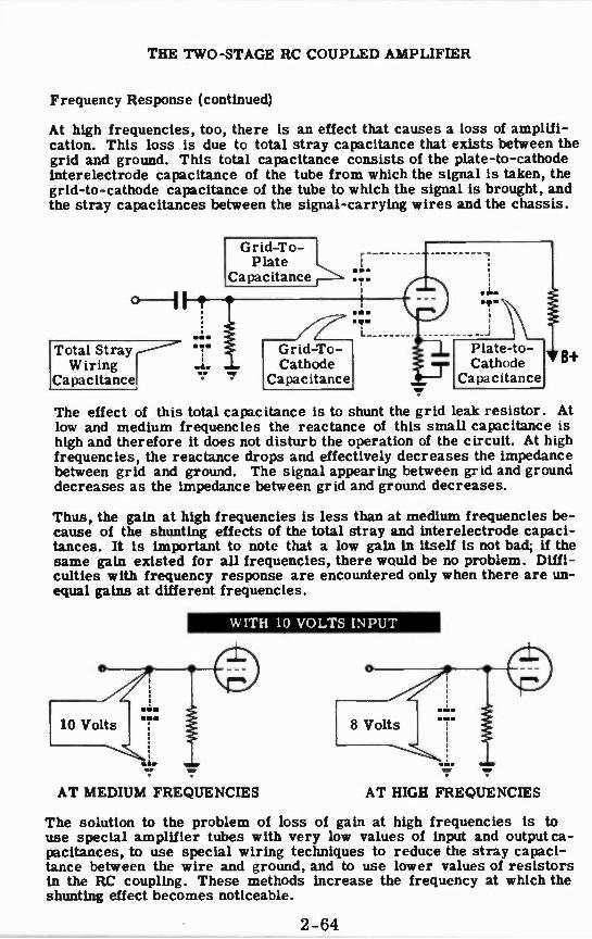
THE TWO-STAGE RC COUPLED AMPLIFIER
Frequency Response (continued)
At high frequencies, too, there is an effect that causes a loss of amplifi-cation. This loss is due to total stray capacitance that exists between the grid and ground. This total capacitance consists of the plate-to-cathode interelectrode capacitance of the tube from which the signal is taken, the grid-to-cathode capacitance of the tube to which the signal is brought, and the stray capacitances between the signal-carrying wires and the chassis.
Grid-To-Plate ..
Capacitance • •..
Total Stray Wiring
Capacitance
•Ips
Grid-To-Cathode
Capacitance
Plate-to-Cathode
Capacitance
The effect of this total capacitance is to shunt the grid leak resistor. At low and medium frequencies the reactance of this small capacitance is high and therefore it does not disturb the operation of the circuit. At high frequencies, the reactance drops and effectively decreases the impedance between grid and ground. The signal appearing between grid and ground decreases as the impedance between grid and ground decreases.
Thus, the gain at high frequencies is less than at medium frequencies be-cause of the shunting effects of the total stray and interelectrode capaci-tances. It is important to note that a low gain in itself is not bad; if the same gain existed for all frequencies, there would be no problem. Diffi-culties with frequency response are encountered only when there are us-equal gains at different frequencies.
WITH 10 VOLTS INPUT
ID • •••
AT MEDIUM FREQUENCIES AT HIGH FREQUENCIES
The solution to the problem of loss of gain at high frequencies is to use special amplifier tubes with very low values of input and output ca-pacitances, to use special wiring techniques to reduce the stray capaci-tance between the wire and ground, and to use lower values of resistors in the RC coupling. These methods increase the frequency at which the shunting effect becomes noticeable.
2-64

THE TWO-STAGE RC COUPLED AMPLIFIER
The Frequency Response Curve
The usual way that the frequency response of an amplifier is shown is with a frequency response curve. In this curve, a plot is made of the gain at each frequency; the highest gain is 100 percent (or sometimes 1.00) and any gain below that is figured as a certain percent of maximum —such as 75 percent, 25 percent, and so forth.
100%r L
I
70% POINTS
USABLE RANGE
tr-
1 100 200 5,000 10,000 115,000 FREQUENCY (CPS)
The general shape of the curve shows a flat region (plateau) between the ends of the curve. This means that the gain does not vary by very much as the frequency changes from the low end to the high end of this portion. This represents the usable frequency range of the amplifier.
On either side of this flat portion, there is a rapid falling-off of the curve. This means that the gains at these frequencies (both low and high)are not as high as the gain at the middle frequencies. In a speaker, the ear can detect these lowered gains if they are about 70 percent of maximum or be-low. Therefore, it is the 70-percent points on each end of the curve that determine the usable range.
As you remember from the previous discussions on frequency response, the reason for the decreased gain at the low end of the band was the fact that the coupling capacitor and the grid leak resistor form a voltage divider. The reactance of the coupling capacitor increases at the low fre-quencies, and the voltage across the resistor decreases. At the high end, the loss of gain is due to the shunting effect of the stray capacitances be-tween grid and ground. At the middle frequencies, neither effect is notice-able and the gain does not vary by any appreciable amount.
2-65

THE TWO-STAGE RC COUPLED AMPLIFIER
Review of the Two-Stage Amplifier
Coupling Capacitor
RC COUPLING — When two or more stages are used in an amplifier, the AC plate voltage of each stage is fed to the grid of the next stage through the coupling capacitor and resistors.
VOLTAGE GAIN — The total ampli-fication of a two-stage (or multistage) amplifier is the product of the am-plifications of each stage. The ratio of the output voltage of final stage to the input voltage of first stage is called the gain of the amplifier.
AMPLIFICATION LOSSES — At low frequencies the high reactance of the coupling capacitor reduces voltage gain; at high frequencies stray ca-pacitance causes loss of voltage gain.
FREQUENCY RESPONSE — A meas- LI" ure of the ability of an amplifier to - amplify AC signals of various fre-quencies by the same amount.
POZWII
USABLE RANCE
100 200 0000 10,000 I'Lige FREQUENCY (crs)
2-66
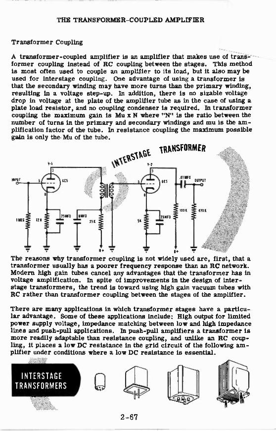
THE TRANSFORMER-COUPLED AMPLIFIER
Transformer Coupling
A transformer-coupled amplifier is an amplifier that makes use of trans-former coupling instead of RC coupling between the stages. This method is most often used to couple an amplifier to its load, but it also may be used for interstage coupling. One advantage of using a transformer is that the secondary winding may have more turns than the primary winding, resulting in a voltage step-up. In addition, there is no sizable voltage drop in voltage at the plate of the amplifier tube as in the case of using a plate load resistor, and no coupling condenser is required. In transformer coupling the maximum gain is Mu x N where "N" is the ratio between the number of turns in the primary and secondary windings and mu is the am-plification factor of the tube. In resistance coupling the maximum possible gain is only the. Mu of the tube.
INPUT 5
161T6 111(
P-I
3
6C5
MMO OWD
25A
5
"
5M
13
IRMiSFORMER
3
25MFO
B.
The reasons why transformer coupling is not widely used are, first, that a transformer usually has a poorer frequency response than an RC network. Modern high gain tubes cancel any advantages that the transformer has in voltage amplification. In spite of improvements in the design of inter-stage transformers, the trend is toward using high gain vacuum tubes with RC rather than transformer coupling between the stages of the amplifier.
.01 WEI OUTPUT
MON 4701{
There are many applications in which transformer stages have a particu-lar advantage. Some of these applications include: High output for limited power supply voltage, impedance matching between low and high impedance lines and push-pull applications. In push-pull amplifiers a transformer is more readily adaptable than resistance coupling, and unlike an RC coup-ling, it places a low DC resistance in the grid circuit of the following am-plifier under conditions where a low DC resistance is essential.
INTERSTAGE TRANSFORMERS
2-67

THE TRANSFORMER-COUPLED AMPLIFIER
Transformer Coupling (continued)
The main disadvantage of transformer coupling is that the impedance of the primary and secondary windings is not constant,but changes if the fre-quency of the signal is changed. If the frequency increases, the impedance increases and when the frequency decreases, the impedance decreases.
Look at the transformer in the schematic on the previous sheet. Suppose the primary winding has an inductance of 10 henries. At the low frequency of 100 cycles it will have an inductive reactance of—
XL = 27 fL = 6.28 x 100 x 10 = 6,280 ohms
At the mid-frequency of 1000 cycles, the inductive reactance will be —
XL = 2r fL = 6.28 x 1000 x 10 = 62,800 ohms
and at 10,000 cycles, it would be —
XL = 2r fL = 6.28 x 10,000 x 10 = 628,000 ohms
Since the inductive reactance of the primary is used as the plate load im-pedance of the triode amplifier, the inequality of reactance to AC signals of different frequencies will produce non-uniform amplification over the audio frequency range. A graph of the amplification of a transformer-coupled amplifier is shown below.Compare the graph of the transformer-coupled amplifier with that of the RC-coupled amplifier. Notice how much more uniform the amplification of the RC-coupled amplifier is.
THE AMPLIFICATION OF AN RC-COUPLED AMPLIFIER AND A TRANSFORMER-COUPLED AMPLIFIER AT AUDIO FREQUENCIES
30
25
Amplification 20
15
10
5 0
I I 111111
il.111111 r :ng In M N ‘lig
f I
Transformer Coupling
I I I fill' ‘ 100 1,000 10,000
Frequency in Cycles per Second
2 -68

THE TRANSFORMER-COUPLED AMPLIFIER
Characteristics of the Transformer-Coupled Amplifier
The transformer-coupled amplifier shown below is typical of most am-plifiers of this type. The amplifier has two stages coupled by an inter-stage audio transformer that has a 3 to 1 step-up ratio. The input stage uses a 6C5 triode V-1. The amplified output voltage of this tube is stepped up 3 times by the transformer and then fed to the grid of another 6C5 triode V-2. The second triode amplifies the signal still further and its amplified output appears across the 100K plate load resistor. The 0.01 mid coupling capacitor blocks the DC but presents a low reactance to the AC component at the plate of V-2. Therefore, only the AC component of the plate voltage at V-2 appears across the 470K resistor. Normally, the 470K resistor would be the grid resistor of the next stage so that the sig-nal across the resistor could be amplified further.
.0sV ORMER - COUPLED AMpLifo
On the next sheet, a signal will be traced through the transformer-coupled amplifier and you will see how amplification occurs in this circuit.
2-69

THE TRANSFORMER-COUPLED AMPLIFIER
Characteristics of the Transformer-Coupled Amplifier (continued)
The amplification that can be expected from a transformer-coupled ampli-fier stage is approximately equal to the amplification factor (it) of the tube times the turns ratio of the transformer (N). Amplification = p. x N. In this case, a 6C5 tube is used which has a iii of 20. The transformer has a step-up turns ratio of 3 to 1. Therefore, we can expect an amplification or gain of—fri. x N = 20 x 3 = 60.
Suppose a 0.01 volt AC signal is applied to the grid of V-1. From the illustration you can see that the output voltage of the 6C5 appears across the primary winding of the transformer and is amplified // times (20 x .01 = 0.2V). The transformer steps up the primary voltage 3 more times so that the secondary voltage is 3 x 0.2 = 0.6V.
It was stated that the gain of this stage is equal top N or 60. Let 1113 see if this checks. The grid signal is 0.01V. If we multiply this grid voltage by the gain we should get the voltage at the secondary of the trans-former, or 0.6V. Multiply 60 x 0.01 = 0.6V and you can see that this relationship holds.
VOLTAGE AMPLIFICATION IN A TRANSFORMER-COUPLED AMPLIFIER
The voltage across the secondary of the transformer (0.6V) is now applied to the grid of V-2. If we assume that the gain of V-2 is equal to/b, then V-2 will amplify this signal 20 times. Therefore, the output voltage at the plate of V-2 will be -20 x 0.6 = 12V.
The total gain is determined by multiplying the individual stage gains to-gether. The gain of V-1 and the transformer is 60 and the gain of V-2 is 20. The overall gain is-60 x 20 = 1200.
Checking this result, the input to V-1 times the overall gain should give us the output voltage of V-2 -1200 x 0.01 = 12V which is correct.
2-70

THE AUDIO POWER AMPLIFIER
Characteristics of Audio Power Amplifiers
Up to this time you have been learning about audio amplifiers that are pri-marily designed to amplify the signal voltage up to many times the origi-nal input voltage. Now you will learn about power amplifiers. In a voltage amplifier the varying signal current in the plate circuit is used only in the production of a voltage to be applied to the grid of a following stage. The plate current is usually relatively small.
On the other hand, a power amplifier must supply a heavy signal current into a load impedance which usually lies in the range of 2000 to 20,000 ohms. Power amplifiers are used to drive power-consuming circuits or devices, such as loudspeakers, certain portions of transmitters and large amplifier stages whose grids require power from the preceding stage.
One use of audio power amplifiers is, of course, to produce a powerful audio signal. The radioman will find it used as the output stage of his re-ceivers, and also in equipment which injects voice signals into transmitters. The sound man will find this circuit in almost every piece of his sound equip-ment. The sonarman will find audio power amplifiers used to produce the signal to drive not only a loudspeaker but also the underwater sound element called a transducer. Audio power amplifiers are also used in equipments which rotate radar antennas, sonar transducers and ship's guns.
POWER AMPLIFIERS
Are Used in Many Types of
Equipment
2-71

THE AUDIO POWER AMPLIFIER
Characteristics of Audio Power Amplifiers (continued)
You have learned in the preceding topics that the main purpose of voltage amplifier circuits is to produce a large increase in signal voltage. The amplified output of the voltage amplifier will now be applied to the grid of a power amplifier stage.
In the voltage amplifier circuits the output of one voltage amplifier is con-nected to the grid of the next stage. No current flows in this grid circuit, therefore no power will be consumed. If current did flow in the grid cir-cuit, the power loss in this circuit would have to be supplied by the pre-ceding stage. In the case of an amplifier that feeds a loudspeaker, the speaker requires large amounts of AC signal current for proper operation. When current flows in a circuit, power is always consumed. The power amplifier stage must supply the power that is consumed in the loud-speaker circuit.
The tubes used in voltage amplifier circuits are generally operated as Class A while the tubes used in power amplifier circuits may be operated either as Class A, Class B or Class AB.
Triodes, pentodes and beam power tubes can be used as power amplifiers. These tubes may be operated singly, in parallel, or in push-pull. The type of operation depends upon the amount of power required of the amplifier.
Voltage amplifiers are usually operated with a high value of plate load re-sistance or impedance to obtain the maximum voltage output. Pcwer am-plifier tubes are operated with lower values of load impedance to obtain a large current variation and a large power output. In a power amplifier, the amount of voltage output is not important for it is the power output which is the main factor.
If large amounts of power are to be supplied by the power amplifier, it must be capable of carrying high current —much more current than a volt-age amplifier.
AUDIO POWER AMPLIFIER
INPUT
11116
• • •
V-I
iC5
25 MIS
e6
c:31- el
$‘0"3' 041t2‘‘ 9°4i 40,•-• V-2
"
„Ccie•S
Signal power consumed
• •
2-72

THE AUDIO POWER AMPLIFIER
Characteristics of Audio Power Amplifiers (continued)
The current that flows through the plate circuit of the power amplifier tube is made up of two parts:
1. A steady or DC component 2. A varying or AC component
The useful part of the plate current is the varying component as only vari-ations in plate current produce sounds in the loudspeaker. The AC com-ponent of plate current flows through the primary of the output transformer along with the DC component. The DC component just produces a steady magnetic field about the primary winding and does not induce any voltage into the secondary. The AC component makes use of transformer action and induces a voltage into the secondary which is applied to the voice coil of the loudspeaker. This voltage is converted into sound by the loudspeaker.
You can see that the steady plate current does not contribute directly to-wards the sound output of the power amplifier circuit. This portion of the plate current does produce a power loss in the plate circuit which produces heating of the power amplifier tube and the output transformer.
AC AND DC CURRENTS
IN A POWER AMPLIFIER
II
2-73
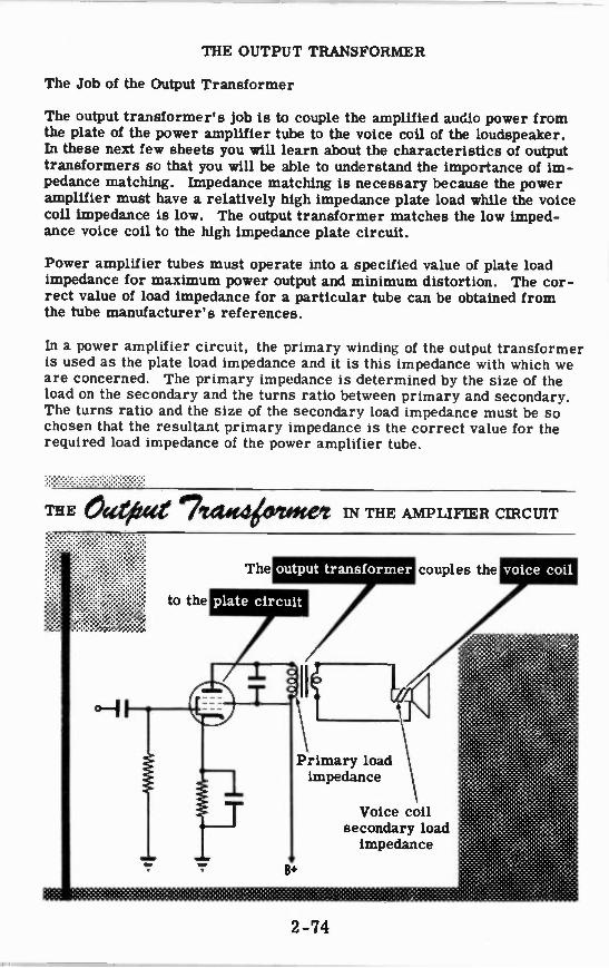
THE OUTPUT TRANSFORMER
The Job of the Output Transformer
The output transformer's job is to couple the amplified audio power from the plate of the power amplifier tube to the voice coil of the loudspeaker. In these next few sheets you will learn about the characteristics of output transformers so that you will be able to understand the importance of im-pedance matching. Impedance matching is necessary because the power amplifier must have a relatively high impedance plate load while the voice coil impedance is low. The output transformer matches the low imped-ance voice coil to the high impedance plate circuit.
Power amplifier tubes must operate into a specified value of plate load impedance for maximum power output and minimum distortion. The cor-rect value of load impedance for a particular tube can be obtained from the tube manufacturer's references.
In a power amplifier circuit, the primary winding of the output transformer is used as the plate load impedance and it is this impedance with which we are concerned. The primary impedance is determined by the size of the load on the secondary and the turns ratio between primary and secondary. The turns ratio and the size of the secondary load impedance must be so chosen that the resultant primary impedance is the correct value for the required load impedance of the power amplifier tube.
THE O atite al 7 IN THE AMPLIFIER CIRCUIT
2-74

THE OUTPUT TRANSFORMER
The Job of the Output Transformer (continued)
In a transformer there are two currents —the primary and secondary cur-rents. The current flow in the primary depends on the amount of current flow in the secondary. If the secondary current increases, then the pri-mary current will also increase. This can be explained by referring to Lenz's law, which states that the magnetic field produced by an induced current is always in opposition to the magnetic field that produced the in-duced current. In other words, the magnetic field produced by current flow in the secondary of a transformer is in opposition to, and cancels some of, the magnetic field produced by the primary winding. You now can see that if the secondary load impedance is decreased, the secondary current and magnetic field will increase and cancel a greater portion of the primary field. If some of the primary field is cancelled, then the in-ductive reactance and therefore the impedance of the primary will de-crease. By choosing the proper value of secondary impedance, we can obtain the desired primary load impedance for the power amplifier tube.
If the secondary load impedance cannot be changed —for example, the Primary turns
voice coil in a loudspeaker —the turns ratio -secondary turns can be varied
to obtain the proper primary impedance. This is done by using an output transformer with a tapped secondary.
Primary current Secondary current
2-75
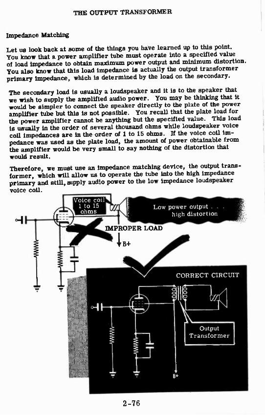
THE OUTPUT TRANSFORMER
Impedance Matching
Let us look back at some of the things you have learned up to this point. You know that a power amplifier tube must operate into a specified value of load impedance to obtain maximum power output and minimum distortion. You also know that this load impedance is actually the output transformer primary impedance, which is determined by the load on the secondary.
The secondary load is usually a loudspeaker and it is to the speaker that we wish to supply the amplified audio power. You may be thinking that it would be simpler to connect the speaker directly to the plate of the power amplifier tube but this is not possible. You recall that the plate load for the power amplifier cannot be anything but the specified value. This load is usually in the order of several thousand ohms while loudspeaker voice coil impedances are in the order of 1 to 15 ohms. If the voice coil im-pedance was used as the plate load, the amount of power obtainable from the amplifier would be very small to say nothing of the distortion that would result.
Therefore, we must use an impedance matching device, the output trans-former, which will allow us to operate the tube into the high impedance primary and still, supply audio power to the low impedance loudspeaker
voice coil.
Voice coil 1 to 15
4t. ohms Low power output . . .
high distortion
IMPROPER LOAD
1B+
CORRECT CIRCUIT
2 -76
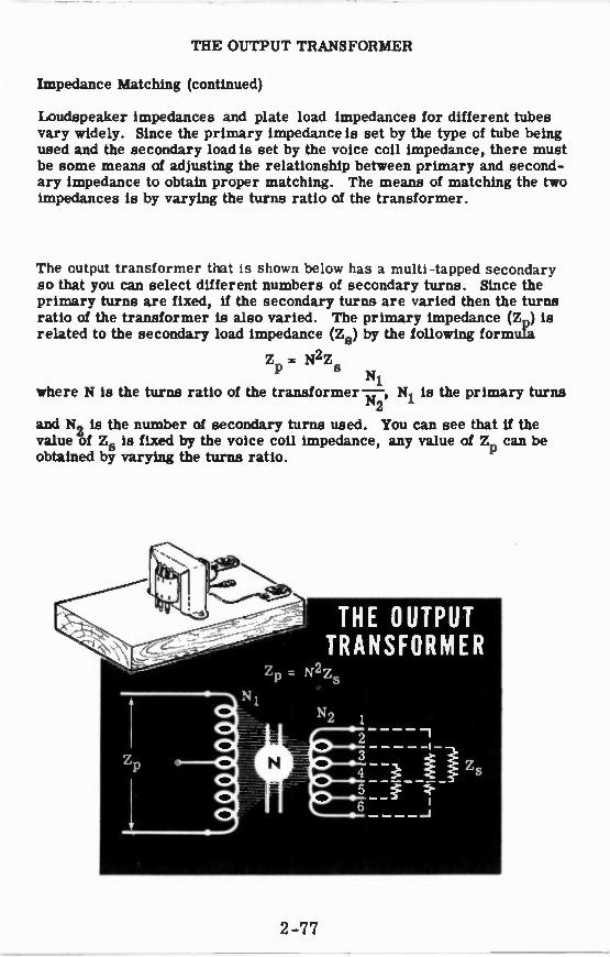
THE OUTPUT TRANSFORMER
Impedance Matching (continued)
Loudspeaker impedances and plate load impedances for different tubes vary widely. Since the primary impedance is set by the type of tube being used and the secondary load is set by the voice coil impedance, there must be some means of adjusting the relationship between primary and second-ary impedance to obtain proper matching. The means of matching the two impedances is by varying the turns ratio of the transformer.
The output transformer that is shown below has a multi-tapped secondary so that you can select different numbers of secondary turns. Since the primary turns are fixed, if the secondary turns are varied then the turns ratio of the transformer is also varied. The primary impedance (ZD) is related to the secondary load impedance (Zs) by the following formula
ZP = N2Z N1
where N is the turns ratio of the transformer — ' N is the primary turns 12 1
and N2 is the number of secondary turns used. You can see that if the value of Zs is fixed by the voice coil impedance, any value of Z can be obtained by varying the turns ratio.
2-77
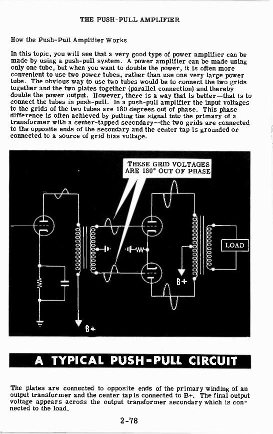
THE PUSH-PULL AMPLIFIER
How the Push-Pull Amplifier Works
In this topic, you will see that a very good type of power amplifier can be made by using a push-pull system. A power amplifier can be made using only one tube, but when you want to double the power, it is often more convenient to use two power tubes, rather than use one very large power tube. The obvious way to use two tubes would be to connect the two grids together and the two plates together (parallel connection) and thereby double the power output. However, there is a way that is better—that is to connect the tubes in push-pull. In a push-pull amplifier the input voltages to the grids of the two tubes are 180 degrees out of phase. This phase difference is often achieved by putting the signal into the primary of a transformer with a center-tapped secondary—the two grids are connected to the opposite ends of the secondary and the center tap is grounded or connected to a source of grid bias voltage.
A TYPICAL PUSH-PULL CIRCUIT
The plates are connected to opposite ends of the primary winding of an output transformer and the center tap is connected to B+. The final output voltage appears across the output transformer secondary which is con-nected to the load.
2-78

THE PUSH-PULL AMPLIFIER
How the Push-Pull Amplifier Works (continued)
In a typical push-pull amplifier, the grids receive AC voltages from oppo-site terminals of a transformer secondary winding. The transformer sec-ondary is center-tapped and the center tap is connected to ground. The AC grid voltages are 180 degrees out of phase. When one grid becomes less negative, the other grid becomes more negative by the same amount. The sum of the tube currents does not vary but remains pure DC since, when one current is increasing, the other is decreasing by the same amount. Because the sum of the two currents is pure DC, no bypass ca-pacitor is needed across the cathode bias resistor.
In the output transformer, it is the difference between the two currents that is the output signal. The greater the signal input, the greater this difference and the greater the output.
Below you see a set of typical wave forms taken from a push-pull ampli-fier which is working normally.
NORMAL WAVE FORMS FROM A PUSH-PULL AMPLIFIER
GRID 0 TO
CATHODE VOLTAGE (E -1)
GRID 0 TO
CATHODE _1 VOLTAGE (E -2)
PLATE CURRENT
(1) 0
2-79

THE PUSH-PULL AMPLIFIER
How the Push-Pull Amplifier Works (continued)
Up to now, the only advantage of the push-pull circuit that has been men-tioned has been the fact that no bypass capacitor is needed since the volt-age variations produced across the cathode resistor by the out-of-phase plate current will cancel each other. If this were the only advantage of the push-pull circuit over the use of two tubes connected in parallel, the parallel combination would be more common than it is. Actually, there are some very important advantages which make the use of the push-pull circuit preferable.
Consider what happens if the two tubes in parallel are driven into cut-off by a large signal input. Both tubes go into cut-off together and distortion appears in the output. If the tubes are connected in a push-pull arrange -
ment, one tube will be driven into cut-off on one half-cycle and the other tube on the next half-cycle. In the output, the distortion is minimized as you can see from the wave forms below.
DISTORTED WAVE FORMS DUE TO CUT-OFF
DISTORTED PLATE CURRENT
DISTORTED PLATE CURRENT
/1
EFFECTIVE CURRENT IN OUTPUT
TRANSFORMER
The reason that it is such a big advantage that the push-pull circuit re-duces distortion is this—the tubes can be intentionally overdriven to pro-duce a larger output and the output still will be practically undistorted.
2-80

THE PUSH-PULL AMPLIFIER
Phase Inverters
Transformers are objectionable in some push-pull circuits because of their size, weight and cost. It is sometimes desirable to obtain two signal voltages 180 degrees out of phase with each other without the use of a transformer. A circuit that accomplishes this is called a phase inverter.
You will recall that the two tubes of a push-pull system should be supplied with two signal voltages of equal amplitude but 180 degrees out of phase. In the circuit diagram shown below, the signal for the grid of the upper tube (V2) of the push-pull system comes from the triode (V1), while the other triode (V3) is the phase inverter which drives the other push-pull tube (V4)•
The incoming signal is impressed on the control grid of V1 through capac-itor C1. The output from V1 appears across the plate load resistor R3 and is coupled through capacitor C2 to the grid of the upper push-pull power amplifier V2. The full output of V1 appears between grid and ground of V2 —across R4 and R5 in series. Resistors R4 and R5 form a voltage divider that supplies the signal to the grid of the phase inverter tube V3. The values of R4 and R5 are so chosen that the amount of signal fed to V3 is exactly the same as the input signal to V1.
The important thing to remember at this time is that there is always a 180 degree phase shift between the signal at the plate of an amplifier tube and the signal at the grid. Therefore, the signal taken from the grid of V2 at the junction of R4 and R5, will be shifted 180 degrees when it is amplified by V3. The output of V3 is fed through capacitor C4 to the grid of the lower push-pull power amplifier tube V4. Since the signals on the grids of the triodes V1 and V3 are equal in amplitude and 180 degrees out of phase, their outputs will also be equal in amplitude and 180 degrees out of phase. You see that these output signals are fed to the grids of the push-pull amplifier so that the requirements for push-pull operation have been met.
2-81

THE PUSH-PULL AMPLIFIER
How the Phase Inverter Works
Suppose we apply a signal to the phase inverter and trace it through the complete push-pull amplifier. If a 1 volt signal is applied to the grid of V1 and we assume the gain of V1 to be 20, there will be a 20 volt signal at the plate. This signal will appear between grid and ground of V2 —across R4 and R5 in series. Since R4 is 19 times as large as R5, 19 volts will appear across R4 and there will be 1 volt across R5. The 1 volt signal across R5 is applied to the grid of V3 at the junction of R4 and R5. Since the gain of V3 is the same as that of V1 (20), the output voltage of V3 will be 20 volts in amplitude and shifted in phase 160 degrees. This output voltage is applied between grid and ground of V4.
You can see that we have provided the push-pull amplifier tubes with two signals equal in amplitude (20V) and 180 degrees out of phase so that proper push-pull operation will take place.
WAVE FORMS IN A PHASE INVERTER
20 V
R4 475 19 Note: F--t---5 25 1
20 V
20 V
2-82

THE PUSH-PULL AMPLIFIER
Another Type of Phase Inverter
The phase inverter you will use has half of the load resistance in the cath-ode circuit (R-1), and half in the plate circuit (R-2). The same current flows in each of these resistors and since they have the same value, the same voltage appears across each of them. These voltages are 180 de-grees out of phase. No signal appears across R-3 since it is bypassed with a large condenser.
The input voltage is applied between grid and ground and only part of this signal appears between grid and cathode. The tube current responds to the grid-to-cathode voltage and this current flows through R-1 and R-2, causing signal voltages to appear across these resistors.
The voltage across R-1 (and also the voltage across R-2) is always less than the input voltage. This is so since the grid-to-cathode voltage is equal to the difference between the input voltage and the voltage across R-1. Therefore, the gain of this type of phase inverter (or phase splitter) is less than one.
The two outputs are connected to the control grids of the following push-pull stage. These outputs are 180 degrees out of phase with each other since one is taken from the plate and the other from the cathode. Thus, when the plate current is increasing, the "top" of R-2 is becoming less positive and the "top" of R-1 is becoming more positive. The phase in-verter has taken an AC signal input and produced two output signals of equal magnitudes and of opposite phase.
Compare this circuit to the transformer circuit shown below.
THE SINGLE-TUBE PHASE INVERTER CIRCUIT
... ACTS LIKE THIS
2-83

P-
INPUT 5 6C5
1 MEG 12 K R-1 R-2
1 A F-1
8
V-1 V-2 3 C-3
.01 MID
270K R-4
25 MID 1 MEG C-1 R-5
8 MID C-2 25K
T-2
117 V 60%AC
C-9 .0 01
10
R-3
13+
tr, pins 2 and 7
I V-1 V-2, V-3. V-4
R ECT.
V-5 80 1
10 H 300n
5
616
V-4
1 OH 30011
25 K R-11
Complete Diagram of Push-Pull Power Amplifi
er
llamradwv 7111d-HSIld
aH,L
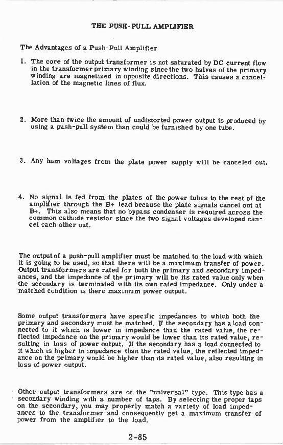
THE PUSH-PULL AMPLIFIER
The Advantages of a Push-Pull Amplifier
1. The core of the output transformer is not saturated by DC current flow in the transformer primary winding since the two halves of the primary winding are magnetized in opposite directions. This causes a cancel-lation of the magnetic lines of flux.
2. More than twice the amount of undistorted power output is produced by using a push-pull system than could be furnished by one tube.
3. Any hum voltages from the plate power supply will be canceled out.
4. No signal is fed from the plates of the power tubes to the rest of the amplifier through the B+ lead because the plate signals cancel out at BA-. This also means that no bypass condenser is required across the common cathode resistor since the two signal voltages developed can-cel each other out.
The output of a push-pull amplifier must be matched to the load with which it is going to be used, so that there will be a maximum transfer of power. Output transformers are rated for both the primary and secondary imped-ances, and the impedance of the primary will be its rated value only when the secondary is terminated with its own rated impedance. Only under a matched condition is there maximum power output.
Some output transformers have specific impedances to which both the primary and secondary must be matched. If the secondary has a load con-nected to it which is lower in impedance than the rated value, the re-flected impedance on the primary would be lower than its rated value, re-sulting in loss of power output. If the secondary has a load connected to it which is higher in impedance than the rated value, the reflected imped-ance on the primary would be higher than its rated value, also resulting in loss of power output.
Other output transformers are of the "universal" type. This type has a secondary winding with a number of taps. By selecting the proper taps on the secondary, you may properly match a variety of load imped-ances to the transformer and consequently get a maximum transfer of power from the amplifier to the load.
2-85

THE PUSH-PULL AMPLIFIER
Review of the Push-Pull Amplifier
PUSH-PULL CIRCUIT uses two vacuum tubes and a transformer to double the power output of the circuit. The tube grid voltages are 180 degrees out of phase.
DISTORTED WAVE FORMS due to overdriving the tubes do not noticeably affect the current wave form in the output trans-former of a push-pull amplifier.
DISTORTED PLATE CURRENT
EFFECTIVE CURRENT IN OUTPUT
TRANSFORMER
PHASE INVERTER produces two signal voltages 180 degrees out of phase without using a trans-former. A phase inverter may use one or two vacuum tubes.
PUSH-PULL POWER AMPLIFIER consists of a voltage amplifier, a phase splitter (inverter), two power amplifier tubes and an output transformer.
II
2-86

MICROPHONES, EARPHONES AND LOUDSPEAKERS
Principles of Sound
When it is desired to send an electric current from one point to another, wires are used to carry tins current. When sound is sent directly from one point to another, it is the particles of air that carry the sound. In other words, in the transmission of electricity or sound, a medium must exist between the points of transmission; with electricity, wires are used, with sound, air is used.
Sound is actually the motion of pressure waves of air. Therefore, any de-vice that produces sound, such as the human vocal cords, is a device for varying the pressure of the surrounding air. All musical instruments make use of this principle by having some part, such as a taut string, a reed or stretched membrane, which when set into vibration, produoes varying pressure waves of air. In the piano, when a key is struck, a taut string is set into vibration. The string vibrates on both sides of its rest-ing point and compresses and expands the surrounding air. When the string (see figure below) moves from its resting point to the right, the air to the right of the string is compressed (increased in pressure). When the string moves to the lei: of its resting point, the air to the right of the string will be expanded (reduced in pressure). If a sound detecting device, such as the human ear, is located in the vicinity of the vibrating string, the varying pressure waves will strike the eardrum and produce the sen-sation of sound.
The number of complete vibrations of the string occurring per second de-termines the frequency or pitch of the resulting sound wave. The intensity or amplitude of the sound wave is determined by the amount of displace-ment of the string from its resting point.
The sound produced by the human voice may vary in intensity in the ratio of 10,000 to 1 and cover a range of about 60 to 10, 000 cycles. In music, the intensity variation may be as great as 100,000 to 1 and the frequency range is from about 40 to 15, 000 cycles.
50(1/ID WA YES
Minimum pressure
pressure
1// /11/1//)2/
Normal pressure (resting position)
of string
PRODUCED BY VIBRATING STRING
Maximum pressure
Normal pressure
Minimum pressure
DIAGRAM OF VARIATION OF PRESSURE TO RIGHT OF STRING
2 -87

MICROPHONES, EARPHONES AND LOUDSPEAKERS
Characteristics of Microphones
The sound waves that you produce when you talk or sing can be converted into corresponding electrical impulses by the mechanism of a microphone. A diaphragm inside the microphone is actuated by the air pressure varia-tions of the sound waves, and in turn causes the microphone to produce an AC voltage of the same frequency as the original sound. The amplitude of this AC voltage will be proportional to the intensity of the sound.
The ratio of electrical output (voltage) to the intensity of sound input is the sensitivity of a microphone. Sensitivity varies widely among different types of microphones. The electrical output of a microphone depends on the type of microphone and the distance between the microphone and the sound source. The output decreases as this distance is increased.
The frequency response of a microphone is a measure of its ability to con-vert different sound frequencies into alternating current. With a fixed sound intensity at the microphone, the electrical output may vary widely as the frequency of the sound source is varied. For clear understanding of speech, however, only a limited frequency range is necessary; from 200 to 4, 000 cycles.
If the output of a microphone shows only small variations in amplitude be-tween its upper and lower frequency limits, it is said to have a flat fre-
quency response.
SOUND LOOKS LIKE THIS
ELECTRICALLY
ef*"96e9 doeoed atave4 igto deaVali
You will study various types of microphones on the next few sheets.
2-88

MICROPHONES, EARPHONES AND LOUDSPEAKERS
The Carbon Microphone
The most common type of microphone, the carbon microphone, is re-stricted to a large extent to communications systems for the transmission of speech. This microphone is the most rugged of all the different types and supplies the largest output from a given sound input.
The figure below shows the principal parts of a single-button carbon micro-phone. This microphone operates by using the varying pressure waves of sound to vary the resistance between carbon granules. These carbon granules are sealed in a brass or carbon cup with an electrode that is mechanically connected to a thin diaphragm. The electrode acts as a plunger in compressing the carbon granules in the cup, which is often called a "carbon button." The carbon button is connected in series with a source of DC voltage and the primary of a microphone transformer.
4ritc,CARBON MICROPHONE
Diaphragm
Carbon or Brass Cip
Carbon Granules
Electrode
a To g Amp. +=''
3
2
Alternating Current
4
Direct Current
Time
When no sound waves strike the diaphragm, the carbon granules are at rest. In this condition, the resistance of the carbon button, between the cup and the electrode, is constant and so is the circuit current. This is illustrated in the region from 1 to 2 in the illustration. When the pressure waves of sound strike the diaphragm, the diaphragm and the attached elec-trode move in and out, varying the pressure on the carbon granules. An increase in air pressure moves the diaphragm in, compressing the carbon granules and lowering their resistance. This causes the current to in-crease, which is shown in the region from 2 to 3 of the graph. A decrease in air pressure causes the diaphragm to move out which reduces the pres-sure on the granules raising their resistance and decreasing the circuit current. This is shown in the region from 3 to 4 of the graph.
In this manner, sound waves vary the circuit current in accordance with the smuid pressure variations. These current variations through the pri-mary of the transformer induce a stepped-up voltage in the secondary which is fed to the grid of an amplifier. The output of the amplifier can be connected to a loudspeaker or used to control the output of a radio transmitter.
2-89

MICROPHONES, EARPHONES AND LOUDSPEAKERS
The Crystal Microphone
One of the disadvantages of the carbon microphone is that it requires an external source of DC voltage for operation. In certain applications, a DC source for the microphone is not easy to obtain. In addition, the car-bon granules may pack together due to the DC current arcing between them. This will eventually reduce the sensitivity of the microphone. Because the granules move around and cause tiny arcs when the microphone is handled, objectionable noise may appear in the output.
The crystal microphone eliminates all the difficulties encountered with the carbon microphone because it operates on a different principle and re-quires no external source of voltage.
Certain crystalline substances such as quartz and Rochelle salts, generate a voltage when pressure is applied. Remember, "How Pressure Produces Electricity" in Basic Electricity? This is known as the piezo-electric ef-fect and this principle is used in crystal microphones.
The construction of a crystal microphone is shown below. The flat crystal of Rochelle salts (used instead of quartz because it is more sensitive) is mounted between two metal plates which have external connections. A thin diaphragm is mechanically connected to the crystal through a hole in the front plate. When the sound waves strike the diaphragm, varying pressure is applied to the crystal through the connecting pin and a varying voltage is produced between the plates. Since the sound waves apply the pressure to the crystal, the output voltage wave form will be an exact duplicate of the original sound.
The crystal microphone is a high impedance microphone and is connected directly to the grid of the amplifier without using a transformer.
nYTA I .........
Metal Plates
Crystal
Diaphragm
Connecting Pin
Shield
External Connections
: . .
2-90
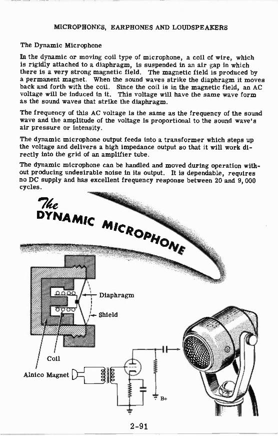
MICROPHONES, EARPHONES AND LOUDSPEAKERS
The Dynamic Microphone
In the dynamic or moving coil type of microphone, a coil of wire, which is rigidly attached to a diaphragm, is suspended in an air gap in which there is a very strong magnetic field. The magnetic field is produced by a permanent magnet. When the sound waves strike the diaphragm it moves back and forth with the coil. Since the coil is in the magnetic field, an AC voltage will be induced in it. This voltage will have the same wave form as the sound waves that strike the diaphragm.
The frequency of this AC voltage is the same as the frequency of the sound wave and the amplitude of the voltage is proportional to the sound wave's air pressure or intensity.
The dynamic microphone output feeds into a transformer which steps up the voltage and delivers a high impedance output so that it will work di-rectly into the grid of an amplifier tube.
The dynamic microphone can be handled and moved during operation with-out producing undesirable noise in its output. It is dependable, requires no DC supply and has excellent frequency response between 20 and 9, 000 cycles.
DYNAMIC M/CROPy
C.rvA
-0-21-- Diaphragm
Shield
Coil
Alnico Magnet D -1 - 1 11
2 -91

MICROPHONES, EARPHONES AND LOUDSPEAKERS
The Ribbon or Velocity Microphone
The ribbon microphone consists of a corrugated ribbon of aluminum alloy, which is suspended in a strong magnetic field so that the ribbon can be moved by the sound waves. As the sound waves move the ribbon back and forth, it cuts the lines of force between the poles of the magnets and a voltage is induced in the ribbon. This voltage is very small but it can be stepped up by a transformer, which is usually enclosed in the microphone casing. In addition to stepping up the voltage, the transformer raises the output impedance of the microphone so that it can be connected through a shielded cable to the grid of an amplifier.
The microphones described previously were pressure operated and had diaphragms which moved because the sound waves raised the air pressure on the front side of the diaphragm above the air pressure on the enclosed back side of the diaphragm. The ribbon microphone has no diaphragm and both front and back sides of the ribbon are exposed to the sound waves. The ribbon moves because of the small spaces between the ribbon and the pole pieces. The air passing through these spaces produces a difference in phase and pressure on the two sides of the ribbon. The voltage induced in the ribbon is determined not by the pressure of the air but by the veloc-ity of the air particles traveling between the ribbon and pole pieces.
Tile addva Alivioplume
Permanent Magnets
Pole Pieces
--------- Flexible Metal Ribbon
- --------Connecting Wire
2-92
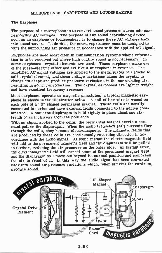
MICROPHONES, EARPHONES AND LOUDSPEAKERS
The Earphone
The purpose of a microphone is to convert sound pressure waves into cor-responding AC voltages. The purpose of any sound reproducing device, such as an earphone or lcudspeaker, is to change these AC voltages back into sound waves. To do this, the sound reproducer must be designed to vary the surrounding air -pressure in accordance with the applied AC signal.
Earphones are used most often in communication systems where informa-tion is to be received but where high quality sound is not necessary. In some earphones, crystal elements are used. These earphones make use of the piezo-electric effect and act like a microphone in reverse. The amplified AC signal voltages are applied to the metal plates of a Rochelle salt crystal element, and these voltage variations cause the crystal to change its shape and produce pressure variations in the surrounding air, resulting in sound reproduction. The crystal earphones are light in weight and have excellent frequency response.
Most earphones operate cn magnetic principles; a typical magnetic ear-phone is shown in the illustration below. A coil of fine wire is wound on each pole of a "U" shaped permanent magnet. These coils are usually connected in series and have external leads connected to the series com-bination. A soft iron diaphragm is held rigidly in place about one six-teenth of an inch away from the pole ends.
With no signal applied to the coils, the permanent magnet exerts a con-stant pull on the diaphragm. When the audio frequency (AC) currents flow through the coils, they become electromagnets. The magnetic fields that are produced by these coils are continuously reversing direction in ac-cordance with the audio signal. At some instant the electromagnetic field will add to the permanent magnet's field and the diaphragm will be pulled in further, reducing the air pressure on the outer side. An instant later, the electromagnetic field will cancel some of the permanent magnet field and the diaphragm will move out beyond its normal position and compress the air in front of it. Li this way the audio signal has been converted back into sound air pressure variations which, when striking the eardrum, produce sound.
Crystal Drive Element
"U" Shaped Magnet
Phone Cord
Diaphragm
Coils
2-93

MICROPHONES, EARPHONES AND LOUDSPEAKERS
The Dynamic Loudspeaker
The dynamic loudspeaker is very similar in construction to the dynamic microphone. In fact, the permanent magnet type of speaker is sometimes used in intercommunication systems as both speaker and microphone.
Cross-sections of the permanent magnet dynamic speaker and the electro-magnet dynamic speaker are shown below. The construction of both types is exactly the same except for the method of obtaining the magnetic field. The electromagnetic type uses a field coil wound on a soft iron coil. A DC current is passed through the field coil and a strong magnetic field is produced in the air gap. In the permanent magnet type, a strong perma-nent magnet made of alnico alloy takes the place of the field coil. A coil of wire, which has relatively few turns, is suspended in the air gap and is attached to a paper cone. The outer edge of the cone and the voice coil suspension are corrugated and attached to the speaker frame. The cor-rugations allow the cone to move in and out freely.
The amplifier is connected to the voice coil through an output transformer which serves as an impedance-matching device. The AC audio signal cur-rent flowing through the voice coil causes it to generate a magnetic field whose polarity is continuously varying. When the voice coil field has a po-larity that aids the field in the air gap, the voice coil and cone move in, reducing the air pressure in front of the cone. When the voice coil field is in opposition to the field in the air gap, the voice coil and cone are pushed out, compressing the air in front of the cone. In this way, audio signal currents are changed into sound pressure waves.
r PERMANENT-MAGNET TYPE
ELECTRO-MAGNET I
Corrugations Speaker Frame
Field Coil
Voice Coil
TYP
Rarified air Compressed air -
1*
Cone moving in Cone pushed out
2-94

MICROPHONES, EARPHONES AND LOUDSPEAKERS
Review of Microphones, Earphones and Loudspeakers
SOUND WAVES are variations in air pressure produced by a vibrating solid body. The speed of vibration deter-mines the pitch of the sound; the am-plitude of vibration determines the loudness of the sound.
MICROPHONES change sound waves into electrical impulses. "Mikes" may be carbon, crystal, dynamic or ribbon type. The electrical impulses are fed into the grid of an amplifier either directly or through a step-up transformer.
EARPHONES operate like micro-phones in reverse, and produce sound waves in response to electrical im-pulses. Both the crystal and magnetic earphones are widely used, the mag-netic type being most common.
LOUDSPEAKERS are used where high quality sound reproduction is required. The dynamic loudspeaker operates like a dynamic microphone in reverse and may be of the permanent or electro-magnet type.
[PERMANENT.MAGNET »% TYPE
Diaphragm
Carbon or Brass Cup
Carbon Granules
Electrode
Metal Plates
Crystal
Diaphragm
Capeectieg Pia
Isla
[Mersa ossectices
To Amp.
2-95

AUDIO AMPLIFIERS
Review of Audio Amplifiers
AMPLIFICATION — The process of v changing a low AC input to a high AC
output. A device which performs ampli-fication is called an amplifier.
THE TRIODE — A vacuum tube similar to a diode but containing a grid which controls plate current between cathode and plate.
TRIODE CHARACTERISTICS — A plot of the variations in plate current as grid voltage changes; a measure of a triode's ability to amplify.
Plate Voltage - 200V
Grid Voltage 14 It N 4 2 II 2
—
4
Grid Voltage -8 -6 -4 :-2 :
GRID BIAS — The amount of grid bias voltage determines the class of ampli-fier operation. In Class A the bias is less than cut off; in Class B bias is at or near cut-off; in Class C bias is much less than cut-off.
TRIODE AMPLIFIER — A simple circuit using a single triode with biasing com-ponents. This circuit is not used alone in actual equipment.
0
2-96
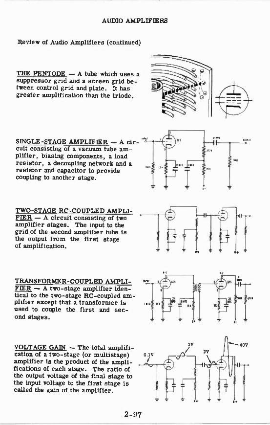
AUDIO AMPLIFIERS
Review of Audio Amplifiers (continued)
THE PENTODE — A tube which uses a suppressor grid and a screen grid be-tween control grid and plate. It has greater amplification than the triode.
SINGLE-STAGE AMPLIFIER — A cir-cuit consisting of a vacuum tube am-plifier, biasing components, a load resistor, a decoupling network and a resistor and capacitor to provide coupling to another stage.
TWO-STAGE RC-COUPLED AMPLI-FIER — A circuit consisting of two amplifier stages. The input to the grid of the second amplifier tube is the output from the first stage of amplification.
TRANSFORMER-COUPLED AMPLI-FIER — A two-stage amplifier iden-tical to the two-stage RC-coupled am-plifier except that a transformer is used to couple the first and sec-ond stages.
VOLTAGE GAIN — The total amplifi-cation of a two-stage (or multistage) amplifier is the product of the ampli-fications of each stage. The ratio of the output voltage of the final stage to the input voltage to the first stage is called the gain of the amplifier.
1-I 1-1
4k11
POI,
P.
4111
2-97

AUDIO AMPLIFIERS
Review of Audio Amplifiers (continued)
AUDIO POWER AMPLIFIER — An am-plifier designed to supply power to a load. Its input is the output of a volt-age amplifier stage. Its output feeds a load through an output transformer.
PHASE INVERTER — A circuit which uses one or two vacuum tubes to pro-duce two signal voltages 180 degrees out of phase. It is also called a phase splitter and replaces the transformer in a push-pull circuit.
PUSH-PULL POWER AMPLIFIER — A circuit consisting of a voltage am-plifier, a phase splitter (inverter), two power amplifier tubes and an out-put transformer.
THE OUTPUT TRANSFORMER — A transformer used to couple the power amplifier output to the load. It matches the low load impedance to the high im-pedance required by the amplifier.
MICROPHONES. EARPHONES AND LOUDSPEAKERS — Carbon, crystal, dynamic and ribbon microphones are used to change sound waves into elec-trical impulses. Earphones and loudspeakers change electrical im-pulses to sound waves.
v-7 In
IIE
e+
2-98

INDEX


INDEX TO VOL. 2
(Note: A cumulative index covering all five volumes in this series will be found at the end of Volume 5.)
Amplification, examples of, 2-1 to 2-3 Amplifiers, 2-1 to 2-10
advantages of push-pull type, 2-85 characteristics of audio power type, 2-71 to 2-73
characteristics of transformer-coupled type, 2-69, 2-70
characteristics of the two-stage type, 2-60, 2-61
classes of, 2-30, 2-31 diagram of push-pull type, 2-84 how they work, 2-17 to 2-19 how the push-pull type works, 2-78 to 2-80
single-stage, 2-55 to 2-57 push-pull type, 2-78 to 2-86 transformer coupled, 2-67 to 2-70 triode type, 2-24 to 2-41 two-stage RC coupled type, 2-58 to 2-66
typical stage, 2-55
Beam power tube, 2-50, 2-51 construction of a typical tube, 2-51
Bias, 8+ power supply, 2-34 battery, 2-32 :athode, 2-35 grid voltage, 2-24 to 2-26 power supply, 2-33
Cathode bypass capacitor, 2-38 to 2-40 Cathode resistor, 2-36, 2-37 Coupling, amplifier stages, 2-59
transformer, 2-67, 2-68
Decoupling filters, 2-56, 2-57
Earphones, 2-93
Frequency response, 2-62 to 2-64 curve, 2-65
Gain, increase of, 2-58
Impedance matching, 2-76, 2-77
Loudspeakers, dynamic type, 2-94
Microphones, 2-88 to 2-92 carbon, 2-89 characteristics of, 2-88
crystal, 2-90 dynamic type, 2-91 ribbon or velocity type, 2-92
Output transformers, 2-74 to 2-77 job of, 2-74, 2-75
Pentodes, 2-47 to 2-49, 2-52, 2-53 construction of a typical tube, 2-49 how they work, 2-48 summary of operation of, 2-52, 2-53
Phase inverters, 2-81 to 2-83 another type of, 2-83 how they work, 2-82
Review, Audio Amplifiers, 2-96 to 2-98 Microphones, Earphones and Loudspeakers, 2-95
The Push-Pull Amplifier, 2-86 The Tetrode and the Pentode, 2-54 The Triode, 2-23 The Triode Amplifier, 2-41 The Two-Stage RC Coupled Amplifier, 2-66
Sound, principles of, 2-87
Tetrodes, 2-42 to 2-46 eliminating effects of secondary emission, 2-47
normal operation of, 2-46 screen grid, 2-43 secondary emission in, 2-44 static characteristics of, 2-45 why they were developed, 2-42
Triodes, 2-11 to 2-23 construction of typical tube, 2-12 control grid in, 2-14, 2-15 how they work, 2-13 similiarity to the diode, 2-16
Triode amplifiers, why proper bias is necessary, 2-27 to 2-29
Triode tube characteristics, amplification factor, 2-20
plate resistance, 2-21 transconductance, 2-22
Vacuum tubes, amplification, 2-11 how they were developed, 2-8, 2-9 types of, 2-6, 2-7 what they can do, 2-4, 2-5
2-101


.

.

- _.
i

Other Famous Training Programs by Van Valkenburgh, Nooger & Neville, Inc.
BASIC ELECTRICITY (5 volumes)
VOLUME 1 — What Electricity Is ... How Electricity Is Produced . How Friction Produces Electricity . . . How Pressure Produces Electricity . . . How Heat Pro-duces Electricity ... How Light Produces Electricity ... How Chemical Action Pro-duces Electricity — Primary Cells . . . How Chemical Action Produces Elec-tricity — Secondary Cells . . . How Mag-netism Produces Electricity . . . Current Flow — What It Is ... Magnetic Fields... How Current Is Measured . . . How A
Meter Works . . . What Causes Current Flow — EMF . . . How Voltage Is Meas-ured . . . What Controls Current Flow — Resistance.
VOLUME 2 — What a Circuit Is . Direct Current Series Circuits . . . Ohm's Law . . . Electric Power . . . Direct Current Parallel Circuits ... Ohm's Law and Par-allel Circuits ... Direct Current Series — Parallel Circuits ... Kirchhoff's Laws.
VOLUME 3 — What Alternating Current Is . . . AC Meters . .. Resistance in AC Cir-cuits . . . Inductance in AC Circuits . . Power in Inductive Circuits . . . Capaci-tance in AC Circuits . . . Capacitors and Capacitive Reactance.
VOLUME 4 — Impedance in AC Series Circuits . . . Current, Voltage and Res-onance in AC Series Circuits . . . Alter-nating Current Parallel Circuits . . . Resonance In AC Parallel Circuits . . . Alternating Current Series — Parallel Cir-cuits . . . Transformers.
VOLUME 5 — Elementary Generators ... Direct Current Generators ... Direct Cur-rent Motors . . . DC Motor Starters . . . DC Machinery Maintenance and Trouble-shooting . . . Alternators ... Alternating Current Motors . . . Power Control De-vices.
BASIC INDUSTRIAL ELECTRICITY (2 vo umes)
VOLUME 1 — Introduction ... Power Dis-tribution . . . Illumination . . . Electro-mecianical Machinery Control . . . Elec-trorrechanical Servo Control Systems... Fluid-Control Devices.
VOLUME 2 — Industrial Fluid-Control Systems . . . Process Control and Prod-uct nspection . . . Remote Monitoring and Control . . . Electric Welding and Heating . . . Miscellaneous Industrial Control Systems.
BASIC SYNCHROS & SERVOMECHANISMS (2 volumes)
VOLUME 1 — Introduction to Synchro Funcarnentals . . . Synchro Generators and Motors ... The Synchro Differential . . . Tie Control Transformer . . . The Synchro Capacitor ... Conclusion to Syn-chro Fundamentals . . . Introduction to Servo Fundamentals . . . Servo Using Bala iced Potentiometers ... Servo Dem-onstra:es Basic Characteristics ... Servo with Synchros . . . A Basic Transducer Positioning Servo.
VOLUME 2 — The Error Detecting Sys-tem . . . The Balanced Potentiometer Error Detector . . . The Control Trans-former Error Detector. ... The Controlling System ... The DC Servo Motor. .. The DC Servo Amplifier. ... The Single Stage DC Servo Amplifier . . . The Two-Stage DC Servo Amplifier . .. DC Servo Ampli-fier Using Diode Vacuum Tubes . . . Gas Tubes in Servo Amplifiers ... The Thyra-tron Gas Tube . . . A Thyratron Motor Contra Circuit . Thyratron Servo Am-plifier Using Amplitude Control... Phase Shift Control for Servo Amplifiers The Ward-Leonard Control System . • . The Amplidyne . . . The AC Servo Motor... An AC Servo Amplifier Using Thyratron Tubes . . . An AC Servo Amplifier Using Vacuum Tubes . . . Oscillations in Servo Systems ... An Electronic Anti-Hunt Cir-cuit . . Two-Speed Synchro Transmis-sion.
JOHN F. RIDER PUBLISHER INC., NE W YORK