by order of the air force instruction 11-2c-5...
TRANSCRIPT

BY ORDER OF THE
SECRETARY OF THE AIR FORCE
AIR FORCE INSTRUCTION 11-2C-5
VOLUME 3 ADDENDA A
1 NOVEMBER 2011
Flying Operations
C-5 OPERATIONS CONFIGURATION AND
MISSION PLANNING
COMPLIANCE WITH THIS PUBLICATION IS MANDATORY
ACCESSIBILITY: Publications and forms are available for downloading or ordering on the e-
Publishing website at www.e-publishing.af.mil
RELEASABILITY: There are no releasability restrictions on this publication.
OPR: AMC/A3VX
Supersedes: AFI11-2C-5V3_ADDENDA-
A, 5 February 2009
Certified by: AF/A3O-A
(Col James W. Crowhurst)
Pages: 23
This supporting instruction implements AFPD 11-2, Aircraft Rules and Procedures. It
establishes policy for the configuration of the C-5 aircraft to safely and successfully accomplish
worldwide mobility missions. This instruction applies to Air Forces Reserve Command (AFRC)
units and Air National Guard (ANG) units. Refer recommended changes and questions about
this publication to the Office of Primary Responsibility (OPR) using the AF Form 847,
Recommendation for Change of Publication; route AF Forms 847 from the field through the
appropriate functional’s chain of command.
This publication requires the collection and or maintenance of information protected by the
Privacy Act of 1974. System of Records Notice F011 AF XO A, Aviation Resource Management
System (ARMS) covers required information. The authority for maintenance of ARMS is Title
37 U.S.C. 301a (Incentive Pay), Public Law 92-204, Section 715 (Appropriations Act for 1973),
Public Laws 93-570 (Appropriations Act for 1974), 93-294 (Aviation Career Incentive Act of
1974), and Privacy Act of 1974 as amended by Executive Order 13478, Amendments to
Executive Order 9397 Relating to Federal Agency Use of Social Security Numbers, November
18, 2008. Ensure that all records created as a result of processes prescribed in this publication
are maintained in accordance with AFMAN 33-363, Management of Records, and disposed of in
accordance with the Air Force Records Disposition Schedule (RDS) located at
https://www.my.af.mil/afrims/afrims/afrims/rims.cfm. The use of the name or mark of any
specific manufacturer, commercial product, commodity, or service in this publication does not
imply endorsement by the Air Force.

2 AFI11-2C-5V3_ADDENDA-A 1 NOVEMBER 2011
SUMMARY OF CHANGES
This revision adds the C-5 M variant to the consolidated equipment and configuration tables,
updates Table 3.1 flare configurations. It also includes several minor equipment nomenclature
and location changes and clarifies fuel efficiency load planning procedures.
Chapter 1—POLICY 4
1.1. General. .................................................................................................................. 4
1.2. Airplane Coding. .................................................................................................... 4
1.3. Responsibility. ....................................................................................................... 4
1.4. Standard Configuration Codes. .............................................................................. 4
1.5. Deviations and Waivers. ........................................................................................ 4
1.6. Weight and Balance. .............................................................................................. 4
1.7. Changes and Supplements. .................................................................................... 4
1.8. References. ............................................................................................................. 4
Table 1.1. Standard Configuration Codes. .............................................................................. 4
Chapter 2—CONSOLIDATED EQUIPMENT TABLES 6
2.1. Scope. ..................................................................................................................... 6
2.2. Forms. .................................................................................................................... 6
2.3. Aircraft Life Sustaining Equipment (ALSE). ........................................................ 6
Table 2.1. Standard Equipment. .............................................................................................. 6
Table 2.2. Required Equipment. ............................................................................................. 8
Chapter 3—CONFIGURATION AND REQUIRED EQUIPMENT WEIGHT AND BALANCE
DATA 12
3.1. Scope. ..................................................................................................................... 12
3.2. General. .................................................................................................................. 12
3.3. Legend of Configurations: ..................................................................................... 12
Table 3.1. {A}{B}{M} CP-1, CP-2, and CP-3 Standard Configuration (All Channel Missions)
Quantities. .............................................................................................................. 12
Table 3.2. {S} C-1, C-2, and C-3 Standard Configuration (All Channel Missions) Quantities. 13
Chapter 4—LOAD PLANNING 15
4.1. Scope. ..................................................................................................................... 15
4.2. General. .................................................................................................................. 15
4.3. Planning for the Loading and Placement of Hazardous Cargo. ............................. 15

AFI11-2C-5V3_ADDENDA-A 1 NOVEMBER 2011 3
4.4. Miscellaneous Data. ............................................................................................... 15
4.5. -{A}{B} Personnel Limitation with One Lavatory Inoperative. ........................... 15
Table 4.1. Standard Weight Information. ............................................................................... 16
Figure 4.1. C-5 Personnel Limitation Chart (when one of the two troop compartment lavatory
compartments is inoperative). ................................................................................ 18
Attachment 1—GLOSSARY OF REFERENCES AND SUPPORTING INFORMATION 19
Attachment 2—INSTRUCTIONS DD FORM 365-4 (WEIGHT AND BALANCE CLEARANCE
FORM F) 21

4 AFI11-2C-5V3_ADDENDA-A 1 NOVEMBER 2011
Chapter 1
POLICY
1.1. General. This instruction establishes basic configurations, standard equipment, and
equipment location aboard the C-5. Included are weight and balance, standard weight and
moment data for use in completing DD Form 365-4, Weight and Balance Clearance Form F-
Transport/Tactical.
1.2. Airplane Coding. This instruction provides coverage for C-5A, C-5B, C-5M, and C-5A
Space Canister Modified (SCM) airplanes. C-5A airplanes are designated by the letter {A} C-5B
by the letter {B}, C-5M by the letter {M}, and C-5A SCM by the letter {S}. Portions of this
instruction are designated by the use of these symbols to indicate applicability to C-5A, C-5B, C-
5M, C-5A SCM, or C-5M SCM airplanes. Items not designated as applicable to either {A}, {B},
{M}, or {S} airplanes are applicable to all four series.
1.3. Responsibility. Air Force units performing services on the C-5 airplane, e.g. terminal
services, support equipment branch, and Aircrew Flight Equipment are responsible for
configuring the aircraft with the equipment listed in this instruction or as outlined in mission
directives. This includes stowage or installation of the equipment according to the configurations
in this instruction and applicable installation directives (i.e. Technical Orders (T.O.) 1C-5A-2-2,
1C-5M-2-2, 1C-5A-21, 1C-5M-21, 1C-5A- 9 and 1C-5M-9). During preflight, aircrew personnel
will ensure that required mission equipment has been provided and properly serviced, installed,
or stowed.
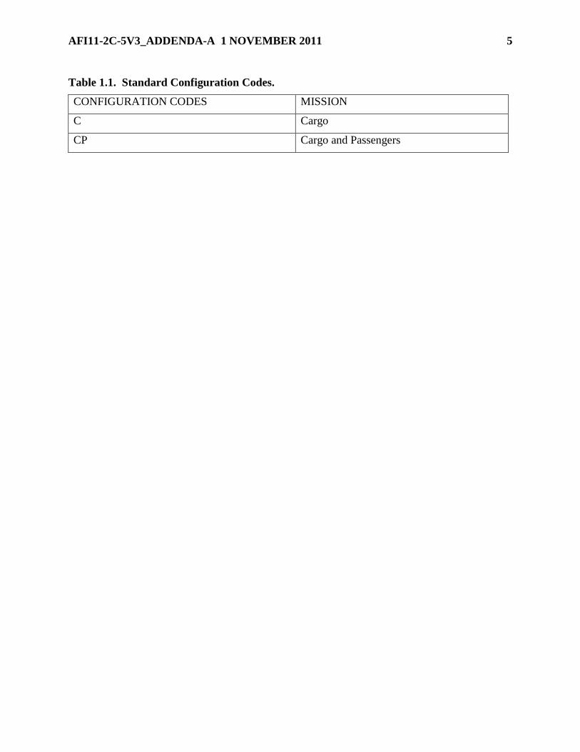
1.4. Standard Configuration Codes. Use the letter codes in Table 1.1 when referring to C-5
configurations. The number that identifies the configuration capability will follow the letter code.
Each configuration code will be indicated in the mission directive.
1.5. Deviations and Waivers. Configurations in this instruction may require deviations for
specific mission requirements. Each mission directive will identify the basic configuration and
any deviations. For example, a Phoenix Banner mission carrying presidential helicopters may
require an additional winch. Deviations may require changes to weight and balance calculations.
1.6. Weight and Balance. To standardize equipment quantities and locations, items shown in
Table 2.1. will be included in the basic weight of the aircraft and remain on the aircraft except
for maintenance and inspection. Equipment in Table 2.2 will be pre-positioned for all local
training and operational missions to meet standard configurations listed in Table 3.1 and will be
entered in reference 5, 6, or 7 of DD Form 365-4. EXCEPTION: To maximize fuel savings
without impacting manpower and storage area requirements, items marked with an asterisk (*) in
tables 2.1 and 2.2 may be removed for local training missions. Any removed equipment must be
placed back onboard the aircraft prior to departing home station for a scheduled mission.
1.7. Changes and Supplements. See AFI 11-2C-5V3, C-5 Operations Procedures, Chapter 1.
1.8. References. See AFI 11-2C-5V3 and the following:
AFI11-2C-5V3_ADDENDA-A 1 NOVEMBER 2011 5
Table 1.1. Standard Configuration Codes.
CONFIGURATION CODES MISSION
C Cargo
CP Cargo and Passengers

6 AFI11-2C-5V3_ADDENDA-A 1 NOVEMBER 2011
Chapter 2
CONSOLIDATED EQUIPMENT TABLES
2.1. Scope. All airplanes will be configured with the equipment listed in Table 2.1. This
equipment will be included in the aircraft basic weight. Items listed in Table 2.2 are added only
as necessary to attain standard configurations listed in Table 3.1 and/or comply with mission
directives.
2.2. Forms. AFVA 11-225, C-5 Passenger Emergency Information Card, informs passengers
of the proper location and use of emergency equipment and exits (see AFI 11-202V3, General
Flight Rules, for passenger briefing card requirements).
2.3. Aircraft Life Sustaining Equipment (ALSE). Configure aircraft in accordance with T.O.
1C-5A-1, Flight Manual, USAF Series, C-5A and C-5B Airplanes, and T.O. 1C-5M-1, Flight
Manual, USAF Series, C-5M Airplanes. Aircraft commanders (AC) may request that additional
equipment be positioned aboard aircraft to accommodate aircrew and passenger increases, as
required. However, units will ensure they do not exceed their total equipment authorizations per
applicable allowance standards (AS).
Table 2.1. Standard Equipment.
Item Equipment Quantity Location/Remarks
1 Aldis lamp/filters 1 Copilot's side console
2 Aviation (AV) fuels identiplate 1 Holder aft of navigator station
3 Cargo winch w/clevis 1 Winch compartment RBL 48
FS 470/2020. Winch computed in aft
compartment.
4 Cargo winch remote control
grip assembly
1 Left side cargo compartment, FS 1215
5 Cord, interphone 1 (25-ft)
2 (50-ft)
1 (175-ft)
As required
6 Crash axe {A}{B}{M} 3 Located according to T.O. 1C-5A-1,
1C-5A-1-2, 1C-5M-1, or 1C-5M-1-2 {S} 2
7 Cryogenic vent nozzles 3 {A}{B}{M} Loose equipment
stowage container left side of cargo
compartment FS 1774 and {S}
airplanes FS 684
8 Detent locking tee (pallet lock) 8 Container left side of cargo
compartment FS 1774 {S} airplanes
FS 684
9 Emergency Escape Breathing
Device (EEBD)/ Protective
Breathing Equipment (PBE)
(see note 8) {A}{B}{M}
8
Located according to T.O. 1C-5A-1,
1C-5A-1-2, 1C-5M-1 or 1C-M-1-2
{S} 6

AFI11-2C-5V3_ADDENDA-A 1 NOVEMBER 2011 7
10 Emergency exit light
{A}{B}{M}
12 Located according to T.O. 1C-5A-1,
1C-5A-1-2, 1C-5M-1 or 1C-M-1-2
{S} 7
11 Escape reel 24 Located according to T.O. 1C-5A-1 or
1C-5M-1
12 Escape rope {A}{B}{M} 8 Located according to T.O. 1C-5A-1,
1C-5A-1-2, 1C-5M-1 or 1C-M-1-2 {S} 3
13 Escape slide {A}{B}{M} 5 Located according to T.O. 1C-5A-1,
1C-5A-1-2, 1C-5M-1 or 1C-M-1-2 {S} 1
14 Fan holder {A}{B}{S} 4 Stowed as loose equipment
in the cargo compartment Fan stop {A}{B}{S} 1
15 Fire extinguisher {A} 15 Located according to T.O. 1C-5A-1,
1C-5A-1-2, 1C-5M-1 or 1C-M-1-2
NOTE: Two additional 1-gallon
HALON 1211 extinguishers are
installed in cargo compartment, one on
each side just fwd of the center wing
area on airplanes not equipped with FE
1301.
{B}{M} 17
{S} 10
16 First aid kit {A}{B}{M} 22 Located according to T.O. 1C-5A-1,
1C-5A-1-2, 1C-5M-1 or 1C-M-1-2 {S} 7
17 Gloves, aramid 1 pr Stowage box in fwd bunk room
18 Ground personnel restraint kit 1 Stowage box in fwd bunk room
19 Kneeling collar 4 Loose equipment stowage container
left side of cargo compartment, FS 684
20 Kneeling pad extend pin 1 Loose equipment stowage container
left side of cargo compartment, FS 684
21 Ladder, rope (stowed) 1 Stowed under floor of courier
compartment FS 962
22 Ladder, utility 1 Stowed as loose equipment in the cargo
compartment
23 Life raft, 25-Person (see notes
7, 8) {A}{B}{M}
4 Located according to T.O. 1C-5A-1,
1C-5A-1-2, 1C-5M-1 or 1C-M-1-2
{S} 1
24 Oil, engine MIL-L-7808 72-quart Stowed as loose equipment in a
suitable container in the cargo
compartment
25 Oil, hydraulic MIL-H-83282 48-quart Stowed as loose equipment in a
suitable container in the cargo
compartment
26 Oven {A}{B}{M} 2 One each located in the relief crew and
troop compartment galleys
{S} 1 Located in the relief crew galley
27 Oxygen bottle {A}{B}{M} 16 Located according to T.O. 1C-5A-1,
1C-5A-1-2, 1C-5M-1 or 1C-M-1-2 {S} 12

8 AFI11-2C-5V3_ADDENDA-A 1 NOVEMBER 2011
Item Equipment Quantity Location/Remarks
28 Pallet stop 4 {A}{B}{M} Loose equipment stowage
container left and right FS 1774 and
{S} airplanes FS 684
29 Pin, landing gear 5 Loose equipment stowage container
left side of cargo compartment FS 684
30 Pressure door upper hinge lock
block assembly w/F-valve
safety guard
2 {A}{B}{M} Loose equipment stowage
container right side of cargo
compartment FS 1774 and {S}
airplanes FS 684
31 Protective covers 33 Located according to T.O. 1C-5A-1 or
1C-5M-1
32 Refrigerator {A}{B}{M}{S} 1 Located in the relief crew galley
{A}{B}{M} 1 Located in the troop compartment
galley
33 Seat, student or instructor 1 Courier compartment baggage area
34 Snatch block assembly 3 Right side of cargo compartment, FS
594 /1734 and left side FS 614
35 Strut limiter 1 Loose equipment stowage container
left side of cargo compartment FS 684
36 Table, relief crew 1 Installed in relief crew compartment
37 Technical publications (See
note 9)
1 set Stowed according to T.O. 1C-5A-5-1,
1C-5A-1, 1C-5M-5-1 or 1C-5M-1
38 Tie-down equipment
MB-1 chains and devices
(10,000-lb capacity)
75 Located according to T.O. 1C-5A-9,
1C-5A-9-1, 1C-5A-5-1, 1C-5A-5-1-1,
1C-5M-9, 1C-5M-9-1, 1C-5M-5-1 or
1C-5M-1-1 MB-2 chains and devices
(25,000-lb capacity)
75
CGU-1/B Straps (5,000-lb
capacity)
50
39 Wheel chocks 4 Stowed as loose equipment in the cargo
compartment
Table 2.2. Required Equipment.
Item Equipment Quantity Location/Remarks
1 Crew comfort items:
Blankets, large 12 Relief crew bunk area
Blankets, small 8 Courier compartment baggage area
Pillows, large w/case 6 Relief crew bunk area
Pillows, small w/case 8 Courier compartment baggage area
Hot cup 1 Crew galley
Coffee pot w/hot plate 1 Crew galley
2 Water container (5-gal) 1 Relief crew baggage area
3 Passenger comfort items
Blankets, small {A}{B}{M} 75 Troop compartment

AFI11-2C-5V3_ADDENDA-A 1 NOVEMBER 2011 9
Pillows, small {A}{B}{M} 75 Troop compartment
Hot cup {A}{B}{M} 1 Troop galley
Coffee pot {A}{B}{M} w/hot
plate
1 Troop galley
1
Water container (5-gal)
{A}{B}{M}
2 Troop galley
Passenger Service Kit
{A}{B}{M}
1 Troop compartment
4 Emergency Passenger Oxygen
System (EPOS) (see notes 2,
8)
{A}{B}{M}{S} 15 Relief Crew and Courier Compartment
{A}{B}{M} 73 Troop compartment
5 Life preservers - crew and
passenger:
Only required on overwater flights.
A-A-50652 life preserver-
adult/child (commercial)
(A/C)(see notes 4, 8)
{A}{B}{M}{S}
20 Flight deck
{A}{B}{M} 80 Troop compartment
LPU-6/P (infant cot) (see note
8) {A}{B}{M}
7 Troop compartment
Life preservers, crew LPU-
10/P (see notes 5, 7, 8)
10 As Required
6 Mask, 358-series w/goggles
(see notes 1, 8)
{A}{B}{M}{S} 11 Flight deck
{A}{B}{M} 6 Cargo compartment
{A}{B}{M} 4 Troop compartment
7 Mask, AWACS (MBU-12P or
-5/P)(see note 8)
{A}{B}{M}{S}
6 Flight deck
8 Mask, Passenger (PAX)
Oxygen (see note 8)
{A}{B}{M}{S} 18 Flight deck
{A}{B}{M} 83 Troop compartment
9 Restraint harness, aircrew, in-
flight (PCU-17/P) w/safety
lanyard (HBU-6/P)(18'6")(see
note 8) {A}{B}{S}
3 Stowage box in fwd bunk room
10 Parachute, BA-22 (see note 3) As
Required
As Required
11 Vest, Survival (see note 6) 10 As Required
12 Aircrew Body Armor (ABA) 10 As Required
12 Kit, Minimum Survival 1 PDM Input Only

10 AFI11-2C-5V3_ADDENDA-A 1 NOVEMBER 2011
(MSK)
13 Emergency Equipment
Demonstration Bag(see note 8)
{A}{B}{M}{S} 1 Courier Compartment
{A}{B}{M} 1 Troop Compartment
14 Protective clothing kit (see
note 8)
2 Relief crew baggage compartment and
troop compartment closet
NOTE: On {S} airplanes kits will be
stowed in relief crew baggage
compartment
15 C-5 Galaxy Passenger
Emergency Information Card
AFVA 11-225 (see note 10)
10 Stowed in seat pouch in courier
compartment
{A}{B}{M} 75 Stowed in seat pouch in troop
compartment
16 Shoring Kit, Plywood:
12" X 12" X 1/2" 8 Stowed as loose equipment in the
cargo compartment 12" X 12" X 3/4" 8
NOTES:
1. Part number (P/N) 358-1506 series oxygen mask with goggles attached is the preferred
smoke and fume protection for aircrew personnel. Firefighters smoke masks may be used until
358-series oxygen masks and goggles are available.
2. EPOS is the preferred system for passenger smoke and fume protection. As a minimum,
each aircraft will have one EPOS per passenger. Preposition additional EPOS for increased
scheduled PAX loads.
3. Add parachutes as required by other configuration publications.
4. The A/C is the preferred LPU for passengers. As a minimum, each aircraft will have one
LPU for each passenger.
5. The LPU-10/P LPU is required to integrate with ALSE and is designed for use by aircrew
personnel. A/C LPUs are not compatible for use with parachutes and survival vests and must
not be used as a substitute for this LPU.
6. Survival Vests are required when parachutes are prepositioned aboard aircraft, or any time
aircrew is flying a combat mission and they are required by theater SPINS. Survival vests
provide crewmembers the necessary survival items while waiting for rescue or return to duty.
Quantities will match number of parachutes aboard aircraft.
7. Aircraft flying over water to Programmed Depot Maintenance (PDM) will load one 25-
person life raft and five LPU-10/Ps to support crewmembers as required.
8. For all aircraft transfers, position ALSE on each aircraft IAW permanent transfer
configuration. Units gaining transferred aircraft, to include PDM aircraft, will contact the
losing organization’s AFE section and initiate transfer of required aircraft-installed ALSE and
inspection records. Gaining AFE organization will conduct an aircraft acceptance inspection
and forward a copy of discrepancies, to include any equipment shortages, to their respective
MAJCOM IAW T.O. 00-20-1. Do not transfer aircraft with less than the required equipment.
The losing organization will make up any necessary shortages from on-hand assets to ensure
transferring aircraft has required equipment installed.

AFI11-2C-5V3_ADDENDA-A 1 NOVEMBER 2011 11
9. Aircraft technical publications may consist of paper or electronic media.
10. AFVA 11-225, C-5 Galaxy Passenger Emergency Information Cards, are required for all
passenger missions.

12 AFI11-2C-5V3_ADDENDA-A 1 NOVEMBER 2011
Chapter 3
CONFIGURATION AND REQUIRED EQUIPMENT WEIGHT AND BALANCE DATA
3.1. Scope. This chapter contains basic cargo compartment configuration and weight, location,
and moment data for associated required equipment.
3.2. General. Deviations to the basic configurations are authorized only to meet specific
mission requirements.
3.3. Legend of Configurations:
3.3.1. {A}{B}{M} CP-1. This configuration offers 36 pallet positions and seats for 73
passengers in the troop compartment. All rollers will be up in this configuration.
3.3.2. {S} C-1. This configuration offers 36 pallet positions. All rollers will be up in this
configuration.
3.3.3. {A}{B}{M} CP-2. This configuration offers a clean cargo compartment floor for
floor-loaded cargo and seats for 73 passengers in the troop compartment. All rollers will be
down in this configuration.
3.3.4. {S} C-2. This configuration offers a clean cargo compartment floor for floor-loaded
cargo. All rollers will be down in this configuration.
3.3.5. {A}{B}{M} CP-3. This configuration offers a mixed combination of palletized cargo
and floor- loaded cargo in the cargo compartment and seats for 73 passengers in the troop
compartment. Rollers will be positioned as the cargo dictates.
3.3.6. {S} C-3. This configuration offers a mixed combination of palletized cargo and floor-
loaded cargo. Rollers will be positioned as the cargo dictates.
Table 3.1. {A}{B}{M} CP-1, CP-2, and CP-3 Standard Configuration (All Channel
Missions) Quantities.
*Asterisk items are not required for local training missions.
EQUIPMENT
STATIONS
FLT
STA
TP
COMP
CGO
COMP
TOTAL
WEIGHT
MOM
Reference 5, DD Form 365-4 (Steward's Equipment)
Blankets, large 620 *12 -- -- 12 42 0.3
Blankets, small in seats *8 *75 -- 83 83 1.3
Pillows, large 620 *6 -- -- 6 12 0.1
Pillows, small in seats *8 *75 -- 83 42 0.7
Hot cup 840/2075 1 *1 -- 2 6 --
Coffee pot w/hot
plate
840/2075 1 *1 -- 2 4 --
Passenger service
kit
2080 -- *1 -- 1 10 0.2
Water container,
5-gal (full)
840/2080 1 *2 -- 3 150 2.4

AFI11-2C-5V3_ADDENDA-A 1 NOVEMBER 2011 13
Expendable
supplies
825/2080 1 *1 -- 2 20 0.3
AFVA 11-225 in seats *10 *75 -- 85 5 --
TOTAL 374 5.3
Reference 6, DD Form 365-4 (Emergency Equipment)
Protective
clothing kit
825/2080 1 1 -- 2 70 1.0
Life vest LPU 6/P 2080 -- *7 -- 7 28 0.6
Life vest A/C 718/1725 20 80 -- 100 151 2.3
EPOS 718/1725 15 73 -- 88 176 2.7
Demonstration
bag
940/2080 1 1 -- 2 10 0.0
TOTAL 435 6.6
Reference 7, DD Form 365-4 (Extra Equipment)
Shoring kit
plywood
443 -- -- 1 1 28 0.1
TOTAL 28 0.1
Additional Extra Equipment (As Required by Mission Directives)
MSCL 501
Flares MJU-10
324 -- -- -- 24 60 0.2
1669/1731 -- -- -- 48 120 2.0
TOTAL 180 2.2
MSCL 502
Flares MJU-7
324 -- -- -- 60 48 0.2
Flares MJU-10 1669/1731 -- -- -- 48 120 2.0
TOTAL 168 2.2
MSCL 503
Flares MJU-53
324 -- -- -- 60 48 0.2
1669/1731 -- -- -- 80 64 1.2
Flares MJU-62 1669/1731 -- -- -- 40 36 0.8
TOTAL 148 2.2
Winch (C-5),
electric
470 -- -- 1 1 300 1.4
Winch (C-5),
hydraulic
470 -- -- 1 1 329 1.5
Table 3.2. {S} C-1, C-2, and C-3 Standard Configuration (All Channel Missions)
Quantities.
*Asterisk items are not required for local training missions.
EQUIPMENT
STATIONS
FLT
STA
TP
COMP
CGO
COMP
TOTAL
WEIGHT
MOM
Reference 5, DD Form 365-4 (Steward's Equipment)
Blankets, large 620 *12 -- -- 12 42 0.3
Blankets, small in seats *8 -- -- 8 8 --
Pillows, large 620 *6 -- -- 6 12 0.1

14 AFI11-2C-5V3_ADDENDA-A 1 NOVEMBER 2011
Pillows, small in seats *8 -- -- 8 4 --
Hot cup 840 1 -- -- 1 3 --
Coffee Pot w/hot
plate
840 1 -- -- 1 2 --
Passenger service
kit
840 *1 -- -- 1 10 --
Water container,
5-gal (full)
840 1 -- -- 1 50 0.4
Expendable
supplies
825 1 -- -- 2 10 0.1
AFVA 11-225 in seats *10 -- -- 10 -- --
TOTAL 141 0.9
Reference 6, DD Form 365-4 (Emergency Equipment)
Protective
clothing kit
825 1 1 -- 2 70 1.0
Life vest A/C 718 20 -- -- 20 30 0.1
EPOS 718 15 -- -- 15 30 0.1
Demonstration
bag
940 1 -- -- 1 5 0.0
TOTAL 135 1.2
Reference 7, DD Form 365-4 (Extra Equipment)
Shoring kit
plywood
443 -- -- 1 1 28 0.1
TOTAL 28 0.1
Additional Extra Equipment (As Required by Mission Directives)
MSCL 501
Flares MJU-10
324 -- -- -- 24 60 0.2
1669/1731 -- -- -- 48 120 2.0
TOTAL 180 2.2
MSCL 502
Flares MJU-7
324 -- -- -- 60 48 0.2
Flares MJU-10 1669/1731 -- -- -- 48 120 2.0
TOTAL 168 2.2
MSCL 503
Flares MJU-53
324 -- -- -- 60 48 0.2
1669/1731 -- -- -- 80 64 1.2
Flares MJU-62 1669/1731 -- -- -- 40 36 0.8
TOTAL 148 2.2
Winch (C-5),
Electric
470 -- -- 1 1 300 1.4
Winch (C-5),
Hydraulic
470 -- -- 1 1 329 1.5

AFI11-2C-5V3_ADDENDA-A 1 NOVEMBER 2011 15
Chapter 4
LOAD PLANNING
4.1. Scope. This chapter contains information to assist personnel in load planning.
4.2. General. Table 4.1 contains standard weight information. The following factors must be
considered during load planning:
4.2.1. The cargo load must be planned so that the center of gravity of the loaded airplane
shall be within specified forward and aft limits. Consideration must also be given to offload
sequence, airplane limitations, and emergency jettisoning. For fuel efficiency, plan for a zero
fuel center of gravity of approximately 38 percent of MAC. NOTE: Any possible addition of
passengers and baggage must be accounted for during planning to prevent the possibility of
exceeding aircraft limitations. For example, if a full load of passengers and baggage could be
added, initially loadplanning for a zero fuel center of gravity of 36 percent of MAC would
prevent exceeding aircraft center of gravity limitations.
4.2.2. Pallets loaded in pallet positions 1, 2, 35, and 36 (forward and aft ramps) shall have a
14-inch access, which shall extend from the outboard edge of the pallet to the vertical
stacking line of the cargo (T.O. 1C-5A-9, and T.O. 1C-5M-9).
4.2.3. No lateral overhang permitted for pallets loaded into the aircraft rail system. Ensure
the maximum width of 104 inches of usable area of the pallet is not exceeded (T.O. 1C-5A-9
and T.O. 1C-5M-9).
4.2.4. The maximum height of cargo for pallet positions 35 and 36 (aft ramp) shall not
exceed 70 inches measured on the aft side of the pallet (T.O. 1C-5A-9, and T.O. 1C-5M-9)
4.2.5. The weight limit on the forward or aft ramp is 7,500 pounds-per-pallet position (T.O.
1C-5A-9, and T.O. 1C-5M-9)
4.2.6. {S} AFT cargo door configuration prohibits left or right straight in loading of
palletized cargo into the logistics rail system (T.O. 1C-5A-9-1, and T.O. 1C-5M-9-1).
4.2.7. When 20 or more passengers or troops are planned, a pallet position shall be left open
to accommodate the palletized baggage.
4.2.8. Do not place cargo in a position that shall restrict the use of the flight deck or troop
compartment ladders.
4.3. Planning for the Loading and Placement of Hazardous Cargo. All classes of hazardous
materials listed as acceptable for air transportation may be transported on the C-5 airplane.
Hazardous cargo that is considered jettisonable shall not be positioned forward of non-
jettisonable cargo, i.e. vehicles, helicopters, pallet trains, etc., except when weight and location
will permit jettisoning by hand. Hazardous jettisonable cargo must be readily accessible and
positioned for emergency jettison.
4.4. Miscellaneous Data.
4.5. {A}{B} Personnel Limitation with One Lavatory Inoperative. The Personnel Limitation
Chart (Figure 4.1.) reflects the number of passengers or troops that one troop compartment

16 AFI11-2C-5V3_ADDENDA-A 1 NOVEMBER 2011
lavatory can accommodate and must be considered when determining the number of personnel
that can be airlifted with one inoperative lavatory.
Table 4.1. Standard Weight Information.
Item Pounds
Aircrew Body Armor (ABA) 8.0
Aircrew restraint harness, in-flight 8.3
Blankets, large 3.5
Blankets, small 1
Buffet/lavatory unit (unserviced) 3,106
Buffet/lavatory unit (serviced) 4,697
Chain, MB-1 7
Chain, MB-2 20
Coffee pot 2
Crew (each) 200
Crew baggage (each) 50
Device, MB-1 3.5
Device, MB-2 6
Duffle bag 100
Emergency Passenger Oxygen System (EPOS) 2
Escape, slide/assembly
{A}{B}{M} No. 3R and 3L exit 71.5 each
{A}{B}{M} No. 4 and 6 exit 71 each
No. 5 exit 70
Flare, MJU 7 0.8
Flare, MJU 10 2.5
Flare, MJU 53 0.8
Flare MJU-62 0.9
Fire extinguisher, portable (1 qt) 9
Fire extinguisher, portable (1 gal) 68
Hot cup 3
Life raft, 25-member, No. 2 exit 151
{A}{B}{M} No. 3R, 4, and 6 exits 136
Life vest LPU 10/P (aircrew) 4
Life vest A/C (adult/child) 1.5
Life vest LPU-6/P (infant cot) 4
Nets, pallet 65
Oil, engine, MIL-L-7808 (one case) 45
Oil, hydraulic, MIL-H-83282 (one case) 42
Oxygen bottle, portable 6
Oxygen mask (all quick-don series) 1
Oven, galley 45
Pallet (HCU-6/E) 290
Parachute, back (aircrew) 28
Passenger service kit 10

AFI11-2C-5V3_ADDENDA-A 1 NOVEMBER 2011 17
Passengers (each) 175
Passenger baggage (each) 70
Pillows, small 0.5
Pillow, large 2
Emergency Escape Breathing Device (EEBD)/Protective
Breathing Equipment (PBE) w/storage case
5
Protective clothing kit 35
Refrigerator, relief crew and troop compartment 227
Ruck sack (training) 40
Ruck sack (combat) 80
Sheets 5
Shoring kit, plywood 28
Shoring
Plywood 1/2" x 4' x 8' 43
3/4" x 4' x 8' 64
Planking 2" x 12" x 12' 72
Straps, CGU 1/B 4
Troops (each) w/web gear and weapon 210
Troops, ground w/ruck sack, web gear, and weapon (combat) 300
Troops, ground w/ruck sack, web gear and weapon (training) 250
Troops, ground w/ruck sack, duffle bag, web gear, and weapon
(combat)
400
Troops, ground w/ruck sack, duffle bag, web gear, and weapon
(training)
350
Vest, Aircrew Body Armor 8
Vest, Survival 10
Water container, 5-gal (full) 50
Wheel chock (20-inch) 14
Winch (heavy duty portable) 792
Winch (C-5), electric 300
Winch (C-5), hydraulic 329

18 AFI11-2C-5V3_ADDENDA-A 1 NOVEMBER 2011
Figure 4.1. C-5 Personnel Limitation Chart (when one of the two troop compartment
lavatory compartments is inoperative).
HERBERT J. CARLISLE, Lt General, USAF
DCS, Operations, Plans & Requirements

AFI11-2C-5V3_ADDENDA-A 1 NOVEMBER 2011 19
Attachment 1
GLOSSARY OF REFERENCES AND SUPPORTING INFORMATION
References
AFI 11-2C-5V3, C-5 Operations Procedures, 7 December 2005
AFI 11-202V3, General Flight Rules, 22 October 2010
AFMAN 33-363, Management of Records, 13 October 2011
AFPD 11-2, Aircraft Rules and Procedures, 14 January 2005
T.O. 00-20-1, Aerospace Equipment Maintenance Inspection, Documentation, Policies, and
Procedures, 1 September 2010
T.O. 1C-5A-1, Flight Manual, 1 July 2007
T.O. 1C-5M-1, Flight Manual, 30 January 2011
T.O. 1C-5A-1-2, Partial Flight Manual, C-5A (SCM) Airplanes, 1 July 2007
T.O. 1C-5M-1-2, Partial Flight Manual, C-5M (SCM) Airplanes, 30 January 2011
T.O. 1C-5A-5-1, Basic Weight Checklist, 15 June 2007
T.O. 1C-5M-5-1, Basic Weight Checklist, 1 October 2010
T.O. 1C-5A-5-1-1, Partial Basic Weight Checklist, C-5A (SCM) Airplanes, 15 June 2007
T.O. 1C-5M-5-1-1, Partial Basic Weight Checklist, C-5M (SCM) Airplanes, 1 October 2010
T.O. 1C-5A-5-2, Loading Data Manual, 15 June 2007
T.O. 1C-5M-5-2, Loading Data Manual, 1 October 2010
T.O. 1C-5A-5-2-1, Partial Loading Data Manual, C-5A (SCM) Airplanes, 15 June 2007
T.O. 1C-5M-5-2-1, Partial Loading Data Manual, C-5M (SCM) Airplanes, 1 October 2010
T.O. 1C-5A-9, Loading Instructions Manual, 15 June 2007
T.O. 1C-5M-9, Loading Instructions Manual, 1 October 2010
T.O. 1C-5A-9-1, Partial Loading Instructions Manual, C-5A (SCM) Airplanes, 15 June 2007
T.O. 1C-5M-9-1, Partial Loading Instructions Manual, C-5M (SCM) Airplanes, 1 October 2010
T.O. 1C-5A-21, Equipment Inventory List, 15 June 2007
T.O. 1C-5M-21, Equipment Inventory List, 1 October 2010
Adopted Forms
AF Form 847, Recommendation for Change of Publication
DD Form 365-3, Chart C, Basic Weight and Balance Record
DD Form 365-4, Weight and Balance Clearance Form-F
AFVA 11-225, C-5 Passenger Emergency Information Card.

20 AFI11-2C-5V3_ADDENDA-A 1 NOVEMBER 2011
Abbreviations and Acronyms
AFE—Aircrew Flight Equipment
AFRC—Air Force Reserve Command
ALSE—Aircrew Life Sustaining Equipment
ANG—Air National Guard
ARMS—Aviation resource Management Systems
CG—Center of Gravity
EEBD—Emergency Escape Breathing Device
EPOS—Emergency Passenger Oxygen System
FS—Fuselage Station
GW—Gross Weight
IAW—In Accordance With
LPU—Life Preserver Unit
MAC—Mean Aerodynamic Chord
MSCL—Mobility Standard Countermeasures Load
PBE—Protective Breathing Equipment
PDM—Programmed Depot Maintenance
SCM—Space Canister Modified
ZFW—Zero Fuel Weight
ZFWCG—Zero Fuel Weight Center of Gravity

AFI11-2C-5V3_ADDENDA-A 1 NOVEMBER 2011 21
Attachment 2
INSTRUCTIONS DD FORM 365-4 (WEIGHT AND BALANCE CLEARANCE FORM F)
A2.1. DD Form 365-4 Heading. Enter date, airplane type, departure station, home station of
airplane, mission number, serial number, destination station (use station nomenclature, not
symbols), and aircraft commander’s rank and last name.
A2.2. Limitations. Enter the appropriate weight and center of gravity (CG) limits for the planned
mission using the following criteria: The maximum gross weight (GW), zero fuel weight (ZFW),
and CG limits specified in the flight manual and loading data manual shall not be exceeded.
A2.2.1. Allowable Takeoff GW. The maximum takeoff GW is 840,000 pounds. Allowable
takeoff GW may be further restricted by critical field length, obstacle clearance, rate of
climb, or weight bearing capacity. Verify the allowable takeoff GW with the flight engineer.
A2.2.2. Allowable Landing GW. The maximum landing weight is 840,000 pounds . When
mission requirements dictate a weight above 635,850 pounds, consult T.O. 1C-5A-1 or T.O.
1C-5M-1, Section V, Sink Rate Limitations, and document the associated allowable sink
speed in the remarks section.
A2.2.3. Allowable ZFW. The maximum ZFW is 665,000 pounds unless nonstandard fuel
sequence procedures are used or aircraft is structurally restricted. Verify the allowable ZFW
with the flight engineer.
A2.3. Reference 1. Enter basic weight and moment from certified copy of DD Form 365-3
(Chart C) in the airplane weight and balance handbook.
A2.4. Reference 2. Leave blank.
A2.5. Reference 3. Enter crew number and location. Use T.O. 1C-5A-5-2 or T.O. 1C-5M-5-2
table 2-1, or enter by compartment centroid. Use fuselage station (FS) 440 for compartment "A";
FS 730 for compartment "B"; FS 917 for compartment "C"; and FS 2031 for compartment "E".
A2.6. Reference 4. Enter crew baggage at 50 pounds each using FS 500. Additional weight
should be added per crewmember when mobility bags are carried.
A2.7. Reference 5, 6 and 7 (see Chapter 3). Enter weight and moment. Also, indicate
configuration used.
A2.8. Reference 8. Enter liquid nitrogen weight and moment. Use FS 1418 for liquid nitrogen
moment computations.
A2.9. Reference 9. The total of references 1 through 8.
A2.10. Reference 10. Enter takeoff fuel (ramp fuel minus 3,000 pounds for taxi and takeoff
roll). Fuel moments may be computed using the interpolation method or using 14 moments for
each 1,000 pounds of fuel over the standard fuel figures in T.O. 1C-5A-5-2 or T.O. 1C-5M-5-2.
A2.11. Reference 11. Leave blank.
A2.12. Reference 12. The total of references 9 and 10.
A2.13. Reference 13. Distribution of Allowable Load:
A2.13.1. Enter 463L pallets with cargo by pallet position or fuselage station.

22 AFI11-2C-5V3_ADDENDA-A 1 NOVEMBER 2011
A2.13.2. Enter vehicles, rolling stock, pallet trains with oversize cargo by CG location.
A2.13.3. Enter passengers or troops in the appropriate compartments, see T.O. 1C-5A-5-2 or
T.O. 1C-5M-5-2, page 2-10, or enter by compartment centroid (Use FS 1675 for
compartment "E".)
A2.14. Reference 14. Enter the ZFW, zero fuel moment, and zero fuel percent of MAC. If the
ZFW CG falls outside the ZFW envelope (loading data manual), the cargo load preplan must be
adjusted.
A2.15. Reference 15. Subtotals; enter totals from reference 13.
A2.16. Reference 16. Enter the total of references 12 and 15.
A2.17. Reference 17. Enter the takeoff CG in percent of MAC.
A2.18. Reference 18. Enter corrections (when applicable).
A2.19. Reference 19. Enter the total of references 16 and 18. If no corrections, leave blank.
A2.20. Reference 20. Enter the corrected CG in percent of MAC. If no corrections, leave blank.
A2.21. Reference 21. Enter ZFW and moment. (Adjust if corrections are made)
A2.22. Reference 22. Leave blank except for airdrop missions.
A2.23. Reference 23. Enter estimated landing fuel weight and moment. Check computerized
flight plan or use 30,000 pounds for first hour of flight and 20,000 pounds per hour for remainder
of flight.
A2.24. Reference 24. Enter the total of references 21 and 23. This weight should not exceed the
allowable landing GW shown in the limitations block.
A2.25. Reference 25. Enter the estimated landing CG in percent of MAC.
A2.26. Remarks Block. Enter nonstandard fuel sequence information, if applicable, the
maneuver load limit (if less than 2.5g), and any aircraft structural weight restrictions.
A2.26.1. Nonstandard fuel sequencing will be used when maintenance problems preclude
the use of certain fuel tanks. Nonstandard fuel procedures are essentially the same as
standard fuel sequencing with the following exceptions:
A2.26.1.1. The flight engineer will inform or provide the loadmaster of the conditions
requiring this configuration and the fuel weight distribution of individual tanks.
A2.26.1.2. Fuel weight moments will be computed using the standard sequence fuel
moment tables in T.O. 1C-5A-5-2, T.O. 1C-5A-5-2-1, T.O. 1C-5M-5-2, and T.O. 1C-
5M-5-2-1.
A2.26.1.3. Special zero fuel weight center of gravity (ZFWCG) restrictions are required
when using nonstandard fuel sequencing. Enter ZFWCG limitation in the limitation
block. (See T.O. 1C-5A-1 or T.O. 1C-5M-1, figure 5-7.).
A2.26.1.4. Weight limitation restriction. Depending on which tanks are empty, the
takeoff and fuel allowable gross weight limitations will be restricted. The landing
limitation will remain at 769,000 pounds. Comply with T.O. 1C-5A-1 or T.O. 1C-5M-1,
section V, Nonstandard Fuel Sequence Procedures.

AFI11-2C-5V3_ADDENDA-A 1 NOVEMBER 2011 23
A2.26.1.5. Use the remarks block to record the fuel breakdown of symmetrical tanks,
weight and moments, i.e., 1 and 4 main tanks 47,000 pounds @ 758 moments. NOTE:
When calculating moments for fuel, use 14 moments for each 1,000 pounds of fuel over
the standard fuel figures contained in T.O. 1C-5A-5-2 or T.O. 1C-5M-5-2.
A2.26.2. Maneuver load limitations apply.
A2.26.2.1. When ZFW does not exceed 590,000 pounds and takeoff GW does not
exceed 769,000 pounds, no entry required.
A2.26.2.2. When ZFW is between 590,000 and 635,000 pounds or takeoff GW is greater
than 769,000 pounds, enter "Maneuver load limit 2.25g.”
A2.26.2.3. When ZFW is between 635,000 and 665,000 pounds, enter "maneuver load
limit 2.0g.”
A2.27. Load Adjuster Number Block. Leave blank.
A2.28. Signature Bloc