by n.golmie… presented by: sushanth...
TRANSCRIPT

By N.Golmie… Presented by:
Sushanth Divvela
1

Agenda Introduction WPAN WLAN Simulation Models Simulation results Concluding remarks
2

Introduc.on Coexistence of WPAN and WLAN Performance evaluation WLAN and Bluetooth when
operating in close proximity. Results are based on MAC, PHY and Wireless channel Results are done using analysis, simulation and
experiment results.
3

Bluetooth Short Range (0-10m) wireless technology Operates in the ISM frequency (2.402 GHz-2.483GHz) 79 RF channels of 1 MHz Antenna power is 1 mW Binary Gaussian Frequency Shift Keying(GFSK) Data rate 1 Mbps TDM is used to divide the channels into 625 micro sec
slots
4

Piconet Master and Slave The Slave always follows the Master packet transmission
Slaves in the piconet synchronize their timing and frequency once the connection is established
5
The two types of link connections : Synchronous Connection‐Oriented (SCO) ‐ Symmetric Point –Point conection between a master
and slave where master sends an SCO packet in one TX slot at regular time intervals,defined by Tsco time slots.
Asynchronous Connection‐Less (ACL) ‐ Asymmetric Point – Point connection between a
master and slave in the piconet which uses ARQ for lost packets.
6

Both ACL and SCO have the same frame format It consists of a 72‐bit access code used for message identification and synchronization, a 54‐bit header and a variable length payload that contains either a voice or a data packet
A repetition code is applied to the header, and a block code is applied to the access code so that up to 13 errors can be detected and 6 can be corrected.
Uncorrected errors in the header and accesscode lead to packet drop.
HV packets do not have CRC in the payloaad.
7

IEEE 802.11b
The IEEE 802.11 standard defines both the physical (PHY) and medium access control (MAC) layer protocols for WLANs
The three different PHY specifications: frequency hopping (FH) spread spectrum, direct sequence (DS) spread spectrum, and IR.
The transmit power for DS and FH devices is defined at a maxi-mum of 1 W and the receiver sensitivity is set to −80 dBmW. Antenna gain is limited to 6 dB maximum.
8

The basic data rate for the DS system is 1 Mbit/s encoded with differential binary phase shift keying (DBPSK).
Higher rates of 5.5 and 11 Mbit/s are also available using techniques combining quadrature phase shift keying and complementary code keying (CCK)
All the systems use 22 MHz channels
9
MAC layer Coordinate the communication between stations and
control the behavior of users who want to access the network.
The Distributed Coordination Function (DCF), which describes the default MAC protocol operation, is based on a scheme known as carrier-sense, multiple access, collision avoidance (CSMA/CA).
Both the MAC and PHY layers co- operate in order to implement collision avoidance procedures
10

Carrier sense is used to determine if the channel is busy. A virtual carrier sense mechanism is also provided at the
MAC layer. It uses the request-to-send (RTS) and clear-to- send (CTS) message exchange to make predictions of future traffic
11

Simula(on model The PHY, and MAC layers developed in C and OPNET For interference to occur, the packets must overlap in both
time and frequency. The bit errors in the packet depends on :
(1) the signal-to-interference ratio (SIR) and the signal-to-noise ratio at the receiver
(2) the type of modulation used by the transmitter and the interferer
(3) the channel model
12
MAC model: Bluetooth hopping pattern algorithm is implemented using OPNET.
The MAC/PHY interface module is used for 802.11b in the OPNET library.
PHY model: The receiver at the Bluetooth is noncoherent limiter‐discriminator receiver.
The 802.11b uses CCK reciever. Channel model:
Line of Sight propagation for first 8m and a propagation exponent of 3.3 for distances over 8m.
AWGN is used to model noise at recievers
13

Simula.on Results Factors effecting interference
‐ WLAN transmission power ‐ Offered load ‐ Bluetooth traffic type ‐ Bluetooth transmission power
Realistic interference topologies ‐ WLAN device in the midst of Bluetooth Piconets ‐ WLAN access point acting as a source
14
Scenaio 1: The WLAN mobile is the generator of data and WLAN AP is the sink.
Scenario 2: The traffic is generated at the AP and received at the WLAN mobile.
For Bluetooth voice and data applications are considered
Voice – 64kbps using HV1 packet encapsulation The packet interarrival time is Tb is exponentially distributed.
For WLAN 11 Mbps is used . The packet payload is fixed to 12000 bits and vary the offered load.
15
WLAN transmitted power: Saturation around 10 mW Between 1 mW and 5 mW a small change in WLAN power triples the Bluetooth packet loss.
As offered load increases the packet loss increases Voice has the lowest packet loss The packet loss decreases as the WLAN transmitted power increases .
Between 1 and 5 mW there is a bump due to closed‐loop interfernce.
16

Probability of packet loss for Bluetooth slave
17
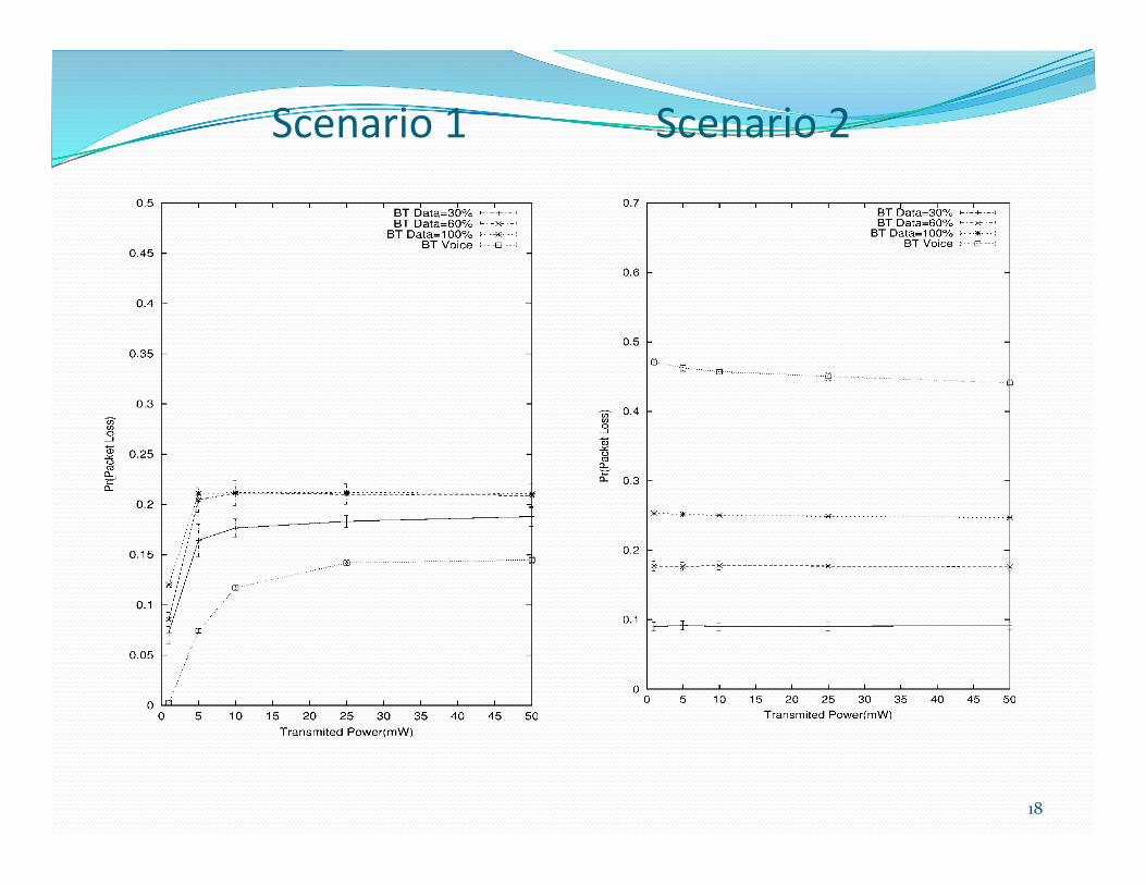
Scenario 1 Scenario 2
18

Probability of packet loss for WLAN mobile device The packet loss decreases as the WLAN transmited power increases.
Between 1 and 5 mW there is a bump this is due to closed loop interference.
Probability of packet loss for WLAN source The packet loss for WLAN does not change. Increase in power does not necessarily improve the performance.
19
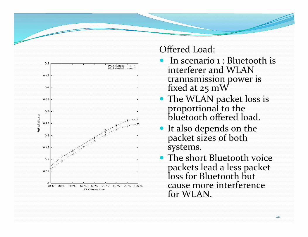
Offered Load: In scenario 1 : Bluetooth is interferer and WLAN trannsmission power is fixed at 25 mW
The WLAN packet loss is proportional to the bluetooth offered load.
It also depends on the packet sizes of both systems.
The short Bluetooth voice packets lead a less packet loss for Bluetooth but cause more interference for WLAN.
20

Realis.c interference topologies Topology 1:
When WLAN system is not operating the Bluetooth packet loss is negligible
As the Bluetooth offered load is increased . WLAN packet loss increased.
Bluetooth Voice is worst case interference for the WLAN.
21
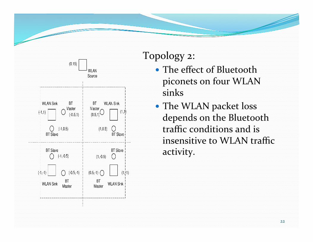
Topology 2: The effect of Bluetooth piconets on four WLAN sinks
The WLAN packet loss depends on the Bluetooth traffic conditions and is insensitive to WLAN traffic activity.
22

Concluding remarks Performance of Bluetooth and WLAN and analyzed. The power control may have limited benefits. Limiting the WLAN power may help avoid interference
with Bluetooth devices. Bluetooth voice represents the worst type of interference
for WLAN. WLAN performance seems to degrade as the Bluetooth
offered load is increased ECC on Bluetooth is of little use
23
Achieving acceptable performance for a particular system comes at the expense of the other system’s throughput.
24

Thank You Questions ..
25