by jim phillips, p. e. -...
TRANSCRIPT
● by Jim Phillips, P. E.
Hazardous locations.qxd 9/22/05 8:48 PM Page 64
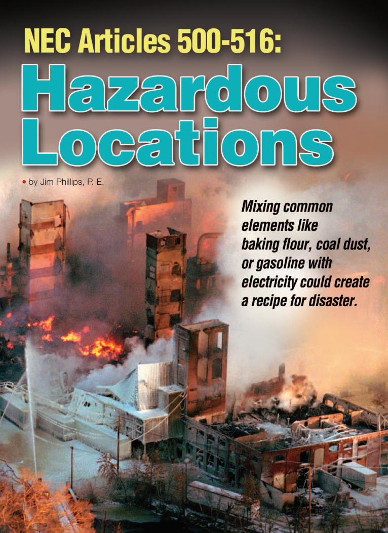
Baking flour, coal dust and gasoline;what do these things have in common?They are not the ingredients for astrange new cake recipe. Each of these“ingredients” is the fuel that could causea major explosion or fire. Grain silos,coal unloading facilities, refineries allhave characteristics that if a sparkoccurs at the wrong place at the wrongtime, it could be a recipe for disaster.These sites have areas that could beconsidered hazardous due to the presence of explosive material in theatmosphere. Something as simple as asmall spark from opening a switch orthe heat produced from a light fixturecould be all it takes to ignite the fueland create an explosion or fire. In fact,many electrical components have thecapability to ignite an explosive or combustible atmosphere due to:• Arcing of electrical components• High temperatures produced by
the equipment • Electrical equipment failure from
events such as short circuits.
The NEC and Hazardous LocationsThe NEC defines a “Hazardous Location” as a location“where fire or explosion hazards may exist due to flam-mable gases or vapors, flammable liquids, combustibledust, or ignitable fibers or flyings.” There are 13 articlesand 68 pages in the NEC regarding hazardous locations,installation practices and equipment requirements.Understanding what makes a location “hazardous” is thefirst step in providing a safer electrical system.
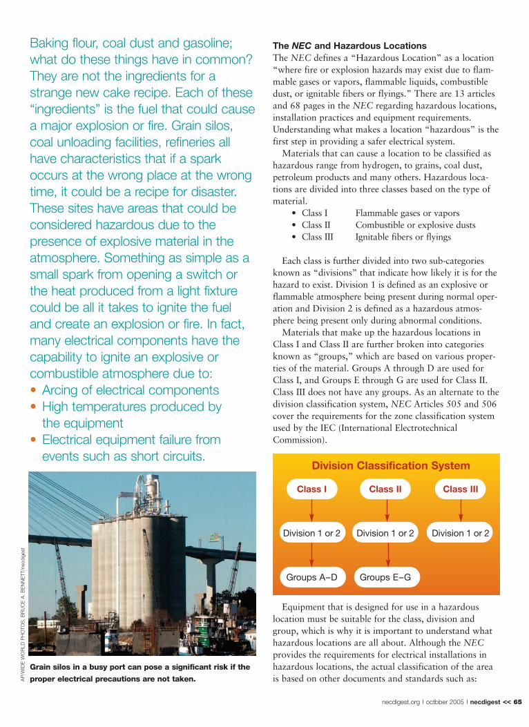
Materials that can cause a location to be classified ashazardous range from hydrogen, to grains, coal dust,petroleum products and many others. Hazardous loca-tions are divided into three classes based on the type ofmaterial.
• Class I Flammable gases or vapors • Class II Combustible or explosive dusts• Class III Ignitable fibers or flyings
Each class is further divided into two sub-categoriesknown as “divisions” that indicate how likely it is for thehazard to exist. Division 1 is defined as an explosive orflammable atmosphere being present during normal oper-ation and Division 2 is defined as a hazardous atmos-phere being present only during abnormal conditions.
Materials that make up the hazardous locations inClass I and Class II are further broken into categoriesknown as “groups,” which are based on various proper-ties of the material. Groups A through D are used forClass I, and Groups E through G are used for Class II.Class III does not have any groups. As an alternate to thedivision classification system, NEC Articles 505 and 506cover the requirements for the zone classification systemused by the IEC (International ElectrotechnicalCommission).
Equipment that is designed for use in a hazardouslocation must be suitable for the class, division andgroup, which is why it is important to understand whathazardous locations are all about. Although the NECprovides the requirements for electrical installations inhazardous locations, the actual classification of the areais based on other documents and standards such as: A
P/W
IDE
WO
RLD
PH
OTO
S, B
RU
CE
A. B
EN
NE
TT/n
ecdi
gest
Division Classification System
Class I Class II Class III
Division 1 or 2 Division 1 or 2 Division 1 or 2
Groups A–D Groups E–G
Grain silos in a busy port can pose a significant risk if the
proper electrical precautions are not taken.
necdigest.org octbber 2005 necdigest << 65
Hazardous locations.qxd 9/22/05 8:49 PM Page 65
• ANSI/NFPA 30 Flammable and Combustible Liquids Code
• NFPA 54 National Fuel Gas Code• NFPA 58 Liquefied Petroleum Gas Code• NFPA 59 Utility LP-Gas Plant Code• ANSI/NFPA 497 Recommended Practice for the
Classification of Flammable Liquids, Gases or Vapors and of Hazardous Locations for Electrical Installations in Chemical Process Areas.
• ANSI/NFPA 499 Recommended Practice for the Classification of Combustible Dusts and of Hazardous Locations for Electrical Installations in Chemical Process Areas.
CLASS I LOCATIONS – Explosive Vapors and GasesFacilities such as gasoline dispensing stations, refineries,chemical plants and many other facilities with flammablegases and vapors, are Class I locations. The vapors andgases in Class I are further categorized into one of fourgroups depending on various physical characteristics ofthe material and how volatile and dangerous it might be.Explosion-proof apparatus is one type of equipment usedin a Class I location. This equipment must also be suit-able for the material group.
Explosion-Proof ApparatusThe NEC defines Explosion-Proof Apparatus as:“Apparatus enclosed in a case that is capable of with-standing an explosion of a specified gas or vapor that mayoccur within it and of preventing the ignition of a speci-fied gas or vapor surrounding the enclosure by sparks,flashes, or explosion of the gas or vapor within, and thenoperates at such an external temperature that a surround-ing flammable atmosphere will not be ignited thereby.”
“Explosion-Proof” equipment is not literally explosionproof. Contrary to popular belief, an explosion couldoccur inside the enclosure, but it must be capable of with-standing and safely releasing the pressure without ignitingthe surrounding atmosphere.
If the cover to the equipment is removed, the haz-ardous gas/vapor could enter the box and becometrapped inside when the cover is reinstalled. Vapor mayalso enter through process connections and through grad-ual seepage. A spark that occurs inside the box couldignite the trapped gas/vapor producing an explosion. Thebox must not rupture and must safely release the pressurebuildup from the rapid expansion of the hot gas andflame without igniting the surrounding atmosphere.
An explosion-proof design may use one of severalmethods to ensure that any explosion that occurs insidethe explosion-proof enclosure does not propagate outsideof it. Explosion pressures must be released, so the enclo-sure is designed to cool the gases so that they will not
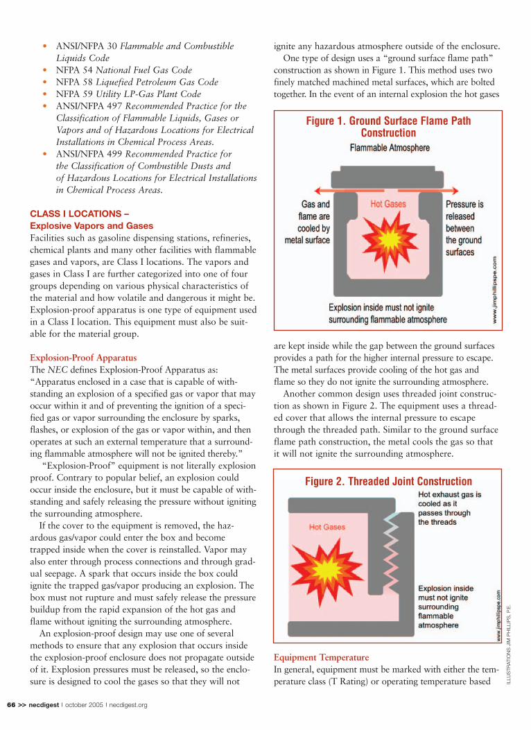
ignite any hazardous atmosphere outside of the enclosure. One type of design uses a “ground surface flame path”
construction as shown in Figure 1. This method uses twofinely matched machined metal surfaces, which are boltedtogether. In the event of an internal explosion the hot gases
are kept inside while the gap between the ground surfacesprovides a path for the higher internal pressure to escape.The metal surfaces provide cooling of the hot gas andflame so they do not ignite the surrounding atmosphere.
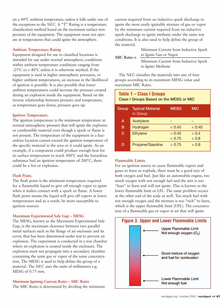
Another common design uses threaded joint construc-tion as shown in Figure 2. The equipment uses a thread-ed cover that allows the internal pressure to escapethrough the threaded path. Similar to the ground surfaceflame path construction, the metal cools the gas so thatit will not ignite the surrounding atmosphere.
Equipment TemperatureIn general, equipment must be marked with either the tem-perature class (T Rating) or operating temperature based
Figure 2. Threaded Joint Construction
66 >> necdigest october 2005 necdigest.org
Figure 1. Ground Surface Flame PathConstruction
ILLU
STR
ATIO
NS
JIM
PH
ILLI
PS
, P.E
.
Hazardous locations.qxd 9/22/05 8:51 PM Page 66
on a 40ºC ambient temperature, unless it falls under one ofthe exceptions to the NEC. A “T” Rating is a temperatureclassification method based on the maximum surface tem-perature of the equipment. The equipment must not oper-ate at temperatures that could ignite the atmosphere.
Ambient Temperature RatingEquipment designed for use in classified locations isintended for use under normal atmospheric conditionswithin ambient temperature conditions ranging from -25ºC to + 40ºC unless it is otherwise marked. If theequipment is used in higher atmospheric pressures, orhigher ambient temperatures, an increase in the likelihoodof ignition is possible. It is also possible that lower ambient temperatures could increase the pressure createdduring an explosion inside the equipment. Based on theinverse relationship between pressure and temperature, as temperature goes down, pressure goes up.
Ignition Temperature.The ignition temperature is the minimum temperature atnormal atmospheric pressure that will ignite the explosiveor combustible material even though a spark or flame isnot present. The temperature of the equipment in a haz-ardous location cannot exceed the ignition temperature ofthe specific material in the area or it could ignite. As anexample, if a component could produce enough heat forits surface temperature to reach 300ºC and the hazardoussubstance had an ignition temperature of 280ºC, therecould be a fire or explosion.
Flash Point. The flash point is the minimum temperature required for a flammable liquid to give off enough vapor to ignitewhen it makes contact with a spark or flame. A lowerflash point means the liquid will give off vapors at lowertemperatures and as a result, be more susceptible to ignition sources
Maximum Experimental Safe Gap – MESGThe MESG, known as the Maximum Experimental SafeGap, is the maximum clearance between two parallelmetal surfaces such as the flange of an enclosure and itscover, that has been determined under test to prevent anexplosion. The experiment is conducted in a test chamberwhere an explosion is created inside the enclosure. Theexplosion must not propagate into a secondary chambercontaining the same gas or vapor of the same concentra-tion. The MESG is used to help define the group of amaterial. The NEC uses the units of millimeters e.g.MESG of 0.75 mm.
Minimum Igniting Current Ratio – MIC RatioThe MIC Ratio is determined by dividing the minimum
current required from an inductive spark discharge toignite the most easily ignitable mixture of gas or vaporby the minimum current required from an inductivespark discharge to ignite methane under the same testconditions. It is also used to help define the group of the material.
Minimum Current from Inductive Spark to Ignite Gas or Vapor
MIC Ratio =Minimum Current from Inductive Spark to Ignite Methane
The NEC classifies the materials into one of fourgroups according to its maximum MESG value and maximum MIC Ratio.
Flammable LimitsFor an ignition source to cause flammable vapors andgases to burn or explode, there must be a good mix ofboth oxygen and fuel. Just like an automobile engine, toomuch oxygen with not enough fuel and the mix is too“lean” to burn and will not ignite. This is known as thelower flammable limit or LFL. The same problem occursat the other end of the scale as well. Too much fuel withnot enough oxygen and the mixture is too “rich” to burn,which is the upper flammable limit (UFL). The concentra-tion of a flammable gas or vapor in air that will ignite
Figure 3. Upper and Lower Flammable Limits
necdigest.org october 2005 necdigest << 67
Table 1 – Class I GroupsClass I Groups Based on the MESG or MIC
Group Typical Material MESG MICIn Group
A Acetylene - -
B Hydrogen < 0.45 < 0.40
C Ethylene > 0.45 > 0.4< 0.75 < 0.8
D Propane/Gasoline > 0.75 > 0.8
Hazardous locations.qxd 9/22/05 8:52 PM Page 67

GE
TTY
IMA
GE
S
and continue to burn falls somewhere between the upperand lower flammable limits.
Vapor DensityHazardous location design also depends on how heavythe gas or vapor is. Vapor density is an indicator ofwhether a gas will tend to rise towards the ceiling or set-tle towards the floor in normal atmospheric pressure andtemperature. The density is based on the weight of a vol-ume of the vapor or gas with no air compared to theweight of the same volume of air. A ratio of less thanone indicates the vapor is lighter than air and will risetowards the ceiling where hot lighting fixtures are locat-ed. A ratio greater than one indicates the vapor is heav-ier than air and will settle towards the ground.
CLASS II LOCATIONS – Combustible DustDusts can be suspended in air for a period of time,forming a dust cloud. Similar to Class I locations, whenthere is a sufficient concentration of dust in the air,there can be a violent explosion when ignited.Combustible dusts have many characteristics thatdefine their ignition properties. These properties indi-cate how easily the dust ignites and how severe theexplosion would be. Dusts with similar ignition proper-ties are classified into one of three groups that the NEC
defines as:
Group E Metal dustGroup F Coal and similar dustGroup G Grain dust
A measurement used to determine how easily a com-bustible dust can ignite is defined as the ignition sensitivi-ty. Dust ignition is a function of the concentration of thedust, the ignition temperature and the minimum energythat it takes for ignition to occur.
Explosion severity is the measure of how violent theexplosion will be. This is based on the maximum explo-sion pressure, maximum rate of pressure rise, and howlong the pressure will last. All of these help determine thedestructive capability of the explosion.
Ignition TemperatureIn the absence of a spark or flame, a combustible dustcould also be ignited due to an electrical component’stemperature exceeding the ignition temperature of thedust. The ignition temperature of a dust layer is usuallylower than a dust cloud. Dust clouds are unlikely toignite from high temperatures alone. Most dust cloudsneed a large amount of energy to ignite, so it usuallytakes a spark or flame to cause the explosion.
The size of the dust particles as well as their moisturecontent can have an effect on the explosiveness. Smallerparticles are easier to ignite – as the particle size getssmaller, the pressure rise will be greater and the ignitiontemperature, explosive limit concentration, and energyrequired for ignition, will be lower. Dust that has ahigher moisture content will have a higher ignition tem-perature rating and it also affects electrical conductivity.However most ignition sources have more than enoughheat to evaporate the moisture.
Dust-Ignition-Proof EquipmentDust-ignition-proof equipment is used in Class II areas.The equipment is designed to keep dust out of the enclo-sure. Since sparks or arcing may occur inside the enclo-sure due to component operation or failure, the designmust prevent the escape of flames or sparks that couldignite dust in the surrounding atmosphere. Class II enclo-sures are different than Class I because they do not haveto contain an explosion. This is because it is unlikely thatthere would be enough dust suspended inside the enclo-sure to cause an explosion inside the box. It is very
68 >> necdigest october 2005 necdigest.org
In the absense of a spark or flame, a combustible dust could also be ignited
due to an electrical component's temperatureexceeding the ignition temperature of the dust.
Hazardous locations.qxd 9/22/05 8:54 PM Page 68

important that the exterior surface of the enclosureremains cool enough to not ignite dust that might accu-mulate on it or be suspended in the surrounding atmos-phere. The equipment’s design must also consider theincrease in heat that results from the insulating effect ofthe dust buildup on the equipment’s surface.
Small Dust Cloud – Big ExplosionHow can an entire facility be destroyed by the ignition ofa dust cloud unless the cloud filled the entire place? Manymajor explosions have occurred that began with the igni-tion of a small localized dust cloud. Research and investi-gations have shown that even an explosion of a smalllocalized dust cloud can be devastating because often twoexplosions actually occur. The first is the explosion creat-ed by ignition of the local dust cloud. This initial explo-
sion shakes loose the years of dust that has settledthrough other parts of the building, which then ignites,resulting in a much bigger secondary explosion.
Class III Locations – Ignitable Fibers and FlyingsClass III locations may contain easily ignitable fibers orflyings such as found in textile mills or sawmills. In these
types of facilities, the fibers or flyings are not likely to besuspended in the atmosphere, forming a cloud that couldignite or explode like Class II locations. However, ifenough material accumulates on the surface of equipmentsuch as lamps, motors or other similar heat producingcomponents and the surface becomes hot enough to ignitethe fibers or flyings, a fast burning fire could result.
Similar to equipment used for Class II locations, equip-ment designed for Class III locations must minimize theability of fibers and flyings to enter the equipment. Thedesign must also prevent sparks, hot metal particles orburning material that could occur during an equipmentfailure from leaving the box. To prevent the ignition ofthe fibers that accumulate on the box, the equipmentmust operate at temperatures below the material’s igni-tion temperature.
Dust-Tight ApparatusDust-tight apparatus is frequently used in Class III loca-tions. This type of apparatus is sealed so that dust, fibersand flyings do not enter the enclosure under specific testconditions.
Reducing the RiskSince it takes fuel, oxygen and an ignition source to cre-ate a fire or explosion, eliminating any one of the threecomponents is critical to providing a safer electrical sys-tem. Keeping sparks and heat away from the fuel is themain objective of most electrical equipment installationsin classified locations. Whether this is done with explo-sion-proof apparatus, dust-ignition-proof or dust-tightenclosures, the goal is the same. Keep the ignition sourceaway from the fuel and oxygen.
The NEC also addresses other protection methods that might be used in hazardous locations. These methods include the use of purged or pressurized systemsthat keep the fuel away from the ignition source, intrinsically safe systems (per ANSI/UL 913), as well as a few other methods. In addition the NEC addressessuitable conduit, wiring and conduit seals to create acomplete system
In all, the NEC provides 13 Articles covering 68 pagesso that the design and installation of electrical systems inhazardous locations will be safer. One final designmethod that is frequently used is actually the safestmethod of all. Locate electrical equipment outside of thehazardous area whenever possible. Don’t let the wrongmix of ingredients be your recipe for disaster! �
In all, the NEC provides 13 Articles covering 68 pages so that
thedesignand installationofelectricalsystemsin hazardous locations will be safer.
GE
TTY
IMA
GE
S
The presence of coal dust, which is highly combustible,
poses less risk of ignition and explosion outdoors than it
does indoors where it constitutes an NEC Class II
Hazardous Location.
necdigest.org october 2005 necdigest << 69
Hazardous locations.qxd 9/22/05 8:56 PM Page 69