bwr14 technology manual (r-104b) - nrc.gov · 0201 course objectives (r-104b) the bwr/4 technology...
TRANSCRIPT
IRWR/4 Technninpv Manual Course IA1anual PrefaceT�WRi'4 Tpe'hnnlnpi Manual Course Manual Preface
UNITED STATESNUCLEAR REGULATORYCOMMISSION
TECHNICAL TRAINING CENTER
- 0
I-
BWR14 TECHNOLOGY MANUAL (R-104B)
This manual is a text and reference document for the BWR/4 Technology Course. It should be used bystudents as a study guide during attendence at this course. This manual was compiled by staffmembers of the Technical Training Division in the Office for Analysis and Evaluation of OperationalData.
The information in this manual was developed or compiled for NRC personnel in support of internaltraining and qualification programs. No assumptions should be made as to its applicability for anyother purpose. Information or statements contained in this manual should not be interpreted as settingofficial NRC policy. The data provided are not necessarily specific to any particular nuclear powerplant, but can be considered to be representative of the vendor design.
4123
______ Technica Tr_ Center _. A-USNRC Technical Training Center Keyc VJ1X0
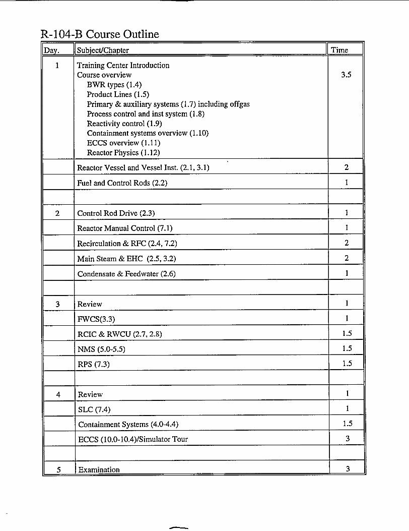
R-104-B Course Outline|Day. IiSubject/Chapter || Time ]
1 Training Center IntroductionCourse overview 3.5
BWR types (1.4)Product Lines (1.5)Primary & auxiliary systems (1.7) including offgasProcess control and inst system (1.8)Reactivity control (1.9)Containment systems overview (1.10)ECCS overview (1.11)Reactor Physics (1.12)
Reactor Vessel and Vessel Inst. (2.1, 3.1) 2
Fuel and Control Rods (2.2) 1
2 Control Rod Drive (2.3) 1
Reactor Manual Control (7.1) 1
Recirculation & RFC (2.4, 7.2) 2
Main Steam & EHC (2.5, 3.2) 2
Condensate & Feedwater (2.6) 1
3 Review 1
FWCS(3.3) 1
RCIC & RWCU (2.7, 2.8) 1.5
NMS (5.0-5.5) 1.5
RPS (7.3) 1.5
4 Review I
SLC (7.4) 1
Containment Systems (4.0-4.4) 1.5
ECCS (10.0-10.4)/Simulator Tour 3
5 Examination 3
0201
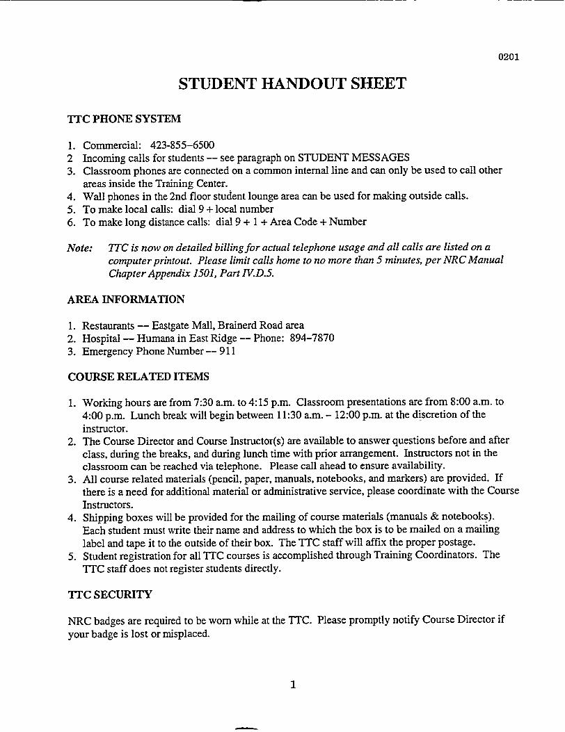
STUDENT HANDOUT SHEET
TTC PHONE SYSTEM
1. Commercial: 423-855-65002 Incoming calls for students -- see paragraph on STUDENT MESSAGES3. Classroom phones are connected on a common internal line and can only be used to call other
areas inside the Training Center.4. Wall phones in the 2nd floor student lounge area can be used for making outside calls.5. To make local calls: dial 9 + local number6. To make long distance calls: dial 9 + 1 + Area Code + Number
Note: 7TC is now on detailed billing for actual telephone usage and all calls are listed on acomputer printout. Please limit calls home to no more than 5 minutes, per NRC ManualChapter Appendix 1501, Part IV.D.5.
AREA INFORMATION
1. Restaurants -- Eastgate Mall, Brainerd Road area2. Hospital -- Humana in East Ridge -- Phone: 894-78703. Emergency Phone Number -- 911
COURSE RELATED ITEMS
1. Working hours are from 7:30 a.m. to 4:15 p.m. Classroom presentations are from 8:00 a.m. to4:00 p.m. Lunch break will begin between 11:30 am. - 12:00 p.m. at the discretion of theinstructor.
2. The Course Director and Course Instructor(s) are available to answer questions before and afterclass, during the breaks, and during lunch time with prior arrangement. Instructors not in theclassroom can be reached via telephone. Please call ahead to ensure availability.
3. All course related materials (pencil, paper, manuals, notebooks, and markers) are provided. Ifthere is a need for additional material or administrative service, please coordinate with the CourseInstructors.
4. Shipping boxes will be provided for the mailing of course materials (manuals & notebooks).Each student must write their name and address to which the box is to be mailed on a mailinglabel and tape it to the outside of their box. The TTC staff will affix the proper postage.
5. Student registration for all TTC courses is accomplished through Training Coordinators. TheTTC staff does not register students directly.
YTC SECURITY
NRC badges are required to be worn while at the TTC. Please promptly notify Course Director ifyour badge is lost or misplaced.
1
0201
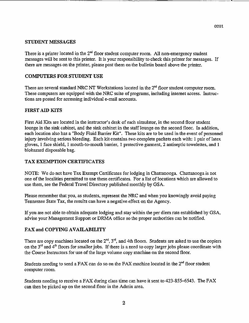
STUDENT MESSAGES
There is a printer located in the 2nd floor student computer room. All non-emergency studentmessages will be sent to this printer. It is your responsibility to check this printer for messages. Ifthere are messages on the printer, please post them on the bulletin board above the printer.
COMPUTERS FOR STUDENT USE
There are several standard NRC NT Workstations located in the 2nd floor student computer room.These computers are equipped with the NRC suite of programs, including internet access. Instruc-tions are posted for accessing individual e-mail accounts.
FIRST AID KITS
First Aid Kits are located in the instructor's desk of each simulator, in the second floor studentlounge in the sink cabinet, and the sink cabinet in the staff lounge on the second floor. In addition,each location also has a "Body Fluid Barrier Kit". These kits are to be used in the event of personnelinjury involving serious bleeding. Each kit contains two complete packets each with: 1 pair of latexgloves, 1 face shield, 1 mouth-to-mouth barrier, 1 protective garment, 2 antiseptic towelettes, and Ibiohazard disposable bag.
TAX EXEMPTION CERTIFICATES
NOTE: We do not have Tax Exempt Certificates for lodging in Chattanooga. Chattanooga is notone of the localities permitted to use these certificates. For a list of locations which are allowed touse them, see the Federal Travel Directory published monthly by GSA.
Please remember that you, as students, represent the NRC and when you knowingly avoid payingTennessee State Tax, the results can have a negative effect on the Agency.
If you are not able to obtain adequate lodging and stay within the per diem rate established by GSA,advise your Management Support or DRMA office so the proper authorities can be notified.
FAX and COPYING AVAILABILITY
There are copy machines located on the 2nd, 3rd, and 4th floors. Students are asked to use the copierson the 3rd and 4t floors for smallerjobs. If there is a need to copy larger jobs please coordinate withthe Course Instructors for use of the large volume copy machine on the second floor.
Students needing to send a FAX can do so on the FAX machine located in the 2nd floor studentcomputer room.
Students needing to receive a FAX during class time can have it sent to 423-855-6543. The FAXcan then be picked up on the second floor in the Admin area.
2
0201
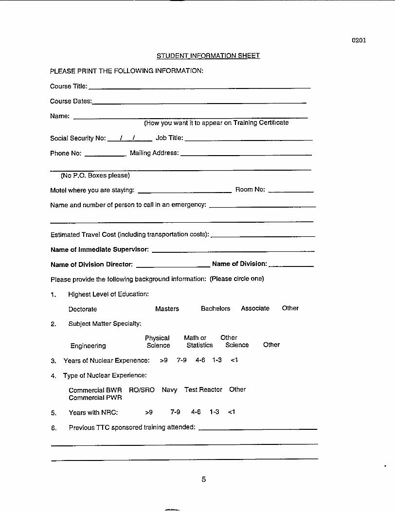
STUDENT INFORMATION SHEET
PLEASE PRINT THE FOLLOWING INFORMATION:
Course Title:
Course Dates:
Name:(How you want it to appear on Training Certificate
Social Security No: / I Job Title:
Phone No: Mailing Address:
(No P.O. Boxes please)
Motel where you are staying: Room No:
Name and number of person to call in an emergency:
Estimated Travel Cost (including transportation costs):
Name of Immediate Supervisor:
Name of Division Director: Name of Division:
Please provide the following background information: (Please circle one)
1. Highest Level of Education:
Doctorate Masters Bachelors Associate Other
2. Subject Matter Specialty:
Physical Math or CEngineering Science Statistics
3. Years of Nuclear Experience: >9 7-9 4-6 1-3
4. Type of Nuclear Experience:
Commercial BWR RO/SRO Navy Test ReactorCommercial PWR
5. Years with NRC: >9 7-9 4-6 1-3
6. Previous TTC sponsored training attended:
)therScience
<1
Other
Other
<1
.
5
0201
Course Objectives(R-104B)
The BWR/4 technology course is designed to provide the student with a general familiarity with the mechanical,instrumentation and control, and protective systems of the General Electric BWRI4 design. At the end of thiscourse each student should have achieved a basic understanding of the following:
* Major process systems, purposes, normal system configuration, and safety related flowpaths.
* Major process instrumentation systems terminology, including selected interlocks and protectionfunctions.
* PRA concerns in a change to the level of plant safety/risk as a result of system or componentunavailability.
7
0201
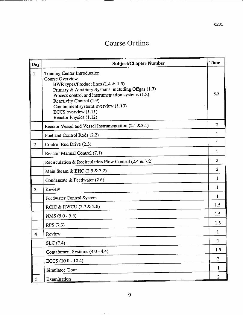
Course Outline
Day Subject/Chapter Number
Training Center IntroductionCourse Overview
BWR types/Product lines (1.4 & 1.5)Primary & Auxiliary Systems, including Offgas (1.7)Process control and instrumentation systems (1.8)Reactivity Control (1.9)Containment systems overview (1.10)ECCS overview (1.11)Reactor Physics (1.12)
Reactor Vessel and Vessel Instrumentation (2.1 &3.1)
Fuel and Control Rods (2.2)
2 Control Rod Drive (2.3)
Reactor Manual Control (7.1)
Recirculation & Recirculation Flow Control (2.4 & 7.2)
Main Steam & EHC (2.5 & 3.2)
Condensate & Feedwater (2.6)
3 Review
Feedwater Control System
RCIC & RWCU (2.7 & 2.8)
NMS (5.0 - 5.5)
RPS (7.3)
4 Review
SLC (7.4)
Containment Systems (4.0 - 4.4)
ECCS (10.0 - 10.4)
Simulator Tour
5 Examination
9

0201
10
0201
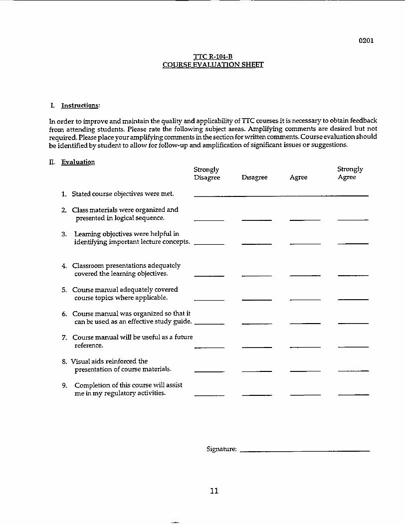
TTC R-104-BCOURSE EVALUATION SHEET
I. Instructions:
In order to improve and maintain the quality and applicability of TIC courses it is necessary to obtain feedbackfrom attending students. Please rate the following subject areas. Amplifying comments are desired but notrequired. Please place your amplifying comments in the section for written comments. Course evaluation shouldbe identified by student to allow for follow-up and amplification of significant issues or suggestions.
II. EvaluationStrongly StronglyDisagree Disagree Agree Agree
1. Stated course objectives were met.
2. Class materials were organized andpresented in logical sequence.
3. Learning objectives were helpful inidentifying important lecture concepts.
4. Classroom presentations adequatelycovered the learning objectives.
5. Course manual adequately coveredcourse topics where applicable.
6. Course manual was organized so that itcan be used as an effective study guide.
7. Course manual will be useful as a futurereference.
8. Visual aids reinforced thepresentation of course materials.
9. Completion of this course will assistme in my regulatory activities.
Signature:
11
0201
10. Overall course rating (considering merits of this course only):
Unsatisfactory Marginal Satisfactory Good
11. What did you like best or find most helpful about the course?
Excellent
12. What did you like least about the course?
13. What subjects might be added or expanded?
14. What subjects might be deleted or discussed in less detail?
15. How will this course aid you in your ability to do your job as a regulator?
16. What could be done to make this course more useful in aiding you in your ability to effectively carryoutyour regulatory activities?
17. Additional comments.
12
0201
Simulator Demonstration Instruction
A portion of this course may include demonstrations of system controls, indication, and operation on the
BWR/4 simulator, located on the fourth floor of this building. The class may be split into two or more
groups for these demonstrations. Due to the physical floor space limitations, it is important to stay in your
assigned group.
Simulator demonstrations are planned demonstrations coordinated by the instructor. Students should not
manipulate any switches on the simulator unless directed to by the instructor. The instructor console and
computer area are not normally accessible areas for students. For hardware considerations, please do not
place drinks on the simulator panels; ample desk area is available.
If the class is split into groups for simulator demonstrations, while one group is in the simulator, the other
group or groups will be on self study. The self study time is to be used for reading manual chapters,
review of material that has been presented, or if desired, review of material on an individual basis with
an instructor. If instructor assistance is needed, please use the telephone in the classroom to call one of
the course instructors. A telephone number list is attached beside the phone.
13
General Electric Technologv Manual Table of ContentsGeneral Electric Techno1a�v Manual Table of Contents
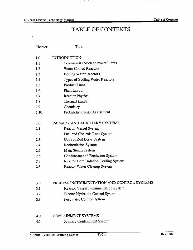
TABLE OF CONTENTS
Chapter Title
1.0 INTRODUCTION
1.1 Commercial Nuclear Power Plants
1.2 Water Cooled Reactors
1.3 Boiling Water Reactors
1.4 Types of Boiling Water Reactors
1.5 Product Lines
1.6 Plant Layout
1.7 Reactor Physics
1.8 Thermal Limits
1.9 Chemistry
1.10 Probabilistic Risk Assessment
2.0 PRIMARY AND AUXILIARY SYSTEMS
2.1 Reactor Vessel System
2.2 Fuel and Controls Rods System
2.3 Control Rod Drive System
2.4 Recirculation System
2.5 Main Steam System
2.6 Condensate and Feedwater System
2.7 Reactor Core Isolation Cooling System
2.8 Reactor Water Cleanup System
3.0 PROCESS INSTRUMENTATION AND CONTROL SYSTEMS
3.1 Reactor Vessel Instrumentation System
3.2 Electro Hydraulic Control System
3.3 Feedwater Control System
4.0 CONTAINMENT SYSTEMS
4.1 Primary Containment System
USNRC Technical Training Center ToC-i Rev 0102USNRC Technical Training Center ToC-i Rev 0102
General Electric Technology Manual Table of ContentsGeneral Electric Technology Manual Table of Contents
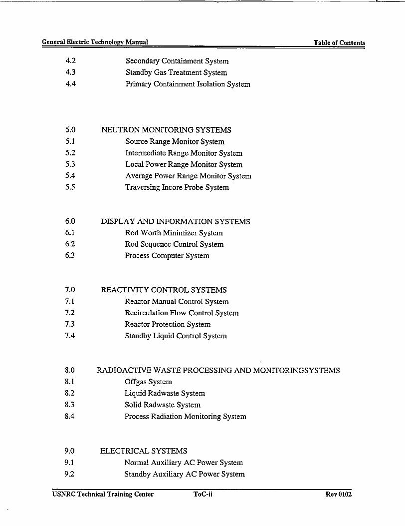
4.2 Secondary Containment System
4.3 Standby Gas Treatment System
4.4 Primary Containment Isolation System
5.0 NEUTRON MONITORING SYSTEMS
5.1 Source Range Monitor System
5.2 Intermediate Range Monitor System
5.3 Local Power Range Monitor System5.4 Average Power Range Monitor System
5.5 Traversing Incore Probe System
6.0 DISPLAY AND INFORMATION SYSTEMS6.1 Rod Worth Minimizer System6.2 Rod Sequence Control System
6.3 Process Computer System
7.0 REACTIVITY CONTROL SYSTEMS
7.1 Reactor Manual Control System7.2 Recirculation Flow Control System
7.3 Reactor Protection System
7.4 Standby Liquid Control System
8.0 RADIOACTIVE WASTE PROCESSING AND MONITORINGSYSTEMS
8.1 Offgas System
8.2 Liquid Radwaste System
8.3 Solid Radwaste System
8.4 Process Radiation Monitoring System
9.0 ELECTRICAL SYSTEMS
9.1 Normal Auxiliary AC Power System
9.2 Standby Auxiliary AC Power System
USNRC Technical Training Center ToC-ji Rev 0102USNRC Technical Training Center ToC-ii Rev 0102
General Electric Technolo~rv Manual Table of Contents(�ener3l Electric Technolo�v Manual Table of Contents
9.3 120VAC Power System
9.4 DC Power System
10.0 EMERGENCY CORE COOLING SYSTEMS
10.1 High Pressure Coolant Injection System
10.2 Automatic Depressurization System
10.3 Core Spray System
10.4 Residual Heat Removal System
11.0 WATER AND AIR SYSTEMS
11.1 Circulating Water System
11.2 Reactor Building Service Water System
11.3 Reactor Building Closed Loop Cooling Water System
11.4 Turbine Building Service Water System
11.5 Turbine Building Closed Loop Cooling Water System
11.6 Service and Instrument Air System
12.0 REACTOR OPERATIONS
12.1 Cold Startup Procedures
12.2 Normal Shutdown From Power
13.0 BWR DIFFERENCES
Appendices
A GLOSSARY OF TERMS
B PIPING AND INSTRUMENTATION SYMBOLS
C LIST OF COMMON ABBREVIATIONS
D PURPOSE AND OBJECTIVE SHEETS
USNRC Technical Training Center ToC-iji k(ev UiU�USNRC Technical Training Center ToC-iii Rev 0102
gepneral V.lect-rin Tpehnninav Manual Introduction('pnj.r�il I�1pp$r�r T�i4unn1nov M�,nin1 Introduction
1.0 INTRODUCTION
The GE Technology Manual is designed for use asa text for the GE Technology Course. The manualwas written to reflect the BWR design. Thenumerical values and systems discussed in themanual are for a specific BWR. The readershould bear this in mind when attempting to usethe manual as a general reference document.
1.0.1 Manual Organization
This manual has been organized to follow, asclosely as possible, the order of the materialpresented in the above course. General subjectareas are classified by chapters. Systems whichfall under the general classification are arrangedas sections within the chapter. Where applicableeach section follows the same format; i.e.,introduction, system description, componentdescription, system features and interrelations,summary, and graphics.
The manual also has appendices containingdefinitions, symbols, abbreviations and a BWRTechnology Course Syllabus, Outline and Purposeand Objective Sheets. Following completion ofthe instructors presentation and self-study, thestudent should be able to exhibit knowledge ofthese objectives.
1.0.1.1 System Introduction
The system introduction states the system purposeand functional classification. The purpose of theintroduction is to orient the reader.
1.0.1.2 System Description
The system description provides the reader withan overview of the system and its components.Attention is focused on major components andtheir purposes without including the detail foundin the component description.
1.0.1.3 Component Description
The components are listed in basic flow pathorder or block diagram arrangement. Eachcomponent is described in appropriate detail withspecific set points and capacities often referencedin tables.
1.0.1.4 System Features and Interrelations
The system features and interrelations sectionincludes such items as the operational features andlimitations. It also identifies interfaces with othersystems.
1.0.1.5 Summary
The summary is designed to key the reader to themajor items contained in the chapter. It isimportant for the reader to recognize that thesummary is not a substitute for a comprehensivereview of the text material.
1.0.1.6 Graphics
The graphic package is located at the end of eachsection. The graphics are arranged to follow thetext and are referenced in the written portion ofthe text.
1.0.2 Manual Use During CoursePresentation
Proper use of the manual during classpresentations can greatly aid the student inunderstanding the material presented. The studentshould follow the presentation using the figuresand diagrams provided. Properly noting minorand major points on these figures should eliminatethe necessity for taking comprehensive notesduring the lecture.
USNRC Technical Training Center 1.0-1 KeY IJIW)USNRC Technical Training Center 1.0-1 Key 0100
General Flectric Technologv Manual Commercial Nuclear Power PlantsCener2l Electric Technolo�v Manual Commercial Nuclear Power Plants
1.1 COMMERCIAL NUCLEAR POWERPLANTS
To understand the BWR power plant, a basicknowledge of the major components and theirfunctions is needed.
1.1.1 Nuclear Power Plants
A nuclear power plant is an arrangement ofcomponents and systems used to generate heat.The heat is used to make steam which isconverted to electrical power. The principalcomponents of a nuclear power plant are:
* nuclear fuel and moderator* heat removal system* control systems* power conversion systems
1.1.2 Nuclear Fuel and Moderator
Nuclear fuel consists of a mixture of fissionableand fertile materials. The essential ingredient is afissionable material, which is a material thatreadily undergoes nuclear fission when struck byneutrons. The only naturally available fissionablematerial is uranium-235 (U-235), an isotope (orform) of uranium constituting less than 1 % of theelement as found in nature. Two syntheticfissionable materials are plutonium-239 (Pu-239)and uranium-233 (U-233). When neutrons strikeuranium-238 (U-238), which constitutes morethan 99% of the natural uranium, Pu-239 isformed. For this reason U-238 is called a "fertile"material. The element thorium is also a fertilematerial, forning U-233 when struck by aneutron. The three basic fissionable materialsmay be used separately or with one of the fertilematerials as fuel for a nuclear reactor.
Fuels may be solid or fluid and they may be usedin different material forms: metals, alloys, oxides,or salts. A variety of solid fuel physicalshapes isused, including rods, plates, tubes, and othershapes, along with various methods for cladding(containing) the fuel. A moderator is a substanceused in a reactor to slow down neutrons from highto low energy levels. Slowing down increases theprobability of continued fission. Moderatorscommonly used include ordinary water, heavywater, and graphite. Liquid moderators can alsoserve as the coolant.
1.1.3 Heat Removal System
The heat removal system or cycle removes heatwhich is generated by the fission process in thereactor core. Heat removal system arrangementsinclude single, double, and triple heat transfercycles. An example of the single cycle system isthe direct cycle boiling water reactor deliveringsteam to a turbine. Pressurized water reactors usetwo cycles, with the primary water transferringheat in a steam generator to produce steam for theturbine cycle.
1.1.4 Control Systems
In the general sense of the term, there arenumerous control systems on modem reactors.The specific control system of concern here isreactivity control, which is the method by whichthe reactor core fission process is regulated. Thebasic method of accomplishing this regulation isto insert a neutron poisoning or absorbing materialinto the reactor core, thereby preventing thoseneutrons absorbed in the poison from causingfission in the fuel. There are other methods, someof which are specific to the BWR, which arediscussed later in this text.
The most commonly used fuel is uranium, eithernatural, or enriched in the U-235 isotope.
USNRC Technical Training Center 1.1-1 Rev 0100USNRC Technical Training Center 1.1-1 Rev 0100
General Electric Technology Manual Commercial Nuclear Power PlantsGeneral Electric TechnoIo�v Manual Commercial Nuclear Power Plants
1.1.5 Power Conversion Systems
In modem reactor power plants, steam turbinegenerators are used to convert the energy of thesteam into electrical power.
USNRC Technical Training Center 1.1-2 Rev 0100USNRC Technical Training Center 1.1-2 Rev 0100
General Electric Technology Manual Water Cooled ReactorsGeneral Electric Technolacv Manual Water Cooled Reactors
1.2 WATER COOLED REACTORS
Water is generally used as a coolant and amoderator for power reactors. Initially it wasbelieved that water could not be permitted to boilin a reactor vessel because of the possibility ofcladding burnout. This resulted in the earlydevelopment of pressurized water reactors. Thefirst pressurized water reactor went critical in1953 at the AEC National Reactor Testing Stationin Idaho
A different type of water cooled and watermoderated reactor was started in 1953 with thefirst experiment to test the theory of boiling waterin a reactor vessel and making steam directly.Successive experiments established the principlethat boiling was not only acceptable but evenadvantageous for certain purposes.
It is only natural that water became the preferredprimary reactor coolant. Reliability is a key factorand water has many important advantages that donot require extensive experimental programs.Water is a known quantity. It is cheap, and it wasreadily available when the reactor program wasstarted. It has good heat transfer characteristicswhich can be extended beyond its normal narrowtemperature range by pressurizing the water toinhibit boiling. Furthermore, water does notbecome significantly activated if kept pure. Theinduced radioactivity of the coolant is short livedso that maintenance is not hampered greatly.
highly corrosive and requires that the primarycoolant system be constructed of specialmaterials; water at high pressure and saturationtemperature will flash to steam if the pressure israpidly reduced, as in a rupture of the primaryloop; and water can chemically react violentlyunder certain temperature conditions withuranium, thorium, and structural materials.
The fundamental similarity in nuclearcharacteristics of water moderated reactors isdetermined basically by the nuclear and thermalproperties of light water. Briefly, thesesimilarities can be summarized as follows:
* Enriched fuel is required.* Relatively low moderator to fuel ratios are
employed.* Relatively high excess reactivity is provided.* Conversion ratios for existing types are low,
but this is not an inherent characteristic.* Power densities are comparatively high.
The corrosive quality of water is known, and thepressurizing intensifies the corrosive action. Animportant inducement is that water serves as amoderator to slow down the neutrons; Itstendency to absorb neutrons can be overcome byenriching the fuel.
The disadvantages of using water as a moderatorare: water must be highly pressurized to achievereasonably high temperatures; pure hot water is
USNRC Technical Training Center 1.2.1 Rev 0100USNRC Technical Training Center 1.2-1 Rev 0100
General Electric Technologv Manual B~oiline Water ReactorsGeneral Electric Tecbnolo2v Manual Boiinn Water Reactors
1.3 BOILING WATER REACTORS
In a boiling water reactor, the coolant is very purewater which boils adjacent to the fuel elements.The resulting steam-water mixture then proceedsto steam separators, where the water is separatedfrom the steam bubbles. The water then goesback to the reactor core and the boiling operationis repeated. The steam which is formed passesfrom the steam separators, through the steamdryers, and to a turbine located outside thecontainment.
The major difference in the operatingcharacteristics of a boiling water reactor core fromother nuclear systems is a result of steam voidproduction. Water affects both the heatgeneration and the neutron flux characteristics ofa nuclear system because it serves the dualfunction of coolant and neutron moderator. If thiswater is allowed to boil, which greatly lowers thedensity of molecules, there is a significant changein nuclear performance. The boiling water reactordesign results in a system that produces reactivitychanges varying inversely with the steam voidcontent in the core. This provides an inherentsafety feature of the boiling water reactor; that is,a transient power increase will produce moresteam voids, reducing reactivity, which reducespower and thus limits the excursion.
The fuel used in a boiling water reactor containsuranium in the form of an oxide. This eliminatesthe hazard involved in using uranium in metallicform. Moreover, before assembly into fuelelements, the uranium oxide is generally heatedand converted into a ceramic material, somewhatlike the bricks used to line fireplaces. This formof uranium oxide does not react chemically withthe reactor coolant and does not bum in air.
USNRC Technical Training Center 1.3.1 Rev 0100USNRC Technical Training Center 1.3-1 Rev 0100
tt.nesllF~eetieTderh1nnlncrv Mniiila Tvyes of BWR's
1.4 TYPES OF BOILING WATER system in the makeup water. The turbine cycle
REACTORS uses a conventional regenerative feedwatersystem. The feedwater temperature and the
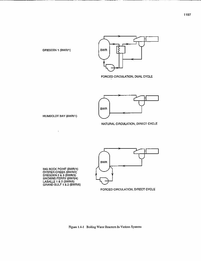
In direct cycle BWRs, as shown in Figure 1.4-1, number of feedwater heaters are selected in
steam leaving the reactor passes directly to the accordance with normal power plant
turbine. In an indirect cycle BWR, steam is considerations of turbine cycle performance and
passed to a primary coolantlsecondary steam economics.generator. No economic incentive exists for thelatter cycle, although it does possess some 1.4.1 Forced Circulation BWRsadvantage in that radioactive particles from theprimary coolant normally cannot transfer to the Power density in a BWR core may be increased
steam used in the turbine generator portion of the by using a mechanical pumping system to forceplant. Dual cycle plants employ a combination of the water through the core. This is called a forceddirect and indirect cycles. The first large utility circulation BWR. In this design a portion of theowned BWR (Dresden 1) employed this dualcycle concept. Current BWRs use only the forced coolant in the annulus area between the corecirculation direct cycle because it is more shroud and vessel wall is taken outside the vessel
economical. in recirculation loops, where it is increased in
pressure by means of recirculation pumps. WaterIn a forced circulation direct cycle reactor system, at increased pressure is pumped from the twothe nuclear fuel generates heat within the reactor recirculation loops back into the bottom of thevessel and boils the water, producing wet steam reactor press back ia t pum owthat passes through internal steam separators and reactor pressure vessel via jet pumps. Flowdryers. The water within the reactor is circulated orificing of the fuel support pieces provides
through the core by two external recirculation desired flow distributions. Water enters the core
pumps. The steam is directed from the reactor to through the fuel assembly nosepieces and passesthe turbine, entering the turbine steam chest at upward inside the channels containing the fuelabout 950 psi and 54OoF. Steam leaving the high bundles, where it is heated to become a two phase,pressure turbine passes through moisture separator steam-wher ituis he team e a itureunits before being admitted to the low pressure steam-water mixture. The steam-water mixtureturbines. leaves the top of the fuel assemblies and enters a
plenum area above the core which directs the flow
The low pressure turbines exhaust steam is into the steam separators. Here the water iscondensed in the main condenser, which also separated by centrifugal action. The rejectedprovides system deaeration. The condenser is water is returned to recirculate through thefollowed by a full flow demineralizer system e
through which all condensate and makeup must pumping system. The steam then passes through
pass before entering the feedwater heaters. a dryer where the last traces of water are removed.Dry steam exits through steam outlet nozzles at
The demineralizer system removes corrosion the top of the vessel body. Feedwater is added toproducts produced in the turbine, condenser, and the system through thermally sleeved spargersfeedwater piping. It also protects the reactoragainst condenser tube leaks and removes other located in the waoer annulus. Hr thesources of impurities which may enter the feedwater joins the water rejected by the steam
USNRC Technical Training Center 1.4-1 k(ev uIuuUSNRC Technical Training Center 1.4-1 Rev 0100
General Electric Technology Manual Types of BWR'sGeneral Electric Technology Manual Types of BWR's
separators before entering the recirculation
pumping system.
1.4.1.1 Forced Circulation BWR Control
Systems
The fluid flow rates and reactivity level in a
forced circulation direct cycle BWR require rigid
control of steam flow from the reactor, of
feedwater flow into the reactor, of recirculation
flow through the reactor, and of control rod
position. The design of the control systems
considers conventional power generation
objectives, such as reliability, ease of operation,and response times of the controlling parameter.
Beyond the traditional power generation
objectives, the control systems must incorporatefeatures specific to reactivity control and nuclear
plant safety. These considerations involve effects
on moderator temperature, fuel temperature, and
void content as a function of steam pressure;
steam generation and feedwater input; fuel
exposure; and automatic shutdown of the nuclear
chain reaction during unsafe or potentially unsafe
conditions.
USNRC Technical Training Center 1.4-2 Rev 0100USNRC Technical Training Center 1.4-2 Rev 0100
1197
DRESDEN 1 (BWR'1)
FORCED CIRCULATION, DUAL CYCLE
HUMBOLDT BAY (BWR/1)
NATURAL CIRCULATION, DIRECT CYCLE
BIG ROCK POINT (BWRI1)OYSTER CREEK (BWR/2)DRESDEN 2 & 3 (BWR/3)BROWNS FERRY (BWR/4)LASALLE 1 & 2 (BWR/5)GRAND GULF 1 & 2 (BWR/6)
FORCED CIRCULATION, DIRECT CYCLE
Figure 1.4-1 Boiling Water Reactors In Various Systems
General Electric Technology Manual Product LinesGeneral Electric Technology Manual Product Lines
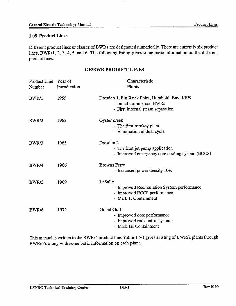
1.05 Product Lines
Different product lines or classes of BWRs are designated numerically. There are currently six productlines, BWR/1, 2, 3, 4, 5, and 6. The following listing gives some basic information on the differentproduct lines.
GE/BWR PRODUCT LINES
Product Line Year of CharacteristicNumber Introduction Plants
BWR/1 1955 Dresden 1, Big Rock Point, Humboldt Bay, KRB- Initial commercial BWRs- First internal steam separation
BWR/2 1963 Oyster creek- The first turnkey plant- Elimination of dual cycle
BWR/3 1965 Dresden 2- The first jet pump application- Improved emergency core cooling system (ECCS)
BWR/4 1966 Browns Ferry- Increased power density 10%
BWR/5 1969 LaSalle- Improved Recirculation System performance- Improved ECCS performance- Mark II Containment
BWR/6 1972 Grand Gulf- Improved core performance- Improved rod control systems- Mark HI Containment
This manual is written to the BWR/4 product line. Table 1.5-1 gives a listing of BWR/2 plants throughBWR/6's along with some basic information on each plant.
USNRC Technical Training Center 1.05-1 Rev 0100USNRC Technical Training Center 1.05-1 Rev 0100
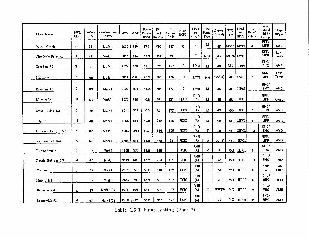
I3WR Product Containment MWT MWE Denity Fuel Control IC or o upBps RFC orPC NO.i Control *TypeRCIC o PupCapacity Type CntS / Ofa
Plant Name Cml7a Line *Type KW/L Bundles Rods RIIR *4 Typepe e C Valves Backup -
EPR/
Oyster Creek 2 63 Mark I 1930 620 33.6 560 137 IC _ M 45 MG*5 FWCI 4 MPR AME
EPR/ Low
Nine Mile Point #1 2 63 Mark l 1850 620 34.0 532 129 IC M&T 45 MG*5 FWCI 6 MPR Temp
EHC/Dresden #2 3 65 Mark I 2527 809 41.08 724 177 IC LPCI M 45 MG HPCI 5 EHC AMB
_ _EPR/ LowMillstone 3 65 Mark I 2011 690 40 08 580 145 IC LPCI 100w(3 MG EWCI 3 EHC Temp
EHC/Dresden #3 3 66 Mark I 2527 809 41.08 724 177 IC LPCI M 45 MG TIPCI 6 EHC AMB
RHR EPR/Monticello 3 66 Mark I 1670 545 40.6 484 121 RCIC (A) M 15 MG HPCI 4 MPR Comp
RHR EHC/Quad Cities 1/2 3 66 Mark I 2511 809 40.9 724 177 RCIC (A) M 45 MG HPCI S EHC AMB
RHR IEPR/hlgrmn 3 66 Mark l 1998 655 40.5 580 145 RCIC (A) M 26 MG HPCI 4 MPR AMB
RH-R EHC/Brown's Ferry 1/2/3 4 67 Markl1 3293 1065 50.7 764 185 RCIC (A) T 26 MG HPCI 13 EHC AMB
RHR EPR/Vermont Yankee 4 67 Markl 1593 514 51.0 368 89 RCIC (A) M 100^(3) MG IIPCI 4 MPR AMB
RHR EHC/Duane Arnold 4 67 Mark ! 1658 538 51.0 368 89 RCIC (A) M 26 MG HPCI 6 EHC AMB
RHR EHC/Peach Bottom 2/3 4 67 Mark I 3293 1065 50.7 764 185 RCIC RHR T 26 MG HPCI 11 EHC Comp
RHR Digital Low
Cooper 4 67 Mark 1 2381 778 50.6 548 137 RCIC (A) T 26 MG HPCI 8 (W) Temp
RHR EHC/
Hatch 1/2 4 67 Mark I 2436 786 51.2 560 137 RCIC (A) T 26 MG HPCI 9 EHC AMB
RHR EH-CIBrunswick 01 67 Mark I (C) 2436 821 51.2 560 137 RCIC (A) T 100*(3) MG HPCI 9 EHC AMB
RHR EHC/Brunswick 02 4 67 Mark I(C) .2436 1821 .51.2 560 137 RCIC (A) T 26 MG HPI 9 EHC IAMB
Table 1.5-1 Plant Listing (Part 1)

Press.BWR Product Containment MWT MWE Power NO. NO. IC or LPCI Feed BIPCI NO. Control *TypePlant Name Class Line *Type Kesiyf OdeI Cnrol ByCor Pm Cpacis RypC or Reief liiitial / Offgas
Densit FBund ontro oosrH Pum Capaciy T pe S Valves B,~
RIIR EHICI
Fi17patrick 4 67 Mark I 2436 821 51.2 560 137 RCIC (A) T 26 MC IIIPCI 9 EIIC AMR
R111R EII1C/Enrico Fermi 4 67 Mark 3293 1093 50 0 764 185 RCIC (A) T 26 MG HPCI 1 L IIC/ AMD
RIIR EIIC/llope Creek 4 67.5 Mark I 3293 1067 50.7 764 185 RCIC (C) T 26 MG IlPCI I_ EIIC AMD
RIlR EIIC/Susquehanna 1/2 4 67.5 Mark 11 (C) 3293 1050 50.0 764 185 RCIC (A) T 25 MG IIPQI 16 EIIC AME
RlIR EIIC/Shorcham 4 67.5 Mark 11 (C) 2436 821 50 0 560 137 RCIC (A) T 26 MG IIPCI 9 El IC AMb
RHiR 111IC/
Limerick 1/2 4 67.5 Mark 11 (C) 3293 1065 50.7 764 185 RCIC (C) T 26 MG IIPCI 11 EIIC AMB
RI111 EIlC/LaSalle 1/2 5 69 Mark 11 (C) 3293 1078 50 0 764 185 RCIC (B) T 25 Valve IIPCS 11 EIIC AMB
Rl IR Digital Lowllanford #2 5 69 Mark1l 3323 1100 50 0 764 185 RCIC (B) T 25 Valve IIPCS 18 (W) Temp
RIHR EIRC/Nine Mile Point #2 5 69 Mark 11 (C) 3323 1100 50 0 764 185 RCIC (B) T 25 Valve IIPCS 18 EIIC AMB
R1IR FE!IC/ LowGrand Gulf 6 72 Mark III (C) 3835 1306 54.1 800 193 RCIC (B) T 35 Valve IIPCS 20 EIIC Temp
RIIR EIIC/ LowPerry 6 72 Mark= i 3579 1200 56 0 748 177 RCIC (B) M/T 35 Valve IIPCS 19 ElIIC Temp
RIIR LiIC/ LIowClinton 6 72 Mark III (C) 2894 995 52 4 624 145 RCIC (B) M/T 35 Valve IIPCS 16 EIIC Temp
RIIC I EIIC/ LowRiver Dend] 6 72 MarkIII 284 95 152.4 1624 1145 1RCIC I(B) M 10 Valve 1IC 1 I IC Tm
Notes- 1. Mark !: Drywell - Torus (Freestanding Steel Pressure Vessel)Mark I (C) Drywell - Torts (Concrete with Steel Liner);Mark II Over/Under (Freestanding Steel Pressure Vessel);Mark 11 (C): Over/tJnder (Concrete With Steel Liner);Mark IlI Drywell - Containment (Freestanding Containment Vessel;Mark Ill (C) Drywell - Containment (Concrete Containment With Steel Liner).
2. AMB Recombiner - with Charcoal Beds at Ambient TemperatureLow Temp Recombiner - with Charcoal Beds at Low Temperature(Zero degrce f)Comp Recombiner - with Comperssor and Storage Tanks for Extended Gas hfoldup
3 Equipped with a Select Rod Insert Function4. (A) Equipped with 2 RIIR Loops, LPCI Mode Injects to the Recirculation System
(B) Equipped with 3 RIIR Loops, LPCI Mode Injects Directly to the Vessel(C) Equipped with 4 RI IR Loops, LPCI Mode Injects Directly to the Vessel
5. Equipped with 5 Recirculation Loops and No let Pumps
Table 1.5-1 Plant Listing (Part 2)
General Electric Technology Manual Plant LayoutGeneral Electric Technology Manual Plant Layout
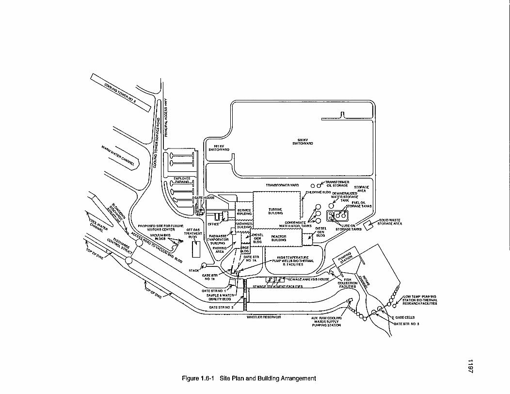
1.06 PLANT LAYOUT
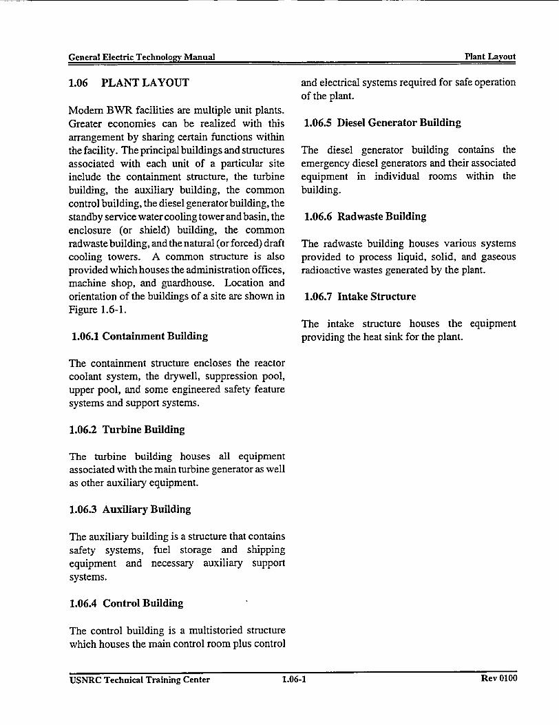
Modem BWR facilities are multiple unit plants.Greater economies can be realized with thisarrangement by sharing certain functions withinthe facility. The principal buildings and structuresassociated with each unit of a particular siteinclude the containment structure, the turbinebuilding, the auxiliary building, the commoncontrol building, the diesel generator building, thestandby service water cooling tower and basin, theenclosure (or shield) building, the commonradwaste building, and the natural (or forced) draftcooling towers. A common structure is alsoprovided which houses the administration offices,machine shop, and guardhouse. Location andorientation of the buildings of a site are shown inFigure 1.6-1.
1.06.1 Containment Building
and electrical systems required for safe operationof the plant.
1.06.5 Diesel Generator Building
The diesel generator building contains theemergency diesel generators and their associatedequipment in individual rooms within thebuilding.
1.06.6 Radwaste Building
The radwaste building houses various systemsprovided to process liquid, solid, and gaseousradioactive wastes generated by the plant.
1.06.7 Intake Structure
The intake structure houses the equipmentproviding the heat sink for the plant.
The containment structure encloses the reactorcoolant system, the drywell, suppression pool,upper pool, and some engineered safety featuresystems and support systems.
1.06.2 Turbine Building
The turbine building houses all equipmentassociated with the main turbine generator as wellas other auxiliary equipment.
1.06.3 Auxiliary Building
The auxiliary building is a structure that containssafety systems, fuel storage and shippingequipment and necessary auxiliary supportsystems.
1.06.4 Control Building
The control building is a multistoried structurewhich houses the main control room plus control
USNRC Technical Training Center 1.06-1 Rev U1UIJUSNRC Technical Training Center 1.06-1 Rev U1UU
00 KVSWITCHYARD
TEMP PUMPING
AUX RAW COOLINGWATER SUPPLY
PUMPING STATION NO 3
-L
Figure 1.6-1 Site Plan and Building Arrangement
General Electric Technology Manual Primary & Auxiliary SystemsGeneral Electric Technolo�v Manual Primary & Auxiliary Systems
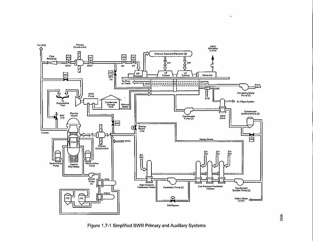
1.7 BWR PRIMARY AND AUXILIARYSYSTEMS
The BWR primary and auxiliary systems are theones which are immediately involved in the directcycle BWR concept as part of the steam cycle orelse provide an auxiliary function for the directcycle system. These systems are graphicallydisplayed in Figure 1.7-1. The BWR direct steamcycle starts with the reactor vessel which is part ofthe reactor coolant pressure boundary and whichcontains the reactor core. The reactor coreprovides the heat source for steam generation andconsists primarily of the nuclear fuel and controlrods for regulating the fission process. The steamgenerated in the reactor vessel is routed to thesteam loads and then condensed into water. Thewater is then purified, heated, and pumped back tothe reactor vessel to again be heated. Water fromthe reactor vessel is circulated through externalpumping loops and then returned to the reactorvessel to provide forced circulation of flowthrough the reactor core. Reactor water iscontinuously purified to minimize impurities.Should the reactor become isolated from its mainheat sink, an auxiliary system automaticallymaintains the reactor core covered with water.The BWR primary and auxiliary systems arebriefly discussed in the paragraphs that follow.
1.7.1 Reactor Vessel System
The Reactor Vessel System houses and supportsthe reactor core; provides water circulation to thereactor core to remove generated heat; separatesthe water and steam produced in the reactor coreand delivers dry steam to the Main Steam System;and provides an internal, refloodable volume toassure core cooling capability following a loss ofcoolant accident (LOCA).
1.7.2 Fuel and Control Rods System
The fuel generates energy from the nuclear fissionreaction to provide heat for steam generation.
The control rods control reactor power level,control reactor power distribution, and provideemergency shutdown capability.
1.7.3 Control Rod Drive System
The Control Rod Drive System positions controlrods within the reactor core to change reactorpower or to rapidly shutdown the reactor
1.7.4 Recirculation System
The Recirculation System provides forcedcirculation of water through the reactor core,permitting higher reactor power than with naturalcirculation.
1.7.5 Main Steam System
The Main Steam System directs steam from thereactor vessel to the main turbine and other steamloads and provides overpressure protection for thereactor coolant system.
1.7.6 Condensate and Feedwater System
The Condensate and Feedwater System condensessteam and collects drains in the main condenser,purifies, preheats, and pumps water from the maincondenser to the reactor vessel.
1.7.7 Reactor Core Isolation Cooling System
The Reactor Core Isolation Cooling Systemprovides makeup water to the reactor vessel forcore cooling when the main steam lines are
USNRC Technical Training Center 1.7-1 Rev 0100USNRC Technical Training Center 1.7-1 Rev 0100
General Electric Technology Manual Primary & Auxiliary SystemsGeneral Electric Technolo�ty Manual Primary & Auxiliary Systems
isolated or when the Condensate and FeedwaterSystem is not available.
1.7.8 Reactor Water Cleanup System
The Reactor Water Cleanup System maintainsreactor water quality by filtration and ionexchange and provides a path for removal ofreactor coolant when required.
USNRC Technical Training Center 1.7-2 Rev 0100USNRC Technical Training Center 1.7-2 Rey 0100
PrimaryContainment 24KV
880 MWeto Grid
From
StartupReclrcLine
4 Lines
Low Pressure FeedwaterHeaters
SItu Bypass
00
Figure 1.7-1 Simplified BWR Primary and Auxiliary Systems
General Electric Technology Manual Process Instrumentation & Control SystemsGene�� Electric Technolo2v Manual Process Instrumentation & Control Systems
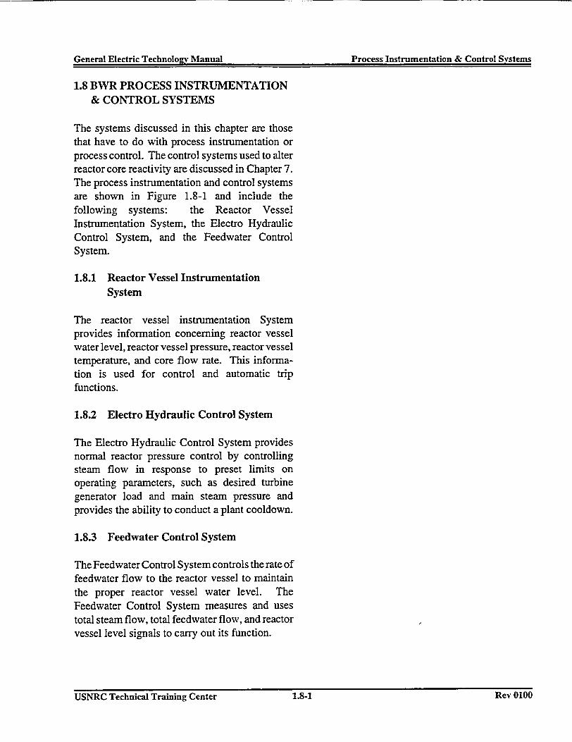
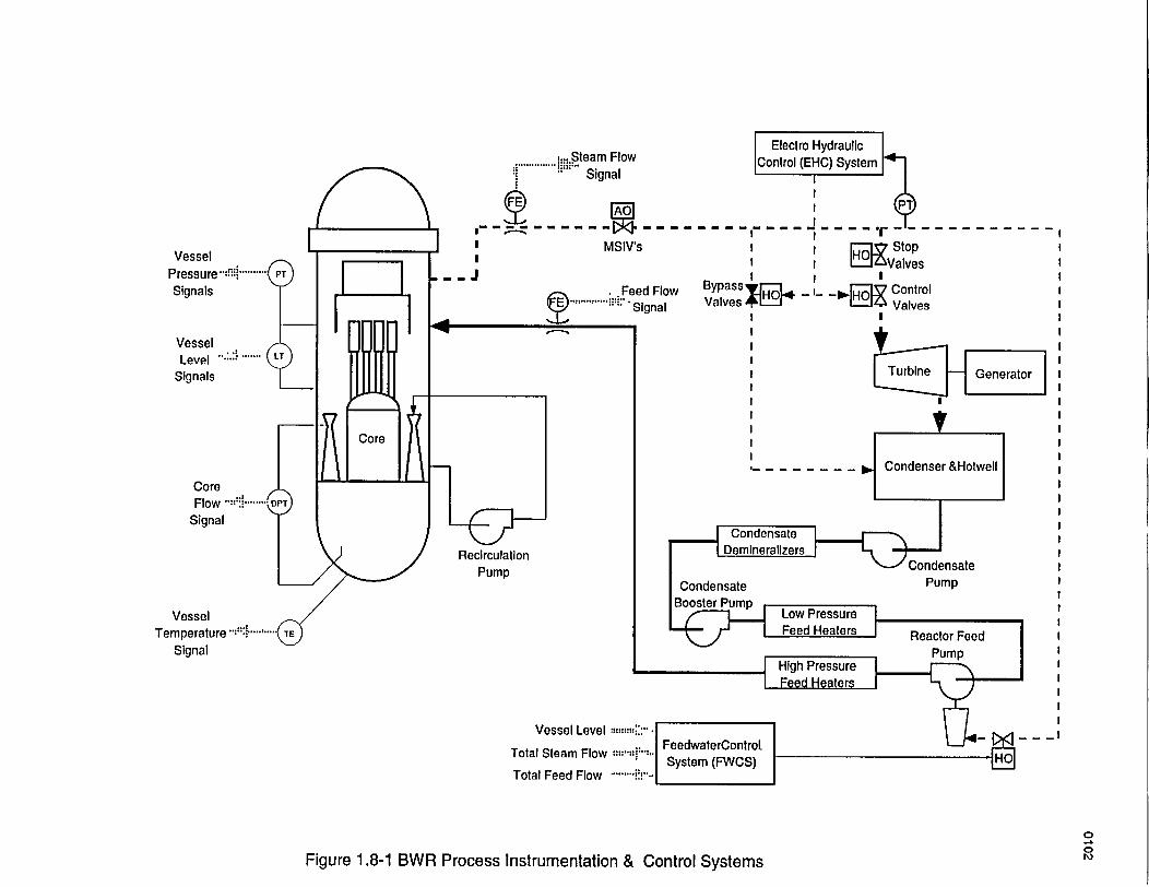
1.8 BWR PROCESS INSTRUMENTATION& CONTROL SYSTEMS
The systems discussed in this chapter are thosethat have to do with process instrumentation orprocess control. The control systems used to alterreactor core reactivity are discussed in Chapter 7.The process instrumentation and control systemsare shown in Figure 1.8-1 and include thefollowing systems: the Reactor VesselInstrumentation System, the Electro HydraulicControl System, and the Feedwater ControlSystem.
1.8.1 Reactor Vessel InstrumentationSystem
The reactor vessel instrumentation Systemprovides information concerning reactor vesselwater level, reactor vessel pressure, reactor vesseltemperature, and core flow rate. This informa-tion is used for control and automatic tripfunctions.
1.8.2 Electro Hydraulic Control System
The Electro Hydraulic Control System providesnormal reactor pressure control by controllingsteam flow in response to preset limits onoperating parameters, such as desired turbinegenerator load and main steam pressure andprovides the ability to conduct a plant cooldown.
1.8.3 Feedwater Control System
The Feedwater Control System controls the rate offeedwater flow to the reactor vessel to maintainthe proper reactor vessel water level. TheFeedwater Control System measures and usestotal steam flow, total feedwater flow, and reactorvessel level signals to carry out its function.
USNRC Technical Training Center 1.8-1 Rev 0100USNRC Technical Training Center 1.8-1 Rev 0100
:... Steam Flow
.__ .... __ ........ ..
Signal
II --- 1 *----
I MSIV'sIVessel
Pressure -:'.-:Signals
VesselLevel . .......
Signals
CoreFlow :
Signal
VesselTemperature ..d: I
Signal
IIFE
- - 9. Feed Flow Bypass I I -
).......:'' Signal Valves HI I
> i
]B StopDO Valves
,O Valves
e&Ht well
ldensateIhump I
Actor Feed | I
m I
~I
A_ _ _ _I
RecirculationPump
Vessel Level
Total Steam Flow
Total Feed Flow
0
0Figure 1.8-1 BWR Process Instrumentation & Control Systems
General Electric Technology Manual Reactivitv Control FeaturesGeneral Electric TechnoloEv Manual Reactivity Control Features
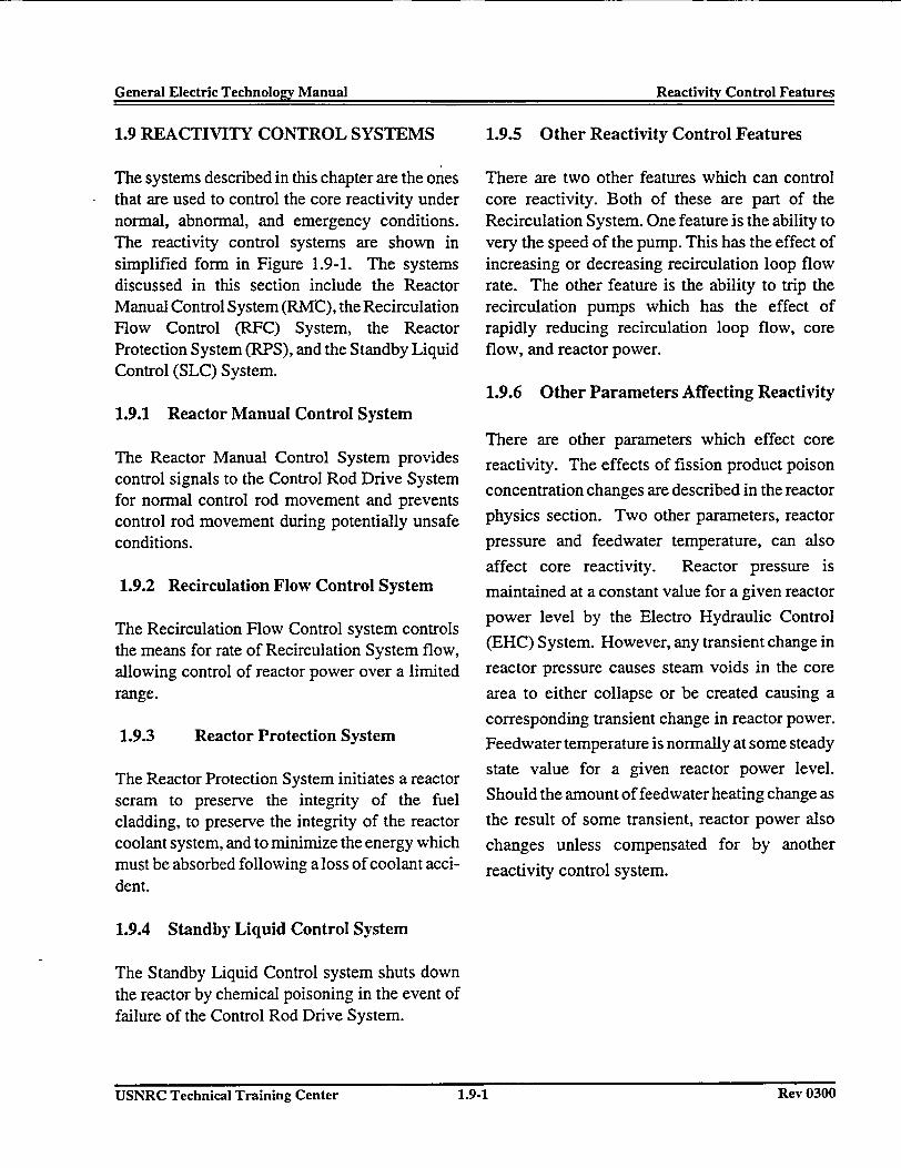
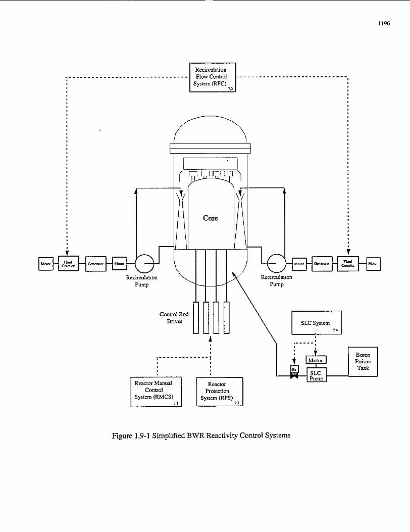
1.9 REACTIVITY CONTROL SYSTEMS
The systems described in this chapter are the ones* that are used to control the core reactivity under
normal, abnormal, and emergency conditions.The reactivity control systems are shown insimplified form in Figure 1.9-1. The systemsdiscussed in this section include the ReactorManual Control System (RMC), the RecirculationFlow Control (RFC) System, the ReactorProtection System (RPS), and the Standby LiquidControl (SLC) System.
1.9.1 Reactor Manual Control System
The Reactor Manual Control System providescontrol signals to the Control Rod Drive Systemfor normal control rod movement and preventscontrol rod movement during potentially unsafeconditions.
1.9.2 Recirculation Flow Control System
The Recirculation Flow Control system controlsthe means for rate of Recirculation System flow,allowing control of reactor power over a limitedrange.
1.9.3 Reactor Protection System
The Reactor Protection System initiates a reactorscram to preserve the integrity of the fuelcladding, to preserve the integrity of the reactorcoolant system, and to minimize the energy whichmust be absorbed following a loss of coolant acci-dent.
1.9.5 Other Reactivity Control Features
There are two other features which can controlcore reactivity. Both of these are part of theRecirculation System. One feature is the ability tovery the speed of the pump. This has the effect ofincreasing or decreasing recirculation loop flowrate. The other feature is the ability to trip therecirculation pumps which has the effect ofrapidly reducing recirculation loop flow, coreflow, and reactor power.
1.9.6 Other Parameters Affecting Reactivity
There are other parameters which effect core
reactivity. The effects of fission product poison
concentration changes are described in the reactor
physics section. Two other parameters, reactor
pressure and feedwater temperature, can also
affect core reactivity. Reactor pressure is
maintained at a constant value for a given reactor
power level by the Electro Hydraulic Control
(EHC) System. However, any transient change in
reactor pressure causes steam voids in the core
area to either collapse or be created causing a
corresponding transient change in reactor power.
Feedwater temperature is normally at some steady
state value for a given reactor power level.
Should the amount of feedwater heating change as
the result of some transient, reactor power also
changes unless compensated for by another
reactivity control system.
1.9.4 Standby Liquid Control System
The Standby Liquid Control system shuts downthe reactor by chemical poisoning in the event offailure of the Control Rod Drive System.
USNRC Technical Training Center 1.9-1 Rev 0300USNRC Technical Training Center 1.9-1 Rev 0300
1196
Recirculation_ _ _ _ _ _ _ _ _ _ _ _ _ -_Flow Control -------------- -- --------------
* System (RFC)
a 7
af A
Recirculao\v Recirculationpump _\Pump
Control Rod [1[11Daves SS System
a7 4
Reactor Manual ReactorControl Protection
System (RMCS) System (RPS)
Figure 1.9-1 Simplified BWR Reactivity Control Systems
General Electric TechnoloL-v Manual Containment SystemsGeneral Electric Technolo�v Manual Containment Systems
1.10 CONTAINMENT SYSTEMS
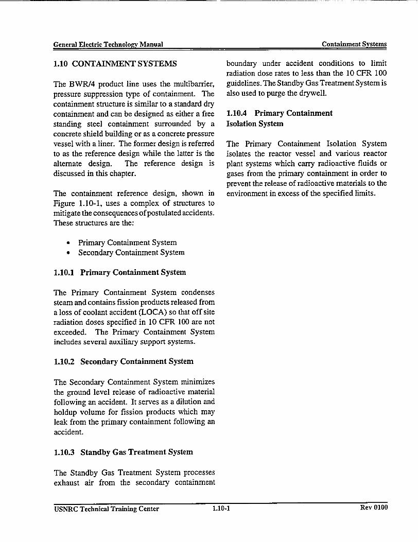
The BWR/4 product line uses the multibarrier,pressure suppression type of containment. Thecontainment structure is similar to a standard drycontainment and can be designed as either a freestanding steel containment surrounded by aconcrete shield building or as a concrete pressurevessel with a liner. The former design is referredto as the reference design while the latter is thealternate design. The reference design isdiscussed in this chapter.
The containment reference design, shown inFigure 1.10-1, uses a complex of structures tomitigate the consequences of postulated accidents.These structures are the:
boundary under accident conditions to limitradiation dose rates to less than the 10 CFR 100guidelines. The Standby Gas Treatment System isalso used to purge the drywell.
1.10.4 Primary ContainmentIsolation System
The Primary Containment Isolation Systemisolates the reactor vessel and various reactorplant systems which carry radioactive fluids orgases from the primary containment in order toprevent the release of radioactive materials to theenvironment in excess of the specified limits.
* Primary Containment System* Secondary Containment System
1.10.1 Primary Containment System
The Primary Containment System condensessteam and contains fission products released froma loss of coolant accident (LOCA) so that off siteradiation doses specified in 10 CFR 100 are notexceeded. The Primary Containment Systemincludes several auxiliary support systems.
1.10.2 Secondary Containment System
The Secondary Containment System minimizesthe ground level release of radioactive materialfollowing an accident. It serves as a dilution andholdup volume for fission products which mayleak from the primary containment following anaccident.
1.10.3 Standby Gas Treatment System
The Standby Gas Treatment System processesexhaust air from the secondary containment
USNRC Technical Training Center 1.10.1 Rev 0100USNRC Technical Training Center 1.10-1 Rev 0100
1297
Figure 1.10-1 Mark I Containment
Ge'neral hlectric Technolocrv Manual Emergencv Core Cooling Systems(enpr21 E1�.a4rt Tpdhnn1n�,v Manual Emer�encv Core Cooling Systems
1.11 EMERGENCY CORE COOLINGSYSTEMS
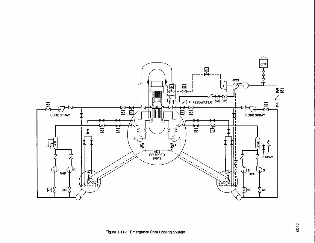
The purpose of the emergency core coolingsystems (ECCS) is to provide core cooling underloss of coolant accident (LOCA) conditions tolimit fuel cladding damage.
The ECCS, shown in Figure 1. 1 -1, consists oftwo high pressure systems and two low pressuresystems. The high pressure systems are the HighPressure Core Spray (HPCS) System and theAutomatic Depressurization System (ADS). Thelow pressure systems are the Low Pressure CoreSpray (LPCS) System and the low pressurecoolant injection (LPCI) mode of the ResidualHeat Removal (RHR) System.
1.11.1 High Pressure Core Spray System
The High Pressure Core Spray System maintainsreactor vessel water inventory after small loss ofcoolant accidents (LOCAs), provides spraycooling for larger LOCAs, and backs up thefunction of the Reactor Core Isolation Cooling(RCIC) System under reactor vessel isolationconditions
reactor pressure is low enough for the system toinject water into the reactor vessel.
1.11.4 Residual Heat Removal System
The low pressure coolant injection (LPCI) modeof the Residual Heat Removal (RHR) Systemrestores and maintains water level in the reactorvessel following LOCAs when reactor pressure islow enough for the system to inject water into thereactor vessel. The RHR System has several otheroperational modes, some of which are safetyrelated and some of which are not.
1.11.5 Commission Requirements
The Code of Federal Regulations requires theECCS to be designed so that following any LOCAthe reactor core remains in a geometricalconfiguration amenable to cooling. The basiccriteria are to limit fuel cladding temperature andoxidation to minimize clad fragmentation, and tominimize the hydrogen generation from cladoxidation to protect the containment.
1.11.2 Automatic Depressurization System
The Automatic Depressurization System (ADS)depressurizes the reactor vessel so that the lowpressure emergency core cooling systems caninject water into the reactor vessel following smallor intermediate sized LOCAs concurrent withHPCS System failure.
1.11.3 Low Pressure Core Spray System
The Low Pressure Core Spray (LPCS) Systemprovides spray cooling to the reactor core to helpmitigate the consequences of LOCAs when
USNRC Technical Training Center 1.11.1 Rev UIUIJUSNRC Technical Training Center 1.11-1 Rev U1WU
-4 w---- IHPCI
00
Figure 1.11-1 Emergency Core Cooling System
General Electric Technology Manual Reactor PhysicsGeneral Electric Technoloav Manual Reactor Physics
1.12 REACTOR PHYSICS
The purpose of this section to provide a basicunderstanding of certain reactor physics conceptsrelating to Boiling Water Reactor (BWR)technology. For a more detailed discussion of thissubject matter, additional reference materialshould be consulted.
1.12.1 Neutron Cycle
The principle of operating a nuclear reactor isbased on neutron economy. Many of theprocesses within the reactor compete for theneutrons. The designer's problem becomes howto ensure that, under design conditions, eachneutron in the previous generation produces onein the next generation.
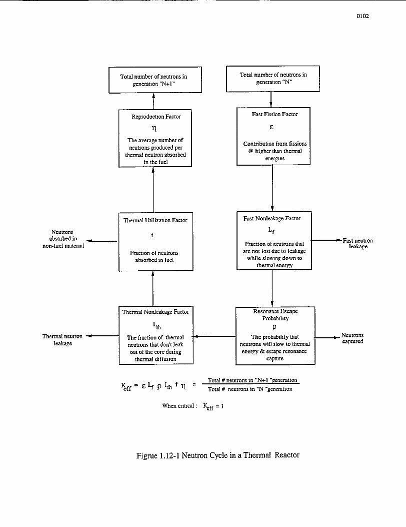
A BWR is a thermal reactor. The term "thermalreactor" infers that fission is produced by neutronsin thermal equilibrium with the reactor corematerial. In a thermal reactor, the neutronsproduced by thermal fission have very highenergies and are called fast neutrons. They slowto thermal energies by collisions with moderator(water) nuclei. Some are then absorbed byfissionable nuclei with the subsequent fissionsproducing a new generation of neutrons. Figure1.12-1 shows the neutron cycle for a thermalreactor and the process involved in slowing theneutrons down to thermal energies.
1.12.2 Effective Multiplication Factor
The ratio of neutrons in the new generation to thenumber in the previous generation is called theeffective multiplication factor, Keff. Keff may beexpressed as:
For a reactor to be critical the effectivemultiplication factor must be unity. Thus, there isa constant number of neutrons in each generationand the fission energy is released at a constantrate. When Keff is greater than unity the reactoris said to be supercritical and the power level willrise exponentially. Great care must be exercisedthat the rate of increase be kept within reasonablelimits. When Keff is less than 1, the reactor issubcritical and there will be a decrease in neutronpopulation and power.
1.12.3 Shutdown Margin
The shutdown margin is the amount by which thereactor is subcritical. Mathematically, this can beexpressed as:
SDM = 1 - Keff (for keff <1)
The design shutdown margin will be specified forthe plant, and tests will be conducted periodicallyto demonstrate that it is met. The value specifiednormally assumes that the strongest rod is stuck inthe fully withdrawn condition. These testsdemonstrate a margin of safety should that eventoccur.
1.12.4 Reactivity
Reactivity (symbol AK/K) can be defined as thefractional change in neutron population pergeneration. Mathematically this can be expressedas follows
Ak/k = (keff- 1)/keff
If a reactor is critical,AK/K = 0 and keff = 1. If areactor is subcritical, AK/K < 0 and keff <1. If areactor is supercritical, AK/K > 0 and keff >1.
keff = Neutrons producedNeutrons absorbed + neutron leakage
USSNRC Technical Training Center USNRC Technical Training Center 1.12.1 Rev 03001.12-1 Rev 0300
General Electric Technology Manual Reactor PhysicsGeneral Electric Technology Manual Reactor Physics
1.12.5 Reactivity Coefficients
The reactivity coefficients are merely a means ofdescribing the effect on the multiplication factor(Keff) due to changes in a particular reactorparameter. They are usually expressed in terms ofAK/K/unit of parameter variable. There are threesuch coefficients at work in a BWR operating atpower. These are the moderator temperaturecoefficient, the moderator void coefficient, andthe fuel temperature coefficient.
1.12.5.1 Moderator TemperatureCoefficient (aT)
The moderator temperature coefficient is definedas the change in reactivity caused by a 1°F changein moderator temperature. aT in a BWR isdesigned to be negative by establishing a propermoderator to fuel ratio. As the temperature of themoderator increases it becomes less dense. Thisdecreases the amount of neutron moderation andincreases the probability that a neutron willundergo nonfission absorption in a control rod orsome core structural material.
1.12.5.2 Moderator Void Coefficient (aV)
The moderator void coefficient is defined as thechange in reactivity caused by a one percentchange in void concentration in the core. aV isnegative because an increase in moderator voidscauses the leakage components of Keff to bedominant as with the moderator temperaturecoefficient.
1.12.5.3 Fuel Temperature Coefficient (aD)
The fuel temperature coefficient, also referred toas the doppler coefficient, is defined as the changein reactivity caused by a 1 F change in fueltemperature. The effect of aD is attributed to thefact that U238 and Pu240 have an affinity to
capture neutrons of certain energy levels, calledresonance peaks. Capturing the neutron is a formof neutron leakage since the neutron cannot causefission. As the fuel is heated, the resonanceabsorption of neutrons in U238 and Pu240increases, causing a decrease in core reactivity.Hence aD is also negative.
1.12.5.4 Reactivity Coefficient Values
Approximate numerical values for the threereactivity coefficients are as follows:
axV I X 10-3 AK/K /% voids
aT - 1 X 10⁻⁴ AK/K/0F moderator
aD -1 X 10⁻⁵ AK/K /F fuel
From these values it is easy to see that the voidcoefficient is dominant when the reactor is in thepower range (i.e. a substantial percentage ofvoids).
1.12.6 Reactor Control
When a reactor is operating at steady state, asdiscussed in section 1.12.2, the effectivemulitplication factor, Keff is unity; there is aconstant number of neutrons in each generationand the fission energy is released at a constantrate. To change the power level of the reactor, therate of fission energy released or the number ofneutrons in each generation must be changed.While the power is increasing or decreasing, Keffdiffers from unity. The operator must limit thechanges in Keff (reactivity) so that the reactor canbe controlled.
An expression for how reactor power will varywith time is
P = Poet/T
USNRC Technical Training Center 1.12-2 Rev 0300USNRC Technical Trainin- Center 1.12-2 Rev 0300
General Electric Technology Manual Reactor PhysicsGeneral Electric Technology Manual Reactor Physics
where P is the power of some time, t ; Po is thepower at time t = o; and T, the reactor period, isthe time for the power to change by a factor of thenatural log base (e).
For the reactor to be at steady state P = Po and,therefore T = o. Reactor period is a veryimportant concept and is one of the mostresponsive indicators of reactor conditions: Allreactors employ an automatic safety system whichwill rapidly shutdown (scram) the reactor if theperiod gets too short, avoiding dangerous powerexcursions.
The following sections apply the principlescovered above to explain reactor control during anormal startup from a cold shutdown condition.The response of the reactor can be broken downinto three distinctly different areas: the sourcerange, the intermediate range and the power range.Each of these areas will be covered below.
1.12.6.1 Source Range
The source range covers approximately 10-8%to 104% reactor power. Neutron flux is in thisrange when the reactor is shutdown and during theinitial phases of a reactor startup. When startingthe reactor, the power is controlled by control rodwithdrawal to establish the reactor in the criticalcondition.
Before withdrawing any control rods to begin thestartup, the operator verifies that there is aminimum count rate indicated on the source rangemonitor (Section 5.1). Source neutrons arepresent in the reactor so that it is possible to seethe approach to critical on the reactorinstrumentation. If there were no source neutronspresent, the instrument range would not besensitive enough to detect a positive, increasingperiod until the power was high enough toindicate on the instrumentation. By the time thepower was indicating on the instruments, the
period could be very short and a startup accidentcould occur.
As the operator withdraws control rods, anonfission absorber is removed from the corecausing Keff to increase and neutronmultiplication can be seen on the instrumentation.When enough control rods have been withdrawnto raise Keff to 1, the reactor is critical. Furthercontrol rod withdrawal then establishes a rate ofpower increase into the intermediate range tocommence a plant heat up.
1.12.6.2 Intermediate Range
The intermediate range encompasses power levelsfrom approximately 10-5% to about 40%. Thepower level is controlled by control rods and thenegative feedback effect of the moderatortemperature coefficient of reactivity.
Recall that the intermediate range is enteredslightly supercritical. To the unwary operator thiscan be a problem. A rapidly increasing flux levelcan give a high level flux scram from theintermediate range monitors (Section 5.2).Attention must be paid to proper range switching.When power increases to the point of adding heat,moderator temperature will increase. Asmoderator temperature increases, the density ofthe moderator decreases. The decrease inmoderator density adds negative reactivity to thecore which causes reactor power to turn and startto decrease. The operator now withdraws acontrol rod (or rods) until core reactivity ispositive and the process is repeated. The rate atwhich this is done and the magnitude of positivereactivity controls reactor power, which in turncontrols the heatup rate. This process is continueduntil the plant is at its operating temperature. Thepurpose of power control here is to control theheat up rate of the plant to prevent undue thermalstresses on plant structural materials.
USNRC Technical Training Center 1.12-3 Rev 0300USNRC Technical Training Center 1.12-3 Rev 0300
General Electric Technology Manual Reactor PhysicsGeneral Electric Technology Manual Reactor Physics
1.12.6.3 Power Range
For this discussion, the power range is consideredto be a power level greater than 1%. The reactorstill responds by the P = Poet/T expression in thepower range. However, this response is difficultto recognize because it is impossible to establisha stable period. There is always some factorresisting a power increase or decrease. Therefore,an attempt to establish a positive period by controlrod withdrawal is immediately terminated at somefractionally higher power because of increasedvoids, fuel temperature, or moderator temperature.Thus, the negative reactivity coefficients related tothe fuel temperature and core void fractionprovide a negative feedback to power changes.The effect of the moderator temperaturecoefficient ( aT) is limited here because of thepressure and temperature relationship atsaturation, and the constant pressure maintainedby the Electro-Hydraulic Control System.
From 1% to approximately 25%, reactor power iscontrolled to establish plant conditions requiredfor rolling the turbine and picking up initial loadon the generator. From 25% to 100%, reactorpower is controlled to control the generator load.Reactor control is accomplished through use ofcontrol rods and the recirculation system. Whenthe plant startup is complete, power rangeoperation is normally steady state. Small powerchanges required to accommodate grid loadchanges are normally done by adjustingrecirculation flow. Longer term reactivitychanges, caused by fission product poisons(hours) and fuel depletion (weeks), are offset bycontrol rod movement under the direction of thenuclear engineer.
1.12.7 Fission Product Effects
During the course of operation of a nuclearreactor, the fission fragments and their manydecay products accumulate. Among these
substances there are some, xenon-135 andsamarium-149 in particular, which have largeprobabilities (cross sections) for thermal neutronabsorption. These nuclei, therefore, act as reactorpoisons and effect the multiplication factor,chiefly by decreasing the thermal utilization.
The concentration of fission product poisons in areactor is related to the thermal-neutron flux (ordensity). Consequently, when power is changed,so that there is an accompanying change in theneutron density, the concentration of fissionproduct poisons will be affected and this will, inturn, influence reactivity. This effect must beconsidered in core design and control systemdesign.
Because of more rapid formation and removal,and higher absorption probabilities, xenonpresents a greater short term reactivity controlproblem than samarium.
1.12.7.1 Xenon
Xenon-135 can be formed both directly andindirectly in fission and can be removed byradioactive decay and by neutron capture. As aresult of the two opposing types of reactions, thecon- centration of xenon-135 will reach anequilibrium value while the reactor operates at aspecific power level.
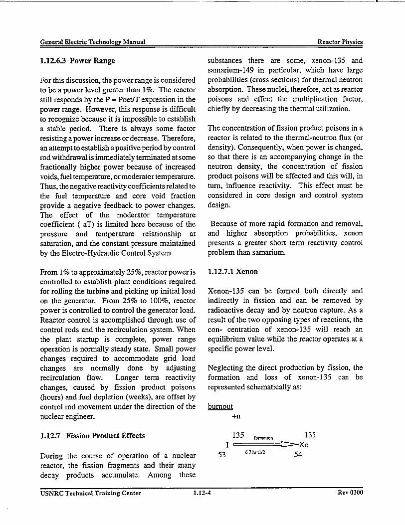
Neglecting the direct production by fission, theformation and loss of xenon-135 can berepresented schematically as:
burnout+n
135 fomatlon 135I XeCZ Xe
53 67hr/2 54
USNRC Technical Training Center 1.12-4 Rev 0300USNRC Technical Training Center 1 .12-4 Rev 0300
General Electric Technoloc-,v Manual Reactor PhysicsGeneral Electric Technolo�v Manual Reactor Physics
decay
9.2 hrtl/2
From this diagram, one can associate theformation term largely with prior operation(needed to produce iodine-135) and the burnoutterm +n with current power level (producesneutrons for capture by xenon-135). For example,after some hours of operation, if the reactor issuddenly shutdown, the burnout term is removedand the xenon simply cannot decay as fast (9.2 hrtf) as it is being formed from iodine (6.7 hr t"-)and for a while, the xenon concentration willincrease until most of the iodine has decayed andthe xenon decay dominates. Conversely, a suddenrise in power level equates to an increase inneutron flux (the burn-out term) and, for a while,the xenon depletes faster than it can be formedfrom decay of the iodine backlog created at thelower power level.
equilibrium concentration and its reactivity effectsfollowing power changes are several magnitudesless than xenon's. Samarium is often treated as anequilibrium poison and its transient effectsneglected.
Operationally, as xenon changes, other poisons inthe core (control material such as control rods)must be added or removed to maintain criticality.Whenever the power level is changed, theoperator must consider the effect xenon will haveon continued operation.
1.12.7.2 Samarium
Next to xenon-135, the most important fissionproduct poison is samarium-149. It is the endproduct of the decay chain
149 149 149Nd Pm c = Sm
60 1.7 hr t' 61 47 hr t' 62
Samarium- 149 is a stable nuclide, is removed onlyby burnout and has a probability for neutronabsorption about 100 times smaller than that ofxenon-135. Considering on operating BWR, ittakes several days for samarium to build up to an
USNRC Technical Training Center 1.12-5 Rev 0300USNRC Technical Training Center 1.12-5 Rev 0300
General Electric Tecbnologyv Manual Reactor PhysicsGeneral Electric Technolo�v Manual Reactor Physics
USNRC Technical Training Center 1.12-6 Rev 0300USNRC Technical Training Center 1 .12-6 Rev 0300
0102
I
Total number of neutrons ingeneration "N+l"
-
1 Total number of neutrons ingeneration "N"
1Reproduction Factor
The average number ofneutrons produced per
thermal neutron absorbedin the fuel
Fast Fission Factor
E
Contribution from fissions@ higher than thermal
energies
ieNeutrons
absorbed in -non-fuel material
Thermal neutron -
leakage
Thermal Utilization Factor
f
Fraction of neutronsabsorbed in fuel
Fast Nonleakage Factor
Lf
Fraction of neutrons thatare not lost due to leakage
while slowing down tothermal energy
---- Fast neutronleakage
_
L :Thermal Nonleakage Factor
Lth
The fraction of thermalneutrons that don't leakout of the core during
thermal diffusion
__I_Resonance Escape
Probability
pThe probability that
neutrons will slow to thermalenergy & escape resonance
capture
_- Neutronscaptured
Kff = £ Lf p lth f TiTotal # neutrons in "N+l "generation
Total # neutrons in "N "generation
When critical: Keff = I
Figrue 1.12-1 Neutron Cycle in a Thermal Reactor
General Electric Technoloev Manual ThermaI LimitsGeneral Electric Technolo�v Manual Thermal Limits
1.13 THERMAL LIMITS
The purpose of having thermal limits is tominimize the radiological release from the plantduring normal operation, abnormal operation,abnormal operational transients, and postulatedaccidents by restricting plant operation so that thefuel cladding integrity is maintained.
Fuel clad damage (loss of cladding integrity) isdefined, for design purposes, as a perforation ofthe cladding which permits release of fissionproducts. The mechanisims which could causefuel damage are:
* Rupture of the cladding due to strain causedby relative expansion of the uranium dioxidepellet and the fuel cladding.
* Severe overheating of the fuel cladding causedby inadequate cooling.
The basic thermal limits are shown in Figure 1.13-1.
1.13.2 Background Information
In order to understand the BWR thermal limits, itis necessary to have an understanding of relatedbackground material such as heat transfer andfluid flow characteristics. This subject material isdiscussed in the paragraphs that follow.
1.13.2.1 Heat Transfer
In light water reactor operation, heat is transferredfrom the fuel center line to the light watermoderator which comes into contact with theouter fuel cladding surface. The heat can betransferred by conduction, convection, orradiation. Conduction and convection are themodes of heat transfer of primary interest innuclear power plant operations.
1.13.1 Thermal Limit Description
Thermal limits are provided for normal operationand transient events to maintain the integrity ofthe fuel cladding. This objective is achieved bylimiting fuel rod power density to avoidoverstressing the fuel cladding because of fuelpellet- cladding differential expansion and bymaintaining nucleate boiling around the fuel rodsso that the transition to film boiling is avoided.The thermal limits established for these purposesare the linear heat generation rate (LHGR) limitand the minimum critical power ratio (MCPR)limit.
A thermal limit is provided for postulatedaccidents to maintain the core geometry byminimizing the gross fuel cladding failure becauseof the heatup following a loss of coolant accident(LOCA). The thermal limit established for thispurpose is the maximum average planar linearheat generation rate (MAPLHGR) limit.
1.13.2.1.1 Conduction
When heat is applied to a material, the kineticenergy of the atoms or molecules of the materialis increased. Because of this increase in kineticenergy, the particles have a greater tendency tocollide with each other. When these collisionsoccur, the particles transmit a portion of theirkinetic energy to neighboring atoms. This isconduction.
This is the process by which heat generated in thefuel pellet is transmitted to the outer clad surface.In relation to the fuel rod, this conduction flow isin a horizontal plane from the fuel center line tothe cladding surface.
1.13.2.1.2 Convection
Convection is the process of transmitting heatfrom a heated surface or area to a fluid by
USNRC Technical Training Center 1.13-1 Rev 01W)USNRC Technical Training Center 1.13-1 Rev 0100
General Electric Tachnolnqv Manual Thermal Limnits(eneral Flectrk Technn1n�v Manual Thermal Limits
circulation or mixing of the fluid. Convectiontakes place only in fluids.
The application in this case deals with a fluid(moderator) flowing past a metallic fuel claddingsurface. Fluids have a tendency to adhere to solidsurfaces resulting in the formation of a stagnantfilm on the surface. This film is normally verythin and heat is transferred across this film by acombination of conduction and convection. Afterthe heat penetrates the film, it is transferredrapidly through the remainder of the fluid bymixing.
The resistance of heat flow is so low that there isvirtually no temperature variation through thebulk of the fluid (moderator) at any givenelevation along the fuel rod.
1.13.2.1.3 Radiation
Radiation heat transfer is the transmission of heatin the form of radiant energy from one object toanother across an intervening space. This form ofheat transfer is avoided in nuclear power plantsbecause very high temperature differentials arerequired to transfer a significant amount of heat.These high temperatures would cause degradationof materials if allowed to occur.
1.13.3 Boiling Heat Transfer
The boiling heat transfer curve is shown in Figure1.13-2. The amount of heat transferred from thefuel cladding to the coolant is greatly affected bythe coolant properties and by the thermal andhydraulic conditions of the coolant. The rate atwhich heat is transferred from the cladding, theheat flux, is dependent on the specific temperaturedifference between the cladding and the coolant(DT) and the heat transfer coefficient. The heatflux may be plotted against the temperaturedifference between the cladding and the coolant.This curve can be divided into boiling regions
corresponding to the regions shown in Figure1.13-2. The heat transfer coefficient in eachregion is controlled by the mode of heat transferin that region.
The first region is single phase convection heattransfer. The heat flux increases somewhat withincreased DT.
The second region is associated with subcoolednucleate boiling. Subcooled nucleate boiling isboiling at the cladding surface with the bulkcoolant temperature not yet at saturationtemperature. The steam bubbles may collapsebefore departing from the cladding surface or theywill collapse as they enter the subcooled regionafter departing from the surface. This mode ofconvective heat transfer is a complicated mixtureof single phase convection and nucleate boilingmodes of heat transfer.
The next region is fully developed bulk nucleateboiling. Nucleate boiling is a very efficient modeof heat transfer because of high turbulence createdby the boiling process. Nucleate boiling ismaintained in the core in all modes of normaloperation and in all transient conditions caused bya single operator error or equipment malfunction.
The heat flux increases as the temperaturedifference between the cladding and the~ coolantincreases. There is a point, however, where theheat transfer coefficient no longer increases withan increased DT. There is a transition boilingregime where the boiling mode changes fromnucleate boiling to film boiling. This region ishighly unstable and is characterized by theintermittent physical rewetting of the heatedsurface by the coolant. The beginning of thisregion is called onset of transition boiling (OTB)and is labeled so on Figure 1.13-2. The OTBpoint is avoided in the BWR by remaining withinthe critical power ratio thermal limit.
USNRC Technical Training Center 1.13-2 Rev U1UUUSNRC Technical Training Center 1.13-2 Rev 0100
N~n~al Fltrr Teehn~nCnV Mansni Thermal Limits-t1s 41 DSWSX sOs-; s
The crosshatched region represents temperatureoscillations which take place during transitionboiling. At a given heat flux the clad surfacetemperature will oscillate between a point on theright in the crosshatched region and a point on theleft in the crosshatched region along a horizontalline. This is caused by intermittent physicalrewetting of the clad surface. At the point of onsetof transition boiling (OTB), the temperatureoscillations reach 250F in magnitude; this isdefined as the critical power.
1.13.3.1 Fluid Flow
Figure 1.13-3 shows the different flow patternswhich can exist in a fuel bundle during normaloperation. As coolant (single phase liquid) entersthe fuel bundle it is slightly subcooled, andbegins to gain heat from the forced flowconvection mechanism. Because of subcooling,there is little or no bubble formation. As energyis gained, the coolant temperature increases untilnucleate boiling with its attendant bubbleformation begins Early states of nucleate boilingoccur while the bulk coolant in the bundle isbelow liquid saturation enthalpy, and the bubblesreadily collapse as the turbulent flow and theirbuoyancy sweeps them away from the cladsurface. A point will be reached where the bulkcoolant enthalpy is at liquid saturation, (bulkboiling) and the bubbles will no longer collapse inthe coolant as they are swept away. The bubblesnow begin to exist separately throughout the bulkcoolant, causing a significant steam fraction to bepresent in the coolant. From this point to thebundle outlet, the bubbles continue to form at thefuel rod surface (nucleate boiling) and be sweptinto the coolant and begin to coalesce into largerand larger slugs of steam (slug flow). At theoutlet of very highest powered fuel bundles, steammay fill most of the bundle flow area between fuelrods, but a thin annulus of water adheres to thefuel rod surfaces (annular flow). In this annularflow region, the wetted rod surface is still
transferring heat through the nucleate boilingmechanism.
1.133.1.1 Fuel Channel ParameterCharacteristics
Figure 1.134 shows a plot of coolant and fuelbundle temperature versus flow path length of anaverage fuel bundle. Coolant enters the bottom ofthe core, flows upward around the fuel rods, andabsorbs energy from heat transfer originating fromthe nuclear process. Because of the peculiarcharacteristics of neutron caused fission reactions,the average heat flux (Q/A) produced from fissionin the core assumes a shape somewhat like thatshown in Figure 1.134. The highest heat flux isin the core interior, hence some fuel bundles havea higher than average heat flux while some havelower than average.
The coolant temperature curve rises as heat isadded, until temperature saturation occurs, andcoolant bulk boiling begins. From this point thecoolant temperature remains constant all the wayto the core outlet. Because the coolant ischanging phase, the coolant temperature profile isnot altogether descriptive of coolant energyincrease. A better description is obtained byplotting coolant enthalpy change, whichcontinuously increases from core inlet to outlet,with the largest rate of increase at the maximumvalue of heat flux.
The curve for fuel rod surface temperature risesand then levels at a constant value above coolanttemperature. The initial rise is caused by the DTacross the film required to accommodate the heatflux (Q/A) during single phase forced convectionheat transfer. The point where the fuel rodtemperature levels off is because of the start ofnucleate boiling. Nucleate boiling is an excellentheat transfer mode; therefore, even though theheat flux increases, the DT across the boiling filmremains relatively constant.
USNRC Technical Training Center 1.13-3 k(�V uiuuUSNRC Technical Training Center 1.13-3 Rev U10V
General Electric Technology Manual ThernIa LimitsGeneral Electric Technolo2v Manual Therm�I Timitq
The curve for fuel rod center line temperature isabove that of the fuel surface temperature. Theamount that the center line temperature is greaterthan surface temperature depends directly on theheat flux. The beneficial effects of nucleateboiling on center line temperature can also beseen. As long as nucleate boiling is occurring onthe fuel rod surface, the fuel rod surfacetemperature is only slightly greater than liquidtemperature. This, in turn, keeps the fuel centerline temperature at a lower value than if singlephase convection were the mode of heat transferfrom surface to liquid
1.13.3.1.2 Fuel Temperature Profile
Figure 1.13-5 graphically illustrates a typical fueltemperature cross section with nucleate boiling ata high heat flux and its benefits. As long asnucleate boiling is occurring on the fuel rodsurface, the fuel rod surface temperature is onlyslightly greater than liquid temperature. This, inturn, keeps the fuel center line temperature at alower value than if single phase convection werethe mode of heat transfer from surface to liquid.
1.13.4 The LHGR Limit
Linear heat generation rate (LHGR) is the surfaceheat flux integrated over each square centimeter ofcladding material in one linear foot of a fuel rod.Limits on LHGR are set to limit the strain on thefuel clad because of relative expansion of the fuelpellets and the clad. A value of 1 percent plasticstrain of the cladding is conservatively defined asa threshold below which fuel damage due to fuelclad overstraining is not expected to occur.
Limits on LHGR are set to limit the strain on thefuel clad because of relative expansion of U02 andthe clad. Relative expansion arises from severalsources: the U0 2 fuel thermal expansioncoefficient is approximately twice that of zircaloy;the fuel pellets operate at higher temperatures than
the clad; the fuel pellets undergo irradiationgrowth as they are exposed; and the fuel pelletscrack and redistribute toward the clad due tothermal stress. Cladding cracking because ofdifferential expansion of pellet and clad isprevented by limiting fuel pin power such that 1%plastic strain does not occur.
The linear heat generation rate required to cause 1percent cladding strain in 8x8 fuel isapproximately 25 kW/ft for unirradiated fuel, butdecreases with bumup to a value of approximately20 kW/ft at a local exposure of 40,000 Mwd/MT.
The design LHGR for 8x8 fuel is 13.4 kW/ft,which provides a margin to the 1% plastic strainthreshold. The maximum LHGR in the core ismonitored by calculating peaking factors.
1.13.5 The APLHGR Limit
Average planar linear heat generation rate(APLHGR) is the average LHGR of all fuel rodsin a given fuel bundle in a given horizontal plane(actually a 6 inch slab or node). This parameter isimportant in the core heatup analysis for a loss ofcoolant accident (LOCA).
In the event of a LOCA, the heat stored in the fuelat the time of the accident and the decay heatproduced following the accident couldsignificantly damage the fuel. In the case of someLOCA's, nucleate boiling is maintained aroundthe fuel long enough for the majority of the storedenergy in the fuel to be conducted to the coolant;thus fuel damage is minimized. In the designbasis LOCA, however, the core region is voidedof liquid coolant in a relatively short time. If thefuel is operating at a high enough power level, thestored energy in the fuel could lead to a grosscladding failure and possible severe degradationof core geometry. Once water is removed fromthe cladding, radiation is the only heat transfermechanism.
USNRC Technical Training Center 1.13-4 Rev 0100USNRC Technical Training Center 1.13=4 Rev 0100
General Electric Technoloev Manual Thermal LimitsGeneral Electric Technolocv Manual Thermal Limits
Gross cladding failure is prevented by placing alimit on the power level which would result in apeak cladding temperature (PCT) of 2200'Ffollowing a LOCA. The thermal limit specified isthe APLHGR which is used because the PCTfollowing a postulated LOCA is primarily afunction of the average heat generation rate of allthe rods of a fuel assembly at any axial locationand is dependent only secondarily on the rod-to-rod power distribution within an assembly. Thepeak clad temperature is calculated assuming aLHGR for the highest powered rod less than orequal to the design LHGR corrected for fueldensification.
The thermal limit in this case is given in terms ofthe incore maximum APLHGR (the MAPLHGR)and is specified for each individual fuel type as afunction of fuel exposure. The units of theMAPLHGR are the same as those of the LHGR(kW/ft) even though the parameters are different.
1.13.6 The CPR Safety Limit
detailed statistical analysis of uncertainties inmonitoring the core operating state and in theboiling transition correlation.
1.13.7 Summary
In summary, there are three basic thermal limits;linear heat generation rate (LHGR) and minimumcritical power ratio (MCPR) are limited to ensurefuel clad integrity during normal and transientoperation, maximum average planar linear heatgeneration rate (MAPLHGR) is limited to meetECCS criteria. LHGR limits are imposed toprevent fuel cladding perforation because ofmechanical stress of the fuel pellets. MCPRlimits are imposed to prevent cladding perforationbecause of the onset of transition boiling(breakdown of the heat transfer mechanism), andare modified to account for transients and flowconditions less than rated. MAPLHGR limits areimposed to restrict the amount of stored energy inthe fuel thus limiting the rate of cladding heatupon a LOCA.
Critical power is the fuel bundle power required tocause transition boiling somewhere in the fuelbundle. The critical power ratio (CPR) of a fuelbundle is the ratio of its critical power to theactual fuel bundle operating power. The CPR isa measure of how close to transition boiling a fuelbundle is operating. The minimum value of theCPR for all fuel bundles in the core is theminimum critical power ratio (MCPR) andrepresents the fuel bundle which is the closest totransition boiling. MCPR limits are imposed toavoid fuel damage due to severe overheating ofthe clad.
The MCPR safety limit is set at 1.07 to ensure thatin the event of an abnormal operating transient,more than 99.9% of the fuel rods in the core areexpected to avoid transition boiling. The marginbetween a MCPR of 1.0 (onset of transitionboiling) and the safety limit is derived from a
USNRC Technical Training Center 1.13-5 Rev 01W)USNRC Technical Training Center 1.13-5 Rev 0100
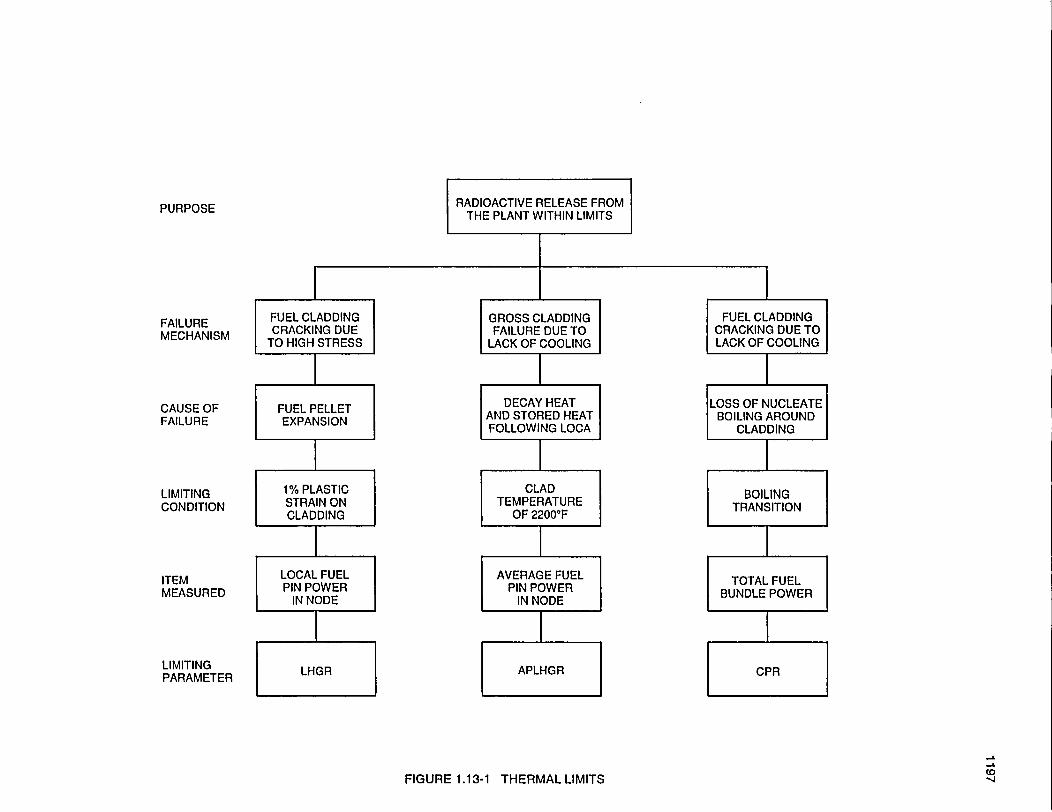
PURPOSE
FAILUREMECHANISM
CAUSE OFFAILURE
LIMITINGCONDITION
RADIOACTIVE RELEASE FROMTHE PLANT WITHIN LIMITS
FUEL CLADDINGCRACKING DUE
TO HIGH STRESS
I
GROSS CLADDINGFAILURE DUE TO
LACK OF COOLING
IFUEL CLADDING
CRACKING DUE TOLACK OF COOLING
IFUEL PELLETEXPANSION
1% PLASTICSTRAIN ONCLADDING
DECAY HEATAND STORED HEATFOLLOWING LOCA
LOSS OF NUCLEATEBOILING AROUND
CLADDING
I
CLADTEMPERATURE
OF 2200F
IAVERAGE FUEL
PIN POWERIN NODE
BOILINGTRANSITION
lITEMMEASURED
LIMITINGPARAMETER
LOCAL FUELPIN POWER
IN NODETOTAL FUEL
BUNDLE POWER
LHGR APLHGR CPR
-o
(D-4FIGURE 1.13-1 THERMAL LIMITS
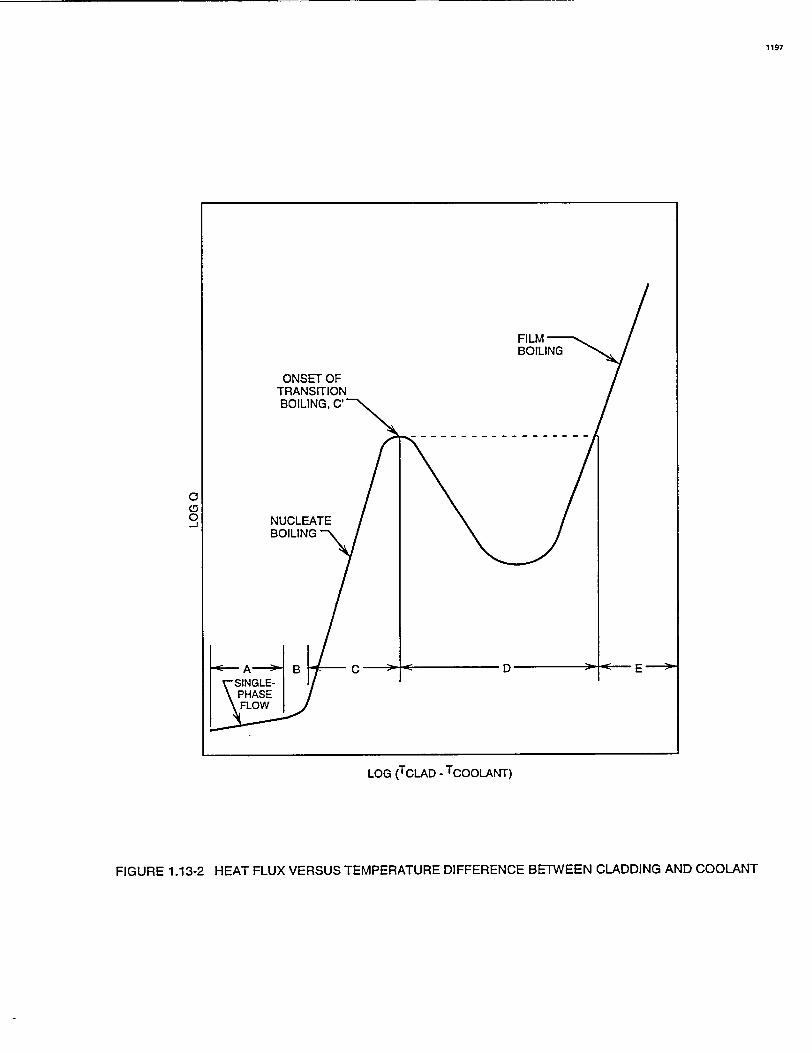
1197
LOG (TCLAD - TCOOLANT)
FIGURE 1.13-2 HEAT FLUX VERSUS TEMPERATURE DIFFERENCE BETWEEN CLADDING AND COOLANT
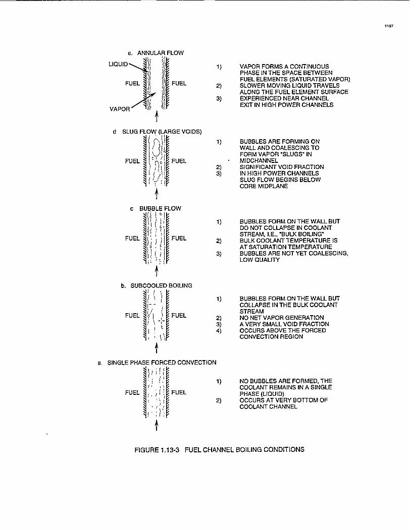
1197
e. ANNULAR FLOW
LIQUID FlL
FUEL FUEL
VAPOR/
d SLUG FLOW (LARGE VOIDS)
I FUELFUEL C lFE
IFUEL
1) VAPOR FORMS A CONTINUOUSPHASE IN THE SPACE BETWEENFUEL ELEMENTS (SATURATED VAPOR)
2) SLOWER MOVING LIQUID TRAVELSALONG THE FUEL ELEMENT SURFACE
3) EXPERIENCED NEAR CHANNELEXIT IN HIGH POWER CHANNELS
1) BUBBLES ARE FORMING ONWALL AND COALESCING TOFORM VAPOR 'SLUGS' INMIDCHANNEL
2) SIGNIFICANT VOID FRACTION3) IN HIGH POWER CHANNELS
SLUG FLOW BEGINS BELOWCORE MIDPLANE
1) BUBBLES FORM ON THE WALL BUTDO NOT COLLAPSE IN COOLANTSTREAM, I.E., 'BULK BOILING'
a) BULK COOLANT TEMPERATURE ISAT SATURATION TEMPERATURE
3) BUBBLES ARE NOT YET COALESCING,LOW QUALITY
1) BUBBLES FORM ON THE WALL BUTCOLLAPSE IN THE BULK COOLANTSTREAM
2) NO NET VAPOR GENERATION3) A VERY SMALL VOID FRACTION
OCCURS ABOVE THE FORCEDCONVECTION REGION
1) NO BUBBLES ARE FORMED, THECOOLANT REMAINS IN A SINGLEPHASE (LIQUID)OCCURS AT VERY BOTTOM OFCOOLANT CHANNEL
Ib. SUBCOOLED BOILING
FUEL I ]FUEL
a. SINGLE PHASE FORCED CONVECTION
FUEL FUEL
FIGURE 1.13-3 FUEL CHANNEL BOILING CONDITIONS
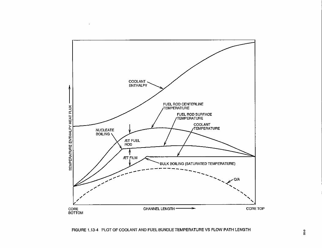
I EENTHALPY
x FEL ROD CENTERLINEx oTEMPERATURE
IL. FUEL ROD SURFACE
2 / /TEMPERATUREI g /COOLANT
>I TEMPERATURE-i NUCLEATE
< BOILING UL//
2 / /)ET FILM
IL:r/ m BULK BOILING (SATURATED TEMPERATURE)
/ /A
000
CORE CHANNEL LENGTH- CORE TOPBOTTOM
FIGURE 1.13-4 PLOT OF COOLANT AND FUEL BUNDLE TEMPERATURE VS FLOW PATH LENGTH 9
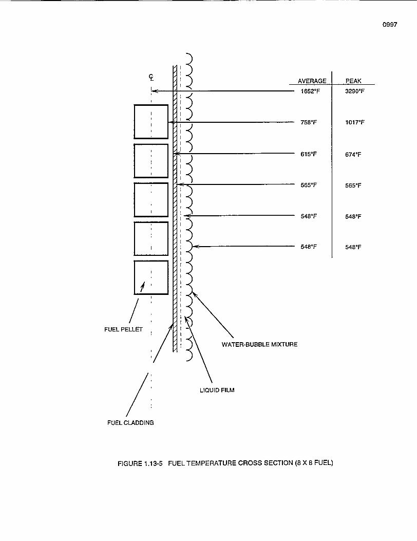
0997
AVERAGE PEAK_ _ _ _______ _,___. .
16520F
7580F
6150F
5650F
5480F
548°F
32900F
1017'F
6740F
5650F
5480F
5480F
FUEL PELLET
WATER-BUBBLE MIXTURE
LIQUID FILM
FUEL CLADDING
FIGURE 1.13-5 FUEL TEMPERATURE CROSS SECTION (8 X 8 FUEL)
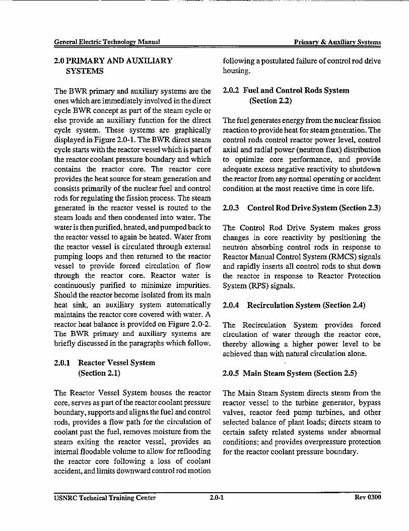
General Electric Technology Manual Primarv & Aux~iliarv SvstemsGeneral Electric Technoloev Manual Primary & Auxiliary Systems
2.0 PRIMARY AND AUXILIARYSYSTEMS
The BWR primary and auxiliary systems are theones which are immediately involved in the directcycle BWR concept as part of the steam cycle orelse provide an auxiliary function for the directcycle system. These systems are graphicallydisplayed in Figure 2.0-1. The BWR direct steamcycle starts with the reactor vessel which is part ofthe reactor coolant pressure boundary and whichcontains the reactor core. The reactor coreprovides the heat source for steam generation andconsists primarily of the nuclear fuel and controlrods for regulating the fission process. The steamgenerated in the reactor vessel is routed to thesteam loads and then condensed into water. Thewater is then purified, heated, and pumped back tothe reactor vessel to again be heated. Water fromthe reactor vessel is circulated through externalpumping loops and then returned to the reactorvessel to provide forced circulation of flowthrough the reactor core. Reactor water iscontinuously purified to minimize impurities.Should the reactor become isolated from its mainheat sink, an auxiliary system automaticallymaintains the reactor core covered with water. Areactor heat balance is provided on Figure 2.0-2.The BWR primary and auxiliary systems arebriefly discussed in the paragraphs which follow.
2.0.1 Reactor Vessel System(Section 2.1)
The Reactor Vessel System houses the reactorcore, serves as part of the reactor coolant pressureboundary, supports and aligns the fuel and controlrods, provides a flow path for the circulation ofcoolant past the fuel, removes moisture from thesteam exiting the reactor vessel, provides aninternal floodable volume to allow for refloodingthe reactor core following a loss of coolantaccident, and limits downward control rod motion
following a postulated failure of control rod drivehousing.
2.0.2 Fuel and Control Rods System(Section 2.2)
The fuel generates energy from the nuclear fissionreaction to provide heat for steam generation. Thecontrol rods control reactor power level, controlaxial and radial power (neutron flux) distributionto optimize core performance, and provideadequate excess negative reactivity to shutdownthe reactor from any normal operating or accidentcondition at the most reactive time in core life.
2.0.3 Control Rod Drive System (Section 2.3)
The Control Rod Drive System makes grosschanges in core reactivity by positioning theneutron absorbing control rods in response toReactor Manual Control System (RMCS) signalsand rapidly inserts all control rods to shut downthe reactor in response to Reactor ProtectionSystem (RPS) signals.
2.0.4 Recirculation System (Section 2.4)
The Recirculation System provides forcedcirculation of water through the reactor core,thereby allowing a higher power level to beachieved than with natural circulation alone.
2.0.5 Main Steam System (Section 2.5)
The Main Steam System directs steam from thereactor vessel to the turbine generator, bypassvalves, reactor feed pump turbines, and otherselected balance of plant loads; directs steam tocertain safety related systems under abnormalconditions; and provides overpressure protectionfor the reactor coolant pressure boundary.
USNRC Technical Training Center 2.0-1 Rev 0300USNRC Technical Training Center 2.0-1 Rev 0300
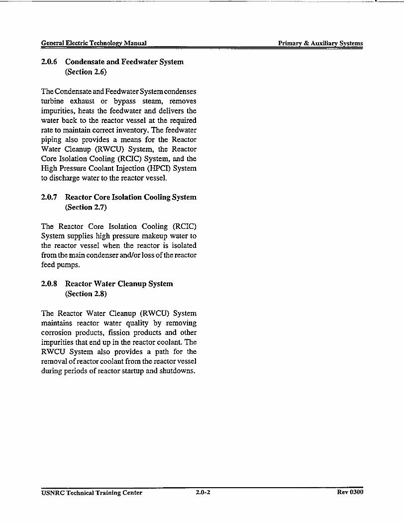
General Electric Technology Manual Primary & Auxiliary SystemsGeneral Electric Technology Manual Primary & Auxiliary Systems
2.0.6 Condensate and Feedwater System(Section 2.6)
The Condensate and Feedwater System condensesturbine exhaust or bypass steam, removesimpurities, heats the feedwater and delivers thewater back to the reactor vessel at the requiredrate to maintain correct inventory. The feedwaterpiping also provides a means for the ReactorWater Cleanup (RWCU) System, the ReactorCore Isolation Cooling (RCIC) System, and theHigh Pressure Coolant Injection (HPCI) Systemto discharge water to the reactor vessel.
2.0.7 Reactor Core Isolation Cooling System(Section 2.7)
The Reactor Core Isolation Cooling (RCIC)System supplies high pressure makeup water tothe reactor vessel when the reactor is isolatedfrom the main condenser and/or loss of the reactorfeed pumps.
2.0.8 Reactor Water Cleanup System(Section 2.8)
The Reactor Water Cleanup (RWCU) Systemmaintains reactor water quality by removingcorrosion products, fission products and otherimpurities that end up in the reactor coolant. TheRWCU System also provides a path for theremoval of reactor coolant from the reactor vesselduring periods of reactor startup and shutdowns.
USNRC Technical Training Center 2.0-2 Rev 0300USNRC Technical Training Center 2.0-2 Rev 0300
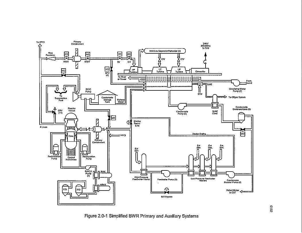
To HPCI PrimaryA Containment 24KV
880 MWeto Grid
StartupRecircLine
4 Lines
ExtStm
Pump
Low Pressure FeedwaterHeaters
S/U Bypass
0
0i
Figure 2.0-1 Simplified BWR Primary and Auxiliary Systems
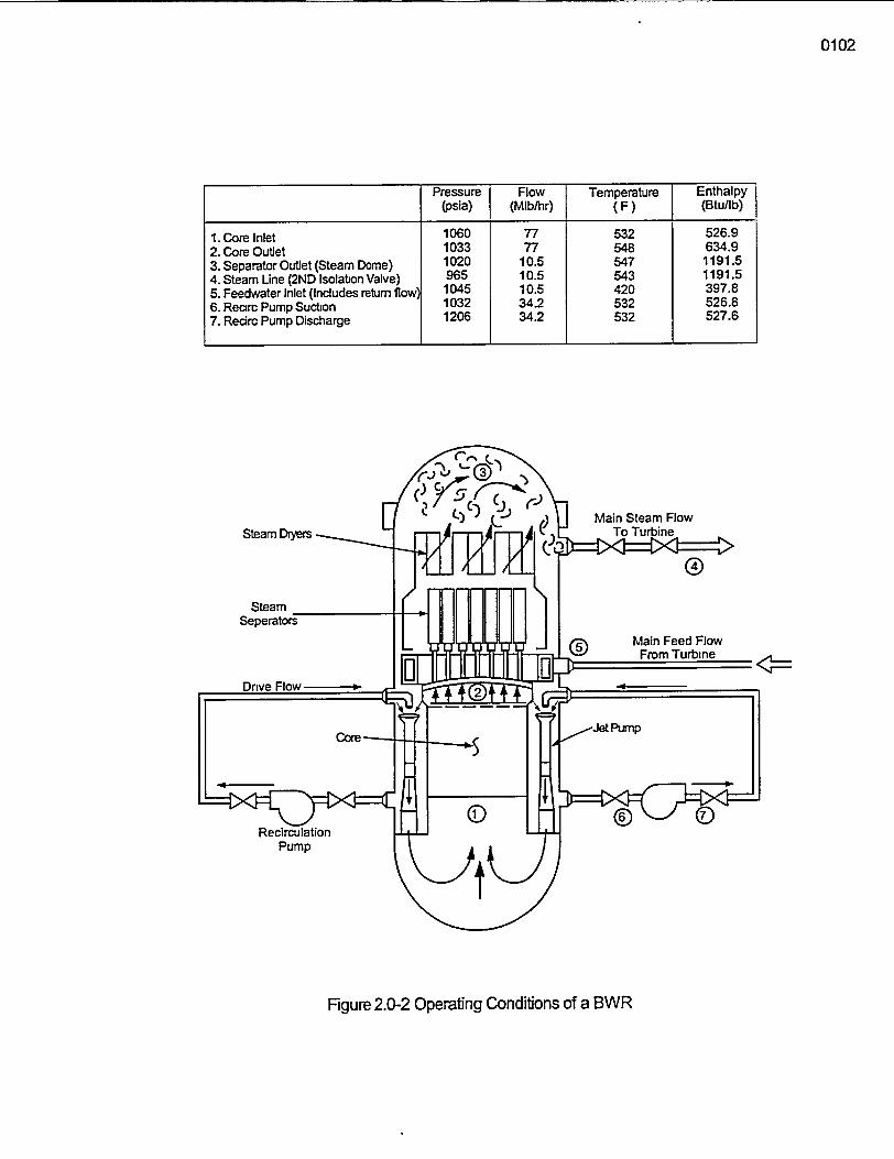
0102
Pressure Flow Temperature Enthalpy(psia) (Mlblhr) (F) (Btu/lb)
1. Core Inlet 1060 77 532 526.92. Core Outlet 1033 77 548 634.93. Separator Outlet (Steam Dome) 1020 10.5 547 1191.54. Steam Line (2ND Isolabon Valve) 965 10.5 543 1191.55. Feedwater Inlet (Indudes return flow) 1045 10.5 420 397.86. Rearc Pump Suction 1032 34.2 532 526.87. Recirc Pump Discharge 1206 34.2 532 527.6
Figure 2.0-2 Operating Conditions of a BWR
General Electric Technology Manual - Reactor Vessel System
Table -of Contents
2.1 REACTOR VESSEL SYSTEM ..... 12.1.1 System Description ........ ........ .' . -. ................ 1........... I2.1.2 Component Description ...........-...... ;................... 1
2.1.2.1 Reactor Vessel ............. .. :............ ............ 12.1.2.2 Annulus Region Components ......... ...;.-. .. 2
2.1.2.2.1 Feedwater Spargers ................................ 2
2.1.2.2.2 Recirculation Suction Penetrations ............................. 2
2.1.2.2.3 Recirculation Discharge Penetrations ........................... 2
2.1.2.2.4 Jet Pump Assemblies ......................................... 2
2.1.2.2.5 Baffle Plate ............................ . 22.1.2.3 Lower Plenum Region .... 3
2.1.2.3.1 Bottom Head Penetrations ............................. 3
2.1.2.4 Core Shroud Region Components ......................... . ... 42.1.2.4.1 Core Shroud ................................................ 4
2.1.2.4.2 Core Plate ........................................ 4
2.1.2.4.3 Top Guide ... 42.1.2.4.4 Fuel Support Pieces ................................... 4
2.1.2.4.5 Core Spray Spargers ..................................... 5
2.1.2.4.6 Shroud Head ... ............ 52.1.2.5 Moisture Separation Assemblies ........................... . ... 5
2.1.2.5.1 Steam Separator Assembly ..................... ...... 52.1.2.5.2 Steam Dryer Assembly ................................ 5
2.1.2.6 Main Steam Outlet Penetrations .................... . ........... 62.1.2.7 Vessel Head Penetrations .............................. . ....... 6
2.1.2.8 Vessel External Components .......................... . ... 62.1.2.8.1 Reactor Vessel Support Skirt ........ 62.1.2.8.2 Reactor Vessel Pedestal .............................. 62.1.2.8.3 Biological Shield ................................... 62.1.2.8.4 Reactor Vessel Insulation ............................. 6
2.1.2.8.5 CRD Housing Support Structure ....................... 72.1.3 System Features and Interrelations .................................. 7
2.1.3.1 Normal Operation (Figure 2.1-11) ......................... . ... 72.1.3.2 Core Floodability (Figure 2.1-12) .......... . .. 72.1.3.3 System Interrelations ............................... . ...... 8
2.1.3.3.1 Fuel and Control Rods System(Section 2.2) ................... 82.1.3.3.2 Control Rod Drive System (Section 2.3) ............ 82.1.3.3.3 Recirculation System (Section 2.4) .. 8
USNRC Technical Training Center 2.1 i - _ r .- - I Rev 0300
General Electric Technology Manual Reactor Vessel SystemGeneral Electric TechnoIo2y Manual Reactor Vessel System
Table of Contents (cont.)
2.1.3.3.42.1.3.3.52.1.3.3.62.1.3.3.72.1.3.3.82.1.3.3.9
2.1.4 Summary
Main Steam System (Section 2.5) ...............................Condensate and Feedwater System (Section 2.6) ....................Reactor Water Cleanup System (Section 2.8) .......................Reactor Vessel Instrumentation System (Section 3.1) ................Neutron Monitoring System (Section 5.0) .........................Core Spray (CS) System (Section 10.3) ...........................
.............................................................
8888889
List of Figures
Figure 2.1-1 ....... Reactor VesselFigure 2.1-2 .. . . . . . Typical Feedwater NozzleFigure 2.1-3 ....... Jet Pump AssemblyFigure 2.1-4 ....... Differential Pressrue, SLC Line & Shroud SupportFigure 2.1-5 ....... Shroud InternalsFigure 2.1-6 ....... Control Rod Guide Tube Housing AttachmentFigure 2.1-7 ....... Fuel Support PiecesFigure 2.1-8 .. . . . . . Core Spray Piping in VesselFigure 2.1-9 ....... Shroud Head and Steam SeparatorFigure 2.1-11 ........ Reactor Vessel InsulationFigure 2.1-12 .. . . . . . Reactor Vessel Flow PathsFigure 2.1-12 ....... Core Flooding Capability of Recirculation System
USNRC Technical Training Center 2.1-li Rev 0300USNRC Technical Training Center 2.1-ii Rev 0300
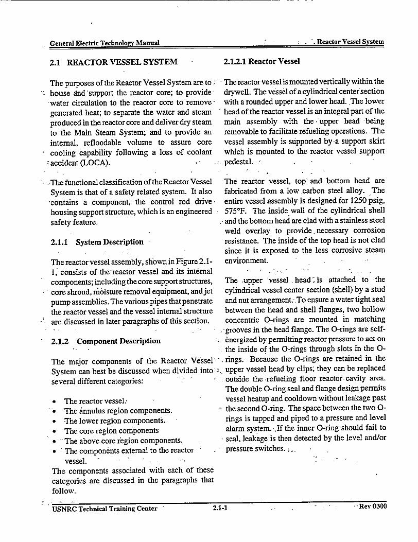
Toe-lk"MAOX, Un"Iml Reactor Vessel System
2.1 REACTOR VESSEL SYSTEM
The purposes of the Reactor Vessel System are to;house And'support the reactor core; to provide
-water circulation to the reactor core to remove,generated heat; to separate the water and steamproduced in the reactor core and deliver dry steamto the Main Steam System; and to provide aninternal, refloodable volume to assure corecooling capability following a loss of coolant
2.1.2.1 Reactor Vessel
- The reactor vessel is mounted vertically within thedrywell. The vessel of a cylindrical center sectionwith a rounded upper and lower head. The lowerhead of the reactor vessel is an integral part of themain assembly with the .'upper head -beingremovable to facilitate refueling operations. Thevessel assembly is supported by-a support skirtwhich is mounted to the reactor vessel support
* accident (LOCA). , - 1 - pedestal. -
-The functional classification of the Reactor VesselSystem is that of a safety related system. It also,contains a component, the control rod drive,housing support structure, which is an engineeredsafety feature.
2.1.1 System Description
The reactor vessel assembly, shown in Figure 2. 1-
-The reactor vessel, top- and bottom head arefabricated from a low carbon steel alloy. Theentire vessel assembly is designed for 1250 psig,575°F. The inside wall of the cylindrical shell
.- and the bottom head are clad with a stainless steel
weld overlay to provide necessary corrosionresistance. The inside of the top head is not cladsince it is exposed to the less corrosive steamenvironment.
1, consists of the-reactor vessel and its internal - .components; including the core support structures, The supper 'vessel -head; is attached to -the
core shroud, moisture removal equipment, and jet cylindrical vessel center section (shell) by a stud
pump assemblies. The various pipes that penetrate and nut arrangement.- To ensure a water tight seal
the reactor vessel and the vessel internal structure between the head and shell flanges, two hollow
are discussed in later paragraphs of this section. concentric 0-rings are mounted in matching- .- - grooves in the head flange. The 0-rings are self-
2.1.2 Component Description energized by permitting reactor pressure to act on^ - . the inside of the 0-rings through slots in the 0-
The major components of the Reactor Vessel - . rings.- Because the 0-rings are retained in the
System can best be discussed when divided into,' upper vessel head by clips; they can be replaced
several different categories: ' . outside the refueling floor reactor-cavity area.The double 0-ring seal and flange design permits
* The reactor vessel., vessel heatup and cooldown without leakage past
-The annulus region components. the second 0-ring. The space between the two 0-
* -The lower region components. - rings is tapped and piped to a pressure and level
* The core region components alarm system.-,If the inner 0-ring should fail to
* - The above core region components. seal, leakage is then detected by the level and/or
* The components external to the reactor - pressure switches. -
vessel. a * -
The components associated with each of thesecategories are discussed in the paragraphs thatfollow.
USNRC~ Tehia Trnn Cete .2.. m__. uauUSNRC Technical Training Center ' 2.1-1 II -I - Rev 0300
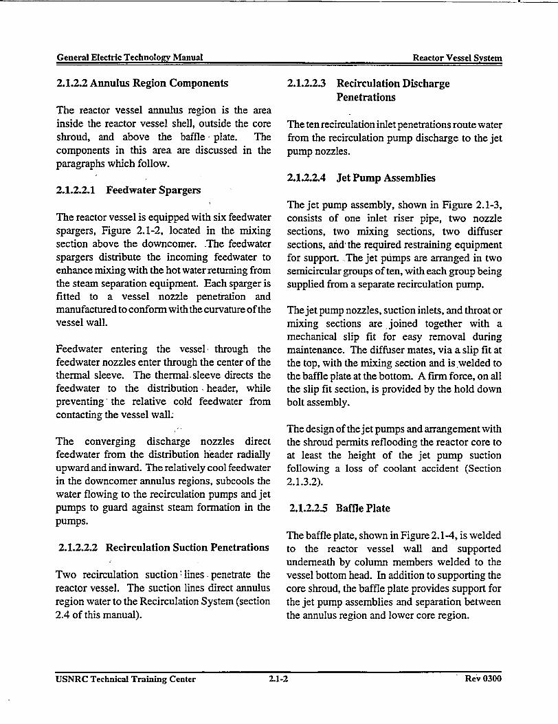
General Electric Technoloev Manual Reactor Vessel SvstemGeneral Electric Technolo2v Manual Reactor Vessel System
2.1.2.2 Annulus Region Components
The reactor vessel annulus region is the areainside the reactor vessel shell, outside the coreshroud, and above the baffle plate. Thecomponents in this area are discussed in theparagraphs which follow.
2.1.2.2.1 Feedwater Spargers
The reactor vessel is equipped with six feedwaterspargers, Figure 2.1-2, located in the mixingsection above the downcomer. The feedwaterspargers distribute the incoming feedwater toenhance mixing with the hot water returning fromthe steam separation equipment. Each sparger isfitted to a vessel nozzle penetration andmanufactured to conform with the curvature of thevessel wall.
Feedwater entering the vessel through thefeedwater nozzles enter through the center of thethermal sleeve. The thermal- sleeve directs thefeedwater to the distribution * header, whilepreventing- the relative cold feedwater fromcontacting the vessel wall.
The converging discharge nozzles directfeedwater from the distribution header radiallyupward and inward. The relatively cool feedwaterin the downcomer annulus regions, subcools thewater flowing to the recirculation pumps and jetpumps to guard against steam formation in thepumps.
2.1.2.2.2 Recirculation Suction Penetrations
Two recirculation suction lines -penetrate thereactor vessel. The suction lines direct annulusregion water to the Recirculation System (section2.4 of this manual).
2.1.2.2.3 Recirculation DischargePenetrations
The ten recirculation inlet penetrations route waterfrom the recirculation pump discharge to the jetpump nozzles.
2.1.2.2.4 Jet Pump Assemblies
The jet pump assembly, shown in Figure 2.1-3,consists of one inlet riser pipe, two nozzlesections, two mixing sections, two diffusersections, afid, the required restraining equipmentfor support. The jet pumps are arranged in twosemicircular groups of ten, with each group beingsupplied from a separate recirculation pump.
The jet pump nozzles, suction inlets, and throat ormixing sections are, joined together with amechanical slip fit for easy removal duringmaintenance. The diffuser mates, via a slip fit atthe top, with the mixing section and is welded tothe baffle plate at the bottom. A firm force, on allthe slip fit section, is provided by the hold downbolt assembly.
The design of the jet pumps and arrangement withthe shroud permits reflooding the reactor core toat least the height of the jet pump suctionfollowing a loss of coolant accident (Section2.1.3.2).
2.1.2.2.5 Baffle Plate
The baffle plate, shown in Figure 2.1-4, is weldedto the reactor vessel wall and supportedunderneath by column members welded to thevessel bottom head. In addition to supporting thecore shroud, the baffle plate provides support forthe jet pump assemblies and separation betweenthe annulus region and lower core region.
USNRC Technical Training Center 2.1-2 Rev 0300USNRC Technical Training Center 2.1-2 -Re-v 0300
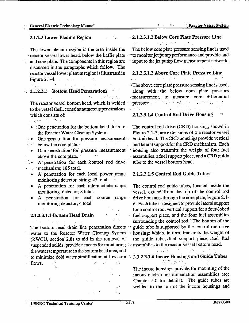
. , General Electric Technolopv Manual -, -Reactor Vessel Svstem-
- Geera Elctri Tehnowv anua / Reator essl Sste
2.1.2.3 Lower Plenum Region : 2.1.2.3.12 Below Core Plate Pressure Line
The lower plenum region is the area inside the AThe below core plate pressure sensing line'is usedreactor Vessel lower head, below the baffle plate i -to monitor jet pump performance and provide andand core plate. The components in this region are input to the jet pump flow measurement network.discussed in the paragraphs which follow. The'reactorvessel lowerplenumrregion is illustrated in 2.1.2.3.1.3 Above Core Plate Pressure LineFigure 2.1-4. -
The above core plate pressure sensing line is used,2.1.2.3.1 Bottom Head Penetrations along with the -below core plate pressure
- measurement, to - measure -core 'differentialThe reactor vessel bottom head, which is welded - :pressure.to the vessel shell, contains numerous penetrationswhich consists of: 2.1.2.3.1.4 Control Rod Drive Housing
* i One penetration for the bottom head drain to The control rod drive (CRD) housing, shown inthe Reactor Water Cleanup System. Figure 2.1-5, are extensions of the reactor vesselOne -penetration for pressure measurement bottom head. The CRD housings provide verticalbelow'the core plate.- - I - . and lateral support for the CRD mechanism. Each
* One penetration for pressure measurement housing also trahsmits the weight of four fuelabove the core plate. ' assemblies, a fuel support piece, and a CRD guideA penetration for each control rod drive tube to the vessel bottom head.
- mechanism; 185 total.* A: penetration for each local power range 2.1.2.3.1.5 Control Rod Guide Tubes
monitoring detector string; 43 total.* A penetration for each intermediate range The contr6l rod guide tubes,'located insideithe
monitoring detector; 8 total. -vessel, extend-from the top of 'the control rod
* A penetration for each source range drive housings through the core plate, Figure 2.1-monitoring detector; 4 total. 6. Each tube is designed to provide lateral support
-- for a control rod, vertical support for a four-lobed2.1.2.3.1.1 Bottom Head Drain ' fuel support piece, and the four fuel assemblies
- -- surrounding the control rod.' The bottom of theThe bottom head drain line penetration directs E -guide tube is supported by the'control rod drivewater to the Reactor Water Cleanup System - housing; wVhich, in turn, transmits the weight of(RWCU, section' 2.8) to aid in the removal of the guide tube,-fuel support piece,- and fuelsuspended solids, provide a means for monitoring l assernblies to the reactor vessel bottom head.
the water temperature in the bottom head area, and -
to minimize cold water stratification at low core 2.1.2.3.1.6 Incore Housings and Guide Tubesflows.
'- The incore housings provide for mounting of the- incore nuclear instrumentation assemblies (see
Chapter 5.0 for details). The guide tubes are- h welded to the top of the incore housings and
. 4
USNR_ Tehial Tainn etr'213RvI USNRC Technical Training Center . 2.1-3 Rev 0300
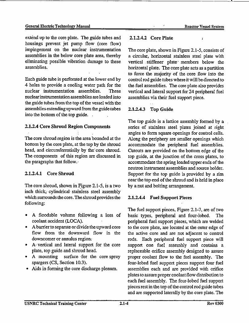
General Electric Technologyv Manual Reactor Vessel SvstemGeneral Electric Technolo�v Manual Reactor Vessel System
extend up to the core plate. The guide tubes andhousings prevent jet pump flow (core flow)impingement on the nuclear instrumentationassemblies in the below core plate area, therebyeliminating possible vibration, damage to theseassemblies.
Each guide tube is perforated at the lower end by4 holes to provide a cooling water path for thenuclear instrumentation assemblies. Thesenuclear instrumentation assemblies are loaded intothe guide tubes from the top of the vessel with theassemblies extending upward from the guide tubesinto the bottom of the top guide.
2.1.2.4 Core Shroud Region Components
The core shroud region is the area bounded at thebottom by the core plate, at the top by the shroudhead, and circumferentially by the'core shroud.The components of this region are discussed inthe paragraphs that follow.
2.1.2.4.1 Core Shroud
The core shroud, shown in Figure 2.1-5, is a twoinch thick; cylindrical stainless steel assemblywhich surrounds the core. The shroud provides thefollowing:
* A floodable volume following a loss ofcoolant accident (LOCA).
* A barrier to separate or divide the upward coreflow from the downward flow in thedowncomer or annulus region.
* A vertical and lateral support for the coreplate, top guide and shroud head.
* A mounting surface for the core sprayspargers (CS, Section 10.3).
* Aids in forming the core discharge plenum.
2.1.2.4.2 Core Plate I
The core plate, shown in Figure 2.1-5, consists ofa circular, horizontal stainless steel plate withvertical -stiffener plate" members below thehorizontal plate. The core plate acts as a partitionto force the majority of the core flow into thecontrol rod guide tubes where it will be directed tothe fuel assemblies. The core plate also providesvertical and lateral support for 24 peripheral fuelassemblies via their fuel support piece.
2.1.2.4.3 Top Guide
The top guide is a lattice assembly formed by aseries of stainless steel plates joined at rightangles to form square openings for control cells.Along the periphery are smaller openings whichaccommodate the peripheral fuel assemblies.Cutouts are provided on the bottom edge of thetop guide, at the junction of the cross plates, toaccommodate the spring loaded upper ends of theneutron instrument assemblies and source holder.Support for the top guide is provided by a rimnear the top end of the shroud and is held in placeby a nut and bolting arrangement.
2.1.2.4.4 Fuel Support Pieces
The fuel support pieces, Figure 2.1-7, are of twobasic types, peripheral and four-lobed. Theperipheral fuel support pieces, which are weldedto the core plate, are located at the outer edge ofthe active core and are not adjacent to controlrods. Each peripheral fuel support piece willsupport one fuel assembly and contains areplaceable orifice assembly designed to assureproper coolant flow to the fuel assembly. Thefour-lobed fuel support pieces support four fuelassemblies each and are provided with orificeplates to assure proper coolant flow distribution toeach fuel assembly. The four-lobed fuel supportpieces rest in the top of the control rod guide tubesand are supported laterally by the core plate. The
USNRC Technical Training Center 2.1-4 Rev 0300USNRC Technical Training Center 2.1-4 Rev 0300

General Flectrir Technolonr Manual , - Reactor Vessel SvstemG�n er21 Electric Technolo�v Manual - Reactor Vessel System
control rods pass through slots in the center of thefour-lobed fuel support pieces. A control rod andthe! four fuel assemblies which immediatelysurround it represent a control cell.
2.1.2.4.5 Core Spray Spargers
Two core spray pipes penetrate the reactor vessel1800 apart. Once inside the vessel, the pipesdivide and are routed 90°. in each direction frorr
-the point of vessel entry. The pipes (Figure 2.1-8)are directed down and then inward to penetrate theupper core shroud just below the shroud headflange. After penetrating the shroud, the lines areagain divided and proceed around the inside of theupper shroud in two semicircular headers. Spra3nozzles connected to these headers are adjusted tcprovide the-correct spray distribution to the fue:assemblies.
2.1.2.4.6 -Shroud Head -
The-shroud head, Figure 2.1-9, is rounded irshape and an integral part of the steam separato:assembly. kThe top of the shroud head contains ararray of penetrations used to channel thesteam/waterimixture exiting the core to the steanseparator standpipes which are welded to thepenetrations: The shroud head is attached to theshroud, with a special bolting arrangement, t(form the core discharge plenum. - .
2.1.2.5 Moisture Separation Assemblies
Moisture or steam separation is accomplishesinternal to the reactor yessel via a steam separatoand steam dryer. The steam separatingcomponents are discussed in the paragraphs whic]follow.
2.1.2.5.1 Steam Separator Assembly
The steam separator assembly, Figure 2.1-9consists of individual stainless steel axial flov
cyclone separators --welded to, the top of1 standpipes. Within each separator, the steam* water mixture passes swirl vanes which impart a- spin to establish a vortex separating the water
from the steam. The steam exits the top of theseparator with a steam quality between 90 to 95%.The separated water exits from under the separatorcap and flows out between the standpipes,
s draining into the downcomer annulus region,joining the feedwater.-I,,
2.1.2.5.2 Steam Dryer Assembly-
The steam dryer assembly, Figure 2.1-10, driesthe wet steam leaving the steam separators togreater than 99.9% quality. The dryer assemblyalso provides a seal between the wet steam area
I and the dry steam flowing to the steam lines. Theseal is formed by the steam dryer assembly sealskirt extending below the normal water level.
The individual dryer sections force the steam to be1 -. directed horizontally through the dryer panels.r-. The steam is forced to make a series of rapid
-- changes in direction while traversing the panels.During these direction changes, the heavier drops
i> of entrained moisture are forced to the outer wallsewhere moisture collection hooks catch and drain
the liquid to collection troughs. -From the, collection troughs the liquid is directed to the
annulus area via drain tubes.
2.1.2.6 Main Steam Outlet Penetrations
d Four, twenty-four inch, diameter steam liner nozzles are installed to direct the steam out of theo reactor vessel.
2.1.2.7 Vessel Head Penetrations
The reactor vessel head contains threepenetrations, shown in Figure 2.1-1, of which only
i, two are normally used after completion of thev initial startup testing program. The first
r. DJ3AYSUSNRC Technical Training Center 1 2.1-5 .KCV vow
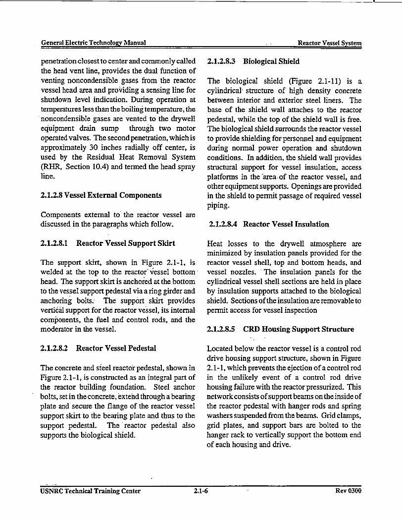
General Electric Technolo~rv Manual . - Reactor Vessel SvstemGeneal lecric echolov MaualReator essl Sste
penetration closest to center and commonly calledthe head vent line, provides the dual function ofventing noncondensible gases from the reactorvessel head area and providing a sensing line forshutdown level indication. During operation attemperatures less than the boiling temperature, thenoncondensible gases are vented to the drywellequipment drain sump through two motoroperated valves. The second penetration, which isapproximately 30 inches radially off center, isused by the Residual Heat Removal System(RHR, Section 10.4) and termed the head sprayline.
2.1.2.8 Vessel External Components
Components external to the reactor vessel arediscussed in the paragraphs which follow.
2.1.2.8.1 Reactor Vessel Support Skirt
The support skirt, shown in Figure 2.1-1, iswelded at the top to the reactor vessel bottom,head. The support skirt is anchored at the bottomto the vessel support pedestal via a ring girder andanchoring bolts; 'The support skirt providesvertiail support for the reactor vessel, its internalcomponents, the fuel and control rods, and themoderator in the vessel.
2.1.2.8.2 Reactor Vessel Pedestal
The concrete and steel reactor pedestal, shown inFigure 2.1-1, is constructed as an integral part ofthe reactor building foundation. Steel anchorbolts, set in the concrete, extend through a bearingplate and secure the flange of the reactor vesselsupport skirt to the bearing plate and thus to thesupport pedestal. The reactor pedestal alsosupports the biological shield.
2.1.2.8.3 Biological Shield
The biological shield (Figure 2.1-11) is acylindrical structure of high density concretebetween interior and exterior steel liners. Thebase of the shield wall attaches to the reactorpedestal, while the top of the shield wall is free.The biological shield surrounds the reactor vesselto provide shielding for personnel and equipmentduring normal power operation and shutdownconditions. In addition, the shield wall providesstructural support for vessel insulation, accessplatforms in the 'area, of the reactor vessel, andother equipment supports. Openings are providedin the shield to permit passage of required vesselpiping.
2.1.2.8.4 Reactor Vessel Insulation
Heat losses to the drywell atmosphere areminimized by insulation panels provided for thereactor vessel shell, top and bottom heads, andvessel nozzles. The insulation panels for thecylindrical vessel shell sections are held in placeby insulation supports attached to the biologicalshield. Sections of the insulation are removable topermit access for vessel inspection
2.1.2.8.5 CRD Housing Support Structure
Located below the reactor vessel is a control roddrive housing support structure, shown in Figure2.1-1, which prevents the ejection of a control rodin the unlikely event of a control rod drivehousing failure with the reactor pressurized. Thisnetwork consists of support beams on the inside ofthe reactor pedestal with hanger rods and springwashers suspended from the beams. Grid clamps,grid plates, and support bars are bolted to thehanger rack to vertically support the bottom endof each housing and drive.
USNRC Technical Training Center 2.1.6 Rev 0300USNRC Technical Training Center 2.1-6 Rev 0300
General Electric Technology Manual G - enReactor Vessel System
2.1.3 System Features and Interrelations uncove:- ^ - - automa
A short discussion of the system features and . core wiinterrelations this system has with other plant until itsystems is given in the paragraphs that follow. mixing
_- _ ' pump:4througi
2.1.3.1 Normal Operation r pump s(Figure 2.1-12) the heil
During normal operation, the recirculation pumps If floodand jet pumps provide forced flow of coolant withinthrough-the core. Approximately 90% bf this maintaiflow enters the fuel assemblies while a designed _.will be10% bypasses the fuel to cool other incore fuel clacomponents. The water absorbs the heat energy of the cof the fuel which increases the water temperature with w-to saturation and boils a portion of the total core cooledflow. . - upward
lower 2
The steam and water mixture exiting the core isforced to pass through the two stages of moisture -- 2.1.3.3removal in the steam separator and dryers. Thewater removed in moisture separation flows back A shortto the annulus area where it, mixes with the -has wiincoming feedwater. The dry steam exits the , paragrareactor vessel through the four main steam lines.Incoming feedwater enters the reactor vessel at six 2.1.3.3.different penetrations and is distributed viafeedwater spargers.
The fut2.1.3.2 Core Floodability region
(Figure 2.1-13) vessel c
The Emergency Core Cooling Systems (ECCS) - 2.1.3.3.and the reactor vessel design are compatible toensure that core can,, be adequately cooledfollowing a loss of coolant accident (LOCA). The Cc
I I i 4, . -cooling.The worse case loss of coolant accident, with rod dri'respect to core cooling, is a-recirculation line housingbreak with the reactor at full power. In this case,the reactor vessel water level rapidly decreases
ring the core. However, several systemstically provide makeup water to the reactorithin the shroud. r.'Water level increasesreaches the level of the top of the jet pumpsections: Water then spills out of the jetsuction- into the dannulus Aarea and outi the broken recirculation' line. -The jetuction elevation is approximately at 2/3 ofIht of the core.
ling of the reactor vessel is accomplisheda specified time frame, and if level isned at the 2/3 core coverage point, the coreadequately cooled and the integrity of theadding will be maintained. The lower 2/3,ore will be cooled because it is floodedater and the upper 1/3 of the core will beby a mixture of steam and water flowingi because of the vigorous boiling in the2/3 of the core.
System Interrelations
discussion of the interrelations this systemth other, plant. system -is given in, the.phs that follow.
.1 Fuel and Control RodsSystemr(Section 2.2)
,l and control rods are located in the coreand are vertically supported by -reactorcomponents. , ,, -_
.2 Control Rod Drive System- :(Section 2.3)
introl Rod Drive (CRD) System provides: and hydraulic driving water to the controlve mechanisms mounted in the 185 CRDIs of the reactor vessel.
-USNRC Technical Training Center '2.1-7 - Rev 03011USNRC Technical Training Center ' 2.1-7 IRev 0300
General Electric Technology Manual Reactor Vessel SystemGeneral Electric Technolosiy Manual Reactor Vessel System
2.1.3.3.3 Recirculation System (Section 2.4)
The Recirculation System provides forcedcirculation of the reactor coolant to yield higherreactor power than would -be possible undernatural circulation conditions.. The externalpumping loop of the Recirculation System takessuction from the vessel annulus and discharges tothe jet pump risers.
2.1.3.3.4 Main Steam System(Section 2.5)
The four main steam lines provide a steam pathfrom the reactor vessel to the main turbine andother balance of plant steam loads. Overpressureprotection is also provided for the reactor vesselby the 13 safety/relief valves mounted on thesteam lines. The reactor head area is also ventedto the Main Steam System.
2.1.3.3.5 Condensate and Feedwater System(Section 2.6)
The Condensate and Feedwater System provideshigh purity water to the reactor vessel to replacethe steam generated and sent to the turbine.
2.1.3.3.6 Reactor Water Cleanup System(Section 2.8)
The Reactor Water Cleanup System maintainsthe reactor coolant at high purity and provides ameans of draining water from the reactor vessel.Suction is taken from the recirculation loops andbottom head drain, anid'return is through thefeedwater lines.
*2.1.3.3.7 Reactor Vessel InstrumentationSystem (Section 3.1)
The reactor vessel level, pressure, and flowinstrumentation uses instrument lines which
penetrate the reactor vessel. Reactor vesseltemperature instrumentation uses thermocouplepads at various vessel locations and the bottomhead drain.
2.1.3.3.8 Neutron Monitoring System(Section 5.0)
The Neutron Monitoring System detectorspenetrate the reactor vessel, housings. Thedetectors are located inside the reactor core.
2.1.3.3.9 Core Spray (CS) System (Section10.3)
The Core Spray System provides for low pressurespraying of the core in the event of a LOCA. Thewater enters the reactor vessel via spray spargerslocated above the top guide.
2.1.3.3.12 Residual Heat Removal System(Section 10.4)
The low pressure coolant injection (LPCI) modeprovides flooding water to the reactor vessel viathe recirculation line.
2.1.4 Summary
Classification - Safety related system
Purposes
* To house and support the reactor.* To provide water circulation to the reactor
core to remove generated heat:* -To separate the water and steam mixture
produced in the reactor core and deliverdry steam to the main steam system.
* To provide an internal, refloodablevolume to assure core cooling capabilityfollowing a loss of coolant accident(LOCA).
USNRC Technical Training Center 2.1.8 Rev 0300I- USNRC Technical Training Center 2.1-8 Rev 0300
General Electric TechnoloL- Manual -- I Reactor Vessel SystemGeneral Electric Technolo�v Manual : Reactor Vessel System
Components
Reactor Vessel; Feedwater spargers; surveillancesample holder; jet pump assemblies; core plate;top guide; CRD housing; fuel support piece; guidetubes; moisture separator and drywell; biologicalshield; shroud; baffle plate; various penetrations.
System Interrelations
Fuel and Control Rods System; RecirculationSystem; Condensate and Feedwater System; MainSteam System; Reactor Water Cleanup System;Standby Liquid Control System, High PressureCoolant Injection System,Core Spray System;Neutron Monitoring System; Control Rod DriveSystem.
USNRC Technical Training Center 2.1-9 Rev 031111USNRC Technical Training Center -2.1-9 Rev 0300
General Electric Technology Manual Reactor Vessel SystemGeneral Electric Tecbnolo2v Manual Reactor Vessel System
USNRC Technical Training Center 2.1.10 Rev 0300USNRC Technical Training Center 2.1-10 Rey 0300
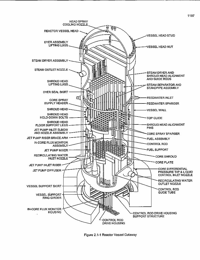
HEAD SPRAYCOOLING NOZZLE,
REACTOR VESSEL HEAD --
STEAM
-STEAM DRYER ANDSHROUD HEAD ALIGNMENTAND GUIDE RODS
-STEAM SEPARATOR ANDSTANDPIPE ASSEMBLY
SHROUD HEAD-
SHROUD HEADHOLD-DOWN BOLTS-
SHROUD HEADFLOOR SUPPORT LEGS -
JET PUMP INLET ELBOWAND NOZZLE ASSEMBLY-
JET PUMP RISER BRACE ARM
IN-CORE FLUX MONITORASSEMBLY -
JET PUMP MIXER"
RECIRCULATING WATERINLET NOZZLE'
-CONTROL ROD DRIVE HOUSINGSUPPORT STRUCTURE
Figure 2.1-1 Reactor Vessel Cutaway
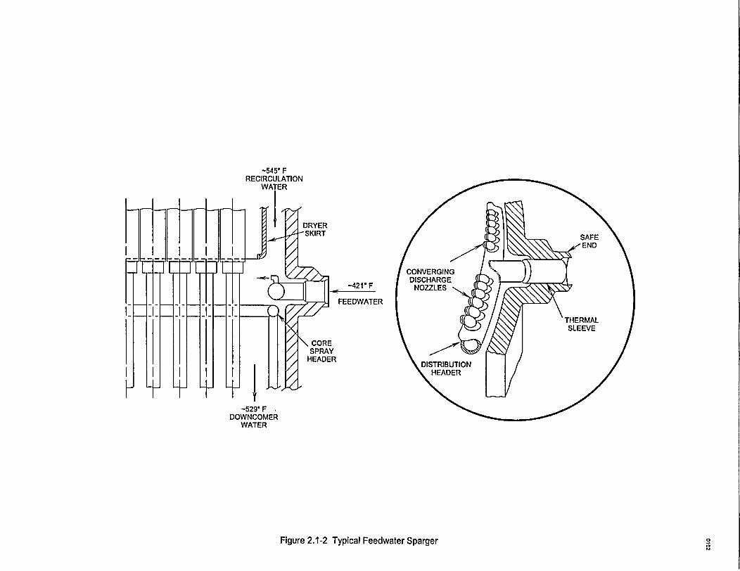
-545' FRECIRCULATION
WATER
-529' FDOWNCOMER
WATER
Figure 2.1-2 Typical Feedwater Sparger a2o
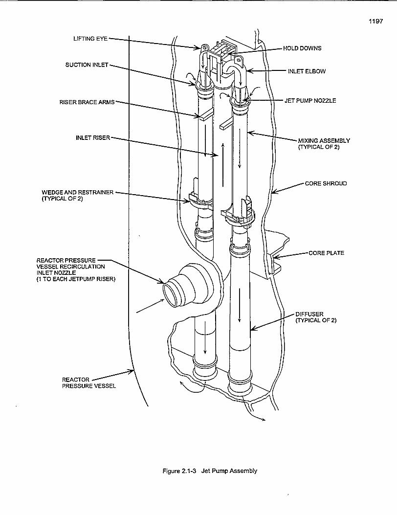
1197
WEDGE AND RESTRAINER(TYPICAL OF 2)
REACTOR PRESSUREVESSEL RECIRCULATIONINLET NOZZLE(1 TO EACH JETPUMP RISER)
Figure 2.1-3 Jet Pump Assembly

0102
SHROUD
JET PUMPDIFFUSER
Figure 2.1-4 Differential Pressure, Standby Liquid Control Line, and Shroud Support
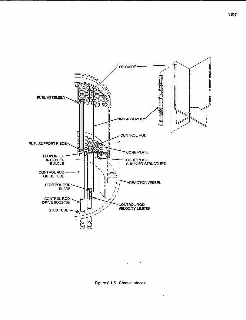
1197
I
IQ
L, lNMS ASSEMBLYL
PLATE
CONTROL ROD -GUIDE TUBE
CONTROL RODBLADE
CONTROL RODDRIVE HOUSING
STUB TUBE - VELOCITY LIMITER
bj d
9 9
I
Figure 2.1-5 Shroud Intervals
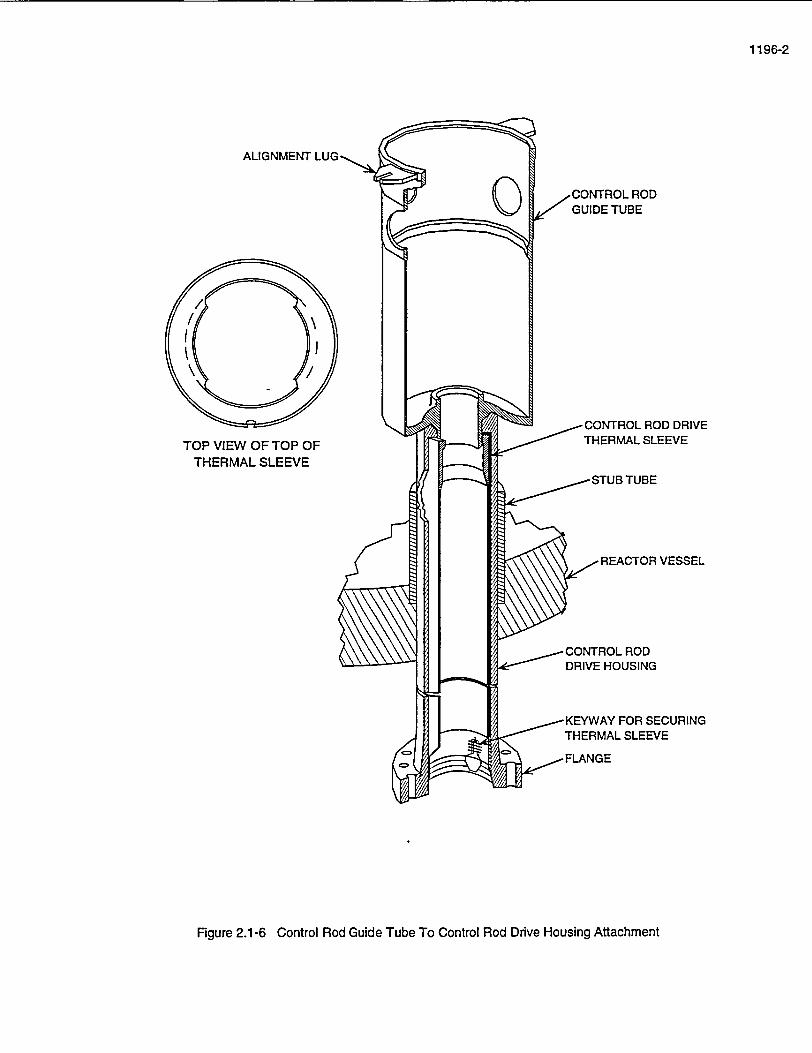
1196-2
ALIGNMENT
TOP VIEW OF TOP OFTHERMAL SLEEVE
Figure 2.1-6 Control Rod Guide Tube To Control Rod Drive Housing Attachment
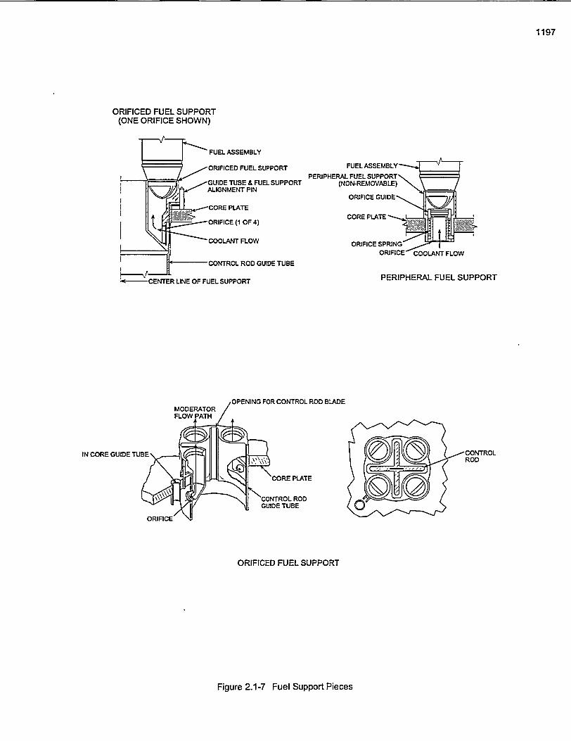
1197
ORIFICED FUEL SUPPORT(ONE ORIFICE SHOWN)
FUEL ASSEMBLY
ORIFICED FUEL SUPPORT FUEL ASSEMBLYPERIPHERAL FUEL SUPPORT
GUIDE TUBE & FUEL SUPPORT (NON-REMOVABLE)ALIGNMENT PIN
ORIFICE GUIDE
CORE PLATE
ORIFICE (1 OF 4)
COOLANT FLOW ORIFICE SPRING
ORIFICE COOLANT FLOW
CONTROL ROD GUIDE TUBE
CENTER LINE OF FUEL SUPPORT PERIPHERAL FUEL SUPPORT
OPENING FOR CONTROL ROD BLADEMODERATOR/FLOW PATH/
iGUIES TUBE~L o CONTRLCORE PLATE
CONTROL RODGUIDE TUBE
ORIFICE
ORIFICED FUEL SUPPORT
Figure 2.1-7 Fuel Support Pieces
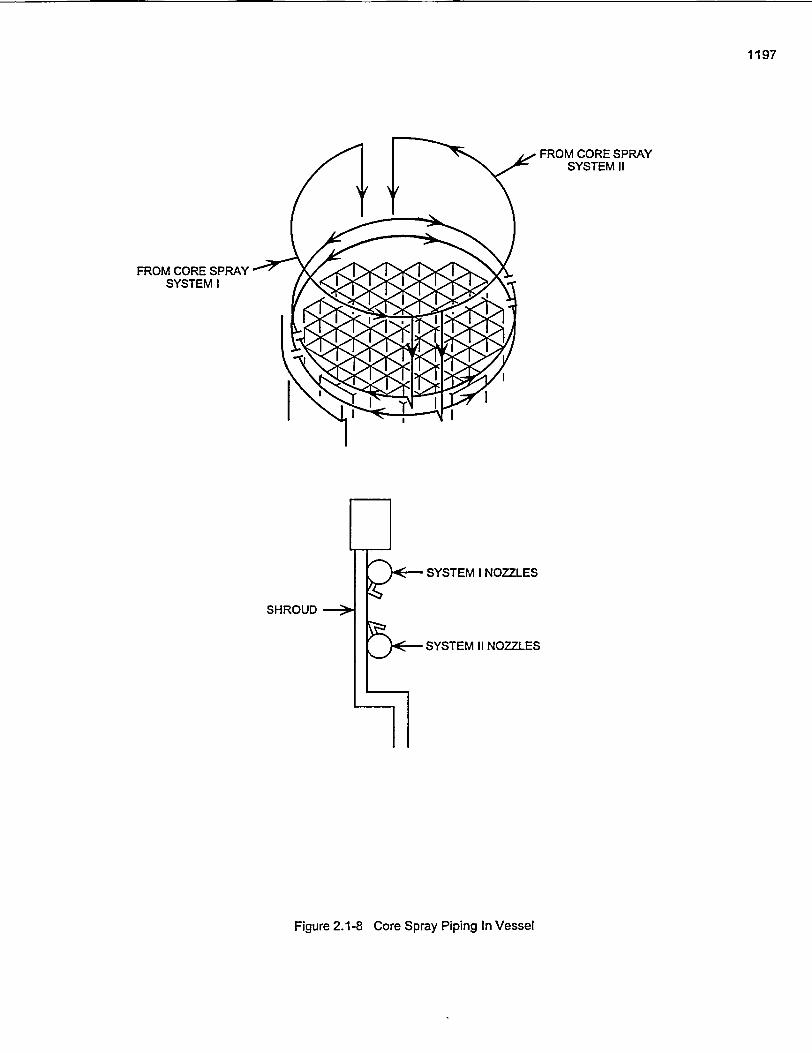
1197
FROM CORE SPRAYSYSTEMII
FROM CORE SPRAYSYSTEM I
SHROUD
SYSTEM I NOZZLES
SYSTEM II NOZZLES
Figure 2.1-8 Core Spray Piping In Vessel
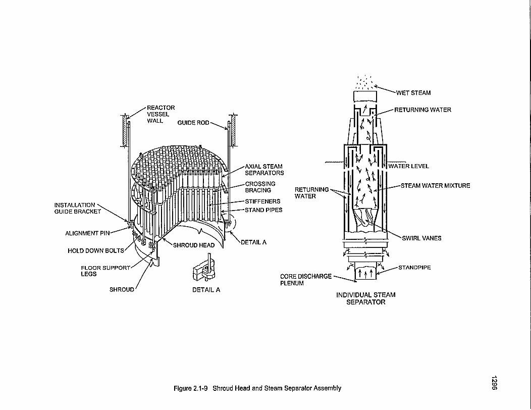
STEAM
RETURNING WATER
MIXTURERETURNING -WATER
I
S
CORE DISCHARGEPLENUM
-SWIRL VANES
SHROUDINDIVIDUAL STEAM
SEPARATOR
PDa)Figure 2.1-9 Shroud Head and Steam Separator Assembly
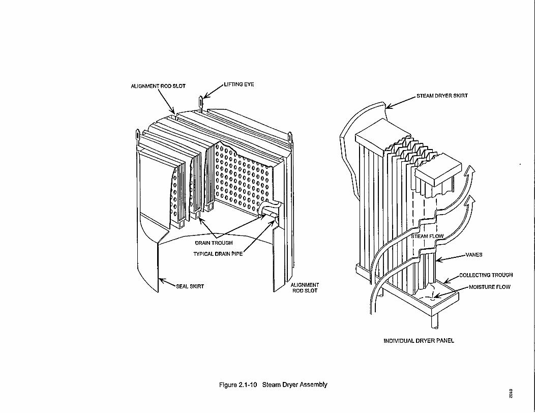
STEAM DRYER SKIRT
TROUGH
E FLOWALIGNMENTROD SLOT
INDIVIDUAL DRYER PANEL
Figure 2.1-10 Steam DryerAssemblya
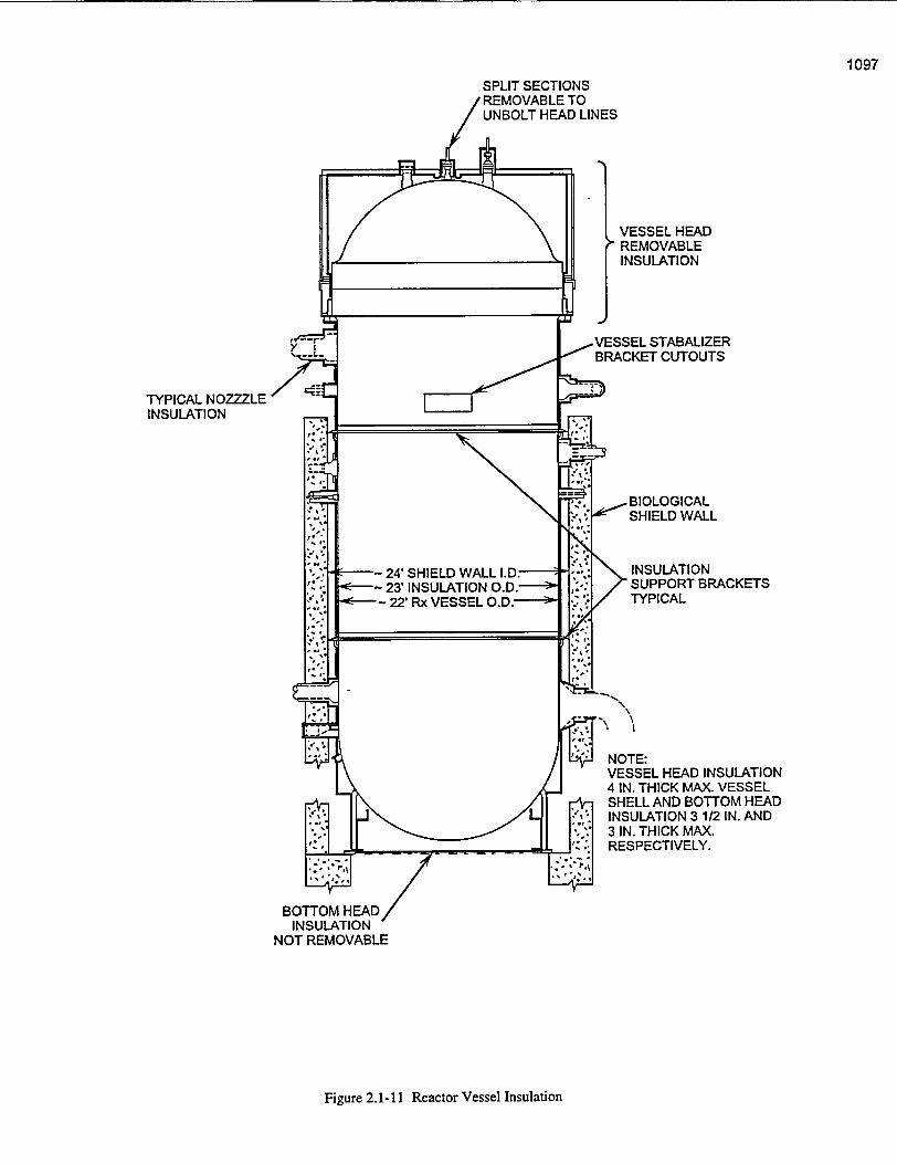
1097SPLIT SECTIONS
, REMOVABLE TOUNBOLT HEAD LINES
VESSEL STABALIZERBRACKET CUTOUTS
TYPICAL NOZZZLEINSULATION
NOTE:VESSEL HEAD INSULATION4 IN. THICK MAX. VESSELSHELL AND BOTTOM HEADINSULATION 31/2 IN. AND3 IN. THICK MAX.RESPECTIVELY.
Figure 2.1-11 Reactor Vessel Insulation
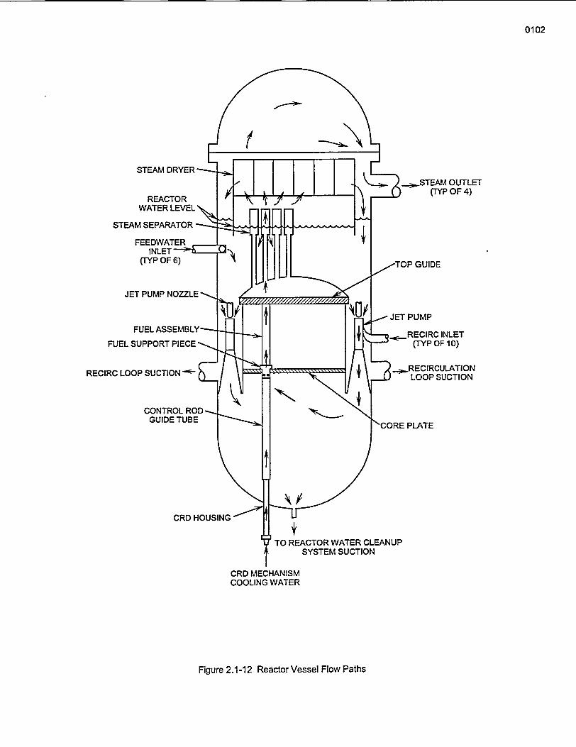
0102
STEAM DRYER-
REACTORWATER LEVEL S
STEAM SEPARATOR -
FEEDWATERINLET
(TYP OF 6)
JET PUMP NOZZLE
114~ - STEAM OUTLET(TYP OF 4)
w-TOP GUIDE
(TYP OF 10)
RECIRC LOOP SUCTION - ,-RECIRCULATIONLOOP SUCTION
GUIDE TUBE'CORE PLATE
CRD HOUSING
4TO REACTOR WATER CLEANUP
SYSTEM SUCTION
CRD MECHANISMCOOLING WATER
Figure 2.1-12 Reactor Vessel Flow Paths
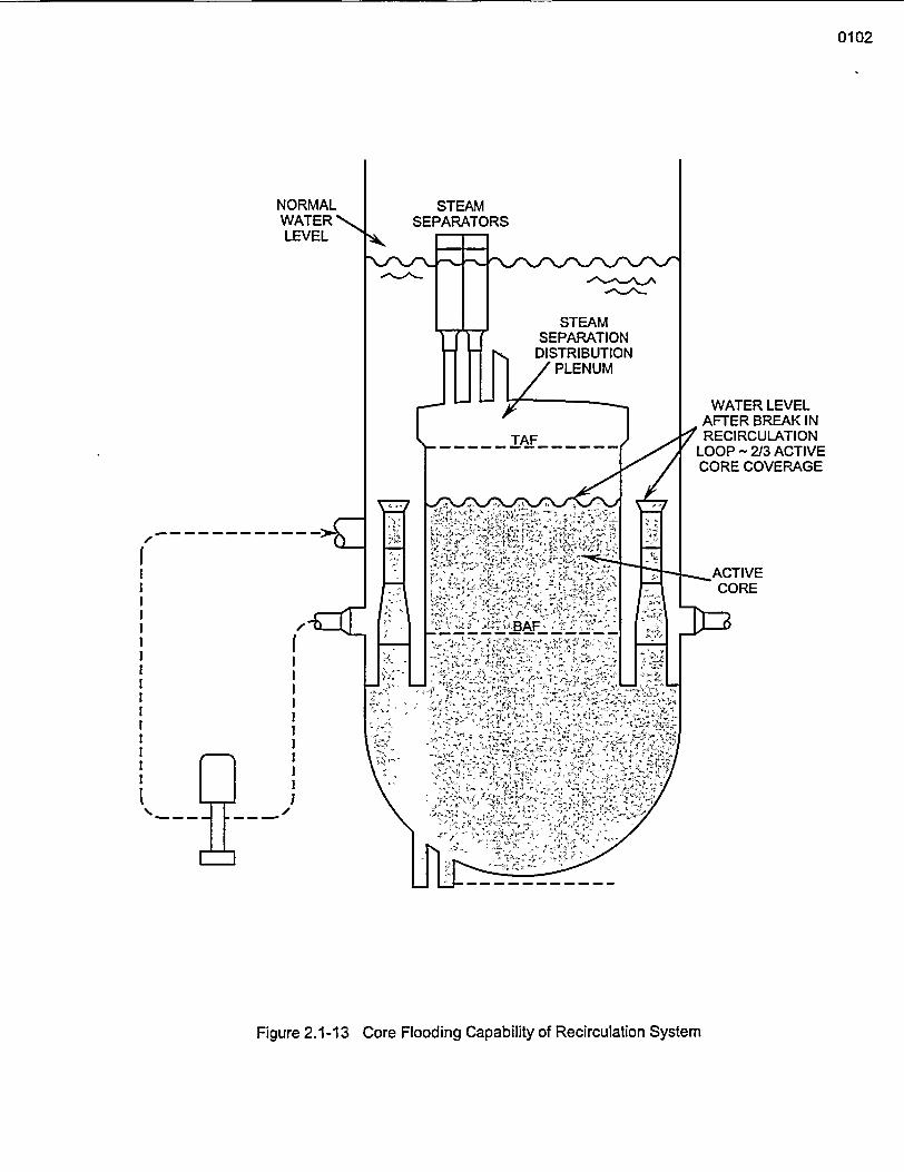
0102
NORMALWATER 'LEVEL
WATER LEVELAFTER BREAK IN
rRECIRCULATIONLOOP - 2/3 ACTIVECORE COVERAGE
I-
II
IIIl
I II II II II I
II
Figure 2.1-13 Core Flooding Capability of Recirculation System
General Electric Technology Manual Fuel & Control Rods System
Table of Contents
2.2 FUEL AND CONTROL RODS SYSTEM ........................................ 1
2.2.1 System Description ................................... 12.2.2 Component Description ................................ 1
2.2.2.1 Fuel Assembly ........................................ 1
2.2.2.1.1 Fuel Bundle .................................................2.2.2.1.2 Fuel Channel ................. 12.2.2.1.3 Fuel Rods ........... 2
2.2.2.1.4 Lower Tie Plate ........... 2
2.2.2.1.5 Upper Tie Plate ........... 2
2.2.2.1.6 Spacers ............... 32.2.2.2 Control Rods ........... . 3
2.2.2.2.1 Control Rod Blade ............... 3
2.2.2.2.2 Absorber Rods ............... 3
2.2.2.2.3 Control Rod Rollers ............... 3
2.2.2.2.4 Control Rod Velocity Limiter ............... 4
2.2.2.2.5 Control Rod Coupling ............... 4
2.2.3 System Features ........... 4
2.2.3.1 Fuel Design Considerations ........ .... 42.2.3.2 Control Rod Design Considerations ........ .... 4
2.2.3.3 Fuel Assembly Orientation ........... . 4
2.2.3.4 Bottom Entry Control Rods ........... . 5
2.2.4 System Interfaces ........... 5
2.2.4.1 Reactor Vessel System ........... . 5
2.2.4.2 Control Rod Drive System ........... . 5
2.2.5 Summary ........... 5
List of Figures
Figure 2.2-1 .. . . Fuel Assembly
Figure 2.2-2 .. . . Fuel Assembly DetailsFigure 2.2-3 .. . . Control Rod
Figure 2.2-4 .... Control Rod Velocity Limiter and CouplingFigure 2.2-5 ....... Fuel Assembly Orientation
UNC Technical Traig C r .USNRC Technical Training Center 2.2-i Rev 0100
General Electric Technology Manual I- Fuel & Control Rods SystemGeneral Electric Technology Manual Fuel & Control Rods System
2.2 FUEL AND CONTROL RODS SYSTEM
- - The purpose of the reactor fuel is to generateenergy from a nuclear fission reaction to provideheat for steam generation.The purposes of thecontrol rods are:
-1. To control reactor power level2. To control reactor power distribution
'-a3. To provide emergency shutdown capability.
The functional classification of the Fuel andControl Rods Systems is that of a safety related
-system. It also contains a component, the controlrod velocity limiter, which is an engineered safetyfeature.
2.2.2 Component Description
The major components of the Fuel and ControlRods are- discussed in the paragraphs whichfollow.
2.2.2.1 Fuel Assembly (Figure 2.2-1)
A fuel assembly consists of a fuel bundle and thefuel channel which surrounds it.. Each fuel-assembly has a dry weight of approximately 715lbs. and an overall length of 176 inches. Theassemblies are arranged in the reactor core toapproximate a right circular cylinder.
2.2.2.1.1 Fuel Bundle - - .- - -
2.2.1 System Description A fuel bundle contains fuel rods and one or more- water rods which are spaced and supported in a
The reactor core is arranged into fuel cells. Each square array by fuel rod spacers and upper andfuel cell consists of a control rod and the four fuel lower tie plates. -The square array arrangement isassemblies which immediately surround it. The dependent on - the fuel manufacturer and thefour fuel assemblies are supported by a fuel. -frequently changing design. BWR plants utilizesupport piece. Around the outer edge of the core, - three majorfuels manufacturers, (General Electriccertain fuel assemblies not immediately adjacent Company, Advanced Nuclear Fuels Corporation,
-to a -control rod are supported by individual and Brown Boveri). With the constantperipheral fuel support pieces. advancements in fuel designs it would be -very
difficult to maintain an up to date description ofThe reactivity of the core is -regulated by- all fuel types and designs. Therefore, this chaptermovement of bottom entry control rods. A control will discuss only the fuel bundle most widely usedrod blade consists of a sheathed, cruciform array - by BWRs..of vertical neutron absorber rods. The control rods -* .. -, .. -
are inserted and withdrawn from the bottom of the 2.2.2.1.2 Fuel Channelcore by the control rod drive mechanisms (Section ,2.3). - G- ,The fuel channel provides a-barrier-to separate
-- -' '. bundle flow from bypass flow, a bearing surface--To limit the rate of free fall of a control rod from and guide for the control rod blades, and protects
its fully inserted position to full out, each control the fuel rods during fuel handling operation.rod is 'equipped with a velocity limiter, located -- ,,-
below the active poison section. The fuel channels are fabricated from zircaloy-4because of its good corrosion resistance. The
* - -, , bottom end of the fuel channel makes a sliding- - . - seal fit with the lower tie plate by means of finger
springs. At the top of the channel, two diagonally. .. .
USNRC Technical Training Center 2.2.1 Rev 0100' USNRC Technical Training Center I 1. 2.2-1 -- ,~ I I-- -; Rev 0100
General Electric Technology Manual Fuel & Control Rods SystemGeneral Electric Technolo2v Manual Fuel & Control Rods System
opposite comers have welded tabs which supportthe weight of the channel from raised posts on theupper tie plate. One of the raised posts has athreaded hole to attach the channel in place witha channel fastener assembly.
Channel to channel spacing to provide a passagefor the control rod blade is maintained with theuse of spacer buttons and the channel fastenerassembly. The spacer buttons are located at thetop of the fuel channels, facing each other acrossthe control rod passage area.
2.2.2.1.3 Fuel Rods (Figure 2.2-2)
There are three different types of rods used in a8x8 fuel bundle: 54 standard fuel rods, eightfueled tie rods and two water rods.
The standard fuel rods, are approximately 160inches in length with an active fuel length of 150inches. The active fuel length consists of highdensity ceramic fuel pellets enriched in uranium-235 with some pellets having a uranium-gadolinium mixture. The remaining ten inches ofthe fuel rod contains a free volume, plenum springand a hydrogen getter. The free volume, called theplenum volume, is designed to accommodategaseous fission products which are released fromthe fuel pellets over the design life of the fuelbundle. The plenum spring maintains a constantcompressive force on the fuel pellets to maintainaxial contact between the pellets. The hydrogengetter provides protection against moisture orhydrogenous impurities in the fuel rod. Both endsof a standard fuel rod are sealed by end plugswhich slip fit into the upper and lower tie plates.
The fueled tie rods differ from the standard fuelrods in that the lower and upper end plugs arethreaded. The lower -end plugs thread into thelower tie plate while the upper end plugs extendthrough the upper tie plate and are held in placeby locking nuts. The~ third and sixth rods along
each side of the fuel bundle are fueled tierods.The fueled tie rods hold the fuel bundle togetherand support the weight of the fuel bundle duringfuel handling operations
The purpose of the water rods is to maintainorientation of the seven fuel spacers and providefor better neutron economy. The two water rodsare hollow zircaloy-2 tubes equipped withsquarebottom end plugs to prevent rotation andassure proper location of the water rods within thefuel bundle. Several holes are drilled through thetube wall at the top and bottom of the water rodsto allow coolant to flow freely throughout the rod.One of the two water rods contains welded tabsalong its outer surface to lock the fuel bundlespacers in the required axial position.
2.2.2.1.4 Lower Tie Plate
The lower tie plate, manufactured from a stainlesssteel casting, positions the fuel bundle rodslaterally and transfers the weight of the assemblyto the fuel support piece. The nose piece is used toguide the bundle into place during refuelingoperations and to direct coolant flow up throughthe fuel assembly.
A hole drilled into two sides of the lower tie plateprovide the bundle bypass flow used to cool theincore nuclear instruments.
2.2.2.1.5 Upper Tie Plate
The upper tie plate, also manufactured from astainless steel casting, provides alignment andsupport for the top of the rods within a bundle,alignment and a mating surface for the fuelchannel, and a means to attach the fuel channel tothe bundle.
The lifting handle, which is an integral part of theupper tie plate, is used for fuel assembly handling
USNRC Technical Training Center 2.2-2 Key U1UU' USNRC Technical Training Center 2.2-2 Rev OUNU
- Genieral Electric Technolonrv Manual --Fuel & Control Rods SystemnGeneral Electric Tecbnolo�v Manual -Fuel & Control Rods System
-during refueling operations and aid in verifying 2.2.2.2.2 Absorber Rodscorrect orientation within the cell. - *
2.2.2.1.6 Spacers
Seven spacers are provided, at approximately 18,-inch intervals, to give a'positive contact support-- for the fuel bundle rods and optimum rod spacing.
The spacers provide the lateral support needed tosuppress rod vibration by using inconel-x springswhich hold'the rods in place within the spacermatrix.
2.2.2.2 Control Rods (Figure 2.2-3)
Bottom entry control rods used in BWR's performthe dual function of power'shaping and reactivitycontrol. The main structural members of a controlrod are fabricated from stainless steel and consist
--of a top handle casting, a bottom casting, avertical cruciform post, and four U-shaped
i sheaths.
The end castings and 6enter post are welded intoa single skeletal structure. The U-shaped sheathsare spot welded to the center post and end castingsto form a structurally rigid housing that contains
- - the absorber rods.
Movement of the control rods is accomplished viathe Control Rod Drive System, (Section 2.3).
., ~ ~ ~ , -
The absorber rods are small stainless steel tubesfilled with boron carbide (B4C) powder, vibratorycompacted to 70% theoretical density. A total of84 absorber rods, 21 in each U-shaped sheath, arecontained in each control rod blade. To preventexcessive void regions, caused by settling of theboron carbide powder, stainless steel balls -arespaced at 16 -inch' intervals within the absorbertubes. The balls are restricted in movement byspherical crimps in the tube walls. The steel ballsallow gases to migrate within the tube but restrictB4 C movement to 16 inch sections.
2.2.2.2.3 Control Rod Rollers
Control rod alignment is accomplished with theuse of eight spherical rollers, four of which arecontained in each end casting. 'The four sphericalrollers affixed to the top end casting guide thecontrol rod blade between the four fuel assembliesby rolling on the fuel channels. The lower end ofthe control rod -is. laterally - guided by four
. spherical rollers that bear on the inner surface ofthe control rod guide tube.' The rollers are integralparts of the end castings and provide reducedresistance to-movement of the control rod.
2.2.2.2.4 Control Rod Velocity Limiter(Figure 2.2-4)
2.2.2.2.1 Control Rod Blade The control rod velocity limiter is an integral partof the bottom end'casting and is-one of the
The control rod blade (Figure 2.2-3) consists of a engineered safeguards. The velocity limiter is- sheathed, cruciform- array of vertical neutron designed to'limit the control rod velocity in the
absorber rods with a blade span of 9.75 inches. event of a rod drop accident in order to limit theThe sheaths extend the full length of the control . rate at which reactivity addition to the core can
- 'rod element and' provide a continuous iblade occur. The velocity limiter is in the form of two'Isurface.- A series of holes-in the blade sheath A nearly-mated conical elements that act as a largepermit reactor coolant to circulate freely aroundr -clearance piston inside the control rod guide tube.the absorber rods to pr6vide cooling. " - . ,
- '' ' -The velocity limiter is provided with a' ' '' - streamlined profile in the scram or upward
UNCTcnclTingCetr2.2- _e 00USNRC Technical Training Center ,-2.2-3 -Rev 0100
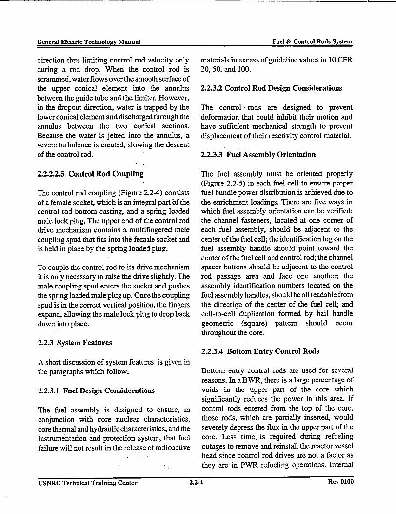
General Electric Technology Manual Fuel & Control Rods SystemGeneral Electric Technolocv Manual Fuel & Control Rods System
direction thus limiting control rod velocity onlyduring a rod drop. When the control rod isscrammed, water flows over the smooth surface ofthe upper conical element into the annulusbetween the guide tube and the limiter. However,in the dropout direction, water is trapped by thelower conical element and discharged through theannulus between the two conical sections.Because the water is jetted into the annulus, asevere turbulence is created, slowing the descentof the control rod.
2.2.2.2.5 Control Rod Coupling
The control rod coupling (Figure 2.2-4) consistsof a female socket, which is an integral part of thecontrol rod bottom casting, and a spring loadedmale lock plug. The upper end of the control roddrive mechanism contains a multifingered malecoupling spud that fits into the female socket andis held in place by the spring loaded plug.
To couple the control rod to its drive mechanismit is only necessary to raise the drive slightly. Themale coupling spud enters the socket and pushesthe spring loaded male plug up. Once the couplingspud is in the correct vertical position, the fingersexpand, allowing the male lock plug to drop backdown into place.
2.2.3 System Features
A short discussion of system features is given inthe paragraphs which follow.
2.2.3.1 -Fuel Design Considerations
The fuel assembly is designed to ensure, inconjunction with core nuclear characteristics,
score thermal and hydraulic characteristics, and theinstrumentation and protection system; that fuelfailure will not result in the release of radioactive
materials in excess of guideline values in 10 CFR20, 50, and 100.
2.2.3.2 Control Rod Design Considerations
The control 'rods are designed to preventdeformation that could inhibit their motion andhave sufficient mechanical strength to preventdisplacement of their reactivity control material.
2.2.3.3 Fuel Assembly Orientation
The fuel assembly must be oriented properly(Figure 2.2-5) in each fuel cell to ensure properfuel bundle power distribution is achieved due tothe enrichment loadings. There are five ways inwhich fuel assembly orientation can be verified:the channel fasteners, located at one corner ofeach fuel assembly,< should be adjacent to thecenter of the fuel cell; the identification lug on thefuel assembly handle should point toward thecenter of the fuel cell and control rod; the channelspacer buttons should be adjacent to the controlrod passage area and face one another; theassembly identification numbers located on thefuel assembly handles, should be all readable fromthe direction of the center of the fuel cell; andcell-to-cell duplication formed by bail handlegeometric (square) pattern should occurthroughout the core.
2.2.3.4 Bottom Entry Control Rods
Bottom entry control rods are used for severalreasons. In a BWR, there is a large percentage ofvoids in the upper part of the core whichsignificantly reduces the power in this area. Ifcontrol rods entered from the top of the core,those rods, which are partially inserted, wouldseverely depress the flux in the upper part of thecore. Less- time, is required during refuelingoutages to remove and reinstall the reactor vesselhead since control rod drives are not a factor asthey are in PWR refueling operations. Internal
USNRC Technical Training Center 2.2-4 Rev 0100USNRC Technical Training Center 2.2-4 Rev 0100
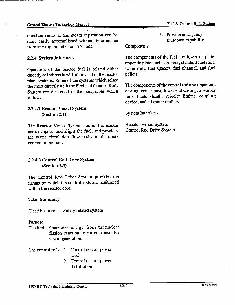
V-smernIr El1ectric Technnolory Manual Fuel &t Control Rods System(�np,-�l I�1e�'tr� Tgq'hnnlo�rv Manna! Fuel & Control Rods System
moisture removal and steam separation can bemore easily accomplished without interferencefrom any top mounted control rods.
2.2.4 System Interfaces
Operation of the reactor fuel is related eitherdirectly or indirectly with almost all of the reactorplant systems. Some of the systems which relatethe most directly with the Fuel and Control RodsSystem are discussed in the paragraphs whichfollow.
2.2.4.1 Reactor Vessel System(Section 2.1)
The Reactor Vessel System houses the reactorcore, supports and aligns the fuel, and providesthe water circulation flow paths to distributecoolant to the fuel.
3. Provide emergencyshutdown capability.
Components:
The components of the fuel are: lower tie plate,upper tie plate, fueled tie rods, standard fuel rods,water rods, fuel spacers, fuel channel, and fuelpellets.
The components of the control rod are: upper endcasting, center post, lower end casting, absorberrods, blade sheath, velocity limiter, couplingdevice, and alignment rollers
System Interfaces:
Reactor Vessel SystemControl Rod Drive System
2.2.4.2 Control Rod Drive System(Section 2.3)
The Control Rod Drive System provides themeans by which the control rods are positionedwithin the reactor core.
2.2.5 Summary
Classification: Safety related system
Purpose:The fuel: Generates energy from the nuclear
fission reaction to provide heat forsteam generation.
The control rods: 1. Control reactor powerlevel
2. Control reactor powerdistribution
K�Y uiuuUSNRC Technical Training Center 2.2-5USNRC Technical Training Center 2.2-5 Rev 0100
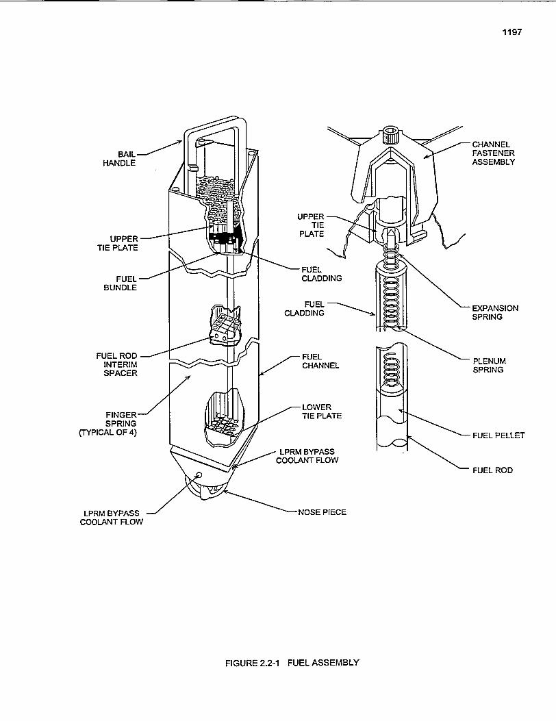
1197
BAIL-HANDLE
UPPERTIE PLATE
FUEL -BUNDLE
CHANNELFASTENERASSEMBLY
EXPANSIONSPRING
PLENUMSPRING
FUEL PELLET
FUEL ROD
FUEL RODINTERIMSPACER
FINGER-SPRING
(TYPICAL OF 4)
LPRM BYPASSCOOLANT FLOW
FIGURE 2.2-1 FUEL ASSEMBLY
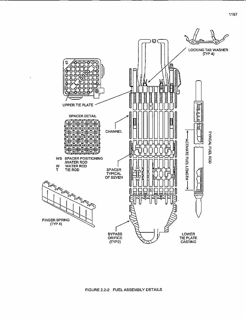
1197
LOCKING TAB WASHER(TYP 4)
SPACER DETAIL
a B E V i
t)'-t VD) QiQ000:XK:
, Q * Mi ;4 Q D Bo a epigmi ,
CHANNEL
-4
m'1
mI-mz-I
-:
0
r-T
cmI-
0WS
WT
SPACER POSITIONINGIWATER RODWATER RODTIE ROD SPACER
TYPICALOF SEVEN
FINGER SPRING(TYP 4)
BYPASSORIFICE(TYP2)
LOWERTIE PLATECASTING
FIGURE 2.2-2 FUEL ASSEMBLY DETAILS
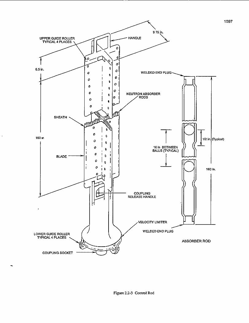
1097
UPPER GUIDE ROLLERTYPICAL 4 PLACES \
SHEATH
160 an
WELDED END PLUG
NEUTRON ABSORBER/Z RODS
16in BETVABALLS (TYP
COUPLINGRELEASE HANDLE
VELOCITY LIMITER
WELDED END PLU
BLADE
I
L��-l �ti
}2in
EENmCAL)
I16(
{ (Typical)
) in.
LOWER GUIDE ROLLERTYPICAL 4 PLACES ,
ABSORBER ROD
COUPLING SOCKET
Figure 2.2-3 Control Rod
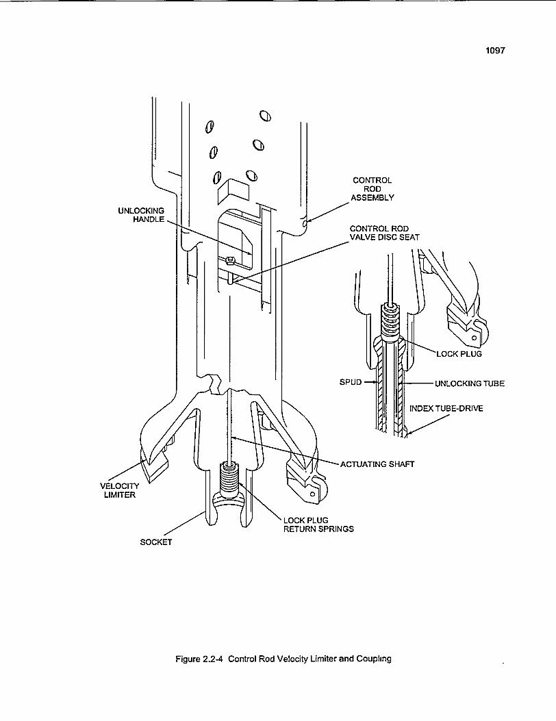
1097
00
f$1~
UNLOCKINGHANDLE
CONTROLROD
ASSEMBLY
CONTROL RODVALVE DISC SEAT
SPUD
-ACTUATING SHAFT
VELOCITYLIMITER
LOCK PLUGRETURN SPRINGS
SOCKET
Figure 2.2-4 Control Rod Velocity Limiter and Coupling
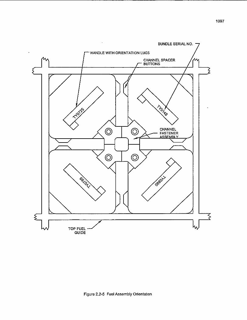
1097
BUNDLE SERIAL NO.
'HANDLE WITH ORIENTATION LUGS
CHANNEL SPACERr BUTTONS /I
TOP FUELGUIDE
Figure 2.2-5 Fuel Assembly Orientabon
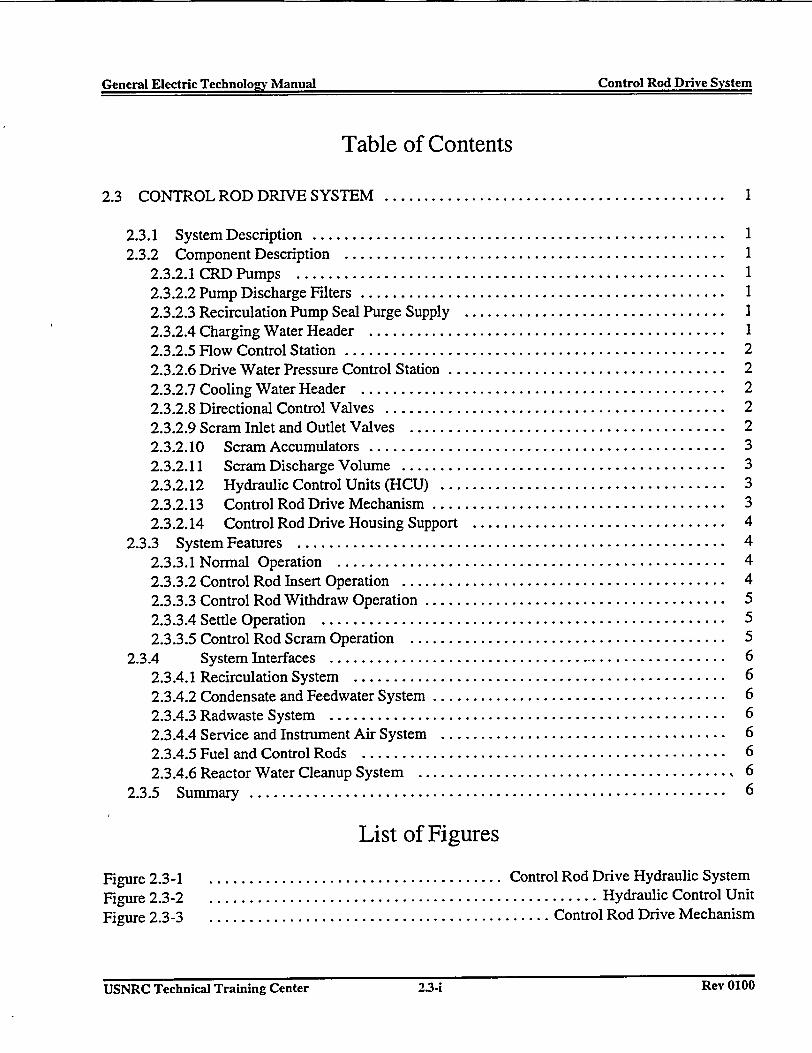
General Electric Technolog-v Manual Control Rod Drive SystemGeneral Electric Technolo2v Manual Control Rod Drive System
Table of Contents
2.3 CONTROL ROD DRIVE SYSTEM ........................................... 1
2.3.1 System Description ..................2.3.2 Component Description ..............
2.3.2.1 CRD Pumps ....................2.3.2.2 Pump Discharge Filters ............2.3.2.3 Recirculation Pump Seal Purge Supply2.3.2.4 Charging Water Header ...........2.3.2.5 Flow Control Station ..............2.3.2.6 Drive Water Pressure Control Station .2.3.2.7 Cooling Water Header ............2.3.2.8 Directional Control Valves .........2.3.2.9 Scram Inlet and Outlet Valves ......2.3.2.10 Scram Accumulators ...........2.3.2.11 Scram Discharge Volume .......2.3.2.12 Hydraulic Control Units (HCU) . .
..................................
..................................
..................................
..................................
.................................
..................................
..................................
..................................
..................................
..................................
..................................
..................................
..................................
..................................
1111112222233332.3.2.13 Control Rod Drive Mechanism .
2.3.2.14 Control Rod Drive Housing Support .................. . 42.3.3 System Features ................ ...................................... 4
2.3.3.1 Normal Operation .............................. . 42.3.3.2 Control Rod Insert Operation ...................... . 42.3.3.3 Control Rod Withdraw Operation ........ ............. . 52.3.3.4 Settle Operation ............................... . 52.3.3.5 Control Rod Scram Operation ......... ............ .5
2.3.4 System Interfaces ............ ....................................... 62.3.4.1 Recirculation System .............................. . 62.3.4.2 Condensate and Feedwater System ........ ............ . 62.3.4.3 Radwaste System ............................... . 62.3.4.4 Service and Instrument Air System ........ ........... . 62.3.4.5 Fuel and Control Rods .............................. . 62.3.4.6 Reactor Water Cleanup System ....................................... 6
2.3.5 Summary . ........................................................... 6
List of Figures
Figure 2.3-1Figure 2.3-2Figure 2.3-3
..................................... Control Rod Drive Hydraulic System
................................................. Hydraulic Control Unit
........................................... Control Rod Drive Mechanism
USNRC Technical Training Center 2.3.1 Rev 0100USNRC Technical Training Center 2.3-i Rev 0100
. -General Electric Technology Manual Control Rod Drive System- !General Electric Technology Manual - Control Rod Drive System
* 2.3 CONTROL ROD DRIVE SYSTEM
The purposes of the Control Rod Drive (CRD)System are to position control rods to: -
1. Change reactor power2. Rapidly shut down the reactor.
The'Control Rod Drive System is functionally-classified as a safety related system because of theRiactori Protection -System ' scram' function.Portions of the Control Rod Drive System notrelated to 'the scram function are -functionallyclassified as power generation equipment.
2.3.1 System Description
The control rod drive mechanism, Figure 2.3-1, isa double acting, mechanically'latched hydrauliccylinder using reactor quality water as operatingfluid.
-Control :'r6d movement is accomplished byadmitting' water under pressure' into theappropriate 'part' of the control rod 'drivemechanism. The control rod drive mechanismmovement is transmitted to the control rod bladewhich is coupled to' the drive mechanism. The
headers which supply hydraulic fluid to the 137control rod drive mechanisms.
2.3.2 Component Description,
The major components of the CRD system arediscussed in the paragraphs which follow.
23.2.1- CRD Pumps- '-
The -Control Rod Drive -System~has two fullyredundant pumps, each with a rated capacity of
-200 gpm.at 1600 psig. The two 100% capacitypumps are motor driven, multistage'centrifugalpumps. One pump is normally in service, takingsuction from'the'condensate storage tank andproviding approximately 50 to 60 gpm flow rate.The other pump is in standby.
2.3.2.2 Pump Discharge Filters
The control'-rod' drive pump'discharge -filters
prevent -foreign material- from entering. thehydraulic tcontriol units.-The 'two 100% capacityfilters are redundant, with one in operation and theother manually valved out of service.
2.3.2.3 Recirculation Pump Seal Purgedrive mechanism is capable of inserting or - Supply-withdrawing a control rod at a slow controlled rateas well as, providing scram insertion for rapid The control rod drive system supplies a regulated
l shutdown of the reactor. ' . 3 to 5 gpm flow t6 each of the recirculation pumps- - * -''^(Section 2.4). -The cool,' clean, high quality water'The t Control Rod Drive Hydraulic System - minfrniz'es the'criid buildup in the recirculationprovides 'the hydraulic fluid-(water) fornormal -iipumpseals thus increasing seal life.'"insertion '--and withdrawal of- control' rods. - - ' -''Additionally, the Control Rod Drive Hydraulic `'-2.3.2.4 Charging Water Header
- -Systefi provides cooling water for the control rod ' 'I
- drive-mechanisms and recirculation, pump' seals The charging water header supplies the high'and maintains a source of stored eiergy for the pr'essure' water reqjuired for -charging the waterscram function. Figure 2.3-1 shows the basic ' side' of the scram accumulaiors on the hydraulichydraulic water flow path which consists of -'control units.'centrifugal pumps, filters, control valves and ,- - I-
.... ........
I USNRC Technical Training Center USNRC~~~~ ~ ~ ~ ~ Tehia:riigCntr23-Rv00.- 2.3-1 - Rev 0100
General Electric Technology Manual Control Rod Drive SystemGeneral Electric Technolo2y Manual Control Rod Drive System
2.3.2.5 Flow Control Station
The flow control station consists of a flowelement, a transmitter, a flow controller, and two100% capacity air operated flow control valves.
The flow controller establishes a flow setpoint, setby the operator to maintain the proper coolingwater header flow. The flow control valve willautomatically react to deviations in the flow,sensed by the flow element, and make necessaryadjustments in flow from the drive water pump.Only one flow control valve is in service with theother manually valved out.,
2.3.2.6 Drive Water Pressure Control Station
The drive water pressure control station consistsof a motor operated valve and two sets ofstabilizing valves.
.The motor operated pressure control valve isthrottled to maintain approximately 260 psidabove reactor pressure in the drive water header.Drive water, as its name implies, is the operatinghydraulic fluid used for normal movement of thecontrol rod drive mechanism and its associatedcontrol rod into or out of the core. For this reason,there is flow in the drive water header only duringdrive movement.
Two duplicate sets of stabilizing valves areinstalled in parallel with one set in operation andone in standby. Each set consists of two solenoidoperated valves. The stabilizing valves bypass aregulated flow around the motor operated pressurecontrol valve equivalent to the flow needed forboth insertion and withdrawal of a control rod.
When a control rod is moved, the Reactor ManualControl System (Section.7.1) signals one of thestabilizing valves to close and its flow is divertedto the drive water header. One of the solenoidoperated valves is used for drive insertion and the
other for drive withdrawal. Thus flow remainsconstant in the system.
2.3.2.7 Cooling Water Header
The Control Rod Drive System cooling waterheader supplies cooling water, .25 gpm/drive, toeach control rod drive mechanism. The coolingwater being supplied to the drive mechanisms isused to cool the drives when they are stationary,prolonging the life of the seals on the drive piston.
The cooling water pressure is maintained slightlyabove reactor pressure by the action of theautomatic flow control valve and the pressuredrop across the drive water pressure controlstation.
2.3.2.8 Directional Control Valves
The purpose of the directional control valves is todirect drive and exhaust water for control rodmovement. The Reactor Manual Control System(Section 7. 1), upon command, provides the propersequencing and duration of signals used to operatethe directional control valves.
2.3.2.9 Scram Inlet and Outlet Valves,
The scram inlet and outlet valves control the flowof water necessary for rapid rod insertion. Thescram valves are held closed during reactoroperation by instrument air pressure being appliedto the tops of their actuators. The scram valvesopen by removing the air pressure and'allowingspring force to push the valve open. Control of theair supplied to the scram valves is accomplishedwith the use of scram solenoid valves. The scramsolenoid valves are normally energized andcontrolled -by the Reactor Protection System(Section 7.3).
USNRC Technical Training Center 2.3-2 Rev 0100USNRC Technical Training Center 2.3-2 Rev 0100
General Electric Technology Manual I , Control Rod Drive SystemGeneral Electiic Technology Manual Control Rod Drive System
2.3.2.10 Scram Accumulators
The scram accumulator is a piston type wateaccumulator pressurized by a volume of N, gas iia N; - cylinderi The accumulators and 'theiinstrumentation 'occupy the lower part of thehydraulic control units. The piston in the scranaccumulator forms a barrier between the 'hig]
- - pressure N, gas used as the source of stored efiergiand the water used to initiate the' scram. .Undenormal plant operating conditions the piston is ijthe full down position. The' control -rod driveplump: continuously pressurizes the scranaccumulators through the charging water headei
1-2.3.2.11 Scram Discharge Volume
The scram discharge volume consists of headepiping which connects to each Hydraulic ContraUnit and drains into two independent, redundaninstrument volumes. The scram discharge volum
'is sized to receive and, contain approximnatel,i twice the volume of water discharged by all 13$- control rod drive mechanisms -during 'a: scrarr
- independent of the instrument volumes. Durin~normal operation the'scram discharge volume i
2 empty, and vented to atmosphere byair operatesglobe valves' that automatically close on a scransignal from the Reactor Protection System.
1. Stores energy (accumulators) and contains thevalving necessary (scrar inlet and outlet
r valves) to permit the control rod to scram.
r 2. Contains valving -necessary for' normalmovement (solenoid - operated '-directional
a * control valves). -
y '3. Provides a cooling water flow path to ther control rod drive mechanism.a
2.3.2.13 Control Rod Drive Mechanism
Thfe control rod drive 'mechanism (CRDM) is'- shown functionally in Figure 2.3-1. Figuie 2.3-3,illustrates the normal latch' conditi6n of themechanism and the cooling water flow path.
r1 The CRDM is a double acting, mechanically.t latched hydraulic cylinider assemnbly using reactore quality water as its operating fluid f6r normal and
scram -control rod operation.' -The 'CRDM is7 capable of inserting or withdrawing a control rodl, at a slow, controlled rate, as well as providing ag rapid inseftion in- the' event of an off n6rmals condition. A locking mechanism in the CRDMI permits the control rod to be positioned at 6 incha increments of stroke and to be -held in' a set
position for indefinite periods of time:'
C2.3.2.12 Hydraulic Control Units (HCU) The basic parts of a CRDM consists of a control--'.rod -drive' housing, an outer tube, an-inner
The HCU,- shown'in Figure 2.3-2, includes all the,-: cylinder, an index tube, a piston tube, a drivehydraulic, electrical and pneumatic equipment '-piston,acolletlockingmechanism,andaposition
necessary -to move' one control 'rod "drive indicating tube. ' '. - -
mechanism during normal or scram operation.There are 137 HCU's, divided into approximately Control rod position is -obtained from reedtwo equal sets, which are located in the reactor switches mounted inside of the position indicationbuilding ofi-each'side of the dryw'ell.' probe, that open or close during rod movement.
The reed switches are provided at three inch
Each HCU perforrns three specific functions: increments of drive piston travel. Since a notch issix inches. indication is available for each halfnotch of rod travel. Even numbered readouts, 00to 48, are provided at each latched drive position.I -
USNRC Technical Training Center USNRC Technical Training Center '2.3-3 -� - Rev U1IJU2.3-3 - -1 --- Rev 0100
General Electric Technology Manual Control Rod Drive SvstemGeneral Electric Technoloev Manual Control Rod Drive System
Odd numbered readouts, 01 to 47, indicate themidpoints between the latched positions.
The outer tube, inner cylinder and flange is asingle piece unit. The flange provides the meansof mounting the CRDM to the control rod drivehousing flange. The outer tube and inner cylinderform an annulus through which water is applied tothe collet locking mechanism to unlock the indextube.
The drive piston and index tube provide thedriving link with the control rod as well asnotches for the collet locking mechanism fingers.The notches are machined to engage the colletfingers, providing 25 increments (at 6 inchintervals) at which a control rod may bepositioned.
The collet locking mechanism is contained in theupper portion of the outer tube and ensures theindex tube is locked to hold the control rod at aselected position in, the reactor core.
2.3.2.14 Control Rod Drive HousingSupport
The control rod drive housing support network isan engineered safety feature designed to limit theejection of a control rod to less than 3 inches inthe unlikely event of a control rod drive housingfailure with the reactor pressurized. This networkconsists of support beams on the inside of the,,.reactor pedestal, with hanger rods and springwashers suspended from beams.
2.3.3 System Features
A short discussion of system features is given inthe paragraphs which follow:
2.3.3.1 Normal Operation(Figure 2.3-3)
During normal power operation, the control roddrive system is providing cooling water flow to allof the control rod drive mechanisms and bothrecirculation pumps. Cooling water enters throughthe insert port of each CRDM and is allowed toflow between the outer tube and thermal sleevevia a cooling water orifice. The cooling waterflow rate is regulated by the restricting orifice andallows approximately .25 gpm to pass. Coolingwater is provided to ensure longer seal andbushing life. . .
Cooling water flow is normally maintained toeach CRDM at all times except when a controlrod is moved.
2.3.3.2 Control Rod Insert Operation
Control rod insert operation is accomplished byopening both insert directional control valves 121and 123. Opening of the directional control valvesapplies drive water pressure to the under side ofthe drive piston and allows water from the areaabove the drive piston to exhaust to the exhaustheader. The water displaced into the exhaustheader is then returned to the reactor vessel.
The differential pressure that is created across thedrive piston forces the drive mechanism into thecore, inserting the control rod. With the drivemoving upward, the collet fingers move outwardand provide no restriction to the drive.
2.3.3.3 Control Rod Withdraw Operation
Control rod withdraw requires a brief insert signal(Section 2.3.3.2) to relieve the axial load on thecollet locking mechanism. The area of the colletpiston is designed to ensure unlocking is notpossible when opposed by the forces of its colletspring, the weight of the drive components, and
USNRC Technical Training Center 2.3-4 Rev 0100USNRC Technical Training Center 2.3-4 Rev 0100
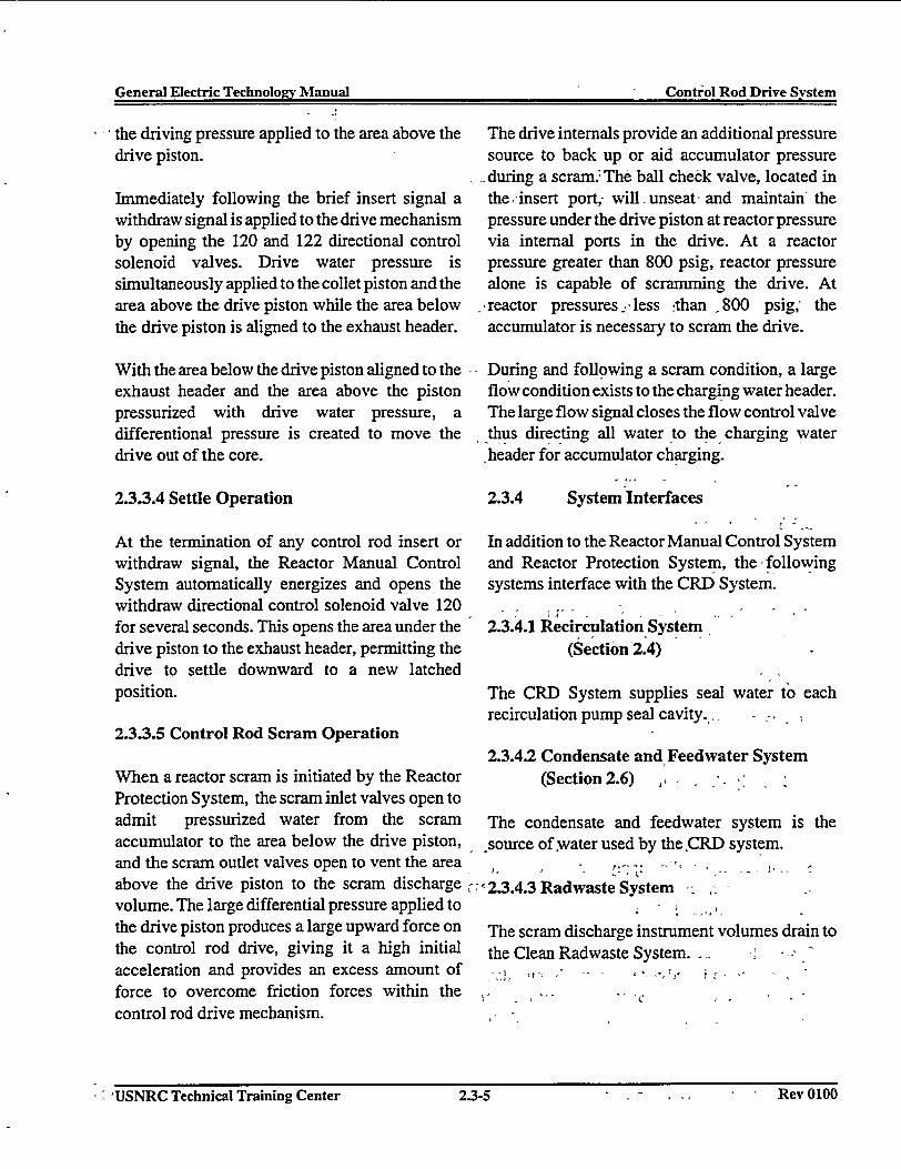
General Electric Technology Manual Control Rod Drive SystemGeneral Electric TechnoIo�y Manual Control Rod Drive System
the driving pressure applied to the area above thedrive piston.
Immediately following the brief insert signal awithdraw signal is applied to the drive mechanismby opening the 120 and 122 directional controlsolenoid valves. Drive water pressure issimultaneously applied to the collet piston and thearea above the drive piston while the area belowthe drive piston is aligned to the exhaust header.
With the area below the drive piston aligned to theexhaust header and the area above the pistonpressurized with drive water pressure, adifferentional pressure is created to move thedrive out of the core.
2.3.3.4 Settle Operation
At the termination of any control rod insert orwithdraw signal, the Reactor Manual ControlSystem automatically energizes and opens thewithdraw directional control solenoid valve 120for several seconds. This opens the area under thedrive piston to the exhaust header, permitting thedrive to settle downward to a new latchedposition.
2.3.3.5 Control Rod Scram Operation
When a reactor scram is initiated by the ReactorProtection System, the scram inlet valves open toadmit pressurized water from the scramaccumulator to the area below the drive piston,and the scram outlet valves open to vent the areaabove the drive piston to the scram dischargevolume. The large differential pressure applied tothe drive piston produces a large upward force onthe control rod drive, giving it a high initialacceleration and provides an excess amount offorce to overcome friction forces within thecontrol rod drive mechanism.
The drive internals provide an additional pressuresource to back up or aid accumulator pressureduring a scram.; The ball check valve, located inthe -insert port, will unseat and maintain' thepressure under the drive piston at reactor pressurevia internal ports in the drive. At a reactorpressure greater than 800 psig, reactor pressurealone is capable of scramming the drive. At
"reactor pressures- less :than 800 psig, theaccumulator is necessary to scram the drive.
During and following a scram condition, a largeflow condition exists to the charging water header.The large flow signal closes the flow control valvethus directing all water to the charging waterheader for accumulator charging.
2.3.4 System Interfaces
In addition to the Reactor Manual Control Systemand Reactor Protection System, the-followingsystems interface with the CRD System.
2.3.4.1 Recirculation System(Section 2.4)
The CRD System supplies seal water to eachrecirculation pump seal cavity., -
2.3.4.2 Condensate and Feedwater System(Section 2.6) i,
The condensate and feedwater system is thesource of water used by the ,CRD system.
2,c2.3.4.3 Radwaste System , -
The scram discharge instrument volumes drain tothe Clean Radwaste System. L -
I - USNRC Technical Training Center 2.3-5 . - -I -1 . I Rev 0100
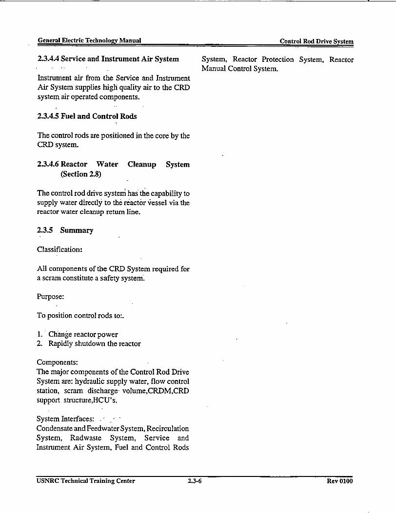
General Electric Technology Manual Control Rod Drive qvqtemGenerl Elctri Tecnolo~ Manal Cntrn Rnd_ Drive 5-~
2.3.4.4 Service and Instrument Air System System, Reactor Protection System, Reactor- -Manual Control System.
Instrument air from the Service and InstrumentAir System-supplies high quality air to the CRDsystem air operated components.
2.3.4.5 Fuel and Control Rods
The control rods are positioned in the core by theCRD system.
2.3.4.6 Reactor Water Cleanup System(Section 2.8)
The control rod drive systemn has the capability tosupply water directly to the reactor vressel via thereactor water cleanup return line.
2.3.5 Summary
Classification:
All components of the CRD System required fora scram constitute a safety system.
Purpose:
To position control rods to:.
1.' Change reactor power2. Rapidly shutdown the reactor
Components:The major components of the Control Rod DriveSystem are: hydraulic supply water, flow controlstation, scram discharge- volume,CRDM,CRDsupport structure,HCU's.
System Interfaces: -
Condensate and Feedwater System, RecirculationSystem, Radwaste System, Service andInstrument Air System, Fuel and Control Rods
USNRC Technical Training Center 2.3.6 Rev 0100USNRC Technical Training Center 2.3-6 Rev 0100
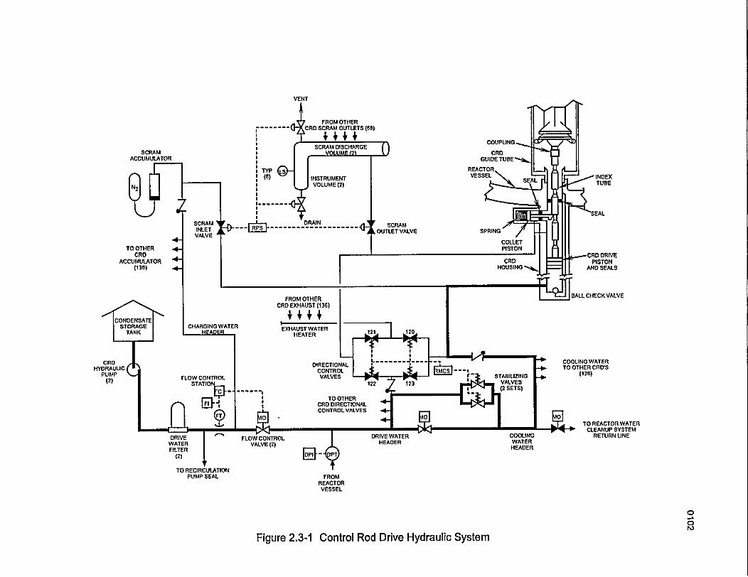
FROM OTHER
COUPLING.
SCRAMACCUMULATOR
INDEXTUBE
TO OTHERCRD
ACCUMULATOR(136)
I BALL CHECK VALVEFROM OTHER
CRD EXHAUST (136)
EXHAUST WATERHEATER
DIRECTIONALCONTROLVALVES
COOLING WATERTO OTHER CRD'S
(136)
DRIVE IWATERFILTER
(2)
TO RECIRCULATIONPUMP SEAL
DRIVE WATER COOLINGHEADER WATER
HEADER
FROMREACTORVESSEL
TO REACTOR WATERCLEANUP SYSTEM
RETURN LINE
0
01`0
Figure 2.3-1 Control Rod Drive Hydraulic System
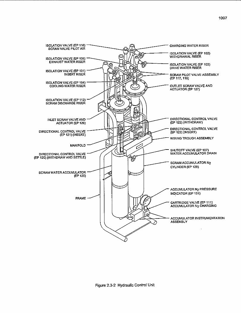
1097
ISOLATION VALVE (EP 116)SCRAM VALVE PILOT AIR
ISOLATION VALVE (EP 105)EXHAUST WATER RISER
ISOLATION VALVE (EP 101)INSERT RISER
ISOLATION VALVE (EP 104)COOLING WATER RISER
ISOLATION VALVE (EP 112)SCRAM DISCHARGE RISER
INLET SCRAM VALVE AND'ACTUATOR (EP 126)
DIRECTIONAL CONTROL VALVE(EP 121) (INSERT)
MANIFOLD
DIRECTIONAL CONTROL VALVE(EP 120) (WITHDRAW AND SETTLE)
SCRAM WATER ACCUMULATOR(EP 125)
FRAME
CHARGING WATER RISER
ISOLATION VALVE (EP 102)WITHDRAWAL RISER
ISOLATION VALVE (EP 103)DRIVE WATER RISER
SCRAM PILOT VALVE ASSEMBLY(EP 117.118)
OUTLET SCRAM VALVE ANDACTUATOR (EP 127)
DIRECTIONAL CONTROL VALVE(EP 122) (WITHDRAW)
DIRECTIONAL CONTROL VALVE(EP 123) (INSERT)
'WIRING TROUGH ASSEMBLY
SHUTOFF VALVE (EP 107)WATER ACCUMULATOR DRAIN
SCRAM ACCUMULATOR N2CYLINDER (EP 128)
ACCUMULATOR N2 PRESSUREINDICATOR (EP 131)
CARTRIDGE VALVE (EP 111)ACCUMULATOR N2 CHARGING
ACCUMULATOR INSTRUMENTATIONASSEMBLY
Figure 2.3-2 Hydraulic Control Unit
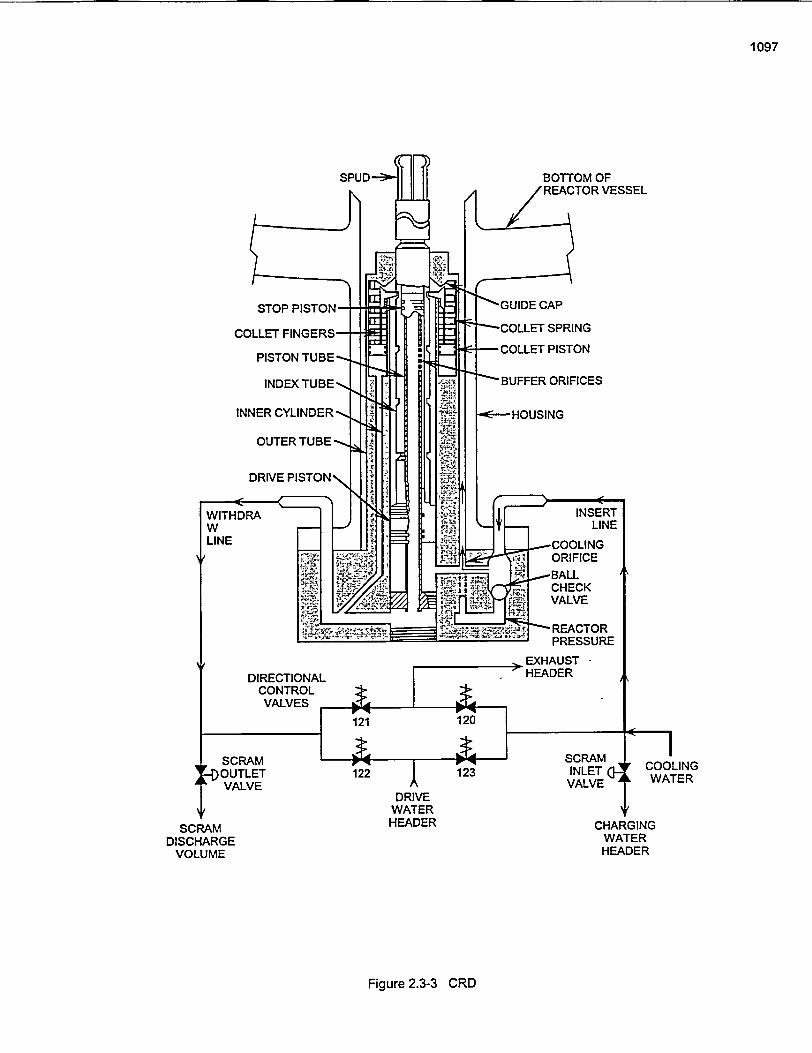
1097
OUTLET 122 123 INLET COOLING
VALVE IVALVE WATERDRIVE
WATERSCRAM HEADER CHARGING
DISCHARGE WATERVOLUME HEADER
Figure 2.3-3 CRD
General Electric Technology Manual Recirculation SystemGeneral Electric Technology Manual Recirculation System
Table of Contents
2.4 RECIRCULATION SYSTEM ................................................. 1
2.4.1 System Description .............2.4.2 Component Description .........
2.4.2.1 Suction Valves ............2.4.2.2 Recirculation Pumps .......2.4.2.3 Discharge Valves ..........2.4.2.4 Jet Pumps ................
2.4.3 System Features ...............2.4.3.1 System Operation ..........
2.4.4 System Interfaces .............2.4.4.1 Reactor Vessel System ......2.4.4.2 Recirculation Flow Control ...2.4.4.3 Residual Heat Removal System2.4.4.4 Reactor Water Cleanup System2.4.4.5 Neutron Monitoring System . .2.4.4.6 Control Rod Drive System ...
2.4.5 Summary .....................
......
..... .
......
......
......
..... .
......
......
......
......
......
.....
......
......
......
...............
...............
...............
...............
...............
...............
...............
...............
...............
...............
...............
...............
...............
...............
...............
...... .
.......
...... .
...... .
...... .
...... .
...... .
..... ..
...... .
...... .
.......
.......
...... .
...... .
........
........
........
........
.... ....
..... ...
........
........
........
........
........
........
..... ...
........
....
....
....
....
....
....
....
....
....
....
....
....
1111222233333333
List of Figures
Figure 2.4-1Figure 2.4-2
.................................................. Recirculation System................................................... Shaft Seal Assembly
USNRC Technical Training Center 2.4.1 Rev 0100USNRC Technical Training Center 2.4-i Rev 0100
General Electric Technoloev Manual - - - -, ' Recirculation Systemen-- Eet _ Manua _ _ _ Recrca___S
2.4 RECIRCULATION SYSTEM
The purpose of the Recirculation System is Iprovide forced circulation of water through ttreactor core, permitting higher reactor power thawith natural circulation.
The functional'classification of the RecirculaticSystem is that of a power generation system.
2.4.1 System Description I ;'
The Recirculation System provides the drivinforce to circulate coolant through the reactor corThe system consists of two piping loops extern;to the reactor vessel and 20 jet pumps which alinternal to the reactor vessel. Each loop has
- suction-isolation valve, a recirculation pump,'discharge isolation valve, instrumentation, anpiping connecting to the reactor vessel. T1
' Recirculation System is shown in Figure 2.4-1.
- Th6 variable speed recirculation pumps'. tal- suction from the reactor vessel annulus region an
provide flow to the jet pump riser pipes througthe reactor vessel shell. Internal piping directs tl
- ~'driving flow to'the jet pumps. The jet pumiinduce additional water from the reactor vessi
qfianulus region into the flowpath and force it i-- 'flow through the core.
the recirculation pump for maintenance. There areno automatic closure conditions associated with
:t these valves.le -
in ~2.4.2.2 Recirculation Pumps
There is a recirculation pump in each recirculationin loop between the suction and discharge valves.
These pumps are vertical, single stage, centrifugalpumps driven by variable speed electric motors.The pumps provide the driving flow to' the jetpumps and have a rated flow of 45,200 gallons per
Lg - minute each. The speed of the -recirculation'e. pumps, 'and hence -the system flowrate, is
al controlled by the Recirculation Flow Controlre -System ( Section 7.2).-
a - Each recirculation pump is equipped with a shaftid seal assembly, shown in Figure 2.4-2, to preventle leakage of recirculation water, along the shaft
which connects the recirculation pump motor tothe recirculation pump. The shaft -seal assembly
:e consists f of ,two individual, 100% capacity,id- 'mechanical -seals built into a- single cartridge.;h' Although each seal can individually seal againstle 'full primary system pressure, the normal pressure)s drop across each seal is about half of that value, or-l 500 psid. This pressure differential is provided byto the control pressure breakdown orifices. In the
event that either seal should fail, the remaining- ' .. seal can withstandthe full pressure drop from
2.4.2 Component Description rated system pressure to atmospheric and stillTh - ' - i > .maintain seal integrity. In the event that both seals
'-The major components of the Recirculation should fail, there is a breakdown bushing in the'System are discussed in the paragraphs which recirculation pump casing to limit water leakagefollow. '' along the shaft to a nominal value of 60 gallons
per minute.2.4.2.1 Suction Valves
t - ~ 'Provisions are made for monitoring the pressureThere is a suction valve in each recirculation loop drop across 'each individual seal as well as the
---betw'een the-reactor-vessel'penetration"and the controlled seal leakage flow. Various controlrecirculation pump. 'These -suction valves are -. room alarms indicate improper seal performance.motor operated isolation valves which are- * ; .normally open but which can be closed to isolate'
- I USNRC Technical Training Center USNRC Technical Training Center §2.4-1 - Rev 11100.e2.4-1 -. Rev 0100
General Electric Technology Manual Recirculation SystemGeneral Electric Technology Manual Recirculation System
Seal purge water, supplied from the Control RodDrive System (Section 2.3), keeps therecirculation pump seals clean and cool.Approximately 3 gpm of cool, filtered water isinjected between the number one seal and thebreakdown bushing. The seal purge substantiallyreduces the possibility of the seals being damagedby dirt from water supplied by the recirculationpump water.
2.4.2.3 Discharge Valves
Each recirculation loop contains a motor operateddischarge valve located between the recirculationpump and the loop flow measurement device. Thevalve is remotely operated from the control roomusing an open/close control switch. The dischargevalve is sealed-in to close and throttle to open.The discharge valves are automatically joggedopen on a pump startup by the Recirculation FlowControl System (Section 7.2). Additionally,discharge valves close as part of the automaticinitiation sequence for the low pressure coolantinjection (LPCI) mode of the'Residual HeatRemoval'(RHR) System (Section 10.4) to providean emergency core cooling water flowpath to thereactor vessel.
2.4.2.4 Jet Pumps
There is a bank of 10 jet pumps associated witheach of the external recirculation loops. All jetpumps are located in the reactor vessel annulusregion between the inner vessel wall and the coreshroud. Thejet pumps are provided to increase thetotal core flow while minimizing the flow externalto the reactor vessel (recirculation loop flows).
Each jet pump has a converging nozzle throughwhich the driving flow passes. This creates a highvelocity and relatively low' pressure condition atthe jet pump suction; This lowv pressure conditioncreates additional flow from the vessel annulus,called induced flow, through the jet pump. The
combined driving flow and induced flow mix inthe mixer section of the jet pump and then passthrough the diffuser section. The diffuser sectionincreases the flow area which decreases fluidvelocity and increases pressure. During full poweroperation approximately one-third of the total coreflow comes from the discharge of the recirculationpumps while the remaining two-thirds is inducedby the jet pumps.
2.4.3 System Features
A short discussion of system features is given inthe paragraphs which follow.
2.4.3.1 System Operation
The recirculation pumps are started prior tocontrol rod withdrawal for a plant startup and areboth run at the same speed during power operationof the reactor. Should one recirculation loopbecome inoperable, plant operation may continuefor a specified time as limited by the plantTechnical Specifications. This is known as singlerecirculation loop operation. .1
Should both recirculation loops , becomeinoperable, plant operation may continue foranother specified time period if permitted by theplant Technical Specifications. This is a conditionknown as natural circulation. Even though there isnot external recirculation loop drive- flow,, therestill is natural circulation flow through the jetpump suctions. The natural circulationphenomenon occurs within the reactor vesselbecause of coolant density differences betweenthe reactor core region and the vessel annulus.
2.4.4 System Interfaces
The interfaces this system has with other plantsystems are discussed in the paragraphs whichfollow.
USNRC Technical Training Center 2.4-2 Rev 0100USNRC Technical Training Center 2.4-2 Rev 0100
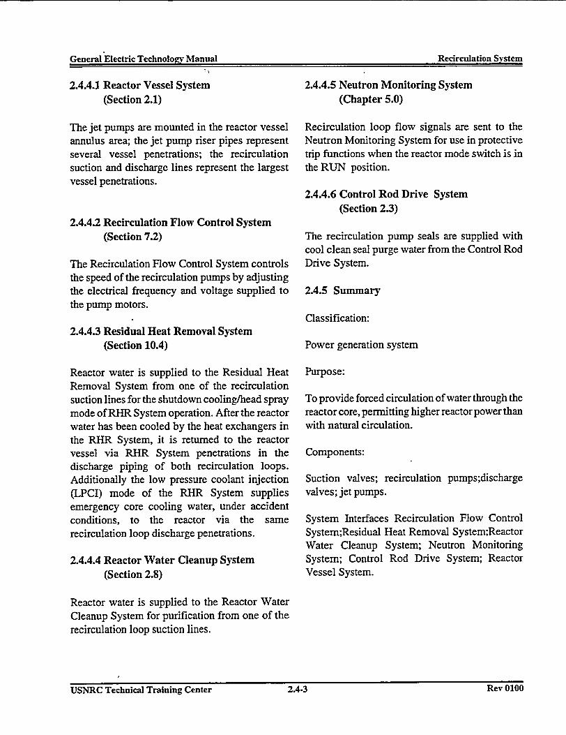
General .Electric Technolopv Manual Recirculation SystemGeneral Electric Technolo�v Manual Recirculation System
2.4.4.1 Reactor Vessel System(Section 2.1)
The jet pumps are mounted in the reactor vesselannulus area; the jet pump riser pipes representseveral vessel penetrations; the recirculationsuction and discharge lines represent the largestvessel penetrations.
2.4.4.2 Recirculation Flow Control System(Section 7.2)
The Recirculation Flow Control System controlsthe speed of the recirculation pumps by adjustingthe electrical frequency and voltage supplied tothe pump motors.
2.4.4.3 Residual Heat Removal System(Section 10.4)
Reactor water is supplied to the Residual HeatRemoval System from one of the recirculationsuction lines for the shutdown cooling/head spraymode of RHR System operation. After the reactorwater has been cooled by the heat exchangers inthe RHR System, it is returned to the reactorvessel via RHR System penetrations in thedischarge piping of both recirculation loops.Additionally the low pressure coolant injection(LPCI) mode of the RHR System suppliesemergency core cooling water, under accidentconditions, to the reactor via the samerecirculation loop discharge penetrations.
2.4.4.4 Reactor Water Cleanup System(Section 2.8)
2.4.4.5 Neutron Monitoring System(Chapter 5.0)
Recirculation loop flow signals are sent to theNeutron Monitoring System for use in protectivetrip functions when the reactor mode switch is inthe RUN position.
2.4.4.6 Control Rod Drive System(Section 2.3)
The recirculation pump seals are supplied withcool clean seal purge water from the Control RodDrive System.
2.4.5 Summary
Classification:
Power generation system
Purpose:
To provide forced circulation of water through thereactor core, permitting higher reactor power thanwith natural circulation.
Components:
Suction valves; recirculation pumps;dischargevalves; jet pumps.
System Interfaces Recirculation Flow ControlSystem;Residual Heat Removal System;ReactorWater Cleanup System; Neutron MonitoringSystem; Control Rod Drive System; ReactorVessel System.
Reactor water is supplied to the Reactor WaterCleanup System for purification from one of therecirculation loop suction lines.
USNRC Technical Training Center 2.4.3 Rev 0100USNRC Technical Training Center 2.4-3 Rev 0100
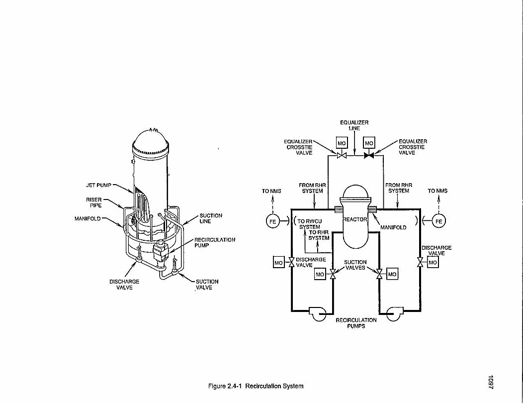
EQUALIZER
JET PUMP
RISER -PIPE
MANIFOLD -
DISCHARGE "- SUCTIONVALVE VALVE
RECIRCULATIONPUMPS
-ACD-J0Figure 2.4-1 Recirculation System
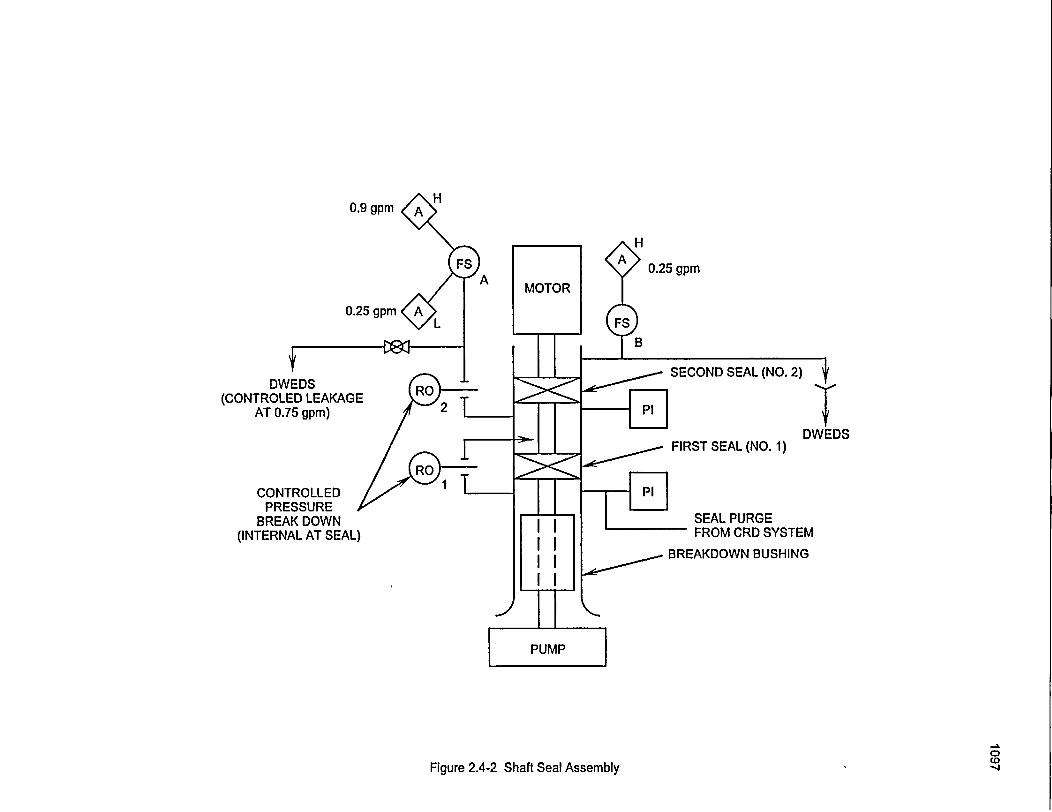
0.9 gpm
H
0.25 gpm
0.25 gpm
SECOND SEAL (NO. 2)DWEDS
(CONTROLED LEAKAGEAT 0.75 gpm) 4'
DWEDSFIRST SEAL (NO. 1)
CONTROLLEDPRESSURE
BREAK DOWN(INTERNAL AT SEAL)
SEAL PURGEFROM CRD SYSTEM
BREAKDOWN BUSHING
0to
Figure 2.4-2 Shaft Seal Assembly
General Electric Technology Manual Main Steam System
Table of Contents
2.5 MAIN STEAM SYSTEM ................................................... 1
2.5.1 System Description..12.5.2 Component Description .. 1
2.5.2.1 Safety/Relief Valves ............................................... 12.5.2.2 Main Steam Line Flow Restrictors ............................ . 2
2.5.2. Main Steam Isolation Valves ............................. . 22.5.2.4 Main Steam Line Drains ............................. . 22.5.2.5 Bypass Valves .............................. . 22.5.2.6 Turbine Stop Valves ............................................... 22.5.2.7 Turbine Control Valves ............................. . 22.5.2.8 Turbine .............................. . 22.5.2.9 Other Steam Equipment ............................. . 32.5.2.10 Steam Jet Air Ejector (SJAE) ...................................... 3
2.5.3 System Features ................................................ 32.5.3.1 Main Steam Isolation Valves ............................. . 32.5.3.2 Turbine Stop and Control Valve Closure ............................ . 4
2.5.4 System Interfaces . ............................................... 42.5.4.1 Reactor Vessel System ............................. . 42.5.4.2 Condensate and Feedwater System ............................. . 42.5.4.3 Reactor Core Isolation Cooling System ............................ . 42.5.4.4 High Pressure Coolant Injection System ............................ . 42.5.4.5 Electro Hydraulic Control System ............................. . 42.5.4.6 Feedwater Control System ............................. . 42.5.4.7 Primary Containment IsolationSystem ............................ . 52.5.4.8 Reactor Protection System .......................................... . 52.5.4.9 Offgas System .............................. .52.5.4.10 Liquid Radwaste System .......................................... 52.5.4.11 Automatic Depressurization System ................................. 5
2.5.5 Summary ............................................... 5
List of Figures
Figure 2.5-1 ............................ Main Steam System
USNRC Technical Training Center 2.5-i Rev 0100
1. General Electric Technoloav Manual ' Main Steam SvstemGeea Elcti TebooyMna anSemSse
2.5 -' MAIN STEAM SYSTEM 2.5.2.1 Safety/Relief Valves- (Figure 2.5-2)
The purposes of the Main Steam System are: - *- * The :Safety/Relief 'valves (11) provide
1. To direct steam from the reactor vessel to the overpressure protectioni for the reactor vessel andmain turbine and other steam loads. associated piping systems. In addition a selected
-. ' ' t;_number of safety/relief valve's are used by the'2. To provide overpressure protection for the - Automatic Depressurization System (Section*Reactor Coolant System. - 10.2). K - i' '
The funictional classification of the Main Steam All of the safety/relief 'valves are mounted 6n aSystem' is that of a power generation system. The,' horizontal portion of the main steam lines insidemain steam system does, however, contain three the drywell. They are dual actuating type valvescomponents which are-engineered safety features and discharge to the suppression pool. Actuation(ESF). These ESFs are the main steam isolation is accomplished by- either; '(1) -high systemvalves, the main steam line flow restrictors, and pressure (safety mode); (2) remotely by operatorthe safety/relief valves. action; (3) the ADS logic. . -
2.5.1 System Description ' In the safety mode, the safety/relief valves are, -, ''actuated by high pressure steam positioning a
'The flow path for the-Main Steam System is pilot valve against setpoint spring- pressure to"shownion Figure 2.5-1. Within the drywell, steam Z depressurize the top of the main valve piston. Theis transmitted from the reactor vessel to the -removal of steam on top of the main valve pistoninboard main steam isolation valves via 4 steam creates a differential pressure which forces thelines. Each of the lines contain safety/relief main valve open. Steam is released through thevalves, steam line flow restrictors, drain line valve to the suppression pool, lowering reactorconnection and inboard isolation -valves. Also pressure.provided from the steam lines is a reliable source"of steam for the High Pressure Coolant Injection' In the relief mode of operation, air pressure is-System and the R'eacior Core Isolation Cooling - -applied to an air actuator by energizing a solenoid
'System.- -' . operated valve. The-air actuator mechanically- positions the pilot valve, depressurizing the top of
Outside of the drywell, the steam progresses the main valve piston to cause the main valve tothrough outboard isolation valves to an equalizing open. The solenoids are energized by switchesheader where all 4 of the steam lines terminate. located in the control room. This type ofFrom the equalizing header steam is routed to the arrangement provides the control room operatormain turbine 'and a number of auxiliary support with a means to operate any of the 11 safety/reliefsystems. - valves. Seven of the safety/relief valve solenoids
can also, be energized -by, actuation . of the' 2.5.2 CvComponent Description n - .. Automatic Depressurization System logic .
, ''a *' r f - I ' ,, ,. -. *|Q
The major components of the Main Steam System ' - - .are discussed in the paragraphs which follow. - - -
USNRC Technical Training Center 2.5-1 . - Rev 0100
General Electric Technology Manual Main Steam SystemGeneral Electric Technolo�v Manual Main Steam System
2.5.2.2 Main Steam Line Flow Restrictors
The main steam line flow restrictor is aengineered safety feature incorporated into theplant design to limit the loss of mass inventoryfrom the reactor during a steam line break. Eachflow restrictor is designed to limit steam flow toless than 200% of rated steam flow during a steamline break. The flow restrictors are also used todevelop steam flow signals for use in theFeedwater Control System (Section 3.3) 'andPrimary Containment Isolation System (Section4.4).
2.5.2. Main Steam Isolation Valves
The Main Steam Isolation Valves (MSIV's) areprovided to limit the release of radioactivematerials to the environment following a steamline break outside of containment. Redundantvalves are located on each main steam line, oneinside and one outside the primary containment.The MSIV's are air/spring operated valves; air toopen; air and/or spring to close.
controlled by the Electro Hydraulic ControlSystem (Section 3.2).
2.5.2.6 Turbine Stop Valves
There are four turbine stop valves located in themain steam piping just upstream of turbine controlvalves (Figure 2.5-1). The stop valves arenormally open during turbine operation with arapid closure capability upon detection ofpotentially unsafe turbine conditions. The numbertwo stop valve also contains an internal bypasswhich is used to equalize pressure across the stopvalves prior to opening.
2.5.2.7 Turbine Control Valves
The control valves regulate the steam flow to theturbine, as controlled by the Electro HydraulicControl (EHC) System, in order to control reactorpressure. The control valves also provide thecontrol mechanism for rolling, synchronizing, andloading the turbine generator.
2.5.2.8 Turbine2.5.2.4 Main Steam Line Drains
The main steam line drains are provided to servea dual function. The first function is to removemoisture from the steam lines prior to and duringturbine operation. The removal of moisture helpsprevent damage to the turbine blades. The steamline drains also provides the capability to equalizepressure around the MSIVs prior to opening.
2.5.2.5 Bypass Valves
Four bypass valves are used to bypass up to 30%of rated steam flow directly to the condenser whenthe main turbine is not capable of using the steam.The bypass valves work in conjunction with theturbine control valves to ensure a constant reactorpressure for a given reactor power level.Operation of the bypass valves is automatically
The main turbine is an 1800 RPM,, tandemcompound machine, consisting of one highpressure turbine and three low pressure. turbines.The steam enters the middle of the high pressuresection and works its way toward each end,dissipating its energy to the turbine blades whichare attached to a common shaft. fSteam exiting the high pressure turbine passesthrough moisture separators where entrainedmoisture, which could cause turbine bladedamage, is removed prior to entering the lowpressure turbines.
Prior to entering the low pressure turbines,- thesteam passes through the low pressure turbinecontrol and stop valves which are called combinedintermediate valves (CIV's) and are actually twovalves in one housing. The intercept valves
' USNRC Technical Training Center 2.5-2 Rev 0100
:' - General Electric Technoloev Manual _ - I � IMain Steam SvstemGeneral Electric Technoloav Manual Main Steam Sirstem
provide thiottling to prevent turbine overspeedcaused by a rapid reduction in generator load. The'CIV stop valve is designed to be fully open orfully closed (open during normal operation) andprovides a rapid means of isolating the lowpressure turbines from their steam supply whennecessary.
At different stages on the low pressure turbine aretaps for extracting steam. This steam is used topreheat'the feedwater going back to the reactorvessel (Section 2.6). l -*
2.5.2.11 Gland Seal Steam
* The steam space along' the turbine shaft, betweenthe turbine's last stage and atmosphere is sealed inorder to maintain the vacuum 'in 'the maincondenser and to prevent contaminated steamfrom leaking to atmosphere. Sealing isaccomplished 'by means of labyrinth tyje' 'shaftpacking which provide-a' series of throttling thatlimit steam leakage along the rotating shaft to aminimum as it is throttled from the high pressurespace to the low pressure space. -
The exhaust of the low pressure turbine sections 'Air and sfeam,_p6ssibly radioactive, are removedis directed to the condenser, where it is condensed from the seals through a steam packing exhaustand deaerated, then collected in a hotwell to be system and discharged to the plant stack systempumped by the Condensate and Feedwater System via a short holdup line (primarily for N16 decay).to the reactor vessel.
2.5.2.9 Other Steam Equipment
The Main Steam System supplies steam tonumber of components within the plant. Below isa listing of some of those components anddescription of those not covered elsewhere in this
.manual .
1. Steam Jet Air Ejector (SJAE)2. Gland Seal System3. Off Gas System (Section 8.1)4. Reactor Feed Pump Turbines (Section 3.3)5. Reactor Core Isolation Cooling System
(Section 2.7)6. High Pressure Coolant Injection System
(Section 10. 1)
2.5.2.10 Steam Jet Air Ejector (SJAE)
The Steam Jet Air Ejectors removenoncondensible gases from the condenser -an(
provide the motive force for moving these'gase:through the Offgas System'.
2.5.3 System Features
'A short discussion of system features is given inthe paragraphs which follow.
2.5.3.1 Main Steam Isolation Valves .'
To minimize the release of radioactive materialsto the environment the MSIV's receive automatic
"-closure signals from the -Primary. ContainmentIsolation System (Section 4.4). Automatic closureof all eight MSIV's is initiated under any of thefollowing conditions: r -
1. Low-Low. Reactor Vessel Water Level2. High Main Steam Line Radiation3. High Main Steam Line FlowA., High Steam Line Area Temperature5. Low Steam Line Pressure with the mode
switch in Run.
MSIV closure, with the reactor critical, can resultin a severe pressure and power increase. Becauseof this, MSIV closure signals the ReactorProtection System (Section 7.3) to scram thereactor. The valves are required to close in >3 but
I ',USNRC Technical Training Center k 2.5-3 - IS- T T C . Rev 0100
General Electric Technology Manual Main Steam SystemGeneral Electric Technology Manual Main Steam System
<5 seconds to minimize -the pressure/powerincrease and at the same time limit the release ofradioactive material on a downstream line break.
2.5.3.2 Turbine Stop and Control ValveClosure
The- hydraulically operated turbine stop andcontrol valves can be tripped closed within 0.1and 0.2 seconds respectively. Because of the largepressure and neutron flux spikes created by stopvalve closure and control valve fast closure, thereactor is automatically scrammed and reactorrecirculation pumps tripped if either conditionoccurs with power above the capacity of thebypass valves. -
2.5.4 System Interfaces
The interfaces this system has with other plantsystems are discussed in the paragraphs whichfollow.
2.5.4.1 Reactor Vessel System(Section 2.1)
The Main Steam System delivers steam from thereactor vessel to the various steam loads, ventsnoncondensible gases from the reactor vessel headarea, and provides overpressure protection for thereactor vessel.
2.5.4.2 Condensate and Feedwater System(Section 2.6)
The Condensate and Feedwater System usessteami from the equalizing header or the moistureseparators to drive the reactor feedpump turbinesand extraction steam from the main turbine to heatthe feedwater.
2.5.4.3 Reactor Core Isolation CoolingSystem (Section 2.7)
The Reactor Core Isolation Cooling System usessteam from the A steam line as the driving forcefor it's turbine.
2.5.4.4 High Pressure Coolant InjectionSystem (SectionlO.1)
The High Pressure Coolant Injection System usessteam from the B steam line as the driving forcefor its turbine.
2.5.4.5 Electro Hydraulic Control System(Section 3.2)
The Electro Hydraulic Control System controlsthe operation of the bypass valves and turbinesvalves to control reactor pressure and turbinegenerator load.
2.5.4.6 Feedwater Control System(Section 3.3)
The Feedwater Control System uses steam flowsignals from the steam line flow restrictors taps aspart of the three element level control network andfor indication.
2.5.4.7 Primary Containment IsolationSystem(Section 4.4)
The Primary Containment Isolation Systemisolates the Main Steam System when required.
2.5.4.8 Reactor Protection System(Section 7.3)
The Reactor Protection System uses MSIV andturbine stop valve position and turbine controlvalve fast closure signals to initiate reactorscrams.
USNRC Technical Training Center 2.5-4 Rev 0100USNRC Technical Training Center 2.5w4 Rev 0100
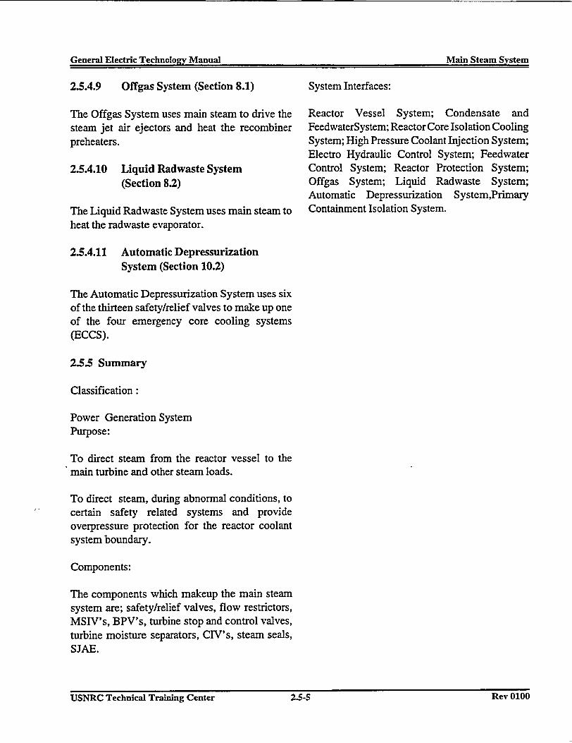
General Electric Technology Manual Main Steam Systemr E r .
2.5.4.9 Offgas System (Section 8.1)
The Offgas System uses main steam to drive thesteam jet air ejectors and heat the recombinerpreheaters.
2.5.4.10 Liquid Radwaste System(Section 8.2)
The Liquid Radwaste System uses main steam toheat the radwaste evaporator.
System Interfaces:
Reactor Vessel System; Condensate andFeedwaterSystem; Reactor Core Isolation CoolingSystem; High Pressure Coolant Injection System;Electro Hydraulic Control System; FeedwaterControl System; Reactor Protection System;Offgas System; Liquid Radwaste System;Automatic Depressurization System,PrimaryContainment Isolation System.
2.5.4.11 Automatic DepressurizationSystem (Section 10.2)
The Automatic Depressurization System uses sixof the thirteen safety/relief valves to make up oneof the four emergency core cooling systems(ECCS).
2.5.5 Summary
Classification:
Power Generation SystemPurpose:
To direct steam from the reactor vessel to themain turbine and other steam loads.
To direct steam, during abnormal conditions, tocertain safety related systems and provideoverpressure protection for the reactor coolantsystem boundary.
Components:
The components which makeup the main steamsystem are; safety/relief valves, flow restrictors,MSIV's, BPV's, turbine stop and control valves,turbine moisture separators, CIV's, steam seals,SJAE.
USNRC Technical Training Center 2.5-5 Rev 0100USNRC Technical Training Center 2.5-5 Rey 0100
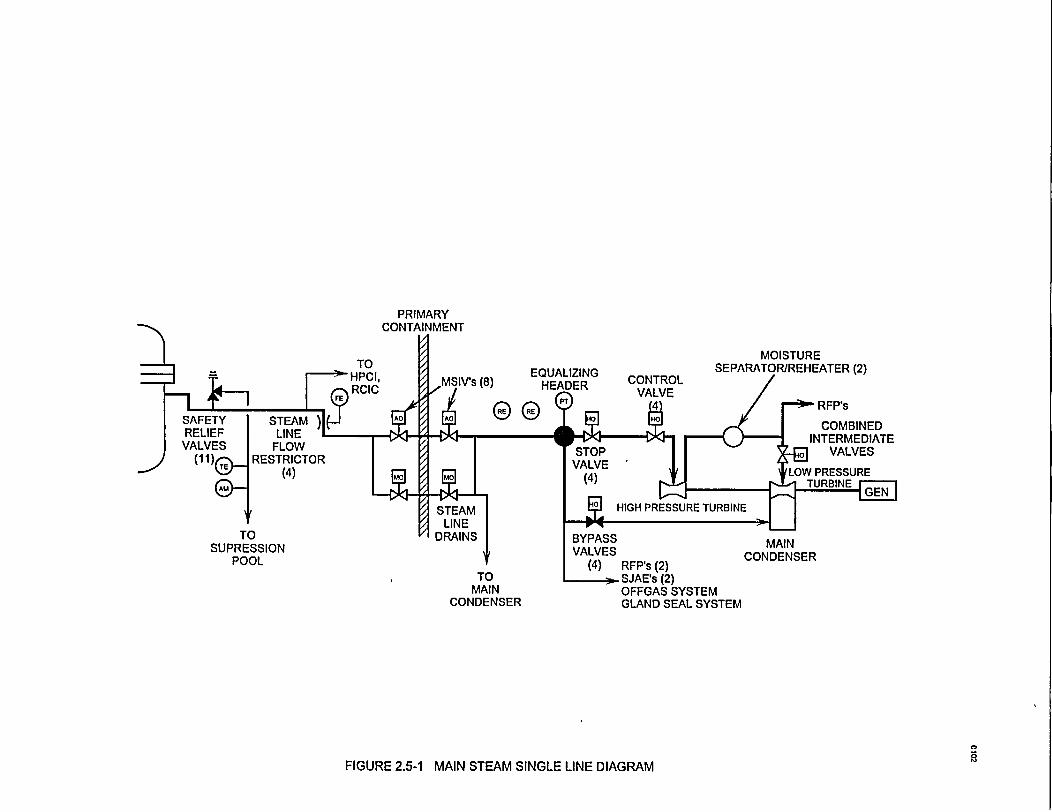
PRIMARY
MOISTURE
EQUALIZING(8) HEADER
(2)
RFP'sSAFETY STERELIEF LIDVALVES FL(
(1 1) RESTF
TOSUPRESSION
POOL
EAM )4IE L.OW,ICTORq4
MAINCONDENSER
TOMAIN
CONDENSER
FIGURE 2.5-1 MAIN STEAM SINGLE LINE DIAGRAM
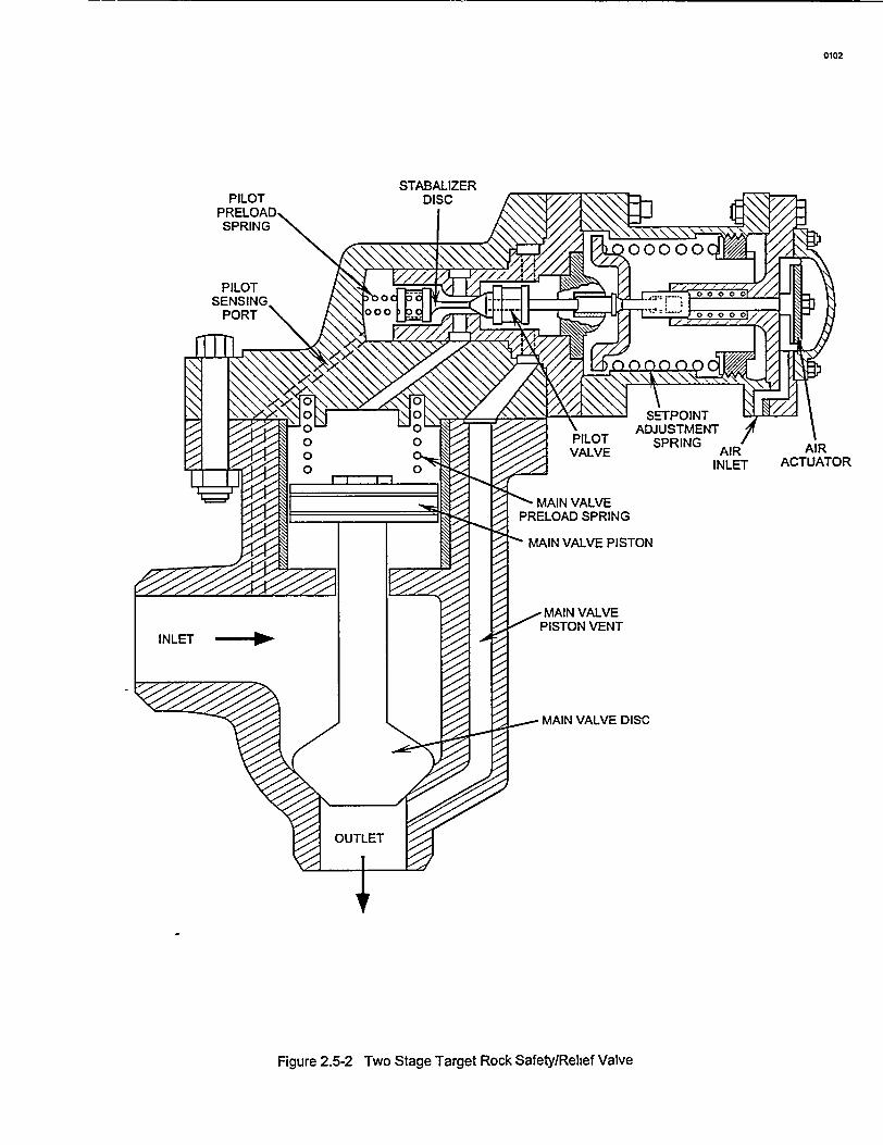
0102
PILOTPRELOAD,SPRING
PILOTSENSING-
N ! N SETPOINTADJUSTMENT
PILOT SPRINGVALVE AIR AIR
INLET ACTUATOR
- MAIN VALVEPRELOAD SPRING
' MAIN VALVE PISTON
-MAIN VALVEPISTON VENT
- MAIN VALVE DISC
Figure 2.5-2 Two Stage Target Rock Safety/Relief Valve
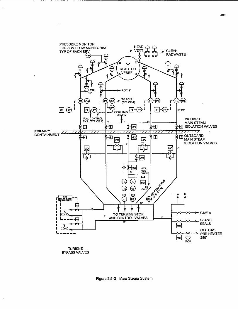
0102
PRIMARYCONTAINMENT
TO TURBINE STOPAND CONTROL VALVES
Is,
GASHEATER
TURBINEBYPASS VALVES
Figure 2.5-3 Main Steam System
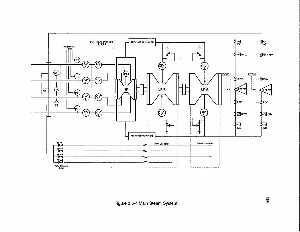
First Stage Pressureto RPS
i HPsV
Pr~
37B
25% CapacityTotal
to
Figure 2.5-4 Main Steam System
General Electric Technology Manual Condensate & Feedwater System
Table of Contents
2.6 CONDENSATE AND FEEDWATER SYSTEM .................................. 1
2.6.1 System Description .................................................... 12.6.2 Component Description ................................................ 1
2.6.2.1 Main Condenser ................................ . 12.6.2.2 Condensate Pumps ............................................... 12.6.2.3 Auxiliary Condensers ................................ . 22.6.2.4 Condensate Filter IDemineralizers ................... . 22.6.2.5 Condensate Booster Pumps. : 22.6.2.6 Low Pressure Feedwater Heaters.. 22.6.2.7 Reactor Feedwater Pumps ............................................ 32.6.2.8 High Pressure Feedwater Heaters ................... . 32.6.2.9 Feedwater Spargers ............................................. 3
2.6.3 System Features ................ ...................................... 32.6.3.1 Startup Operation .............................................. 32.6.3.2 Normal Operation .......................................... ... 4
2.6.4 System Interfaces ......................... .................... 42.6.4.1 Feedwater Control System ........................................... 42.6.4.2 Reactor Water Cleanup System ................... . 42.6.4.3 Reactor Core Isolation CoolingSystem .................. . 42.6.4.4 Main Steam System ............................................. 42.6.4.5 Offgas System .............................................. 42.6.4.6 .............................................. 4
2.6.5 Summary ............................................. 4
List of Figures
Figure 2.6.1 .. . . Condensate and Feedwater SystemFigure 2.6.2 .. .. Condensate and Feedwater System (detail)
USNRC Technical Training Center 2.6-i Rev 0100
-'General Electric Technology Manual I -Condensate&-FeedwaterSystem:GnrlEeti ecnogy Ma ICnest &FewtrSse
2.6 CONDENSATE AND FEEDWATER-r SYSTEM
The purposes of the Condensate and FeedwaterSystem are: - *
I'.--'To condense steam and collect drains in'the main condenser.
- 2. To purify, preheat, and pump water from' -' the main condenser to the reactor vessel.
'The functional 'classification of the Condensateanid Feedwater System is that of a-'powergeneration system.
2.6.1 System Description
The Condensate and Feedwater System, shown inFigure 2.6-1, is an integral part of the'plant'sconventional regenerative steam cycle. The steamexhausted from theTthree low pressure turbines iscon'densed iri the main condenser and collected inthe condenser hotwell, along with variousequipment drains. The condensate that is collectedin the hotwell is removed by three condensatepumps. The condensate pumps provide the drivingforce for the condensate which flows through the
feedwater heater strings 'for the final stage offeedwater heating. Two feedwater lines penetratethe primary containment and then further divideinto a 'total of six penetrations which enter thereactor vessel with each supplying feedwater to afeedwater; sparger.' The feedwater . spargersdistribute the flow of feedwater within the vesselannulus area.
2.6.2 Component Description -.
-~ i , '
The components that comprise the Condensateand Feedwater System are discussed in thefollowing paragraphs and illustrated in Figure 2.6-
I. . -
2.6.2.1 Main Condenser
- The main condenser is a surface condenser withthree separate shells with each shell operating atthe same vacuum. The condensers serve as themain heat sink for low pressure turbine exhaust'and several other flows, such as exhaust steamfrom the reactor feed pump turbines,-cascadinglow pressure heater drains, SJAE drains, turbinebypass valves, etc. The condenser also provides anarea for noncondensible gases fromr'the primarysteam to be collected and exhausted via the
steam jet air ejector (SJAB) condensers, steam ' SJAE's. -
packing exhaust condenser, and offgas condenser'performing a heat removal function. At this point The, condensed steam and various -drains
- the condensate is directed to the condensate filter/ -, accumulate in the bottom of the condenser in andemineralizers and, through the process ofs 'area termed-the -hotwell andy-are designatedfiltration; and ion exchange; impurities "are - -condensate water: - -
removed. After the demineralizers, booster pumpsare used to maintain the driving force 'of the 2.6.2.2 Condensate Pumps
- condensate flow through-strings of low pressure - £ -.- ifeedwiterheaters.'Thefeedwaterpumpsthentake Two motor driven condensate pumps, with a
the condensate flow and further increase 'the capacity of 50% each, remove water from thepressure to a value above reactor pressure. The main condenser hotwell and discharge to parallel
- amount of feedwater flowing to the reactor vessel string -of auxiliary condensers. The auxiliaryis controlled by varying the speed of the turbine condensers consist of two Steam Jet Air Ejectordriven reactor feed pumps. The discharge of the - (SJAE) condensers, two offgas condensers, andfeedwater pumps is directed to the high pressure * one steam seal condenser. - - -
I.- USNRC Technical Training Center USNRC Technical Training Center - 2.6-1 Rev 0100- 2.6-1 Rev 0100
General Electric TechnoloLTv Manual I Condensate & Feedwater SvstemGeneral Electric Tecbnoloav Manual Condensate & Feedwater System
2.6.2.3 Auxiliary Condensers
The auxiliary condensers are shell and tube typeheat exchangers with condensate passing throughthe tubes condensing steam outside the tubes. Theauxiliary condensers Perform a dual function bycondensing the steam and adding heat to thecondensate system.
The Steam Jet Air Ejector (SJAE) condensers areused to condense the steam exhausted from thefirst stage SJAE (Section 8.1).
The purpose of the steam seal condenser is tocondense the leak off from the main and reactorfeed pump turbine seals. A vacuum is maintainedin the condenser by one of two blowers whichremove noncondensible gases and dischargethrough a 1.75 minute holdup to the plant stack(Section 8. 1).
The offgas condenser removes excessive moisturefrom the offgas process mixture following therecombination of hydrogen and oxygen in theoffgas system (Section 8.1).
2.6.2.4 Condensate Filter/Demineralizers
The purpose of the condensatefilter/demineralizers is to treat the full flow ofcondensate from the condenser- hotwell. byremoving impurities through filtration and ionexchange. Impurities consist of but are not limitedto corrosion products and any circulating water inleakage to the condenser.The condensate filter/demineralizers consist ofnine filter/demineralizer units located inindividual concrete cells and a common backwashand precoat system.
Each filter/demineralizer unit consists ofa verticalcylindrical vessel which houses several nylonfilter elements. The filter elements are coated witha mixture of powdered cation and anion exchange
resins in hydrogen and hydroxyl forms. Thecoating is applied to the elements to a thickness ofabout 0.25 inches.
When a filter/demineralizer unit exceeds aspecified differential pressure or when the effluentconductivity increases above lymho/cm the unitis removed from service. With the unit out ofservice, the spent resin is removed by reversingthe normal flow path (backwashing) and sent tothe Solid Radwaste System for disposal. A freshresin slurry is then applied by the precoat systemand the unit is placed back in service or standbyuntil needed. The entire backwashing and precoatoperation for a single unit requires about onehour.
2.6.2.5 Condensate Booster Pumps
Two, 50% capacity condensate booster pumpstake suction on the filter/demineralizers outletheader and discharge to the low pressurefeedwater heaters. The condensate booster pumpsare motor driven with a discharge pressure of 600psig.
2.6.2.6 Low Pressure Feedwater Heaters
The low pressure feedwater heaters are arrangedin three parallel strings with each string consistingof one drain cooler and three low pressure heaters.The low pressure feedwater heaters utilizeextraction steam from the three low pressureturbines to heat the feedwater prior to returning itto the reactor vessel thus increasing plantefficiency. The heaters are constructed so thatcondensate flows through the heater tubes whileextraction steam flows around the tubes. Thecondensed extraction steam (extraction drains)from each heater flows to the next lower pressureheater by means of the pressure differencebetween the successive heaters.
USNRC Technical Training Center 2.6-2 Rev 0100USNRC Technical Training Center 2.6.2 Rev 0100
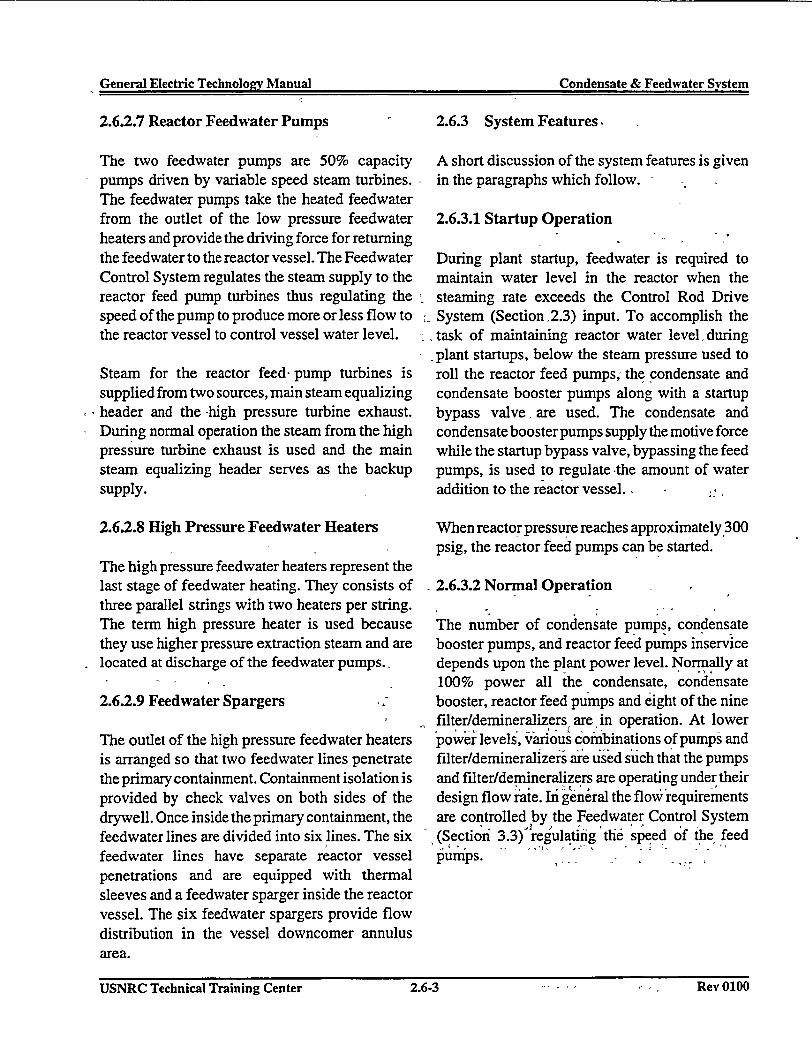
General Electric Technolozv Manual Condensate & Feedwater SvstemGeneral Electric Technolo2v Manual Condensate & Feedwater System
2.6.2.7 Reactor Feedwater Pumps
The two feedwater pumps are 50% capacitypumps driven by variable speed steam turbines.The feedwater pumps take the heated feedwaterfrom the outlet of the low pressure feedwaterheaters and provide the driving force for returningthe feedwater to the reactor vessel. The FeedwaterControl System regulates the steam supply to thereactor feed pump turbines thus regulating thespeed of the pump to produce more or less flow tothe reactor vessel to control vessel water level.
Steam for the reactor feed pump turbines issupplied from two sources, main steam equalizingheader and the -high pressure turbine exhaust.During normal operation the steam from the highpressure turbine exhaust is used and the mainsteam equalizing header serves as the backupsupply.
2.6.2.8 High Pressure Feedwater Heaters
The high pressure feedwater heaters represent thelast stage of feedwater heating. They consists ofthree parallel strings with two heaters per string.The term high pressure heater is used becausethey use higher pressure extraction steam and arelocated at discharge of the feedwater pumps.
2.6.2.9 Feedwater Spargers
The outlet of the high pressure feedwater heatersis arranged so that two feedwater lines penetratethe primary containment. Containment isolation isprovided by check valves on both sides of thedrywell. Once inside the primary containment, thefeedwater lines are divided into six lines. The sixfeedwater lines have separate reactor vesselpenetrations and are equipped with thermalsleeves and a feedwater sparger inside the reactorvessel. The six feedwater spargers provide flowdistribution in the vessel downcomer annulusarea.
2.6.3 System Features,
A short discussion of the system features is givenin the paragraphs which follow.
2.6.3.1 Startup Operation
During plant startup, feedwater is required tomaintain water level in the reactor when thesteaming rate exceeds the Control Rod DriveSystem (Section.2.3) input. To accomplish thetask of maintaining reactor water levelduringplant startups, below the steam pressure used toroll the reactor feed pumps; the condensate andcondensate booster pumps along with a startupbypass valve, are used. The condensate andcondensate booster pumps supply the motive forcewhile the startup bypass valve, bypassing the feedpumps, is used to regulate -the amount of wateraddition to the reactor vessel.-
When reactorpressure reaches approximately 300psig, the reactor feed pumps can be started.
2.6.3.2 Normal Operation
The number of condensate pumps, condensatebooster pumps, and reactor feed pumps inservicedepends upon the plant power level. Normall at100% power all the condensate, condensatebooster, reactor feed pumps and eight of the ninefilter/demineralizers, are, in operation. At lowerpower levels, various combinations of pumps andfilter/demineralizers are used such that the pumpsand filter/demineralizers are operating under theirdesign flow rate. Ini general the flow requirermentsare controlled by the Feedwater Control System(Section 3.3) regulating the speed of the feedpumps. - ,
USNRC~~~~~~~~~ Tehial riigCne .-. Rv00USNRC Technical Training Center 2.6-3 Rev 0100
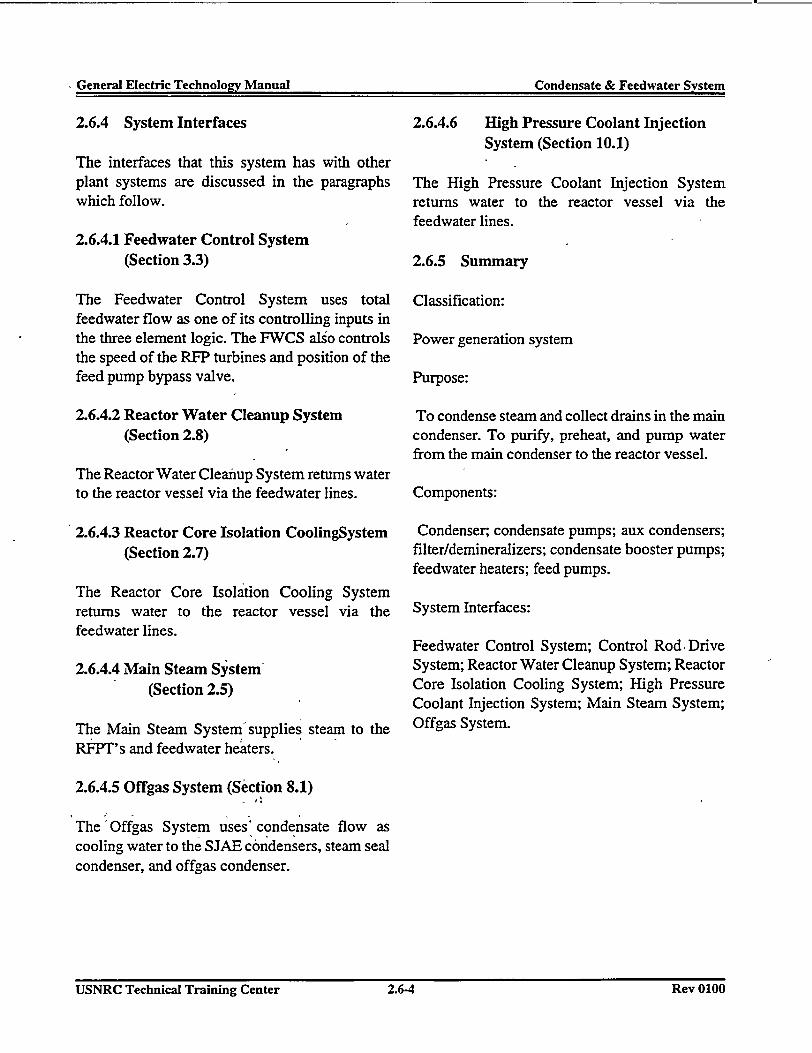
IGeneral Electric Technology Manual Condensate & Feedwater System-General Electric Technology Manual Condensate & Feedwater System
2.6.4 System Interfaces
The interfaces that this system has with otherplant systems are discussed in the paragraphswhich follow.
2.6.4.1 Feedwater Control System(Section 3.3)
The Feedwater Control System uses totalfeedwater flow as one of its controlling inputs inthe three element logic. The FWCS also controlsthe speed of the RFP turbines and position of thefeed pump bypass valve.
2.6.4.2 Reactor Water Cleanup System(Section 2.8)
2.6.4.6 High Pressure Coolant InjectionSystem (Section 10.1)
The High Pressure Coolant Injection Systemreturns water to the reactor vessel via thefeedwater lines.
2.6.5 Summary
Classification:
Power generation system
Purpose:
To condense steam and collect drains in the maincondenser. To purify, preheat, and pump waterfrom the main condenser to the reactor vessel.
The Reactor Water Cleanup System returns waterto the reactor vessel via the feedwater lines.
2.6.4.3 Reactor Core Isolation CoolingSystem(Section 2.7)
The Reactor Core Isolation Cooling Systemreturns water to the reactor vessel via thefeedwater lines.
2.6.4.4 Main Steam System-(Section 2.5)
The Main Steam System supplies steam to theRFPT's and feedwater heaters.
Components:
Condenser; condensate pumps; aux condensers;filter/demineralizers; condensate booster pumps;feedwater heaters; feed pumps.
System Interfaces:
Feedwater Control System; Control Rod, DriveSystem; Reactor Water Cleanup System; ReactorCore Isolation Cooling System; High PressureCoolant Injection System; Main Steam System;Offgas System.
2.6.4.5 Offgas System (Section 8.1)
The Offgas System uses' condensate flow ascooling water to the SJAE condensers, steam sealcondenser, and offgas condenser.
USNRC Technical Training Center 2.6-4 Rev 0100USNRC Technical Training Center 2.6X4 Rev 0100
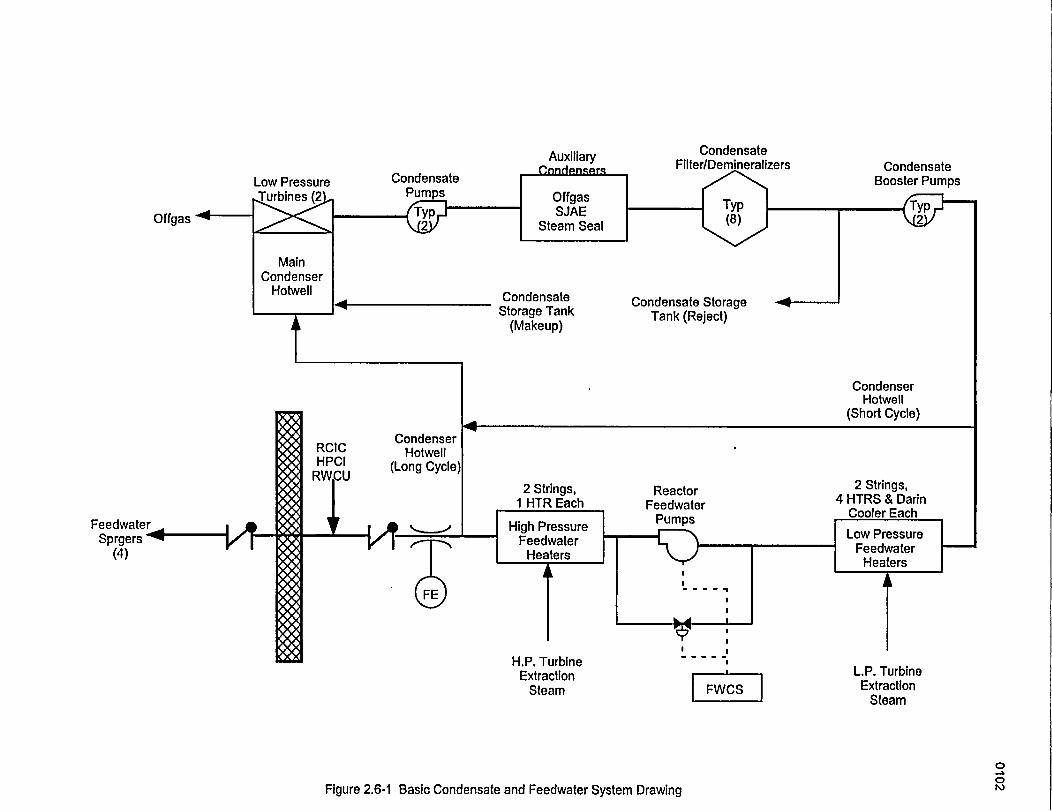
Auxiliary
Low Pressure Condensate
Offgas
CondensateFilter/Demineralizers Condensate
Booster Pumps
Typ](8) \2
Condensate StorageTank (Reject)
CondensateStorage Tank
(Makeup)
CondenserHotwell
(Short Cycle)
RCICHPCI
CondenserHotwell
ReactorFeedwater
DSnortFeewtrI ,8 High Pressure _ rumps o resr
Low PressureSprgers Feedwater
()Heaters Heaters
g lit
H.P. Turbine---IExtraction L.P. Turbine
Steam ExtractionSteam
Flimira 9 R..1 Rn~ir- Cnndgan~nfc ~nnd Paadjwnfar Que*fam nlr~~AnnI It,-,- - . --- I- -..- . -Y-."
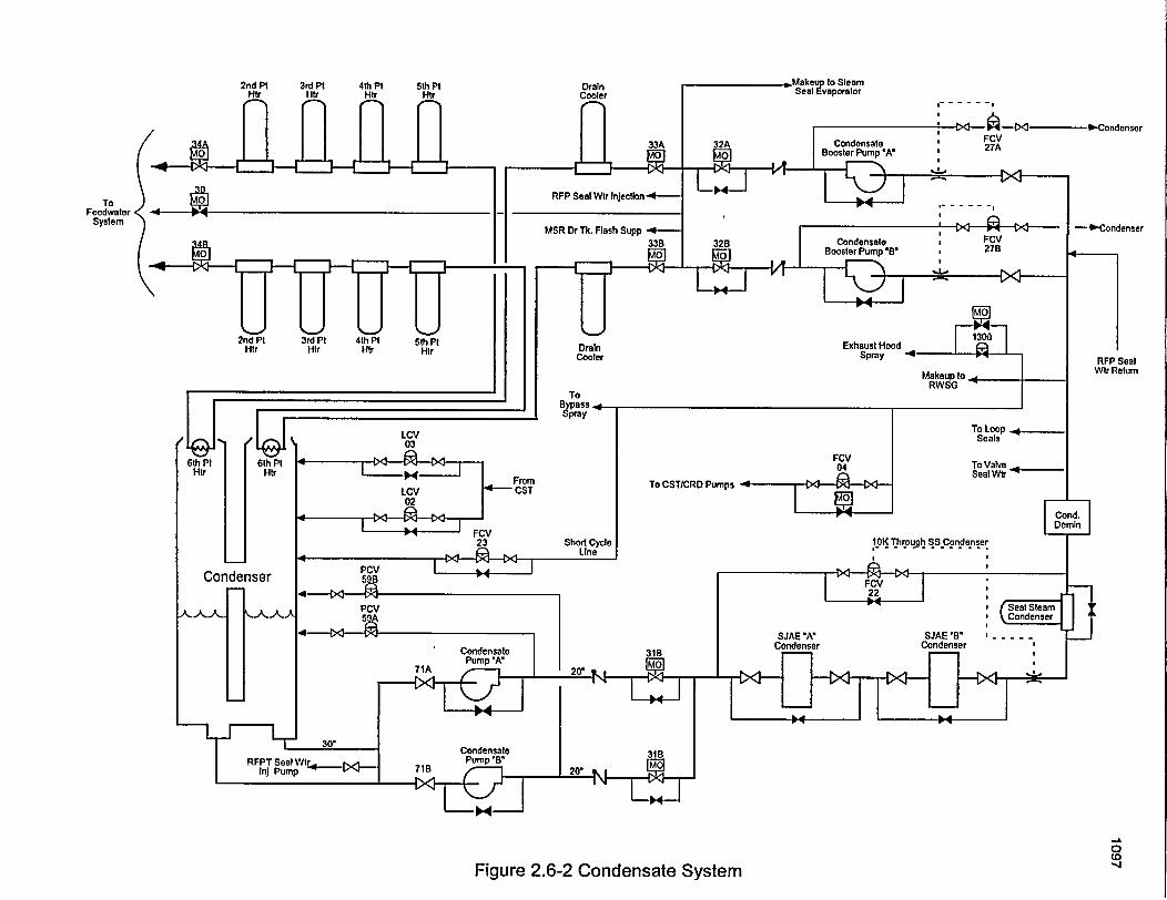
DrainCooler
I- - - - ,I
ToFeedwater
System-1-Condenser
DrainCooler RFP Seal
Wtr Return
To Loop .Seals
To ValveSeal Wtr'
To CST/CRD Pumps
10K Through SS Condenser
I I
0
Figure 2.6-2 Condensate System
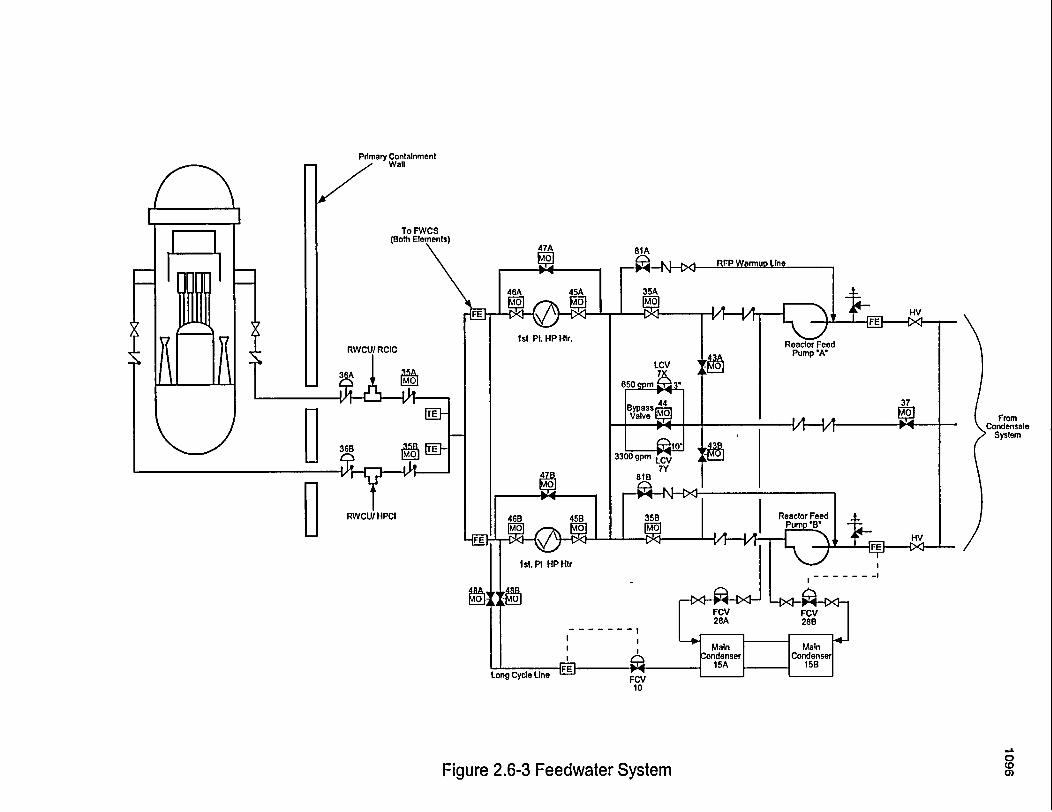
Primary ContainmentZ' Wall
I st Pt. HP Htr.
UFrom
CondensateSystem
0coa)
- -I
I- I
Figure 2.6-3 Feedwater System
Gpne-ral Rlectric Tecnnnolov Manual Reactor Core Isolation System(pnpr�1 Fleetu* Teclinn1n�v Manual Reactor Core Isolation System
Table of Contents
2.7 REACTOR CORE ISOLATION COOLING SYSTEM ..............................
2.7.1 System Description ....................................................2.7.2 Component Description ................................................
2.7.2.1 Turbine Trip Throttle Valve ..........................................2.7.2.2 Turbine Control Valve ..............................................2.7.2.3 RCIC Turbine .....................................................2.7.2.4 Pump Suction Valves ...............................................2.7.2.5 RCIC Pump ..........2.7.2.6 RCIC Flow Controller ...............................................
2.7.3 System Features ...................................................2.7.3.1 RCIC Automatic Initiation ...........................................2.7.3.2 Automatic Isolation .................................................2.7.3.3 RCIC Turbine Trips ................................................
2.7.4 System Interfaces .....................................................2.7.4.1 Main Steam System ................................................2.7.4.2 Primary Containment System .........................................2.7.4.3 Condensate and Feedwater ...........................................
2.7.5 Summary .............................................................
List of Figures
Figure 2.7.1 .................................... Reactor Core -Isolation Cooling System
Rev UIUUUSNRC Technical Training Center 2.7-iUSNRC Technical Training Center 2.7-i Rev 0100
- General Electric Technoloev Manual -Reactor Core Isolation System- Cene~lEletrc Tcholov anul eacorCor Iolaio Syte
2.7 REACTOR CORE ISOLATION-COOLING SYSTEM
The purposes of the Reactor Core IsolationCooling (RCIC) System are to provide riiakeupwater to the reactor vessel for core cooling when:
1. The main steam lines are isolated.-
2. The condensate and feedwater-system is' notavailable.
The functional classification of the RCIC Systemis that of a safety related system.
2.7.1 System Description
The-RCIC System (Figure 2.7-1) consist of a'steam turbine driven pump, with the necessarypiping and'valves'capable of delivering.water tothe reactor vessel at operating conditions.
The turbine is driven by steam produced in thereactor and exhausts to the suppression pool. Theturbine driven pump unit supplies makeup waterfrom the -condensate storage tank, with analternate supply from the suppression pool, to thereactorvessel viathe feedwaterpiping. Additionaldischarge flow paths are provided to allowrecirculation to the condensate storage-tank for-system testing and a pump minimum flow line tothe -suppression 'pool for pump protection.Sufficient capacity is provided to prevent reactorvessel level from decreasing below the top of the
-'core. The system flow rate is approximately equalto reactor water boil off rate 15 minutes aftershutdown with design decay heat.
-Initiation of the RCIC System is-accomplished'automatically on reactor vessel water level low -low or manually by the operator.
2.7.2 Component Description
'The -components of -the RCIC - System arediscussed in the paragraphs that follow.
2.7.2.1 Turbine Trip Throttle Valve
The RCIC turbine trip throttle valve is locatedupstream of the turbine control valve and providesfor rapid turbine isolation -during potentiallyunsafe turbine conditions. Opening of the valve,after a trip, is accomplished from the control roomvia a control switch. Closure of the valve is byspring force and opening is done by an electricmotor. -
2.7.2.2 Turbine Control Valve
The turbine control valve is opened by springforce and closed by oil pressure. RCIC turbinespeed, and therefore pump flow, can be controlledby throttling the steam supply to the turbine. TheRCIC flow control circuit determines the valveposition necessary to produce the required pumpdischarge flow and then adjusts the oil pressure tothe control valves.
2.7.2.3 RCIC Turbine. -
The RCIC turbine is designedto accelerate rapidly.from ,a cold standby condition to full load
conditions within 20 seconds. The RCIC turbineis a, horizontallyi mounted radial re-entry,noncondensing turbine designed to operate with asteam supply pressure ranging from 1150 psig to150 psig. -The RCIC turbine operates with a 10
;psig 'exhaust pressure, exhausting, to the* supp~ression pool under water.
USNR Tehnicl Tainng Cnte - .7-1i~euiu-USNRC Technical Training Center *2.7-1 -1 Rev 0100
General Electric Technology Manual Reactor Core Isolation SystemGeneral Electric Technology Manual Reactor Core Isolation System
2.7.2.4 Pump Suction Valves
Motor operated valves are used to line up RCICpump suction from either the condensate storagetank or from the suppression pool.
Check valves are provided to prevent flowbetween the condensate storage tank and thesuppression pool when both suction valves areopen. Any time level in the condensate storagetank reaches a minimum level or the suppressionpool reaches a maximum level, the suppressionpool suction valve opens. When the suppressionpool suction valve is fully open, a close signal istransmitted to the condensate storage tank suctionand test return valves.
2.7.2.5 RCIC Pump
The RCIC pump is a turbine driven, horizontal,multistage, centrifugal pump with a capacity of400 gpm. The RCIC pump is designed for watertemperature between 40'F and 140'F. To ensureadequate net positive suction head (NPSH), thepump is located at a lower elevation than itssources of water.
2.7.2.6 RCIC Flow Controller
The RCIC system utilizes a flow controller toautomatically or manually control system flowupon initiation. Selection of either automatic ormanual mode is performed by the control roomoperator. In the automatic mode (normal position),the controller compares actual RCIC System flow(sensed by a flow element on the discharge of thepump) with the desired flow setpoint (adjusted bythe operator at the controller). Any deviationbetween actual and desired flow is then convertedinto a hydraulic signal which positions the controlvalves as required to balance the flow signals. Inmanual mode the operator has direct control ofRCIC system flow. The operator simply adjusts a
manual potentiometer, at the flow controller, tocreate a signal used for positioning the controlvalves to obtain the desired flow.
2.7.3 System Features
A short discussion of the system features is givenin the paragraphs which follow.
2.7.3.1 RCIC Automatic Initiation
Following a reactor scram from power operation,fission product decay continues to produce-heat.This heat will raise reactor pressure causing steamflow to the bypass valves, or through safety/reliefvalves. The steam flow will cause vessel waterlevel to decrease if the feedwater system is notavailable. The- RCIC system will maintainsufficient reactor water level until the reactor isdepressurized and cooled down to a point wherethe shutdown cooling mode of the Residual HeatRemoval System ( Section 10.4) can be placed inoperation.
The RCIC System is automatically initiated ifvessel level decreases to a low - low water level.When the initiation signal is received, severalactions occur. The turbine steam supply shutoffvalve opens to admit steam to the turbine. Thenormal discharge path to the reactor is aligned, thetest return line isolates and at the same time, thedischarge valve to the feedwater piping opens.
As the turbine begins to roll, an attached lube oilpump builds up oil pressure and the turbine flowcontrol system begins to throttle the turbinecontrol valve. As the turbine speed continues toincrease pump flow and discharge pressureincrease until a flow of 400 gpm is achieved (flowcontroller setting).
Once initiated the RCIC will remain in operationuntil manually secured an automatic isolation
USNRC Technical Training Center 2.7-2 Rev 0100USNRC Technical Training Center 2.7-2 Rev 0100
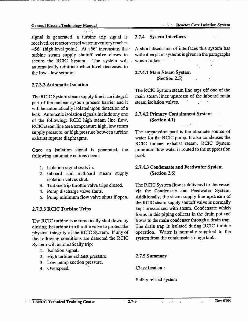
General Electric Technology Manual ,~~~~~~ ~ ~ , eco.rlslto~se
General Electric Technoloev Manual - Reactor Core Isolation System
signal is generated, a turbine trip signal isreceived, or reactor vessel waterinventory reaches+56" (high level point). At +56" increasing, theturbine steam supply shutoff valve closes tosecure the RCIC System. The system willautomatically reinitiate when level decreases tothe low - low setpoint.
2.7.3.2 Automatic Isolation
The RCIC System steam supply line is an integralpart of the nuclear system process barrier and itwill be automatically isolated upon detection of aleak. Automatic isolation signals include any oneof the following: RCIC high steam line flow,RCIC steam line area temperature high, low steamsupply pressure, or high pressure between turbineexhaust rupture diaphragms.
Once an isolation signal is generated, thefollowing automatic actions occur:
1. Isolation signal seals in.2. Inboard and outboard steam supply
isolation valves shut.3. Turbine trip throttle valve trips closed.4. Pump discharge valve shuts.5. Pump minimum flow valve shuts if open.
2.7.3.3 RCIC Turbine Trips
The RCIC turbine is automatically shut down byclosing the turbine trip throttle valve to protect thephysical integrity of the RCIC System. If any ofthe following conditions are detected the RCICSystem will automatically trip:
1. Isolation signal.2. High turbine exhaust pressure.3. Low pump suction pressure.4. Overspeed.
2.7.4 System Interfaces
A short discussion of interfaces this system haswith other plant systems is given in the paragraphswhich follow.
2.7.4.1 Main Steam System(Section 2.5)
The RCIC System 'steam line taps off one of themain steam lines upstream of the inboard mainsteam isolation valves.
2.7.4.2 Primary Containment System(Section 4.1)
The suppression pool is the alternate source ofwater for the RCIC pump. It also condenses theRCIC turbine exhaust steam. RCIC Systemminimum flow water is routed to the suppressionpool.
2.7.4.3 Condensate and Feedwater System(Section 2.6)
The RCIC System flow is delivered to the vesselvia the Condensate and Feedwater System.Additionally, the steam supply line upstream ofthe RCIC steam supply shutoff valve is normallykept pressurized with steam. Condensate whichforms in this piping collects in the drain pot andflows to the main condenser through a drain trap.The drain trap is isolated during RCIC turbineoperation. Water is normally supplied to thesystem from the condensate storage tank.
2.7.5 Summary
Classification:
Safety related system
USNRC Technical Training Center 2.7.3 Rev 0100t '- USNRC Technical Training Center 1 2.7-3 - - Rev 0100
General Electric Technologv Manual r---tn T-1rP - Cclt~n.-vt--1-EU -- n -.. AVA jlat[Ul~M a
Purpose:
To provide makeup water to the reactor vessel forcore cooling when: The main steam lines areisolated. The condensate and feedwater system isnot available.
Components:
Steam supply isolation valves; turbine trip throttlevalve; turbine control valve; turbine; turbinedriven pump; and flow controller.
System Interfaces:
Main Steam System; Primary ContainmentSystem; Condensate and FeedwaterSystem.
USNRC Technical Training Center 2.7-4 Rev 0100USNRC Technical Training Center 2.7-4 Rev 0100
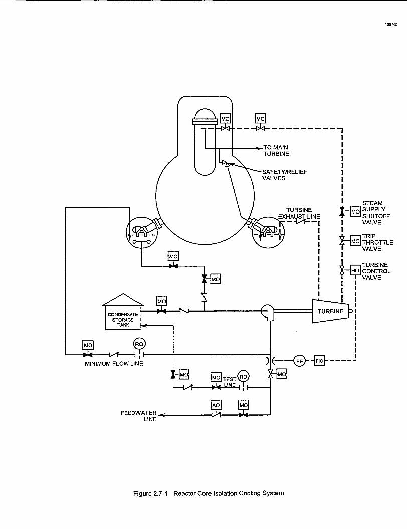
1097-2
- TO MAIN ITURBINE I
~ISAFETY/RELIEF IVALVES I
TURBINESTEAM
1 SUPPLY
-IIIIIIIIIII
* =IV SHUTOFFI VALVE
|~ TRIPTHROTTLEVALVE
TURBINEHO CONTROLI VALVE
I I
I I
i
MINIMUM FLOW LINE
Figure 2.7-1 Reactor Core Isolation Cooling System
General Electric Technology Manual Reactor Water Cleanup System
Tabel of Contents
2.8 REACTOR WATER CLEANUP SYSTEM.
2.8.1 System Description..12.8.2 Component Description.. 1
2.8.2.1 RWCU Inlet Piping . . .12.8.2.2 RWCU Pumps . . . 12.8.2.3 Regenerative Heat Exchangers. . . 12.8.2.4 Nonregenerative Heat Exchangers ..................................... 12.8.2.5 Filter/Demineralizer Units ............................ . 22.8.2.6 RWCU Outlet Piping ............................. . 2
2.8.3 System Features ............................................... 22.8.3.1 System Operation ............................. . 2
2.8.3.1.1 Normal Operation ............................................ 32.8.3.1.2 Blowdown .............................................. 3
2.8.3.2 Filter/Demineralizer Operations ........................... . 32.8.3.2.1 Backwashing .............................................. 32.8.3.2.2 Precoating .............................................. 4
2.8.3.3 Isolation ............................. . 42.8.4 System Interfaces ............................................... 4
2.8.4.1 Recirculation System .............................................. 42.8.4.2 Reactor Vessel System .............................................. 42.8.4.3 Condensate and Feedwater ............................ . 42.8.4.4 Liquid and Solid Radwaste Systems ............................ . 42.8.4.5 Reactor Building Closed Cooling Water System ..................... . 4
2.8.5 Summary .................................. 5
List of Figures
Figure 2.8.1 .. . Reactor Water Cleanup SystemFigure 2.8.1 .. . . Reactor Water Cleanup System (detail)
USNRC Technical Training Center 2.8-i Rev 0100
I General Electric Technolozv Manual � , - . - I Reactor Water Cleanun SvstemGeneral Electric Technoloffv Manual - Reactor Water Cleanuu System
- 2.8 REACTOR WATER CLEANUP - provided by a line from the reactor vessel bottom' ; SYSTEM - I head drain. Isolation valves are provided both
inside and outside of the primary containment for
The purposes of the Reactor Water Cleanup -' isolating the RWCU system, during, unsafe(RWCU) System are: - * i ' -conditions. . mI
1.- To maintain reactor water quality by filtration 2.8.2.2 RWCU Pumpsand ion exchange. ,
-Two RWCU pumps provide the needed motive2. To provide a path for removal of reactor force for 'water flow from the recirculation loop,
coolant when required. - through the RWCU system and back to the reactor
'-iThe functional- classification of the RWCUSystem is that of a power generation system.
2.8.1 System Description
The RWCU System, shown in Figure 2.8-1,provides a continuous purification of a portion ofthe'reactor-recirculation system flow. Water is
* taken from the Reactor Recirculation System (seesection 2.4) piping -and pumped through theregenerative and nonregenerative heat exchangers,-filter/demineralizers and returned through theshell side of the regenerative heat exchanger to thefeedwater- piping. The RWCU system alsoremoves a small portion of water from the reactorvessel bottom head drain to reduce any crudbuildup and possibility of cold water stratification.
vessel via the -feedwater system. The RWCUpumps are motor'driven, horizontally mounted,centrifugal pumps. Both pumps together provide100% system flow which corresponds toapproximately 1% of rated feedwater flow.
2.8.2.3 Regenerative Heat Exchangers
-The first- stage of temperature reduction isaccomplished -by uthree regenerative heatexchangers arranged in series. The regenerativeheat exchangers transfer heat from' the influentreactor water-by preheating the RWCU system'seffluent. This results in less _ystem heat loss andless thermal stress as the effluent water enters thefeedwater system.,-.
2.8.2.4 Nonregenerative Heat Exchangers
2.8.2 ' 'Component Description The nonregenerative heat exch'angers provide the* -final reduction of water temperature prior to entry
'The major components of the RWCU system are ' into the filter/demineralizers. Unlike thediscussed in the paragraphs which follow and can ' regenerative heat exchangers ,the heat removed in
' be seen inFigure 2.8-1. the honregenerative heat exchangers is lost toanother system, the Reactor Building Closed
- 2.8.2.1VRWCU Inlet Piping -Cooling Water System ( Section 11.1).- * - ,' - } . , a I
- The- major flow' of the RWCU system is taken '2.8.2.5 Filter/Deminieralizer Unitsfrom the suction of the -'A' recirculation pump;lThis sluction is'comnion to the shutdown cooling -The purpose'of-the filter/deriineralizers is to'node of the Residual Heat Removal -Sstem remove soluble and insoluble impurities from the(Secti6n'10.4). An additional sourcefoftwater is - reactor water. This process is accornplished by the
USNRC Technical Training Center - - 2.8-1 - - Rev 0100USNRC Technical Training Center -- 2.8-1 Rev 0100
General Electric Technoloev Manual Reactor Water Cleanup SvstemGeea Elcti _eboe Maua Reco Wae C-au Systemv
water flowing through a finely ground filter aidmaterial (Solka-Floc) and ion exchange resins.
The two filter/dernineralizer units (Figure 2.8-2)are of a pressure precoat type in which the vesselfilter tubes are coated with a filter aid andpowdered ion exchange resin. These materialsserve as the filter media and ion exchange agentand'are held on to the screen type tubes by thedifferential pressure generated by the waterflowing through each unit. Flow through thesystem is automatically controlled by flow controlvalves located at the outlet of eachfilter/demineralizer.
Each unit is composed of a pressure vessel whichcontains the filter tubes, a holding pump,instrumentation, controls, valves, and piping. Airoperated inlet and outlet isolation valves and theflow control valve are furnished for eachfilter/demineralizer unit to permit individualoperation and serving. Auxiliary componentsrequired for precoating, backwashing, anddisposal of the filter media are shared by bothfilter/demineralizers.
2.8.2.6 RWCU Outlet Piping
Filter/demineralizer effluent line branches intotwo lines, one line routing water to theregenerative heat exchangers and the other to theblowdown control section. During normal systemoperation, flow is routed through the shell side ofthe regenerative heat exchangers, a motoroperated discharge isolation valve and into thefeedwater lines.During other operations requiring reactor vesselblowdown, a portion of the flow is routed to themain condenser (Section 2.6) or to the LiquidRadwaste System (Section 8.2). Blowdown flowis directed through a commonheader which iscontrolled by a flow control valve and a restrictingorifice. The restricting orifice provides a largepressure drop to protect the low pressure
downstream piping. If additional flow is required,a motor operated orifice bypass valve can beopened.
2.8.3 System Features
A short discussion of the system features is givenin the paragraphs which follow.
2.8.3.1 System Operation
The RWCU system is normally operatedcontinuously during all phases of reactor plantoperation to maintain undissolved solids less than0.01 ppm and conductivity less than 0.1 micromho/cm. Blowdown (draining) is normally usedonly to remove excess water from the reactorvessel.
Reactor water quality depends on several factors:corrosion of primary system materials, input ofimpurities and- corrosion products from theCondensate, and Feedwater System, pipingdeposition and re-entrainment at system surfaces,radioactive decay, and removal of impurities(corrosion products and fission products) by thefilter/demineralizers.
Impurities in the reactor water are of two forms,soluble and insoluble. By definition, insolublematerial is that collectible on a type HA milliporefilter paper; the remainder is soluble. The solublematerials are suspended in the water untilcollected or plated onto some surface.The insoluble materials are removed by filtration.Corrosion product inputs from the primarysystems have been minimized by use of stainlesssteel vessels, pipes, and heat exchangers. Themajority of corrosion product input originates inthe condenser and feedwater components wherecarbon steel piping, and components, are, used.Cleanup system operation is necessary to maintainreactor water purity. Reactor operation without the
USNRC~~~~~~~~~ TcnclTinnCetr2-2Rv00IUSNRC Technical Training Center 2.8-2 Rev 0100
� I General Electric Technoloev Manual -Reactor Water CleanuiD Svstem-Geearlcri ehoov MaulRatrWtrCenpSse
- cleanup system is limited to relatively short Iperiods of time. -
2.8.3.1.1 -Normal Operation.
During normal operation water is taken from thereactor recirculation system piping and pumped.:through the regenerative and nonregenerative heat 1exchangers, both filter/demineralizers,, and ireturned through the shell side of the regenerativeheat exchanger to the feedwater piping. TheRWCU also -removes a small portion of waterfrom the reactor vessel bottom head drain (Section2.1) to reduce any crud buildup. i
2.8.3.1.2 Blowdown
During a plant startup, shutdown, or low steamingrates, it is sometimes necessary for the operator todrain water from the vessel in order to maintain aproper vessel level. This is done with theblowdown portion of the RWCU System. Water,from the outlet of the filter/demineralizers, can berejected to the main condenser or to the LiquidRadwaste System rather than being returned to thevessel., In this way water is removed from thereactor. The blowdown flow rate is controlledmanually from the control. room -as shown onFigure 2.8-2. The hand operated controller is setto the desired flow and the appropriate motoroperated valve is opened, directing flow to eitherthe main condenser or to the-Liquid RadwasteSystem. The main condenser is the preferred iblowdown point in order to limit the duty on theliquid waste processing facilities. During theblowdown operation, the greatest duty is imposed -lon the non-regenerative heat exchangers becausemuch of thereturn flow that was going to theregenerative heat exchangers is now bypassing lthem. If,- during :*blowdown, operation, -high ipressure is sensed downstream of the, blowdowncontrol valve or if low pressure is sensed,upstream, the blowdown control valve isautomatically closed. The high pressure sensor
protects the piping downstream of the controlvalve and the low pressure sensor preventsdraining the entire RWCU System piping in asiphon action'to the main condenser or radwaste.
Z.83.2 Filter/Deminiralizer Operations
rwo filter/demineralizer operations are discussedin the paragraphs which follow.
Z.83.2.1 Backwashing
A's the differential - pressure - across afilter/demineralizer unit approaches 20 psid, or if:he outlet conductivity reaches 0.lurfihos.- thefilter/demineralizer is removed from service forbackwashing and precoating. --
Backwashing consists of removing the spentresins from the filter/ demineralizer holdingelements. This is accomplished by the use of anair blast injected into the filter/demineralizer toJislodge the precoat. Condensate is then pumfipedinto the filter/ demineralizer through the outletline. The -drain line is, then opened, and themixture of water and spent resins is pumped to thecleanup phase separator tank of the radwastefacilities.
2.83.2.2 Precoating
After the filter/demineralizer is backwashed, it isnow ready for a new application of resins. Thefilter/demineralizer is precoated by circulating aslurry of the resin from the resin feed tank ontothe stainless steel resin holding elements. -
The slurry deposits evenly on the elements whilethe waterreturns to the resin-feed tank. Precoatrecirculation continues until the return water isclear. At this time, a holding pump isautomatically started to maintain the precoat inplace on the holding- elements. -Thefilter/demineralizer is then returned to service, and
USNR Tehnial Tainng entr '28-3Rev01WUSNRC Technical Training Center - 2.8-3 - Rev 0100
General Electric Technologv Manual uRsaet-m Wat."r i.-nln.-vt_ _ _ _____-__- __ _ . I_ *\-HaTvam s-u o~r
the holding pump flow stops as system flowincreases.
The holding pump for each filter/demineralizerunit is automatically restarted if thefilter/demineralizer outlet flow drops below 90%.This ensures a flow through thefilter/demineralizer at all times and prevents theprecoat from falling off the elements.
2.8.3.3 Isolation
The inboard and outboard system supply isolationvalves automatically close following an isolationsignal from any one of the following:
1. Low reactor water level2. Standby Liquid Control System actuation3. High temperature filter/demineralizer inlet4. High area temperature5. Area drain temperature high
2.8.4 System Interfaces
A short discussion of interfaces this system haswith other plant systems is given in the paragraphswhich follow.
2.8.4.1 Recirculation System (Section 2.4)
The main condenser can be used to collect waterfrom RWCU System blowdown.
2.8.4.4 Liquid and Solid Radwaste Systems(Sections 8.2 and 8.3)
The radwaste facilities are used to collect waterfrom RWCU blowdown and spent resins from thefilter demineralizers.
2.8.4.5 Reactor Building Closed CoolingWater System (Section 11.1)
The Reactor Building Closed Cooling WaterSystem provides cooling water to the RWCUpumps and the non regenerative heat exchangers.
2.8.5 Summary
Classification:
Power Generation System
Purpose:
To maintain reactor water quality by filtration andion exchange.Provides a path for removal ofreactor coolant when required.
The Recirculation System supplies water to theRWCU System.
2.8.4.2 Reactor Vessel System (Section 2.1)
The reactor vessel provides water to the RWCUSystem via the bottom head drain line.
2.8.4.3 Condensate and Feedwater System(Section 2.6)
The Condensate and Feedwater System providesa return path to the vessel for the processed water.
Component:
Isolation valves; pumps; regenerative heatexchangers; nonregenerative heat exchangers;filter/demineralizers.
System Interfaces:
Recirculation System; Reactor Vessel andInternals System; Condensate and FeedwaterSystem; Radwaste Systems; Reactor BuildingClosed Cooling Water System
USNI{C Technical Training Center 2.8-4 Rev 0100USNKU Technical Training Center 2.8r4 Rev 0100
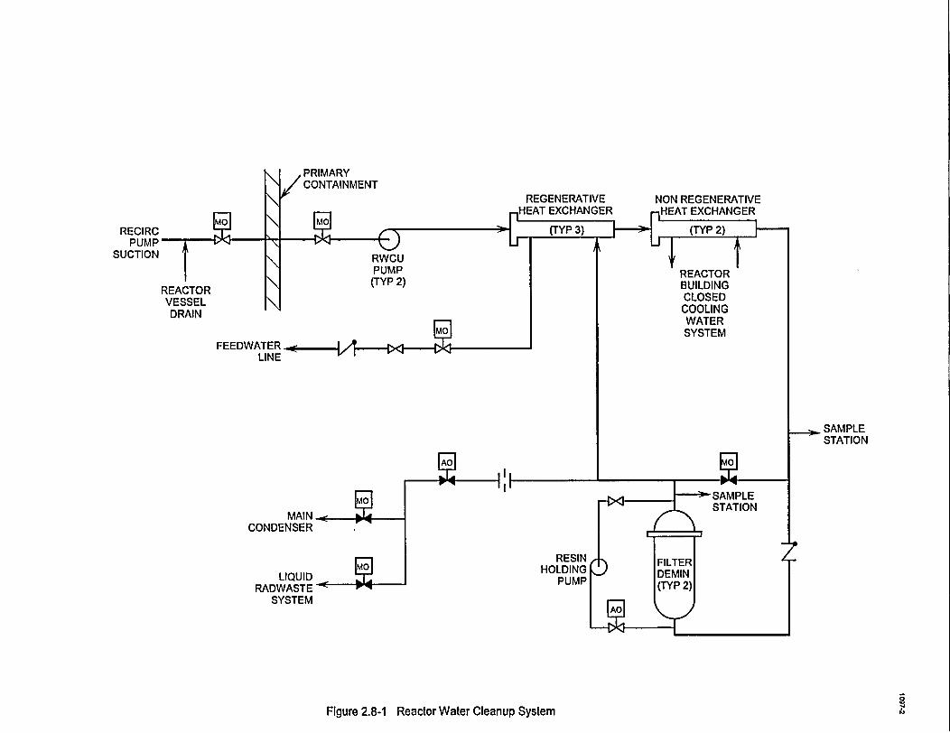
REGENERATIVE NONIEAT EXCHANGER -HEA
RECIRCPUMP
SUCTION RWCUPUMP(TYP 2)
REACTORVESSELDRAIN
WATERSYSTEM
SAMPLESTATION
, -
MAINCONDENSER
LIQUID ERADVWASTE
SYSTEM
9Figure 2.8-1 Reactor Water Cleanup System
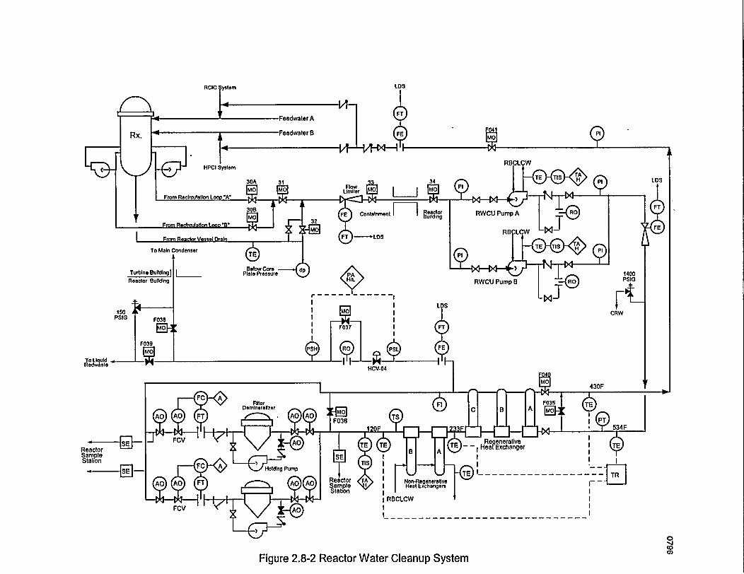
RCIC LDS
Reactor Building RVCU Pump 13
r -l - - -
150 A CRWPSIG F038
quI~d F039
To LlquldRedwasie HCV-04
FilCer 35Derrilneralfoer P
Reactor El[xhneSamplStati-o'n SE PC A e Holding Pump RTt E I
Sample , Hea Exchgers
| | >F ,RBCLCWFCV
(0
Figure 2.8-2 Reactor Water Cleanup System