bv robert n. quade
TRANSCRIPT

bv ROBERT N. QUADE
DISCLAIMER
This report was prepared as an account of work sponsored by an agency of the United States Government. Neither the United States Government nor any agency Thereof, nor any of their employees, makes any warranty, express or implied, or assumes any legal liability or responsibility for the accuracy, completeness, or usefulness of any information, apparatus, product, or process disclosed, or represents that its use would not infringe privately owned rights. Reference herein to any specific commercial product, process, or service by trade name, trademark, manufacturer, or otherwise does not necessarily constitute or imply its endorsement, recommendation, or favoring by the United States Government or any agency thereof. The views and opinions of authors expressed herein do not necessarily state or reflect those of the United States Government or any agency thereof.

DISCLAIMER
Portions of this document may be illegible in electronic image products. Images are produced from the best available original document.

This report was prepared as an account of work sponsored by the United States Government. Neither the United States nor the Department of Energy, nor any of their employees, nor any of their contractors, subcontractors, or their employees, makes any warranty, express or implied, or assumes any legal liability or responsibility for the accuracy, completeness or usefulness of any information, apparatus, product or process disclosed, or represents that its use would not infringe privately owned rights.

warranty. expreU or implied. or awmer any legal liability 0. retponribilily for the accurscy. mmpleleneu. or u*fulnw 01 any informalion, appaialul. product. or proces didoIBd. 01
rarerents that its u s xavld mi inlringe o r i ~ i e l y o w e d rights. Referem herein to any rpeific
-- - --
DESIGN AND APPLICATION FOR A HIGH-TEMPERATURE NUCLEAR HEAT SOURCE
ROBERT N. QUADE
This k a preprint of a paper to be presented at the Specialists' Meeting on Process Heat Applications Technology, sponsored by the IAEA International Working ' ~ r o u ~ on High Temperature Reactors, November 27-29, 1979, KFA-JUlich, the Federal Republic of Germany, and to be published in the Proceedings.
GENERAL ATOMIC PROJECT 7212 NPVEMBER 1979
4
Work supported by Department of Energy
Contract DE-AT03-76SF71061
I GENERAL ATOMIC COMPANY ,I ' U' 1)llSTRXBUTJON CIF -IS DOCUMENT 18 UNLiMPT@)r

T H I S PAGE
WAS INTENTIONALLY
LEFT BLANK

ABSTRACT
Recent a c t i o n s by OPEC have s h a r p l y i nc reased i n t e r e s t i n t h e United
S t a t e s i n s y n f u e l s , w i th c o a l be ing t h e l o g i c a l choice . f o r t h e carbon
source . Two coal' l i q u e f a c t i o n p roces se s , d i r e c t and i n d i r e c t , have been
examined. Each can produce about 50% more output .when coupled t o an HTGR
f o r process h e a t .
The nuc lear r e a c t o r designed f o r p rocess h e a t ha s a power ou tpu t of
842 MW(t) , ' a co re ou t ' l e t temperature of 950°C (1742"F), and an i n t e rmed ia t e
hel ium loop t o s e p a r a t e t h e h e a t sou rce from t h e process h e a t exchangers.
Steam-methane reforming is t h e r e f e r e n c e process .
A s p a r t of t h e development of a nuc l ea r p rocess hea t system, a compu-
ter code, Process Heat Reactor Evalua t ion and Design, i s be ing developed.
Th i s code models bo th t h e r e a c t o r p l a n t and a s team reforming p l a n t . When
complete, t h e program w i l l have t h e . c a p a b i l i t y t o c a l c u l a t e an o v e r a l l
mass and h e a t ba l ance , s i z e t h e p l a n t components, and e s t i m a t e t h e p l a n t
cos t f o r a wide v a r i e t y of independent v a r i a b l e s .
iii

T H I S PAGE
WAS INTENTIONALLY
LEFT BLANK

CONTENTS
ABSTRACT . . . . . . . . . . . . . . . . . . . . . . . . . . . . . . iii INTRODUCTION . . . . . . . . . . . . . . . . . . . . . . . . . . . . 1
RESOURCES VERSUS ENERGY N.EEDS . . . . . . . . . . . . . . . . . . . . 1
COAL TO SYNFUEL PROCESSES . . . . . . . . . . . . . . . . . . . . . 4
Coal t o Liquid Fuel Processes . . . . . . . . . . . . . . . . . . 4
Goal t o p i p e l i n e Gas Processes . . . . . . . . . . . . . . . . 9
NUCLEARHEATSOURCE . . . . . . . . . . . . . . . ' . . . . . . . . . . 9
COMPONENTDESCRIPTION . . . . . . . . . . . . . . . . . . . . . . . 13
P r e s t r e s s e d Concrete Reactor Vessel . . . . . . . . . . . . . . 13
T h e r m a l B a r r i e r . . . . . . . . . . . . . . . . . . . . . . . . 14
Reactor Core . . . . . . . . . . . . . . . . . . . . . . . . . . 14
. . . . . . . . . . . . . . . . . . In te rmedia te Heat Exchanger 16
~ e l i u m C i r c u l a t o r s . . . . . . . . . . . . . . . . ' . . . . . . 17
Reformers . . . . . . . . . . . . . . . . . . . . . . . . . . . . . 17
SteamGenera tors . . . . . . . . . . . . . . . . . . . . . . . 18
. . . . . . . . . . . . . P l a n t Sa fe ty and Emergency'Core Cooling 18
Balance of Reactor P l a n t . . . . . . . . . . . . . . . . . . . 19
. . . . . . . . . . . . . . . . . . PLANT DESIGN AND PERFORMANCE CODE 21
. . . . . . . . . . . . . . . . . . . . . . . . . Heat Exchangers 23
. . . . . . . . . . . . . . . . . In te rmedia te Heat Exchanger 23
. . . . . . . . . . . . . . . . . . . . . . . . . . . Reformer 28
. . . . . . . . . . . . . . . . . . . . . . Steam Generator 28
. . . . . . . . I n t e r a c t i o n of Process P l a n t and Nuclear P l a n t 29
. . . . . . . . . . . . . . . . . . . . . . . . . . . . . . CONCLUSIONS 30
REFERENCES . . . . . . . . . . . . . . . . . . . . . . . . . . . . . . 31
FIGURES
Coal t o jet f u e l : v i a Lurgi-Fischer-Tropsch synthes is . . . . . 5
Coal t o jet fue l : using VHTR reforming f o r H2 (prime) . . . . . . . . . . . . . . . . . and using HTGR f o r u t i l i t i e s 7
. . . . . . . . . . . . . . . . . . . HTGR-process h e a t source 11
. . . . . . . . . . . . . . . . HTGR-process h e a t flow diagram 12
. . . . . . . . . . Twin 842-MW(t) HTGR-process hea t p l o t plan 20
. . . . . . Top l e v e l l o g i c diagram f o r the PHRED computer code 24
Schematic loop arrangement f o r VHTR hydrogen production . . . . . . . . . . . . . . . . . . . . . . . . process p lan t 25
. . . . . . . . . . . . . . . . . . IHX computer model flowsheet 27
TABLES
. . . . . . . . . . . . . . . . . . . . 1 . U.S .. energy consumption 2
2 . Estimated t o t a l remaining recoverable resources i n the U . s.' . . 2
3 . Comparison'of nuclear and non-nuclear coal l iquefac t ion . . . . . . . . . . . . . . . . . . . . . . . . . . . processes 8
. . . . . . . . . . . . . . . . . 4 . Component design parameters 15
. . . . . . . . . . . . 5. . Values of independent design va r iab les 22

INTRODUCTION
The U.S. program on n u c l e a r p r o c e s s h e a t was s t a r t e d i n t h e mid-1960s
and became focused on c o a l g a s i f i c a t i o n i n 1971. The program h a s b e n e f i t e d
from t h e l a r g e h igh- tempera tu re gas-cooled r e a c e o r (HTGR) g e n e r i c t e c h n o l -
ogy program i n t h e Uni ted S t a t e s , a l t h o u g h t h e s p e c i f i c p r o c e s s h e a t pro-
gram h a s been smaller than t h e s t e a m c y c l e and gas t u r b i n e programs.
Recent a c t i o n s by OPEC have s h a r p l y i n c r e a s e d U.S. i n t e r e s t i n syn-
f u e l s , and c u r r e n t l y t h e r e a r e p l a n s f o r s e v e r a l t y p e s of s y n f u e l demon-
s t r a t i o n p l a n t s . The e a r l y t i m i n g o f t h e s e p l a n t s w i l l p robab ly p r e c l u d e
a n u c l e a r h e a t ' s o u r c e , b u t t h e i r o p e r a t i o n w i l l b e a n e c e s s a r y s t e p toward
t h e e v e n t u a l i n t e g r a t i o n of a n u c l e a r h e a t . s o u r c e .
T h i s paper w i l l ( 1 ) focus on a p p l i c a t i o n s t h a t a r e c u r r e n t l y consid-
e r e d a c t i v e c a n d i d a t e s f o r n u c l e a r p r o c e s s h e a t , (2 ) r ev iew t h e d e s i g n
c o n d i t i o n s imposed by t h e p r o c e s s on t h e n u c l e a r h e a t s o u r c e , (3 ) d e s c r i b e
t h e r e f e r e n c e h e a t s o u r c e d e s i g n w i t h emphasis on t h e h e a t exchangers , and
(4 ) d i s c u s s a computer-based sys tems code t h a t d e s c r i b e s b o t h t h e n u c l e a r
and p r o c e s s p l a n t s f o r o p t i m i z a t i o n purposes .
RESOURCES VERSUS ENERGY NEEDS
As shown i n T a b l e 1 , I1.S. energy demands r e l y h e a v i l y on p e t r o l e u m
and n a t u r a l g a s . Over 75% of t h e b u l k energy demands are m e t b y t h e s e
f u e l s . During t h e las t decade, U.S. energy consumption h a s i n c r e a s e d by
a lmost 3.5% p e r y e a r . A t a cnns i s te 'n t growth a t t h i s r a t e , t h e t o t a l
energy consumption is doubl ing abou t e v e r y 20 y e a r s . The m a j o r i t y of
t h e s e . s p i r a l i n g i n c r e a s e s i n U.S . energy consumption a r e b e i n g . f u l f i l l e d
by a mere 7.9% of t h e e s t i m a t e d t o t a l r emain ing r e c o v e r a b l e U.S. f o s s i l
f u e l r e s o u r c e s , namely pe t ro leum and n a t u r a l gas . Even i f P r e s i d e n t

Resources
Petroleum
Na tu ra l gas
Coal
, Hydropower
~ u c i e a r
TABLE 1 U.S. ENERGY CONSUMPTION
J o u l e s x 10 18 Percent
TABLE 2 ESTIMATED TOTAL REMAINING RECOVERABLE
RESOURCES I N THE U.S.
. Resources J o u l e s x 10 l 8 percent
Coal 36,300 77.3
Sha le o i l 6,700 14.4
Crude o i l 2,100 4.5
N a t u r a l gas 1,600 3.4
Na tu ra l gas l i q u i d s 200 0.4 ...
46,900 100.0

C a r t e r ' s suggested r a t e of 2% per year could b e achieved, consumption
would double i n 35 yea r s .
A s shown i n Table 2 , over t h r e e q u a r t e r s of t h e es t imated t o t a l
remaining recoverable f o s s i l f u e l i n t h e United S t a t e s is i n t h e form of
coa l . However, coa l c u r r e n t l y accounts f o r only 18% of t h e energy con-
sumed i n t h e United S t a t e s .
It i s imposs ib le t o expect n a t u r a l gas , which produces over 30% of
t h e U . S . energy, t o maintain i t s hold over s u c h . a l a r g e s h a r e of t h e
energy produced i n t h e United S t a t e s . The l i m i t e d a v a i l a b i l i t y of n a t u r a l
gas w i l l r e q u i r e t h a t o t h e r energy resources be u t i l i z e d . S ince o i l i s
t h e predominant f u e l used i n t h e United S t a t e s , i t would b e a l o g i c a l
a l t e r n a t i v e f o r t ak ing up t h e ma jo r i t y of t h e burden caused by reduced
n a t u r a l gas usage. However, P re s iden t Ca r t e r has s t a t e d t h a t o i l imports
w i l l no t r i s e above 1977 l e v e l s and domestic resources a r e inadequate t o
* I meet t h e increased demand. Coal and n u c l e a r power remain among proven
energy sources f o r meeting U.S .' energy requirements . Coal is the most
abundant remaining f o s s i l f u e l i n t h e United S t a t e s ; It t h e r e f o r e fol lows
t h a t c o a l should b e u t i l i z e d t o t h e maximum degree' t o meet t h e i n c r e a s i n g
U.S. energy requirements .
Approximately 150 b i l l i o n tons (U.S.) of recoverable coa l - 45 b i l l i o n
loca t ed n e a r t h e s u r f a c e and 105 b i l l i o n l o c a t e d more deeply und&rgrbund -
e x i s t i n . fo rma t iono of t h i ckness and d e p t h t n h e mtned economically u t i l i z -
i n g present technology. However, t h e r e is a l i m i t e d r a t e a t ' whfc1-1 t h i s
r e sou rce can be u t i l i z e d , a r a t e determined by t h e a b i l i t y t o cons t ruc t t h e
mining equipment, t h e t r a n s p o r t a t i o n .network, and t h e r e l o c a t i o n and t r a i n -
i n g of t h e miners. There is a l s o cons iderable concern about t h e environ-
mental e f f e c t s . t h a t a v a s t i n c r e a s e i n coa l mining and u t i l i z a t i o n mighe
b r i n g . Large c o a l s i t e s i n t h e United S t a t e s a r e . g e n e r a l l y i n t h e West
where water i s s h o r t , t h e l abo r f o r c e is smal l , and environmental s tandards
a r e very high.. A r e p o r t by t h e Department of Energy (DOE) has concluded
t h a t a 2 m i l l i o n b a r r e l pe r day product ion l e v e l w i l l f a c e " r ap id ly

i n c r e a s i n g s i t i n g d i f f i c u l t i e s " (Ref. 1 ) . It a l s o concluded t h a t only 41
s i tes i n t h e United S t a t e s would meet DOE environmental c r i t e r i a .
General Atomic b e l i e v e s t h a t nuc lea r process hea t can m a t e r i a l l y
improve t h e s e problems of c o a l product ion and environmental impacts by
i n c r e a s i n g t h e product ion of syn fue l s from a given amount of coa l .
COAL TO SYNFUEL PROCESSES
COAL TO LIQUID FUEL PROCESSES
Genera1,Atomic has r e c e n t l y been looking a t ways t o produce l i q u i d
s y n f u e l w i t h a nuc lea r h e a t sou rce and has examined t h e two major process
r o u t e s : i n d i r e c t and d i r e c t .
The i n d i r e c t method, shown i n Fig. 1 , uses cu r r en t s ta te -of - the-ar t
technology f o r t h e product ion of polymer gaso l ine / j . e t f u e l from coal . An
HTGR is i n t e g r a t e d i n t o t h e process and s u p p l i e s t h e u t i l i t i e s (steam and
e l e c t r i c i t y ) and .process hea t ( reformjag) . I n t h e process , bituminous
c o a l i s g a s i f i e d w i t h s team and oxygen i n Lurg i f i x e d bed g a s i f i e r s a t
about 2.7 MPa (400 p s i a ) . Lu rg i g a s i f i e r s produce a romat ic l i q u i d s and
t a r o i l , which a r e scrubbed from t h e off-gas and recovered a s by-products.
The g a s i f i e r off-gas i s then t r e a t e d f o r carbon d ioxide and hydrogen s u l -
ph ide removal i n "Rect i so l" u n i t s where CO and H S a r e absorbed and then 2 2 s t r i p p e d from t h e -48OC (-55OF) r e c i r c u l a t i n g s t ream of methanol.
A f t e r p u r i f i c a t i o n , t h e f eed gas ( s t ream 1) and a recyc led t a i l gas
s t r eam (s t ream 2) from t h e Fischer-Tropsch s y n t h e s i s . s e c t i o n a r e mixed
(s t ream 3 ) , r ehea t ed , and then mixed w i t h a Synthol i n t e r n a l r e c y c l e gas
s t r eam b e f o r e e n t e r i n g t h e Synthol f l u i d bed r e a c t o r (s t ream 4 ) . CO and
H r e a c t i n t h e presence of a n i r o n powder promoted wi th small q u a n t i t i e s 2 of Group I o r Group 111 meta l s . The r e a c t o r temperature is c o n t r o l l e d by
o i l c o o l e r s . Heat absorbed by t h e o i l ' i s used t o gene ra t e p lan t steam.
React ion products a r e scrubbed and condensed from t h e s y n t h e s i s of f-gas.

I I I ' - 1596 MM SCF 146 MM SCFD
I 2163 MM SCFD REFORMER 1338
I 4 PURGED GAS
- 779 MW(t)
:M SCFD A
I LURGl 1610 M v SCFD GASIFICATION COAL
30,755 T!CD I AND O2, PURIFICATION
b '
I - 4123 MM SCFD
I . . 67,149 BBLICD I I ~ , I ~T ,CD b HEATER
I - JET FUEL
I SYNTHO L
OXYGEN 7896 MM SCFD 6941 BBLICD
I JmLl 656 I ALCOHOLS
NAPHTHA, TAR, TAR OIL
ILLINOIS NO. 6 BITUMINOUS
Fig. 1 . Coal to j e t fue l : v ia Lurgi-Fischer-Trspsch synthesis

Chemical p roduc t s ( a l c o h o l s and ke tones) a r e s epa ra t ed from t h e o i l prod-
u c t s by d i s s o l u t i o n i n w a t e r . The hydrocarbon products a r e h igh ly o l e f i n i c
and a r e c a t a l y t i c a l l y polymerized t o form gaso l ine and/or j e t f u e l .
A p o r t i o n of t h e t a i l gas from t h e Synthol r e a c t o r i s purged t o pre-
v e n t n i t r o g e n b u i l d u p . i n t h e system (s t ream 5) . The rest of t h e t a i l gas
i s scrubbed t o remove CO and recyc led through a very h igh temperature 2 r e a c t o r (VHTR) re former , where t h e 25 mole % methane composition can b e
reformed t o hydrogen and carbon monoxide f o r r euse . The steam-to-carbon
r a t i o i n t h e re former i s 'L1.5. The h e a t recovered from t h e 7 6 0 " ~ ( 1 4 0 0 " ~ )
re former o u t l e t s t r eam is used t o produce t h e re£ormer steam.
The second p roces s is t h e d i r e c t p roces s , a s shown i n F ig . 2 . The
c o a l l i q u e f a c t i o n s t e p could b e any of t h e processes c u r r e n t l y under devel-
opment, such a s SRCII (Gu l f ) , Donor Solvent (Exxon) , o r H-Coal (Hydrocar-
bon Research I n c . ) . The p roces s produces c o a l l i q u i d s by mixing ( s l u r r y -
i n g ) d r i e d , f i n e l y ground c o a l wi th a c o a l l i q u i d product . Hydrogen i s
added t o t h e r e s u l t i n g s l u r r y and t h e mixture i s then hea t ed t o 400°C
(750°F) a t 10 MPa (1500 p s i ) w i t h s team from t h e HTGR, where t h e hyd rng~na -
t i o n r e a c t i o n proceeds w i t h c o l d hydrogen added f o r temperature c o n t r o l .
The r e s u l t i n g products a r e s e p a r a t e d i n t o a f u e l o i l and l i g h t d i s t i l l a t e
product which i s f u r t h e r t r e a t e d w i t h hydrogen t o produce jet f u e l . A
p o r t i o n of t h e p roduc t , con ta in ing c o a l a sh , which has a c a t a l y t i c e f f e c t
on t h e c o a l hydrogena t ion r e a c t i o n , is r ecyc l ed t o make t h e c o a l s l u r r y .
A s l u r r y of undisso lved c o a l and ash i s s e n t t o a coker t o i n c r e a s e t h e
y i e l d of f u e l o i l product by about 24%. The coke product from t h e coker
is mixed w i t h steam and oxygen and s e n t t o a Texaco p a r t i a l ox ida t ion
r e a c t o r t o make a product of t h e hydrogen used i n t h e process and y i e l d
a n envi ronmenta l ly a c c e p t a b l e n e u t r a l a sh . The methane produced i s used
a s f e e d s t o c k t o t h e steam-methane reformer which is hea t ed by t h e HTGR.
Table 3 shows a comparison of n u c l e a r and non-nuclear c o a l l i que fac -
t i o n p roces se s . B a s i c a l l y , f o r . e a c h process t h e a d d i t i o n of t h e nuc lear
r e a c t o r can dec rease t h e c o a l requirements by 33% f o r t h e same product
o u t p u t o r f o r t h e same c o a l requirements can I n c r e a s e t h e product ou tput
by 50%.

PIPELINE GAS 72 MM SCFD
I LPG 5370 BBLICD I
ILLINOIS NO. 6 BITUMINOUS
Fig. 2 . Coal t o j e t f u e l : using VHTR reforming for H2 (prime) and using HTGR f o r u t i l i t i e s

TABLE 3 COMPARISON OF NUCLEAR AND NON-NUCLEAR COAL LIQUEFACTION PROCESSES
(a) Inc ludes steam product ion f o r reformer.
( b ) ~ o a l a t $25 p e r ton.
Process
Coal feed , tons/day
Nuclear hea t source Reforming, (a ) MW(t) Steam, MW(t)
Product Output Bb 1 /day Tons/yr
Thermal e f f i c i e n c y , %
Produc t / coa l r a t i o , b b l l t o n
Heat i n product Heat i n c o a l
Cost , (b) $ /bb l
I n d i r e c t Conventional
Lurgi-Fischer-Tropsch
46,400
-- --
90,000 4.4 x lo6
42
1.9
0.42
--
I n d i r e c t Nuclear
Lurgi-Fischer-Tropsch nuc l ea r reforming
30,800
7 75 2,300
90,000 4.4 x lo6
48
2.9
0.64
--
Direc t Conventional
SRC-I1
32,210
-- --
90,000 4.4 x lo6
59
2.8
0.59
$29.80
Direc t Nuclear
SRC-I1 nuc l ea r reforming
21,700
905 1,155
90,000 4.4 x lo6
6 7
4.2
0.95
$25.20
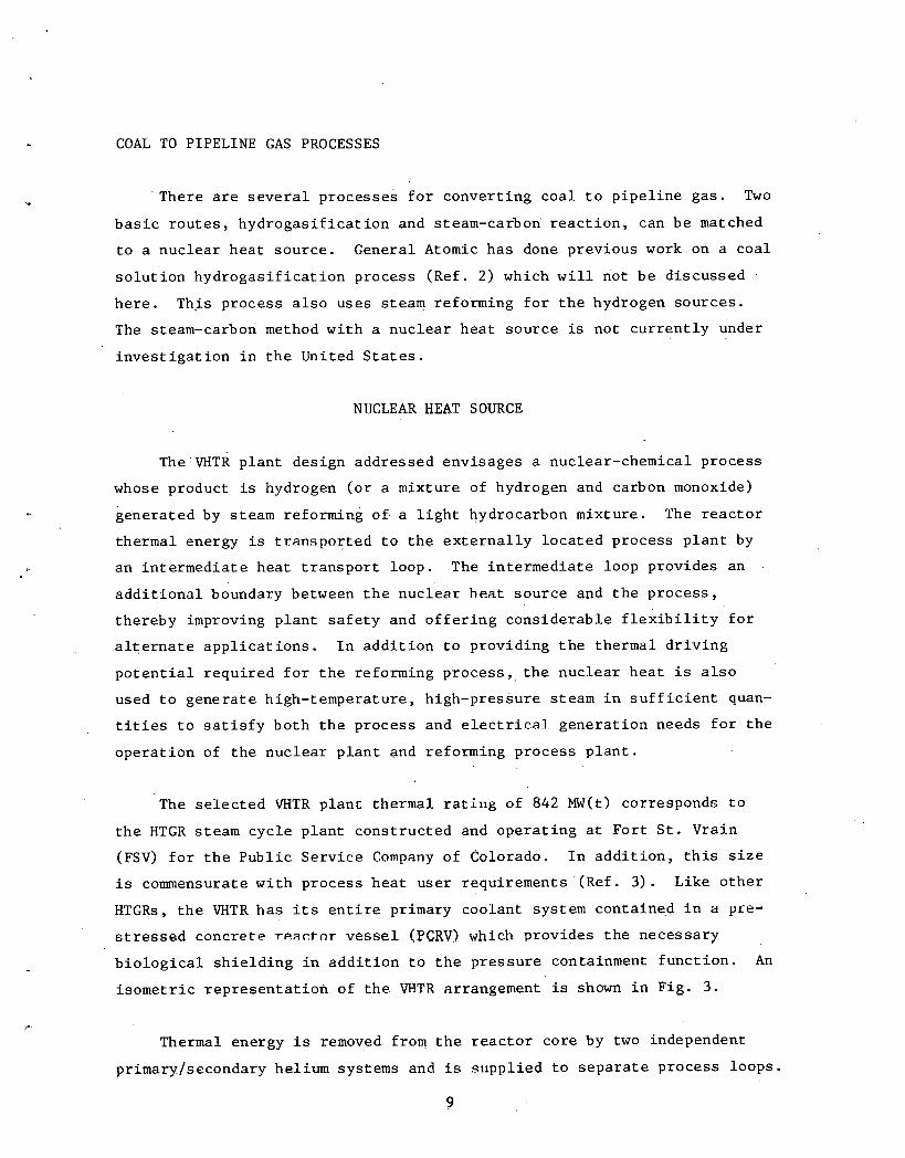
COAL TO PIPELINE GAS PROCESSES
' T h e r e a r e s e v e r a l p rocesses f o r conver t ing c o a l t o p i p e l i n e gas . Two
b a s i c r o u t e s , h y d r o g a s i f i c a t i o n and steam-carbon' r e a c t i o n , can be matched
t o a nuc l ea r hea t sou rce . General Atomic has done prev ious work on a coa l
s o l u t i o n hydrogasif i c a t i o n process (Ref. 2) which w i l l not be d i scussed
h e r e . This process a l s o uses steam refo'nning f o r t h e hydrogen sou rces .
The steam-carbon method w i t h a nuc l ea r h e a t sou rce is not c u r r e n t l y under
i n v e s t i g a t i o n i n t h e United S t a t e s .
NlJCLEAR HEAT SOURCE
T ~ ~ ' V H T R p l a n t des ign addressed envisages a nuclear-chemical p rocess
whose product is hydrogen ( o r a mixture of hydrogen and carbon monoxide)
genera ted by s team reforming of. a l i g h t hydrocarbon mixture . The r e a c t o r
thermal energy i s t r a n s p o r t e d t o t h e e x t e r n a l l y l o c a t e d process p l a n t by
an i n t e r m e d i a t e hea t t r a n s p o r t loop. The in t e rmed ia t e loop provides an
a d d i t i o n a l boundary between t h e nuc l ea r h e a t sou rce and t h e p roces s ,
thereby improving p l a n t s a f e t y and o f f e r i n g cons ide rab l e f l e x i b i l i t y f o r
a l t e r n a t e a p p l i c a t i o n s . I n a d d i t i o n t o provid ing t h e thermal d r i v i n g
p o t e n t i a l r equ i r ed f o r t h e reforming p r o c e s s , , t h e nuc l ea r h e a t i s a l s o
used t o gene ra t e high-temperature , high-pressure steam i n s u f f i c i e n t quan-
t i t i e s t o s a t i s f y bo th t h e process and e l e c t r i c a l gene ra t i on needs f o r t h e
ope ra t i on of t h e nuc l ea r p l a n t and reforming process p l a n t .
The s e l e c t e d WTR p l a n t thermal r a t i n g of 842 MW(t) corresponds t o
t h e HTGR steam c y c l e p l a n t cons t ruc t ed and o p e r a t i n g a t Fo r t S t . Vrain
(FSV) f o r t h e P u b l i c Se rv i ce Company of Colorado. I n a d d i t i o n , t h i s s i z e
i s commensurate w i t h process h e a t u se r requirements (Ref. 3 ) . Like o t h e r
HTGRs, t h e VHTR h a s i t s e n t i r e primary coolan t system conrained i n a pee-
~ t r e s s s d conc re t e rP.af.tnr v e s s e l (PCRV) which provides t h e necessary
b i o l o g i c a l s h i e l d i n g i n a d d i t i o n t o t h e p r e s s u r e containment f u n c t i o n . An
i s o m e t r i c r e p r e s e n t a t i o n of t h e VHTR arrangement is shown i n F ig . 3.
Thermal energy i s removed from t h e r e a c t o r core by two independent
primarp/secondary hel ium systems and i s supp l i ed t o s e p a r a t e process loops .

T h i s approach avoids t h e need t o s h u t down t h e e n t i r e p l a n t i n t h e event of
an upse t i n one of t h e . p r o c e s s t r a i n s and a l s o permits maintenance work t o
b e c a r r i e d out on an i s o l a t e d secondary loop dur ing p l a n t ope ra t ion . Three
independent shutdown loops have been provided, each wi th t h e c a p a b i l i t y of
f u l l - c o r e decay h e a t removal dur ing emergency condi t ions .
F igu re 4 p r e s e n t s t h e b a s i c flow diagram and gives t h e s t eady- s t a t e
o p e r a t i n g c o n d i t i o n s . The primary helium temperature of 950°C (1742°F) was
e s t a b l i s h e d t o meet t h e requirements of t h e chemical process wh i l e s t a y i n g
w i t h i n t h e s t r u c t u r a l l i m i t s of t h e Inconel 617 m a t e r i a l used i n t h e i n t e r -
mediate h e a t exchanger (IHX). Ma te r i a l s compa t ib i l i t y programs c u r r e n t l y
i n p rog res s w i l l have a s t r o n g bea r ing on whether t h e cor ros ion r e s i s t a n c e
of t h i s m a t e r i a l i s adequate a t t h i s temperature. The c u r r e n t work a t GA
is aimed a t a lower c o r e o u t l e t temperature - i n t h e range of 750" t o 850°C
(1390" t o 1560°F). These lower temperatures a r e more compatible w i th a
des ign t h a t could l e a d t o an e a r l i e r demonstrat ion p l a n t i n t h e United
S t a t e s . The p r e s s u r e l e v e l of 5 MPa (725 p s i a ) i s c o n s i s t e n t w i th
approaches followed i n t h e FSV design.
Each primary loop inc ludes an I H X , an e l e c t r i c motor dr iven primary
he l ium c i r c u l a t o r , and r e l a t e d ins t rumenta t ion and c o n t r o l s . The primary
coo lan t f lows downward through t h e r e a c t o r co re , where i t i s hea ted t o
950°C (1742°F). The h o t hel ium is c o l l e c t e d i n a plenum a r e a beneath t h e
core and manifolded t o t h e two I H X u n i t s s i t u a t e d i n s i d e c a v i t i e s bes ide .
t h e core . The primary hel ium f lows upward through t h e I H X c a v i t y , counter-
c u r r e n t l y t r a n s f e r r i n g h e a t t o the ' secondary hel. l .~m. The cooled primary
hel ium l e a v i n g each I H X is then ducted t o i ts r e s p e c t i v e c i r c u l a t o r , which
r e t u r n s i t t o t h e i n l e t plenum above t h e r e a c t o r core a t 475°C (887°F).
The secondary hel ium system ( o r secondary loop) t r a n s p o r t s thermal
energy from t h e I H X t o t h e process p l a n t . Because leakage w i t h i n t h e I H X
can ' r e s u l t i n . d i r e c t communication between t h e secondary and primary c i r -
c u i t s , t h e secondary helium p r e s s u r e 1 e v e l . i ~ s e t s l i g h t l y h ighe r than t h a t
i n t h e primary c i r c u i t . Th i s prevents p o s s i b l e leakage of t h e r e a i t o r .

C ~ R c u ~ ~ T o R - n
Fig. 3. HTGR-process heat source

PRIMARY SECONDARY HELIUM CIRCULATOR HELIUM CIRCULATOR 3910c
- - - - - - - - FEEDWATER
I I I
STEAM GENERATOR
I HTG R STEAM 5 1 0 ' ~ - 17.2 MPa I I CORE (950°F - 2500 PSIA)
I 842 MW(t) FEED
PRIMARY PROCESS HEAT EXCHANGER
I 341 KGIS (2.70 x lo6 LBIHR) L ----------,--,-,,,,,,, J
PCRV b EFFLUENT Fig. 4 . HTGR-process heat £.low diagram

he l ium i n t o t h e secondary sys tem. The secondary he l ium i s i n t e n t i o n a l l y
main ta ined a t a p r e s s u r e l e v e l n e a r t h e pr imary he l ium p r e s s u r e i n o r d e r
t o minimize t h e long-term l o a d i n g on t h e I H X , in. which t h e 'combination o f
h i g h t e m p e r a t u r e and m a t e r i a l l i m i t a t i o n s r e q u i r e s a near -p ressure -
b a l a n c e d o p e r a t i o n f o r s t r u c t u r a l i n t e g r i t y .
The two secondary he l ium l o o p s each c o n s i s t of an I H X , a r e f o r m e r , a
s team g e n e r a t o r , a secondary he l ium c i r c u l a t o r , and t h e r e l a t e d p i p i n g ,
v a l v e s , and i n s t r u m e n t a t i o n . During normal o p e r a t i o n secondary he l ium is
h e a t e d t o 89g°C (1650°F) i n t h e I H X and r o u t e d o u t s i d e t h e PCRV t o t h e
re fo rmer and t h e n to , t h e steam g e n e r a t o r , which e x t r a c t s t h e ' h e a t n e c e s s a r y
f o r t h e p r o c e s s and a u x i l i a r y power g e n e r a t i o n . The h o t he l ium t h e r m a l
energy i s s p l i t between t h e re fo rmer (52%) and s team g e n e r a t o r (48%) . Cool
he l ium is t h e n pumped back t o t h e I H X a t a t e m p e r a t u r e of 417OC (782OF) by
t h e secondary c i r c u l a t o r .
COMPONENT DESCRIPTION
PRESTRESSED CONCRETE REACTOR VESSEL
The PCRV i s a m u l t i c a v i t y p r e s s u r e v e s s e l which, t o g e t h e r w i t h l i n e r s
and p e n e t r a t i o n s , f u n c t i o n s a s t h e primary conta inment f o r t h e r e a c t o r c o r e
and t h e p r imary c o o l a n t system. The PCRV a l s o p r o v i d e s b i o l o g i c a l s h i e l d -
i n g around t h e c o r e and p r o v i d e s t h e n e c e s s a r y s t r u c t u r a l s u p p o r t f o r t h e
n u c l e a r h e a t s o u r c e sys tem. . It is c o n s t r u c t e d of h igh-s t . rength c o n c r e t e
r e i n f o r c e d w i t h c o n v e n t i o n a l r e i n f orcLng b a r s and p r e s t r e s s e d by two yos t-
t e n s i o n i n g sys tems , t h e l i n e a r p r e s t r e s s i n g system and t h e c i r c u m f e r e n t i a l
p r e s t r e s s i n g s y s t e l ~ t . The l i n e a r p r e s t r e s s i n g sys tem c o n s i s t s of i n d i v i d u a l
m u l t i s t r a n d tendons t o develop t h e v e r t i c a l p r e s t r e s s f o r t h e PCRV, and t h e
c i r c u m f e r e n t i a l p r e s t r e s s i n g sys tem employs w i r e wind ing around t h e circum-
f e r e n c e u f the PCRV t o p r o v i d c t h e r e q u i r e d r a d i a l p r e s t r e s s . A l l d a v i t i e s
and p e n e t r a t i o n s a r e l i n e d w i t h welded s t e e l l i n e r s which a c t a s imperme-
a b l e g a s - t i g h t membranes t o c o n t a i n t h e pr imary c o o l a n t . Th.e l i n e r s a r e
anchored by s t u d s welded t o t h e l i n e r s and embedded i n t h e c o n c r e t e .

Tab le 4 g i v e s t h e p e r t i n e n t des ign parameters a s s o c i a t e d w i t h t h e PCRV
and i t s c a v i t i e s .
THERMAL BARRIER
The thermal b a r r i e r , i n conjunct ion wi th t h e PCRV cool ing water sys-
tem, c o n t r o l s t h e tempera ture l e v e l s and g rad ien t s i n t h e PCRV and mini-
mizes h e a t l o s s e s from t h e primary coolant system. The thermal b a r r i e r
des ign i s d i r e c t l y based on t h e designs developed f o r t h e HTGR gas t u r b i n e
and s team c y c l e p l a n t s . It h a s been necessary t o upgrade t h e temperature
c a p a b i l i t i e s of c e r t a i n c l a s s e s of thermal b a r r i e r s f o r use i n t h e process .
h e a t r e a c t o r because of t h e more demanding temperature requirements . The
i n s u l a t i o n m a t e r i a l used i s f i b r o u s alumina and alumina s i l i c a . The
f i b e r s , i n t h e form of mats , a r e f i rmly he ld aga ins t t h e c a v i t y l i n e r s by
cover p l a t e s . Except i n t h e co re o u t l e t reg ion , m e t a l l i c p l a t e s of t h e
same m a t e r i a l s used i n HTGR steam cyc le p l a n t s a r e used. The VHTR core
o u t l e t gas tempera tures r e q u i r e nonmeta l l ics i n t h i s reg ion . A carbona-
ceous f i b e r - r e i n f orced cornposit e is be ing considered f o r t h e core o u t l e t
plenum s i d e w a l l and hot duct cover p 1 . a t . e ~ ; slip-rqst ceramic b l o s l c ~ of
fu sed alumina and fused s i l i c a a r e bGing considered f o r t h e .plenum f l o o r
cover p l a t e s . The high-temperature thermal b a r r i e r w i l l involve develop-
menta l work.
The thermal b a r r i e r t h i c k n e s s , cover p l a t e s i z e , and method of a t t a c h - '
ment t o t h e c a v i t y l i n e r va ry , depending on l o c a t i o n and r equ i r ed duty.
Thin m e t a l l i c s e a l s h e e t s and s l e e v e s a r e placed 'between t h e cover p l a t e s ,
t h e f a s t e n e r s , and t h e f i b r o u s i n s u l a t i o n t o minimize t h e l o s s of f i b e r s
i n t o t h e primary system and t h e f low 'o f coolant i n t o t h e f i b e r mats. The
o v e r a l l th ickness . of t h e thermal b a r r i e r ranges from 102 t o . 2 2 9 mm ( 4 t o
9 i n . ) depending on l o c a t i o n .
REACTOR CORE
The VHTR core is t h e same s i z e [842 MW(t)l and ope ra t e s a t t h e same . .
power d e n s i t y a s t h e FSV HTGR. I n a d d i t i o n , . t h e p r i sma t i c f u e l b lock
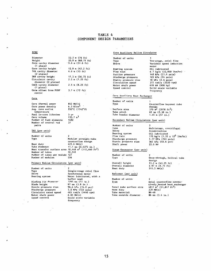
TABLE 4 COMPONENT DES IGN PARAMETERS
PCRV - Diameter Height Core cavity diameter
(1 place) Core cavity height IHX cavity diameter (2 places)
IHX cavity height Circulator cavity diameter (2 places)
CACS cavity diameter (1 place)
Core offset from PCRV center
23.2 m (76 ft) 20.9 m (68.75 ft) '9.6 m (31.6 ft)
12.9 m (42.2 ft) 4.6 m (15 ft)
17.3 m (56.75 ft) 2.2 m (7.25 ft)
2.5 m (8.25 ft)
3.7 m (12 ft)
Core - Core thermal power 842 MW(t) Core power density 6.3 w/cm3 Avg. core outlet 950°C (174Z°F)
temperature Fuel in-core lifetime 3 Yr Core volume 133.7 m3 Number of fuel elements 1482 Number of control rod 3 7 pairs
IHX (per unit)
Number of units 2 TYPC Modular straight-tube
counterflow design Heat duty 425.6 MW(t) Tube diameter 11.1 mm (0.4375 in.) Heat transfer surface area 10,448 m2 (112,460 ft2) Number of tubes 32,512 Number of tubes per module 127 Number of modules 256
Primarv Helium Circulators (oer unit)
Number of units Type Drive Bearing system
Bladin~ tip A i a m e r e r
Blade height Stacic pressure rise Discharge pressure . Circulator rated speed Motor shaft power Speed control
2 . Single-stage axial flow Synchronous motor Water lubricated, with a buffer seal 1795 mm (51 In.) 97 mm (3.8 in.) . 96.6 kPa (14.0 psi) 5.0 MPa (725 psia) 465 radls (4440 rpm) 6.85 MW(e) Solid state variable frequency
Core Auxiliary Helium Circulator
Number of units Type Drive
Bearing system Flow rate Suction pressure Discharge pressure Static prrauu.fr rise Circulation speed Motor shaft power Speed control
Cnre Allxi l.iary Heat Exchan~er
1 Two-stage, axial flow Variable speed induction motor Oil lubricated 6.7 kgls (53,000 lbmlhr) . 148 kPa (21.4 psia) 165 kPa (24 psia) 18 kPa (2.6 psia) 372 radls (3550 rpm) 670 kW (900 hp) Solid state variable freq~tancy
Number of units 1 Type Counterflow bayonet tube
design Surface area 370 m2 (3978 ft2) Tube pitch 60 mm (2.38 in.) Tube bundle diameter 1.45 m (57 in.)
Secondary Helium Circulators (per unit)
Number of units Type Drive Bearing system Flow rate Discharge pressure Static pressure rise Shaft power
2 Multistage, centrifugal Steam-turbine Oil lubricated 170 kgls (1.35 x 10' lbmlhr) 5.27 MPa (765 psia) 362 kPa (52.6 psi) 22.6 MW
Steam Generator (oer unit)
Number of units Type .
Overall height Overall diameter
2 Once-through, helical tube design 13.2 rn (43.25 ft) 2.97 m (9.75 ft)
Heat duty 215.5 MW(t)
Reformer (per unit)
Number of units 2 . T y ~ e Axial counterflow convec-
tively heated heat exchanger Total tube surfncc nrco 4817 m2 (51,847 ft2) Heat duty 219 MW(t) Tube material HK-40 Tube outside diameter . 86 mm (3.4 in.)

des' ign i s i d e n t i c a l t o t h e FSV design. The core c o n s i s t s of . v e r t i c a l
columns of hexagonal g r a p h i t e f u e l moderator elements and g r a p h i t e r e f l e c -
t o r b l o c k s gr'ouped i n t o a c y l i n d r i c a l a r r a y and supported by a g r a p h i t e
suppor t s t r u c t u r e . The co re i s d iv ided i n t o 37 f u e l r eg ions , each con-
s i s t i n g of a c e n t r a l f u e l c o n t r o l element column wi th s tandard surrounding
columns. Th i s arrangement con ta ins 210 s t anda rd f u e l columns and 37 con-
t r o 1 , ' f u e l columns. Each column c o n s i s t s of s i x f u e l e lements , f o r a t o t a l
'o f -1482 elements i n t h e co re . The coolant flow r a t e through each f u e l
'. r e g i o n is c o n t r o l l e d by a v a r i a b l e o r i f i c e mechanism a t each reg ion i n l e t .
The f i s s i l e f u e l m a t e r i a l is TRISO-coated uranium ca rb ide , and t h e
f e r t i l e m a t e r i a l i s BISO-coated thorium oxide. The uranium and thorium
p a r t i c l e s a r e coated wi th l a y e r s of p y r o l y t i c carbon (and s i l i c o n carb ide
f o r t h e uranium p a r t i c l e s ) and bonded i n t o f u e l rods w i t h i n t h e hexagonal
g r a p h i t e e lements . The p a r t i c l e coa t ings pr.ovide t h e primary b a r r i e r f o r
f i s s i o n product r e t e n t i o n . E i t h e r h i g h l y enr iched uranium (HEU) o r
medium-enriched uranium '(MEU) cores a r e poss ib l e . The b a s i c s t r u c t u r a l
m a t e r i a l of t h e c o r e is nuclear-grade g r a p h i t e machined i n t h e form of
hexagonal b locks . These b locks a l s o s e r v e as t h e moderator and hea t t r a n s -
f e r medium between f u e l and coo lan t .
The 3-year f u e l c y c l e w i t h annual r e f u e l i n g of one t h i r d of the. core
shou ld reduce t h e e f f e c t s of f u e l age d i f f e r e n c e s i n t h e c o r e by minimizing
t h e . l o c a l power peaks i n t h e core , t h u s lowering peak f u e l tempera tures ,
neu t ron exposure, and consequent f i s s i o n product r e l e a s e . Design requi re -
ments f o r y i e l d i n g low f u e l p a r t i c l e f a i l u r e f r a c t i o n s , low f i s s i o n product
r e l e a s e , and- low g r a p h i t e b lock s t r e s s l e v e l s can t h e r e f o r e be s a t i s f a c t o -
r i l y met f o r t h e VHTR.
INTERMEDIATE HEAT EXCHANGER
The I H X i s a nuclear-grade s a f e t y clas's component which t r a n s f e r s t h e
h e a t from t h e primary hel ium c i r . c u i t t o t h e secondary hel ium c i r c u i t d u r i n g '
normal ope ra t ion a n d - i s a3so used t o remove hea t dur ing emergency core
cool ing . Th i s component h a s been designed a s a modu1arize.d s t r a i g h t - t u b e
16

counterflow hea t exchanger t o o b t a i n ( 1) geometric h e a t exchanger propor-
t i o n s most cons i s t en t w i t h t h e PCRV envelope, ( 2 ) minimum metal temperature
g r a d i e n t s , ( 3 ) reduced hel ium p res su re l o s s requirements , and (4) minimum
p o t e n t i a l f o r flow-induced tube v i b r a t i o n s . The design i s s i m i l a r t o t h a t
of helium-to-helium hea t exchangers used i n t h e HTGR gas t u r b i n e p l a n t .
Table 4 gives p e r t i n e n t design d a t a f o r t h e I H X . Although normal ope ra t ion
i s i n a near-pressure-ba1,anced cond i t i on , t h e design b a s i s i s p red ica t ed on
t h e l o s s of t h e secondary loop p re s su re p u t t i n g t h e tubes i n t o compression.
The cu r ren t s e l e c t i o n of tub ing m a t e r i a l i s Inconel 617. An ex tens ive
high-temperature m a t e r i a l s program i s i n progress t o o b t a i n high-tempe.rature
da t a f o r t h e p o t e n t i a l m a t e r i a l s i n t h i s a p p l i c a t i o n . The m a t e r i a l se3.e~- ;
t i o n and design of t h e I H X . r e p r e s e n t . a s u b s t a n t i a l t e c h n i c a l development
e f f o r t .
HELIUM CIRCULATORS
Axial and c e n t r i f u g a l flow c i r c u l a t o r s a r e used t o pump t h e helium i n
t h e VHTR primary and secondary helium loops , r e s p e c t i v e l y . With t h e pres-
e n t loop arrangement, e l e c t r i c motors w i th v a r i a b l e frequency c o n t r o l a r e
used t o power t h e primary loop c i r c u l a t o r s and steam t u r b i n e s a r e used t o
d r i v e t h e secondary loop c i r c u l a t o r s . Safe ty c l a s s pony motors on t h e
primary helium c i r c u l a t o r s , i n a d d i t i o n t o t h e main motors, and s a f e t y
c l a s s electr ic-motor-driven c i r c u l a t o r s i n t h e secondary loops provide
hel ium c i r c u l a t i o n - f o r emergency core cool ing . Table 4 g ives a d d i t i o n a l
design information f o r t h e primary, secondary, and a u x i l i a r y c i r c u l a t o r s .
REFORMERS '
The steam-methane reformer t r a n s f e r s t h e hea t from t h e helium loop t o
t h e reformer feeds tock i n t h e presence of a n i c k e l c a t a l y s t . It i s , i n
e f f e c t , an a x i a l counterflow convect'ive h e a t exchanger, . b u t wi th space
provided on t h e tube s i d e f o r t h e i n c l u s i o n of t h e . c a t a l y s t m a t e r i a l .
Many d i f f e r e n t concepts which appear t o s a t i s f y b a s i c reformer
requirements 8 r e pnss ih l e . However, t h e design considered i n t h i s paper

i s a concept which has been used i n t h e . f o s s i 1 - f i r e d reforming indus t ry f o r
many y e a r s , with v a r i a t i o n s r equ i r ed f o r adap ta t ion t o convect ive hea t ing .
This concept u t i l i z e s a shell-and-tube hea t exchanger which has. tubes l a r g e
enough t o con ta in t h e c a t a l y s t m a t e r i a l i n s t acked p a r t i c l e bed form. The
f e e d s t o c k is in t roduced on t h e tube s i d e of t h e hea t exchanger and flows
over t h e c a t a l y s t . p a r t i c l e s w h i l e be ing hea ted by t h e tube w a l l s . The.con-
v e r s i o n r e a c t i o n . t a k e s p l ace dur ing passage through t h e bed , r e q u i r i n g cha t
h e a t be supp l i ed t o t h e tubes over t h e e n t i r e a c t i v e l e n g t h . I n f o s s i l -
f i r e d reformers t h i s h e a t i npu t is supp l i ed by means of r a d i a n t energy from
many f u e l bu rne r s o r gas j e t s l oca t ed ad jacen t t o a row of c a t a l y s t t ubes .
To adapt t h i s concept t o a secoridary loop convect ive h e a t sou rce , t h e tubes
a r e grouped toge the r t o form a gas-to-gas tube-and-shell hea t exchanger.
The h o t se'condary hel ium is in t roduced on t h e s h e l l s i d e a t t h e hot ' end of
t h e c a t a l y s t t u b e s , flows counter t o t h e product gas around t h e tubes , and
i s d ischarged a t t h e co ld end.
STEAM GENERATORS
The s team generator , is s i m i l a r t o t h e HTGR steam c y c l e steam genera tor
i n bundle s i z e a n d . b a s i c des ign ; both a r e v e r t i c a l , uph i l l -bo i l i ng , once-
through h e l i c a l - t u b e gene ra to r s . For t h e VHTR, t h e bundles a r e i n s t a l l e d
i n i n t e r n a l l y i n s u l a t e d s t e e l p re s su re v e s s e l s which a r e l oca t ed i n t h e
secondary loop and t h e r e f o r e a r e not r equ i r ed t o be designed a s an ASME
Code, S e c t i o n 111, Class 1 component.
PLANT SAFETY AND EMERGENCY CORE COOLING
The VHTR inco rpora t e s a l l of t h e inhe ren t s a f e t y c h a r a c t e r i s t i c s of
t h e HTGR power p l a n t s . These inc lude l o w r e a c t o r power d e n s i t y , high core
h e a t c a p a c i t y , 'use of ceramic m a t e r i a l s f o r t h e core and' moderator,
s ing le-phase r e a c t o r c o o l a n t , and employment of a PCRV. I n a d d i t i o n ,
'engineered s a f e t y f e a t u r e s a r e provided t o .reduce t h e p r o b a b i l i t y and
m i t i g a t e t h e consequences of acc iden t s . These inc lude redundant means
f o r emergency t o r e cool ing and p rov i s ions f o r containment of r a d i o a c t i v e
r e l e a s e s .

The main core coolant loops have s a f e t y c l a s s components t o provide
emergency core cool ing c a p a b i l i t y . I n a d d i t i o n , a diverse-design s a f e t y . .
c l a s s core a u x i l i a r y cool ing loop is provided. One hundred percent shut -
down core cool ing c a p a b i l i t y can b e provided by any one of t h e s e t h r e e
loops , wi th t h e r e a c t o r e i t h e r p re s su r i zed o r depressur ized . The r e a c t o r
containment b u i l d i n g conta ins r e l e a s e s from any pos tu l a t ed pr imary .coolant
dep res su r i za t ion acc iden t s .
BALANCE OF REACTOR PLANT
. . Figure 5 shows a conceptual p l an t p l o t arrangement. The p l o t i s
arranged t o b e compatible with a twin r e a c t o r ' p l an t i n s t a l l a t i o n us ing
common f u e l handl ing and s t o r a g e f a c i l i t i e s . Reactor a u x i l i a r y s t r u c t u r e s
a r e arranged s i m i l a r t o cu r r en t HTGR power p l a n t concepts . A minimum ., .
s e p a r a t i o n d i s t a n c e of 61 m (200 f t ) is maintained between s a f e t y - r e l a t e d
r e a c t o r p l a n t s t r u c t u r e s . and the reformers i n t h e . secondary helium loops
t o provide p r o t e c t i o n a g a i n s t p o s s i b l e f a i l , ~ ~ r e s i n t h e process p l a n t . A
s i m i l a r s e p a r a t i o n i s maintained between t h e reformers and o t h e r equipment
i n ad j acen t process p l a n t t r a i n s .
The secondary helium c i r c u l a t o r s and turb ine-genera tors a r e l oca t ed
i n a b u i l d i n g near t h e reformers and steam gene ra to r s . Equipment i tems
r equ i r ed f o r s a f e r e a c t o r ope ra t ion and shutdown a r e l oca t ed i n s a f e t y
c l a s s p r o t e c t i v e b u i l d i n g s near t h e r e a c t o r containment. Secondary helium
containment p ip ing pene t r a t ions and i s o l a t i o n va lves a r e l o c a t e d i n pro-
t e c t i v e enc losures a t t ached t o t h e containment. "Z"-shaped bends i n t h e
secondary helium pipes provide f o r thermal expansions between t h e contain-
ment and process p l an t equipment.
The design of r e a c t o r a u x i l i a r y systems is very s i m i l a r t o t h a t fo r '
t h e HTGR power p l a n t s , except f o r a d d i t i o n a l f a c i l i t i e s f o r hel ium handl ing
and p u r i f i c a t i o n a s s o c i a t e d wi th t h e ' secondary helium loops. The Nuclear
Is land inc ludes t h e r e a c t o r s e r v i c e b u i l d i n g , which conta ins equipment f o r
f u e l hand l ing and o t h e r r e a c t o r support ope ra t ions ; t h e f u e l s t o r a g e bui ld-
i ng , which inc ludes a h o t s e r v i c e f a c i l i t y and f11el. sh ipping equipment; t h e

A -TURBINE GENERATORS
B - STEAM GENERATORS '
C -SECONDARY HELIUM CIRCULATORS
D - REFORMER E -ULTIMATE HEATSINK BUILDINGS
F - REACTOR CONTAINMENT G - REACTOR UNlT 1 H - CONTROL BUILDING I - FUEL STORAGE
J - REACTOR SERVICE K -ACCESS BUILDING L - FUTURE REACTOR UNlT
M - GUARD STATION N -SERVICE &ADMINISTRATION BUILDING
0 - PARKING
t - SCALE,
6 0 M -
F i g . 5. Twin 842-MW(~); HTGB-process heat plot plan

c o n t r o l and d i e se l -gene ra to r b u i l d i n g ; t h e u l t i m a t e hea t s i n k b u i l d i n g s ,
which house equipment f o r .emergency co re coo l ing h e a t r e j e c t i o n ; and t h e
access c o n t r o l b u i l d i n g .
PLANT DESIGN AND PERFORMANCE CODE
A s p a r t of t h e development of t h e nuc l ea r p rocess h e a t work, a com-
p u t e r model of t h e n u c l e a r h e a t source and t h e a s s o c i a t e d proc;ss p l a n t is
under.deve1opment. Th i s Process Heat Reactor Evalua t ion and Design (PHRED)
code w i l l b e a b l e t o :
1 . Ca l cu l a t e t h e complete mass flow and h e a t ba l ance f o r t h e r e a c t o r
p l a n t f o r a wide v a r i e t y of independent v a r i a b l e s , e. g. , core
o u t l e t t empera ture , primary loop p r e s s u r e , p rocess tempera ture .
2 . Spec i fy design ope ra t i ng cond i t i ons f o r a l l major components and
c a l c u l a t e t h e s i z e of t h e componemts based on t h e i r performance
requirements , e . g . , IHX, helium c i r c u l a t o r , steam gene ra to r , PCRV.
. 3 . Calcu la t e t h e c a p i t a l and ope ra t i ng c o s t s of t h e e n t i r e nuc l ea r
h e a t sou rce and a s s o c i a t e d process p l a n t .
4 . Couple t o any a v a i l a b l e mu l t i -va r i ab l e d i r e c t s ea rch op t imiza t ion
program f o r system op t imiza t ion s t u d i e s .
The program is des igned ' s0 t h a t it is capable of running a series of
ca se s where each case is de'fined by ' a set of va lues f o r t h e independent
des ign v a r i a b l e s (IDVs) , and t h e s e val.ues are inpu t by t h e program u s e r .
The program ope ra t e s i n a base c a s e - a l t e r n a t e c a s e mode. A b a s e ca se , o r
r e f e r e n c e des ign p l a n t , i s def ined f o r t h e program by s t o r e d inpu t d a t a
descr ib ' ing t h e des ign , performance, and c u s ~ of the r e f c r c n c c p l a n t . An
a l t e r n a t e ca se p l a n t i s then def ined by e x e r c i s i n g t h e p l a n t model w i t h i n
t h e program using' va lues of t h e I D V s which are d i f f e r e n t from t h e b a s e
c a s e va lues . A l is t of t h e 52 I D V s a v a i l a b l e t o t h e u se r 2s shown i n
Table 5.

TABLE 5 VALUES OF INDEPENDENT DESIGN VARIABLES
F A X I M U M P R I M A R Y H E L I U H P R E S S U R E P L b C T O R T H E R M A L P O U E R , P C A C T O Q I N L E T T E P P E R A T U R E . R L A C T O R O U T L E T T E M P E R A T U Q E P E h C T O R CORE DIAMETER P L A C T O R C O P E H E I G H T T O P R E F L E C T O R T H I C K N E S S S I D E R E F L E C T O R T H I C H N E S S R O T T O H R E F L E C T O R T H I C R N E S S COQE C O O L A N T H O L F D I A M r T E R C V R E H O L E P A T T E R N P I T C H CORE C 4 R . B O N / T H O R I b M R ' A T I O
I N T E R M E D I A T E H E A T E X C f i V I T V D I A M E T E R Q E P C T O R O U T L E T DUCT D I 4 M E T E R I N T E R H E A T EX O U T L E T D U C T D I 4 M E T E R C I R C U L A T O R C A V I T Y . D I A M E T E R . R E A C T O R I N L E T ' DUCT D I A M E T E R NUMBER O F C A C S L O O P S I Y THE P C R V
N U M B E R O F I N T E R M E D I A T E H E A T E X C H A N G E R S I N T E R H E A T EX S E C O N D 4 R V I N L E T TEMP I N T E R H E A T EX S E C O N D A R Y O U T L E T TEMP I N T E R M E D I A T E H E A T E X T U B E OUTER. D I A I N T E R H E A T EX T U R E P I T C H / D I A M E T E R R A T I O T M T E R H E A T EX C E N T R A L D U C T O U T E R O I A
M A X I M U M S E C O N D A R Y H E L I U W P R E S S U R E R C I C T O R - TO..RErORN!LR S E P A V A T I O N S E C O N D A R Y P I P I N G H O T - L € G OUTER 0 1 A S E C O N D A R Y P I P I N G C O L D - L E G O U T E 2 C I A H O T - L E G T H F R M A L B A R R I E Q T H I C K N E S S
NUMBER OF R E F O R M E R S R E F O R M E R S T E A M / M E T H A N E R A T I O R E F O R M E R P R O C E S S O U T L E T P R E S S U R E R E F O R M E R P R O C E S S O U T L E T T E Y P E R A T U R E R E F O R H E R T U B E O U T E R D I A M E T E R REFORMER. T U B E P I T C H / O I A M E T E R R A T I O '
R E F O R M E R . T O T A L NUMBER 9F T U B E S R E F O R M E R C A T A L Y S T P A R T I C L E D I A R E T E P
NUMBER OF S T E A M G E N E R A T O R S S T E A M G E N S T E A M O U T L E T P R E S S U R E S T F d M GEN S T E A w O U T L E T T E M P E R A T U R E S T E A M GEN E E S l T U B E O U T E R D I A M E T E R S T E A M GEN E E S l T U B E .WALL T H I C K N E S S S T F A M GEN E E S l T P A N S P I T C H / D I A R A T I O S T F A M GEN E E S 1 L O N G 1 P I T C H / D I A R A T I O S T C A M GEN S Z T U B E O U T E R P I A M F T E R S T E A M GEN S Z T U B E M A L L T H I C K N E S S S T F A M GEN S Z L O N G 1 P I T C H / D I A R A T I O S T E A M GEN T O T A L NUMBER O F T U B E S 'STFAM GEN N U M 5 E R OF T U B E L A V E R S 5 G C E N T R A L DUCT OU,TER D I A R E T E R
C O G E N E R A T E C E L E C T R I C P O Y E R O U T P U T A M R I E N T T E M P E R A T U R E

The top- leve l l o g i c is shown i n F ig . 6 . The major i t e r a t i o n loop
shown on t h e diagram is t h e i t e r a t i v e s o l u t i o n r equ i r ed t o ach ieve an
t> energy and mass ba l ance over a l l t h e flow and energy pa ths i n . t h e p l a n t .
The p l a n t des ign used f o r t h e r e f e r e n c e des ign i s t h a t de sc r ibed i n
t h i s paper and shown diagrammatical ly i n F ig . 7. There a r e fou r i n t e r a c t -
i n g f l u i d loops t h a t must be so lved i t e r a t i v e l y i n o rde r t o complete t h e
.mass and h e a t ba l ance : primary helium., secondary . . hel ium, steam c y c l e , and
process cyc le . I n o rde r t o keep t h e program a s f l e x i b l e a s p o s s i b l e and
t o match t h e r e a c t o r program w i t h d i f f e r e n t p rocess p l a n t s , t h e process
p l a n t i s handled s e p a r a t e l y and methods of j o i n i n g t h e two t o g e t h e r have
been developed. The r e f e r ence process p l a n t i s steam-methane reforming
and has been modeled us ing t h e commercially a v a i l a b l e process des ign code
DESIGN/2000 developed by the 'memsha re Corporat ion (Ref. 4 ) . The d a t a
ob ta ined a r e t r a n s c r i b e d t o supply a d a t a t a b l e w i t h i n t h e pa rame t r i c
design program. When programmed f o r a p a r t i c u l a r p roces s , DESIGN/2000 has
t h e c a p a b i l i t y of i t e r a t i v e l y s o l v i n g f o r a l l f l u i d flow s t reams, s i z i n g
process equipment, and e s t a b l i s h i n g performance d a t a . The r e s u l t s of t h i s
code a r e a l s o used a s input t o e s t a b l i s h t h e cos t of t h e process p l a n t .
HEAT EXCHANGERS
Since t h e h e a t exchangers a r e a t t h e loop t n t e r s e c t i o n s , t h e modeling
of t h e s e units is very impor tan t . These models a r e descr ibed b r i e f l y below.
1nte .nnediat e Heat Exchanger
The I H X h e a t t r a n s f e r i s computed us ing a s i n g l e mode and averaged
hel ium p r o p e r t i e s . Previous s t u d i e s have shown e x c e l l e n t agreement
between t h i s s imple approach and more complex ana lyszs performed by i ter-
atlrlg a luug ~ 1 1 e le~lgL11 uf Llit Liiiidlt. Pa r a givcn o c t of ope ra t i ng con-
d i t i o n s and I H X f r o n t a l geometry, t h e model des igns a counterf low tubu la r ,
helium-to-helium hea t exchanger based on t h e mechanical l ayou t e s t a b l i s h e d

INPUT n
1 YES
REMAINDER OF SIZING
COMPUTATION + Fig. 6. Top level logic diagram for the PHRED computer program

HOUSE LOAD COGENERATED POWER
CIRCULATOR
I HX REACTOR
PRIMARY HELIUM STEAM LOOP METHANE
4
I PROCESS PROCESS LOOP PLANT
REF0 RMER
SECONDARY HELIUM
HYDROGEN
Fig. 7. Schematic loop arrangement for VHTR hydrogen production process plant

f o r t h e r e f e r e n c e des ign . Th i s hea t exchanger design process i nc ludes t h e
fo l lowing de termina t ions :
1 . Thermal s i z i n g .
2 . Primary and secondary s i d e p re s su re l o s s e s ( i nc lud ing paras it i c s ) .
3 . Tube m a t e r i a l s e l e c t i o n (Incoloy 800H o r Inconel 617) wi th t h e
op t ion of s i t i n g a b i m e t a l l i c weld a t a r e f e rence metal
t empera ture .
4 . S t r u c t u r a l t h i c k n e s s e s of c y l i n d r i c a l p re s su re p a r t s ( shor t - te rm.
c o m p r e s s i v e ~ l o a d s , long-term t e n s i l e loads', and p r a c t i c a l handl ing
th i cknesses cons idered i n t h e s e l e c t ion process) .
5. PCRV c a v i t y envelope requirements ( i nc lud ing p a r a s i t i c he ight
a l l o c a t i o n s ) .
6. Weight breakdown of I H X c o n s t i t u e n t p a r t s .
7. Enhanced s u r f a c e geometry op t ion .
A f lowsheet d e s c r i p t i o n is g iven i n F ig . 8. Items 3 and 4 above a r e t h e
most .important f e a t u r e s of t h e I H X model because t h e m a t e r i a l t y p e and
q u a n t i t y of I H X t u b i n g a r e a n important VHTR economic cons idera t i on .
' . Since t h e I H X t ub ing cos t i s roughly p ropor t iona l t o t h e t u b e wall
t h i c k n e s s , cons ide rab le a t t e n t i o n was given t o developing s imple , closed-
form c o r r e l a t i o n s f o r computing tube w a l l t h i ckness c o n s i s t e n t wi th ' t h e
procedures given i n S e c t i o n I1 of t h e ASME B o i l e r and Pressure Vessel code.
Th i s e n t a i l e d e x t r a p o l a t i n g a v a i l a b l e t e s t d a t a f o r t h e ' o p e r a t i n g
t empera tu re lma te r i a l regimes n o t c o v e r e d ' i n t h e Code. No a d d i t i o n a l w a l l
t h i c k n e s s al lowance c a l c u l a t i o n s a r e b u i l t i n t o t h e IHX model a t t h i s time.
I n s t e a d , t h e model can 'accommodate a s p e c i f i e d th i ckness allowance a s an

INPUT
'7' COMPUTE TUBE SIDE FLOW, TUBE SIDE INLET DENSITY,
LEAD TUBE DIAMETERS .
GUESS THERMAL CONDUCTANCE RATIO 4
IN H. T. MATRIX
, COMPUTE STRUCTURE
COMPUTE THERMAL
THICKNESSES CONDUCTANCE
AND MATERIAL RATIO IN H. T. MATRIX
COMPUTE THERMAL SIZE AND LOCATE BIMETALLIC WELD
I
GUESS OUTLET PRESSURES
COMPUTE PCRV ENVELOPE
COMPUTE OUTLET PRESSURES
COMPUTE CONSTITUENT
WEIGHTS
GUESSES WITH
F i g . 8. IHX computer model flowsheec
2 7 . .

i n p u t I D V which is added t o t h e c a l c u l a t e d s t r u c t u r a l t h i cknes s p r i o r t o
t he rma l s i z i n g o p e r a t i o n s .
Work t o r e f i n e t h e IHX,model i s con t inu ing , and i t i s expected t h a t
t h i s upgrading w i l l con t inue a s more m a t e r i a l s ' d a t a and .design technology
improvements become a v a i l a b l e . . .
Reformer
The reformer model u t i l i z e s a reformer s i z i n g program o r i g i n a l l y
developed by Los Alamos S c i e n t i f i c Laboratory. This model w i l l determine
t h e re former t ube l e n g t h , h e a t du ty , p rocess o u t l e t composi t ion, and
he l ium o u t l e t c o n d i t i o n s when given t h e fo l lowing s e t of I D V s :
1 . Tube ' i n s i d e d iameter . 2 . Tube p i t c h l d i a m e t e r r a t i o .
3 . Steamlmethane r a t i o .
4 . Methane-s t eam i n l e t t empera ture . 5 . Methane-st eam ou t l e t t empera ture . 6 . Methane-steam o u t l e t p r e s s u r e .
7 . C a t a l y s t d i ame te r .
Th i s model ' c a l c u l a t e s , f o r each increment of l eng th a long t h e t ube ,
t h e h e l i u m . s i d e h e a t t r a n s f e r c o e f f i c i e n t , p rocess s i d e hea.t t r a n s f e r
c o e f f i c i e n t , and tempera tures a s w e l l a s t h e re'forming r e a c t i o n r a t e .
T h i s re former model has, a l s o been adapted t o o p e r a t e a s part of t h e process
des ign model w i t h i n DESIGN/2000 (Ref. 4 ) , s o both t h e secondary loop model
and process model u t i l i z e t h e same reformer model.
Steam Generator
The steam, gene ra to r model is taken £?om t h e s t a n d a r d s team gene ra to r
de s ign computer program used a t General Atomic, bu t i t has been reworked ., , . .
s o t h a t i t r e q u i r e s l e s s computer run t i m e t han i t s s t anda rd v e r s i o n . The

tube bundle con f igu ra t i on used i s a h e l i c a l c o i l des ign . The I D V s used t o
d e f i n e t h e steam gene ra to r design a r e :
1 . I nne r diameter of t h e o u t e r bundle shroud.
2 . Outer diameter of t h e i nne r bundle shroud.
3 . Number of t ube rows.
4 . Longi tud ina l t ube p i t c h .
5. stress margin (determines t ube diameter) . .6. O u t l e t steam temperature .
7 . Ou t l e t s team p re s su re .
The computations a r e performed over smal l increments of t h e l eng th of
t h e bundle , from t h e ho t end toward . the co ld end, and t h e bundle is d iv ided
i n t o t h r e e main s e c t i o n s : economiz.er, evapora to r , and supe rhea t e r . The
length of each s e c t i o n of t h e bundle and t h e a s s o c i a t e d p re s su re drops : a r e
t h e major dependent v a r i a b l e s computed by t h e model.
INTERACTION OF PROCESS PLANT AND NUCLEAR PLANT
The major l i n k between t h e nuc l ea r p l a n t and t h e process p l a n t i s t h e
steam gene ra to r and t h e re former . T.he s team gene ra to r i s t h e key i t e m i n
coupl ing t h e two.systems. The steam produced i n t h e steam gene ra to r has
t h r e e uses . It provides t h e steam which i s mixed wi th methane t o form t h e
reformer feed ; i t provides h e a t and power (from tu rbogene ra to r s e t s ) f o r
t h e process p l a n t ; and i t provides a - s e p a r a t e flow t o d r i v e t h e turbogener-
a t o r f o r t h e house l oad ( i nc lud ing t h e primary helium c i r c u l a t o r motors)
and t o power t h e t u r b i n e s which d r i v e t h e secondary helium c i r c u l a t o r s .
I f t h e steam produced by t h e steam gene ra to r s is no t s u f f i c i e n t t o supply
a l l t h r e e u se s , t hen t h e i t e r a t i o n v a r i a b l e (methane mass flow r a t e ) .must
be reduced t o ach ieve t h e o v e r a l l p l a n t energy and mass ba lance . The
o v c r a l l cncrgy and mass ba lancc i s obtained by us ing a l i n e a r f r a c t i o n a l
s ecan t method t o r e v i s e t h e es t imated methane mass flow r a t e f o r each
i t e r a t i o n u n t i l convergence is rea&ed.

The l o g i c s t r u c t u r e of t h e program requ i r ed t o model t h e s team reform-
i n g of methane t o produce hydrogen i s extremely complex. Th i s process h a s
been modeled s e p a r a t e l y i n DESIGN/2000. The complexity, s i z e , and computer
running t i m e of t h i s program prec lude i t s i n c o r p o r a t i o n i n t o PHRED a s a
s u b r o u t i n e t o model t h e p roces s p l a n t . Therefore , t h e process p l a n t is
modeled i n PHRED by a series of d a t a t a b l e s and cu rve - f i t sub rou t ines
which r e p r e s e n t t h e r e s u l t s of a s e r i e s of independent runs of t h e DESIGN/
2000 program. The e x t e n t of t h i s d a t a w i l l b e expanded a s a d d i t i o n a l
p roces s i n fo rma t ion becomes a v a i l a b l e and a s s t u d i e s us ing PHRED i n d i c a t e
a r e a s of de s ign which improve t h e o v e r a l l p l a n t economics.
1 . The c u r r e n t U.S. energy p i c t u r e p r 0 v i d e s . a b r i g h t f u t u r e f o r syn-
f u e l programs based on c o a l . P,ro.cess development p lans a r e be ing
f i rmed up, and demonstrat ion s i z e p l a n t s should be s t a r t e d i n t h e
n e a r f u t u r e .
2 . Current a n a l y s i s of t h e i n c l u s i o n of HTGRs i n t h e syn fue l program
shows a major advantage i n c o a l sav ings and environmental impact
b u t no p a r t i c u l a r c o s t advantage a t p r e sen t U.S. c o a l p r i c e s .
3 . A conceptua l de s ign f o r t h e nuc l ea r p rocess hea t p l a n t a t 950°C
(1742°F) c o r e o u t l e t h a s been developed based on t h e General
Atomic s team c y c l e and gas t u r b i n e work. For some a p p l i c a t i o n s ,
no t ab ly c o a l g a s i f i c a t i o n by steam-carbon r e a c t i o n of bituminous
c o a l and thermochemical w a t e r s p l i t t i n g , t h e 950°C (1742OF) temper-
a t u r e may be r equ i r ed . For steam-methane reforming, lower temper-
a t u r e s are s t i l l e f f i c i e n t and a r e be ing examined.
4 . The PHRED code c u r r e n t l y under development w i l l b e a powerful
t o o l i n e s t a b l i s h i n g t h e o v e r a l l system parameters f o r an o p t i -
. mized n u c l e a r h e a t source-chemical p roces s p l a n t .

REFERENCES
1 . "Environmental A n a l y s i s of S y n t h e t i c L i q u i d F u e l s , " A s s i s t a n t Secre-
t a r y f o r Environment, O f f i c e of Technology Impac t s , J u l y 12, 1979.
2 . Wi l l i ams , J . , et a l . , "Coal S o l u t i o n G a s i f i c a t i o n With a Nuc lea r Heat
Source ," p r e s e n t e d a t t h e ASME J o i n t Power Genera t ion Conference,
P o r t l a n d , Oregon, September 30, 1975. .
3. "Nuclear P r o c e s s Heat (VHTR) Commercia l iza t ion Study ," DOE Report
GA-A14668, General Atomic Company, December 1977.
4 . "DESIGN/2000. Chemshare P r o c e s s S i m u l a t i o n , I ' Chemshare C o r p o r a t i o n ,
1978.