butterfly valve - mirab comirabco.net/en/app_files/public/64a2f069-be25-4701-a7a3-478c87f09c...6...
TRANSCRIPT

R
Butterfly Valve

R
Butterfly Valve
TABLE OF CONTENT
Title
1 Product description and fields of applications
2 Design specification and technical data
2-1 Butterfly Valve
2-2 AUMA Gearbox
2-2-1 Worm gearboxes on butterfly valve
2-2-2 Setup and Operation
3-Selection of Pressure Containing and Controlling Parts Material 3-1 Selection of Valve Trim Material 3-2 Selection of valve nominal size (DN) and pressure (PN)
4-Installation Dimensions
4-1 Manually Operated Butterfly valve
4-2 Electric Actuator Butterfly valve
5-Optional Body Configurations
5-1 Long Pattern
5-2 Short Pattern
6 Recommended Practice for valve installation
7 Initial start up
8 Operation
9 Maintenance

R
Butterfly Valve
Butterfly Valves Flange Type (BVF)
1 Product description and fields of applications
Mirab co. Butterfly valves are used for fluids such as raw water, drinking water, waste water, compressed air and neutral gases at temperatures up to 70° C and are designed with flow optimization to ensure minimum effects on the flow when the valve is open. This ensures that the whole system can be operated, with the lowest possible head loss coefficient. The valve discs of Mirab co. butterfly valves are supported in the body with double eccentricity and Low friction bearings provide maximum radial support for higher shaft loads. The PTFE lined bearings having low coefficient of friction minimizes operating torque and reduces actuator size. They are slip-in place type, easy for assemble and disassembly.
Nominal Size: DN100 up to DN3000 Nominal Pressure: PN6 up to PN64
Sealing Mechanism Design: Double Eccentric
Flow Direction: Bi-directional at full diffential pressures
Design Standard: DIN EN 593 (DIN3354)
Face to Face Dimension: DIN EN 558 -1 series 14 (DIN 3202 – F4)
Flange Dimension: DIN EN 1092-2 (DIN2501)
Sealing ring: Elastomer EPDM for water and NBR for gas
Seat ring: Stainless Steel 304
Test Pressure: DIN EN 12266-1
Working temperature: -25ºc up to +70ºc
Valve actuators: 1- Worm gearboxes with handwheel, 2- Spindel gearboxes with handwheel, 3-
Electric rotary actuators, 4-Pneumatic Actuators, 5- Hydraulic Actuators
Corrosion protection of the body parts: Protection in accordance with quality assurance RAL-5015 or RAL-5005, at least 250 μm, epoxy coating, each ―blue‖ coloured. Other coating options are available, please contact us for advice.
The valve industry offers many fluid control choices to the consumer. Among these choices are
Butterfly Valves and the most important consideration involve a series of related economics:
1. Low initial cost;
2. Small space occupancy and light weight;
3. Quick and easy to install, to insulate and to maintain in the field;
4. Easy to use. Quarter turn operation from fully open to close saves time and provides easy
adaptation to power actuators;
5. Contributes to maximum system efficiency by providing very low pressure drop;
6. Simplicity of design establishes ready adaptability to a wide variety of metals and elastomers.

R
Butterfly Valve
When selecting valves, piping designers consider the ratio of valve pressure drops to that of the
total pressure drop in the system. When fully open, most Butterfly Valves produce the lowest
velocity head loss compared to other valves. It is readily seen, therefore, that Butterfly Valves are
excellent choice in those systems where control and bubble tight closure and the smallest possible
pressure loss in the entire installation is required.
When considering valve suitability for a particular service, many influences must be considered.
Fluid composition, pressure, velocity and temperature must be known and if power actuation is
desired, full details concerning the characteristics of the power source and what the valve is
expected to do must be known.
Characteristics and capacities of any pumps in an installation are desirable information and all pipe
fittings-particularly any of an unusual nature-within five pipe diameters of either side of a valve
should be considered. Any conditions of flow sufficient to produce cavitation in liquids or some flow
in gases should be analyzed by the engineering department prior to formulation of any
recommendations. Such conditions necessitate the application of specific correction factors which
usually result in recommending very special equipment.
In addition to mechanical considerations for valves, there is a variety of chemical relationships.
Careful consideration must be given to the reaction of elastomers and metals to the piped material.
The simplicity of Butterfly Valve design and operation affords a very wide selection of elastomers and metals at a very low relative cost. If reasonable attention is given to pressure and temperature limitations, Butterfly Valves will render years of trouble free service on a large variety of applications. These applications include gases, liquids, slurries and air suspended solids. Overall economy and operational efficiency are the basic controlling criteria leading to the trial and adaptation of Butterfly Valve.
R
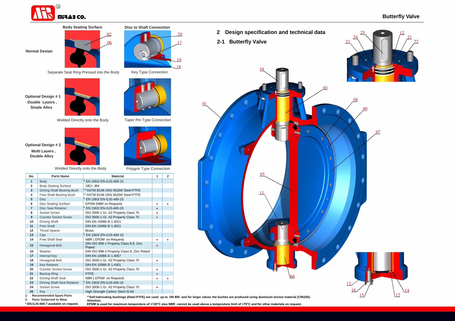
Butterfly Valve
Welded Directly onto the Body
Separate Seat Ring Pressed into the Body
Polygon Type Connection
Key Type Connection
Taper Pin Type Connection
Normal Design
Optional Design # 1
Optional Design # 2
1- Recommended Spare Parts
2- Parts Subjected to Wear
Welded Directly onto the Body
Body Seating Surface Disc to Shaft Connection
Multi Layers ,
Single Alloy
Double Layers ,
Double Alloy
* EN-GJS-500-7 available on request.
**Self-lubricating bushings (Steel-PTFE) are used up to DN 800 and for larger valves the bushes are produced using aluminum bronze material (C95200). Attention: EPDM is used for maximum temperature of +120°C also NBR cannot be used above a temperature limit of +70°C and for other materials on request .
2 Design specification and technical data
2-1 Butterfly Valve
No. Parts Name Material 1 2
1 Body ٭ EN 1563/ EN-GJS-400-15
2 Body Seating Surface 18Cr- 8Ni
3 Driving Shaft Bearing Bush ٭٭ASTM B148 UNS 95200/ Steel-PTFE
4 Free Shaft Bearing Bush ٭٭ASTM B148 UNS 95200/ Steel-PTFE
5 Disc ٭ EN 1563/ EN-GJS-400-15
6 Disc Seating Surface EPDM (NBR on Request)
7 Disc Seat Retainer ٭ EN 1563/ EN-GJS-400-15
8 Socket Screw ISO 3506-1 Gr. A2 Property Class 70
9 Counter Socket Screw ISO 3506-1 Gr. A2 Property Class 70
10 Driving Shaft DIN EN 10088-3/ 1.4021
11 Free Shaft DIN EN 10088-3/ 1.4021
12 Thrust Spacer Brass
13 Cap ٭ EN 1563/ EN-GJS-400-15
14 Free Shaft Seal NBR ( EPDM on Request)
15 Hexagonal Bolt DIN ISO 898-1 Property Class 8.8, Zinc Plated
16 Washer DIN ISO 898-2 Property Class 8, Zinc Plated
17 Internal Key DIN EN 10088-3/ 1.4057
18 Hexagonal Bolt ISO 3506-1 Gr. A2 Property Class 70
19 Key Retainer DIN EN 10088-3/ 1.4301
20 Counter Socket Screw ISO 3506-1 Gr. A2 Property Class 70
21 Backup Ring PTFE
22 Driving Shaft Seal NBR ( EPDM on Request)
23 Driving Shaft Seal Retainer ٭ EN 1563/ EN-GJS-400-15
24 Socket Screw ISO 3506-1 Gr. A2 Property Class 70
25 Key High Strength Carbon Steel-St 60

R
Butterfly Valve
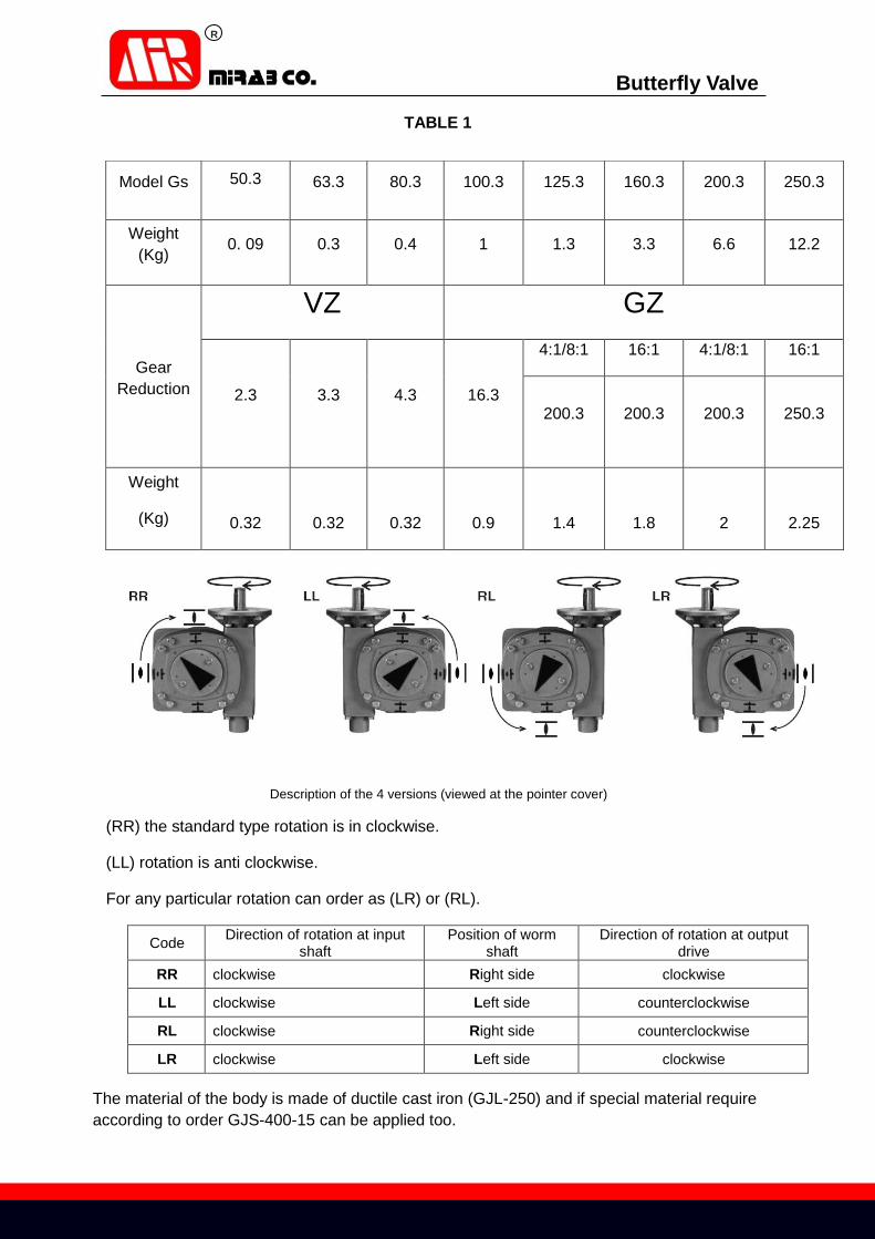
2-2 AUMA Gearbox:
Opening and closing the Butterfly valves particularly in large sizes with high pressure may be
difficult but installing gear reduction including AUMA gearbox will minimize this problem.
AUMA gearboxes change turning motion of the worm shaft to a titling 90º motion rotation of
valve’s shaft.
The rotation of cram wheel and pinion will create a smooth and reliable rotation for valve’s
disc the same as internal points of AUMA gearbox.
The beginning and end of internal gearbox shaft are equipped with two lucks nut for torque
and act as a brake. The rotation of disc in any degrees is shown by an indicator fixed on the
cover of gearbox.
Worm gearboxes on butterfly valve
Mirab co. Company has employed the AUMA gearbox for better action of valve and Obtain
high accuracy in operation.
The applied gearboxes are operation type that which are suitable for valves such as butterfly
valves.
These kinds of gearboxes with special design are not only suitable for working with electric
and pneumatic actuators they also are capable for working with hand wheel.
The AUMA gearboxes (see table 1) can be classified according to the rotation of hand wheel
or actuators:
R
Butterfly Valve
TABLE 1
Description of the 4 versions (viewed at the pointer cover)
(RR) the standard type rotation is in clockwise.
(LL) rotation is anti clockwise.
For any particular rotation can order as (LR) or (RL).
Code Direction of rotation at input
shaft Position of worm
shaft Direction of rotation at output
drive
RR clockwise Right side clockwise
LL clockwise Left side counterclockwise
RL clockwise Right side counterclockwise
LR clockwise Left side clockwise
The material of the body is made of ductile cast iron (GJL-250) and if special material require
according to order GJS-400-15 can be applied too.
250.3 200.3 160.3 125.3 100.3 80.3 63.350.3Model Gs
12.2 6.6 3.31.3 1 0.4 0.3 0. 09 Weight
(Kg)
GZVZ
Gear
Reduction
16:1 4:1/8:1 16:1 4:1/8:1
16.34.3 3.3 2.3 250.3200.3200.3200.3
2.25 2 1.8 1.4 0.9 0.32 0.32 0.32
Weight
(Kg)
R
Butterfly Valve
These gearboxes are self lucking and can counteract the high vibration.
The IP for AUMA gearboxes is 68 (IP68).
The working temperature as standard is between -25ºc up to +80ºc.
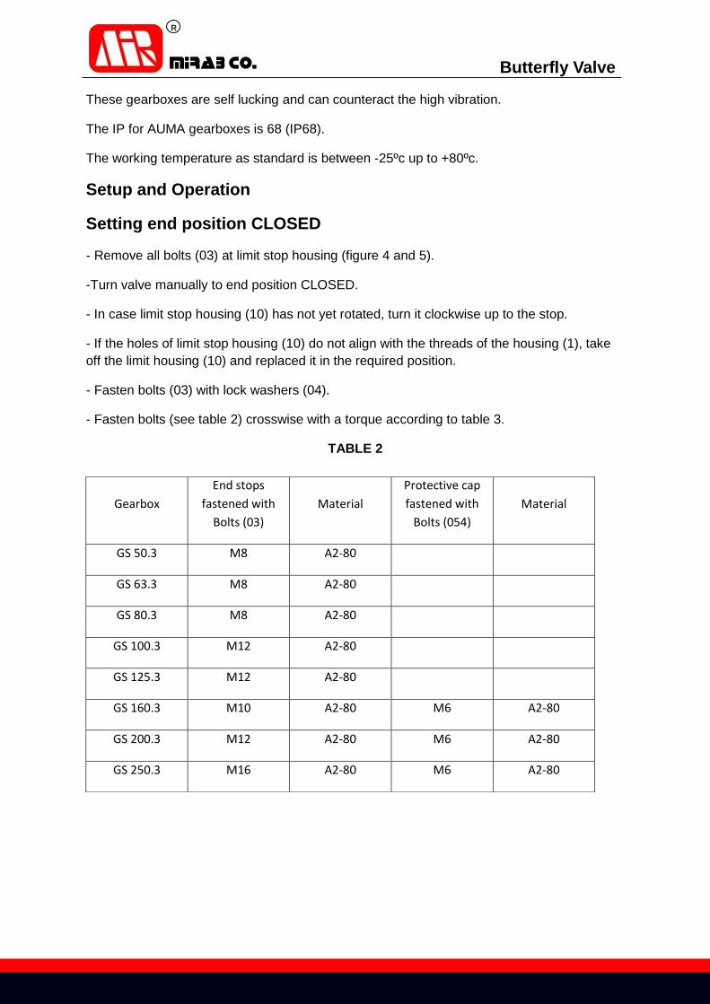
Setup and Operation
Setting end position CLOSED
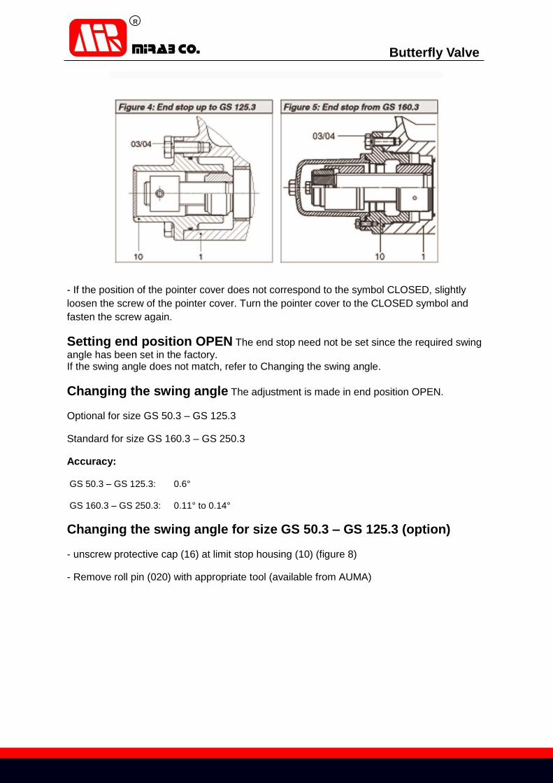
- Remove all bolts (03) at limit stop housing (figure 4 and 5).
-Turn valve manually to end position CLOSED.
- In case limit stop housing (10) has not yet rotated, turn it clockwise up to the stop.
- If the holes of limit stop housing (10) do not align with the threads of the housing (1), take
off the limit housing (10) and replaced it in the required position.
- Fasten bolts (03) with lock washers (04).
- Fasten bolts (see table 2) crosswise with a torque according to table 3.
TABLE 2
Material
Protective cap
fastened with
Bolts (054)
Material
End stops
fastened with
Bolts (03)
Gearbox
A2-80 M8 GS 50.3
A2-80 M8 GS 63.3
A2-80 M8 GS 80.3
A2-80 M12 GS 100.3
A2-80 M12 GS 125.3
A2-80 M6 A2-80 M10 GS 160.3
A2-80 M6 A2-80 M12 GS 200.3
A2-80 M6 A2-80 M16 GS 250.3

R
Butterfly Valve
Table 3
Fastening torques for bolts with different strength classes
Strength class
A2-80/A4-80
Strength class
A2-70/A4-70
Strength class
8.8 Bolts Dimensions Gearbox
Fastening torque TA [Nm] Qty. x threads Z max Y max X max Flange type
10 8 11 4 x M 6 65 5 6 GS 50.3-F05
24 18 25 4 x M 8 61 5 14 GS 50.3-F07
48 36 51 4 x M 10 61 5 14 GS 50.3-F10
48 36 51 4 x M 10 73 18 7 GS 63.3-F10
82 61 87 4 x M 12 76 13 10 GS 63.3-F12
82 61 87 4 x M 12 78 18 13 GS 80.3-F12
200 150 214 4 x M 16 88 5 23 GS 80.3-F14
200 150 214 4 x M 16 123 13 22 GS 100.3-F14
392 294 431 4 x M 20 123 8 22 GS 100.3-F16
392 294 431 4 x M 20 126 35 17 GS 125.3-F16
200 150 214 8 x M 16 126 27 17 GS 125.3-F25
200 150 214 8 x M 16 130 11 15 GS 160.3-F25
392 294 431 8 x M 20 140 0 30 GS 160.3-F30
392 294 431 8 x M 20 160 19 19 GS 200.3-F30
- 564 (1489) 8 x M 30 190 0 44 GS 200.3-F35
- 564 (1489) 8 x M 30 220 8 8 GS 250.3-F35
- - (2594) 8 x M 36 230 0 13 GS 250.3-F40
R
Butterfly Valve
- If the position of the pointer cover does not correspond to the symbol CLOSED, slightly
loosen the screw of the pointer cover. Turn the pointer cover to the CLOSED symbol and
fasten the screw again.
Setting end position OPEN The end stop need not be set since the required swing
angle has been set in the factory. If the swing angle does not match, refer to Changing the swing angle.
Changing the swing angle The adjustment is made in end position OPEN.
Optional for size GS 50.3 – GS 125.3
Standard for size GS 160.3 – GS 250.3
Accuracy:
GS 50.3 – GS 125.3: 0.6°
GS 160.3 – GS 250.3: 0.11° to 0.14°
Changing the swing angle for size GS 50.3 – GS 125.3 (option)
- unscrew protective cap (16) at limit stop housing (10) (figure 8)
- Remove roll pin (020) with appropriate tool (available from AUMA)

R
Butterfly Valve
Increasing the swing angle
- Turn end stop nut (15) back counterclockwise.
When turning back the end stop nut (015), make sure the roll
Pin (020) can still be tapped in within the oblong hole.
- Move valve into the desired end position.
- Turn end stop nut (15) clockwise until it is tight up to the stop nut (7).
Reducing the swing angle
- Move valve into the desired end position.
- Turn end stop nut (15) clockwise until it is tight up to the stop nut (7).
The end stop nut (15) must entirely cover the roll pin (020).
- Tap in roll pin (020) with tool. If slot in end stop nut (15) does not align with the hole in the
worm shaft, turn end stop nut (15) slightly counterclockwise Until it is in alignment, then tap
in roll pin.
- Check O-ring (08) and replace, if damaged.
- Replace protective cap (16).
- If gearbox is mounted to a multi-turn actuator, set limit switching again for the end position
OPEN.
Changing the swing angle for sizes GS 160.3 – Gs 250.3
- Remove all bolts (054) and pull off protective cap (16) (figure 9).

R
Butterfly Valve
- Remove screw (082) with washer (058) and setting ring (34).
Increasing the swing angle
- Turn end stop nut (15) back counterclockwise.
- Move valve into the desired end position
- Turn end stop nut (15) clockwise until it is tight up to the stop nut (7).
Reducing the swing angle
- Move valve into the desired end position.
- turn end stop nut (15) clockwise until it is tight up to the stop nut (7).
- Place setting ring (34), secure with washer (058) and screw (082).
- Check O-ring (056) and replaced, if damaged.
- Place protective cap (16), fasten bolts (054) with lock washers (055).
- Fasten bolts (see table 2) crosswise with a torque according to table 3.
- If gearbox is mounted to a multi-turn actuator, set limit switching again for the end position
OPEN.
3- Selection of Pressure Containing and Controlling Parts Material
Material for body, disc and other pressure controlling parts are carefully chosen to afford good
material properties, mechanical strength and toughness, structural stability and welding safety.
The following types of material have been selected to provide for various operating pressure and
temperatures prevailing in modern industry.
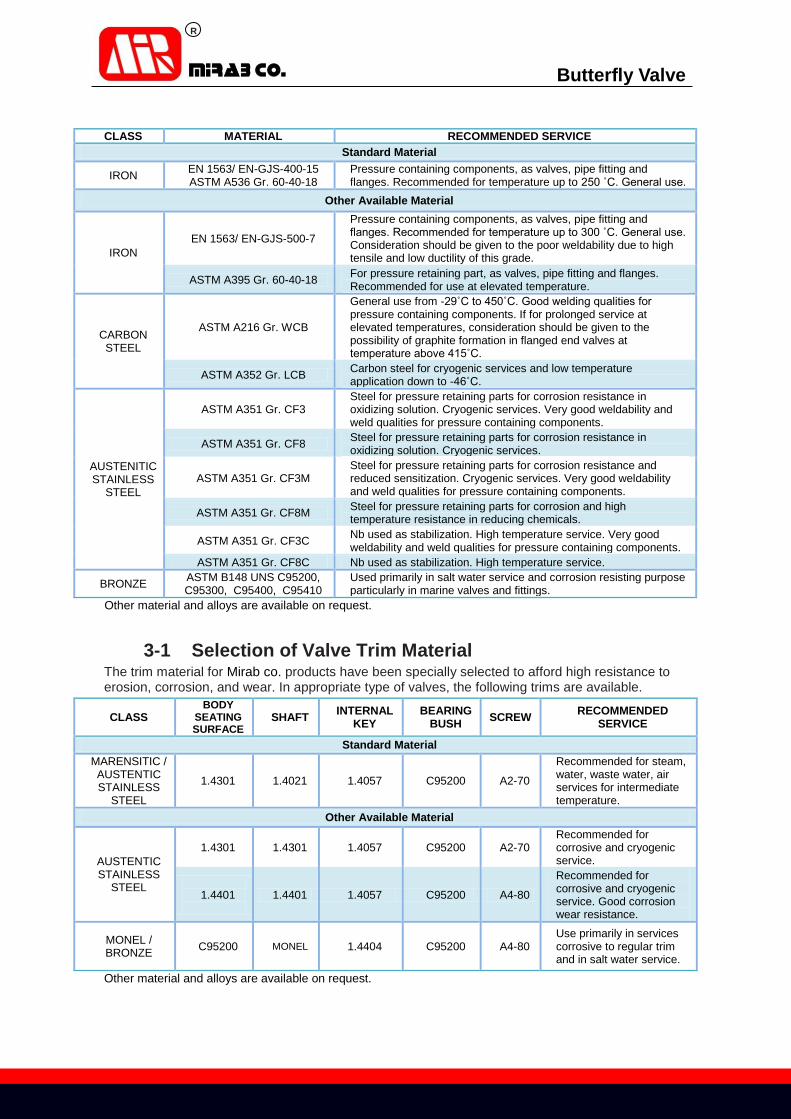
R
Butterfly Valve
RECOMMENDED SERVICE MATERIAL CLASS
Standard Material
Pressure containing components, as valves, pipe fitting and flanges. Recommended for temperature up to 250 ˚C. General use.
EN 1563/ EN-GJS-400-15 ASTM A536 Gr. 60-40-18
IRON
Other Available Material
Pressure containing components, as valves, pipe fitting and flanges. Recommended for temperature up to 300 ˚C. General use. Consideration should be given to the poor weldability due to high tensile and low ductility of this grade.
EN 1563/ EN-GJS-500-7
IRON
For pressure retaining part, as valves, pipe fitting and flanges. Recommended for use at elevated temperature.
ASTM A395 Gr. 60-40-18
General use from -29˚C to 450˚C. Good welding qualities for pressure containing components. If for prolonged service at elevated temperatures, consideration should be given to the possibility of graphite formation in flanged end valves at temperature above 415˚C.
ASTM A216 Gr. WCB CARBON STEEL
Carbon steel for cryogenic services and low temperature application down to -46˚C.
ASTM A352 Gr. LCB
Steel for pressure retaining parts for corrosion resistance in oxidizing solution. Cryogenic services. Very good weldability and weld qualities for pressure containing components.
ASTM A351 Gr. CF3
AUSTENITIC STAINLESS
STEEL
Steel for pressure retaining parts for corrosion resistance in oxidizing solution. Cryogenic services.
ASTM A351 Gr. CF8
Steel for pressure retaining parts for corrosion resistance and reduced sensitization. Cryogenic services. Very good weldability and weld qualities for pressure containing components.
ASTM A351 Gr. CF3M
Steel for pressure retaining parts for corrosion and high temperature resistance in reducing chemicals.
ASTM A351 Gr. CF8M
Nb used as stabilization. High temperature service. Very good weldability and weld qualities for pressure containing components.
ASTM A351 Gr. CF3C
Nb used as stabilization. High temperature service. ASTM A351 Gr. CF8C
Used primarily in salt water service and corrosion resisting purpose particularly in marine valves and fittings.
ASTM B148 UNS C95200, C95300, C95400, C95410
BRONZE
Other material and alloys are available on request.
3-1 Selection of Valve Trim Material
The trim material for Mirab co. products have been specially selected to afford high resistance to erosion, corrosion, and wear. In appropriate type of valves, the following trims are available.
RECOMMENDED SERVICE
SCREW BEARING
BUSH INTERNAL
KEY SHAFT
BODY SEATING SURFACE
CLASS
Standard Material
Recommended for steam, water, waste water, air services for intermediate temperature.
A2-70 C95200 1.4057 1.4021 1.4301
MARENSITIC / AUSTENTIC STAINLESS
STEEL
Other Available Material
Recommended for corrosive and cryogenic service.
A2-70 C95200 1.4057 1.4301 1.4301
AUSTENTIC STAINLESS
STEEL Recommended for corrosive and cryogenic service. Good corrosion wear resistance.
A4-80 C95200 1.4057 1.4401
1.4401
Use primarily in services corrosive to regular trim and in salt water service.
A4-80 C95200 1.4404 MONEL C95200 MONEL / BRONZE
Other material and alloys are available on request.

R
Butterfly Valve
p
2g
2V
3-2 Selection of valve nominal size (DN) and pressure (PN) Diagram 1 need to be used to take into account the flow coefficient (Kv) for the valve sizing (DN),
while diagram 2 is required for the nominal valve pressure (PN).
valve opening
(degree) Diagram 1· Sizing the valve (DN) according to the flow coefficient (Kv)
Q = Rate of flow(m3/ h)
Kv = flow coefficient (m3/h)
∆P = Head loss (bar) Q = Kv
∆H = Head loss (m) V = Average pipe velocity (m/s) ∆H =
g. = Gravitational constant (9.81 m/s2)
= Head Loss Coefficient
Kv value is the rate of water flow in cubic meters per hour in temperature from 5 to 30°C and
pressure drop of 1 bar when the valve is in completely open position.
Head Loss Coefficient ( ) of the valve at full open (90°)
DN 100 150 200 250 300 350 400 500 600 700 800 900 1000 1200 1400 1600
PN 10 - - 0.73 0.4 0.4 0.3 0.26 0.23 0.21 0.17 0.17 0.15 0.14 0.14 0.13 0.13
PN 16 0.9 0.75 0.7 0.45 0.45 0.35 0.35 0.3 0.26 0.24 0.22 0.21 0.2 0.15 0.14 0.14

R
Butterfly Valve
Nom
ina
l P
ressu
re (
ba
r)
Allowable Linear Speed (m/s)
Diagram 2 · Valve nominal pressure (PN) according to flow velocity
Important Note: For selection of valve nominal pressure, please compare linear speed of flow versus working
pressure of valve , if working point is below of red curve (red curves show nominal pressure of
valve) valve nominal pressure is suitable otherwise valve nominal pressure should be increased.
R
Butterfly Valve
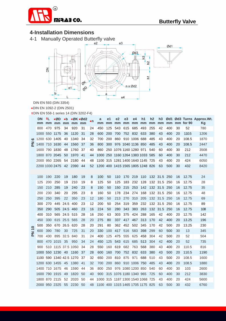
4-Installation Dimensions 4-1 Manually Operated Butterfly valve
DIN EN 593 (DIN 3354)
DIN EN 1092-2 (DIN 2501)
DIN EN 558-1 series 14 (DIN 3202-F4)
PN
6
DN mm
L mm
ØD mm
b mm
ØK mm
Ød2 mm n
a mm
e1 mm
e2 mm
e3 mm
e4 mm
h1 mm
h2 mm
h3 mm
Ød1 mm
Ød3 mm
Turns for 90
Approx.Wt. Kg
800 470 975 34 920 31 24 450 125 543 615 685 493 255 42 400 30 52 780 1000 550 1175 36 1120 31 28 600 200 700 752 832 633 380 43 400 20 110.5 1206 1200 630 1405 40 1340 34 32 700 200 860 910 1006 688 485 43 400 20 108.5 1870 1400 710 1630 44 1560 37 36 800 300 976 1040 1136 850 485 43 400 20 108.5 2447 1600 790 1830 48 1760 37 40 860 250 1076 1160 1280 971 540 60 400 30 212 3508 1800 870 2045 50 1970 41 44 1000 250 1160 1264 1383 1033 585 60 400 30 212 4470 2000 950 2265 54 2180 44 48 1100 315 1281 1400 1640 1145 725 43 400 20 424 6050 2200 1030 2475 42 2390 44 52 1200 400 1415 1565 1805 1248 826 63 500 30 432 8420
PN
10
100 190 220 19 180 19 8 100 50 110 170 219 110 132 31.5 250 16 12.75 24 125 200 250 19 210 19 8 125 50 125 183 232 128 132 31.5 250 16 12.75 28 150 210 285 19 240 23 8 150 50 150 215 253 142 132 31.5 250 16 12.75 35 200 230 340 20 295 23 8 160 50 178 234 274 168 132 31.5 250 16 12.75 48 250 250 395 22 350 23 12 180 50 213 270 310 205 132 31.5 250 16 12.75 69 300 270 445 24.5 400 23 12 200 50 254 319 359 232 132 31.5 250 16 12.75 89 350 290 505 24.5 460 23 16 224 50 280 343 383 263 132 31.5 250 16 12.75 108 400 310 565 24.5 515 28 16 250 63 303 375 424 288 165 42 400 20 12.75 142 450 330 615 25.5 565 28 20 275 80 337 417 467 313 170 42 400 20 13.25 196 500 350 670 26.5 620 28 20 291 80 362 452 502 345 170 42 500 20 13.25 230 600 390 780 30 725 31 20 330 100 417 516 583 398 299 60 500 30 13 345 700 430 895 32.5 840 31 24 400 125 475 555 625 458 304 42 500 20 52 504 800 470 1015 35 950 34 24 450 125 543 615 685 513 304 42 400 20 52 735 900 510 1115 37.5 1050 34 28 550 160 619 682 763 568 380 43 400 20 110.5 816
1000 550 1230 40 1160 37 28 600 160 700 752 832 633 380 43 500 20 110.5 1190 1100 590 1340 42.5 1270 37 32 650 200 810 875 971 688 510 43 500 20 108.5 1600 1200 630 1455 45 1380 41 32 700 200 860 910 1006 750 485 43 400 20 108.5 1880 1400 710 1675 46 1590 44 36 800 250 976 1080 1200 850 540 60 400 30 103 2600 1600 790 1915 49 1820 50 40 900 315 1076 1180 1340 965 725 60 400 30 212 3830 1800 870 2115 52 2020 50 44 1000 315 1187 1300 1540 1068 725 43 400 20 424 5600 2000 950 2325 55 2230 50 48 1100 400 1315 1465 1705 1175 825 63 500 30 432 6760

R
Butterfly Valve
Installation Dimensions: Manually Operated Butterfly valve
PN
16
DN mm
L mm
ØD mm
b mm
ØK mm
Ød2 mm n a
mm e1
mm e2
mm e3
mm e4
mm h1
mm h2
mm h3
mm Ød1 mm
Ød3 mm
Turns for 90
Approx.Wt. Kg
100 190 220 19 180 19 8 100 50 110 170 219 110 132 31.5 250 16 12.75 24 125 200 250 19 210 19 8 125 50 125 183 232 128 132 31.5 250 16 12.75 28 150 210 285 19 240 23 8 150 50 150 215 255 144 132 31.5 250 16 12.75 35 200 230 340 20 295 23 12 160 50 178 232 274 170 132 31.5 250 16 12.75 49 250 250 405 22 355 28 12 180 50 213 270 310 205 132 31.5 250 16 12.75 70 300 270 455 24.5 410 28 12 200 63 254 315 364 232 165 42 250 20 12.75 94 350 290 520 26.5 470 28 16 224 63 280 348 397 270 165 42 400 20 12.75 126 400 310 580 28 525 31 16 250 80 316 433 433 297 170 42 400 20 13.25 183 450 330 640 30 585 31 20 275 100 337 435 487 325 299 60 400 30 13 235 500 350 715 31.5 650 34 20 300 100 362 470 522 363 299 60 500 30 13 286 600 390 840 36 770 37 20 330 100 420 516 583 425 299 43 400 20 52 396 700 430 910 39.5 840 37 24 400 125 493 565 645 458 255 43 500 20 52 683 800 470 1025 43 950 41 24 450 160 573 635 715 518 380 43 400 20 110.5 771 900 510 1125 46.5 1050 41 28 550 200 656 705 801 568 485 43 400 20 108.5 857
1000 550 1255 50 1170 44 28 600 200 700 773 868 633 485 43 500 20 108.5 1318 1100 590 1355 53.5 1270 44 32 650 200 810 875 971 688 510 43 500 20 216 1682 1200 630 1485 57 1390 50 32 700 250 861 965 1084 750 540 60 400 20 103 2330 1400 710 1685 60 1590 50 36 800 315 975 1097 1257 850 726 63 400 30 212 3000 1600 790 1930 65 1820 57 40 900 315 1088 1180 1340 975 725 43 400 20 424 4022 1800 870 2130 70 2020 57 44 1000 400 1215 1365 1605 1075 826 63 500 30 432 5920 2000 950 2345 75 2230 62 48 1100 400 1335 1490 1725 1183 826 63 500 30 432 7050
PN
25
100 190 220
19 190 23 8 100 50 118 170 266 118 132 31.5
250 16 12.75 28 125 200 270 19 220 28 8 125 50 135 188 262 138 132 31.5 250 16 12.75 30 150 210 300 20 250 28 8 150 50 153 215 255 150 132 31.5 250 16 12.75 38 200 230 360 22 310 28 12 160 63 180 249 298 185 165 42 250 20 12.75 51 250 250 425 24.5 370 31 12 180 63 213 274 323 215 165 42 250 20 12.75 77 300 270 485 27.5 430 31 16 200 80 263 312 358 247 170 42 400 20 13.25 105 350 290 555 30 490 34 16 225 80 308 347 407 282 299 60 400 30 13 136 400 310 620 32 550 37 16 250 100 393 435 487 318 299 60 400 30 13 210 450 330 670 34.5 600 37 20 275 125 418 455 513 338 304 42 400 20 52 286 500 350 730 36.5 660 37 20 300 125 425 475 536 370 304 42 400 20 52 363 600 390 845 42 770 41 20 330 160 490 552 632 428 380 43 500 20 110.5 578 700 430 960 46.5 875 44 24 400 160 566 613 711 493 485 43 500 20 108.5 717 800 470 1085 51 990 50 24 450 200 616 680 776 550 485 43 500 20 108.5 816 900 510 1185 55.5 1090 50 28 550 250 710 812 931 597 540 60 400 30 103 1387
1000 550 1320 60 1210 57 28 600 250 760 865 984 670 540 60 400 30 103 1720 1100 590 1420 64.5 1310 57 32 650 250 810 915 1034 715 585 60 400 30 212 1766 1200 630 1530 69 1420 57 32 700 315 860 982 1142 765 726 63 400 30 212 2448 1400 710 1755 74 1640 62 36 800 315 988 1100 1261 890 726 63 400 30 212 2980 1600 790 1975 81 1860 62 40 900 400 1088 1270 1405 998 826 63 400 30 432 4065 1800 870 2195 88 2070 70 44 1000 400 1235 1385 1625 1108 826 63 500 30 432 5980 2000 950 2425 95 2300 70 48 1100 500 1390 1585 1830 1223 1090 73 500 40 832 7110
PN 40 and valve sizes larger than 2000 mm on request.

R
Butterfly Valve
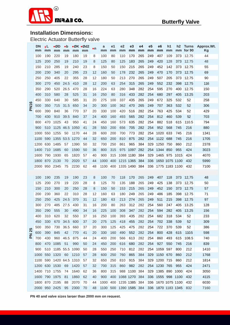
Installation Dimensions: 4-2 Electric Actuator Butterfly valve
DIN EN 593 (DIN 3354)
DIN EN 1092-2 (DIN 2501)
DIN EN 558-1 series 14 (DIN 3202-F4)
PN
6
DN mm
L mm
ØD mm
b mm
ØK mm
Ød2 mm n a mm e1
mm e2
mm e3
mm e4
mm e5
mm e6
mm h1
mm h2
mm Turns for 90
Approx.Wt. Kg
800 470 975 34 920 31 24 450 125 543 615 282 254 862 513 539 52 810
1000 550 1175 36 1120 31 28 600 160 700 752 265 249 990 633 547 110.5 1226
1200 630 1405 40 1340 34 32 700 200 860 910 282 254 1157 688 615 108.5 1893
1400 710 1630 44 1560 37 36 800 200 976 1040 282 254 1287 850 700 108.5 2470
1600 790 1830 48 1760 37 40 860 250 1076 1165 282 254 1412 971 675 212 3531
1800 870 2045 50 1970 41 44 1000 250 1260 1187 282 254 1547 1033 1000 212 4500
2000 950 2265 54 2180 44 48 1100 315 1281 1400 282 254 1647 1145 1000 424 6080
2200 1030 2475 42 2390 44 52 1200 400 1415 1570 384 329 1750 1248 1000 432 8455
PN
10
100 190 220 19 180 19 8 100 50 110 170 265 249 407 109 373 12.75 44.2 125 200 250 19 210 19 8 125 50 125 183 265 249 420 128 373 12.75 48 150 210 285 19 240 23 8 150 50 150 215 265 249 452 142 373 12.75 55 200 230 340 20 295 23 8 160 50 178 234 265 249 471 170 373 12.75 68 250 250 395 22 350 23 12 180 50 213 270 265 249 507 205 373 12.75 89 300 270 445 24.5 400 23 12 200 50 254 319 265 249 556 232 373 12.75 113 350 290 505 24.5 460 23 16 224 50 280 343 265 249 580 263 373 12.75 132 400 310 565 24.5 515 28 16 250 63 303 375 282 254 622 288 400 12.75 165 450 330 615 25.5 565 28 20 275 80 337 417 282 254 664 313 405 13.25 228 500 350 670 26.5 620 28 20 291 80 362 452 282 254 700 345 405 13.25 262 600 390 780 30 725 31 20 330 100 417 516 265 249 753 398 532 52 365 700 430 895 32.5 840 31 24 400 125 475 555 282 254 802 458 539 52 528 800 470 1015 35 950 34 24 450 125 543 615 282 254 862 513 539 52 758 900 510 1115 37.5 1050 34 28 550 160 619 682 282 254 930 568 615 110.5 839
1000 550 1230 40 1160 37 28 600 160 700 752 282 254 1000 633 615 110.5 1278 1100 590 1340 42.5 1270 37 32 650 200 810 875 282 254 1122 688 745 216 1623 1200 630 1455 45 1380 41 32 700 200 860 910 282 254 1157 750 745 216 1903 1400 710 1675 46 1590 44 36 800 250 976 1080 384 329 1365 850 860 212 2643 1600 790 1915 49 1820 50 40 900 315 1076 1180 282 254 1427 965 955 424 3878 1800 870 2115 52 2020 50 44 1000 315 1187 1300 384 329 1585 1068 1015 424 6032 2000 950 2325 55 2230 50 48 1100 400 1315 1465 384 329 1750 1175 1100 432 6800
R
Butterfly Valve
Installation Dimensions: Electric Actuator Butterfly valve
PN
16
DN mm
L mm
ØD mm
b mm
ØK mm
Ød2 mm n a
mm e1
mm e2
mm e3
mm e4
mm e5
mm e6
mm h1
mm h2
mm Turns for 90
Approx.Wt. Kg
100 190 220 19 180 19 8 100 80 110 170 265 249 407 109 373 12.75 44 125 200 250 19 210 19 8 125 80 125 183 265 249 420 128 373 12.75 48 150 210 285 19 240 23 8 150 50 150 215 265 249 452 142 373 12.75 55 200 230 340 20 295 23 12 160 50 178 232 265 249 470 170 373 12.75 69 250 250 405 22 355 28 12 180 50 213 270 265 249 507 205 373 12.75 90 300 270 450 24.5 410 28 12 200 63 254 315 265 249 552 232 398 12.75 116 350 290 520 26.5 470 28 16 224 63 280 348 282 254 595 270 400 12.75 150 400 310 580 28 525 31 16 250 80 316 433 282 254 680 297 405 13.25 203 450 330 640 30 585 31 20 275 100 337 435 265 249 672 325 532 52 258 500 350 715 31.5 650 34 20 300 100 362 470 265 249 707 363 532 52 306 600 390 840 36 770 37 20 330 100 420 516 282 254 763 425 534 52 429 700 430 910 39.5 840 37 24 400 160 493 565 282 254 812 460 539 52 703 800 470 1025 43 950 41 24 450 160 573 635 282 254 882 518 615 110.5 794 900 510 1125 46.5 1050 41 28 550 200 656 705 282 254 952 568 745 216 880
1000 550 1255 50 1170 44 28 600 200 700 773 282 254 1020 633 745 216 1341 1100 590 1355 53.5 1270 44 32 650 200 810 875 282 254 1122 688 745 216 1705 1200 630 1485 57 1390 50 32 700 250 861 965 384 329 1250 750 860 212 2378 1400 710 1685 60 1590 50 36 800 315 975 1097 282 254 1344 850 955 424 3023 1600 790 1930 65 1820 57 40 900 315 1088 1180 384 329 1465 975 1015 424 4070 1800 870 2130 70 2020 57 44 1000 400 1215 1365 384 336 1650 1075 1100 432 5990 2000 950 2345 75 2230 62 48 1100 400 1335 1490 384 336 1775 1183 1100 432 7100
PN
25
100 190 235 19 190 23 8 100 70 118 170 265 249 407 118 373 12,75 48 125 200 270 19 220 28 8 125 70 135 188 265 249 425 138 373 12,75 50 150 210 300 20 250 28 8 150 50 153 215 265 249 452 150 373 12.75 57 200 230 360 22 310 28 12 160 63 180 249 265 249 486 185 398 12.75 71 250 250 425 24.5 370 31 12 180 63 213 274 265 249 511 215 398 12.75 97 300 270 485 27.5 430 31 16 200 80 263 312 282 254 560 247 405 13.25 128 350 290 555 30 490 34 16 225 100 308 347 282 254 594 282 405 13.25 156 400 310 620 32 550 37 16 250 100 393 435 282 254 682 318 534 52 233 450 330 670 34.5 600 37 20 275 125 418 455 282 254 702 338 539 52 309 500 350 730 36.5 660 37 20 300 125 425 475 282 254 722 370 539 52 386 600 390 845 42 770 41 20 330 160 490 552 282 254 800 428 615 110.5 598 700 430 960 46.5 875 44 24 400 200 566 613 282 254 860 493 615 108.5 740 800 470 1085 51 990 50 24 450 200 616 680 282 254 927 550 745 216 839 900 510 1185 55.5 1090 50 28 550 250 710 812 282 254 1059 597 800 212 1410
1000 550 1320 60 1210 57 28 600 250 760 865 384 329 1150 670 860 212 1768 1100 590 1420 64.5 1310 57 32 650 250 810 915 384 329 1200 715 860 212 1814 1200 630 1530 69 1420 57 32 700 315 860 982 282 254 1230 765 955 424 2471 1400 710 1755 74 1640 62 36 800 315 988 1100 384 329 1385 890 1000 424 3050 1600 790 1975 81 1860 62 40 900 400 1088 1270 384 336 1555 998 1100 432 4115 1800 870 2195 88 2070 70 44 1000 400 1235 1385 384 336 1670 1075 1100 432 6030 2000 950 2425 95 2300 70 48 1100 500 1390 1585 384 336 1870 1183 1345 832 7160
PN 40 and valve sizes larger than 2000 mm on request.
R
Butterfly Valve
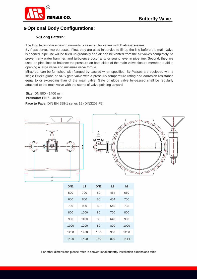
5-Optional Body Configurations:
5-1Long Pattern:
The long face-to-face design normally is selected for valves with By-Pass system.
By-Pass serves two purposes. First, they are used in service to fill-up the line before the main valve
is opened, pipe line will be filled up gradually and air can be vented from the air valves completely, to
prevent any water hammer, and turbulence occur and/ or sound level in pipe line. Second, they are
used on pipe lines to balance the pressure on both sides of the main valve closure member to aid in
opening a large valve and minimize valve torque.
Mirab co. can be furnished with flanged by-passed when specified. By-Passes are equipped with a
single OS&Y globe or NRS gate valve with a pressure/ temperature rating and corrosion resistance
equal to or exceeding than of the main valve. Gate or globe valve by-passed shall be regularly
attached to the main valve with the stems of valve pointing upward.
Size: DN 500 - 1400 mm
Pressure: PN 6 - 40 bar
Face to Face: DIN EN 558-1 series 15 (DIN3202-F5)
For other dimensions please refer to conventional butterfly installation dimensions table
DN1 L1 DN2 L2 h2
500 700 80 454 650
600 800 80 454 700
700 900 80 540 735
800 1000 80 700 800
900 1100 80 640 900
1000 1200 80 800 1000
1200 1400 100 900 1200
1400 1400 150 800 1414

R
Butterfly Valve
5-2 Short Pattern:
The short face-to-face design inherently makes the Mirab co. Butterfly Valves lighter and more
compact than a conventional valve, leading to ease of installation and lower weights and costs?
Typically, the Mirab co. short pattern Butterfly Valve is nominally less than one quarter to one thirds
(1/4 – 1/3) the weight and one quarter to one thirds (1/4 – 1/3) the face-to-face of conventional full-
bodied Butterfly Valve. The comparison table for conventional and short pattern valves shows saving
in space and weight that are achieved by specifying short pattern Butterfly Valves instead of other
types of Butterfly Valves. Should the valve body material be of stainless steel, high nickel alloy or
some other high grade material, then saving that can be made by specifying and using short pattern
valves escalate.
We can made this valve in two type :
Type 1 Sizes: DN150 - 1200
Pressures: up to PN 16
Face to Face Dimension: DIN EN 558-1 Series 13/ ISO 5752-13 (DIN3202-F16)
Flange Dimension: DIN EN 1092-2 (DIN2501)
Type 2 Sizes: NPS 6"- 48"
Pressures: Class 150 AWWA C504
Face to Face Dimension: AWWA C504 - Short Body Flange Dimension: ASME ANSI B16,5 , B16,47 Series A , AWWA C207

R
Butterfly Valve
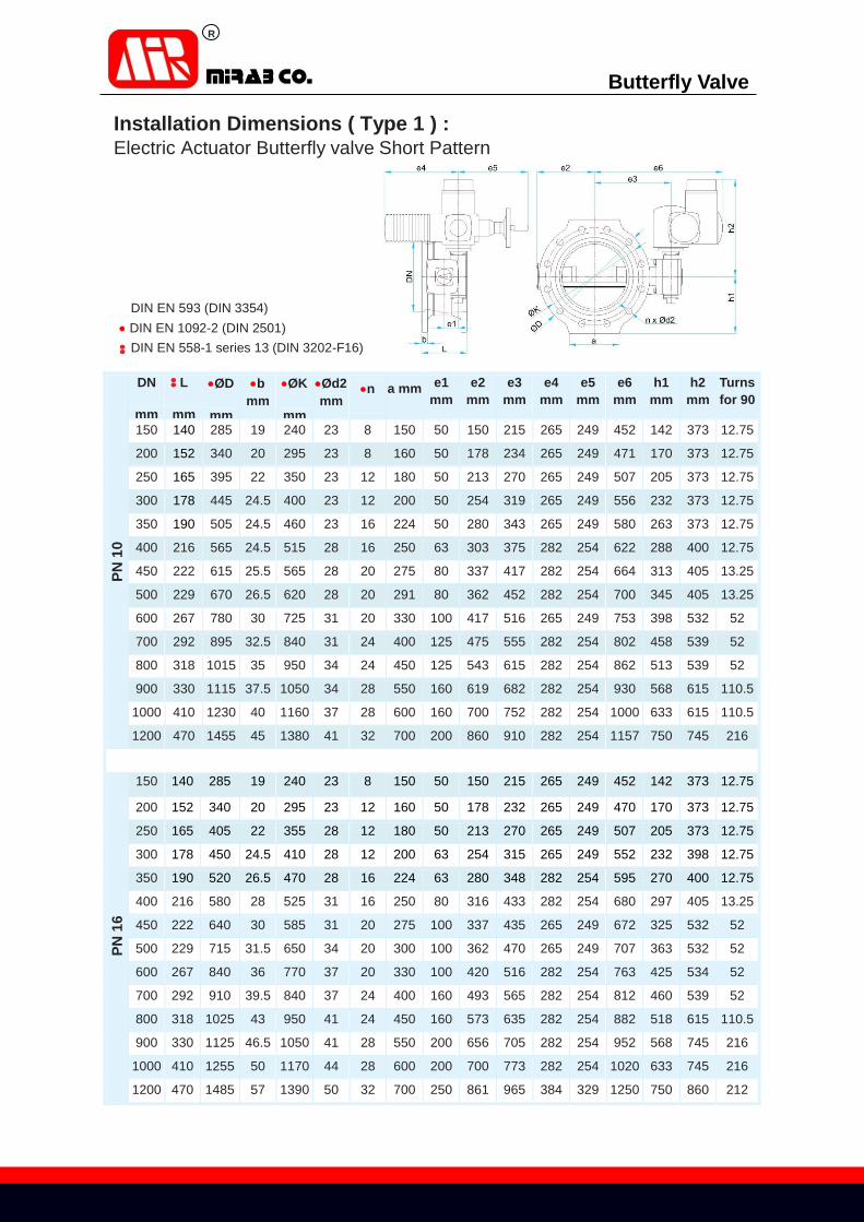
Installation Dimensions ( Type 1 ) : Manually Operated Butterfly valve Short Pattern
DIN EN 593 (DIN 3354)
DIN EN 1092-2 (DIN 2501) DIN EN 558-1 series 13 (DIN 3202-F16)
PN
10
DN
mm
L
mm
ØD
mm
b
mm ØK
mm
Ød2
mm n a
mm e1
mm e2
mm e3
mm e4
mm h1
mm h2
mm h3
mm Ød1
mm Ød3
mm Turns
for 90
150 140 285 19 240 23 8 150 50 150 215 253 142 132 31.5 250 16 12.75
200 152 340 20 295 23 8 160 50 178 234 274 168 132 31.5 250 16 12.75
250 165 395 22 350 23 12 180 50 213 270 310 205 132 31.5 250 16 12.75
300 178 445 24.5 400 23 12 200 50 254 319 359 232 132 31.5 250 16 12.75
350 190 505 24.5 460 23 16 224 50 280 343 383 263 132 31.5 250 16 12.75
400 216 565 24.5 515 28 16 250 63 303 375 424 288 165 42 400 20 12.75
450 222 615 25.5 565 28 20 275 80 337 417 467 313 170 42 400 20 13.25
500 229 670 26.5 620 28 20 291 80 362 452 502 345 170 42 500 20 13.25
600 267 780 30 725 31 20 330 100 417 516 583 398 299 60 500 30 13
700 292 895 32.5 840 31 24 400 125 475 555 625 458 304 42 500 20 52
800 318 1015 35 950 34 24 450 125 543 615 685 513 304 42 400 20 52
900 330 1115 37.5 1050 34 28 550 160 619 682 763 568 380 43 400 20 110.5
1000 410 1230 40 1160 37 28 600 160 700 752 832 633 380 43 500 20 110.5
1200 470 1455 45 1380 41 32 700 200 860 910 1006 750 485 43 400 20 108.5
PN
16
150 140 285 19 240 23 8 150 50 150 215 255 144 132 31.5 250 16 12.75
200 152 340 20 295 23 12 160 50 178 232 274 170 132 31.5 250 16 12.75
250 165 405 22 355 28 12 180 50 213 270 310 205 132 31.5 250 16 12.75
300 178 455 24.5 410 28 12 200 63 254 315 364 232 165 42 250 20 12.75
350 190 520 26.5 470 28 16 224 63 280 348 397 270 165 42 400 20 12.75
400 216 580 28 525 31 16 250 80 316 433 433 297 170 42 400 20 13.25
450 222 640 30 585 31 20 275 100 337 435 487 325 299 60 400 30 13
500 229 715 31.5 650 34 20 300 100 362 470 522 363 299 60 500 30 13
600 267 840 36 770 37 20 330 100 420 516 583 425 299 43 400 20 52
700 292 910 39.5 840 37 24 400 125 493 565 645 458 255 43 500 20 52
800 318 1025 43 950 41 24 450 160 573 635 715 518 380 43 400 20 110.5
900 330 1125 46.5 1050 41 28 550 200 656 705 801 568 485 43 400 20 108.5
1000 410 1255 50 1170 44 28 600 200 700 773 868 633 485 43 500 20 108.5
1200 470 1485 57 1390 50 32 700 250 861 965 1084 750 540 60 400 20 103
R
Butterfly Valve
Installation Dimensions ( Type 1 ) : Electric Actuator Butterfly valve Short Pattern
DIN EN 593 (DIN 3354)
DIN EN 1092-2 (DIN 2501)
DIN EN 558-1 series 13 (DIN 3202-F16)
PN
10
DN
mm
L
mm
ØD
mm
b
mm ØK
mm
Ød2
mm n a mm e1
mm e2
mm e3
mm e4
mm e5
mm e6
mm h1
mm h2
mm Turns
for 90
150 140 285 19 240 23 8 150 50 150 215 265 249 452 142 373 12.75
200 152 340 20 295 23 8 160 50 178 234 265 249 471 170 373 12.75
250 165 395 22 350 23 12 180 50 213 270 265 249 507 205 373 12.75
300 178 445 24.5 400 23 12 200 50 254 319 265 249 556 232 373 12.75
350 190 505 24.5 460 23 16 224 50 280 343 265 249 580 263 373 12.75
400 216 565 24.5 515 28 16 250 63 303 375 282 254 622 288 400 12.75
450 222 615 25.5 565 28 20 275 80 337 417 282 254 664 313 405 13.25
500 229 670 26.5 620 28 20 291 80 362 452 282 254 700 345 405 13.25
600 267 780 30 725 31 20 330 100 417 516 265 249 753 398 532 52
700 292 895 32.5 840 31 24 400 125 475 555 282 254 802 458 539 52
800 318 1015 35 950 34 24 450 125 543 615 282 254 862 513 539 52
900 330 1115 37.5 1050 34 28 550 160 619 682 282 254 930 568 615 110.5
1000 410 1230 40 1160 37 28 600 160 700 752 282 254 1000 633 615 110.5
1200 470 1455 45 1380 41 32 700 200 860 910 282 254 1157 750 745 216
PN
16
150 140 285 19 240 23 8 150 50 150 215 265 249 452 142 373 12.75
200 152 340 20 295 23 12 160 50 178 232 265 249 470 170 373 12.75
250 165 405 22 355 28 12 180 50 213 270 265 249 507 205 373 12.75
300 178 450 24.5 410 28 12 200 63 254 315 265 249 552 232 398 12.75
350 190 520 26.5 470 28 16 224 63 280 348 282 254 595 270 400 12.75
400 216 580 28 525 31 16 250 80 316 433 282 254 680 297 405 13.25
450 222 640 30 585 31 20 275 100 337 435 265 249 672 325 532 52
500 229 715 31.5 650 34 20 300 100 362 470 265 249 707 363 532 52
600 267 840 36 770 37 20 330 100 420 516 282 254 763 425 534 52
700 292 910 39.5 840 37 24 400 160 493 565 282 254 812 460 539 52
800 318 1025 43 950 41 24 450 160 573 635 282 254 882 518 615 110.5
900 330 1125 46.5 1050 41 28 550 200 656 705 282 254 952 568 745 216
1000 410 1255 50 1170 44 28 600 200 700 773 282 254 1020 633 745 216
1200 470 1485 57 1390 50 32 700 250 861 965 384 329 1250 750 860 212

R
Butterfly Valve
Installation Dimensions ( Type 2 ) : Manually Operated Butterfly valve Short Pattern
DIN EN 593 (DIN 3354)
ASME ANSI B16,5 , B16,47 Series A
AWWA C504
DN
mm
L
mm
ØD
mm
b
mm ØK
mm
Ød2
mm n a
mm e1
mm e2
mm e3
mm e4
mm h1
mm h2
mm h3
mm Ød1
mm Ød3
mm Turns
for 90
6" 127 279.4 25.4 241.3 22.4 8 150 50 150 215 255 144 132 31.5 250 16 12.75
8" 152 342.9 28.4 298.5 22.4 8 160 50 178 232 274 170 132 31.5 250 16 12.75
10" 203 406.4 30.2 362 25.4 12 180 50 213 270 310 205 132 31.5 250 16 12.75
12" 203 482.6 31.8 431.8 25.4 12 200 63 254 315 364 232 165 42 250 20 12.75
14" 203 533.4 35.1 476.3 28.5 12 224 63 280 348 397 270 165 42 400 20 12.75
16" 203 596.9 36.6 539.8 28.5 16 250 80 316 433 433 297 170 42 400 20 13.25
18" 203 635 39.6 577.9 31.8 16 275 100 337 435 487 325 299 60 400 30 13
20" 203 698.5 42.9 635 31.8 20 300 100 362 470 522 363 299 60 500 30 13
24" 203 812.8 47.8 749.3 35.1 20 330 100 420 516 583 425 299 43 400 20 52
36" 305 1168.4 90.4 1085.9 41.3 32 550 200 656 705 801 568 485 43 400 20 108.5
48" 381 1511.3 108 1422.4 41.3 44 700 250 861 965 1084 750 540 60 400 20 103

R
Butterfly Valve
Installation Dimensions ( Type 2 ) : Electric Actuator Butterfly valve Short Pattern
DIN EN 593 (DIN 3354)
ASME ANSI B16,5 , B16,47 Series A
AWWA C504
DN
mm
L
mm
ØD
mm
b
mm ØK
mm
Ød2
mm n a
mm e1
mm e2
mm e3
mm e4
mm e5
mm e6
mm h1
mm h2
mm Turns
for 90
6" 127 279.4 25.4 241.3 22.4 8 150 50 150 215 265 249 452 142 373 12.75
8" 152 342.9 28.4 298.5 22.4 8 160 50 178 232 265 249 470 170 373 12.75
10" 203 406.4 30.2 362 25.4 12 180 50 213 270 265 249 507 205 373 12.75
12" 203 482.6 31.8 431.8 25.4 12 200 63 254 315 265 249 552 232 398 12.75
14" 203 533.4 35.1 476.3 28.5 12 224 63 280 348 282 254 595 270 400 12.75
16" 203 596.9 36.6 539.8 28.5 16 250 80 316 433 282 254 680 297 405 13.25
18" 203 635 39.6 577.9 31.8 16 275 100 337 435 265 249 672 325 532 52
20" 203 698.5 42.9 635 31.8 20 300 100 362 470 265 249 707 363 532 52
24" 203 812.8 47.8 749.3 35.1 20 330 100 420 516 282 254 763 425 534 52
36" 305 1168.4 90.4 1085.9 41.3 32 550 200 656 705 282 254 952 568 745 216
48" 381 1511.3 108 1422.4 41.3 44 700 250 861 965 384 329 1250 750 860 212

R
Butterfly Valve
6-Recommended Practice for valve installation
Installation of valve: Open valve packing and remove Butterfly Valve from pallet or box carefully;
Clean and inspect Body, Disc and Flange Gasket seal surfaces for any damage or defect;
Correct small defects on the Metallic seal surfaces with fine emery paper, there must be no
raised metal above the sealing surface after the correction process;
Blend any scratches by very fine emery cloth to match damaged area with Disc elastomer
seal profile;
Examine Valve and verify all interior areas are clean and free of any dust, Sand and debris;
Examine pipeline Inside Diameter and verify it is clean and free of sand, stone, wood, welding
electrode and debris;
Flush through with water and remove all objects;
Consideration shall be given for valve maintenance and periodic over haul in pipeline layout;
Inspect to ensure pipeline flanges are installed and welded parallelly and centric, to prevent
that it does not subject the valve to externally applied loads that may affect the valve
operation;
Carefully lower Butterfly Valve between pipeline flanges and use proper gasket for valve-
pipeline sealing;
Best practice to facilitate valve installation is considering pipeline flanges distance
approximately 20 mm more than valve face-to-face;
Install proper bolts and nuts and make up the face-to-face flanges connection evenly in criss-
cross manner to appropriate torque;
Flow site procedure(s) for recommended bolt torque;
Open and close valve several times to ensure valve is operating without any problem;
Fill up and sign site service ticket with site installation supervisor;
This is worth able to mention that again pipeline shall be flushed completely and thoroughly in
order to clean and remove all debris and external objects from pipeline before pre-
commissioning.

R
Butterfly Valve
Recommended Consideration for Pipeline Layout
Prevent to install valves immediately after any junction, elbows or any disturber parts.
Reducer/ Expander
Butterfly Valve should be installed a minimum of 5 diameters downstream and 2
diameters upstream of reducer/ expander to ensure that the valve is a laminar and not
turbulent flow.
Bend
Butterfly valve should be installed a minimum of 5 diameters downstream and 2
diameters upstream of bend to avoid chocked flow preventing full operation of the valve.
Valve
Butterfly Valve may be installed on the downstream or upstream of isolating valves. If
isolating valve is throating, clearance as shown should be allowed to ensure full pressure
recovery after valve.
Note:
If full port fully open, Butterfly Valve may be installed directly on the on-off isolating valve
or outlet of check valve. Disc clearance must be considered to ensure full operation of
the valve(s).
Indicates direction of flow

R
Butterfly Valve
Conditions for installation of flanged type Butterfly valve next to Non-return valve with counter weight and
lever:
Initial start up
- After installation of the valve on the pipeline, valve should open and close easily.
- After final installation, turn on and off for several times, valve function should be the
same as before installation (in electrical actuators).
- pipeline should be clean with flushing process to avoid any damage to valve by external
particles.
For installation of butterfly valve adjacent to a non-return valve, the weight lever of the non-return valve
must be on the left hand side in flow direction and the gearbox of the butterfly valve on the right hand
side to prevent collision of the weight lever with the gearbox of the butterfly valve (see table below)..
DN
L
mm
L1
mm
a
mm
b
mm
c
mm
100 190 — — — —
150 210 — — — —
200 230 150 23 — —
250 250 150 44 — —
300 270 150 69 — 2
350 290 200 94 — 25
400 310 225 115 — 40
450 330 280 143 — 58
500 350 300 165 — 65
600 390 400 225 — 95
700 430 500 272 25 120
800 470 600 315 13 150
900 510 650 380 25 180
1000 550 750 423 34 210
1200 630 900 515 62 280
1400 710 1100 615 80 340
1600 790 1300 705 90 455
1800 870 1400 815 110 455
Tilting disc Non-return valve With counter weight
Spacer pipe Flanged type Butterfly valve
R
Butterfly Valve
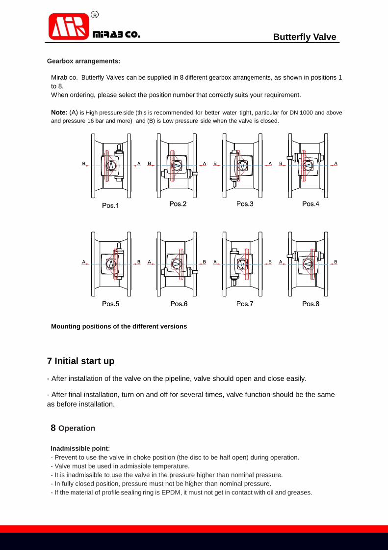
Gearbox arrangements:
Mirab co. Butterfly Valves can be supplied in 8 different gearbox arrangements, as shown in positions 1
to 8.
When ordering, please select the position number that correctly suits your requirement.
Note: (A) is High pressure side (this is recommended for better water tight, particular for DN 1000 and above
and pressure 16 bar and more) and (B) is Low pressure side when the valve is closed.
Mounting positions of the different versions
7 Initial start up
- After installation of the valve on the pipeline, valve should open and close easily.
- After final installation, turn on and off for several times, valve function should be the same
as before installation.
8 Operation
Inadmissible point:
- Prevent to use the valve in choke position (the disc to be half open) during operation.
- Valve must be used in admissible temperature.
- It is inadmissible to use the valve in the pressure higher than nominal pressure.
- In fully closed position, pressure must not be higher than nominal pressure.
- If the material of profile sealing ring is EPDM, it must not get in contact with oil and greases.
R
Butterfly Valve
Operation with hand wheel:
If any external particle caught between disc and seat, In case of using hand wheel or actuators with
high gear reduction, this action can damage the actuator, so act as follow:
During emergency hand wheel operation, if any resistance is detected, the hand wheel must be rotated
in reverse direction until the particle that caught between disc and sealing ring, go out. Then we can
move in previous direction. If it is need, you should repeat flushing operation again.
9 Maintenance
9-1 Attention:
If the valve operates continually between closed and open situation, internal parts should be
controlled according to (6-5) and be lubricated properly.
- When any maintenance is going to take place on the valve, it is necessary to close the
previous upstream valve till the pipeline is not under pressure.
- In case of using a special actuator refer to the related manual.
9-2 inspection:
- Visual inspection should be done for valve and actuator. Clean it and if any damages had
occurred those points should be touch up.
-Check sealing of flanges.
- Check easy opening and closing the valve and actuator.
- Open and close the valve with hand for several times.
- Check the valve sealing and close the valve.
1 Design specification and technical data
9-3 readjusting the sealing rubber:
Mirab co. butterfly valves are equipped with a readjust able sealing system (see section 2-1).
The profile sealing ring (06) can be readjusted in valve closed position. For this purpose,
loosen the counter socket screws and tighten evenly the tensioning screw, afterwards
tighten counter socket screw by turning in clockwise direction.
9-4 replacing the sealing rubber:
- Take away the disc from sealing rubber (see section 2-1).
- Mark the clamping ring position.
- Open the socket head screw. Do not turn the socket screw.

R
Butterfly Valve
- Take the clamping ring (07) and then apart the sealing rubber (06) from disc. -
Clean the groove of the sealing ring in the disk and clamping ring and if it is necessary, it
should paint for protection.
- Install the new sealing rubber in disc grove.
- Mount the clamping ring as marked before.
- The socket head screw (08) should be tightened until the socket screw reach and touch the
disc.
NOTE: Be careful no greases touch the sealing rubber.
9-5 Greasing internal parts of AUMA gearbox
- Lose the cover of screw and take it off.
- Lubricate the shaft and slipping surfaces.
- Place the flat washer and cover in its original place and tighten the screw.
- It is necessary to leave the flat washer on it is correct place.
Grease Specification:
TABLE 4
7
Grease Manufacturer standard
ALVINA R3 SHELL DIN51502 K-L3n
TEXANDO FO20 TEXACO DIN 51825 K-2n
R
Butterfly Valve
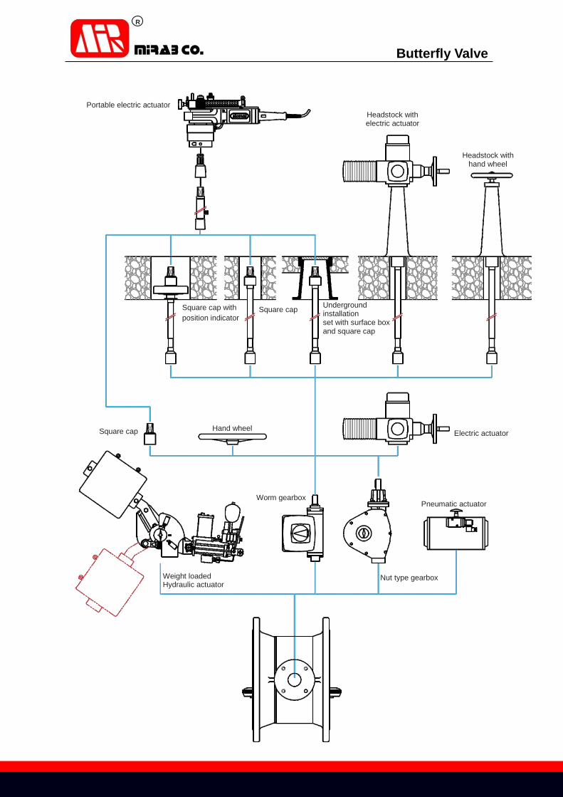
Portable electric actuator
Headstock with electric actuator
Headstock with hand wheel
Square cap with
position indicator Square cap Underground
installation set with surface box and square cap
Square cap Hand wheel Electric actuator
Worm gearbox Pneumatic actuator
Nut type gearbox Weight loaded Hydraulic actuator