busbar protection reb670 ansi customized product guide€¦ · for busbar protection applications...
TRANSCRIPT

Relion® 670 series
Busbar protection REB670 ANSICustomizedProduct Guide

Contents
1. Application.........................................................................3
2. Available functions...........................................................10
3. Differential protection.......................................................14
4. Zone selection.................................................................15
5. Current protection............................................................18
6. Voltage protection............................................................19
7. Frequency protection.......................................................19
8. Multipurpose protection...................................................20
9. Secondary system supervision.........................................20
10. Control...........................................................................20
11. Logic..............................................................................21
12. Monitoring......................................................................22
13. Metering.........................................................................23
14. Basic IED functions.........................................................24
15. Human machine interface...............................................24
16. Station communication ..................................................25
17. Remote communication..................................................26
18. Hardware description......................................................26
19. Connection diagrams......................................................29
20. Technical data................................................................33
21. Ordering.........................................................................72
Disclaimer
The information in this document is subject to change without notice and should not be construed as a commitment by ABB. ABB assumes no responsibility for any errors
that may appear in this document.
© Copyright 2012 ABB.
All rights reserved.
Trademarks
ABB and Relion are registered trademarks of the ABB Group. All other brand or product names mentioned in this document may be trademarks or registered trademarks
of their respective holders.
Busbar protection REB670 ANSI 1MRK505273-BUS DCustomized Product version: 1.2
2 ABB

1. ApplicationREB670 is designed for the selective, reliable and fastdifferential protection of busbars, T-connections and meshedcorners. REB670 can be used for protection of single anddouble busbar with or without transfer bus, double circuitbreaker or breaker-and-a-half stations. The IED is applicablefor the protection of medium voltage (MV), high voltage (HV)and extra high voltage (EHV) installations at a power systemfrequency of 50Hz or 60Hz. The IED can detect all types ofinternal phase-to-phase and phase-to-ground faults in solidlygrounded or low impedance grounded power systems, as wellas all internal multi-phase faults in isolated or high-impedancegrounded power systems.
Ordering of PT inputs inside of the busbar protection IED willallow integration of voltage related functionality like under-voltage release, residual over-voltage, power functions,metering and voltage recording during the faults. Howeverattention shall be given to the fact that inclusion of PT inputswill reduce number of available CT inputs (in total 24 analogueinputs are the product limit). Consequently when PT inputs areordered the busbar protection IED will be applicable for buseswith a fewer number of bays. Practically the number of availableCT inputs will limit the size of the station which can beprotected.
REB670 has very low requirements on the main currenttransformers (that is, CTs) and no interposing currenttransformers are necessary. For all applications, it is possible toinclude and mix main CTs with 1A and 5A rated secondarycurrent within the same protection zone. Typically, CTs with upto 10:1 ratio difference can be used within the same differentialprotection zone. Adjustment for different main CT ratios isachieved numerically by a parameter setting.
The numerical, low-impedance differential protection function isdesigned for fast and selective protection for faults withinprotected zone. All connected CT inputs are provided with arestraint feature. The minimum pick-up value for the differentialcurrent is set to give a suitable sensitivity for all internal faults.For busbar protection applications typical setting value for theminimum differential operating current is from 50% to 150% ofthe biggest CT. This setting is made directly in primaryamperes. The operating slope for the differential operatingcharacteristic is fixed to 53% in the algorithm.
The fast tripping time of the low-impedance differentialprotection function is especially advantageous for powersystem networks with high fault levels or where fast faultclearance is required for power system stability.
The advanced open CT detection algorithm detects instantlythe open CT secondary circuits and prevents differentialprotection operation without any need for additional check zone.
Differential protection zones in REB670 include a sensitiveoperational pickup. This sensitive operational pickup isdesigned to be able to detect internal busbar ground faults inlow impedance grounded power systems (that is, powersystems where the ground-fault current is limited to a certainlevel, typically between 300A and 2000A primary by a neutralpoint reactor or resistor). Alternatively this sensitive pickup canbe used when high sensitivity is required from busbardifferential protection (that is, energizing of the bus via long line).
Overall operating characteristic of the differential function inREB670 is shown in figure 1.
Busbar protection REB670 ANSI 1MRK505273-BUS DCustomized Product version: 1.2 Issued: February 2015
Revision: D
ABB 3

Differential protectionoperation characteristic
Operateregion
Diff Oper Level
I d [P
rimar
y Am
ps]
Iin [Primary Amps]
s=0.53
I d=I in
Sensitivedifferentialprotection
en06000142.vsd
Sensitive Oper Level Sens Iin Block
IEC06000142 V1 EN
Figure 1. REB670 operating characteristic
Integrated overall check zone feature, independent from anydisconnector position, is available. It can be used in doublebusbar stations to secure stability of the busbar differentialprotection in case of entirely wrong status indication of busbardisconnector in any of the feeder bays.
Flexible, software based dynamic Zone Selection enables easyand fast adaptation to the most common substationarrangements such as single busbar with or without transferbus, double busbar with or without transfer bus, breaker-and-a-half stations, double busbar-double breaker stations, ringbusbars, and so on. The software based dynamic ZoneSelections ensures:
• Dynamic linking of measured CT currents to theappropriate differential protection zone as required bysubstation topology
• Efficient merging of the two differential zones whenrequired by substation topology (that is load-transfer)
• Selective operation of busbar differential protectionensures tripping only of circuit breakers connected to thefaulty zone
• Correct marshaling of backup-trip commands frominternally integrated or external circuit breaker failureprotections to all surrounding circuit breakers
• Easy incorporation of bus-section and/or bus-coupler bays(that is, tie-breakers) with one or two sets of CTs into theprotection scheme
• Disconnector and/or circuit breaker status supervision
Advanced Zone Selection logic accompanied by optionallyavailable end-fault and/or circuit breaker failure protectionsensure minimum possible tripping time and selectivity for faultswithin the blind spot or the end zone between bay CT and baycircuit breaker. Therefore REB670 offers best possiblecoverage for such faults in feeder and bus-section/bus-couplerbays.
Optionally available circuit breaker failure protection, one forevery CT input into REB670, offers secure local back-upprotection for the circuit breakers in the station.
Optionally available four-stage, non-directional overcurrentprotections, one for every CT input into REB670, provideremote backup functionality for connected feeders and remote-end stations.
Optionally available voltage and frequency protection functionsopen possibility to include voltage release criterion for busbarprotection or to integrate independent over-, under-voltageprotection for the bus in the busbar protection IED.
Busbar protection REB670 ANSI 1MRK505273-BUS DCustomized Product version: 1.2
4 ABB

Optionally available over-current, thermal overload andcapacitor bank protection functions open possibilities tointegrate protection of shunt reactors and shunt capacitorbanks into the busbar protection IED.
It is normal practice to have just one busbar protection IED perbusbar. Nevertheless some utilities do apply two independentbusbar protection IEDs per zone of protection. REB670 IED fitsboth solutions.
A simplified bus differential protection for multi-phase faults andground faults can be obtained by using a single, one-phaseREB670 IED with external auxiliary summation currenttransformers.
The wide application flexibility makes this product an excellentchoice for both new installations and the refurbishment ofexisting installations.
Optional apparatus control for up to 30 objects can provide afacility to draw simplified single line diagram (SLD) of the stationon the local HMI. Note that in such case medium-size, graphicdisplay shall be ordered.
Application examples of REB670Examples of typical station layouts, which can be protectedwith REB670 are given below:
ANSI11000237-1-en.vsd
252
352
152
ANSI11000237 V1 EN
Figure 2. Example of T-connection
189ZA ZB
ANSI11000238-1-en.vsd
152 152 152 152 152 152152
ANSI11000238 V1 EN
Figure 3. Example of single bus station
Busbar protection REB670 ANSI 1MRK505273-BUS DCustomized Product version: 1.2
ABB 5

189 789789189 789189 789189 789189
ZA
ZB789189
xx06000013_ansi.vsd
152 152
152
152 152 152
ANSI06000013 V1 EN
Figure 4. Example of single bus station with transfer bus
189 289 189 289 189 289 189 289 189 289189 289
ZA
ZB
ANSI11000239-1-en.vsd
152152152152152152
152
ANSI11000239 V1 EN
Figure 5. Example of double bus-single breaker station
Busbar protection REB670 ANSI 1MRK505273-BUS DCustomized Product version: 1.2
6 ABB

189 289 189 289 189 289 189 289 7892089289 789189
ZAZB
xx06000015_ansi.vsd
152 152 152 152 152
789 789 789
ANSI06000015 V1 EN
Figure 6. Example of double bus-single breaker station with transfer bus
189 289 189 289 189 289 189 289 189 289 189 289 189 289 189 289189 289
ZA1
ZB1
ZA2
ZB2
xx06000016_ansi.vsd
152152152152 152 152 152 152 152
152
152
152152
ANSI06000016 V1 EN
Figure 7. Example of double bus-single breaker station with two bus-section and two bus-coupler breakers
Busbar protection REB670 ANSI 1MRK505273-BUS DCustomized Product version: 1.2
ABB 7

ZA
ZB
ANSI11000240-1-en.vsd
252 252 252 252 252
152
352
152152152152
352 352 352352
ANSI11000240 V1 EN
Figure 8. Example of breaker-and-a-half station
ZB252252 252 252 252
ZA
xx06000018_ansi.vsd
152152152152152
ANSI06000018 V1 EN
Figure 9. Example of double bus-double breaker station
Busbar protection REB670 ANSI 1MRK505273-BUS DCustomized Product version: 1.2
8 ABB

ANSI11000241-1-en.vsd
REB670
ZB87B
ZA87B27
27
3289
1289
589889
689789
3189
1189
4289
2289
2189
4189
ZA1 ZA2
ZB1 ZB2
152
252
352
452
REB670
ZB87B
ZA87B 27
27
ANSI11000241 V1 EN
Figure 10. Example of mesh or ring bus station
Note that customized REB670 is delivered without any configuration. Thus the complete IED engineering shall be done by thecustomer or its system integrator. In order to secure proper operation of the busbar protection it is strictly recommended to alwaysstart engineering work from the PCM600 project for the pre-configured REB670 which is the closest to the actual application. Then,necessary modifications shall be applied in order to adopt the customized IED configuration to suite the actual station layout. ThePCM600 project for the pre-configured REB670 IEDs is available in the Connectivity Package DVD.
Busbar protection REB670 ANSI 1MRK505273-BUS DCustomized Product version: 1.2
ABB 9

2. Available functions
Main protection functions
2 = number of basic instances0-3 = option quantities
IEC 61850 ANSI Function description Busbar
REB670
Differential protection
BUTPTRC,BCZTPDIF,BZNTPDIF,BZITGGIO
87B Busbar differential protection, 2 zones, three phase/up to 8 bays 0-1
BUSPTRC,BCZSPDIF,BZNSPDIF,BZISGGIO
87B Busbar differential protection, 2 zones, single phase/up to 24 bays 0-1
SWSGGIO Status of primary switching object for busbar protection zone selection 96
Busbar protection REB670 ANSI 1MRK505273-BUS DCustomized Product version: 1.2
10 ABB

Back-up protection functions
IEC 61850 ANSI Function description Busbar
REB670
Current protection
OC4PTOC 51_67 Four step phase overcurrent protection 0-8
PH4SPTOC 51 Four step single phase overcurrent protection 0-24
TRPTTR 49 Thermal overload protection, two time constant 0-2
CCRBRF 50BF Breaker failure protection 0-8
CCSRBRF 50BF Breaker failure protection, single phase version 0-24
GUPPDUP 37 Directional underpower protection 0-4
GOPPDOP 32 Directional overpower protection 0-4
CBPGAPC Capacitor bank protection 0-2
Voltage protection
UV2PTUV 27 Two step undervoltage protection 0-2
OV2PTOV 59 Two step overvoltage protection 0-2
ROV2PTOV 59N Two step residual overvoltage protection 0-2
VDCPTOV 60 Voltage differential protection 0-2
LOVPTUV 27 Loss of voltage check 0-2
Frequency protection
SAPTUF 81 Underfrequency protection 0-6
SAPTOF 81 Overfrequency protection 0-6
SAPFRC 81 Rate-of-change frequency protection 0-6
Multipurpose protection
CVGAPC General current and voltage protection 0-6
Busbar protection REB670 ANSI 1MRK505273-BUS DCustomized Product version: 1.2
ABB 11

Control and monitoring functions
IEC 61850 ANSI Function description Busbar
REB670
Control
SMBRREC 79 Autorecloser 0-2
APC30 3 Apparatus control for up to 6 bays, max 30 apparatuses (6CBs) incl. interlocking 0-1
QCBAY Apparatus control 1+5/APC30
LOCREM Handling of LRswitch positions 1+5/APC30
LOCREMCTRL
LHMI control of PSTO 1+5/APC30
SLGGIO Logic rotating switch for function selection and LHMI presentation 15
VSGGIO Selector mini switch 20
DPGGIO IEC61850 generic communication I/O functions 16
SPC8GGIO Single pole generic control 8 signals 5
AutomationBits AutomationBits, command function for DNP3.0 3
SingleCommand16Signals
Single command, 16 signals 4
Secondary system supervision
SDDRFUF Fuse failure supervision 0-2
Logic
Configuration logic blocks 40-420
FixedSignals Fixed signal function block 1
B16I Boolean 16 to Integer conversion 16
B16IFCVI Boolean 16 to Integer conversion with Logic Node representation 16
IB16 Integer to Boolean 16 conversion 16
IB16FCVB Integer to Boolean 16 conversion with Logic Node representation 16
Monitoring
CVMMXN Measurements 6
EVENT Event function 20
DRPRDRE Disturbance report 1
SPGGIO IEC61850 generic communication I/O functions 64
SP16GGIO IEC61850 generic communication I/O functions 16 inputs 16
MVGGIO IEC61850 generic communication I/O functions 24
BSStatReport Logical signal status report 3
RANGE_XP Measured value expander block 28
Busbar protection REB670 ANSI 1MRK505273-BUS DCustomized Product version: 1.2
12 ABB

IEC 61850 ANSI Function description Busbar
REB670
Metering
PCGGIO Pulse-counter logic 16
ETPMMTR Function for energy calculation and demand handling 6
Designed to communicate
IEC 61850 ANSI Function description Busbar
REB670
Station communication
SPA communication protocol 1
LON communication protocol 1
IEC60870-5-103 communication protocol 20/1
Operation selection between SPA and IEC60870-5-103 for SLM 1
DNP3.0 for TCP/IP and EIA-485 communication protocol 1
DNP3.0 fault records for TCP/IP and EIA-485 communication protocol 1
Parameter setting function for IEC61850 1
IntlReceive Horizontal communication via GOOSE for interlocking 59
Goose binary receive 10
Multiple command and transmit 60/10
Ethernet configuration of links 1
IEC 62439-3 Edition 1 parallel redundancy protocol 0-1
IEC 62439-3 Edition 2 parallel redundancy protocol 0-1
Busbar protection REB670 ANSI 1MRK505273-BUS DCustomized Product version: 1.2
ABB 13

Basic IED functions
IEC 61850 Function description
Basic functions included in all products
IntErrorSig Self supervision with internal event list 1
TIME Time and synchronization error 1
TimeSynch Time synchronization 1
ActiveGroup Parameter setting groups 1
Test Test mode functionality 1
ChangeLock Change lock function 1
TerminalID IED identifiers 1
Productinfo Product information 1
MiscBaseCommon Misc Base Common 1
IEDRuntimeComp IED Runtime Comp 1
RatedFreq Rated system frequency 1
SMBI Signal Matrix for binary inputs 40
SMBO Signal Matrix for binary outputs 40
SMMI Signal Matrix for mA inputs 4
SMAI Signal Matrix for analog inputs 36
Sum3Ph Summation block 3 phase 18
LocalHMI Parameter setting function for HMI in PCM600 1
LocalHMI Local HMI signals 1
AuthStatus Authority status 1
AuthorityCheck Authority check 1
AccessFTP FTP access with password 1
SPACommMap SPA communication mapping 1
DOSFRNT Denial of service, frame rate control for front port 1
DOSOEMAB Denial of service, frame rate control for OEM port AB 1
DOSOEMCD Denial of service, frame rate control for OEM port CD 1
3. Differential protectionThe function consists of differential protection algorithm,sensitive differential protection algorithm, check zone algorithm,open CT algorithm and two supervision algorithms.
Busbar differential protectionThis protection function is intended for fast and selectivetripping of faults within protected zone. For each current input,
the CT ratio can be set from the front HMI or via the parameter-setting tool, PCM600. In this way adaptation to different CTratios is provided in the simplest way. The minimum pick-upvalue for the differential current is then set to give a suitablesensitivity for all internal faults. This setting is made directly inprimary amperes. For busbar protection applications typicalsetting value for the minimum differential operating current isfrom 50% to 150% of the biggest CT. The settings can be
Busbar protection REB670 ANSI 1MRK505273-BUS DCustomized Product version: 1.2
14 ABB

changed from the front HMI or via the parameter-setting tool,PCM600.
All current inputs are indirectly provided with a restraint feature.The operation is based on the well-proven RADSS percentagerestraint stabilization principle, with an extra stabilization featureto stabilize for very heavy CT saturation. Stability for externalfaults is guaranteed if a CT is not saturated for at least twomilliseconds during each power system cycle. It is also possibleto add external tripping criteria by binary signal.
The trip command from the differential protection includingsensitive differential protection and circuit breaker failurebackup-trip commands can be set either as self-resetting orlatched. In second case the manual reset is needed in order toreset the individual bay trip output contacts.
Sensitive differential pickup BZISGGIO (87B)Differential protection zones in REB670 include a sensitiveoperational pickup. This sensitive operational pickup isdesigned to be able to detect internal busbar ground faults inlow impedance grounded power systems (i.e. power systemswhere the ground-fault current is limited to a certain level,typically between 300A and 2000A primary by a neutral pointreactor or resistor). For increased security, the sensitivedifferential protection must be externally enabled by a binarysignal (e.g. from open delta VT overvoltage relay or powertransformer neutral point overcurrent relay). Finally it is as wellpossible to set a time delay before the trip signal from thesensitive differential protection is given. This sensitive pickupcan be alternatively used in special applications when highsensitivity is required from busbar differential protection (i.e.energizing of dead bus via a long line).
Operation and operating characteristic of the sensitivedifferential protection can be set independently from theoperating characteristic of the main differential protection.However, the sensitive differential pickup is blocked as soon asthe total incoming current exceeds the pre-set level or whendifferential current exceed the set minimum pickup current forthe usual differential protection. Therefore, by appropriatesettings it can be ensured that this sensitive pickup is blockedfor all external multi-phase faults, which can cause CTsaturation. Operating characteristic of sensitive differentialcharacteristics is shown in figure 1.
Check zoneFor busbar protection in double busbar stations when dynamiczone selection is needed, it is sometimes required to includethe overall differential zone (that is, check zone). Hence, thebuilt-in, overall check zone is available in the IED. Because thebuilt-in check zone current measurement is not dependent onthe disconnector status, this feature ensures stability of Busbardifferential protection even for completely wrong status
indication from the busbar disconnectors. It is to be noted thatthe overall check zone, only supervise the usual differentialprotection operation. The external trip commands, breakerfailure backup-trip commands and sensitive differentialprotection operation are not supervised by the overall checkzone.
The overall check zone has simple current operating algorithm,which ensures check zone operation for all internal faultsregardless the fault current distribution. To achieve this, theoutgoing current from the overall check zone is used asrestraint quantity. If required, the check zone operation can beactivated externally by a binary signal.
Open CT detectionThe innovative measuring algorithm provides stability for openor short-circuited main CT secondary circuits, which means thatno separate check zone is actually necessary. Pick-up currentfor open CT detection can usually be set to detect the opencircuit condition for the smallest CT. This built-in feature allowsthe protection terminal to be set very sensitive, even to a lowervalue than the maximum CT primary rating in the station. Atdetection of problems in CT secondary circuits, the differentialprotection can be instantly blocked and an alarm is given.Alternatively, the differential protection can be automaticallydesensitized in order to ensure busbar differential protectionstability during normal through-load condition. When problemsin CT secondary circuits have been found and associated errorhas been corrected a manual reset must be given to the IED.This can be done locally from the local HMI, or remotely viabinary input or communication link.
However, it is to be noted that this feature can only be partlyutilized when the summation principle is in use.
Differential protection supervisionDual monitoring of differential protection status is available. Thefirst monitoring feature operates after settable time delay whendifferential current is higher than the user settable pickup. Thisfeature can be, for example, used to design automatic resetlogic for previously described open CT detection feature. Thesecond monitoring feature operates immediately when thebusbar through-going current is bigger than the user settablelevel. Both of these monitoring features are phase segregatedand they give out binary signals, which can be either used totrigger disturbance recorder or for alarming purposes.
4. Zone selectionTypically CT secondary circuits from every bay in the station areconnected to the busbar protection. The built-in softwarefeature called “Zone Selection” gives a simple but efficientcontrol over the connected CTs to busbar protection IED in
Busbar protection REB670 ANSI 1MRK505273-BUS DCustomized Product version: 1.2
ABB 15
order to provide fully operational differential protection schemefor multi-zone applications on both small and large buses.
The function consists of dedicated disconnector/circuit breakerstatus monitoring algorithm, bay dedicated CT-connectioncontrol algorithm and zone interconnection algorithm.
Switch status monitoringFor stations with complex primary layout (that is, double busbarsingle breaker station with or without transfer bus) theinformation about busbar disconnector position in every bay iscrucial information for busbar protection. The positions of thesedisconnectors then actually determine which CT input (that is,bay) is connected to which differential protection zone. Forsome more advanced features like end-fault or blind-spotprotection the actual status of the circuit breaker in some oreven all bays can be vital information for busbar protection aswell. The switch function block is used to take the status of twoauxiliary contacts from the primary device, evaluate them andthen to deliver the device primary contact position to the rest ofthe zone selection logic.
For such applications typically two auxiliary contacts (that is,normally open and normally closed auxiliary contacts) from eachrelevant primary switching object shall be connected to the IED.Then the status for every individual primary switching object willbe determined. The dedicated function block for each primaryswitching object is available in order to determine the status ofthe object primary contacts. By a parameter setting one of thefollowing two logical schemes can be selected for each primaryobject individually by the end user:
• If not open then closed (that is, as in RADSS schemes)
• Open or closed only when clearly indicated by aux contactstatus (that is, as in INX schemes)
Table 1 gives quick overview about both schemes.
Note that the first scheme only requires fast breaking normallyclosed auxiliary contact (that is, b contact) for proper operation.The timing of normally open auxiliary contact is not criticalbecause it is only used for supervision of the primary objectstatus. The second scheme in addition requires properly timed-adjusted, early-making normally open auxiliary contact (that is,early making a contact) for proper operation.
Regardless which scheme is used the time-delayeddisconnector/circuit breaker status supervision alarm isavailable (that is, 00 or 11 auxiliary contact status). How twointegrated differential protection zones behave whendisconnector alarm appears is freely configurable by the enduser.
It is possible by a parameter setting to override the primaryobject status as either permanently open or permanentlyclosed. This feature can be useful during testing, installationand commissioning of the busbar protection scheme. At thesame time, separate alarm is given to indicate that the actualobject status is overwritten by a setting parameter.
It is to be noted that it is as well possible to use only normallyclosed auxiliary contacts for Zone Selection logic. In that casethe Switch function blocks are not used.
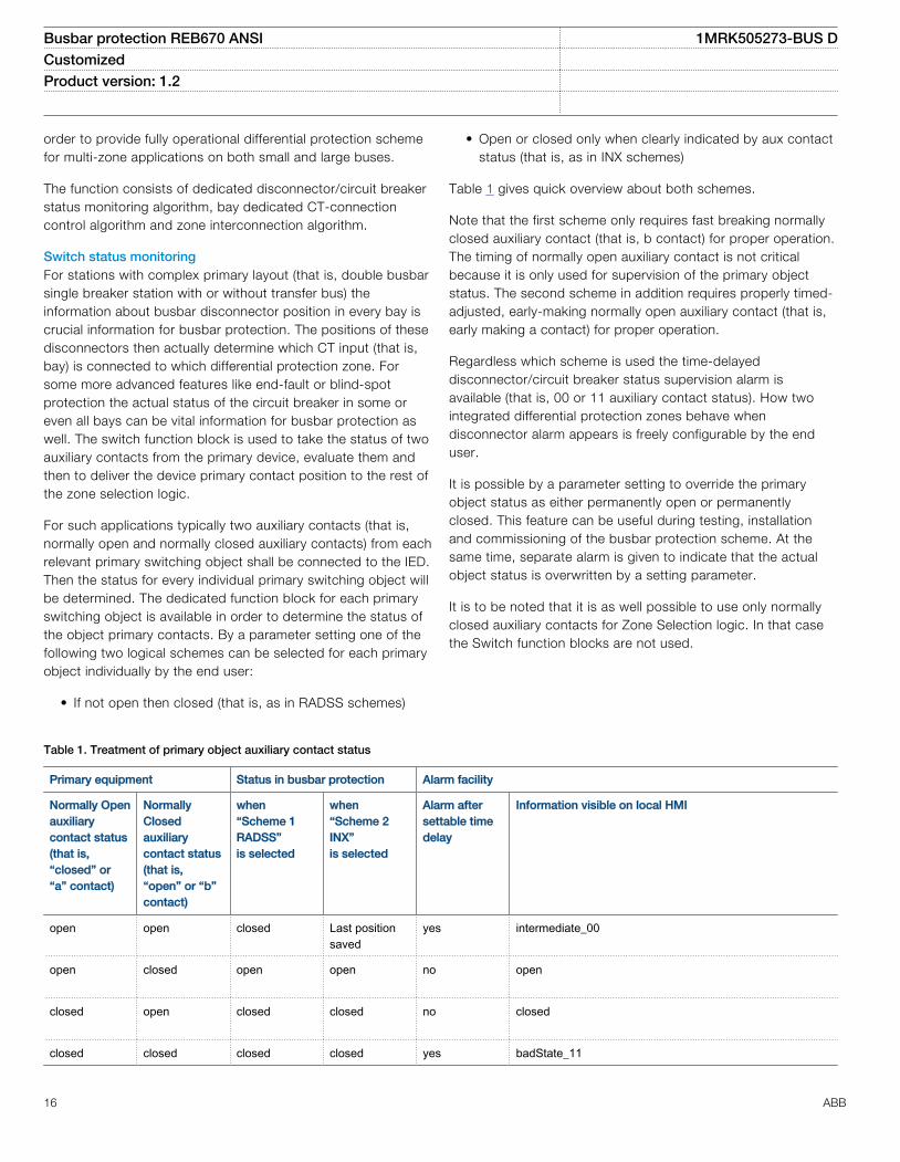
Table 1. Treatment of primary object auxiliary contact status
Primary equipment Status in busbar protection Alarm facility
Normally Openauxiliarycontact status(that is,“closed” or“a” contact)
NormallyClosedauxiliarycontact status(that is,“open” or “b”contact)
when“Scheme 1RADSS”is selected
when“Scheme 2INX”is selected
Alarm aftersettable timedelay
Information visible on local HMI
open open closed Last positionsaved
yes intermediate_00
open
closed open open no open
closed
open closed closed no closed
closed closed closed closed yes badState_11
Busbar protection REB670 ANSI 1MRK505273-BUS DCustomized Product version: 1.2
16 ABB

BayEach CT input is allocated to one dedicated bay function block.This function block is used to provide complete user interfacefor all signals from and towards this bay. It is also used toinfluence bay measured current.
It is possible by a parameter setting CTConnection to connector disconnect the CT input to the bay function block. Once theCT input is connected to the bay function block this associatedcurrent input can be included to or excluded from the twointernally available differential functions in software. This can bedone by a parameter setting for simple station layouts (that is,breaker-and-a-half stations) or alternatively via dedicated logicalscheme (that is, double busbar stations). For each bay the enduser have to select one of the following five alternatives:
• Permanently connect this bay current to zone A (that is, ZA)• Permanently connect this bay current to zone B (that is,
ZB)• Permanently connect this bay current to zone A and
inverted bay current to ZB (that is, ZA and ZB)• Connect this bay current to ZA or ZB depending on the
logical status of the two input binary signals available onthis bay function block. These two input signals will includemeasured current to the respective zone when their logicalvalue is one (that is, CntrlIncludes). This option is usedtogether with above described Switch function blocks inorder to provide complete Zone Selection logic
• Connect the bay current to ZA or ZB depending on thelogical status of the two input binary signals available onthis bay function block. These two signals will includemeasured current to the respective zone when their logicalvalue is zero (that is, CntrlExcludes). This option is typicallyused when only normally closed auxiliary contacts from thebusbar disconnector are available to the Zone Selectionlogic
At the same time, an additional feature for instantaneous ortime delayed disconnection or even inversion of the connectedbay current via separate logical signals is also available. Thisfeature is provided in order to facilitate for bus-section or bus-coupler CT disconnection for tie-breakers with a CT only on oneside of the circuit breaker. This ensures correct and fast faultclearance of faults between the CT and the circuit breakerwithin these bays. The same feature can be individually used inany feeder bay to optimize Busbar differential protectionperformance, when feeder circuit breaker is open. Thus, theend-fault protection for faults between circuit breaker and theCT is available. However, to use this feature circuit breakerauxiliary contacts and closing command to the circuit breakershall be wired to the binary inputs of the IED. Therefore, he IEDoffers best possible coverage for these special faults between
CT and circuit breaker in feeder and bus-section/bus-couplerbays.
Within the Bay function block it is decided by a parametersetting how this bay should behave during zone interconnection(that is, load transfer). For each bay individually one of thefollowing three options can be selected:
• Bay current is forced out from both zones during zoneinterconnection (used for bus-coupler bays)
• Bay current is unconditionally forced into both zonesduring zone interconnection (used in special applications)
• Bay current is connected to both zones during zoneinterconnection if the bay was previously connected to oneof the two zones (typically used for feeder bays)
The third option ensures that the feeder, which is out of service,is not connected to any of the two zones during zoneinterconnection.
Within the Bay function block it is decided by a parametersetting whether this bay should be connected to the checkzone or not. In this way the end user has simple control overthe bays, which shall be connected to the overall check zone.
By appropriate configuration logic it is possible to take any bay(that is, CT input) out of service. This can be done from thelocal HMI or externally via binary signal. In that case all internalcurrent measuring functions (that is, differential protection,sensitive differential protection, check zone, breaker failureprotection and overcurrent protection) are disabled. At thesame time, any trip command to this bay circuit breaker can beinhibited.
Via two dedicated binary input signals it is possible to:
• Trip only the bay circuit breaker (used for integrated OCprotection tripping)
• Trip the whole differential zone to which this bay ispresently connected (used for backup-trip command fromeither integrated or external bay circuit breaker failureprotection)
Finally dedicated trip binary output from the Bay function blockis available in order to provide common trip signal to the baycircuit breaker from busbar differential protection, breakerfailure protection, backup overcurrent protection and so on.
In this way the interface to the user is kept as simple aspossible and IED engineering work is quite straight forward.
Zone interconnection (Load transfer)When this feature is activated the two integrated differentialprotection zones are merged into one common, overalldifferential zone. This feature is required in double busbar
Busbar protection REB670 ANSI 1MRK505273-BUS DCustomized Product version: 1.2
ABB 17

stations when in any of the feeder bays both busbardisconnectors are closed at the same time (that is, loadtransfer). As explained in above section Bay each CT input willthen behave in the pre-set way in order to ensure propercurrent balancing during this special condition. This feature can
be started automatically (when Zone Selection logic determinesthat both busbar disconnectors in one feeder bay are closed atthe same time) or externally via dedicated binary signal. If thisfeature is active for longer time than the pre-set vale the alarmsignal is given.
5. Current protection
Four step phase overcurrent protection OC4PTOC (51/67)The four step phase overcurrent protection function OC4PTOC(51/67) has independent inverse time delay settings for step 1and 4. Step 2 and 3 are always definite time delayed.
All IEC and ANSI inverse time characteristics are availabletogether with an optional user defined time characteristic.
The directional function is voltage polarized with memory. Thefunction can be set to be directional or non-directionalindependently for each of the steps.
Second harmonic blocking level can be set for the function andcan be used to block each step individually
This function can be used as a backup bay protection (e.g. fortransformers, reactors, shunt capacitors and tie-breakers). Aspecial application is to use this phase overcurrent protection todetect short-circuits between the feeder circuit breaker andfeeder CT in a feeder bay when the circuit breaker is open. Thisfunctionality is called end-fault protection. In such caseunnecessarily operation of the busbar differential protection canbe prevented and only fast overcurrent trip signal can be sentto the remote line end. In order to utilize this functionality thecircuit breaker status and CB closing command must beconnected to the REB670. One of the overcurrent steps can beset and configured to act as end-fault protection in REB670.
Four step single phase overcurrent protection PH4SPTOC (51)Four step single phase overcurrent protection (PH4SPTOC,51)has an inverse or definite time delay independent for eachstep separately.
All IEC and ANSI time delayed characteristics are availabletogether with an optional user defined time characteristic.
The function is normally used as end fault protection to clearfaults between current transformer and circuit breaker.
Thermal overload protection, two time constant TRPTTR (49)If a power transformer or generator reaches very hightemperatures the equipment might be damaged. The insulationwithin the transformer/generator will have forced ageing. As aconsequence of this the risk of internal phase-to-phase or
phase-to-ground faults will increase. High temperature willdegrade the quality of the transformer/generator insulation.
The thermal overload protection estimates the internal heatcontent of the transformer/generator (temperature)continuously. This estimation is made by using a thermal modelof the transformer/generator with two time constants, which isbased on current measurement.
Two warning pickup levels are available. This enables actionsin the power system to be done before dangerous temperaturesare reached. If the temperature continues to increase to the tripvalue, the protection initiates a trip of the protected transformer/generator.
Breaker failure protection CCRBRF (50BF)Breaker failure protection (CCRBRF) ensures fast back-uptripping of surrounding breakers in case the own breaker fails toopen. CCRBRF (50BF) can be current based, contact based, oran adaptive combination of these two conditions.
Current check with extremely short reset time is used as checkcriterion to achieve high security against inadvertent operation.
Contact check criteria can be used where the fault currentthrough the breaker is small.
CCRBRF (50BF) can be single- or three-phase initiated to allowuse with single pole tripping applications. For the three-phaseversion of CCRBRF (50BF) the current criteria can be set tooperate only if two out of four for example, two phases or onephase plus the residual current pickups. This gives a highersecurity to the back-up trip command.
CCRBRF (50BF) function can be programmed to give a single-or three-phase re-trip of the own breaker to avoid unnecessarytripping of surrounding breakers at an incorrect initiation due tomistakes during testing.
Breaker failure protection, single phase version CCSRBRF (50BF)Breaker failure protection, single phase version (CCSRBRF,50BF) function ensures fast back-up tripping of surroundingbreakers.
A current check with extremely short reset time is used ascheck criteria to achieve a high security against unnecessaryoperation.
Busbar protection REB670 ANSI 1MRK505273-BUS DCustomized Product version: 1.2
18 ABB

CCSRBRF (50BF) can be programmed to give a re-trip of theown breaker to avoid unnecessary tripping of surroundingbreakers at an incorrect initiation due to mistakes during testing.
Directional over/underpower protection GOPPDOP/GUPPDUP(32/37)The directional over-/under-power protection GOPPDOP (32)/GUPPDUP (37) can be used wherever a high/low active,reactive or apparent power protection or alarming is required.The functions can alternatively be used to check the direction ofactive or reactive power flow in the power system. There are anumber of applications where such functionality is needed.Some of them are:
• detection of reversed active power flow• detection of high reactive power flow
Each function has two steps with definite time delay. Resettimes for both steps can be set as well.
Capacitor bank protection (CBPGAPC)Shunt Capacitor Banks (SCB) are used in a power system toprovide reactive power compensation and power factorcorrection. They are as well used as integral parts of Static VarCompensators (SVC) or Harmonic Filters installations. Capacitorbank protection (CBPGAPC) function is specially designed toprovide protection and supervision features for SCBs.
6. Voltage protection
Two step undervoltage protection UV2PTUV (27)Undervoltages can occur in the power system during faults orabnormal conditions. Two step undervoltage protection(UV2PTUV, 27) function can be used to open circuit breakers toprepare for system restoration at power outages or as long-timedelayed back-up to primary protection.
UV2PTUV (27) has two voltage steps, each with inverse ordefinite time delay.
Two step overvoltage protection OV2PTOV (59)Overvoltages may occur in the power system during abnormalconditions such as sudden power loss, tap changer regulatingfailures, open line ends on long lines etc.
Two step overvoltage protection (OV2PTOV, 59) function canbe used to detect open line ends, normally then combined witha directional reactive over-power function to supervise thesystem voltage. When triggered, the function will cause analarm, switch in reactors, or switch out capacitor banks.
OV2PTOV (59) has two voltage steps, each of them with inverseor definite time delayed.
OV2PTOV (59) has an extremely high reset ratio to allowsettings close to system service voltage.
Two step residual overvoltage protection ROV2PTOV (59N)Residual voltages may occur in the power system duringground faults.
Two step residual overvoltage protection ROV2PTOV (59N)function calculates the residual voltage from the three-phasevoltage input transformers or measures it from a single voltageinput transformer fed from a broken delta or neutral pointvoltage transformer.
ROV2PTOV (59N) has two voltage steps, each with inverse ordefinite time delay.
Reset delay ensures operation for intermittent ground faults.
Voltage differential protection VDCPTOV (60)A voltage differential monitoring function is available. Itcompares the voltages from two three phase sets of voltagetransformers and has one sensitive alarm step and one trip step.
Loss of voltage check LOVPTUV (27)Loss of voltage check (LOVPTUV, 27) is suitable for use innetworks with an automatic system restoration function.LOVPTUV (27) issues a three-pole trip command to the circuitbreaker, if all three phase voltages fall below the set value for atime longer than the set time and the circuit breaker remainsclosed.
7. Frequency protection
Underfrequency protection SAPTUF (81)Underfrequency occurs as a result of a lack of generation in thenetwork.
Underfrequency protection SAPTUF (81) is used for loadshedding systems, remedial action schemes, gas turbinestartup and so on.
SAPTUF (81) is also provided with undervoltage blocking.
The operation is based on positive sequence voltagemeasurement and requires two phase-phase or three phase-neutral voltages to be connected. For information about how toconnect analog inputs, refer to Application manual/IEDapplication/Analog inputs/Setting guidelines
Overfrequency protection SAPTOF (81)Overfrequency protection function SAPTOF (81) is applicable inall situations, where reliable detection of high fundamentalpower system frequency is needed.
Busbar protection REB670 ANSI 1MRK505273-BUS DCustomized Product version: 1.2
ABB 19

Overfrequency occurs because of sudden load drops or shuntfaults in the power network. Close to the generating plant,generator governor problems can also cause over frequency.
SAPTOF (81) is used mainly for generation shedding andremedial action schemes. It is also used as a frequency stageinitiating load restoring.
SAPTOF (81) is provided with an undervoltage blocking.
The operation is based on positive sequence voltagemeasurement and requires two phase-phase or three phase-neutral voltages to be connected. For information about how toconnect analog inputs, refer to Application manual/IEDapplication/Analog inputs/Setting guidelines
Rate-of-change frequency protection SAPFRC (81)Rate-of-change frequency protection function (SAPFRC,81)gives an early indication of a main disturbance in the system.SAPFRC (81) can be used for generation shedding, loadshedding and remedial action schemes. SAPFRC (81) candiscriminate between positive or negative change of frequency.
SAPFRC (81) is provided with an undervoltage blocking. Theoperation is based on positive sequence voltage measurementand requires two phase-phase or three phase-neutral voltagesto be connected. For information about how to connect analoginputs, refer to Application manual/IED application/Analoginputs/Setting guidelines.
8. Multipurpose protection
General current and voltage protection CVGAPCThe General current and voltage protection (CVGAPC) can beutilized as a negative or zero sequence current and/or voltageprotection detecting unsymmetrical conditions such as openphase or unsymmetrical faults.
9. Secondary system supervision
Fuse failure supervision SDDRFUFThe aim of the fuse failure supervision function (SDDRFUF) is toblock voltage measuring functions at failures in the secondarycircuits between the voltage transformer and the IED in order toavoid unwanted operations that otherwise might occur.
The fuse failure supervision function basically has three differentalgorithms, negative sequence and zero sequence basedalgorithms and an additional delta voltage and delta currentalgorithm.
The negative sequence detection algorithm is recommended forIEDs used in isolated or high-impedance grounded networks. Itis based on the negative-sequence measuring quantities, a high
value of voltage without the presence of the negative-sequencecurrent 3I2.
The zero sequence detection algorithm is recommended forIEDs used in directly or low impedance grounded networks. Itis based on the zero sequence measuring quantities, a highvalue of voltage 3V0 without the presence of the residual
current 3I0.
For better adaptation to system requirements, an operationmode setting has been introduced which makes it possible toselect the operating conditions for negative sequence and zerosequence based function. The selection of different operationmodes makes it possible to choose different interactionpossibilities between the negative sequence and zero sequencebased algorithm.
A criterion based on delta current and delta voltagemeasurements can be added to the fuse failure supervisionfunction in order to detect a three phase fuse failure, which inpractice is more associated with voltage transformer switchingduring station operations.
10. Control
Autorecloser SMBRREC (79)The autoreclosing function provides high-speed and/or delayedthree pole autoreclosing. The autoreclosing can be used fordelayed busbar restoration. One Autorecloser (SMBRREC ,79)per zone can be made available.
Apparatus control APCThe apparatus control functions are used for control andsupervision of circuit breakers, disconnectors and groundingswitches within a bay. Permission to operate is given afterevaluation of conditions from other functions such asinterlocking, synchronism check, operator place selection andexternal or internal blockings.
Apparatus control features:• Select-Execute principle to give high reliability• Selection function to prevent simultaneous operation• Selection and supervision of operator place• Command supervision• Block/deblock of operation• Block/deblock of updating of position indications• Substitution of position indications• Overriding of interlocking functions• Overriding of synchrocheck• Operation counter• Suppression of Mid position
Two types of command models can be used:
Busbar protection REB670 ANSI 1MRK505273-BUS DCustomized Product version: 1.2
20 ABB

• Direct with normal security• SBO (Select-Before-Operate) with enhanced security
In normal security, the command is processed and the resultingposition is not supervised. However with enhanced security, thecommand is processed and the resulting position is supervised.
Normal security means that only the command is evaluated andthe resulting position is not supervised. Enhanced securitymeans that the command is evaluated with an additionalsupervision of the status value of the control object. Thecommand security with enhanced security is always terminatedby a CommandTermination service primitive.
Control operation can be performed from the local HMI underauthority control if so defined.
Logic rotating switch for function selection and LHMIpresentation SLGGIOThe logic rotating switch for function selection and LHMIpresentation (SLGGIO) (or the selector switch function block) isused to get a selector switch functionality similar to the oneprovided by a hardware selector switch. Hardware selectorswitches are used extensively by utilities, in order to havedifferent functions operating on pre-set values. Hardwareswitches are however sources for maintenance issues, lowersystem reliability and an extended purchase portfolio. The logicselector switches eliminate all these problems.
Selector mini switch VSGGIOThe Selector mini switch VSGGIO function block is amultipurpose function used for a variety of applications, as ageneral purpose switch.
VSGGIO can be controlled from the menu or from a symbol onthe single line diagram (SLD) on the local HMI.
IEC 61850 generic communication I/O functions DPGGIOThe IEC 61850 generic communication I/O functions (DPGGIO)function block is used to send double indications to othersystems or equipment in the substation. It is especially used inthe interlocking and reservation station-wide logics.
Single point generic control 8 signals SPC8GGIOThe Single point generic control 8 signals (SPC8GGIO) functionblock is a collection of 8 single point commands, designed tobring in commands from REMOTE (SCADA) to those parts ofthe logic configuration that do not need extensive commandreceiving functionality (for example, SCSWI). In this way, simplecommands can be sent directly to the IED outputs, withoutconfirmation. Confirmation (status) of the result of thecommands is supposed to be achieved by other means, suchas binary inputs and SPGGIO function blocks. The commandscan be pulsed or steady.
AutomationBits, command function for DNP3.0 AUTOBITSAutomationBits function for DNP3 (AUTOBITS) is used withinPCM600 to get into the configuration of the commands comingthrough the DNP3 protocol. The AUTOBITS function plays thesame role as functions GOOSEBINRCV (for IEC 61850) andMULTICMDRCV (for LON).
Single command, 16 signalsThe IEDs can receive commands either from a substationautomation system or from the local HMI. The commandfunction block has outputs that can be used, for example, tocontrol high voltage apparatuses or for other user definedfunctionality.
11. Logic
Configurable logic blocksA number of logic blocks and timers are available for the user toadapt the configuration to the specific application needs.
• OR function block.
• INVERTER function blocks that inverts the input signal.
• PULSETIMER function block can be used, for example, forpulse extensions or limiting of operation of outputs, settablepulse time.
• GATE function block is used for whether or not a signalshould be able to pass from the input to the output.
• XOR function block.
• LOOPDELAY function block used to delay the output signalone execution cycle.
• TIMERSET function has pick-up and drop-out delayedoutputs related to the input signal. The timer has a settabletime delay.
• AND function block.
• SRMEMORY function block is a flip-flop that can set or resetan output from two inputs respectively. Each block has twooutputs where one is inverted. The memory setting controls ifthe block's output should reset or return to the state it was,after a power interruption.
• RSMEMORY function block is a flip-flop that can reset or setan output from two inputs respectively. Each block has twooutputs where one is inverted. The memory setting controls ifthe block's output should reset or return to the state it was,after a power interruption. RESET input has priority.
Busbar protection REB670 ANSI 1MRK505273-BUS DCustomized Product version: 1.2
ABB 21
Fixed signal function blockThe Fixed signals function (FXDSIGN) generates a number ofpre-set (fixed) signals that can be used in the configuration ofan IED, either for forcing the unused inputs in other functionblocks to a certain level/value, or for creating certain logic.
12. Monitoring
Measurements CVMMXN, CMMXU, VNMMXU, VMMXU,CMSQI, VMSQIThe measurement functions are used to get on-line informationfrom the IED. These service values make it possible to displayon-line information on the local HMI and on the Substationautomation system about:
• measured voltages, currents, frequency, active, reactiveand apparent power and power factor
• measured currents• primary and secondary phasors• positive, negative and zero sequence currents and voltages• mA, input currents• pulse counters
Supervision of mA input signalsThe main purpose of the function is to measure and processsignals from different measuring transducers. Many devicesused in process control represent various parameters such asfrequency, temperature and DC battery voltage as low currentvalues, usually in the range 4-20 mA or 0-20 mA.
Alarm limits can be set and used as triggers, e.g. to generatetrip or alarm signals.
The function requires that the IED is equipped with the mA inputmodule.
Event counter CNTGGIOEvent counter (CNTGGIO) has six counters which are used forstoring the number of times each counter input has beenactivated.
Disturbance report DRPRDREComplete and reliable information about disturbances in theprimary and/or in the secondary system together withcontinuous event-logging is accomplished by the disturbancereport functionality.
Disturbance report DRPRDRE, always included in the IED,acquires sampled data of all selected analog input and binarysignals connected to the function block with a, maximum of 40analog and 96 binary signals.
The Disturbance report functionality is a common name forseveral functions:
• Sequential of events• Indications• Event recorder• Trip value recorder• Disturbance recorder
The Disturbance report function is characterized by greatflexibility regarding configuration, initiating conditions, recordingtimes, and large storage capacity.
A disturbance is defined as an activation of an input to theAxRADR or BxRBDR function blocks, which are set to triggerthe disturbance recorder. All signals from start of pre-fault timeto the end of post-fault time will be included in the recording.
Every disturbance report recording is saved in the IED in thestandard Comtrade format. The same applies to all events,which are continuously saved in a ring-buffer. The local HMI isused to get information about the recordings. The disturbancereport files may be uploaded to PCM600 for further analysisusing the disturbance handling tool.
Sequential of events DRPRDREContinuous event-logging is useful for monitoring the systemfrom an overview perspective and is a complement to specificdisturbance recorder functions.
The sequential of events logs all binary input signals connectedto the Disturbance report function. The list may contain up to1000 time-tagged events stored in a ring-buffer.
Indications DRPRDRETo get fast, condensed and reliable information aboutdisturbances in the primary and/or in the secondary system it isimportant to know, for example binary signals that havechanged status during a disturbance. This information is used inthe short perspective to get information via the local HMI in astraightforward way.
There are three LEDs on the local HMI (green, yellow and red),which will display status information about the IED and theDisturbance report function (triggered).
The Indication list function shows all selected binary inputsignals connected to the Disturbance report function that havechanged status during a disturbance.
Event recorder DRPRDREQuick, complete and reliable information about disturbances inthe primary and/or in the secondary system is vital, for example,time-tagged events logged during disturbances. Thisinformation is used for different purposes in the short term (for
Busbar protection REB670 ANSI 1MRK505273-BUS DCustomized Product version: 1.2
22 ABB

example corrective actions) and in the long term (for examplefunctional analysis).
The event recorder logs all selected binary input signalsconnected to the Disturbance report function. Each recordingcan contain up to 150 time-tagged events.
The event recorder information is available for the disturbanceslocally in the IED.
The event recording information is an integrated part of thedisturbance record (Comtrade file).
Trip value recorder DRPRDREInformation about the pre-fault and fault values for currents andvoltages are vital for the disturbance evaluation.
The Trip value recorder calculates the values of all selectedanalog input signals connected to the Disturbance reportfunction. The result is magnitude and phase angle before andduring the fault for each analog input signal.
The trip value recorder information is available for thedisturbances locally in the IED.
The trip value recorder information is an integrated part of thedisturbance record (Comtrade file).
Disturbance recorder DRPRDREThe Disturbance recorder function supplies fast, complete andreliable information about disturbances in the power system. Itfacilitates understanding system behavior and related primaryand secondary equipment during and after a disturbance.Recorded information is used for different purposes in the shortperspective (for example corrective actions) and longperspective (for example functional analysis).
The Disturbance recorder acquires sampled data from selectedanalog- and binary signals connected to the Disturbance reportfunction (maximum 40 analog and 96 binary signals). The binarysignals available are the same as for the event recorder function.
The function is characterized by great flexibility and is notdependent on the operation of protection functions. It canrecord disturbances not detected by protection functions. Up toten seconds of data before the trigger instant can be saved inthe disturbance file.
The disturbance recorder information for up to 100disturbances are saved in the IED and the local HMI is used toview the list of recordings.
Event functionWhen using a Substation Automation system with LON or SPAcommunication, time-tagged events can be sent at change orcyclically from the IED to the station level. These events are
created from any available signal in the IED that is connected tothe Event function (EVENT). The event function block is used forremote communication.
Analog and double indication values are also transferredthrough EVENT function.
IEC61850 generic communication I/O functions MVGGIOIEC61850 generic communication I/O functions (MVGGIO)function is used to send the instantaneous value of an analogsignal to other systems or equipment in the substation. It canalso be used inside the same IED, to attach a RANGE aspect toan analog value and to permit measurement supervision on thatvalue.
Measured value expander block RANGE_XPThe current and voltage measurements functions (CVMMXN,CMMXU, VMMXU and VNMMXU), current and voltage sequencemeasurement functions (CMSQI and VMSQI) and IEC 61850generic communication I/O functions (MVGGIO) are providedwith measurement supervision functionality. All measuredvalues can be supervised with four settable limits: low-low limit,low limit, high limit and high-high limit. The measure valueexpander block (RANGE_XP) has been introduced to enabletranslating the integer output signal from the measuringfunctions to 5 binary signals: below low-low limit, below lowlimit, normal, above high-high limit or above high limit. Theoutput signals can be used as conditions in the configurablelogic or for alarming purpose.
13. Metering
Pulse counter logic PCGGIOPulse counter (PCGGIO) function counts externally generatedbinary pulses, for instance pulses coming from an externalenergy meter, for calculation of energy consumption values. Thepulses are captured by the binary input module and then readby the function. A scaled service value is available over thestation bus. The special Binary input module with enhancedpulse counting capabilities must be ordered to achieve thisfunctionality.
Function for energy calculation and demand handling ETPMMTROutputs from the Measurements (CVMMXN) function can beused to calculate energy consumption. Active as well asreactive values are calculated in import and export direction.Values can be read or generated as pulses. Maximum demandpower values are also calculated by the function.
Busbar protection REB670 ANSI 1MRK505273-BUS DCustomized Product version: 1.2
ABB 23

14. Basic IED functions
Time synchronizationThe time synchronization source selector is used to select acommon source of absolute time for the IED when it is a part ofa protection system. This makes it possible to compare eventand disturbance data between all IEDs in a station automationsystem.
15. Human machine interface
Human machine interfaceThe local HMI is equipped with a LCD that is used among otherthings to locally display the following crucial information:
• Connection of each bay, respecting the two differentialprotection zones and the check zone. In the ParameterSetting Tool the user sets individual bay names to facilitatethe identification of each primary bay for station personnel.
• Status of each individual primary switchgear device, forexample, open, closed, 00 as intermediate state and 11 asbad state. In PCM600 the user sets the individual primaryswitchgear object names to facilitate the identification ofeach switchgear device for the station personnel.
The local HMI is divided into zones with different functionality.
• Status indication LEDs.• Alarm indication LEDs, which consist of 15 LEDs (6 red
and 9 yellow) with user printable label. All LEDs areconfigurable from PCM600.
• Liquid crystal display (LCD).• Keypad with push buttons for control and navigation
purposes, switch for selection between local and remotecontrol and reset.
• Isolated RJ45 communication port.
IEC06000530 V1 EN
Figure 11. Example of medium graphic HMI
Busbar protection REB670 ANSI 1MRK505273-BUS DCustomized Product version: 1.2
24 ABB

IEC06000191 V1 EN
Figure 12. Bay to zone connection example
1 User settable bay name
2 Internally used bay FB
3 Connections to internal zones
IEC06000192 V1 EN
Figure 13. Example of status of primary switchgear objects
1 User settable switchgear names
2 Switchgear object status
16. Station communication
OverviewEach IED is provided with a communication interface, enablingit to connect to one or many substation level systems orequipment, either on the Substation Automation (SA) bus orSubstation Monitoring (SM) bus.
Following communication protocols are available:
• IEC 61850-8-1 communication protocol• LON communication protocol• SPA or IEC 60870-5-103 communication protocol• DNP3.0 communication protocol
Theoretically, several protocols can be combined in the sameIED.
IEC 61850-8-1 communication protocolThe IED is equipped with single or double optical Ethernet rearports (order dependent) for IEC 61850-8-1 station buscommunication. The IEC 61850-8-1 communication is also
Busbar protection REB670 ANSI 1MRK505273-BUS DCustomized Product version: 1.2
ABB 25

possible from the optical Ethernet front port. IEC 61850-8-1protocol allows intelligent electrical devices (IEDs) from differentvendors to exchange information and simplifies systemengineering. Peer-to-peer communication according to GOOSEis part of the standard. Disturbance files uploading is provided.
Serial communication, LONExisting stations with ABB station bus LON can be extendedwith use of the optical LON interface. This allows full SAfunctionality including peer-to-peer messaging and cooperationbetween existing ABB IED's and the new IED 670.
SPA communication protocolA single glass or plastic port is provided for the ABB SPAprotocol. This allows extensions of simple substationautomation systems but the main use is for SubstationMonitoring Systems SMS.
IEC 60870-5-103 communication protocolA single glass or plastic port is provided for theIEC60870-5-103 standard. This allows design of simplesubstation automation systems including equipment fromdifferent vendors. Disturbance files uploading is provided.
DNP3.0 communication protocolAn electrical RS485 and an optical Ethernet port is available forthe DNP3.0 communication. DNP3.0 Level 2 communicationwith unsolicited events, time synchronizing and disturbancereporting is provided for communication to RTUs, Gateways orHMI systems.
Multiple command and transmitWhen 670 IED's are used in Substation Automation systemswith LON, SPA or IEC60870-5-103 communication protocolsthe Event and Multiple Command function blocks are used asthe communication interface for vertical communication tostation HMI and gateway and as interface for horizontal peer-to-peer communication (over LON only).
IEC 62439-3 Parallel Redundant ProtocolRedundant station bus communication according to IEC62439-3 Edition 1 and IEC 62439-3 Edition 2 are available asoptions in 670 series IEDs. IEC 62439-3 parallel redundantprotocol is an optional quantity and the selection is made atordering. Redundant station bus communication according toIEC 62439-3 uses both port AB and port CD on the OEMmodule.
Select IEC 62439-3 Edition 1 protocol at thetime of ordering when an existing redundantstation bus DuoDriver installation is extended.Select IEC 62439-3 Edition 2 protocol at thetime of ordering for new installations withredundant station bus.
IEC 62439-3 Edition 1 is NOT compatiblewith IEC 62439-3 Edition 2.
17. Remote communication
Analog and binary signal transfer to remote endThree analog and eight binary signals can be exchangedbetween two IEDs. This functionality is mainly used for the linedifferential protection. However it can be used in other productsas well. An IED can communicate with up to 4 remote IEDs.
Binary signal transfer to remote end, 192 signalsIf the communication channel is used for transfer of binarysignals only, up to 192 binary signals can be exchangedbetween two IEDs. For example, this functionality can be usedto send information such as status of primary switchgearapparatus or intertripping signals to the remote IED. An IED cancommunicate with up to 4 remote IEDs.
For REB670 primary apparatus position indication can beexchanged between the single phase IEDs.
Line data communication module, short range LDCMThe line data communication module (LDCM) is used forcommunication between the IEDs situated at distances <68miles or from the IED to optical to electrical converter with G.703 or G.703E1 interface located on a distances <1.9 milesaway. The LDCM module sends and receives data, to and fromanother LDCM module. The IEEE/ANSI C37.94 standard formatis used.
18. Hardware description
Hardware modulesPower supply module PSMThe power supply module is used to provide the correct internalvoltages and full isolation between the terminal and the batterysystem. An internal fail alarm output is available.
Binary input module BIMThe binary input module has 16 optically isolated inputs and isavailable in two versions, one standard and one with enhancedpulse counting capabilities on the inputs to be used with thepulse counter function. The binary inputs are freelyprogrammable and can be used for the input of logical signalsto any of the functions. They can also be included in thedisturbance recording and event-recording functions. Thisenables extensive monitoring and evaluation of operation of theIED and for all associated electrical circuits.
Busbar protection REB670 ANSI 1MRK505273-BUS DCustomized Product version: 1.2
26 ABB

Binary output module BOMThe binary output module has 24 independent output relaysand is used for trip output or any signaling purpose.
Static binary output module SOMThe static binary output module has six fast static outputs andsix change over output relays for use in applications with highspeed requirements.
Binary input/output module IOMThe binary input/output module is used when only a few inputand output channels are needed. The ten standard outputchannels are used for trip output or any signaling purpose. Thetwo high speed signal output channels are used for applicationswhere short operating time is essential. Eight optically isolatedbinary inputs cater for required binary input information.
mA input module MIMThe milli-ampere input module is used to interface transducersignals in the –20 to +20 mA range from for example OLTCposition, temperature or pressure transducers. The module hassix independent, galvanically separated channels.
Optical ethernet module OEMThe optical fast-ethernet module is used to connect an IED tothe communication buses (like the station bus) that use the IEC61850-8-1 protocol (port A, B). The module has one or twooptical ports with ST connectors.
Serial and LON communication module SLM, supports SPA/IEC 60870-5-103, LON and DNP 3.0The serial and LON communication module (SLM) is used forSPA, IEC 60870-5-103, DNP3 and LON communication. Themodule has two optical communication ports for plastic/plastic,plastic/glass or glass/glass. One port is used for serialcommunication (SPA, IEC 60870-5-103 and DNP3 port ordedicated IEC 60870-5-103 port depending on ordered SLMmodule) and one port is dedicated for LON communication.
Line data communication module LDCMEach module has one optical port, one for each remote end towhich the IED communicates.
Alternative cards for Short range (850 nm multi mode) areavailable.
Galvanic RS485 serial communication moduleThe Galvanic RS485 communication module (RS485) is usedfor DNP3.0 communication. The module has one RS485communication port. The RS485 is a balanced serialcommunication that can be used either in 2-wire or 4-wireconnections. A 2-wire connection uses the same signal for RXand TX and is a multidrop communication with no dedicatedMaster or slave. This variant requires however a control of theoutput. The 4-wire connection has separated signals for RX andTX multidrop communication with a dedicated Master and therest are slaves. No special control signal is needed in this case.
GPS time synchronization module GTMThis module includes a GPS receiver used for timesynchronization. The GPS has one SMA contact for connectionto an antenna. It also includes an optical PPS ST-connectoroutput.
IRIG-B Time synchronizing moduleThe IRIG-B time synchronizing module is used for accurate timesynchronizing of the IED from a station clock.
Electrical (BNC) and optical connection (ST) for 0XX and 12XIRIG-B support.
Transformer input module TRMThe transformer input module is used to galvanically separateand transform the secondary currents and voltages generatedby the measuring transformers. The module has twelve inputs indifferent combinations of currents and voltage inputs.
Alternative connectors of Ring lug or Compression type can beordered.
Layout and dimensions
Busbar protection REB670 ANSI 1MRK505273-BUS DCustomized Product version: 1.2
ABB 27

Dimensions
xx05000059.vsd
EA
BC
F
D
IEC05000059 V1 EN
Figure 14. 1/1 x 19” case with rear cover
Case size A B C D E F
6U, 1/1 x 19” 10.47 17.65 7.92 9.53 9.96 16.94
(inches)
Mounting alternatives• 19” rack mounting kit• Flush mounting kit with cut-out dimensions:
– 1/2 case size (h) 10.01 inches (w) 8.27 inches– 1/1 case size (h) 10.01 inches (w) 17.11 inches
• Wall mounting kit
See ordering for details about available mounting alternatives.
Busbar protection REB670 ANSI 1MRK505273-BUS DCustomized Product version: 1.2
28 ABB

19. Connection diagrams
Table 2. Designations for 1/1 x 19” casing with 2 TRM slots
1MRK002801-AC-6-670-1.2-PG V1 EN
Module Rear Positions
PSM X11
BIM, BOM, SOM,IOM or MIM
X31 and X32 etc. to X131and X132
SLM X301:A, B, C, D
LDCM, IRIG-B orRS485
X302
LDCM or RS485 X303
OEM X311:A, B, C, D
LDCM, RS485 orGTM
X312, X313, X322, X323
TRM 1 X401
TRM 2 X411
1MRK002802-AB-10-670-1.2-PG-ANSI V1 EN
Figure 15. Transformer input module (TRM)
■ Indicates high polarity. See table 3
Note that internal polarity can be adjusted by setting of analog input CT neutral direction and/or on SMAI pre-processing function blocks.
Busbar protection REB670 ANSI 1MRK505273-BUS DCustomized Product version: 1.2
ABB 29
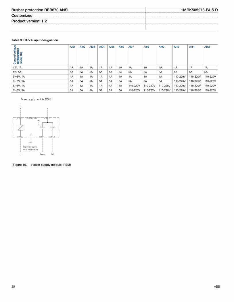
Table 3. CT/VT-input designation
Cur
rent
/vo
ltag
eco
nfig
urat
ion
(50/
60 H
z)
AI01 AI02 AI03 AI04 AI05 AI06 AI07 AI08 AI09 AI10 AI11 AI12
12I, 1A 1A 1A 1A 1A 1A 1A 1A 1A 1A 1A 1A 1A12I, 5A 5A 5A 5A 5A 5A 5A 5A 5A 5A 5A 5A 5A9I+3V, 1A 1A 1A 1A 1A 1A 1A 1A 1A 1A 110-220V 110-220V 110-220V9I+3V, 5A 5A 5A 5A 5A 5A 5A 5A 5A 5A 110-220V 110-220V 110-220V6I+6V, 1A 1A 1A 1A 1A 1A 1A 110-220V 110-220V 110-220V 110-220V 110-220V 110-220V6I+6V, 5A 5A 5A 5A 5A 5A 5A 110-220V 110-220V 110-220V 110-220V 110-220V 110-220V
1MRK002802-AB-7-670-1.2-PG-ANSI V1 EN
Figure 16. Power supply module (PSM)
Busbar protection REB670 ANSI 1MRK505273-BUS DCustomized Product version: 1.2
30 ABB
1MRK002802-AB-11-670-1.2-PG-ANSI V1 EN
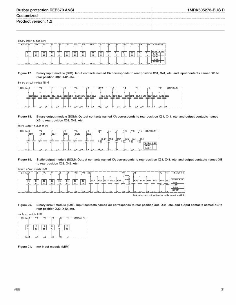
Figure 17. Binary input module (BIM). Input contacts named XA corresponds to rear position X31, X41, etc. and input contacts named XB torear position X32, X42, etc.
1MRK002802-AB-12-670-1.2-PG-ANSI V1 EN
Figure 18. Binary output module (BOM). Output contacts named XA corresponds to rear position X31, X41, etc. and output contacts namedXB to rear position X32, X42, etc.
1MRK002802-AB-13-670-1.2-PG-ANSI V1 EN
Figure 19. Static output module (SOM). Output contacts named XA corresponds to rear position X31, X41, etc. and output contacts named XBto rear position X32, X42, etc.
1MRK002802-AB-14-670-1.2-PG-ANSI V1 EN
Figure 20. Binary in/out module (IOM). Input contacts named XA corresponds to rear position X31, X41, etc. and output contacts named XB torear position X32, X42, etc.
1MRK002802-AB-15-670-1.2-PG-ANSI V1 EN
Figure 21. mA input module (MIM)
Busbar protection REB670 ANSI 1MRK505273-BUS DCustomized Product version: 1.2
ABB 31

1MRK002802-AB-8-670-1.2-PG-ANSI V1 EN
Figure 22. IED with basic functionality communication interfaces
Busbar protection REB670 ANSI 1MRK505273-BUS DCustomized Product version: 1.2
32 ABB

20. Technical data
General
Definitions
Reference value The specified value of an influencing factor to which are referred the characteristics of the equipment
Nominal range The range of values of an influencing quantity (factor) within which, under specified conditions, the equipment meets the specifiedrequirements
Operative range The range of values of a given energizing quantity for which the equipment, under specified conditions, is able to perform itsintended functions according to the specified requirements
Energizing quantities, rated values and limitsAnalog inputs
Table 4. TRM - Energizing quantities, rated values and limits for protection transformer modules
Quantity Rated value Nominal range
Current In = 1 or 5 A (0.2-40) × In
Operative range (0-100) x In
Permissive overload 4 × In cont.100 × In for 1 s *)
Burden < 150 mVA at In = 5 A< 20 mVA at In = 1 A
Ac voltage Vn = 120 V 0.5–288 V
Operative range (0–340) V
Permissive overload 420 V cont.450 V 10 s
Burden < 20 mVA at 110 V
Frequency fn = 60/50 Hz ± 5%
*) max. 350 A for 1 s when COMBITEST test switch is included.
Table 5. MIM - mA input module
Quantity: Rated value: Nominal range:
Input resistance Rin = 194 Ohm -
Input range ± 5, ± 10, ± 20mA0-5, 0-10, 0-20, 4-20mA
-
Power consumptioneach mA-boardeach mA input
£ 2 W£ 0.1 W
-
Busbar protection REB670 ANSI 1MRK505273-BUS DCustomized Product version: 1.2
ABB 33

Table 6. OEM - Optical ethernet module
Quantity Rated value
Number of channels 1 or 2
Standard IEEE 802.3u 100BASE-FX
Type of fiber 62.5/125 mm multimode fibre
Wave length 1300 nm
Optical connector Type ST
Communication speed Fast Ethernet 100 MB
Auxiliary DC voltage
Table 7. PSM - Power supply module
Quantity Rated value Nominal range
Auxiliary dc voltage, EL (input) EL = (24 - 60) VEL = (90 - 250) V
EL ± 20%EL ± 20%
Power consumption 50 W typically -
Auxiliary DC power in-rush < 5 A during 0.1 s -
Binary inputs and outputs
Table 8. BIM - Binary input module
Quantity Rated value Nominal range
Binary inputs 16 -
DC voltage, RL 24/30 V48/60 V125 V220/250 V
RL ± 20%RL ± 20%RL ± 20%RL ± 20%
Power consumption24/30 V, 50mA48/60 V, 50mA125 V, 50mA220/250 V, 50mA220/250 V, 110mA
max. 0.05 W/inputmax. 0.1 W/inputmax. 0.2 W/inputmax. 0.4 W/inputmax. 0.5 W/input
-
Counter input frequency 10 pulses/s max -
Oscillating signal discriminator Blocking settable 1–40 HzRelease settable 1–30 Hz
Debounce filter Settable 1–20ms
Maximum 176 binary input channels may beactivated simultaneously with influencingfactors within nominal range.
Busbar protection REB670 ANSI 1MRK505273-BUS DCustomized Product version: 1.2
34 ABB

Table 9. BIM - Binary input module with enhanced pulse counting capabilities
Quantity Rated value Nominal range
Binary inputs 16 -
DC voltage, RL 24/30 V48/60 V125 V220/250 V
RL ± 20%RL ± 20%RL ± 20%RL ± 20%
Power consumption24/30 V48/60 V125 V220/250 V
max. 0.05 W/inputmax. 0.1 W/inputmax. 0.2 W/inputmax. 0.4 W/input
-
Counter input frequency 10 pulses/s max -
Balanced counter input frequency 40 pulses/s max -
Oscillating signal discriminator Blocking settable 1–40 HzRelease settable 1–30 Hz
Maximum 176 binary input channels may beactivated simultaneously with influencingfactors within nominal range.
Table 10. IOM - Binary input/output module
Quantity Rated value Nominal range
Binary inputs 8 -
DC voltage, RL 24/30 V48/60 V125 V220/250 V
RL ± 20%RL ± 20%RL ± 20%RL ± 20%
Power consumption24/30 V, 50 mA48/60 V, 50 mA125 V, 50 mA220/250 V, 50 mA220/250 V, 110 mA
max. 0.05 W/inputmax. 0.1 W/inputmax. 0.2 W/inputmax. 0.4 W/inputmax. 0.5 W/input
-
Counter input frequency 10 pulses/s max
Oscillating signal discriminator Blocking settable 1-40 HzRelease settable 1-30 Hz
Debounce filter Settable 1-20 ms
Maximum 176 binary input channels may beactivated simultaneously with influencingfactors within nominal range.
Busbar protection REB670 ANSI 1MRK505273-BUS DCustomized Product version: 1.2
ABB 35

Table 11. IOM - Binary input/output module contact data (reference standard: IEC 61810-2)
Function or quantity Trip and signal relays Fast signal relays (parallelreed relay)
Binary outputs 10 2
Max system voltage 250 V AC, DC 250 V DC
Test voltage across open contact, 1 min 1000 V rms 800 V DC
Current carrying capacityPer relay, continuousPer relay, 1 sPer process connector pin, continuous
8 A10 A12 A
8 A10 A12 A
Making capacity at inductive load with L/R>10 ms 0.2 s1.0 s
30 A10 A
0.4 A0.4 A
Making capacity at resistive load 0.2 s1.0 s
30 A10 A
220–250 V/0.4 A110–125 V/0.4 A48–60 V/0.2 A24–30 V/0.1 A
Breaking capacity for AC, cos φ > 0.4 250 V/8.0 A 250 V/8.0 A
Breaking capacity for DC with L/R < 40 ms 48 V/1 A110 V/0.4 A125 V/0.35 A220 V/0.2 A250 V/0.15 A
48 V/1 A110 V/0.4 A125 V/0.35 A220 V/0.2 A250 V/0.15 A
Maximum capacitive load - 10 nF
Busbar protection REB670 ANSI 1MRK505273-BUS DCustomized Product version: 1.2
36 ABB
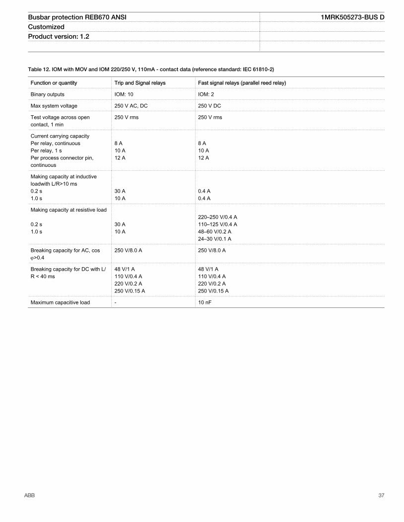
Table 12. IOM with MOV and IOM 220/250 V, 110mA - contact data (reference standard: IEC 61810-2)
Function or quantity Trip and Signal relays Fast signal relays (parallel reed relay)
Binary outputs IOM: 10 IOM: 2
Max system voltage 250 V AC, DC 250 V DC
Test voltage across opencontact, 1 min
250 V rms 250 V rms
Current carrying capacityPer relay, continuousPer relay, 1 sPer process connector pin,continuous
8 A10 A12 A
8 A10 A12 A
Making capacity at inductiveloadwith L/R>10 ms0.2 s1.0 s
30 A10 A
0.4 A0.4 A
Making capacity at resistive load 0.2 s1.0 s
30 A10 A
220–250 V/0.4 A110–125 V/0.4 A48–60 V/0.2 A24–30 V/0.1 A
Breaking capacity for AC, cosj>0.4
250 V/8.0 A 250 V/8.0 A
Breaking capacity for DC with L/R < 40 ms
48 V/1 A110 V/0.4 A220 V/0.2 A250 V/0.15 A
48 V/1 A110 V/0.4 A220 V/0.2 A250 V/0.15 A
Maximum capacitive load - 10 nF
Busbar protection REB670 ANSI 1MRK505273-BUS DCustomized Product version: 1.2
ABB 37

Table 13. SOM - Static Output Module (reference standard: IEC 61810-2): Static binary outputs
Function of quantity Static binary output trip
Rated voltage 48 - 60 VDC 110 - 250 VDC
Number of outputs 6 6
Impedance open state ~300 kΩ ~810 kΩ
Test voltage across open contact, 1 min No galvanic separation No galvanic separation
Current carrying capacity:
Continuous 5A 5A
1.0s 10A 10A
Making capacity at capacitive load with themaximum capacitance of 0.2 μF :
0.2s 30A 30A
1.0s 10A 10A
Breaking capacity for DC with L/R ≤ 40ms 48V / 1A 110V / 0.4A
60V / 0.75A 125V / 0.35A
220V / 0.2A
250V / 0.15A
Operating time <1ms <1ms
Table 14. SOM - Static Output module data (reference standard: IEC 61810-2): Electromechanical relay outputs
Function of quantity Trip and signal relays
Max system voltage 250V AC/DC
Number of outputs 6
Test voltage across open contact, 1 min 1000V rms
Current carrying capacity:
Continuous 8A
1.0s 10A
Making capacity at capacitive load with the maximum capacitance of 0.2μF:
0.2s 30A
1.0s 10A
Breaking capacity for DC with L/R ≤ 40ms 48V / 1A
110V / 0.4A
125V / 0.35A
220V / 0.2A
250V / 0.15A
Busbar protection REB670 ANSI 1MRK505273-BUS DCustomized Product version: 1.2
38 ABB

Table 15. BOM - Binary output module contact data (reference standard: IEC 61810-2)
Function or quantity Trip and Signal relays
Binary outputs 24
Max system voltage 250 V AC, DC
Test voltage across open contact, 1 min 1000 V rms
Current carrying capacityPer relay, continuousPer relay, 1 sPer process connector pin, continuous
8 A10 A12 A
Making capacity at inductive load with L/R>10 ms0.2 s1.0 s
30 A10 A
Breaking capacity for AC, cos j>0.4 250 V/8.0 A
Breaking capacity for DC with L/R < 40 ms 48 V/1 A110 V/0.4 A125 V/0.35 A220 V/0.2 A250 V/0.15 A
Influencing factors
Table 16. Temperature and humidity influence
Parameter Reference value Nominal range Influence
Ambient temperature, operate value +20 °C -10 °C to +55 °C 0.02% /°C
Relative humidityOperative range
10%-90%0%-95%
10%-90% -
Storage temperature -40 °C to +70 °C - -
Table 17. Auxiliary DC supply voltage influence on functionality during operation
Dependence on Reference value Within nominalrange
Influence
Ripple, in DC auxiliary voltageOperative range
max. 2%Full wave rectified
15% of EL 0.01% /%
Auxiliary voltage dependence, operatevalue
± 20% of EL 0.01% /%
Interrupted auxiliary DC voltage
24-60 V DC ± 20% 90-250 V DC ± 20%
Interruption interval0–50 ms
No restart
0–∞ s Correct behaviour at power down
Restart time <300 s
Busbar protection REB670 ANSI 1MRK505273-BUS DCustomized Product version: 1.2
ABB 39

Table 18. Frequency influence (reference standard: IEC 60255–1)
Dependence on Within nominal range Influence
Frequency dependence, operate value fn ± 2.5 Hz for 50 Hzfn ± 3.0 Hz for 60 Hz
± 1.0% / Hz
Frequency dependence for differential protection fn ± 2.5 Hz for 50 Hzfn ± 3.0 Hz for60 Hz
± 2.0% / Hz
Harmonic frequency dependence (20% content) 2nd, 3rd and 5th harmonic of fn ± 1.0%
Harmonic frequency dependence for differential protection (10% content) 2nd, 3rd and 5th harmonic of fn ± 6.0%
Type tests according to standards
Table 19. Electromagnetic compatibility
Test Type test values Reference standards
1 MHz Oscillatory burst disturbance 2.5 kV IEC 60255-22-1
100 kHz slow damped oscillatory wave immunity test 2.5 kV IEC 61000-4-18, Class III
Ring wave immunity test, 100 kHz 2-4 kV IEC 61000-4-12, Class IV
Surge withstand capability test 2.5 kV, oscillatory4.0 kV, fast transient
IEEE/ANSI C37.90.1
Electrostatic dischargeDirect applicationIndirect application
15 kV air discharge8 kV contact discharge8 kV contact discharge
IEC 60255-22-2, Class IV IEC 61000-4-2, Class IV
Electrostatic dischargeDirect applicationIndirect application
15 kV air discharge8 kV contact discharge8 kV contact discharge
IEEE/ANSI C37.90.1
Fast transient disturbance 4 kV IEC 60255-22-4, Class A
Surge immunity test 1-2 kV, 1.2/50 mshigh energy
IEC 60255-22-5
Power frequency immunity test 150-300 V IEC 60255-22-7, Class A
Conducted common mode immunity test 15 Hz-150 kHz IEC 61000-4-16, Class IV
Power frequency magnetic field test 1000 A/m, 3 s100 A/m, cont.
IEC 61000-4-8, Class V
Damped oscillatory magnetic field test 100 A/m IEC 61000-4-10, Class V
Radiated electromagnetic field disturbance 20 V/m, 80-1000 MHz 1.4-2.7 GHz
IEC 60255-22-3
Radiated electromagnetic field disturbance 35 V/m26-1000 MHz
IEEE/ANSI C37.90.2
Conducted electromagnetic field disturbance 10 V, 0.15-80 MHz IEC 60255-22-6
Radiated emission 30-1000 MHz IEC 60255-25
Conducted emission 0.15-30 MHz IEC 60255-25
Busbar protection REB670 ANSI 1MRK505273-BUS DCustomized Product version: 1.2
40 ABB

Table 20. Insulation
Test Type test values Reference standard
Dielectric test 2.0 kV AC, 1 min. ANSI C37.90
Impulse voltage test 5 kV, 1.2/50 ms, 0.5 J
Insulation resistance >100 MW at 500 VDC
Table 21. Environmental tests
Test Type test value Reference standard
Cold test Test Ad for 16 h at -25°C IEC 60068-2-1
Storage test Test Ad for 16 h at -40°C IEC 60068-2-1
Dry heat test Test Bd for 16 h at +70°C IEC 60068-2-2
Damp heat test, steady state Test Ca for 4 days at +40 °C and humidity 93% IEC 60068-2-78
Damp heat test, cyclic Test Db for 6 cycles at +25 to +55 °C and humidity 93 to 95% (1 cycle = 24hours)
IEC 60068-2-30
Table 22. CE compliance
Test According to
Immunity EN 50263
Emissivity EN 50263
Low voltage directive EN 50178
Table 23. Mechanical tests
Test Type test values Reference standards
Vibration response test Class II IEC 60255-21-1
Vibration endurance test Class I IEC 60255-21-1
Shock response test Class II IEC 60255-21-2
Shock withstand test Class I IEC 60255-21-2
Bump test Class I IEC 60255-21-2
Seismic test Class II IEC 60255-21-3
Busbar protection REB670 ANSI 1MRK505273-BUS DCustomized Product version: 1.2
ABB 41

Differential protection
Table 24. Busbar differential protection (87B)
Function Range or value Accuracy
Operating characteristic S=0.53 fixed ± 2.0% of In for I < In± 2.0% of I for I > In
Reset ratio > 95% -
Differential current operatingpickup
(1-100000) A ± 2.0% of In for I < In± 2.0% of I for I > In
Sensitive differential operationpickup
(1-100000) A ± 2.0% of In for I < In± 2.0% of I for I < In
Check zone operation pickup (0-100000) A ± 2.0% of In for I < In± 2.0% of I for I > In
Check zone slope (0.0-0.9) -
Timers (0.000-60.000) s ± 0.5% ± 10 ms
Timers (0.00-6000.00) s ± 0.5% ± 10 ms
Operate time 19 ms typically at 0 to 2 x Id12 ms typically at 0 to 10 x Id
-
Reset time 21 ms typically at 2 to 0 x Id29 ms typically at 10 to 0 x Id
-
Critical impulse time 8 ms typically at 0 to 2 x Id -
Busbar protection REB670 ANSI 1MRK505273-BUS DCustomized Product version: 1.2
42 ABB

Current protection
Table 25. Four step phase overcurrent protection OC4PTOC (51/67)
Function Setting range Accuracy
Trip current (5-2500)% of lBase ± 1.0% of In at I ≤ In± 1.0% of I at I > In
Reset ratio > 95% at (50–2500)% of lBase -
Min. operating current (1-10000)% of lBase ± 1.0% of In at I ≤ In±1.0% of I at I > In
Relay characteristic angle (RCA) (40.0–65.0) degrees ± 2.0 degrees
Relay operating angle (ROA) (40.0–89.0) degrees ± 2.0 degrees
2nd harmonic blocking (5–100)% of fundamental ± 2.0% of In
Independent time delay at 0 to 2 xIset
(0.000-60.000) s ± 0.2 % or ± 35 ms whichever isgreater
Minimum trip time (0.000-60.000) s ± 2.0 % or ± 40 ms whichever isgreater
Inverse characteristics, seetable 80, table 81 and table 82
16 curve types See table 80, table 81 and table 82
Trip time, pickup non-directional at0 to 2 x Iset
Min. = 15 ms
Max. = 30 ms
Reset time, pickup non-directionalat 2 to 0 x Iset
Min. = 15 ms
Max. = 30 ms
Critical impulse time 10 ms typically at 0 to 2 x Iset -
Impulse margin time 15 ms typically -
Table 26. Four step single phase overcurrent protection PH4SPTOC (51)
Function Setting range Accuracy
Operate current (1-2500)% of lbase ± 1.0% of In at I £ In± 1.0% of I at I > In
Reset ratio > 95% -
Second harmonic blocking (5–100)% of fundamental ± 2.0% of In
Independent time delay (0.000-60.000) s ± 0.5% ± 10 ms
Minimum operate time (0.000-60.000) s ± 0.5% ± 10 ms
Inverse characteristics, seetable 80 and table 81
19 curve types See table 80 and table 81
Operate time, pickup function 25 ms typically at 0 to 2 x Iset -
Reset time, pickup function 25 ms typically at 2 to 0 x Iset -
Critical impulse time 10 ms typically at 0 to 2 x Iset -
Impulse margin time 15 ms typically -
Busbar protection REB670 ANSI 1MRK505273-BUS DCustomized Product version: 1.2
ABB 43

Table 27. Thermal overload protection, two time constants TRPTTR (49)
Function Range or value Accuracy
Base current 1 and 2 (30–250)% of IBase ± 1.0% of In
Operate time:
2 2
2 2ln p
b
I It
I It
æ ö-ç ÷= ×ç ÷-è ø
EQUATION1356 V1 EN (Equation 1)
I = Imeasured
Ip = load current before overloadoccursTime constant τ = (1–500)minutes
IEC 60255–8, ±5% + 200 ms
Alarm pickup 1 and 2 (50–99)% of heat content tripvalue
± 2.0% of heat content trip
Operate current (50–250)% of IBase ± 1.0% of In
Reset level temperature (10–95)% of heat content trip ± 2.0% of heat content trip
Table 28. Breaker failure protection CCRBRF (50BF)
Function Range or value Accuracy
Operate phase current (5-200)% of lBase ± 1.0% of In at I £ In± 1.0% of I at I > In
Reset ratio, phase current > 95% -
Operate residual current (2-200)% of lBase ± 1.0% of In at I £ In± 1.0% of I at I > In
Reset ratio, residual current > 95% -
Phase current pickup for blocking of contact function (5-200)% of lBase ± 1.0% of In at I £ In± 1.0% of I at I > In
Reset ratio > 95% -
Timers (0.000-60.000) s ± 0.5% ±10 ms
Operate time for current detection 10 ms typically -
Reset time for current detection 15 ms maximum -
Busbar protection REB670 ANSI 1MRK505273-BUS DCustomized Product version: 1.2
44 ABB

Table 29. Breaker failure protection, single phase version CCSRBRF (50BF)
Function Range or value Accuracy
Operate phase current (5-200)% of lBase ± 1.0% of In at I £ In± 1.0% of I at I > In
Reset ratio, phase current > 95% -
Phase current pickup for blocking of contact function (5-200)% of lBase ± 1.0% of In at I £ In± 1.0% of I at I > In
Reset ratio > 95% -
Timers (0.000-60.000) s ± 0.5% ± 10 ms
Operate time for current detection 10 ms typically -
Reset time for current detection 15 ms maximum -
Table 30. Directional underpower protection GUPPDUP (37)
Function Range or value Accuracy
Power level (0.0–500.0)% of SBase At low setting:(0.5-2.0)% of SBase(2.0-10)% of SBase
± 1.0% of Sr at S < Sr
± 1.0% of S at S > Sr
< ± 50% of set value< ± 20% of set value
Characteristic angle (-180.0–180.0) degrees 2 degrees
Timers (0.00-6000.00) s ± 0.5% ± 10 ms
Table 31. Directional overpower protection GOPPDOP (32)
Function Range or value Accuracy
Power level (0.0–500.0)% of Sbase
At low setting:(0.5-2.0)% of Sbase
(2.0-10)% of Sbase
± 1.0% of Sr at S < Sr
± 1.0% of S at S > Sr
< ± 50% of set value< ± 20% of set value
Characteristic angle (-180.0–180.0) degrees 2 degrees
Timers (0.00-6000.00) s ± 0.5% ± 10 ms
Busbar protection REB670 ANSI 1MRK505273-BUS DCustomized Product version: 1.2
ABB 45

Table 32. Capacitor bank protection CBPGAPC
Function Range or value Accuracy
Operate value, overcurrent (0-900)% of lBase ± 1.0% of In at I < In± 1.0% of I at I > In
Reset ratio, overcurrent >95% -
Operate time, pickup 10 ms typically -
Reset time, pickup 30 ms typically -
Critical impulse time, overcurrent protection pickup 2 ms typically at 0.5 to.2xIset1 ms typically at 0.5 to 10xIset
-
Impulse margin time, overcurrent protection pickup 15 ms typically
Operate value, undercurrent (5-100)% of IBase ± 1.0% of In at I < In± 1.0% of I at I > In
Reset ratio, undercurrent <105% -
Operate value, reconnection inhibit function (4-1000)% of IBase ± 1.0% of In at I < In± 1.0% of I at I > In
Operate value, reactive power overload function (5-900)% ± 1.0% of Sr at S < Sn
± 1.0% of S at S > Sn
Operate value, voltage protection function for harmonic overload (Definitetime)
(5-500)% ± 0.5% of Vn at V<Vn
± 0.5% of V at V>Vn
Operate value, voltage protection function for harmonic overload (Inversetime)
(80-200)% ± 0.5% of Vn at V<Vn
± 0.5% of V at V>Vn
Inverse time characteristic According to IEC60871-1 (2005) andIEEE/ANSI C37.99 (2000)
10% + 50 ms
Maximum trip delay, harmonic overload IDMT (0.05-6000.00) s ± 0.5% ± 10 ms
Minimum trip delay, harmonic overload IDMT (0.05-60.00) s ± 0.5% ± 10 ms
Timers (0.00-6000.00) s ± 0.5% ± 10 ms
Busbar protection REB670 ANSI 1MRK505273-BUS DCustomized Product version: 1.2
46 ABB

Voltage protection
Table 33. Two step undervoltage protection UV2PTUV (27)
Function Range or value Accuracy
Operate voltage, low and high step (1–100)% of VBase ± 0.5% of Vn
Absolute hysteresis (0–100)% of VBase ± 0.5% of Vn
Internal blocking level, step 1 and step 2 (1–100)% of VBase ± 0.5% of Vn
Inverse time characteristics for step 1 and step 2, see table 84 - See table 84
Definite time delay, step 1 (0.00 - 6000.00) s ± 0.5% ± 10 ms
Definite time delays (0.000-60.000) s ± 0.5% ±10 ms
Minimum operate time, inverse characteristics (0.000–60.000) s ± 0.5% ± 10 ms
Operate time, pickup function 25 ms typically at 2 x Vset to 0 0 -
Reset time, pickup function -
Critical impulse time 10 ms typically at 2 x Vset to 0 -
Impulse margin time 15 ms typically -
Table 34. Two step overvoltage protection OV2PTOV (59)
Function Range or value Accuracy
Operate voltage, step 1 and 2 (1-200)% of VBase ± 0.5% of Vn at V < Vn
± 0.5% of V at V > Vn
Absolute hysteresis (0–100)% of VBase ± 0.5% of Vn at V < Vn
± 0.5% of V at V > Vn
Inverse time characteristics for steps 1 and 2, see table 83 - See table 83
Definite time delay, step 1 (0.00 - 6000.00) s ± 0.5% ± 10 ms
Definite time delays (0.000-60.000) s ± 0.5% ± 10 ms
Minimum operate time, Inverse characteristics (0.000-60.000) s ± 0.5% ± 10 ms
Operate time, pickup function 25 ms typically at 0 to 2 x Vset -
Reset time, pickup function 25 ms typically at 2 to 0 x Vset -
Critical impulse time 10 ms typically at 0 to 2 x Vset -
Impulse margin time 15 ms typically -
Busbar protection REB670 ANSI 1MRK505273-BUS DCustomized Product version: 1.2
ABB 47

Table 35. Two step residual overvoltage protection ROV2PTOV (59N)
Function Range or value Accuracy
Operate voltage, step 1 and step 2 (1-200)% of VBase ± 0.5% of Vn at V < Vn
± 1.0% of V at V > Vn
Absolute hysteresis (0–100)% of VBase ± 0.5% of Vn at V < Vn
± 1.0% of V at V > Vn
Inverse time characteristics for low and high step, see table 85 - See table 85
Definite time setting, step 1 (0.00–6000.00) s ± 0.5% ± 10 ms
Definite time setting (0.000–60.000) s ± 0.5% ± 10 ms
Minimum operate time (0.000-60.000) s ± 0.5% ± 10 ms
Operate time, pickup function 25 ms typically at 0 to 2 x Vset -
Reset time, pickup function 25 ms typically at 2 to 0 x Vset -
Critical impulse time 10 ms typically at 0 to 2 x Vset -
Impulse margin time 15 ms typically -
Table 36. Voltage differential protection VDCPTOV (60)
Function Range or value Accuracy
Voltage difference for alarm andtrip
(0.0–100.0) % of VBase ± 0.5 % of Vn
Under voltage level (0.0–100.0) % of VBase ± 0.5% of Vn
Timers (0.000–60.000)s ± 0.5% ± 10 ms
Table 37. Loss of voltage check LOVPTUV (27)
Function Range or value Accuracy
Operate voltage (0–100)% of VBase ± 0.5% of Vn
Pulse timer (0.050–60.000) s ± 0.5% ± 10 ms
Timers (0.000–60.000) s ± 0.5% ± 10 ms
Busbar protection REB670 ANSI 1MRK505273-BUS DCustomized Product version: 1.2
48 ABB

Frequency protection
Table 38. Underfrequency protection SAPTUF (81)
Function Range or value Accuracy
Operate value, pickup function (35.00-75.00) Hz ± 2.0 mHz
Operate time, pickup function 100 ms typically -
Reset time, pickup function 100 ms typically -
Operate time, definite time function (0.000-60.000)s ± 0.5% ± 10 ms
Reset time, definite time function (0.000-60.000)s ± 0.5% ± 10 ms
Voltage dependent time delay
()
__
_Exponent
VVM
int
tMaxTripDelay
tMinTripDelay
tMinTripDelay
VNom
VMin
-=
×-
+-
éù
êú
ëû
EQUATION1559 V1 EN (Equation 2)
V=Vmeasured
Settings:VNom=(50-150)% of Vbase
VMin=(50-150)% of Vbase
Exponent=0.0-5.0t_MaxTripDelay=(0.000-60.000)st_MinTripDelay=(0.000-60.000)s
5% + 200 ms
Table 39. Overfrequency protection SAPTOF (81)
Function Range or value Accuracy
Operate value, pickup function (35.00-75.00) Hz ± 2.0 mHz atsymmetrical three-phase voltage
Operate time, pickup function 100 ms typically at fset -0.5 Hz to fset +0.5 Hz -
Reset time, pickup function 100 ms typically -
Operate time, definite time function (0.000-60.000)s ± 0.5% ± 10 ms
Reset time, definite time function (0.000-60.000)s ± 0.5% ± 10 ms
Busbar protection REB670 ANSI 1MRK505273-BUS DCustomized Product version: 1.2
ABB 49

Table 40. Rate-of-change frequency protection SAPFRC (81)
Function Range or value Accuracy
Operate value, pickup function (-10.00-10.00) Hz/s ± 10.0 mHz/s
Operate value, internal blocking level (0-100)% of VBase ± 0.5% of Vn
Operate time, pickup function 100 ms typically -
Busbar protection REB670 ANSI 1MRK505273-BUS DCustomized Product version: 1.2
50 ABB

Multipurpose protection
Table 41. General current and voltage protection CVGAPC
Function Range or value Accuracy
Measuring current input Phase A, Phase B, Phase C, PosSeq,NegSeq, 3*ZeroSeq, MaxPh, MinPh,UnbalancePh, Phase A-Phase B, PhaseB-Phase C, Phase C-Phase A, MaxPh-Ph, MinPh-Ph, UnbalancePh-Ph
-
Base current (1 - 99999) A -
Measuring voltage input Phase A, Phase B, Phase C, PosSeq, -NegSeq, -3*ZeroSeq, MaxPh, MinPh,UnbalancePh, Phase A-Phase B, PhaseB-Phase C, Phase C-Phase A, MaxPh-Ph, MinPh-Ph, UnbalancePh-Ph
-
Base voltage (0.05 - 2000.00) kV -
Pickup overcurrent, step 1 and 2 (2 - 5000)% of IBase ± 1.0% of In for I<In± 1.0% of I for I>In
Pickup undercurrent, step 1 and 2 (2 - 150)% of IBase ± 1.0% of In for I<In± 1.0% of I for I>In
Definite time delay (0.00 - 6000.00) s ± 0.5% ± 10 ms
Operate time pickup overcurrent 25 ms typically at 0 to 2 x Iset -
Reset time pickup overcurrent 25 ms typically at 2 to 0 x Iset -
Operate time pickup undercurrent 25 ms typically at 2 to 0 x Iset -
Reset time pickup undercurrent 25 ms typically at 0 to 2 x Iset -
See table 80 and table 81 Parameter ranges for customer definedcharacteristic no 17:TD: 0.05 - 999.00A: 0.0000 - 999.0000B: 0.0000 - 99.0000C: 0.0000 - 1.0000P: 0.0001 - 10.0000PR: 0.005 - 3.000TR: 0.005 - 600.000CR: 0.1 - 10.0
See table 80 and table 81
Voltage level where voltage memory takes over (0.0 - 5.0)% of VBase ± 0.5% of Vn
Pickup overvoltage, step 1 and 2 (2.0 - 200.0)% of VBase ± 0.5% of Vn for V<Vn
± 0.5% of V for V>Vn
Pickup undervoltage, step 1 and 2 (2.0 - 150.0)% of VBase ± 0.5% of Vn for V<Vn
± 0.5% of V for V>Vn
Operate time, pickup overvoltage 25 ms typically at 0 to 2 x Vset -
Reset time, pickup overvoltage 25 ms typically at 2 to 0 x Vset -
Operate time pickup undervoltage 25 ms typically 2 to 0 x Vset -
Busbar protection REB670 ANSI 1MRK505273-BUS DCustomized Product version: 1.2
ABB 51

Table 41. General current and voltage protection CVGAPC , continued
Function Range or value Accuracy
Reset time pickup undervoltage 25 ms typically at 0 to 2 x Vset -
High and low voltage limit, voltage dependent operation (1.0 - 200.0)% of VBase ± 1.0% of Vn for V<Vn
± 1.0% of V for V>Vn
Directional function Settable: NonDir, forward and reverse -
Relay characteristic angle (-180 to +180) degrees ± 2.0 degrees
Relay operate angle (1 to 90) degrees ± 2.0 degrees
Reset ratio, overcurrent > 95% -
Reset ratio, undercurrent < 105% -
Reset ratio, overvoltage > 95% -
Reset ratio, undervoltage < 105% -
Overcurrent:
Critical impulse time 10 ms typically at 0 to 2 x Iset -
Impulse margin time 15 ms typically -
Undercurrent:
Critical impulse time 10 ms typically at 2 to 0 x Iset -
Impulse margin time 15 ms typically -
Overvoltage:
Critical impulse time 10 ms typically at 0 to 2 x Vset -
Impulse margin time 15 ms typically -
Undervoltage:
Critical impulse time 10 ms typically at 2 to 0 x Vset -
Impulse margin time 15 ms typically -
Busbar protection REB670 ANSI 1MRK505273-BUS DCustomized Product version: 1.2
52 ABB

Secondary system supervision
Table 42. Fuse failure supervision SDDRFUF
Function Range or value Accuracy
Operate voltage, zero sequence (1-100)% of VBase ± 1.0% of Vn
Operate current, zero sequence (1–100)% of IBase ± 1.0% of In
Operate voltage, negative sequence (1–100)% of VBase ± 0.5% of Vn
Operate current, negative sequence (1–100)% of IBase ± 1.0% of In
Operate voltage change pickup (1–100)% of VBase ± 5.0% of Vn
Operate current change pickup (1–100)% of IBase ± 5.0% of In
Operate phase voltage (1-100)% of VBase ± 0.5% of Vn
Operate phase current (1-100)% of IBase ± 1.0% of In
Operate phase dead line voltage (1-100)% of VBase ± 0.5% of Vn
Operate phase dead line current (1-100)% of IBase ± 1.0% of In
Operate time, general pickup of function 25 ms typically at 1 to 0 of Vbase -
Reset time, general pickup of function 35 ms typically at 0 to 1 of Vbase -
Busbar protection REB670 ANSI 1MRK505273-BUS DCustomized Product version: 1.2
ABB 53

Control
Table 43. Autorecloser SMBRREC (79)
Function Range or value Accuracy
Number of autoreclosing shots 1 - 5 -
Autoreclosing open time:shot 1 - t1 1Phshot 1 - t1 2Phshot 1 - t1 3PhHSshot 1 - t1 3PhDld
(0.000-60.000) s
± 0.5% ± 10 ms
shot 2 - t2shot 3 - t3shot 4 - t4shot 5 - t5
(0.00-6000.00) s
Extended autorecloser open time (0.000-60.000) s
Autorecloser maximum wait time for sync (0.00-6000.00) s
Maximum trip pulse duration (0.000-60.000) s
Inhibit reset time (0.000-60.000) s
Reset time (0.00-6000.00) s
Minimum time CB must be closed before AR becomes ready for autoreclosing cycle (0.00-6000.00) s
Circuit breaker closing pulse length (0.000-60.000) s
CB check time before unsuccessful (0.00-6000.00) s
Wait for master release (0.00-6000.00) s
Wait time after close command before proceeding to next shot (0.000-60.000) s
Busbar protection REB670 ANSI 1MRK505273-BUS DCustomized Product version: 1.2
54 ABB

Logic
Table 44. Configurable logic blocks
Logic block Quantity with update rate Range or value Accuracy
fast medium normal
LogicAND 90 90 100 - -
LogicOR 90 90 100 - -
LogicXOR 15 15 10 - -
LogicInverter 45 45 50 - -
LogicSRMemory 15 15 10 - -
LogicRSMemory 15 15 10 - -
LogicGate 15 15 10 - -
LogicTimer 15 15 10 (0.000–90000.000) s ± 0.5% ± 10 ms
LogicPulseTimer 15 15 10 (0.000–90000.000) s ± 0.5% ± 10 ms
LogicTimerSet 15 15 10 (0.000–90000.000) s ± 0.5% ± 10 ms
LogicLoopDelay 15 15 10 (0.000–90000.000) s ± 0.5% ± 10 ms
Boolean 16 to Integer 4 4 8 - -
Boolean 16 to integerwith Logic Node
4 4 8 - -
Integer to Boolean 16 4 4 8 - -
Integer to Boolean 16with Logic Node
4 4 8 - -
Busbar protection REB670 ANSI 1MRK505273-BUS DCustomized Product version: 1.2
ABB 55

Monitoring
Table 45. Measurements CVMMXN
Function Range or value Accuracy
Frequency (0.95-1.05) × fn ± 2.0 mHz
Voltage (0.1-1.5) ×Vn ± 0.5% of Vn at V£Vn
± 0.5% of V at V > Vn
Connected current (0.2-4.0) × In ± 0.5% of In at I £ In± 0.5% of I at I > In
Active power, P 0.1 x Vn< V < 1.5 x Vn
0.2 x In < I < 4.0 x In± 1.0% of Sn at S ≤ Sn
± 1.0% of S at S > Sn
Conditions:0.8 x Vn < V < 1.2 Vn
0.2 x In < I < 1.2 In
Reactive power, Q 0.1 x Vn< V < 1.5 x Vn
0.2 x In < I < 4.0 x In
Apparent power, S 0.1 x Vn < V < 1.5 x Vn
0.2 x In< I < 4.0 x In
Power factor, cos (φ) 0.1 x Vn < V < 1.5 x Vn
0.2 x In< I < 4.0 x In± 0.02
Table 46. Phase current measurement CMMXU
Function Range or value Accuracy
Current (0.1-4.0) × In ± 0.2% of In at I ≤ 0.5 × In± 0.2% of I at I > 0.5 × In
Phase angle (0.1–4.0) x In ± 0.5° at 0.2 × In < I < 0.5 × In± 0.2° at 0.5 × In ≤ I < 4.0 × In
Table 47. Phase-phase voltage measurement VMMXU
Function Range or value Accuracy
Voltage (10 to 300) V ± 0.3% of V at V ≤ 50 V± 0.2% of V at V > 50 V
Phase angle (10 to 300) V ± 0.3° at V ≤ 50 V± 0.2° at V > 50 V
Table 48. Phase-neutral voltage measurement VNMMXU
Function Range or value Accuracy
Voltage (10 to 300) V ± 0.3% of V at V ≤ 50 V± 0.2% of V at V > 50 V
Phase angle (10 to 300) V ± 0.3° at V ≤ 50 V± 0.2° at V > 50 V
Busbar protection REB670 ANSI 1MRK505273-BUS DCustomized Product version: 1.2
56 ABB

Table 49. Current sequence component measurement CMSQI
Function Range or value Accuracy
Current positive sequence, I1Three phase settings
(0.1–4.0) × In ± 0.2% of In at I ≤ 0.5 × In± 0.2% of I at I > 0.5 × In
Current zero sequence, 3I0Three phase settings
(0.1–1.0) × In ± 0.2% of In at I ≤ 0.5 × In± 0.2% of I at I > 0.5 × In
Current negative sequence, I2Three phase settings
(0.1–1.0) × In ± 0.2% of In at I ≤ 0.5 × In± 0.2% of I at I > 0.5 × In
Phase angle (0.1–4.0) × In ± 0.5° at 0.2 × In < I < 0.5 × In± 0.2° at 0.5 × In ≤ I < 4.0 × In
Table 50. Voltage sequence measurement VMSQI
Function Range or value Accuracy
Voltage positive sequence, U1 (10 to 300) V ± 0.3% of V at V ≤ 50 V± 0.2% of V at V > 50 V
Voltage zero sequence, 3U0 (10 to 300) V ± 0.3% of V at V ≤ 50 V± 0.2% of V at V > 50 V
Voltage negative sequence, U2 (10 to 300) V ± 0.3% of V at V ≤ 50 V± 0.2% of V at V > 50 V
Phase angle (10 to 300) V ± 0.3° at V ≤ 50 V± 0.2° at V > 50 V
Table 51. Supervision of mA input signals
Function Range or value Accuracy
mA measuring function ± 5, ± 10, ± 20 mA0-5, 0-10, 0-20, 4-20 mA
± 0.1 % of set value ± 0.005 mA
Max current of transducer toinput
(-20.00 to +20.00) mA
Min current of transducer toinput
(-20.00 to +20.00) mA
Alarm pickup for input (-20.00 to +20.00) mA
Warning pickup for input (-20.00 to +20.00) mA
Alarm hysteresis for input (0.0-20.0) mA
Table 52. Event counter CNTGGIO
Function Range or value Accuracy
Counter value 0-100000 -
Max. count up speed 10 pulses/s (50% duty cycle) -
Busbar protection REB670 ANSI 1MRK505273-BUS DCustomized Product version: 1.2
ABB 57

Table 53. Disturbance report DRPRDRE
Function Range or value Accuracy
Pre-fault time (0.05–9.90) s -
Post-fault time (0.1–10.0) s -
Limit time (0.5–10.0) s -
Maximum number of recordings 100, first in - first out -
Time tagging resolution 1 ms See table 76
Maximum number of analog inputs 30 + 10 (external + internallyderived)
-
Maximum number of binary inputs 96 -
Maximum number of phasors in the Trip Value recorder per recording 30 -
Maximum number of indications in a disturbance report 96 -
Maximum number of events in the Event recording per recording 150 -
Maximum number of events in the Sequence of events 1000, first in - first out -
Maximum total recording time (3.4 s recording time and maximum number of channels,typical value)
340 seconds (100 recordings) at50 Hz, 280 seconds (80recordings) at 60 Hz
-
Sampling rate 1 kHz at 50 Hz1.2 kHz at 60 Hz
-
Recording bandwidth (5-300) Hz -
Table 54. Event list
Function Value
Buffer capacity Maximum number of events in the list 1000
Resolution 1 ms
Accuracy Depending on time synchronizing
Table 55. Indications
Function Value
Buffer capacity Maximum number of indications presented for single disturbance 96
Maximum number of recorded disturbances 100
Table 56. Event recorder
Function Value
Buffer capacity Maximum number of events in disturbance report 150
Maximum number of disturbance reports 100
Resolution 1 ms
Accuracy Depending on timesynchronizing
Busbar protection REB670 ANSI 1MRK505273-BUS DCustomized Product version: 1.2
58 ABB

Table 57. Trip value recorder
Function Value
Buffer capacity
Maximum number of analog inputs 30
Maximum number of disturbance reports 100
Table 58. Disturbance recorder
Function Value
Buffer capacity Maximum number of analog inputs 40
Maximum number of binary inputs 96
Maximum number of disturbance reports 100
Maximum total recording time (3.4 s recording time and maximum numberof channels, typical value)
340 seconds (100 recordings) at 50 Hz280 seconds (80 recordings) at 60 Hz
Busbar protection REB670 ANSI 1MRK505273-BUS DCustomized Product version: 1.2
ABB 59

Metering
Table 59. Pulse counter PCGGIO
Function Setting range Accuracy
Input frequency See Binary Input Module (BIM) -
Cycle time for report of countervalue
(1–3600) s -
Table 60. Energy metering ETPMMTR
Function Range or value Accuracy
Energy metering kWh Export/Import, kvarh Export/Import
Input from MMXU. No extra error at steady load
Busbar protection REB670 ANSI 1MRK505273-BUS DCustomized Product version: 1.2
60 ABB

Station communication
Table 61. IEC 61850-8-1 communication protocol
Function Value
Protocol IEC 61850-8-1
Communication speed for the IEDs 100BASE-FX
Protocol IEC 608–5–103
Communication speed for the IEDs 9600 or 19200 Bd
Protocol DNP3.0
Communication speed for the IEDs 300–19200 Bd
Protocol TCP/IP, Ethernet
Communication speed for the IEDs 100 Mbit/s
Table 62. LON communication protocol
Function Value
Protocol LON
Communication speed 1.25 Mbit/s
Table 63. SPA communication protocol
Function Value
Protocol SPA
Communication speed 300, 1200, 2400, 4800, 9600, 19200 or 38400 Bd
Slave number 1 to 899
Table 64. IEC60870-5-103 communication protocol
Function Value
Protocol IEC 60870-5-103
Communication speed 9600, 19200 Bd
Table 65. SLM – LON port
Quantity Range or value
Optical connector Glass fiber: type STPlastic fiber: type HFBR snap-in
Fiber, optical budget Glass fiber: 11 dB (3000 ft typically *)Plastic fiber: 7 dB (35 ft 10 m typically *)
Fiber diameter Glass fiber: 62.5/125 mmPlastic fiber: 1 mm
*) depending on optical budget calculation
Busbar protection REB670 ANSI 1MRK505273-BUS DCustomized Product version: 1.2
ABB 61

Table 66. SLM – SPA/IEC 60870-5-103/DNP3 port
Quantity Range or value
Optical connector Glass fiber: type STPlastic fiber: type HFBR snap-in
Fiber, optical budget Glass fiber: 11 dB (3000ft/1000 m typically *)Plastic fiber: 7 dB (80ft/25 m typically *)
diameter Glass fiber: 62.5/125 mmPlastic fiber: 1 mm
*) depending on optical budget calculation
Table 67. Galvanic RS485 communication module
Quantity Range or value
Communication speed 2400–19200 bauds
External connectors RS-485 6-pole connectorSoft ground 2-pole connector
Table 68. IEC 62439-3 Edition 1 and Edition 2 parallel redundancy protocol
Function Value
Protocol IEC 61850-8-1
Communication speed 100 Base-FX
Busbar protection REB670 ANSI 1MRK505273-BUS DCustomized Product version: 1.2
62 ABB

Remote communication
Table 69. Line data communication module
Characteristic Range or value
Type of LDCM Short range (SR) Medium range (MR) Long range (LR)
Type of fiber Graded-indexmultimode62.5/125 µm or50/125 µm
Singlemode 9/125 µm Singlemode 9/125 µm
Wave length 850 nm 1310 nm 1550 nm
Optical budgetGraded-index multimode 62.5/125 mm, Graded-index multimode 50/125 mm
13 dB (typicaldistance about 2mile *)9 dB (typicaldistance about 1mile *)
22 dB (typicaldistance 50 mile *)
26 dB (typical distance 68 mile *)
Optical connector Type ST Type FC/PC Type FC/PC
Protocol C37.94 C37.94implementation **)
C37.94 implementation **)
Data transmission Synchronous Synchronous Synchronous
Transmission rate / Data rate 2 Mb/s / 64 kbit/s 2 Mb/s / 64 kbit/s 2 Mb/s / 64 kbit/s
Clock source Internal or derivedfrom receivedsignal
Internal or derivedfrom received signal
Internal or derived from receivedsignal
*) depending on optical budget calculation**) C37.94 originally defined just for multimode; using same header, configuration and data format as C37.94
Busbar protection REB670 ANSI 1MRK505273-BUS DCustomized Product version: 1.2
ABB 63

HardwareIED
Table 70. Case
Material Steel sheet
Front plate Steel sheet profile with cut-out for HMI
Surface treatment Aluzink preplated steel
Finish Light grey (RAL 7035)
Table 71. Water and dust protection level according to IEC 60529
Front IP40 (IP54 with sealing strip)
Sides, top and bottom IP20
Rear side IP20 with screw compression typeIP10 with ring lug terminals
Table 72. Weight
Case size Weight
6U, 1/1 x 19” £ 40 lb
Connection system
Table 73. CT and VT circuit connectors
Connector type Rated voltage and current Maximum conductor area
Screw compression type 250 V AC, 20 A 4 mm2 (AWG12)2 x 2.5 mm2 (2 x AWG14)
Terminal blocks suitable for ring lug terminals 250 V AC, 20 A 4 mm2 (AWG12)
Table 74. Binary I/O connection system
Connector type Rated voltage Maximum conductor area
Screw compression type 250 V AC 2.5 mm2 (AWG14)2 × 1 mm2 (2 x AWG18)
Terminal blocks suitable for ring lug terminals 300 V AC 3 mm2 (AWG14)
Busbar protection REB670 ANSI 1MRK505273-BUS DCustomized Product version: 1.2
64 ABB

Basic IED functions
Table 75. Self supervision with internal event list
Data Value
Recording manner Continuous, event controlled
List size 40 events, first in-first out
Table 76. Time synchronization, time tagging
Function Value
Time tagging resolution, events and sampled measurement values 1 ms
Time tagging error with synchronization once/min (minute pulse synchronization), events and sampled measurementvalues
± 1.0 ms typically
Time tagging error with SNTP synchronization, sampled measurement values ± 1.0 ms typically
Table 77. GPS time synchronization module (GTM)
Function Range or value Accuracy
Receiver – ±1µs relative UTC
Time to reliable time reference with antenna in newposition or after power loss longer than 1 month
<30 minutes –
Time to reliable time reference after a power losslonger than 48 hours
<15 minutes –
Time to reliable time reference after a power lossshorter than 48 hours
<5 minutes –
Table 78. GPS – Antenna and cable
Function Value
Max antenna cable attenuation 26 db @ 1.6 GHz
Antenna cable impedance 50 ohm
Lightning protection Must be provided externally
Antenna cable connector SMA in receiver endTNC in antenna end
Accuracy +/-2μs
Busbar protection REB670 ANSI 1MRK505273-BUS DCustomized Product version: 1.2
ABB 65

Table 79. IRIG-B
Quantity Rated value
Number of channels IRIG-B 1
Number of channels PPS 1
Electrical connector:
Electrical connector IRIG-B BNC
Pulse-width modulated 5 Vpp
Amplitude modulated– low level– high level
1-3 Vpp3 x low level, max 9 Vpp
Supported formats IRIG-B 00x, IRIG-B 12x
Accuracy +/-10μs for IRIG-B 00x and +/-100μs for IRIG-B 12x
Input impedance 100 k ohm
Optical connector:
Optical connector PPS and IRIG-B Type ST
Type of fibre 62.5/125 μm multimode fibre
Supported formats IRIG-B 00x, PPS
Accuracy +/- 2μs
Busbar protection REB670 ANSI 1MRK505273-BUS DCustomized Product version: 1.2
66 ABB

Inverse characteristic
Table 80. ANSI Inverse time characteristics
Function Range or value Accuracy
Operating characteristic:
( )= + ×
-
æ öç ÷ç ÷è ø1P
At B td
I
EQUATION1651 V1 EN
Reset characteristic:
( )= ×
-2 1
trt tdI
EQUATION1652 V1 EN
I = Imeasured/Iset
td = (0.05-999) in steps of 0.01 -
ANSI Extremely Inverse A=28.2, B=0.1217, P=2.0 , tr=29.1 ANSI/IEEE C37.112, 5%+ 40 ms
ANSI Very inverse A=19.61, B=0.491, P=2.0 , tr=21.6
ANSI Normal Inverse A=0.0086, B=0.0185, P=0.02, tr=0.46
ANSI Moderately Inverse A=0.0515, B=0.1140, P=0.02, tr=4.85
ANSI Long Time Extremely Inverse A=64.07, B=0.250, P=2.0, tr=30
ANSI Long Time Very Inverse A=28.55, B=0.712, P=2.0, tr=13.46
ANSI Long Time Inverse A=0.086, B=0.185, P=0.02, tr=4.6
Busbar protection REB670 ANSI 1MRK505273-BUS DCustomized Product version: 1.2
ABB 67

Table 81. IEC Inverse time characteristics
Function Range or value Accuracy
Operating characteristic:
( )= ×
-
æ öç ÷ç ÷è ø1P
At td
I
EQUATION1653 V1 EN
I = Imeasured/Iset
td = (0.05-999) in steps of 0.01 -
Time delay to reset, IEC inverse time (0.000-60.000) s ± 0.5% of set time ± 10 ms
IEC Normal Inverse A=0.14, P=0.02 IEC 60255-151, 5% + 40ms
IEC Very inverse A=13.5, P=1.0
IEC Inverse A=0.14, P=0.02
IEC Extremely inverse A=80.0, P=2.0
IEC Short time inverse A=0.05, P=0.04
IEC Long time inverse A=120, P=1.0
Programmable characteristicOperate characteristic:
( )= + ×
-
æ öç ÷ç ÷è ø
P
At B td
I C
EQUATION1654 V1 EN
Reset characteristic:
( )= ×
-PR
TRt td
I CR
EQUATION1655 V1 EN
I = Imeasured/Iset
td = (0.05-999) in steps of 0.01A=(0.005-200.000) in steps of 0.001B=(0.00-20.00) in steps of 0.01C=(0.1-10.0) in steps of 0.1P=(0.005-3.000) in steps of 0.001TR=(0.005-100.000) in steps of 0.001CR=(0.1-10.0) in steps of 0.1PR=(0.005-3.000) in steps of 0.001
Busbar protection REB670 ANSI 1MRK505273-BUS DCustomized Product version: 1.2
68 ABB

Table 82. RI and RD type inverse time characteristics
Function Range or value Accuracy
RI type inverse characteristic
= ×
-
1
0.2360.339
t td
IEQUATION1656 V1 EN
I = Imeasured/Iset
td = (0.05-999) in steps of 0.01 IEC 60255-151, 5% + 40ms
RD type logarithmic inverse characteristic
= - ×æ öç ÷è ø
5.8 1.35tI
Intd
EQUATION1657 V1 EN
I = Imeasured/Iset
td = (0.05-999) in steps of 0.01
Table 83. Inverse time characteristics for overvoltage protection
Function Range or value Accuracy
Type A curve:
=-æ ö
ç ÷è ø
ttd
V VPickup
VPickup
EQUATION1661 V1 EN
V = Vmeasured
td = (0.05-1.10) in steps of 0.01 5% +40 ms
Type B curve:
=×
-× - -
æ öç ÷è ø
2.0
480
32 0.5 0.035
ttd
V VPickup
VPickup
EQUATION1662 V1 EN
td = (0.05-1.10) in steps of 0.01
Type C curve:
=×
-× - -
æ öç ÷è ø
3.0
480
32 0.5 0.035
ttd
V VPickup
VPickup
EQUATION1663 V1 EN
td = (0.05-1.10) in steps of 0.01
Programmable curve:
×= +
-× -
æ öç ÷è ø
P
td At D
V VPickupB C
VPickup
EQUATION1664 V1 EN
td = (0.05-1.10) in steps of 0.01A = (0.005-200.000) in steps of 0.001B = (0.50-100.00) in steps of 0.01C = (0.0-1.0) in steps of 0.1D = (0.000-60.000) in steps of 0.001P = (0.000-3.000) in steps of 0.001
Busbar protection REB670 ANSI 1MRK505273-BUS DCustomized Product version: 1.2
ABB 69

Table 84. Inverse time characteristics for undervoltage protection
Function Range or value Accuracy
Type A curve:
=-æ ö
ç ÷è ø
tdt
VPickup V
VPickup
EQUATION1658 V1 EN
V = Vmeasured
td = (0.05-1.10) in steps of 0.01 5% +40 ms
Type B curve:
×= +
-× -
æ öç ÷è ø
2.0
4800.055
32 0.5
tdt
VPickup V
VPickup
EQUATION1659 V1 EN
V = Vmeasured
td = (0.05-1.10) in steps of 0.01
Programmable curve:
×= +
-× -
é ùê úê úê úæ öê úç ÷ëè ø û
P
td At D
VPickup VB C
VPickup
EQUATION1660 V1 EN
V = Vmeasured
td = (0.05-1.10) in steps of 0.01A = (0.005-200.000) in steps of 0.001B = (0.50-100.00) in steps of 0.01C = (0.0-1.0) in steps of 0.1D = (0.000-60.000) in steps of 0.001P = (0.000-3.000) in steps of 0.001
Busbar protection REB670 ANSI 1MRK505273-BUS DCustomized Product version: 1.2
70 ABB

Table 85. Inverse time characteristics for residual overvoltage protection
Function Range or value Accuracy
Type A curve:
=-æ ö
ç ÷è ø
ttd
V VPickup
VPickup
EQUATION1661 V1 EN
V = Vmeasured
td = (0.05-1.10) in stepsof 0.01
5% +40 ms
Type B curve:
=×
-× - -
æ öç ÷è ø
2.0
480
32 0.5 0.035
ttd
V VPickup
VPickup
EQUATION1662 V1 EN
td = (0.05-1.10) in stepsof 0.01
Type C curve:
=×
-× - -
æ öç ÷è ø
3.0
480
32 0.5 0.035
ttd
V VPickup
VPickup
EQUATION1663 V1 EN
td = (0.05-1.10) in stepsof 0.01
Programmable curve:
×= +
-× -
æ öç ÷è ø
P
td At D
V VPickupB C
VPickup
EQUATION1664 V1 EN
td = (0.05-1.10) in stepsof 0.01A = (0.005-200.000) insteps of 0.001B = (0.50-100.00) in stepsof 0.01C = (0.0-1.0) in steps of 0.1D = (0.000-60.000) insteps of 0.001P = (0.000-3.000) in stepsof 0.001
Busbar protection REB670 ANSI 1MRK505273-BUS DCustomized Product version: 1.2
ABB 71

21. Ordering
Guidelines
Carefully read and follow the set of rules to ensure problem-free order management. Be aware that certain functions can only be ordered incombination with other functions and that some functions require specific hardware selections.
Please refer to the available functions table for included application functions.
Product specification
Default:
Option:
Customer specific configuration On request
Connection type for Power supply modules and I/O modules
Rule: Same connection type for Power supply modules and I/O modules must be ordered
Compression terminals 1MRK 002 960-AA
Ring lug terminals 1MRK 002 960-BA
Power supply module
Rule: One Power supply module must be specified
Power supply module (PSM) 24-60 VDC 1MRK 002 239-AB
90-250 VDC 1MRK 002 239-BB
Differential protection
Rule: Only one, Busbar differential protection must be ordered
Busbar differential protection, 2 zones, three phase/up to 8 bays (BUTPTRC, BCZTPDIF, BZNTPDIF, BZITGGIO, 87B) 1MRK 002 901-LB
Busbar differential protection, 2 zones, single phase/up to 24 bays (BUSPTRC, BCZSPDIF, BZNSPDIF, BZISGGIO, 87B) 1MRK 002 901-NB
Optional functions
Busbar protection REB670 ANSI 1MRK505273-BUS DCustomized Product version: 1.2
72 ABB

Current protection
Rule: Only one of OC4PTOC and PH4SPTOC can be ordered
Four step phase overcurrent protection (OC4PTOC, 51/67)
Qty:
1 2 3 4
5 6 7 8
1MRK 002 906-BD
Four step single phase overcurrent protection (PH4SPTOC, 4IPH>) Qty:
1 2 3 4 5 6
7 8 9 10 11 12
13
22 23 24
14 15 16 17 18
19 20 21
1MRK 002 907-BB
Thermal overload protection, two time constants (TRPTTR, 49)
Qty:
1 2 1MRK 002 906-NC
Rule: Only one type of Breaker failure protection can be ordered
Breaker failure protection (CCRBRF, 50BF)
Qty
1 2 3 4
5 6 7 8
1MRK 002 906-RC
Breaker failure protection, single phase version (CCSRBRF, 50BF)
Qty
1 2 3 4 5 6
7 8 9 10 11 12
13
22 23 24
14 15 16 17 18
19 20 21
1MRK 002 907-CB
Directional underpower protection (GUPPDUP, 37)
Qty:
1 2 3 4 1MRK 002 902-FB
Directional overpower protection (GOPPDUP, 32)
Qty:
1 2 3 4 1MRK 002 902-GB
Capacitor bank protection (CBPGAPC)
Qty:
1 2 1MRK 002 902-MA
Busbar protection REB670 ANSI 1MRK505273-BUS DCustomized Product version: 1.2
ABB 73

Voltage protection
Two step undervoltage protection (UV2PTUV, 27)
Qty:
1 2 1MRK 002 908-AC
Two step overvoltage protection (OV2PTOV, 59)
Qty:
1 2 1MRK 002 908-DC
Two step residual overvoltage protection (ROV2PTOV, 59N)
Qty:
1 2 1MRK 002 908-GC
Voltage differential protection (VDCPTOV, 60)
Qty:
1 2 1MRK 002 924-TB
Loss of voltage check (LOVPTUV, 27)
Qty:
1 2 1MRK 002 902-EB
Frequency protection
Underfrequency protection (SAPTUF, 81)
Qty:
1 2 3 4 5 6 1MRK 002 908-NC
Overfrequency protection (SAPTOF, 81)
Qty:
1 2 3 4 5 6 1MRK 002 908-RC
Rate-of-change frequency protection (SAPFRC, 81)
Qty:
1 2 3 4 5 6 1MRK 002 908-SB
Multipurpose protection
General current and voltage protection (CVGAPC)
Qty:
1 2 3 4 5 6 1MRK 002 902-AB
Secondary system supervision
Fuse failure supervision (SDDRFUF)
Qty:
1 2 1MRK 002 914-GC
Control
Autorecloser (SMBRREC, 79)
Qty:
1 2 1MRK 002 916-TB
Apparatus control for up to 6 bays, max 30 apparatuses (6CBs) incl. interlocking 1MRK 002 916-RD
Station communication
Note: Require 2-channel OEM
IEC 62439-3 Edition 1 parallel redundancy protocol 1MRK 002 924-YR
IEC 62439-3 Edition 2 parallel redundancy protocol 1MRK 002 924-YS
Busbar protection REB670 ANSI 1MRK505273-BUS DCustomized Product version: 1.2
74 ABB

First local HMI user dialogue language
Rule: One must be ordered
HMI language, English IEC 1MRK 002 930-AA
HMI language, English US 1MRK 002 930-BA
Additional local HMI user dialogue language
Rule: Maximum one alternative
HMI language, German 1MRK 002 920-AB
HMI language, Russian 1MRK 002 920-BB
HMI language, French 1MRK 002 920-DB
HMI language, Spanish 1MRK 002 920-DB
HMI language, Polish 1MRK 002 920-GB
HMI language, Hungarian 1MRK 002 920-FB
HMI language, Czech 1MRK 002 920-HB
HMI language, Swedish 1MRK 002 920-KB
Optional hardwareHuman machine hardware interface
Rule: One must be ordered.
Display type Keypad symbol Case size
Small, alpha numeric IEC 1/1 19" 1MRK 000 008-KB
Medium, graphic display IEC 1/1 19" 1MRK 000 008-MB
Medium, graphic display ANSI 1/1 19" 1MRK 000 008-MC
Busbar protection REB670 ANSI 1MRK505273-BUS DCustomized Product version: 1.2
ABB 75

Analog system
Note: The same type of connection terminals has to be ordered for both TRMs
Transformer input module, compression terminals 12I, 1A, 50/60 Hz
Qty:
1 2 1MRK 002 247-CG
Transformer input module, compression terminals 12I, 5A, 50/60 Hz
Qty:
1 2 1MRK 002 247-CH
Transformer input module, compression terminals 9I+3V, 1A, 50/60 Hz
Qty:
1 2 1MRK 002 247-BG
Transformer input module, compression terminals 9I+3V, 5A, 50/60 Hz
Qty:
1 2 1MRK 002 247-BH
Transformer input module, compression terminals 6I+6V, 1A, 50/60 Hz
Qty:
1 2 1MRK 002 247-AG
Transformer input module, compression terminals 6I+6V, 5A, 50/60 Hz
Qty:
1 2 1MRK 002 247-AH
Transformer input module, ring lug terminals 12I, 1A, 50/60 Hz
Qty:
1 2 1MRK 002 247-CC
Transformer input module, ring lug terminals 12I, 5A, 50/60 Hz
Qty:
1 2 1MRK 002 247-CD
Transformer input module, ring lug terminals 9I+3V, 1A, 50/60 Hz
Qty:
1 2 1MRK 002 247-BC
Transformer input module, ring lug terminals 9I+3V, 5A, 50/60 Hz Qty:
1 2 1MRK 002 247-BD
Transformer input module, ring lug terminals 6I+6V, 1A, 50/60 Hz
Qty:
1 2 1MRK 002 247-AC
Transformer input module, ring lug terminals 6I+6V, 5A, 50/60 Hz
Qty:
1 2 1MRK 002 247-AD
Note: One Analog digital conversion module, with time synchronization is always delivered with each Transformer input module.
Case size
When ordering I/O modules, observe the maximum quantities according to tables below.
Note: Standard order of location for I/O modules is BIM-BOM-SOM-IOM-MIM from left to right as seen from the rear side of the IED, but can also befreely placed.
Note: Maximum quantity of I/O modules depends on the type of connection terminals.
Busbar protection REB670 ANSI 1MRK505273-BUS DCustomized Product version: 1.2
76 ABB

Maximum quantity of I/O modules
Case sizes BIM IOM BOM/SOM
MIM Maximum in case
1/1 x 19”, two (2) TRM 11 6 4 4 11 (max 4 BOM+SOM+MIM)
1MRK 000 151-ND
Maximum quantity of I/O modules, with ring lug terminals, module limits see above
Case sizes Maximum in case Possible locations for I/O moduleswith ringlugs
1/1 x 19”, two (2) TRM 5 P3, P5, P7, P9, P11 1MRK 000 151-ND
Busbar protection REB670 ANSI 1MRK505273-BUS DCustomized Product version: 1.2
ABB 77

Binary input/output modules
Make BIM with 50 mA inrush current the primary choice. BIM with 50 mA inrush current fulfill additional standards. As aconsequence the EMC withstand capability is further increased.BIM with 30 mA inrush current is still available.For pulse counting, for example kWh metering, the BIM with enhanced pulse counting capabilities must be used.
Binary input module (BIM) 16 inputs
RL 24-30 VDC, 30 mA Qty: 1 2 3 4 5 6
7 8 9 10 11
1MRK 000 508-DB
RL 48-60 VDC, 30 mA Qty: 1 2 3 4 5 6
7 8 9 10 11
1MRK 000 508-AB
RL 110-125 VDC, 30 mA Qty: 1 2 3 4 5 6
7 8 9 10 11
1MRK 000 508-BB
RL 220-250 VDC, 30 mA Qty: 1 2 3 4 5 6
7 8 9 10 11
1MRK 000 508-CB
RL 24-30 VDC, 50 mA Qty: 1 2 3 4 5 6
7 8 9 10 11
1MRK 000 508-DD
RL 48-60 VDC, 50 mA Qty: 1 2 3 4 5 6
7 8 9 10 11
1MRK 000 508-AD
RL 110-125 VDC, 50 mA Qty: 1 2 3 4 5 6
7 8 9 10 11
1MRK 000 508-BD
RL 220-250 VDC, 50 mA Qty: 1 2 3 4 5 6
7 8 9 10 11
1MRK 000 508-CD
Binary input module (BIM) with enhanced pulse counting capabilities, 16 inputs
Busbar protection REB670 ANSI 1MRK505273-BUS DCustomized Product version: 1.2
78 ABB

RL 24-30 VDC Qty: 1 2 3 4 5 6
7 8 9 10 11
1MRK 000 508-HA
RL 48-60 VDC Qty: 1 2 3 4 5 6
7 8 9 10 11
1MRK 000 508-EA
RL 110-125 VDC Qty: 1 2 3 4 5 6
7 8 9 10 11
1MRK 000 508-FA
RL 220-250 VDC Qty: 1 2 3 4 5 6
7 8 9 10 11
1MRK 000 508-GA
Binary output module 24 output relays (BOM) Qty: 1 2 3 4 5 6
7 8 9 10 11
1MRK 000 614-AB
Static binary output module (SOM)
RL 48-60 VDC Qty: 1 2 3 4 5 6
7 8 9 10 11
1MRK 002 614-BA
RL 110-250 VDC Qty: 1 2 3 4 5 6
7 8 9 10 11
1MRK 002 614-CA
Busbar protection REB670 ANSI 1MRK505273-BUS DCustomized Product version: 1.2
ABB 79

Make IOM with 50 mA inrush current the primary choice. IOM with 50 mA inrush current fulfill additional standards. As aconsequence the EMC withstand capability is further increased.IOM with 30 mA inrush current is still available.
Binary input/output module (IOM) 8 inputs, 10 outputs, 2 high-speed outputs
RL 24-30 VDC, 30 mA Qty: 1 2 3 4 5 6 1MRK 000 173-GB
RL 48-60 VDC, 30 mA Qty: 1 2 3 4 5 6 1MRK 000 173-AC
RL 110-125 VDC, 30 mA Qty: 1 2 3 4 5 6 1MRK 000 173-BC
RL 220-250 VDC, 30 mA Qty: 1 2 3 4 5 6 1MRK 000 173-CC
RL 24-30 VDC, 50 mA Qty: 1 2 3 4 5 6 1MRK 000 173-GD
RL 48-60 VDC, 50 mA Qty: 1 2 3 4 5 6 1MRK 000 173-AE
RL 110-125 VDC, 50 mA Qty: 1 2 3 4 5 6 1MRK 000 173-BE
RL 220-250 VDC, 50 mA Qty: 1 2 3 4 5 6 1MRK 000 173-CE
Binary input/output module (IOM with MOV), 8 inputs, 10 outputs, 2 high-speed outputs
RL 24-30 VDC Qty: 1 2 3 4 5 6 1MRK 000 173-GC
RL 48-60 VDC Qty: 1 2 3 4 5 6 1MRK 000 173-AD
RL 110-125 VDC Qty: 1 2 3 4 5 6 1MRK 000 173-BD
RL 220-250 VDC Qty: 1 2 3 4 5 6 1MRK 000 173-CD
mA input module 6 channels (MIM) Qty: 1 2 3 4 1MRK 000 284-AB
Busbar protection REB670 ANSI 1MRK505273-BUS DCustomized Product version: 1.2
80 ABB

Station communication ports
Note: Optical ethernet module, 2 glass interfaces is not allowed together with SLM.
Optical ethernet module, 1 channel glass 1MRK 002 266-AA
Optical ethernet module, 2 channel glass 1MRK 002 266-BA
Serial and LON communication module, supports SPA/IEC 60870-5-103, LON and DNP 3.0
Serial/LON plastic interface 1MRK 001 608-AB
Serial plastic/LON glass interface 1MRK 001 608-BB
Serial/LON glass interface 1MRK 001 608-CB
Serial IEC 60870-5-103 plastic interface 1MRK 001 608-DA
Serial IEC 60870-5-103 plastic/glass interface 1MRK 001 608--EA
Serial IEC 60870-5-103 glass interface 1MRK 001 608-FA
Galvanic RS485 communication module for DNP 3.0 1MRK 002 309-AA
Remote end serial communication for C37.94
Optical short range line data communication module(Multi mode 850 nm) (SR LDCM)
Qty:
1 2 1MRK 002 122-AB
Time synchronization
Rule: Only one Time synchronization can be ordered.
GPS Time module (GTM) 1MRK 002 282-AB
IRIG-B Time synchronization module 1MRK 002 305-AA
Engineering facilities
19” rack mounting kit for 1/1 x 19” case Quantity: 1MRK 002 420-CA
Note: Wall mounting not recommended with communication modules with fibre connection (SLM, OEM,LDCM)Wall mounting kit for terminal
Quantity: 1MRK 002 420-DA
Flush mounting kit for terminal Quantity: 1MRK 000 020-Y
Flush mounting kit + IP54 sealing (factory mounted). Cannot be ordered separately thus must bespecified when ordering a terminal.
Quantity: 1MRK 002 420-EA
Accessories
Busbar protection REB670 ANSI 1MRK505273-BUS DCustomized Product version: 1.2
ABB 81

External current transformer unit
3 pcs SLCE 8–1 summation transformers on apparatus plate (2U high), 1/1 A Quantity: 1MRK 000 643-EA
3 pcs SLCE 8–1 summation transformers on apparatus plate (2U high), 5/1 A Quantity: 1MRK 000 643-FA
3 pcs SLCE 8–1 summation transformers on apparatus plate (2U high), 2/1 A Quantity: 1MRK 000 643-GA
GPS antenna and mounting details
GPS antenna, including mounting kits Quantity: 1MRK 001 640-AA
Cable for antenna, (Appx. 65 ft) Quantity: 1MRK 001 665-AA
Cable for antenna, (Appx. 131 ft) Quantity: 1MRK 001 665-BA
Interface converter (for remote end data communication)
External interface converter from C37.94 to G703 Quantity: 1 2 1MRK 002 245-AA
External interface converter from C37.94 to G703.E1 Quantity: 1 2 1MRK 002 245-BA
Test switchThe test system COMBITEST intended for use with the IED 670products is described in 1MRK 512 001-BEN and 1MRK001024-CA. Please refer to the website:www.abb.com/substationautomation for detailed information.
Test switches type RTXP 24 is ordered separately. Please referto Section "Related documents" for reference to correspondingdocuments.
RHGS 6 Case or RHGS 12 Case with mounted RTXP 24 andthe on/off switch for dc-supply are ordered separately. Pleaserefer to Section "Related documents" for reference tocorresponding documents.
Protection cover
Protective cover for rear side of RHGS6, 6U, 1/4 x 19” Quantity: 1MRK 002 420-AE
Protective cover for rear side of terminal, 6U, 1/1 x 19” Quantity: 1MRK 002 420-AA
Combiflex
Key switch for settings
Key switch for lock-out of settings via LCD-HMI Quantity: 1MRK 000 611-A
Note: To connect the key switch, leads with 10 A Combiflex socket on one end must be used.
Busbar protection REB670 ANSI 1MRK505273-BUS DCustomized Product version: 1.2
82 ABB

Side-by-side mounting kit Quantity: 1MRK 002 420-Z
Configuration and monitoring tools
Front connection cable between LCD-HMI and PC Quantity: 1MRK 001 665-CA
LED Label special paper A4, 1 pc Quantity: 1MRK 002 038-CA
LED Label special paper Letter, 1 pc Quantity: 1MRK 002 038-DA
Manuals
Note: One (1) IED Connect CD containing user documentation (Operator’s manual, Technical referencemanual, Installation and commissioning manual, Application manual and Getting started guide),Connectivity packages and LED label template is always included for each IED.
Rule: Specify additional quantity of IED Connect CD requested. Quantity: 1MRK 002 290-AB
Busbar protection REB670 ANSI 1MRK505273-BUS DCustomized Product version: 1.2
ABB 83

Rule: Specify the number of printed manuals requested
Operator’s manual 1MRK505
209-UEN
ANSI Quantity: 1MRK 505 209-UUS
Technical reference manual 1MRK505
208-UEN
ANSI Quantity: 1MRK 505 208-UUS
Installation and commissioning manual 1MRK505
210-UEN
ANSI Quantity: 1MRK 505 210-UUS
Application manual 1MRK505
211-UEN
ANSI Quantity: 1MRK 505 211-UUS
Engineering manual, 670 series Quantity: 1MRK 511 240-UUS
Reference information
For our reference and statistics we would be pleased to be provided with the following application data:
Country: End user:
Station name: Voltage level: kV
Related documentsRelated documents
Documents related to REB670 Identity number
Operator’s manual 1MRK 505 209-UUS
Installation and commissioning manual 1MRK 505 210-UUS
Technical reference manual 1MRK 505 208-UUS
Application manual 1MRK 505 211-UUS
Product guide pre-configured 1MRK 505 212-BUS
Busbar protection REB670 ANSI 1MRK505273-BUS DCustomized Product version: 1.2
84 ABB

Connection and Installation components 1MRK 513 003-BEN
Test system, COMBITEST 1MRK 512 001-BEN
Accessories for 670 series IEDs 1MRK 514 012-BEN
670 series SPA and signal list 1MRK 500 092-WUS
IEC 61850 Data objects list for 670 series 1MRK 500 091-WUS
Engineering manual 670 series 1MRK 511 240-UUS
Communication set-up for Relion 670 series 1MRK 505 260-UEN
More information can be found on www.abb.com/substationautomation.
Busbar protection REB670 ANSI 1MRK505273-BUS DCustomized Product version: 1.2
ABB 85

86

Contact us
ABB Inc.1021 Main Campus DriveRaleigh, NC 27606, USAPhone Toll Free: 1-800-HELP-365,menu option #8
ABB Inc.3450 Harvester RoadBurlington, ON L7N 3W5, CanadaPhone Toll Free: 1-800-HELP-365,menu option #8
ABB Mexico S.A. de C.V.Paseo de las Americas No. 31 LomasVerdes 3a secc.53125, Naucalpan, Estado De Mexico,MEXICOPhone (+1) 440-585-7804, menuoption #8
1MR
K50
5273
-BU
S D
© C
opyr
ight
201
2 A
BB
. All
right
s re
serv
ed.