burning plasma workshop and itpa meeting, tarragona, spain, july 2005
DESCRIPTION
TAE and EAE damping on JET A.Fasoli , D.Testa, CRPP - EPFL C.Boswell, MIT S.Sharapov, UKAEA and Contributors to JET-EFDA Workprogramme and Enhancements. Burning Plasma Workshop and ITPA Meeting, Tarragona, Spain, July 2005. Toroidal and Elliptical Alfvén Eigenmodes. - PowerPoint PPT PresentationTRANSCRIPT

TAE and EAE damping on JET
A.Fasoli, D.Testa, CRPP - EPFLC.Boswell, MIT
S.Sharapov, UKAEAand Contributors to JET-EFDA
Workprogramme and Enhancements
Burning Plasma Workshop and ITPA Meeting, Tarragona, Spain, July 2005
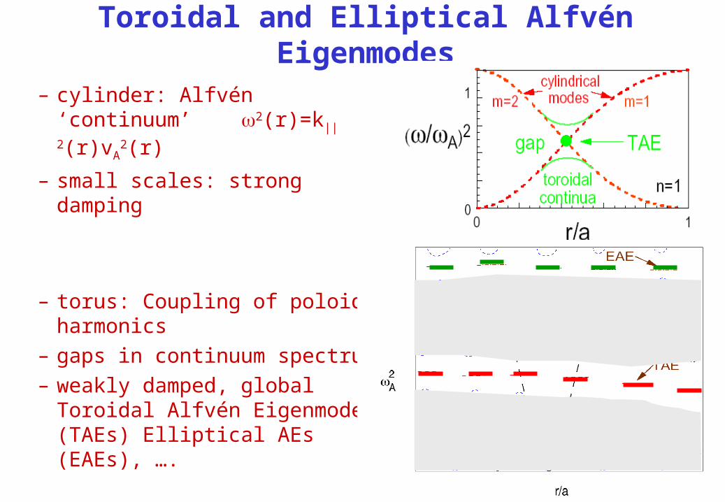
Toroidal and Elliptical Alfvén Eigenmodes
– cylinder: Alfvén ‘continuum’ 2(r)=k||
2(r)vA2(r)
– small scales: strong damping
– torus: Coupling of poloidal harmonics
– gaps in continuum spectrum– weakly damped, global Toroidal
Alfvén Eigenmodes (TAEs) Elliptical AEs (EAEs), ….
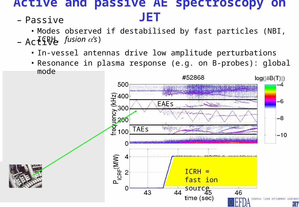
– Active• In-vessel antennas drive low amplitude perturbations• Resonance in plasma response (e.g. on B-probes): global mode
Active and passive AE spectroscopy on JET– Passive
• Modes observed if destabilised by fast particles (NBI, ICRH, fusion ’s)
EAEs
TAEs
ICRH = fast ion source

AEs (TAEs, EAEs, NAEs, GAEs, kinetic TAEs and EAEs) only stable global modes in Alfvén range
fmeas
dampB
B/d
t (T
/s)
+ ti
me
(s) fTAE
n=1 TAE
Ex.: single n=1 TAE tracking using saddle coils
• No ‘stable’ Alfvén Cascades seen to date

Lay-out of the talk
• Recent results from last campaign using JET saddle coils (1994-2004, now dismantled, >3000 discharges)– TAE vs EAE damping at the edge
• TAE edge damping reproduced by theory• Different scaling of EAE damping with plasma shape and edge shear?
– AE damping in core: difficult to reproduce with present models
• Outlook: the new AE antennas at JET (intermediate n’s)

TAE edge damping : experimental evidence
– Shaping of cross-section increased magnetic shear increased mode conversion strong damping
– Quantitative agreement with gyro-kinetic code PENN– Consistent with observed PNBI threshold for TAE excitation

Consequences of strong edge damping
• Damping in the plasma core can be studied with radially extended low-n AEs only for very low shaping (95<0.35, 95 <1.5), i.e. in limiter plasmas
• Strong dependence of damping on edge conditions and profiles – Example: difference in measured damping due to B-field
reversal

TAE damping: effect of B-field direction– Damping of n=1 TAE about 2-3 times larger for reverse B-field (ion
B-drift directed toward X-point, favorable for H-mode)– Comparison with ICRH-driven TAEs (n=3-10)
Calculated fast ion drive at the onset of instability
DRIVE(reverseB) > DRIVE(forwardB)
difference decreases with n
• Forward B more TAE unstable• Challenge for fluid/gyro-kinetic
models• Role of plasma edge flows
(ion B-drift direction)?

Consequences of strong edge damping
• Damping in the plasma core can be studied with radially extended low-n AEs only for very low shaping (95<0.35, 95 <1.5), i.e. in limiter plasmas
• Strong dependence of damping on edge conditions and profiles – Extreme sensitivity on details of edge– Comparison with theory partly be inconclusive (small
changes in edge profiles can be invoked), unless we look at • Scalings of measured damping• Comparison of TAE and EAE in similar conditions

TAE vs EAE damping
• Nearly identical discharges
• Ohmic, limited =1.34, <>=0.004
• Constant ne, Te, Bt, Ip
EAE
TAE
TAE
EAE
(%)
f (kH
z)
Time (s)6 7 8 9 10 11
0
1
2
3
150
200
250
300
350
400
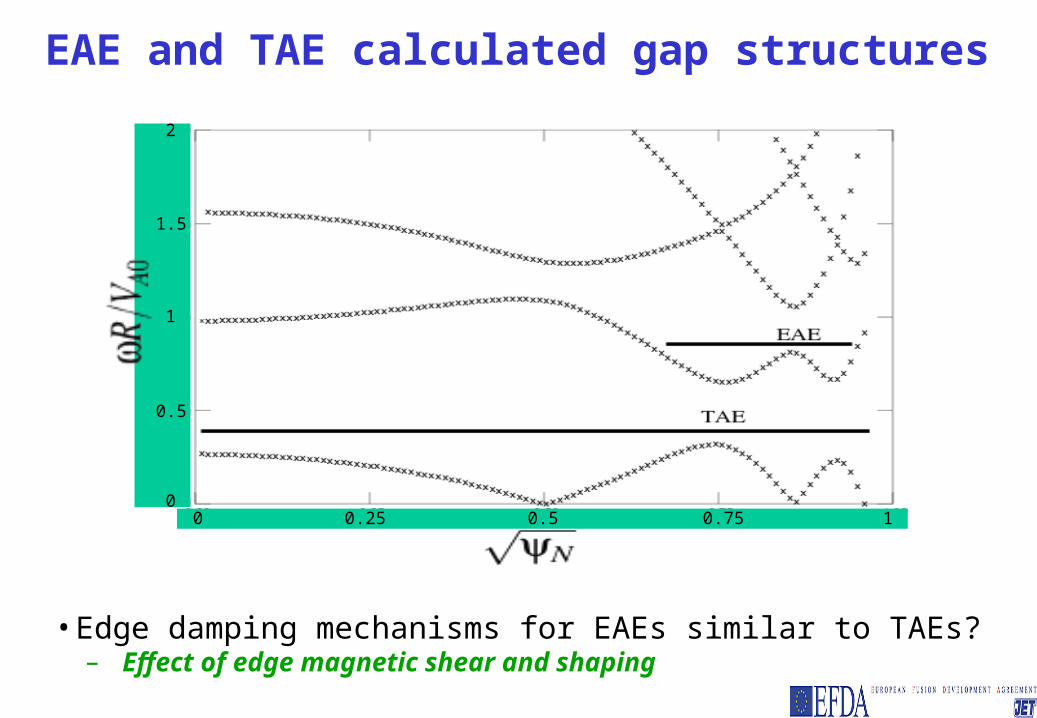
EAE and TAE calculated gap structures
• Edge damping mechanisms for EAEs similar to TAEs?– Effect of edge magnetic shear and shaping
0 0.25 0.5 0.75 1
0.5
1
1.5
2
0

n=1 EAE dampings95 scan from ramping current and shape
3 < s95 < 4.5 scan done during a ramp in Ip and shape
Time (s)
(%)
0 5 10 150
5
1
2
3
2
4
BT (T)Ip (MA)
s95
EAE Damping Rate, #61519
Scan in s95

n=1 EAE damping rate vs s95
2 2.5 3 3.5 4 4.5
1
2
3
4
5
6
7
8
9
s95
(%)
• EAE damping small at high s95
• Similar results for elongation and triangularity
• Opposite to the n=1 TAE trend at high elongation and triangularity
• Hidden q0 dependence?
• Effect of elongation on EAE gap width?

Summary and open questions
• Low-n AE linear stability
– Edge damping
• Large , shape dependence, explained by theory for TAEs
– Extreme sensitivity on edge conditions
» Ex.: effect of B-field reversal on damping and stability
• But EAE damping seems subject to a different scaling
– Effect of q0, gap width dependence on elongation?
– Core damping
• Difficulty in reproducing measured and scalings (see following talks)
– Example of TAE damping dependence on q0

~1500 measurement points for n=1 TAE dampingq0~0.76-1.6, 1.24<95<1.55; 0<95<0.25; 1.35<ne0(1019m-3)<4.2; 1.1<Te0(keV)<5.6; 2.5<q95<4.75
– Transition for q0~1 not reproduced by continuum in CASTOR
TAE damping (in the core?): vs q0

Outlook
• Need to investigate most unstable n range for ITER: n3-15
– Identify systematic methods to compare experiments with theory in intermediate n range (many modes coexisting)
– New AE active antenna on JET
fast ion driven modes: n=3-10
saddle coils: n=0-2• JET saddle coil system limited to low n’s

+ + + +
+ + + _
+ + _ _
+ _ + _
+ _ _ +
+ + _ +
– 45mm from LCFS, 18 turns; i ~ 20A, V~1000V, 10-500kHz– Coupling of n=5 calculated to be as n=2 with saddle coils– Local value of B/B can be larger
~1m
New AE antenna spectrum in-vessel mounting

New AE antenna installed on JET Octant 8


New AE antenna installed on JET Octant 8

Overview of new AE antenna design
18-turns, inconel 718 wire, 4mm diameter,
4mm spacing
distance from LCFS ~45mm: need tiles open frame: no
loop currents
‘wings’ to attach to poloidal limiter
isolating hinges and supports, by-passed by
straps of fixed R to balance halo currents
plug&socket connector
all frame parts are Inconel 625
2 antennas on Octant 4 and Octant 8

Linear mode stability -1- AE damping mechanisms
– Direct ion, electron Landau
– Mode conversion• Directly to shear AW (‘continuum damping’) or to kinetic AW:
– large up to ~ 5-10 %
• Tunneling to shear AW or kAW: ‘radiative damping’
– Collisional damping
• el. coll/ (e/)1/2 e ~ ne / Te 3/2
TAE
=kvA (r)
=kvA(r)TAE