bureau of indian standards delhi 110002 phones … · drafts in wide circulation document despatch...
TRANSCRIPT
प्रलेख पे्रषण संज्ञापन तकनीकी समितत ईटी 09 पे्रषती : 1. ईटीडी 09 के सभी सदस् य 2. विद्युत तकनीकी विभाग परिषद के सभी सदस् य ताा 3. रूचि िखने िाले अन् य सभी िनकाय महोदय , कृप् या िन नललखखत मसौदे की एक प्रित संलग् न ह :
प्रलेख कीषीक
ईटीडी 09(11032) 1100 िोल्टस तक एि ंसहहत कायीकािी िोल्टता की ह लोजन मुक्त ज्िाला विमंदक (HFFR) केबलें - विलकिट
कृप् या स मसौदे का अिलोकन किें ि अपनी समितया यह बतात ेहुए भेजें क अंतत यहद ये मानक के रूप मे प्रकालकत हो जाए तो स पि अमल किने में आपके व् यिसाय अािा कािोबाि में क् या कहाना या आ सकती ह। समितया भेजने की अंितम तािीख: 05-09-2017 . समितया यहद कोई हो तो कृप् या अगले पिृ ा पि हदए प्र में अोोहस् ताक्षरीिी को रपरिललखखत पत ेपि भेज दें यहद कोई समित प्राप्त नहीं होती अािा समित में केिल भाषा संबंोी ्र ुहट हुई तो रपिोक् त प्रलेख को यााित अंितम रूप हदया जाएगा यहद कोई समित तकनीकी प्रकृित की हुई तो विषय सलमित के अध्यक्षरी के पिामकी से अािा रनकी च्छा पि आगे की कायीिाही के ललए विषय सलमित को भेजे जाने के बाद प्रलेख को अंितम रूप दे हदया जाएगा 1 ोन् यिाद,
भिदीय,
(िाजीि कमाी) ि ज्ञािनक ‘ई’ एिं प्रमुख (ईटीडी ) ईमेल [email protected] संलग्न :रपिोक्त
BUREAU OF INDIAN STANDARDS
Manak Bhavan, 9 Bahadur Shah Zafar Marg New
Delhi 110002
Phones 2323 0131 2323 3375 Extn 4284
TeleFax +91 11 2323 1192
Website : www.bis.org.in
email : [email protected]
व् यापक परििालन में मसौदे
संदर्भ
ददनााँक
ईटीडी 09/ टी - 124 06-07-2017

DRAFTS IN WIDE
CIRCULATION
DOCUMENT DESPATCH ADVICE
Reference Date
ETD 09 /T- 124 06-07-2017
TECHNICAL COMMITTEE ETD 09
------------------------------------------------------------------------------------------------------------------------
ADDRESSED TO:
1. All Members of ETD 09
2. All Members of Electrotechnical Division Council; and
3. All other Interested.
Dear Sir(s),
Please find enclosed a copy of the following draft Indian Standard:
Doc No. Title
ETD 09(11032)
HALOGEN FREE FLAME RETARDANT (HFFR) CABLES FOR
WORKING VOLTAGES UPTO AND INCLUDING 1100 VOLTS –
SPECIFICATION
Kindly examine the draft standards and forward your views stating any difficulties which you are likely to
experience in your business or profession, if these are finally adopted as Indian Standards.
Comments, if any, may please be made in the format given overleaf and mailed to the undersigned.
Last date for comments: _05-09-2017.
In case no comments are received or comments received are of editorial nature, you will kindly permit us
to presume your approval for the above documents as finalized. However, in case of comments of
technical in nature are received then it may be finalized either in consultation with the Chairman,
Sectional Committee or referred to the Sectional Committee for further necessary action, if so desired by
the Chairman, Sectional Committee.
Thanking you,
Yours faithfully
(Rajeev Sharma)
Sc ‘E’ & Head (Electrotechnical)
Email: [email protected]
Encl : See attachment.
BUREAU OF INDIAN STANDARDS
Manak Bhavan, 9 Bahadur Shah Zafar Marg
New Delhi 110002
Phones 2323 0131 2323 3375 Extn 4284
TeleFax +91 11 2323 1192
Website : www.bis.org.in
email : [email protected]

BUREAU OF INDIAN STANDARDS Manak Bhavan, 9 Bahadur Shah Zafar
Marg New Delhi 110002 Phones 2323 0131 2323 3375 Extn 4284 TeleFax +91 11 2323 1192 Website : www.bis.org.in email : [email protected]
Date Document No.
06-07-2017 Doc: ETD 09(11032)
Sl. No. Name of the
Organization
Clause/
Sub-
clause
Paragraph/
Figure/Table
Type of
Comment
(General/
Technical/
Editorial
Comments Proposed
Change

Doc ETD 09(11032)
BUREAU OF INDIAN STANDARDS
DRAFT FOR COMMENTS ONLY
(Not to be reproduced without the permission of BIS or used as a STANDARD)
Draft Indian Standard
HALOGEN FREE FLAME RETARDANT (HFFR) CABLES FOR WORKING VOLTAGES
UPTO AND INCLUDING 1100 VOLTS –SPECIFICATION
Last date for receipt of comments is: 05-09-2017_
Power Cable Sectional Committee, ETD 09
FOREWORD
This Indian Standard is proposed to be adopted by the Bureau of Indian Standard after the draft
finalized by the Power Cable Sectional Committee has been approved by the Electro technical
Division Council.
In the formulation of this standard, assistance has been derived from the following standards:
IS / IEC / BS /BSEN Pub. Title
IS 694 : 2010 PVC insulated unsheathed and sheathed cables / cords
with rigid and flexible conductor for working voltage
upto and including 1100 V with amendments
IEC 60227 part 1 to 5 PVC insulated cables of rated voltages up to and
including 450/750V
IEC 60228 ( 2004-11) Conductors of insulated cables
BS 6500 : 1984 Insulated flexible cords and cables
BS EN 50363 – 7 :2005 Halogen Free, thermoplastic, insulating compound
IEC 60092-351 Insulating materials for shipboard and off shore units,
power, Control, instrumentation, telecommunication
and data cables
BS EN 50363-8:2005 Halogen free, thermoplastic, sheathing compound
BS EN 50525-1:2011 Electric Cable – Lowvoltage energy cables of rated
voltages Up To and including 450/750V- Part 1
BS EN 50267-2 Determination of degree of acidity of gases for
materials by Measuring pH and conductivity
BS 7655- part 6.1 Thermoplastic sheathing compounds having low
emission of Corrosive gases and suitable for use in
cables having low Emission of smoke when affected
by fire

BS 7655- part 8 Crosslinked sheathing compounds having low
emission of Corrosive gases and suitable for use in
cables having low Emission of smoke when affected
by fire
IEC 60684 -2 Flexible insulation sleeving – Test method
For the purpose of deciding whether a particular requirement of this standard is complied with,
the final value, observed value, or calculated value expressing the result of a test shall be
rounded off in accordance with IS 2-1960*. The number of significant places retained in the
rounded off value should be the same as that of the specified value in this standard.
Doc: ETD 09(11032)
Draft Indian Standard
HALOGEN FREE FLAME RETARDANT (HFFR) CABLES FOR WORKING
VOLTAGES UPTO AND INCLUDING 1100 VOLTS
1. SCOPE
This specification covers general requirements of single and multicore cables / cords with rigid
as well as flexible annealed bare/tinned copper and aluminium conductor insulated and sheathed
(if any) with Thermoplastic or Cross linked Halogen Free Flame Retardant (HFFR) material for
voltages up to and including 1100 volts AC , 50 Hz, used in power and lighting installations
including cables for low temperature applications. These cables may be used on DC systems for
rated voltages up to and including 1500 volts to earth. These cables are suitable to use for
conductor temperature not exceeding 70O C for thermoplastic or 90°C for cross linked material . NOTES
1 The term cord is used for the flexible cables up to 5 cores covering sizes up to 2.5 Sq.mm.
2 Cables covered in this standard are suitable for indoor use only.
3 The following types of cables are not covered in this standard. They are
a) Telephone cables,
b) Data transmission cables,
c) Instrumentation cables and
d) Screened communication cables.
4 The test specified in section 1, 2 and 3 of this specification shall meet the requirements
specified in IS 8130 : 2013 for conductors, Annex 1 & 2 for HFFR insulation and
sheath are tested as per the test methods given in relevant parts of IS 10810
and those specifically specified in this specification.
5. This standard covers the following catagories of cables.
Category code Cable description
01 Thermoplastic 70OC
02 Thermoplastic 90OC ( Sheath only )
03 Crosslinked 70OC
04 Crosslinked 90OC
6 This specification is divided into the following three sections :
Section –1 : General Requirements
Section– 2: Unsheathed Single core cables/cords for fixed and flexible wiring
Section– 3: Sheathed/ Unsheathed single and multi core cables/cords for
fixed and flexible wiring.

2. REFERENCES
The standards listed below contain provisions which through reference in this text,
constitute provisions of this standard. At the time of publication, the editions indicated
were valid. All standards are subject to revision and parties to agreements based on
this standard are encouraged to investigate the possibility of applying the most recent
editions of the standards listed below:
IS Title
1885 ( Part 32) 1971 Electrotechnical Vocabulary: part
32 cables, conductors and
Accessories for electricity supply
IS 4905 : 1968 Methods for random sampling
IS 8130 : 2013 Specification for conductors for
Insulated electric cables and
Flexible cords
IS10810 – Methods of test for cables
(Part 0 ) : 1984 General
(Part 1) : 1984 Annealing test for wires used in
conductors
(Part 2) : 1984 Tensile test of Aluminium Wires
(Part 3) : 1984 Wrapping test for aluminium wires
(Part 4) : 1984 Persulphate test for tinned copper
(Part 5) : 1984 Conductor Resistance test
(Part 6) : 1984 Thickness of insulation and sheath
(Part 7) : 1984 Tensile strength and elongation
(Part 11) : 1984 Ageing test
(Part 12) : 1984 Shrinkage test
(Part 13) : 1984 Ozone resistant test
(Part 15) : 1984 Hot deformation test
(Part 20) : 1984 Cold bend test
(Part 21) : 1984 Cold impact Test
(Part 30) :1984 Hot set test
(Part 43) : 1984 Insulation resistance test.
(Part 44) : 1984 Spark test.
(Part 45) : 1984 High Voltage Test
(Part 53) : 1984 Flammability Test
(Part 58) : 1998 Limited Oxygen index Test

(Part 59) : 1988 HCL Emission Test
(Part 61) : 1988 Flame Retardant Test
(Part 62) : 1993 Flame Retardant Test for bunched cable
(Part 63) : 1993 Smoke density test
(Part 64) : 2003 Temperature index Test
NOTE ― In case of above reference standard, editions of these publications current at the time of the issue of this standard are incorporated, but references should be made to the latest editions only.
3. TERMINOLOGY
For the purpose of this standard, the definitions given in IS1885 (Part 32) : 1971 and IS 10810
(Part 0) : 1984 shall apply further to the following.
3.1 Rated voltage ― Rated voltage U0 being the r.m.s Voltage between any insulated conductor
and earth.
Rated Voltage U being the r.m.s Voltage between any two-phase
conductors of multi core cable.
3.1.2 Definitions related to insulated and sheathing material
3.1.2.1 Halogen Free Flame Retardant compound (HFFR)
Combination of materials suitably selected, proportioned and treated of which
characteristics constituent is the halogen free flame retardant plastomer or one of its
co-polymers. The same term also designates compounds containing halogen free
flame retardant polymers and some of its co-polymers.
3.1.2.2 Type of compounds
The category namely Thermoplastic OR Thermoset (Crosslinked) in which
compound is placed according to its properties, as determined by specific tests. .
3.2 Routine Tests ― Tests made by manufacturer on all finished cable lengths to demonstrate
the integrity of the cable.
3.3 Acceptance Tests ― Tests carried out on sample taken from a lot for the purpose of
acceptance of the lot.
3.4 Type Tests ― Test required to be made before supplying a type of cable covered by this
standard on a general commercial basis in order to demonstrate satisfactory performance
characteristics to meet the intended applications. These tests are of such a nature that after they
have been made, they need not be repeated unless changes are made in the cable materials or
design or manufacturing process, which might change the performance characteristics.
3.5 Nominal Value ― The value by which a quantity is designated and which is often used in
tables. Usually in this standard, nominal values give rise to values to be checked by
measurements taking in to account specified tolerences.
SECTION 1 GENERAL REQUIREMENTS
4 MATERIAL
4.1 Conductor
4.1.1 Material
a) The conductors shall be composed of annealed Bare or tinned of high
conductivity copper wires or Aluminium complying to IS 8130 : 2013
b) A separator tape made of suitable Halogen free material applied over
conductor at the discretion of the manufacturer.
c) Electrical resistance – The resistance of conductor at 20°C per Km shall be
in accordance with the requirements specified in relevant tables of IS 8130
: 2013 for the given class of conductor and tested as per IS 10810 part 5.
d) The classes of the conductors relevant to the various types of cables are
given in respective sections of this specification namely Section 2 and
Section 3.
e) Conductors of cables for fixed installation shall be circular solid or circular
stranded or compacted circular or stranded sector shaped.
f) Nominal cross sectional area of conductor of cables covered in this standard
are given in respective tables.
4.2 Insulation 4.2.1 The insulation shall be either Thermoplastic or Cross linked halogen free
flame retardant (HFFR) compound conforming to the requirements specified in Annex
1 of this specification.
Type HFI -TP 70 (Thermoplastic) with rated temperature of 70°C and Type HFI- XL
70 / HFI- XL 90 Cross linked ( Thermoset ) with rated temperature of 70o C /90°C
4.2.2 Application to the conductor
The insulation shall be so applied that it fits closely on the conductor. It shall be
possible to remove it without damage to the insulation itself, to the conductor or to the
tin coating if any. Compliance shall be checked by inspection and by Visual
Inspection.
4.2.3 Thickness
The mean value of the thickness of insulation shall be not less than the specified
nominal value for each type and size of cable shown in the relevant tables given in
Section 2 and 3 of this specification.
The smallest of the measured values of thickness of insulation (ti) shall not fall below
the nominal value (ti) specified in the relevant table by more than (0.1 mm +0.1 ti).
4.2.4 Mechanical properties before and after ageing
The insulation shall have adequate mechanical strength and elasticity within the
temperature limits to which it may be exposed in normal use.
The compliance shall be checked by carrying out tensile strength and elongation test,
for respective type of compound, as per method given in IS 10810-Part 7. The
applicable test values shall be obtained from Annex 1, for appropriate type of
compound.

4.3 Fillers
4.3.1 The fillers, if provided, shall be of Halogen Free Flame Retardant Material.
4.3.2 The filler materials shall be suitable for operating temperature of the cable and
compatible with other components of the cable. This shall not be harder than the
HFFR material used for insulation and sheath.
4.4 Binder Tape
Binder tape if required, shall also be of suitable material of halogen free in nature.
4.5 Sheath
4.5.1 The sheath shall consist of Halogen Free Flame Retardant Compound
conforming to the requirements of HFS-TP 70 or HFS-TP 90 or HFS – XL 70 or
HFS- XL 90 given in annex 2 of this specification.
Notes : 1. Insulation and sheath material shall be compatible with each other as per the temperature
rating of the cable.
2. A combination of cross linked insulation and thermoplastic sheath is also permissible 4.5.2 Application
The sheath shall be applied in a single layer :
a) On the core, in the case of single-core cables;
b) On the assembly of cores and fillers or inner covering, if any, in the case
of other cables.
The sheath shall not adhere to the cores. A separator, consisting of a film or tape, or
talcum powder may be placed under the sheath. This separator shall be compatible
with the insulation and sheath materials.
4.5.3 Thickness
The mean value of the thickness of sheath shall not be less than the specified nominal
value for each type and size of cable shown in the tables of the particular specifications
(Section 3 of this specification).
However, the thickness of sheath determined by taking average of number of
measurements shall be not less than nominal value (ts) specified in relevant Tables and
smallest of the measured value shall not fall below the nominal value (ts) specified by
more than 0.15 ts + 0.1 mm for Single Core Cables and 0.2 ts. + 0.2 mm. for
Multicore cables.
Compliance shall be checked by testing the dimensional requirements specified in
section 2 & 3 and as per test method given in IS 10810 (Part 6) : 1984
4.5.4 Mechanical properties before and after ageing
The sheath shall have adequate mechanical strength and elasticity within the
temperature limits to which it may be exposed in normal use.
The compliance shall be checked by carrying out tensile strength and elongation test,
shall meet the requirements given in Annex 2.
4.5.5 Overall dimensions
The maximum overall dimensions of the cables shall be within the limits specified in
the tables 3 to 8 given in Section 2 & 3 of this specification.

4.5.5.1 Ovality
The difference between maximum and minimum measured values of overall diameter
of sheathed circular cables shall not exceed 15 percent of the maximum measured
value at the same cross section.
4.5.6 Colour of sheath
The colour of sheath shall be black or in any colour as agreed to between the purchaser
and the supplier.
5. TESTS
The testing on the cables will be conducted as given Table 2. For each category of
cables listed under scope of this standard.
Unless otherwise stated, the tests shall be carried out in accordance with appropriate
part of IS 10810, taking into account the additional information given in this standard.
5.1 High Voltage Test, (at Room. Temperatures) (Acceptance and Routine Test)
In case of multicore cables and cords test voltage shall be applied for a period of 5
minutes between the cores.
Single-core cables shall be immersed in water at ambient temperature one hour before
the testing and the test voltage shall be applied between conductor and water. for the
specified period
Cables / cords tested as above shall withstand without breakdown an ac voltage of 3
kV (rms) or a dc voltage of 7.5 kV for 5 minutes.
5.2 Spark Test (Routine Test)
Spark test may be carried out as an alternate to high voltage on single core unsheathed
cables. The voltage shall be as specified below:
Thickness of Insulation(mm) Test Voltage KV (rms)
Up to and including 1.0 6
Above 1.0 and up to and including 1.5 10
Above 1.5 and up to and including 2.0 15
Above 2.0 and up to and including 2.5 20
Above 2.5 25
5.3 Flammability Test
The test shall be conducted as per IS 10810 (Part 53)
The period of burning after removal of flame shall not exceed 60 seconds and the
unaffected (un charred) portion from the lower edge of the top clamp shall be at least
50 mm.
5.4 Oxygen index test
The test shall be conducted as per IS 10810 (Part 58) on samples at 27 +/-2°C.
The oxygen index shall not be less than 31. Note : "This test is not applicable for cable produced with Cross linked compounds"

5.5 Test for temperature index
The test shall be conducted as per IS 10810 (Part 64).
The minimum measured value of temperature index shall be 250°C at which the
oxygen index is 21. Note : "This test is not applicable for cable produced with Cross linked compounds"
5.6 Smoke density
The test shall be conducted as per IS 10810 (Part 63). Minimum Transmittance of light
shall be 70 percent.
5.7 Assessment of Halogen
This test is done to determine the presence of halogen and to sequential test
programme as given in table 1 of Annex 4. The detailed step by step sample testing
sequence as per table 2 of Annex.4. .
5.8 Determination of Elements of halogen presents
This test is done to determine the elementsof halogen present and sequential test
programme as given in table1 of Annex.4. the detailed step by step sample testing
sequenc to table 2 of Annex. 4.
5.9 Degree of acidity of combustion gases
This test is done to determine the degree of acidity of combustion gasses for materials
by measuring pH and conductivity. For details refer annex 6.
5.10 Toxicity index test – Under consideration.
5.11 Flex Test – Under consideration.
5.12 Persulphate Test
The Tinned copper used in conductor shall meet the requirement as specified in IS
8130 and test conducted as per IS 10810 – 4
5.13 Flame retardant test
The test shall be conducted as per IS 10810 (Part 61) on single core cable and after the
test, there should be no visible damages on the test specimen within 300 mm from its
upper end.
5.14 Hot set Test
The insulation of heat resistance cross linked HFFR (HFI-XL70,HFI-XL
90,HFSXL70, HFS XL 90) cable are subjected to Hot set test and the elongation
percent under load shall be maximum 175 percent and Permanent set shall be
maximum 15 percent and tested as per IS 10810 – 30
5.15 Water Immersion Test (Effect of water on Sheath):
This test represents the influence of water on the mechanical properties of sheath
through tensile strength and elongation at break on untreated and treated samples after

water immersion. The test results on the conditioned and unconditioned samples shall
not have any significant change. The test samples are immersed into the de-ionized
water for the temperature and duration as specified in 7 of Annex 2. After the water
immersion the sample shall be cooled off to 20±5°C before taken out of water. The
test samples are removed off the moisture using Tissue paper and the tensile strength
and elongation at break tests are conducted within 40 minutes as IS 10810-7.
5.16 Ozone Resistance Test :
This test shall be conducted as per IS 10810-13.
5.17 Cold Bend Test :
This test shall be conducted as per IS 10810-20.
5.18 Cold Impact Test :
This test shall be conducted as per IS 10810-21.
6. CORE IDENTIFICATION BY COLOUR
Each core shall be identified as given below:
a) In case of cables for fixed wiring up to and including 4 core shall be as per
Table1,
b) The flexible cables / cords having up to and including 25 cores shall be marked
as per the colour scheme given in Table1, and
c) Any other scheme agreed between the Purchaser and Manufacturer shall be
permitted.
6.1 General requirements
Identification of the cores of a cable shall be achieved by the use of coloured insulation
or other suitable method (as per Table 1). The colouring with skin type is allowed
provided it meets the desired testing as given in the specification.
The colours shall be clear, identifiable and durable. Durability shall be checked by the
test given in 6.2.2.
6.1.1 Colour combination green-and-yellow
In case of Yellow-Green cables used for earthing, the distribution of the colours shall
comply with the following condition:
For every 15 mm length of core, one of these colours shall cover at least 30 percent
and not more than 70 percent of the surface of the core, the other colour covering the
remainder.
6.2 Core identification by numbers

In case of core identification with help of numbering instead of colour identification
following shall be applicable.
The insulation of the cores shall be of the same colour preferably in black and
numbered sequentially, except for the core coloured green-and-yellow, if one is
included.
The green-and-yellow core, if any, shall comply with the requirement of 6.1.1 and
shall be in the outer layer, as last core.
The numbering shall start by number 1 in the inner layer.
The numbers shall be printed in Indo-Arabic numerals on the outer surfaces of the
cores. All the numbers shall be of the same colour, which shall contrast with the
colour of the insulation. The numerals shall be legible.
6.2.1 Preferred arrangement of marking
The numbers shall be repeated, at regular intervals along the core, consecutive
numbers being inverted in relation to each other.
When the number is a single numeral, a dash shall be placed underneath it. If the
number consists of two numerals, these shall be disposed one below the other and a
dash placed below the lower numeral. The spacing between consecutive numbers shall
not exceed 50 mm.
6.2.2 Durability
Printed numerals shall be durable. Compliance with this requirement shall be checked
by gently rubbing the print using wet cloth 10 times without generating heat locally.
The print shall still remain clear and legible.
7. CABLE CODE
Constituent Code Letter
Aluminium conductor A
HFFR thermoplastic insulation Z
HFFR thermoplastic sheath Z
HFFR thermoset insulation XZ
HFFR thermo set sheath XZ
Note : No code letter for conductor is required when the conductor material is
Copper.
1
50 mm
Max. 50 mm
Max.
2
1
2 1
2
8. SAMPLING OF CABLE
Refer to Annex 3 of this specification
9. IDENTIFICATION AND MARKING ON THE CABLE
9.1 General Requirement:-
The manufacturer shall be identified throughout the length of the cable by
manufacturers name or trade-mark being printed intended or embossed on the
insulation in case of single core cable and on the sheath in case of sheathed cable. In
case none of these methods can be employed, or the purchaser so desires, colour
identification threads in accordance with the scheme to be approved by BIS shall be
employed which shall be free from halogen content. The Distance between two
consecutive prints shall not greater than 1000mm.
Further to above following parameters can be either printed, intended or embossed
over insulation in case of single core cable or over sheath in case of multi core cable
a) No. of Cores and Cross sectional area of the conductor in Sq.mm,
b) BIS Licence number
c) BIS standard number and mark.
d) Cable code and
e) year of manufacture.
The Marking shall be legible and indelible and it shall be checked, as per 6.2.2
10. PACKING AND MARKING
10.1 The cable shall ‘be either wound on drum, reels or supplied in coils
10.2 The cable (packed in coil, reel or drum) shall carry the following information
either stenciled on the reel or drum or contained in a label attached to it
a) Reference to this Indian Standard and BIS mark.
b) Manufacturer’s name, brand name or trade mark
c) Type of cable and voltage grade
d) Nominal cross-sectional area of conductor
e) Cable code
f) Colour of core (in case of single core cables)
g) Length of cable on the reel, drum or coil
h) Number of lengths on the reel, drum or coil (if more than one)
i) Direction of rotation of drum (by means of arrow )

j) Country of manufacture
k) Year of manufacture
Table 1 Core Identification
(Clause 6)
No.of
cores
(1)
Cables for
fixed wiring
(2)
Flexible cords
(3)
1 Red, Black,
Yellow, Blue,
White or Grey
Red, Black, Yellow, Blue, White, Grey or Green-
Yellow
2 Red & Black Red & Black
3 Red, Yellow &
Blue
Red, Black and Yellow-Green or Red, Yellow and
Blue
4 Red, Yellow,
Blue and Black
Red, Yellow, Blue and Yellow-Green or Red,
Yellow, Blue and Black
5 - Red, Yellow, Blue, Black and Grey or Yellow,
Blue, Green White and Yellow-Green
6 - Red, Yellow, Blue, Green, White and Yellow-
Green Alternatively insulated cores shall be of
same colour preferably black or grey or any other
colour in agreement with purchaser and the
manufacturer with number coded and with yellow
green core in outer most layer if required
7 - Red, Yellow, Blue, Green, White, Black and
Yellow-Green Alternatively insulated cores shall
be of same colour preferably black or grey or any
other colour in agreement with purchaser and the
manufacturer with number coded and with yellow
green core in outer most layer if required
8 - Red, Yellow, Blue, Green, White, Black, Grey and
Yellow-Green Alternatively insulated cores shall
be of same colour preferably black or grey or any
other colour in agreement with purchaser and the
manufacturer with number coded and with yellow
green core in outer most layer if required
9 Red, Yellow, Blue, Green, White, Black, Grey,
Yellow-Green, Orange/Brown Alternatively
insulated cores shall be of same colour preferably
black or grey or any other colour in agreement
with purchaser and the manufacturer with number
coded and with yellow green core in outer most
layer if required
10 - Red, Yellow, Blue, Green, White, Black, Grey,
Yellow-Green, Orange and Brown Alternatively
insulated cores shall be of same colour preferably
black or grey or any other colour in agreement
with purchaser and the manufacturer with number
coded and with yellow green core in outer most
layer if required

11 Red, Yellow, Blue, Green, White, Black, Grey,
Orange, Brown, Pink and Yellow- Green
Alternatively insulated cores shall be of same
colour preferably black or grey or any other
colour in agreement with purchaser and the
manufacturer with number coded and with yellow
green core in outer most layer if required
12 - Red, Yellow, Blue, Green, White, Black, Grey,
Orange, Brown, Pink , Violet and Yellow- Green
Alternatively insulated cores shall be of same
colour preferably black or grey or any other
colour in agreement with purchaser and the
manufacturer with number coded and with yellow
green core in outer most layer if required
13-
25
- Two adjacent cores in each layer Blue & Yellow
(counting & direction core), and other remaining
cores – Grey with or without number printing.
Alternatively insulated cores shall be of same
colour preferably black or grey or any other
colour in agreement with purchaser and the
manufacturer with number coded and with yellow
green core in outer most layer if required
-
NOTES
1. In case of single-core cables used for control wiring of switchgear, any colour
other than the above shall be permissible as agreed to between the Purchaser and
the Supplier.
2. The colour of insulation for parallel twin flexible cords may be any two of Red,
Black, Yellow, Blue, White and Grey. The cores may be identified by a
longitudinal rib on one core in case of same colour of the cores.
4. For cables and cords with more than five cores, as an alternative, it is permissible
to have all cores of the same colour. In such case, the cores shall be numbered
sequentially (Hindu-Arabic numerals printed on the surface of the cores), starting
with “1” for the innermost layer. The gap between two successive printings shall
not exceed 50 mm.
Table 2 Type of Tests
(Clause 14.7)
Test
(1)
For Requirements
Ref.
(2)
For Test
Method,
Ref. Part
No. of
IS 10810
(3)
Category
( 4)
I Routine Tests

A) HV Test Or Cl 5.1 45 01,02,03,04
Spark Test Cl.5.2 44
B) Conductor Resistance Test 20°C CL.4.1.1(c) 5 01,02,03,04
II Acceptance Test
A) Tensile test (for aluminium) IS 8130 : 2013 2 01,02,03,04
B) Wrapping test (for aluminium) IS 8130 : 2013 3 01,02,03,04
C) Persulphate test for Tinned
copper
IS 8130 : 2013 4 01,02,03,04
D) Conductor Resistance test IS 8130 : 2013 5 01,02,03,04
E) Test for thickness of insulation
and sheath,
diameter of core and sheath
including ovality of sheath
Cl 11.2, 11.3,
12.2,12.3,13.2, 13.4,
13.5,13.6, 14.2,14.4,14.5,
14.6, 15.2,,15.4, 15.5 and
Table 3 to 8
6 01,02,03,04
01,02,03,04
01,02,03,04
F) Tensile strength and Elongation
at break of insulation and sheath
Annexure 1 & 2 7 01,02,03,04
G) Insulation resistance Annexure 1 43 01,02,03,4
H) High voltage test Cl.5.1 45 01,02,03,04
I) Flammability test Cl.5.3 53 01,02,03,04
J) pH and Conductivity
K) Hot set Test
Cl.5.9 & Annexure 6
Annexure 1
-
30
01,02,03,04
03,04
III Type Test
A. Conductor
1) Conductor Resistance Test IS 8130 : 2013 5 01,02,03,04
2) Annealing test (for copper) IS 8130 : 2013 1 01,02,03,04
3) Persulphate test for Tinned copper IS 8130 : 2013 4 01,02,03,04
4) Tensile test (for aluminium) IS 8130 : 2013 2 01,02,03,04
5) Wrapping test for
aluminium)
IS 8130 : 2013 3 01,02,03,04
B) Test for overall dimensions
and thickness of insulation
and sheath
Cl 11.2, 11.3,
12.2,12.3,13.2, 13.4,
13.5, 13.6, 14.2,14.4,
14.5, 14.6, 15.2,15.4, 15.5
and
Table 3 to 8
6 01,02,03,04
C) Tests on Insulation
1)Tensile strength and elongation
at break Before and after
ageing
Annexure 1
7 & 11
01,02,03,04
2) High voltage test Cl.5.1 45 01,02,03,04
3) Insulation resistance Annexure 1 43 01,02,03,04
4) Oxygen index Cl.5.4 58 01,02
5) Temperature Index Cl.5.5 64 01,02
6) Ageing in air oven Annexure 1 11 01,02,03,04
7) Hot deformation Annexure 1 15 01,02,03,04
8) Assessment of halogen Annexure 4 & 5 - 01,02,03,04
9) pH and Conductivity Cl.5.9 & Annexure 6 - 01,02,03,04
10) Cold Bend Test Annexure 1 20 01,02,03,04
11) Cold Impact Test Annexure 1 21 01,02,03,04
12) Hot set Test Annexure 1 30 01,02,03,04
13) Ozone Resistance Test Annexure 1 13 01,02,03,04

14)Flame retardant test Cl.5.13 61 01,02,03,04
D) Tests on Fillers / Dummy
cores and Binder tapes /
identification Threads ( if
Any)
1) pH and Conductivity Cl.5.9 & annexure 6 -
01,02,03,04
2) Assessment of halogen Annexure 4 & 5 - 01,02,03,04
E) Tests on Sheath
1)Tensile strength and
elongation at break
Annexure 2
7
01,02,03,04
2) Ageing in air oven Annexure 2 11 01,02,03,04
3) Oxygen index Cl.5.4 58 01,02
4) Temperature Index Cl.5.5 64 01,02,
5) Ozone Resistance Test Annexure 1 13 01,02,03,04
6) Hot deformation Annexure 2 15 01,02,03,04
7) pH and Conductivity Cl.5.9 & annexure 6 -
01,02,03,04
8) Assessment of halogen Annexure 4 & 5 - 01,02,03,04
F) Tests on Finished cable
1) High Voltage test
Cl.5.1
45
01,02,03,04
2) Flammability test CL.5.3 53 01,02,03,04
3) Cold bend test Annexure 1&2 20 01,02,03,04
4) Cold impact test Annexure 1&2 21 01,02,03,04
5) Flame retardant test CL.5.13 61 01,02,03,04
6) Water immersion test of cable
7) ) Smoke density test
Cl.5.15
Cl. 5.6
-
63
01,02,03,04
01,02,03,04
SECTION 2
UN SHEATHED SINGLE CORE CABLES / CORDS
FOR FIXED AND FLEXIBLE WIRING
11.0 Single Core un-sheathed cables with rigid conductor (Class 1 or 2) ( Maximum
conductor temperature 70°C or 90°C)
11.1 Construction
Conductor shall comply with requirements of IS 8130 : 2013 Class- 1 for solid, and
Class-2 for stranded conductor
Sizes covered - 0.5 to 10.0 mm² – Class 1 & 2
- 16 mm² and above – Class 2
NOTE ― In case of Aluminium conductor cables, construction of 4.0 mm² and above only considered.
11.2 Insulation
Insulation shall be Halogen free flame retardant compound type HFI-TP 70 or HFI-
XL 70 or HFI-XL 90 as per annexure 1, applied around conductor by the extrusion
process . The thickness shall comply with the specified values given in column 2 of
Table 3.

The smallest of the measured values of thickness of insulation shall not fall below
the nominal value (ti) specified in the Table No. 3 by more than (0.1 mm +0.1 ti).
11.3 Overall Diameter
The maximum overall diameter shall not exceed limits given in column 3 of Table 3.
11.4 Tests
Compliance with the requirements of 11.1 to 11.3 above shall be checked by
inspection and by the tests given in Table 2.
Table 3 Dimensions of Single Core Halogen Free Flame Retardant type
un-sheathed cables with rigid conductor (Class-1 or 2) (maximum conductor
temperature 70°C or 90°C)
(Clause 11.2,11.3)
Nominal cross-
sectional area of
conductor
(1)
Class of
conductor
(2)
Thickness of
Insulation
Nom.(ti)
(3)
Max.
overall
diameter
(4)
mm² mm Mm
0.5 1 0.6 2.3
0.75 1 0.6 2.5
1.0 1 0.7 3.1
1.0 2 0.7 3.2
1.5 1 0.7 3.2
1.5 2 0.7 3.3
2.5 1 0.8 3.9
2.5 2 0.8 4.0
4.0 1 0.8 4.5
4.0 2 0.8 4.6
6.0 1 0.8 5.0
6.0 2 0.8 5.2
10.0 1 1.0 6.5
10.0 2 1.0 6.7

16.0 2 1.0 7.8
25.0 2 1.2 9.7
35.0 2 1.2 10.9
50.0 2 1.4 12.8
70.0 2 1.4 14.6
95.0 2 1.6 17.1
120.0 2 1.6 18.8
150.0 2 1.8 20.9
185.0 2 2 23.3
240.0 2 2.2 26.6
300.0 2 2.4 29.5
400.0 2 2.6 33.2
500.0 2 2.8 37.5
630.0 2 2.8 42.0
12.0 SINGLE CORE UN-SHEATHED CABLE WITH FLEXIBLE COPPER
CONDUCTOR (MAXIMUM CONDUCTOR TEMPERATURE OF 70°C OR 90°C)
12.1 Construction
Conductor - The conductor shall comply with the requirements given in IS 8130 :
2013 Class 5 conductors.
Sizes covered – 0.5 to 300 mm²
12.2 Insulation
The insulation shall be Halogen free flame retardant compound HFI-TP 70 or HFI-
XL 70 and HFI-XL 90 as per annexure 1, applied around the conductor by the
suitable process..
The thickness shall comply with specified values given column 2 of Table 4.
The smallest of the measured values of thickness of insulation shall not fall below
the nominal value (ti) specified in the table No. 4 by more than (0.1 mm +0.1 ti).
12.3 Overall diameter
The maximum overall diameter shall not exceed the limit given in column 3 of
Table 4.
12.4 Tests
Compliance with requirement of clause No. 12.1 to 12.3 shall be checked by
inspection and by the test given in Table. 2.

Table 4 Single core Halogen Free Flame Retardant type un-sheathed
cable with flexible conductor
( Maximum conductor temperature 70°C or 90°C)
(Clause 12.2,12.3)
Nominal cross-
sectional area of
conductor
(1)
Thickness of
Insulation
Nom.(ti)
(2)
Max.
overall
diameter
(3)
mm² mm mm
0.5 0.6 2.6
0.75 0.6 2.8
1 0.6 3
1.5 0.6 3.4
2.5 0.7 4.1
4 0.8 4.8
6 0.8 5.3
10 1 7
16 1 8.1
25 1.2 10.2
35 1.2 11.7
50 1.4 13.9
70 1.4 16
95 1.6 18.2
120 1.6 20.2
150 1.8 22.5
185 2 25
240 2.2 28.5
300 2.4 32
SECTION 3
SHEATHED /UNSHEATHED SINGLE AND MULTICORE CABLES / CORDS
FOR FIXED AND FLEXIBLE WIRING
13. Single and multicore circular Halogen Free Flame Retardant (HFFR) insulated and
sheathed cables with rigid conductor (Class 1 & 2) (maximum conductor
temperature 70°C or 90°C )
13.1 Construction
The conductor shall comply with requirements of IS 8130 : 2013 Class 1 for solid and
Class 2 for stranded conductor.
No. of cores – 1, 2, 3, or 4
Sizes – 1.0 to 120 mm²
13.2 Insulation

The insulation shall be of Halogen free flame retardant compound HFI-TP 70 or HFI-XL
70 or HFI-XL 90 applied around the conductor by the suitable process. The thickness
shall comply with specified values given in Table 5.
The smallest of the measured values of thickness of insulation shall not fall below the
nominal value (ti) specified in the relevant table by more than (0.1 mm +0.1 ti).
13.3 Assembly of cores
In case of circular cables with 2 core and above, the cores shall be twisted together to
form core assembly as given in 4.5.
13.4 Sheath
The sheath shall be Halogen free flame retardant compound type HFS-TP 70 or HFS TP
90 or HFS – XL 70 or HFS-XL 90, applied around the laid up cores by the suitable
process . The sheath shall fit closely and shall be capable of being removed without
damage to the inner core. The sheath thickness shall comply with specified values given
in Table 5.
The thickness of sheath determined by taking average (ts)of number of measurements,
shall not be less than nominal value (ts) specified in Table 1 and the smallest of the
measured values shall not fall below nominal value specified in Table No. 5 by more than
0.15 ts + 0.1 mm for Single Core Cables and 0.2 ts. + 0.2 mm. for Multicore cables. The colour of sheath shall be black or any other colour as agreed between the purchaser
and supplier.
13.5 Ovality
The difference between maximum and minimum measured values of overall diameter of
sheathed circular cables shall not exceed 15 percent of the max measured values at the
same cross section.
13.6 Overall dimensions
The maximum overall dimensions shall be within the upper limit as given in Table 5.
13.7 Tests
The compliance with the requirement of 13.1 to 13.5 and shall be checked by inspection
by test given in Table-2.
14. SINGLE AND MULTICORE CIRCULAR HALOGEN FREE FLAME
RETARDANT (HFFR) INSULATED AND SHEATHED CABLES WITH
FLEXIBLE CONDUCTOR (CLASS 5) (MAXIMUM CONDUCTOR TEMPERATURE
70°C or 90°C)
14.1 Construction
No. of conductors – 1, 2, 3 , 4 & 5
The conductors shall comply with requirements given in IS 8130 : 2013 for Class 5.
Sizes covered – 4.00 to 300 mm²
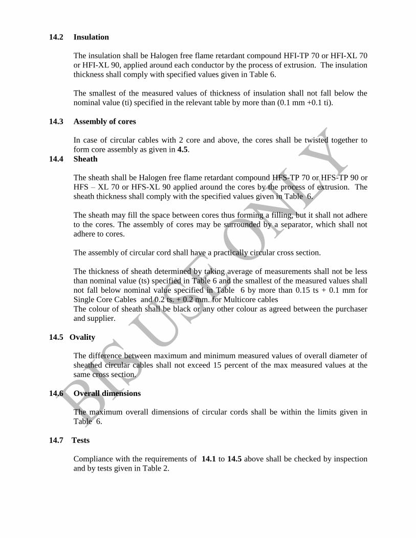
14.2 Insulation
The insulation shall be Halogen free flame retardant compound HFI-TP 70 or HFI-XL 70
or HFI-XL 90, applied around each conductor by the process of extrusion. The insulation
thickness shall comply with specified values given in Table 6.
The smallest of the measured values of thickness of insulation shall not fall below the
nominal value (ti) specified in the relevant table by more than (0.1 mm +0.1 ti).
14.3 Assembly of cores
In case of circular cables with 2 core and above, the cores shall be twisted together to
form core assembly as given in 4.5.
14.4 Sheath
The sheath shall be Halogen free flame retardant compound HFS-TP 70 or HFS-TP 90 or
HFS – XL 70 or HFS-XL 90 applied around the cores by the process of extrusion. The
sheath thickness shall comply with the specified values given in Table 6.
The sheath may fill the space between cores thus forming a filling, but it shall not adhere
to the cores. The assembly of cores may be surrounded by a separator, which shall not
adhere to cores.
The assembly of circular cord shall have a practically circular cross section.
The thickness of sheath determined by taking average of measurements shall not be less
than nominal value (ts) specified in Table 6 and the smallest of the measured values shall
not fall below nominal value specified in Table 6 by more than 0.15 ts + 0.1 mm for
Single Core Cables and 0.2 ts. + 0.2 mm. for Multicore cables
The colour of sheath shall be black or any other colour as agreed between the purchaser
and supplier.
14.5 Ovality
The difference between maximum and minimum measured values of overall diameter of
sheathed circular cables shall not exceed 15 percent of the max measured values at the
same cross section.
14.6 Overall dimensions
The maximum overall dimensions of circular cords shall be within the limits given in
Table 6.
14.7 Tests
Compliance with the requirements of 14.1 to 14.5 above shall be checked by inspection
and by tests given in Table 2.

15. MULTICORE CIRCULAR HALOGEN FREE FLAME RETARDANT (HFFR)
INSULATED AND SHEATHED CORDS/ WITH FLEXIBLE CONDUCTOR (CLASS 5)
(MAXIMUM CONDUCTOR TEMPERATURE 70°COR 90°C )
15.1 Construction
a Conductor material : Annealed bared or tinned copper.
b. No. of conductors – 1,2,3,4,& 5 for cords, 6 to 25 for cables
c. Sizes covered – 0.5 to 2.5 mm² for cords/cables, 0.5 to 4.0 sqmm for twin twisted/ twin
parallel cords/cables.
The conductors shall comply with requirements given in IS 8130 : 2013 for Class 5.
15.2 Insulation
The insulation shall be Halogen free flame retardant compound HFI-TP 70 or HFI-XL 70
or HFI-XL 90, applied around each conductor by the process of extrusion. The insulation
thickness shall comply with specified values given in Table 7 & 8
The smallest of the measured values of thickness of insulation shall not fall below the
nominal value (ti) specified in the relevant table by more than (0.1 mm +0.1 ti).
15.3 Assembly of cores
In case of circular cables with 2 core and above, the cores shall be twisted together to
form core assembly as given in 4.5.
15.3.1 Twisted Twin unsheathed flexible cables/cords The cores shall be twisted together with suitable lay.
15.3.2 Twin Parallel ( unsheathed ) flexible cords
Two conductors shall be laid parallel and insulated simultaneously such that the cores
can be separated readily without damage.
15.3.3 Twin Flat sheathed flexible cables /cords
The recommended lay up of cores for multicore cables/cords shall be as per Table 9
15.4 Sheath
The sheath wherever applicable shall be of Halogen free flame retardant compound HFS-
TP 70 or HFS TP 90 or HFS-TP 90 or HFS – XL 70 or HFS-XL 90, applied around the
cores by the process of extrusion. The sheath thickness shall comply with the specified
values given in Table 7
The sheath may fill the space between cores thus forming a filling, but it shall not adhere
to the cores. The assembly of cores may be surrounded by a separator, which shall not
adhere to cores.
The assembly of circular cord shall have a practically circular cross section.
The thickness of sheath determined by taking average of measurements shall not be less
than nominal value (ts) specified in Table 4 and the smallest of the measured values shall
not fall below nominal value specified in Table 7 and 8.by more than 0.15 ts + 0.1 mm
for Single Core Cables and 0.2 ts. + 0.2 mm. for Multicore cables.
The colour of sheath shall be black or any other colour as agreed between the purchaser
and supplier.
15.5 Overall dimensions
The maximum overall dimensions of circular cables / cords shall be within the limits
given in Table 7 and 8.
15.6 Tests
Compliance with the requirements of 15.1 to 15.5 above shall be checked by inspection
and by tests given in Table 2. Flexible test is mandatory for this type of cables.
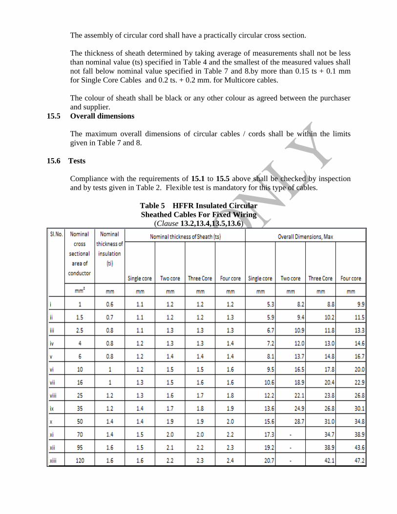
Table 5 HFFR Insulated Circular
Sheathed Cables For Fixed Wiring
(Clause 13.2,13.4,13.5,13.6)
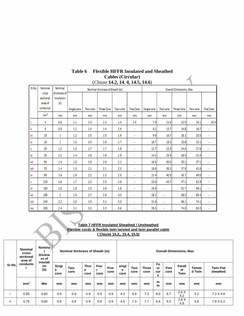
Table 6 Flexible HFFR Insulated and Sheathed
Cables (Circular)
(Clause 14.2, 14. 4, 14.5, 14.6)
Table 7 HFFR Insulated Sheathed / Unsheathed
Flexible cords & flexible twin twisted and twin parallel cable
( Clause 15.2,, 15.4, 15.5)
Sr.No.
Nominal cross
sectional area of
conductor
Nominal
thickness of
insulation (ti)
Nominal thickness of Sheath (ts) Overall Dimensions, Max
Single core
Two core
Three core
Four core
Five core
single
core
Two core
Three core
Four
core
Five core
Parallel
Twin
Twisted Twin
Twin Flat sheathed
mm2 Mm mm mm mm mm mm mm mm mm mm
mm mm mm mm
i 0.50 0.60 0.9 0.9 0.9 0.9 0.9 4.3 6.9 7.3 8.0 8.7 2.6 X 5.2
5.2 7.2 X 4.9
ii 0.75 0.60 0.9 0.9 0.9 0.9 0.9 4.5 7.3 7.7 8.4 9.2 2.8 X 5.6
5.6 7.8 X 5.2

iii 1.00 0.60 0.9 0.9 0.9 0.9 1.0 4.7 7.6 8.1 8.8 9.6 3.0 X 6.0
6.0 8.0 X 5.4
iv 1.50 0.60 0.9 0.9 0.9 1.0 1.0 5.4 8.9 9.4 10.4
11.4 3.3 X 6.6
6.6 8.6 X 5.6
v 2.50 0.70 1.0 1.0 1.0 1.0 1.0 6.2 10.3 10.9 12.0
13.2 4.0 X 8.0
8.0 10.5 X 6.6
vi 4.00 0.80 - - - - - - - - - - 4.8 X 9.6
9.6 12.0 X 7.4
Table 8 Flexible Halogen Free Flame Retardant (HFFR)
Insulated and Sheathed Cables (Circular)
(Clause 15.2, 15.4, 15.5)
Nominal thickness of insulation (ti)
mm
Nominal thickness of sheath (ts)
mm
Overall dimension
max. mm
Nominal thickness of insulation (ti)
mm
Nominal thickness of sheath (ts)
mm
Overall dimension
max. mm
Nominal thickness of insulation (ti)
mm
Nominal thickness of sheath (ts)
mm
Overall dimension
max. mm
Nominal thickness of insulation (ti)
mm
Nominal thickness of sheath (ts)
mm
Overall dimension
max. mm
Nominal thickness of insulation (ti)
mm
Nominal thickness of sheath (ts)
mm
Overall dimension
max. mm
(1) (2) (3) (4) (5) (6) (7) (8) (9) (10) (11) (12) (13) (14) (15) (16) (17)
i 6 0.6 0.9 9.5 0.6 1 10.0 0.6 1 10.5 0.6 1 12.6 0.7 1.1 14.7 ii 7 0.6 0.9 9.5 0.6 1 10.0 0.6 1 10.5 0.6 1 12.6 0.7 1.1 14.7 iii 8 0.6 1 11.1 0.6 1 11.8 0.6 1 12.4 0.6 1.1 14.9 0.7 1.2 17.5 iv 9 0.6 1 11.8 0.6 1.1 12.4 0.6 1.1 13.1 0.6 1.1 15.8 0.7 1.3 18.5 v 10 0.6 1 12 0.6 1.1 12.7 0.6 1.1 13.4 0.6 1.1 16.2 0.7 1.3 18.9 vi 11 0.6 1 12 0.6 1.1 12.7 0.6 1.1 13.4 0.6 1.1 16.2 0.7 1.3 18.9 vii 12 0.6 1 12.4 0.6 1.1 13.1 0.6 1.1 13.9 0.6 1.1 16.7 0.7 1.3 19.6 viii 13 0.6 1 13.1 0.6 1.1 13.8 0.6 1.1 14.6 0.6 1.2 17.6 0.7 1.3 20.7 ix 14 0.6 1.1 13.1 0.6 1.1 13.8 0.6 1.1 14.6 0.6 1.2 17.6 0.7 1.3 20.7 x 15 0.6 1.1 13.5 0.6 1.2 14.3 0.6 1.2 15.1 0.6 1.2 18.3 0.7 1.4 21.5 xi 16 0.6 1.1 13.8 0.6 1.2 14.6 0.6 1.2 15.4 0.6 1.2 18.6 0.7 1.4 21.9 xii 17 0.6 1.1 14.6 0.6 1.2 15.4 0.6 1.2 16.3 0.6 1.3 19.7 0.7 1.4 23.2 xiii 18 0.6 1.1 14.6 0.6 1.2 15.4 0.6 1.2 16.3 0.6 1.3 19.7 0.7 1.4 23.5 xiv 19 0.6 1.1 14.6 0.6 1.2 15.4 0.6 1.3 16.3 0.6 1.3 19.7 0.7 1.4 24 xv 20 0.6 1.2 15.4 0.6 1.3 16.3 0.6 1.4 17.3 0.6 1.4 20.9 0.7 1.5 24.6 xvi 21 0.6 1.2 15.4 0.6 1.3 16.3 0.6 1.4 17.3 0.6 1.4 20.9 0.7 1.5 25.2 xvii 22 0.6 1.2 16.3 0.6 1.3 17.3 0.6 1.4 18.2 0.6 1.4 22.1 0.7 1.5 26 xviii 23 0.6 1.2 16.3 0.6 1.3 17.3 0.6 1.4 18.2 0.6 1.4 22.1 0.7 1.5 26.5 xix 24 0.6 1.2 17.1 0.6 1.3 18.2 0.6 1.4 19.2 0.6 1.4 23.2 0.7 1.5 27.4 xx 25 0.6 1.2 17.1 0.6 1.3 19.0 0.6 1.4 19.2 0.6 1.4 23.2 0.8 1.5 28.1
2.5 Sq.mm No. of Cores 0.50 Sq.mm 0.75 Sq.mm 1.0 Sq.mm 1.5 Sq.mm Sl.No.

Table No. 9 Recommended Lay-up of cores
(Clause 15.3)
No. of cores Lay-up
2 2
3 3
4 4
5 5
6 D-6
7 1- 6
8 1-7
9 1-8
10 2-8
11 3-8
12 3-9
13 3-10
14 4-10
15 5-10
16 5-11
17 5-12
18 D-6-12
19 1-6-12
20 1-7-12
21 1-7-13
22 2-7-13
23 2-8-13
24 2-8-14
25 2-8-15
NOTE D – Dummy core with HFFR property

Annex 1
(Clause 4.2.1)
Halogen free Flame Retardant Insulated cables
Sl.No
(1)
Test
(2)
Unit
(3)
Test
Method
(4)
Type of Insulation
(5)
HFI-TP70 HFI-XL70 HFI-XL90 A General
1 Rated Temperature 70°C 70°C 90°C
2 Insulation resistance constant at rated temp.
MΏ.km IS 10810-
43
Min.0.037 Min.0.037 Min.0.037
Temperature °C 70 ± 2 70 ± 2 90 ± 2
Test Duration Hr. 1 1 1
3
Properties before ageing
3.1
Values to be obtained for the tensile strength:
- min
N/mm2
IS 10810-
7
7.5 10 10
Values to be obtained for the elongation at break:
- min
% 150 125 125
3.2
Properties after ageing in air oven
IS 10810- 11
Ageing conditions: - temperature
- duration of treatment
oC Hrs
80 + 2 7 x 24
100 + 2 7X24
135 ± 2 7X24
Value to be obtained for the tensile strength:
- min. - variation, max
N/mm2
%
-
+ 20
-
+ 30
-
+ 30
Values to be obtained for the elongation at break:
- min - variation, max.
N/mm2
%
- + 20
- + 30
- + 25
4 Hot Deformation Test
IS 10810- 15
Temperature o C
80±2
-
-
Period of test Hr. 4 - -
Result % Max. 50 - -
5 Hot set test
IS 10810- 30
Temperature o C
- 200±3 200±3
Period under load Minutes - 15 15
Mechanical stress N/cm² - 20 20
Elongation under load, max % - 175 175
Permanent Elongation, max
% - 15 15
6 Cold Bend Test
IS 10810-
20
Temperature o C
-15 ± 2 -15 ± 2 -15 ± 2
Period of test Hr. 3 3 3
Result No Cracks No Cracks No Cracks
7 Cold Impact Test
Temperature
o C
IS 10810- 21
-15 ± 2 -15 ± 2 -15 ± 2
Period of test Hrs. 3 3 3
Result No Cracks No Cracks No Cracks
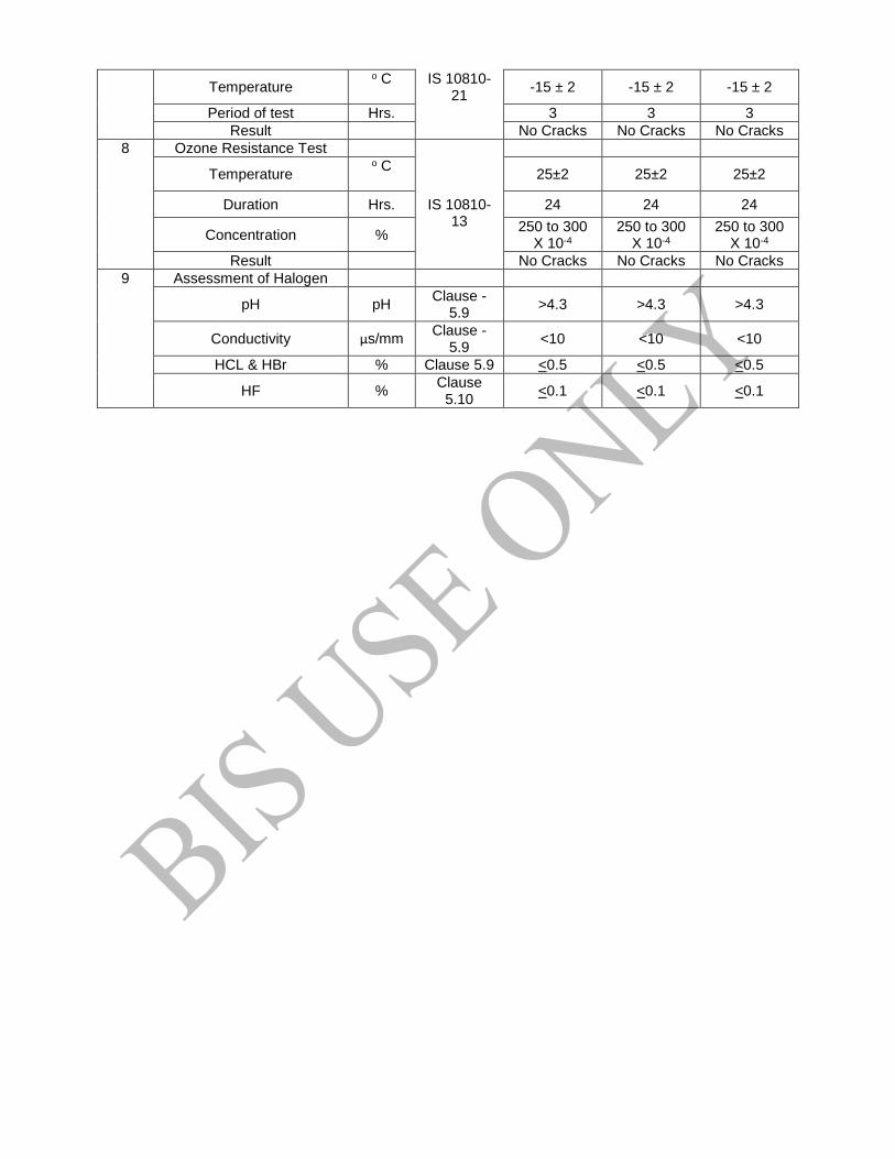
8 Ozone Resistance Test
IS 10810-
13
Temperature o C
25±2 25±2 25±2
Duration Hrs. 24 24 24
Concentration % 250 to 300
X 10-4 250 to 300
X 10-4 250 to 300
X 10-4
Result No Cracks No Cracks No Cracks
9 Assessment of Halogen
pH pH Clause -
5.9 >4.3 >4.3 >4.3
Conductivity µs/mm Clause -
5.9 <10 <10 <10
HCL & HBr % Clause 5.9 <0.5 <0.5 <0.5
HF % Clause
5.10 <0.1 <0.1 <0.1

Annex 2 (Clause 4.5.1)
Halogen free Flame Retardant Sheathed cables
Sl.No
(1)
Test
(2)
Unit
(3)
Test
Method
(4)
Type of sheathing
(5)
HFS-
TP70
HFS-TP
90
HFS-
XL70
HFS-XL90
A General
1
Rated Temperature 70°C 90°C 70°C 90°C
2
Properties before
ageing
IS 10810- 7
2.1
Values to be obtained for the tensile
strength: - min
N/mm2
10
10
10
10
Values to be obtained for the elongation at
break: - min
%
100
100
125
100
2.2
Properties after ageing in air oven
IS 10810- 11
Ageing conditions: - temperature
- duration of treatment
oC
Hrs.
80 + 2 7 x 24
100± 2 7 x 24
100± 2 7X24
100± 2
7X24
Value to be obtained for the tensile
strength: - min
- variation, max
N/mm2 %
10 + 25
10 + 40
7
+30
10 + 40
Values to be obtained for the elongation at
break: - min
- variation, max.
% %
100 + 25
100 + 40
125 + 30
100 + 40
3 Hot Deformation Test IS 10810- 15
Temperature o C
80 ± 2 90 ± 2 80±2 80±2
Period of test Hr. 4 4 4 4
Result % Max 50% Max 50% Max 50% Max 50%
4 Hot set test
Temperature o C IS 10810- 30
- - 200±3 200±3
Period under load Minutes
- - - 15 15

Mechanical stress N/cm² - - 20 20
Elongation under load, max.
% - - 175 175
Permanent Elongation, max.
%, - - 15 15
5 Cold Bend Test IS 10810- 20
Temperature o C
-15 ± 2 -15 ± 2 -15±2 -15±2
Period of test Hr. 3 3 3 3
Result No Cracks No Cracks No Cracks No Cracks
6 Cold Impact Test IS 10810- 21
Temperature oC
-15 ± 2 -15 ± 2 -15±2 -15±2
Period of test Hrs. 3 3 3 3
Result No Cracks No Cracks No Cracks No Cracks
7 Assessment of Halogen
HCL & HBR % Clause -5.9
<0.5 <0.5 <0.5 <0.5
pH and conductivity µS/mm ANNEX 6 pH≥ 4.3 and conductivity ≤ 10 µS/mm
8 Water immersion test Cl.
5.16
Temperature o C
70 70 70 70
Period of test Hr. 7x24 7x24 7x24 7x24
Variation in TS % ± 30 ± 30 ±30 ±30
Variation in Elong. % % ± 30 ± 30 ±30 ±30
9 Ozone Resistance Test
IS 10810-
13
Temperature o C
25±2
25±2
25±2
25±2
Duration Hr. 24 24 24 24
Concentration % 250 to 300 X 10-4
250 to 300 X 10-4
250 to 300 X 10-4
250 to 300 X 10-4
Result No Cracks No Cracks No Cracks No Cracks
Annex 3
(Clause 8)
SAMPLING OF CABLES
B-1 LOT

B-1.1 In any consignment the cables of the same size
and type manufactured under essentially similar
conditions of production shall be grouped together to
constitute a lot.
B-2.2.1 In order to ensure the randomness of selection,
procedure given in IS 4905:1948 may be followed
B-2 SCALE OF SAMPLING B-3 NUMBER OF TESTS AND CRITERION FOR
CONFORMITY
B-2.1 Samples shall be taken and tested from each lot for
ascertaining the conformity of the lot to the requirements
of the specification.
B-3.1 From each of the drum/coils/reels selected
according to col 1 and 2 of the above table, suitable
lengths of test samples shall be taken. These test samples
shall be subjected to each of the acceptance tests. A test
sample is called defective if it fails in any one of the
acceptance tests. If the number of defectives is less than
or equal to the corresponding permissible number given
in col 3 of the above table, the lot shall be declared as
conforming to the requirements of the acceptance tests;
otherwise not.
B-2-2 The number of samples to be selected shall
depend on col 1 and 2 of the following table. These
samples shall be taken at random.
Scale of sampling
Number of drums/coils/reels in the lot
Number of drums/coils/reels to be taken as samples
Permissible number of defectives
Up to 50 3 0
51 to 100 5 0
101 to 300 8 0
301 and above 13 2
Annex 4
(Clause 5.7)
ASSESSMENT OF HALOGENS
Requirements for HFFR cables
The insulation and sheath shall meet the following type test requirements as shown in
following table

TABLE 1
(Clause 5.8)
Sl.no. Test method measure Requirements 1 clause pH and conductivity pH≥ 4.3 and
conductivity ≤ 10
µS/mm
2 IS 10810-59 Chlorine and Bromine content expressed
as content of HCL
≤ 0.5%
3a Annexure 4 Presence of fluorine If negative stop test
3b Annexure 4 If positive test as per 3b
Sample Test ― The material shall be tested as per given sequence as per the table given below: TABLE 2
(Clause 5.7, 5.8)
Sl.no. Test method measure Requirements Outcome
Step 0 Annexure 5 Halogen : Fluorine, Chlorine and
Bromine
Negative value If negative stop
test – material
accepted. If
positive go to
step 1
Step 1 Annexure – 6
(IEC 754 – 2)
pH pH < 4.3 Reject the
material
pH > 4.3 Evaluate
Conductivity
Conductivity < 2.5µ S/mm Accept no
further testing
required
> 10 µS/mm Reject material
> 2.5 <10 Chlorine
bromine
determination
as per
Annexure 6
2 Annexure 5
Chlorine and Bromine content
expressed as content of HCL
>0.5% Reject material
< 0.5% Test as per
annexure 5
Fluorine content >0.1 % Reject material
< 0.1% Accept material
ANNEX 5
(Clause 5.7) DETERMINATION OF HALOGENS – ELEMENTAL TEST
Warning – Owing to its potentially hazardous nature the fusion operation should be carried out in
a fume cabinet, using safety screen
0. EQUIPMENT
a) Bunsen Burner
b) Glass Test tubes of approximately 50mm x 10mm
c) Test tube Holder
d) Evaporating basin / Mortar
e) Wire Gauge
f) Funnel and
g) Filter paper
1. MATERIALS
a) Sample
b) Sodium metal
c) Nitric acid ( 5 percent)
d) Aqueous silver nitrate (5 percent)
e) Freshly prepared Zirconium-alizarin red S Reagent
f) Glacial Acetic Acid and
g) pH papers
2. PROCEDURE
3.1 Sodium fusion
Place 200 to 250 mg of the sample into the bottom of a small soda glass test tube. Add
10 ml of de-ionized water to the evaporating basis and place this in the fume cub board
behind the safety screen. Whilst holding the test tube firmly with the test tube holder at
an angle of 45 to 60° to the vertical, introduce a piece of freshly cut, clean sodium in size
of a small pie ( 200 to 250 mg) into the mouth of the test tube without allowing it to come
into contact with the sample directly. With the safety screen in place, heat the sodium
gently until it melts and runs down on to the sample leading to vigorous reaction when
the molten sodium reaches the sample in case of presence of halogen. Heat the test tube
gently for about a minute, then more strongly until the lower 20 mm of the test tube
glows red hot. Plunge the red hot tube into the water in the evaporating basin,
immediately placing the gauze on the top, to prevent the loss of material when tube
shatters on contact with water. Allow any unreacted sodium to react before grinding up
the solution and glass. Filter and separate the filtrate into two equal portions.
3.2 Determination of Presence of Chlorine and bromine
To the first portion of the filtrate, add sufficient nitric acid to make the solution acidic.
Boil this total volume till reduced by half, to remove any HCN or H2S, if present, which
would interfere with the test. Add 1 ml of Silver nitrate solution a white or yellowish
precipitate indicates the presence of halogen ( Cl, Br), in the original sample.( if the
liquour is decanted and the precipitate is white and readily soluble in dilute ammonia then
chloride is present).
3.3 Determination of Presence of Fluorine
To the second portion of the filtrate, acidify with glacial acetic acid. Boil this solution
until its total volume is reduced to half.

Add two to three drops of freshly prepared zirconium lake reagent ( Equal volume of )
a) Alizarin in solution : Prepared by mixing 0.05 gm Alizarin in Red –S in 50ml distilled
water
b) Zirconium solution: 0.05gm Zirconium nitrate in 10 ml concentrated HCL diluted
with 50 ml of distilled water.
Heat at 40°C for one hour. The presence of fluoride is indicated by the red / pink
colouration being bleached to yellow.
ANNEX 6
(Clause 5.9)
DETERMINATION OF DEGREE OF ACIDITY OF COMBUSTION GASES FOR
MATERIAL BY MEASURING PH AND CONDUCTIVITY
The quality of water used for test shall be as given below:
pH 6.5±1
Conductivity < 0.5µS/mm
1000± 5mg of Representative sample of material to be tested conditioned for at least 16 hrs at a
temperature of ( 23 ±2 °C and at a relative humidity of (50±5 percent) shall be put into the
bottom of combustion boat and evenly distributed. The air flow shall be maintained at
(0.0157D²) l /hr±10 percent and maintained constantly throughout the test. The boat with sample

inserted into the centre of the tube furnace and the timer started. The combustion boat shall be
placed in such a way that the distance between the boat and the exit end of the effective heating
zone is > 300mm and temperature measured at the position of boat shall not be less than 935°C
and the temperature at position of 300 mm from the boat at the direction of the boat shall not be
less than 900°C. The period of the combustion and air flow shall be continued for 30 minutes in
the furnace.
After the test the contents of the both the bottles shall be made up to 1000 ml using water of
quality stated above. pH test is done at room temperature . The pH value shall be read using the
pH meter with automatic temperature compensation facility. Conductivity shall be measured as
per the procedure given by the supplier.
This test shall be performed on each non-metallic material of the cable. The cable declared
passed provided it meets the requirement specified in table one of annex 4.