bulletin no. iams-d drawing no. lp0475 tel +1 (717) 767 ... product manual - (for...the iams...
TRANSCRIPT

GENERAL DESCRIPTIONThe IAMS3535 Smart Analog to MODBUS Conditioner with Alarms
module accepts a wide range of DC analog process signals. There are eighteendifferent DC analog input ranges which determine the input span and type. Theinput accepts a maximum of 110 VDC and 110 mA DC.
The IAMS converts an analog input signal into a register format that can beread using ASCII or RTU MODBUS protocol. With the features of gain andoffset, the input signal can be scaled to meet process requirements. Additionally,two setpoint values can be entered for dual relay process monitoring alarms.
The IAMS is programmed with Windows® based SFIMS software. Thesoftware allows configuration, calibration, and storage of IAMS program files.Additionally, all setup parameters can be interrogated and modified throughMODBUS register and coil commands.
The RS485 port allows the IAMS to be multidropped, with Baud rates up to38400. The CBPRO007 programming cable converts the RS232 port of a PC toRS485, and is terminated with an RJ-11 connector. The bidirectional capabilityof the CBPRO007 allows it to be used as a permanent interface cable as well asa programming cable.
The IAMS’s two Form A relay alarms can be configured independently forabsolute high or low acting with balanced or unbalanced hysteresis. Alarm 2 canalso be configured for deviation and band alarms. In these modes, Setpoint 2tracks Setpoint 1. Adjustable alarm trip delays can be used for delaying outputresponse. The alarms can be programmed for Automatic or Latching. Latchedalarms must be reset via serial command. A standby feature supresses the alarmduring power-up until the process stabilizes outside the alarm region. Standbyeliminates power-up tripping for low acting alarms. The output relays can alsobe manually controlled via register commands.
The module’s high density packaging and DIN rail mounting saves time andpanel space. The module is equipped with a universal mounting foot forattachment to standard DIN rails, including top hat (T) profile or G profile rail.
SAFETY SUMMARYAll safety related regulations, local codes and instructions that appear in the
manual or on equipment must be observed to ensure personal safety and toprevent damage to either the instrument or equipment connected to it. Ifequipment is used in a manner not specified by the manufacturer, the protectionprovided by the equipment may be impaired.
ORDERING INFORMATION
SPECIFICATIONS1. POWER: 18 to 36 VDC, 3.0 W max. or 24 VAC, ± 10%, 50/60 Hz, 4 VA max.2. INPUT DC RANGES:
0-20 mV, 0-50 mV, 0-100 mV, 0-200 mV, 0-500 mV, 0-1V, 0-2 V, 0-5 V, 0-10 V, 0-20 V, 0-50 V, 0-100 V, 0-2 mA, 0-5 mA, 0-10 mA, 0-20 mA, 0-50 mA, 0-100 mA
3. MAX. INPUT SIGNAL: Current Input: 110 mA DCVoltage Inputs: Terminal 7: 1 VDC +10%
Terminal 8: 10 VDC +10%Terminal 9: 100 VDC +10%
4. INPUT RESISTANCE: Current: 10 OhmsVoltage: greater than 100 K
5. INPUT PROTECTION: Surge suppressor diodeCurrent Terminal: Protected to 110 mA DC max., 1.1 VDC.100 V Terminal: Protected to 110 VDC.1 V & 10 V Terminal: Protected to 100 VDC for one minute.
6. INPUT COMMON MODE REJECTION: 50/60 Hz, 110 dB min.7. ISOLATION LEVEL: 1.5 kV @ 50/60 Hz, 1 min. between input, RS485
and power supply. 2300 Vrms, 1 min. to relay contacts.
1
ANALOG TO MODBUS CONVERSION
18 DIFFERENT DC ANALOG INPUT RANGES
PROCESSOR BASED SCALING
PC CONFIGURATION SOFTWARE
DUAL SETPOINT RELAY ALARMS
FOUR WAY SIGNAL ISOLATION
MODEL IAMS - INTELLIGENT ANALOG TO MODBUS CONDITIONER W/ ALARMS
IAMSDESCRIPTION
Smart Analog to Modbus Conditioner w/AlarmsPART NUMBER
IAMS3535
CBPROSFIMS
Programming Interface CablePC Configuration Software for Windows
CBPRO007SFIMS
-
CBJ
RJ11 to Terminal Adapter
Cable RJ11 to Unterminated 7 foot length
DRRJ11T6
CBJ11A07Cable RJ11 to RJ11 6 inch jumper CBJ11BD5
DIMENSIONS In inches (mm)
CAUTION: Risk of DangerRead complete instructions prior to
installationand operation of the unit.
CAUTION: Risk of electric shock.
Bulletin No. IAMS-D
Drawing No. LP0475
Released 2/07
Tel +1 (717) 767-6511
Fax +1 (717) 764-0839
www.redlion.net
UL Recognized Component,File # E179259
MODEL NO.

2
8. SERIAL COMMUNICATIONS: Type: RS485, MODBUS RTU and ASCII modesBaud: 300, 600, 1200, 2400, 4800, 9600, 19.2K, and 38.4KFormat: 7/8 bit, odd, even and no parityTransmit Delay: Programmable. (See Transmit Delay explanation in Step 6)Transmit Enable (TXEN): (primarily for 20 mA loop converter)VOH = 10 VDC max. VOL = 0.5 VDC @ 5 mA max. current limit
9. A/D CONVERTER: 16 bit resolution10. ACCURACY (including linearity): 0.1% of span11. RESOLUTION: 0.002% of span12. GAIN / OFFSET: Programmable13. RELAY OUTPUTS:
Type: 2 Form A N.O. contactsRating: 5A @ 30 VDC or 250 VAC max. (resistive)
1/10 HP @ 120 VAC (inductive)Response Time: 155 msec. max. to close including step response, 153 msec.max. to open.
14. OUTPUT ON DELAY TIME: Programmable from 0 to 32000 sec, ±0.01% - 1 sec. max.
15. MEMORY: Nonvolatile E2PROM retains all programmable parameters.16. ENVIRONMENTAL CONDITIONS:
Operating Temperature Range: -20 to +65 °CStorage Temperature Range: -40 to +85 °COperating and Storage Humidity: 85% max. relative humidity (non-condensing) from -20 to +65 °CTemperature Coefficient: +0.01%/ °C (100 PPM °C) max.Altitude: Up to 2000 meters
17. CERTIFICATIONS AND COMPLIANCE: SAFETY
UL Recognized Component, File # E179259, UL3101-1, CSA 22.2 No. 1010-1Recognized to U.S. and Canadian requirements under the ComponentRecognition Program of Underwriters Laboratories, Inc.
IECEE CB Scheme Test Certificate # US/5141A/UL, CB Scheme Test Report # 01ME11540-0702001
Issued by Underwriters Laboratories, Inc.IEC 61010-1, EN 61010-1: Safety requirements for electrical equipment
for measurement, control, and laboratory use, Part 1.ELECTROMAGNETIC COMPATIBILITY
Notes:1. This device was designed for installation in an enclosure. To avoid
electrostatic discharge to the module in environments with static levelsabove 6 KV, precautions should be taken when the device is mountedoutside an enclosure. When working in an enclosure (ex. makingconnections, etc.), typical anti-static precautions should be observedbefore touching the module.
Refer to the EMC Installation Guidelines section of this bulletin foradditional information.
18. CONSTRUCTION: Case body is black high impact plastic. InstallationCategory II, Pollution Degree 2.
19. CONNECTIONS: 14 AWG max.20. MOUNTING: Universal mounting foot for attachment to standard DIN
style mounting rails, including top hat (T) profile rail according to EN50022- 35 x 7.5 and - 35 x 15, and G profile rail according to EN50035 - G32.
21. WEIGHT: 4.5 oz. (127.57 g)
MODULE ISOLATION The IAMS features “4-way” signal isolation. The 4-way isolation is a
combination of optical, transformer and relay barriers, providing common modevoltage (CMV) isolation to 1.5 KV for 1 minute between input, RS485, andpower supply. Isolation between relay contacts and all other inputs is 2300 Vrmsfor 1 minute.
LED FUNCTIONALITY
Power mains class AEnclosure class AEN 55011RF interference
Emissions to EN 55011
Level 3; 10 V/mENV 50204Simulation of cordless telephone150 KHz - 80 MHzLevel 3; 10 V/rms EN 61000-4-6RF conducted interferenceLevel 3; 2 KV power Level 4; 2 KV I/O EN 61000-4-4Fast transients (burst)80 MHz - 1 GHzLevel 3; 10 V/MEN 61000-4-3Electromagnetic RF fieldsLevel 3; 8 KV air1
Level 2; 4 KV contact EN 61000-4-2Electrostatic discharge
200 Hz, 50% duty cycle
Immunity to EN 50082-2
900 MHz ± 5 MHz
CONDITION GREEN LED 2 RED LEDS
Power Applied On ———Communication Received Flashing ———Respective Alarm ——— OnChecksum error Flashing FlashingCalibration Off On
BLOCK DIAGRAM

3
WIRING CONNECTIONSAll conductors should meet voltage and current ratings for each terminal.
Also, cabling should conform to appropriate standards of good installation,local codes and regulations. When wiring the module, use the numbers on thelabel to identify the position number with the proper function. Strip the wire,leaving approximately 1/4" (6 mm) of bare wire exposed. Insert the wire intothe terminal, and tighten the screw until the wire is clamped tightly. (Pull wireto verify tightness.) Each terminal can accept up to one #14 AWG (2.55 mm),two #18 AWG (1.02 mm), or four #20 AWG (0.61 mm) wires.
MODULE POWER CONNECTIONSModule power is connected to terminals 1 and 2. For best results, the power
should be relatively “clean” and within the specified limits. Drawing powerfrom heavily loaded circuits or from circuits that also power loads that cycle onand off should be avoided. It is recommended that power supplied to the modulebe protected by a fuse or circuit breaker.
INPUT CONNECTIONSCurrent Input
Wiring for a current input isconnected to terminals 10 (+) and 12 (-).
Terminal 10 (+): 100 mA
Voltage InputWiring for a voltage input is
connected to terminal 12 (-) and one ofthe voltage terminals listed below.
Terminal 7 (+): 1 VDC max.Terminal 8 (+): 10 VDC max.Terminal 9 (+): 100 VDC max.
RELAY OUTPUT CONNECTIONSThere are two Form A output relays. The wiring for Relay 1 is connected
between terminals 5 and 6. The wiring for Relay 2 is connected betweenterminals 3 and 4.
To prolong contact life and suppress electrical noise interference due to theswitching of inductive loads, it is good installation practice to install a snubberacross the contactor. Follow the manufacturer’s instructions for installation.
Note: Snubber leakage current can cause some high impedance loads to beheld ON.
DEFAULT SERIAL SETTING CONNECTIONIf the IAMS settings are unknown, or forgotten, they can be reset to the
factory defaults by connecting the Serial Default terminal 11 to Input Comm.terminal 12 with a jumper, and then cycling power.
DEFAULTS:
RS485 SERIAL CONNECTIONSThere are two RJ-11 connectors located on the bottom for paralleling
communications. For single device communications, either connector can beused. When used in conjunction with Red Lion Control Paradigm HMIproducts, reverse A+ and B- wiring.
RJ11 IAMS1 Not used
2 B-
3 A+
4 COMM
5 TXEN
6
2 3 4 5
Not used IAMS CONNECTOR
STEP 1 WIRING THE MODULE
Protocol: RTUAddress: 247Baud Rate: 9600
Data Bits:Parity:
8none
Although this unit is designed with a high degree of immunity to Electro-Magnetic Interference (EMI), proper installation and wiring methods must befollowed to ensure compatibility in each application. The type of the electricalnoise, source or coupling method into the unit may be different for variousinstallations. Cable length, routing, and shield termination are very importantand can mean the difference between a successful or troublesome installation.
Listed below are some EMC guidelines for successful installation in anindustrial environment.1. Use shielded (screened) cables for all Signal and Control inputs. The shield
(screen) pigtail connection should be made as short as possible. Theconnection point for the shield depends somewhat upon the application.Listed below are the recommended methods of connecting the shield, in orderof their effectiveness.a. Connect the shield only at the rail where the unit is mounted to earth
ground (protective earth).b. Connect the shield to earth ground at both ends of the cable, usually when
the noise source frequency is above 1 MHz.c. Connect the shield to common of the unit and leave the other end of the
shield unconnected and insulated from earth ground.2. Never run Signal or Control cables in the same conduit or raceway with AC
power lines, conductors feeding motors, solenoids, SCR controls, andheaters, etc. The cables should be run in metal conduit that is properlygrounded. This is especially useful in applications where cable runs are longand portable two-way radios are used in close proximity or if the installationis near a commercial radio transmitter.
3. Signal or Control cables within an enclosure should be routed as faraway as possible from contactors, control relays, transformers, and othernoisy components.
4. In extremely high EMI environments, the use of external EMIsuppression devices, such as ferrite suppression cores, is effective.Install them on Signal and Control cables as close to the unit as possible.Loop the cable through the core several times or use multiple cores oneach cable for additional protection. Install line filters on the powerinput cable to the unit to suppress power line interference. Install themnear the power entry point of the enclosure. The following EMIsuppression devices (or equivalent) are recommended:Ferrite Suppression Cores for signal and control cables:
Fair-Rite # 0443167251 (RLC # FCOR0000)TDK # ZCAT3035-1330ASteward # 28B2029-0A0Line Filters for input power cables:Schaffner # FN610-1/07 (RLC # LFIL0000)Schaffner # FN670-1.8/07Corcom # 1 VR3
Note: Reference manufacturer’s instructions when installing a line filter.5. Long cable runs are more susceptible to EMI pickup than short cable runs.
Therefore, keep cable runs as short as possible.
EMC INSTALLATION GUIDELINES

4
STEP 4 PROGRAMMING THE INPUTThe IAMS receives an analog input, converts it to a raw digital value, and stores this number in the ADC Value (register 40001). This number is scaled
into engineering units using the Gain Value (register 40010) and Offset Value (register 40011). The result of this scaling is stored as the Process Value(register 40002). It is also stored in the IEEE 754 Standard 32-bit floating decimal format (register 40003 and 40004). The non-scaled ADC, the scaledProcess value, or the Floating point value may be accessed for the purpose of monitoring the input level.
INPUTSIGNAL
ADC READING
Register 40001
INTERNALMATH
GAIN/OFFSET PROCESSVALUE
IEEE STANDARD 754FLOATING DECIMAL POINT
LO Order ByteHI Order Byte
Register 40003Register 40004
Register 40002Register40010/40011
Input Range: Select the desired input range from the pull down menu.
Gain & Offset: The Gain & Offset values are used to scale the input signal intoengineering units. The result is stored in the Process Value register. To determine theGain and Offset for your application, use the Scaling Wizard button.
STEP 3 PROGRAMMING - Getting Started
Run RLCPro by double-clicking the icon, or use the start menu.
Use the FILE pull-down menuto select a NEW file.
You will be prompted toselect the proper device,
and then the model.
STEP 2 INSTALLING SFIMS (Software for Intelligent Modules)Insert the SFIMS diskette into the A: or B: drive. Then Run A:\SETUP
(or B:\SETUP) to install RLCPro onto the hard drive. An icon labeledRLCPro will be created under the group RLCPro.
5
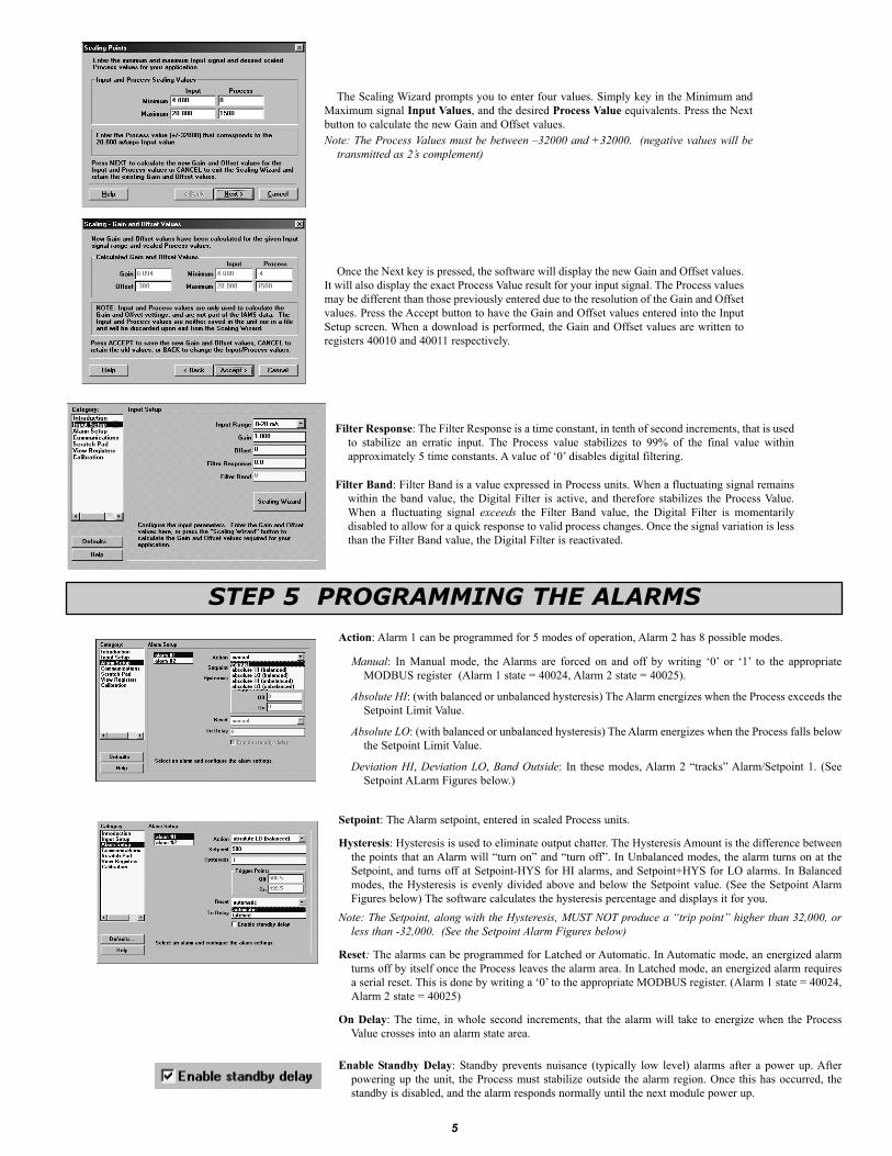
Filter Response: The Filter Response is a time constant, in tenth of second increments, that is usedto stabilize an erratic input. The Process value stabilizes to 99% of the final value withinapproximately 5 time constants. A value of ‘0’ disables digital filtering.
Filter Band: Filter Band is a value expressed in Process units. When a fluctuating signal remainswithin the band value, the Digital Filter is active, and therefore stabilizes the Process Value.When a fluctuating signal exceeds the Filter Band value, the Digital Filter is momentarilydisabled to allow for a quick response to valid process changes. Once the signal variation is lessthan the Filter Band value, the Digital Filter is reactivated.
The Scaling Wizard prompts you to enter four values. Simply key in the Minimum andMaximum signal Input Values, and the desired Process Value equivalents. Press the Nextbutton to calculate the new Gain and Offset values.Note: The Process Values must be between –32000 and +32000. (negative values will be
transmitted as 2’s complement)
Once the Next key is pressed, the software will display the new Gain and Offset values.It will also display the exact Process Value result for your input signal. The Process valuesmay be different than those previously entered due to the resolution of the Gain and Offsetvalues. Press the Accept button to have the Gain and Offset values entered into the InputSetup screen. When a download is performed, the Gain and Offset values are written toregisters 40010 and 40011 respectively.
STEP 5 PROGRAMMING THE ALARMS
Action: Alarm 1 can be programmed for 5 modes of operation, Alarm 2 has 8 possible modes.
Manual: In Manual mode, the Alarms are forced on and off by writing ‘0’ or ‘1’ to the appropriateMODBUS register (Alarm 1 state = 40024, Alarm 2 state = 40025).
Absolute HI: (with balanced or unbalanced hysteresis) The Alarm energizes when the Process exceeds theSetpoint Limit Value.
Absolute LO: (with balanced or unbalanced hysteresis) The Alarm energizes when the Process falls belowthe Setpoint Limit Value.
Deviation HI, Deviation LO, Band Outside: In these modes, Alarm 2 “tracks” Alarm/Setpoint 1. (SeeSetpoint ALarm Figures below.)
Setpoint: The Alarm setpoint, entered in scaled Process units.
Hysteresis: Hysteresis is used to eliminate output chatter. The Hysteresis Amount is the difference betweenthe points that an Alarm will “turn on” and “turn off”. In Unbalanced modes, the alarm turns on at theSetpoint, and turns off at Setpoint-HYS for HI alarms, and Setpoint+HYS for LO alarms. In Balancedmodes, the Hysteresis is evenly divided above and below the Setpoint value. (See the Setpoint AlarmFigures below) The software calculates the hysteresis percentage and displays it for you.
Note: The Setpoint, along with the Hysteresis, MUST NOT produce a “trip point” higher than 32,000, orless than -32,000. (See the Setpoint Alarm Figures below)
Reset: The alarms can be programmed for Latched or Automatic. In Automatic mode, an energized alarmturns off by itself once the Process leaves the alarm area. In Latched mode, an energized alarm requiresa serial reset. This is done by writing a ‘0’ to the appropriate MODBUS register. (Alarm 1 state = 40024,Alarm 2 state = 40025)
On Delay: The time, in whole second increments, that the alarm will take to energize when the ProcessValue crosses into an alarm state area.
Enable Standby Delay: Standby prevents nuisance (typically low level) alarms after a power up. Afterpowering up the unit, the Process must stabilize outside the alarm region. Once this has occurred, thestandby is disabled, and the alarm responds normally until the next module power up.

6
STEP 6 PROGRAMMING THE IAMS COMMS PORT
The IAMS’ serial port must match the device being used to communicate to it.MODBUS Protocol: RTU or ASCIIUnit Address: 1-247Baud Rate: 300, 600, 1200, 2400, 4800, 9600, 19200, or 38400Data Bits: 7 or 8Parity: odd, even, or noneTransmit Delay: Programmable from 1-255 milliseconds. The Transmit Delay is the time the IAMS
will wait to respond to a serial command, UNLESS the values in the table below are larger.
Note: If the Unit Address, Protocol, Baud rate, etc. arechanged, and then a download is performed, the unitwill now respond to the new settings. Any furtherattempts to communicate to the module must targetthe new address, with the new settings.The IAMS’serial settings must match the device thatit is communicating with. If you do not know orcannot recall the IAMS settings, they can be resetback to factory defaults. Simply jumper the SerialDefault terminal to Common, and cycle power. Theserial settings will default to RTU mode, 9600 baud,8 data bits, no parity, with an address of 247.
BAUD RTU ASCII
38400 2 msec. 2 msec.19200 2 msec. 2 msec.9600 5 msec. 2.3 msec.4800 9 msec. 4.6 msec.2400 17 msec. 9.2 msec.1200 33 msec. 18.4 msec.600 65 msec. 36.7 msec.300 129 msec. 73.4 msec.
SETPOINT ALARM FIGURES
7
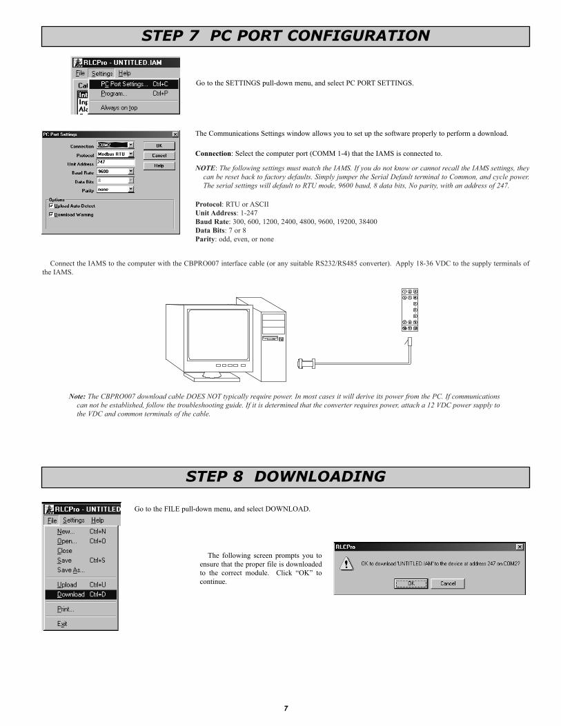
STEP 7 PC PORT CONFIGURATION
Go to the SETTINGS pull-down menu, and select PC PORT SETTINGS.
The Communications Settings window allows you to set up the software properly to perform a download.
Connection: Select the computer port (COMM 1-4) that the IAMS is connected to.
NOTE: The following settings must match the IAMS. If you do not know or cannot recall the IAMS settings, theycan be reset back to factory defaults. Simply jumper the Serial Default terminal to Common, and cycle power.The serial settings will default to RTU mode, 9600 baud, 8 data bits, No parity, with an address of 247.
Protocol: RTU or ASCIIUnit Address: 1-247Baud Rate: 300, 600, 1200, 2400, 4800, 9600, 19200, 38400Data Bits: 7 or 8Parity: odd, even, or none
Connect the IAMS to the computer with the CBPRO007 interface cable (or any suitable RS232/RS485 converter). Apply 18-36 VDC to the supply terminals ofthe IAMS.
Note: The CBPRO007 download cable DOES NOT typically require power. In most cases it will derive its power from the PC. If communicationscan not be established, follow the troubleshooting guide. If it is determined that the converter requires power, attach a 12 VDC power supply tothe VDC and common terminals of the cable.
STEP 8 DOWNLOADING
Go to the FILE pull-down menu, and select DOWNLOAD.
The following screen prompts you toensure that the proper file is downloadedto the correct module. Click “OK” tocontinue.

8
The IAMS is fully calibrated from the factory. Voltage or Current range calibration is recommendedevery two years. Internal ADC calibration is not recommended unless the voltage or current values arestill incorrect after their calibration. If the ADC calibration is performed, the voltage or currentcalibration must be performed. Each input range has its’ own minimum and maximum ADC references(registers 40005 and 40006) which are recalled when the range is selected. This allows independentcalibration for the desired range. Calibration may be performed via MODBUS commands, or by usingSFIMS software.
Allow the IAMS to warm up for 30 minutes minimum, and follow the manufacturer’s warm-upprocedure for the calibration source.Note: Calibration requires a precision signal source with an accuracy of 0.025%, and must be capable
of generating the full span of the range to be calibrated. When using SFIMS for calibration, connectthe signal source to the IAMS, select the proper range in the software, and press the Calibrate button.Follow the calibration procedures in the software.
STEP 11 CALIBRATION
STEP 9 SCRATCH PAD MEMORY
STEP 10 VIEW REGISTERS
The Scratch Pad category can be used to read or write to the Scratch Pad memory locations (41101-41116). The Scratch Pad locations can be used to store user information.
Data Format: Allows registers to be viewed in decimal or hexadecimal format.
Upload: The Upload button causes SFIMS software to read the Scratch Pad registers from the module.
Download: The Download button causes SFIMS software to write to the Scratch Pad registers in themodule.
Note: Downloading new values to the module Scratch Pad locations overwrites the information that iscurrently stored in those registers.
The View Registers category can be used as a method of diagnostics. Use the IAMS Register Tableas a reference of register assignments and data.
First Register: This specifies the first, or only, register to be read in a block.
# of Registers: This is the length of the block to be read. The module supports block read and writecommands up to 16 registers in length.
Data Format: Allows registers to be viewed in decimal or hexadecimal format.
Read: Clicking the Read button causes SFIMS software to read the selected register from the module.
Write: Clicking the Write button causes SFIMS software to write the selected registers to the module.
Note: The Write button overwrites the existing register values, and may change the module setup and operation.

9
TROUBLESHOOTINGPROBLEM CAUSE REMEDIES
Green LED will not light Module power Verify module power connections and level
Process Value not changing Input Signal Check input signal connections and level
Process Value not changing or incorrect Incorrect scaling Check input setup, scaling values, and re-download
Alarms disabled Alarm threshold over range*; checksumerror; ADC overrange
Process Value stays at 32001 or -32001Check input signal connections and levelCheck Input setup, and re-download
Process Value stays at 32002 or -32002Check input signal connections and levelCheck Input Setup, and re-downloadPerform calibration procedure
Flashing LEDs, alarms disabled Parameter checksum*, loss of parametersettings
Re-download SFIMS file (reconfigures each parameter)
Flashing LEDs, alarms disabled Calibration checksum* Perform calibration procedure
Will not communicate
NOTE: The IAMS’ serial settings must match the device that it is communicating with. If you do not know orcannot recall the IAMS settings, they can be reset back to factory defaults. Simply jumper the Serial Default terminalto Common, and cycle power. The serial settings will default to RTU mode, 9600 baud, 8 data bits, no parity, withan address of 247.
Incorrect serial settings (IAMS port)Incorrect serial settings (computer port)Incorrect wiring
ADC over range* due to:Incorrect input signalIncorrect Input SetupImproper Calibration
Gain/Offset over range* due to:Incorrect input signalIncorrect Input setup scaling
Adjust alarm Setpoint and Hysteresis to ensure triggerpoint is within -32,000 - +32,000 (See Alarm setup)
Verify IAMS communications setupGo to pull down menu SETTINGS, PC PORT SETTINGSTry switching A+ and B- linesProvide a common connection
* Can be monitored by accessing coils 9-14, or register 40022.For further technical assistance, contact technical support.

10
INSTALLATIONThe unit is equipped with a universal mounting foot for attachment to standard DIN style mounting rails, including G profile rail
according to EN50035 - G32 , and top hat (T) profile rail according to EN50022 - 35 x 7.5 and - 35 x 15. The unit should be installed in alocation that does not exceed the maximum operating temperature and provides good air circulation. Placing the unit near devices thatgenerate excessive heat should be avoided.
G Rail InstallationTo install the IAMS on a “G”
style DIN rail, angle the moduleso that the upper groove of the“foot” catches under the lip of thetop rail. Push the module towardthe rail until it snaps into place.To remove a module from therail, push up on the bottom of themodule while pulling out andaway from the rail.
T Rail InstallationTo install the IAMS on a “T”
style rail, angle the module sothat the top groove of the “foot”is located over the lip of the toprail. Push the module toward therail until it snaps into place. Toremove a module from the rail,insert a screwdriver into the sloton the bottom of the “foot”, andpry upwards on the module untilit releases from the rail.
APPLICATIONUntreated waste needed to be pumped up a hill to a treatment
center. To prevent undesirable shut downs, a backup pump anda flow transducer were installed in the line. The operatorneeded the ability to monitor the flow, as well as the ability tochange setpoints from the main station, located 4000 feet away.The temperature within the pumping station was not controlled.
The IAMS was installed because of the size, operatingtemperature range, serial communications, and the ability tocontrol the pumps. When the flow is below a certain level, theIAMS switches the Main Pump off, and the Backup Pump on.Operators can monitor the flow and change the setpoints fromthe main building using a PC acquisition program with aMODBUS driver.

11
MODBUS INFORMATIONThe remaining sections of this bulletin list IAMS Register Format information and MODBUS conformity.
MODBUS SUPPORTED FUNCTION CODES
FC01: Read Coils 1. Valid coil addresses are 1-16.2. Only 16 coils can be requested at one time.3. Block starting point can not exceed coil 14.
FC05: Force Single Coil1. Valid write (force) coil addresses are 1-10.2. <8001>HEX is echoed back that the coil did not change during the request to
write to a read only coil.
FC15: Force Multiple Coils1. Valid write (force) coil addresses are 1-10.2. Block starting point can not exceed coil 10.3. If a multiple write includes read only coils, then only the write coils
will change.
FC03: Read Holding Registers 1. Valid addresses are 40001-40026, 41001-41010, 41101-41116.2. Only 16 registers can be requested at one time.3. Block starting point can not exceed the register boundaries.4. <8000>HEX is returned in registers beyond the boundaries.5. Holding registers are a mirror of Input registers.
FC06: Preset Single Register1. Valid write (preset) addresses are 40007-40026, 41101-41116.2. <8001>HEX is echoed back that the register did not change during the
request to write to a read only register.3. If the write value exceeds the register limit (see Register Table), then that
register value changes to its exceeded high or low limit. It is also returned inthe response.
FC16: Preset Multiple Registers1. Valid write (force) register addresses are 40007-40026, 41101-41116.2. No response is given with an attempt to write to more than 16 registers at a time.3. Block starting point can not exceed the read and write boundaries.4. If a multiple write includes read only registers, then only the write registers
will change.5. If the write value exceeds the register limit (see Register Table), then that
register value changes to its exceeded high or low limit.
FC04: Read Input Registers1. Valid addresses are 30001-30026, 31001-31010, 31101-31116.2. Only 16 registers can be requested at one time.3. Block starting point can not exceed register boundaries.4. <8000>HEX is returned in registers beyond the boundaries.5. Input registers are a mirror of Holding registers.
FC08: DiagnosticsThe following is sent upon FC08 request:Unit Address, 08 (FC code), 04 (byte count), “Total Comms” count, “Total Good Comms” count, checksum of the string.“Total Comms” is the total number of messages received that were addressed to
the IAMS. “Total Good Comms” is the total messages received by the IAMSwith good address, parity and checksum. Both counters are reset to 0 uponresponse to FC08.
FC17: Report Slave IDThe following is sent upon FC17 request:Unit Address, 17 (FC code), RLC-IAMS3535, 0100 (for code version 1.00), 16
(number of read supported registers), 16 (number of writes supportedregisters), 16 (number of registers available for GUID/ Scratch pad memory),checksum of the string.
The following is the HEX of the above (with unit address of 247):<F7><11><14><52><4C><43><2D><49><41><4D><53><33><35><33><3
5><01><00><00><10><00><10><00><10><A5><F7>
SUPPORTED EXCEPTION CODES
01: Illegal Function Issued whenever the requested function is not implemented in the unit.
02: Illegal Data AddressIssued whenever an attempt is made to access a single register or coil that
does not exist (outside the implemented space) or to access a block of registersor coils that falls completely outside the implemented space.
03: Illegal Data ValueIssued when an attempt is made to read or write more registers or coils than
the unit can handle in one request.
07: Negative AcknowledgeIssued when a write to coil or register is attempted with an invalid string length.
CHECKSUM ERRORS1. Calibration checksum covers the E2 PROM that contains calibration values
for all ranges. When a calibration checksum error occurs, coil 10 becomes a1. (See Coils Table)
2. Parameter checksum covers the E2 PROM that contains the stored Holdingregister settings. When a parameter checksum error occurs, coil 9 becomes a1. (See Coils Table)
3. All LEDs will flash as long as either error occurs.4. The alarms are disabled as long as either error occurs.5. Either error can be cleared or activated manually by writing to the appropriate
coil. (This does not correct the reason for the error. It may be necessary toreconfigure or calibrate.)
6. Both checksums are verified at power up.
CALIBRATIONADC (Internal)1. Connect the signal source to proper IAMS terminals.2. Apply 0 V or 0 mA to self calibrate.3. To start calibration, enter <7777>HEX into Holding register 40026.4. To start ADC calibration, enter <0001>HEX into Holding register 40026.5. To end calibration, enter <0000>HEX if not continuing with voltage or
current calibration.
Voltage or Current1. Connect the signal source to proper IAMS terminals.2. Enter desired range to be calibrated into Holding register 40007.3. To start calibration, enter <7777>HEX into Holding register 40026.4. Apply 0 voltage or 0 current and enter <0002>HEX into Holding
register 40026.5. Apply maximum limit of selected range and enter <0003>HEX into Holding
register 40026.6. Repeat all of steps 2, 4, and 5 for each range to be calibrated, changing the
source connecting to the proper IAMS terminals as needed.7. To end calibration, enter <0000>HEX into Holding register 40026.

12
REGISTERADDRESS * REGISTER NAME LOW LIMIT† HIGH LIMIT† ACCESS COMMENTS
40001 ADC reading N/A N/A Read Only ADC (Analog to Digital Converter) reading of present input level.
40002 Process Value N/A N/A Read Only Process Value (with gain and offset) of present input level.
40003 Floating Point LO N/A N/A Read Only IEEE Standard 754 Floating Decimal Point, low order of Process Value. (Allows32 bit accuracy for external monitoring.)
40004 Floating Point HI N/A N/A Read Only IEEE Standard 754 Floating Decimal Point, high order of Process Value. (Allows32 bit accuracy for external monitoring.)
40005 Min. ADC Reference N/A N/A Read Only ADC reading at minimum input established during calibration.
40006 Max. ADC Reference N/A N/A Read Only ADC reading at maximum input established during calibration.
40007 Input Range 0 17 Read/Write See Input Range Register Table.
40008 Filter Band 0 32000 Read/Write See Filter Band explanation.
40009 Filter Response Time 0 1000 Read/Write See Filter Response Time explanation (1 = 0.1 second).
40010 Gain Value -32000 32000 Read/Write See Offset and Gain explanation (1 = 0.001).
40011 Offset Value -32000 32000 Read/Write See Offset and Gain explanation.
40012 Alarm 2 Mode <0000> <0039> Read/Write See Alarm 1 & 2 Mode Register Table.
40013 Setpoint 2 Value -32000 32000 Read/Write Alarm 2 setpoint value based on Process Value.
40014 Alarm 2 Hysteresis 1 32000 Read/Write Alarm 2 hysteresis value based on Process Value.
40015 Alarm 2 Delay 0 32000 Read/Write Alarm 2 delay trip on time (1 = 1 second).
40016 Alarm 1 Mode <0000> <0034> Read/Write See Alarm 1 & 2 Mode Register Table.
40017 Setpoint 1 Value -32000 32000 Read/Write Alarm 1 setpoint value based on Process Value.
40018 Alarm 1 Hysteresis 1 32000 Read/Write Alarm 1 hysteresis value based on Process Value.
40019 Alarm 1 Delay 0 32000 Read/Write Alarm 1 delay trip on time (1 = 1 second).
40020 Transmit Delay 1 255 Read/Write Delay before serial transmission (1 = 1 msec). See Transmit Delay Explanation.
40021 Node (Unit) Address 1 247 Read/Write Node serial IAMS address.
40022 Error Coils <0000> <0003> Read/Write Mirror of Coils 9-14. See Coil Table.
40023 Comm. Coils <0020> <00FF> Read/Write Mirror of Coils 1-7. See Coil Table and Communication Table.
40024 Alarm 1 State 0 1 Read/Write Alarm 1 state. (1 = on)
40025 Alarm 2 State 0 1 Read/Write Alarm 2 state. (1 = on)
40026 Factory Calibration <0000> <7777> Read/Write See Calibration explanation.
41001- 41010 Slave ID See FC17. See FC17. Read Only IAMS-3535, 0100 (ver. 1.00), 16 reads, 16 writes, 16 scratch. It is possible thatthe version value is higher.
41101- 41116 GUID/Scratch <0000> <FFFF> Read/Write This area is for the user to store any related information.This register area does not affect IAMS operations.
COIL ADDRESS COIL NAME ACCESS COMMENTS
1 Baud B0 Read/Write See Communication Register and Coils Table.2 Baud B1 Read/Write See Communication Register and Coils Table.3 Baud B2 Read/Write See Communication Register and Coils Table.4 Parity B3 Read/Write See Communication Register and Coils Table.5 Parity B4 Read/Write See Communication Register and Coils Table.6 Data Bits B5 Read/Write See Communication Register and Coils Table.7 Mode B6 Read/Write See Communication Register and Coils Table.8 Change B7 Read/Write “1” = change IAMS communications to above settings.9 P. Checksum Error Read/Write “1” = Parameter checksum error, disables alarms, causes flashing LEDs.
10 C. Checksum Error Read/Write “1” = Calibration checksum error, disables alarms, causes flashing LEDs.11 AL 1 Over Range Read Only “1” = Alarm 1 Threshold over range, disables alarms, causes no LED indication.12 AL 2 Over Range Read Only “1” = Alarm 2 Threshold over range, disables alarms, causes no LED indication.13 ADC Over Range Read Only “1” = ADC over range, causes Process Value to be ±32002, disables alarms.14 G/O Over Range Read Only “1” = Gain and Offset over range, causes Process Value to be ±32001.15 Not used Read Only “0” always.16 Not used Read Only “0” always.
REGISTER TABLEThe below limits are shown as Integers or HEX < > values. Read and write functions can be performed in either Integers or HEX as long as the conversion was
done correctly. Negative numbers are represented by two’s complement.
COILS TABLE (COMMUNICATION AND ERRORS)
* For Input Registers, replace the 4xxxx with a 3xxxx in the above register address. The 3xxxx are a mirror of the 4xxxx Holding Registers.† An attempt to exceed a limit will set the register to its high or low limit value.
Coils 1-7 mirror register 40023 and Coils 9-14 mirror register 40022.

13
RANGE NUMBER SPAN/TYPE RANGE NUMBER SPAN/TYPE RANGE NUMBER SPAN/TYPE
0 0-20 mV 6 0-2 V 12 0-2 mA1 0-50 mV 7 0-5 V 13 0-5 mA2 0-100 mV 8 0-10 V 14 0-10 mA3 0-200 mV 9 0-20 V 15 0-20 mA4 0-500 mV 10 0-50 V 16 0-50 mA5 0-1 V 11 0-100 V 17 0-100 mA
ALARM 1 (40012) & 2 (40016) MODE REGISTER TABLE
INPUT RANGE REGISTER (40007) TABLE
Examples:Alarm 1 (40016):
Stand-by off, Latch on = 0 0 0 1 <1 >Absolute Lo, Balanced = 0 0 1 0 < 2>
<12>Alarm 2 (40012):
Stand-by on, Latch off = 0 0 1 0 <2 >Band Outside = 1 0 0 1 < 9>
<29>
COMMUNICATIONS REGISTER (40023) AND COILS 1-8 TABLE
* When reading register 40023, B7 will be a 0. When writing (changing IAMS communications to the new setting), change B7 to a 1.
Mode Parity Baud Coil 8B7*
Coil 7B6
Coil 6B5
Coil 5B4
Coil 4B3
Coil 3B2
Coil 2B1
Coil 1B0
Coil 8 =0HEX
Coil 8 =1HEX
RTU 8N1,2 300 0 / 1 0 1 0 0 0 0 0 <20> <A0>
RTU 8N1,2 600 0 / 1 0 1 0 0 0 0 1 <21> <A1>
RTU 8N1,2 1200 0 / 1 0 1 0 0 0 1 0 <22> <A2>
RTU 8N1,2 2400 0 / 1 0 1 0 0 0 1 1 <23> <A3>
RTU 8N1,2 4800 0 / 1 0 1 0 0 1 0 0 <24> <A4>
RTU 8N1,2 9600 0 / 1 0 1 0 0 1 0 1 <25> <A5>
RTU 8N1,2 19200 0 / 1 0 1 0 0 1 1 0 <26> <A6>
RTU 8N1,2 38400 0 / 1 0 1 0 0 1 1 1 <27> <A7>
RTU 8E1 300 0 / 1 0 1 0 1 0 0 0 <28> <A8>
RTU 8E1 600 0 / 1 0 1 0 1 0 0 1 <29> <A9>
RTU 8E1 1200 0 / 1 0 1 0 1 0 1 0 <2A> <AA>
RTU 8E1 2400 0 / 1 0 1 0 1 0 1 1 <2B> <AB>
RTU 8E1 4800 0 / 1 0 1 0 1 1 0 0 <2C> <AC>
RTU 8E1 9600 0 / 1 0 1 0 1 1 0 1 <2D> <AD>
RTU 8E1 19200 0 / 1 0 1 0 1 1 1 0 <2E> <AE>
RTU 8E1 38400 0 / 1 0 1 0 1 1 1 1 <2F> <AF>
RTU 8O1 300 0 / 1 0 1 1 1 0 0 0 <38> <B8>
RTU 8O1 600 0 / 1 0 1 1 1 0 0 1 <39> <B9>
RTU 8O1 1200 0 / 1 0 1 1 1 0 1 0 <3A> <BA>
RTU 8O1 2400 0 / 1 0 1 1 1 0 1 1 <3B> <BB>
RTU 8O1 4800 0 / 1 0 1 1 1 1 0 0 <3C> <BC>
RTU 8O1 9600 0 / 1 0 1 1 1 1 0 1 <3D> <BD>
RTU 8O1 19200 0 / 1 0 1 1 1 1 1 0 <3E> <BE>
RTU 8O1 38400 0 / 1 0 1 1 1 1 1 1 <3F> <BF>
LatchedOff=Auto
2nd NibbleHEXStand By B7 B6 B5
off off 0 0 0 0 <0 >
off on 0 0 0 1 <1 >
on off 0 0 1 0 <2 >
on on 0 0 1 1 <3 >
B4
< 9>100129 Band Outside
< 6>011026Deviation Lo
< 5>101025Deviation Hi
< 4>0010214Absolute Lo, unbalanced
< 3>1100213Absolute Hi, unbalanced
< 2>0100212Absolute Lo, balanced
< 1>1000211Absolute Hi, balanced
< 0>0000210Manual
1st NibbleHEXB0B1B2B3ALARMSMODEACTION
See Setpoint Alarm Figures, Page 6, for illustrations of alarm operation.

14
COMMUNICATIONS REGISTER (40023) AND COILS 1-8 TABLE (continued)
Mode Parity Baud Coil 8B7 *
Coil 7B6
Coil 6B5
Coil 5B4
Coil 4B3
Coil 3B2
Coil 2B1
Coil 1B0
Coil 8 =0HEX
Coil 8 =1HEX
ASCII 7N2 300 0 / 1 1 0 0 0 0 0 0 <40> <C0>
ASCII 7N2 600 0 / 1 1 0 0 0 0 0 1 <41> <C1>
ASCII 7N2 1200 0 / 1 1 0 0 0 0 1 0 <42> <C2>
ASCII 7N2 2400 0 / 1 1 0 0 0 0 1 1 <43> <C3>
ASCII 7N2 4800 0 / 1 1 0 0 0 1 0 0 <44> <C4>
ASCII 7N2 9600 0 / 1 1 0 0 0 1 0 1 <45> <C5>
ASCII 7N2 19200 0 / 1 1 0 0 0 1 1 0 <46> <C6>
ASCII 7N2 38400 0 / 1 1 0 0 0 1 1 1 <47> <C7>
ASCII 7E1 300 0 / 1 1 0 0 1 0 0 0 <48> <C8>
ASCII 7E1 600 0 / 1 1 0 0 1 0 0 1 <49> <C9>
ASCII 7E1 1200 0 / 1 1 0 0 1 0 1 0 <4A> <CA>
ASCII 7E1 2400 0 / 1 1 0 0 1 0 1 1 <4B> <CB>
ASCII 7E1 4800 0 / 1 1 0 0 1 1 0 0 <4C> <CC>
ASCII 7E1 9600 0 / 1 1 0 0 1 1 0 1 <4D> <CD>
ASCII 7E1 19200 0 / 1 1 0 0 1 1 1 0 <4E> <CE>
ASCII 7E1 38400 0 / 1 1 0 0 1 1 1 1 <4F> <CF>
ASCII 7O1 300 0 / 1 1 0 1 1 0 0 0 <58> <D8>
ASCII 7O1 600 0 / 1 1 0 1 1 0 0 1 <59> <D9>
ASCII 7O1 1200 0 / 1 1 0 1 1 0 1 0 <5A> <DA>
ASCII 7O1 2400 0 / 1 1 0 1 1 0 1 1 <5B> <DB>
ASCII 7O1 4800 0 / 1 1 0 1 1 1 0 0 <5C> <DC>
ASCII 7O1 9600 0 / 1 1 0 1 1 1 0 1 <5D> <DD>
ASCII 7O1 19200 0 / 1 1 0 1 1 1 1 0 <5E> <DE>
ASCII 7O1 38400 0 / 1 1 0 1 1 1 1 1 <5F> <DF>
ASCII 8N1 300 0 / 1 1 1 0 0 0 0 0 <60> <E0>
ASCII 8N1 600 0 / 1 1 1 0 0 0 0 1 <61> <E1>
ASCII 8N1 1200 0 / 1 1 1 0 0 0 1 0 <62> <E2>
ASCII 8N1 2400 0 / 1 1 1 0 0 0 1 1 <63> <E3>
ASCII 8N1 4800 0 / 1 1 1 0 0 1 0 0 <64> <E4>
ASCII 8N1 9600 0 / 1 1 1 0 0 1 0 1 <65> <E5>
ASCII 8N1 19200 0 / 1 1 1 0 0 1 1 0 <66> <E6>
ASCII 8N1 38400 0 / 1 1 1 0 0 1 1 1 <67> <E7>
ASCII 8E1 300 0 / 1 1 1 0 1 0 0 0 <68> <E8>
ASCII 8E1 600 0 / 1 1 1 0 1 0 0 1 <69> <E9>
ASCII 8E1 1200 0 / 1 1 1 0 1 0 1 0 <6A> <EA>
ASCII 8E1 2400 0 / 1 1 1 0 1 0 1 1 <6B> <EB>
ASCII 8E1 4800 0 / 1 1 1 0 1 1 0 0 <6C> <EC>
ASCII 8E1 9600 0 / 1 1 1 0 1 1 0 1 <6D> <ED>
ASCII 8E1 19200 0 / 1 1 1 0 1 1 1 0 <6E> <EE>
ASCII 8E1 38400 0 / 1 1 1 0 1 1 1 1 <6F> <EF>
ASCII 8O1 300 0 / 1 1 1 1 1 0 0 0 <78> <F8>
ASCII 8O1 600 0 / 1 1 1 1 1 0 0 1 <79> <F9>
ASCII 8O1 1200 0 / 1 1 1 1 1 0 1 0 <7A> <FA>
ASCII 8O1 2400 0 / 1 1 1 1 1 0 1 1 <7B> <FB>
ASCII 8O1 4800 0 / 1 1 1 1 1 1 0 0 <7C> <FC>
ASCII 8O1 9600 0 / 1 1 1 1 1 1 0 1 <7D> <FD>
ASCII 8O1 19200 0 / 1 1 1 1 1 1 1 0 <7E> <FE>
ASCII 8O1 38400 0 / 1 1 1 1 1 1 1 1 <7F> <FF>
* When reading register 40023, B7 will be a 0. When writing (changing IAMS communications to the new setting), change B7 to a 1.

15
This page intentionally left blank

LIMITED WARRANTYThe Company warrants the products it manufactures against defects in materials and workmanshipfor a period limited to two years from the date of shipment, provided the products have been stored,handled, installed, and used under proper conditions. The Company’s liability under this limitedwarranty shall extend only to the repair or replacement of a defective product, at The Company’soption. The Company disclaims all liability for any affirmation, promise or representation withrespect to the products.The customer agrees to hold Red Lion Controls harmless from, defend, and indemnify RLC againstdamages, claims, and expenses arising out of subsequent sales of RLC products or productscontaining components manufactured by RLC and based upon personal injuries, deaths, propertydamage, lost profits, and other matters which Buyer, its employees, or sub-contractors are or may beto any extent liable, including without limitation penalties imposed by the Consumer Product SafetyAct (P.L. 92-573) and liability imposed upon any person pursuant to the Magnuson-Moss WarrantyAct (P.L. 93-637), as now in effect or as amended hereafter.No warranties expressed or implied are created with respect to The Company’s products except thoseexpressly contained herein. The Customer acknowledges the disclaimers and limitations containedherein and relies on no other warranties or affirmations.
Red Lion Controls
20 Willow Springs Circle
York PA 17406
Tel +1 (717) 767-6511
Fax +1 (717) 764-0839
Red Lion Controls AP
31, Kaki Bukit Road 3,
#06-04/05 TechLink
Singapore 417818
Tel +65 6744-6613
Fax +65 6743-3360
Red Lion Controls BV
Basicweg 11b
NL - 3821 BR Amersfoort
Tel +31 (0) 334 723 225
Fax +31 (0) 334 893 793