building structures with grc - irbnet.de · cib world building congress, april 2001, wellington,...
TRANSCRIPT
CIB World Building Congress, April 2001, Wellington, New Zealand Page 1 of 11 Paper: NOV 02
BUILDING STRUCTURES WITH GRC
FERNANDO A. BRANCO, JOÃO FERREIRA, JORGE DE BRITO and JOSÉ R. SANTOS
Civil Engineering Department, Instituto Superior Técnico, 1049-001 Lisboa, Portugal ABSTRACT GRC - Glass Fibre Reinforced Concrete - is a material made of a cementitious matrix composed of cement, sand, water and admixtures, in which short length glass fibres are dispersed. Till now it has been widely used in the construction industry for non-structural elements, namely façade panels. In this paper the results of a research project are presented where this material was applied to the building of structural elements, exemplified by telecommunications towers 30m high. Here the lightness and high tensile strength advantages of the GRC were associated with carbon and stainless steel reinforcement, leading to an innovative material with high durability characteristics. KEYWORDS New materials; GRC; structures; glass fibre; carbon tendons INTRODUCTION GRC - Glass Fibre Reinforced Concrete - consists basically of a cementitious matrix composed of cement, sand, water and admixtures, in which short length glass fibres are dispersed. The effect of these fibres is reflected in the increase of the tension and impact strength of the material. This material has been used for over thirty years in non-structural elements like façade panels (about 80 % of the GRC production), piping for sanitation network systems, decorative non-recoverable formwork and other products (Bentur, 1990). In the early times of the GRC development one of the most concerning problems was the durability of the glass fibres, which became fragile with time, because of the alkalinity of the cement mortar. Since then significant progress has been made in this area, with the development of new types of alkali resistant glass fibres. Studies to use this material in structural elements were recently developed for the first time within a European funded research project and are here presented (Persano-Adorno, 2000). The structural advantages of GRC arise from a reduced weight and a higher tensile strength as compared with concrete. Besides that and aiming to obtain a corrosion free material, with high durability, the structural elements of this project were also designed with a reinforcement made of carbon tendons and stainless steel. Two main processes of production of GRC were initially analysed, namely the classical projection technique (spray-up) and the premixing. The later proved much better for the use in structural elements due to the homogeneity of the material obtained and the high speed of production. The industries involved in the research project adopted this last technique, which led to the development of new construction procedures. To characterize the material, initially several experimental tests were performed with premix GRC to determine its mechanical strength, Young modulus, creep and shrinkage behaviour and stress-strain diagrams in tension, compression and under cyclic loading. The material was tested either plain or with glass fibres, and reinforced with carbon and/or glass tendons. The GRC compositions were also
CIB World Building Congress, April 2001, Wellington, New Zealand Page 2 of 11 Paper: NOV 02
studied in terms of length and percentage of fibres to obtain their optimisation. The ageing effect in the glass fibres was also analysed with accelerated ageing tests. All these tests led to a characterization of the production conditions to obtain optimised material properties. This material was then applied to the production of precast telecommunications towers, 30 m high. The towers were longitudinally prestressed, and reinforced with carbon tendons and/or stainless steel grids. Several prototypes of these structures were tested with elastic load tests and collapse tests, based on which the design models were checked, leading to a safe design of these structures. Besides the structural capability of the towers to support the antennas, the design considered also some restrictions related to the electro-magnetic interferences. By using non-magnetic materials, like the fibre tendons or the stainless steel bars, all these requirements were fulfilled, showing significant advantages for this structural solution. TYPES OF GRC There are two main production techniques of GRC, usually referred as spray-up (or shotcreted) and premix, which are now described. Spray-up method In the process of producing GRC by spray-up (or shotcreted), the mortar (cement, sand, water and additives) is initially made without any fibres, which are then mixed only at the jet of the spray gun. The two components are then shotcreted against (or over) the mould of the element that is being produced (Curiger, 1995). The spray gun can be operated manually or be mounted on automatic equipment that does the whole operation. The mortar is pumped to the spray gun where it is dispersed into small particles by the use of compressed air. The glass fibre tendons are cut within the spray gun to the required size (typically between 25 mm and 40 mm) through a rotating drum system provided with blades. This system impels the already cut glass tendons towards the core of the mortar jet coming out of the spray gun, so that within the material spread over the mould the fibres are evenly dispersed. The mortar typically has a sand / cement ratio of up to 1/1 and a water / cement ratio of 0.33. The water / cement ratio must be kept as low as possible (as long as it keeps the necessary workability and the capacity of mixing of the fibres), because its increase implies a loss of strength of the product. Fluidisers can be added in order to obtain a higher workability with less water quantity. The typical percentage of the fibres in the composite is about 5 %, in terms of weight. Manual shotcreting method - Here the operator holds the spray gun in his hand, moving it from side to side throughout the mould, directing the jet perpendicular to the surface until the GRC layer achieves the predetermined thickness (Knowles, 1987). The subsequent compaction with a cylindrical roll guarantees the GRC moulding in the form, the impregnation of the fibres within the mortar, the removal of the air retained within the mix and the creation of an adequate density. After this compaction, the surface can be smoothed with a trowel. The control of the thickness can be made using a needle of a predetermined length, inserting it in GRC layer until it reaches the mould surface. The manual method allows an average pace of shotcreting of around 10 kg to 12 kg of GRC per minute. The final product has a smooth face (the one against the mould) and another rough (the outside one) finished with the cylindrical roll or with the trowel.
CIB World Building Congress, April 2001, Wellington, New Zealand Page 3 of 11 Paper: NOV 02
After the shotcreting, the products are usually covered with a polyethylene sheet and demoulded the next day, after which they are subject to a standard cure. This method requires a lot of workmanship but allows the production of elements with complex shapes and is extremely versatile. The manual shotcreting is used mostly in the production of a great variety of elements, such as facade panels, agricultural components, moulds and piping. Automatic shotcreting method - Here the procedure is basically the same as in the manual one but totally mechanised. In this method, the moulds are moved along cylinders on an assembly line, going below a unit where the spray gun is installed. With the automatic method, it is possible to achieve great shotcreting speeds of around 25 kg to 30 kg of GRC per minute. The speed of the moulds and of the spay gun movements, the mortar flow volume and the quantity of fibres have to be adjusted in order to guarantee the adequate dosage and homogeneity of the mix and the uniformity of GRC depth in the mould. This method is particularly adequate for the production of elements essentially plane, namely facade elements with a single layer or of the sandwich type. Non-plane elements, such as pipes and small channels, can also be produced with this method. Premix Technique In the GRC production method by pre-mixture, GRC components - cement, sand, water, admixtures and pre-cut fibres - are all previously mixed. To produce the GRC paste with the adequate quality, the mixing must be made in two stages. In the first one, a mortar with the necessary workability, allowing a uniform addition of the fibres, must be prepared. The second stage consists on the dispersion of the fibres within the mortar. The two stages are preferably performed in the same container (Boon, 1998). The dosage of premix GRC depends on the product that is being made. Nevertheless, the typical values for the sand / cement and water / cement ratios are, respectively, 0.5/1 and 0.35. Generally, fluidisers are used in order to achieve the necessary workability. The quantity of fibres added to the mortar is usually around 3.5 %, in terms of weight, but it is possible to go up to 4 %. The length of the fibres is generally around 12 mm as, above this value, there is an excessive reduction of the mix’s workability. The maximum permissible length of the fibres is 25 mm. The addition of the fibres must be done only at the end of the mixing process in order to avoid its degradation, as this fragile type of fibre is susceptible to be damaged by the mixing process. The production method of elements with premix GRC may involve several techniques such as injection and vibration, shotcreting, pressing and others. The most usual technique is the injection, being the shotcreting also widely used. The premix shotcreting technique, showed in Figure 1, is very similar to the spray up technique. Is this case, however, the jet is made by the former premixed GRC, instead of mixing the fibres with the mortar just at the spray gun jet. The injection technique is very similar to the making of precast concrete, consisting in the deposition of GRC mortar in an open mould or a double-walled mould being subsequently vibrated in order to homogenise the mortar and to remove the air bubbles trapped. The GRC mortar can be injected using a hose and a peristaltic pump.

CIB World Building Congress, April 2001, Wellington, New Zealand Page 4 of 11 Paper: NOV 02
Figure 1 – Shotcreting premix GRC against mould
EXPERIMENTAL TESTS WITH GRC Several experimental tests have been performed to determine the mechanical properties of the GRC namely its tensile and compression strength, Young modulus, creep and shrinkage behaviour and stress-strain diagrams in tension and compression. The first series of tests analysed the tensile strength of the specimens. The material tested was premix GRC either plain, reinforced with tendons of carbon or glass fibre or reinforced with steel bars. Figure 2 shows one of these specimens, reinforced with carbon fibre tendon and steel bar, after the tensile test.
Figure 2 – GRC specimen reinforced with carbon fibre tendon and steel bar, after the tensile test
CIB World Building Congress, April 2001, Wellington, New Zealand Page 5 of 11 Paper: NOV 02
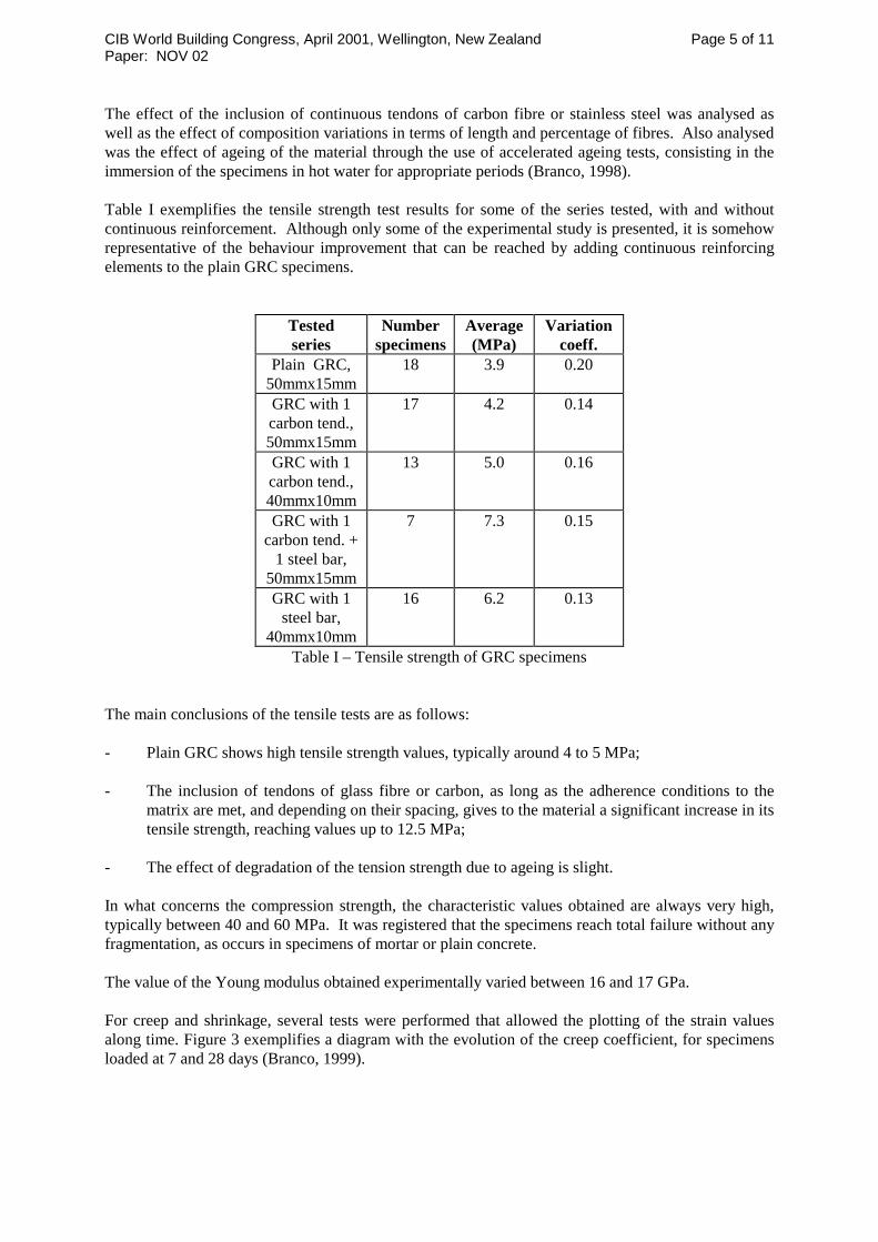
The effect of the inclusion of continuous tendons of carbon fibre or stainless steel was analysed as well as the effect of composition variations in terms of length and percentage of fibres. Also analysed was the effect of ageing of the material through the use of accelerated ageing tests, consisting in the immersion of the specimens in hot water for appropriate periods (Branco, 1998). Table I exemplifies the tensile strength test results for some of the series tested, with and without continuous reinforcement. Although only some of the experimental study is presented, it is somehow representative of the behaviour improvement that can be reached by adding continuous reinforcing elements to the plain GRC specimens.
Tested series
Number specimens
Average (MPa)
Variation coeff.
Plain GRC, 50mmx15mm
18 3.9 0.20
GRC with 1 carbon tend., 50mmx15mm
17 4.2 0.14
GRC with 1 carbon tend., 40mmx10mm
13 5.0 0.16
GRC with 1 carbon tend. +
1 steel bar, 50mmx15mm
7 7.3 0.15
GRC with 1 steel bar,
40mmx10mm
16 6.2 0.13
Table I – Tensile strength of GRC specimens The main conclusions of the tensile tests are as follows: - Plain GRC shows high tensile strength values, typically around 4 to 5 MPa; - The inclusion of tendons of glass fibre or carbon, as long as the adherence conditions to the
matrix are met, and depending on their spacing, gives to the material a significant increase in its tensile strength, reaching values up to 12.5 MPa;
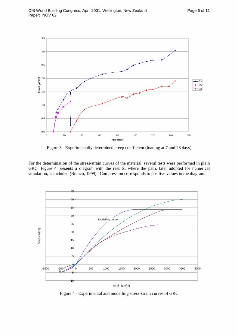
- The effect of degradation of the tension strength due to ageing is slight. In what concerns the compression strength, the characteristic values obtained are always very high, typically between 40 and 60 MPa. It was registered that the specimens reach total failure without any fragmentation, as occurs in specimens of mortar or plain concrete. The value of the Young modulus obtained experimentally varied between 16 and 17 GPa. For creep and shrinkage, several tests were performed that allowed the plotting of the strain values along time. Figure 3 exemplifies a diagram with the evolution of the creep coefficient, for specimens loaded at 7 and 28 days (Branco, 1999).
CIB World Building Congress, April 2001, Wellington, New Zealand Page 6 of 11 Paper: NOV 02
0.0
0.5
1.0
1.5
2.0
2.5
3.0
3.5
0 20 40 60 80 100 120 140 160
Age (days)
Stra
in ( µµ µµ
m/m
)
G3G5G2
Figure 3 - Experimentally determined creep coefficient (loading at 7 and 28 days)
For the determination of the stress-strain curves of the material, several tests were performed in plain GRC. Figure 4 presents a diagram with the results, where the path, later adopted for numerical simulation, is included (Branco, 1999). Compression corresponds to positive values in the diagram.
-10
-5
0
5
10
15
20
25
30
35
40
45
-1000 -500 0 500 1000 1500 2000 2500 3000 3500 4000
Strain (µm/m)
Stre
ss (M
Pa)
Modelling curve
Figure 4 - Experimental and modelling stress-strain curves of GRC
CIB World Building Congress, April 2001, Wellington, New Zealand Page 7 of 11 Paper: NOV 02
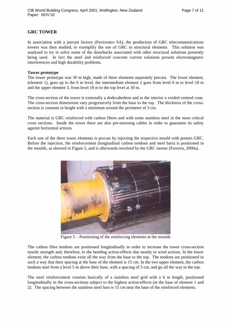
GRC TOWER In association with a precast factory (Pavicentro SA), the production of GRC telecommunications towers was then studied, to exemplify the use of GRC in structural elements. This solution was analysed to try to solve some of the drawbacks associated with other structural solutions presently being used. In fact the steel and reinforced concrete current solutions present electromagnetic interferences and high durability problems. Tower prototype The tower prototype was 30 m high, made of three elements separately precast. The lower element, (element 1), goes up to the 6 m level, the intermediate element 2 goes from level 6 m to level 18 m and the upper element 3, from level 18 m to the top level at 30 m. The cross-section of the tower is externally a dodecahedron and in the interior a voided centred cone. The cross-section dimensions vary progressively from the base to the top. The thickness of the cross-section is constant in height with a minimum around the perimeter of 3 cm. The material is GRC reinforced with carbon fibres and with some stainless steel in the most critical cross sections. Inside the tower there are also pre-stressing cables in order to guarantee its safety against horizontal actions. Each one of the three tower elements is precast by injecting the respective mould with premix GRC. Before the injection, the reinforcement (longitudinal carbon tendons and steel bars) is positioned in the moulds, as showed in Figure 5, and is afterwards involved by the GRC mortar (Ferreira, 2000a).
Figure 5 – Positioning of the reinforcing elements at the moulds
The carbon fibre tendons are positioned longitudinally in order to increase the tower cross-section tensile strength and, therefore, to the bending action-effects due mostly to wind actions. In the lower element, the carbon tendons exist all the way from the base to the top. The tendons are positioned in such a way that their spacing at the base of the element is 15 cm. In the two upper element, the carbon tendons start from a level 5 m above their base, with a spacing of 5 cm, and go all the way to the top. The steel reinforcement consists basically of a stainless steel grid with a 6 m length, positioned longitudinally in the cross-sections subject to the highest action-effects (at the base of element 1 and 2). The spacing between the stainless steel bars is 15 cm near the base of the reinforced elements.
CIB World Building Congress, April 2001, Wellington, New Zealand Page 8 of 11 Paper: NOV 02
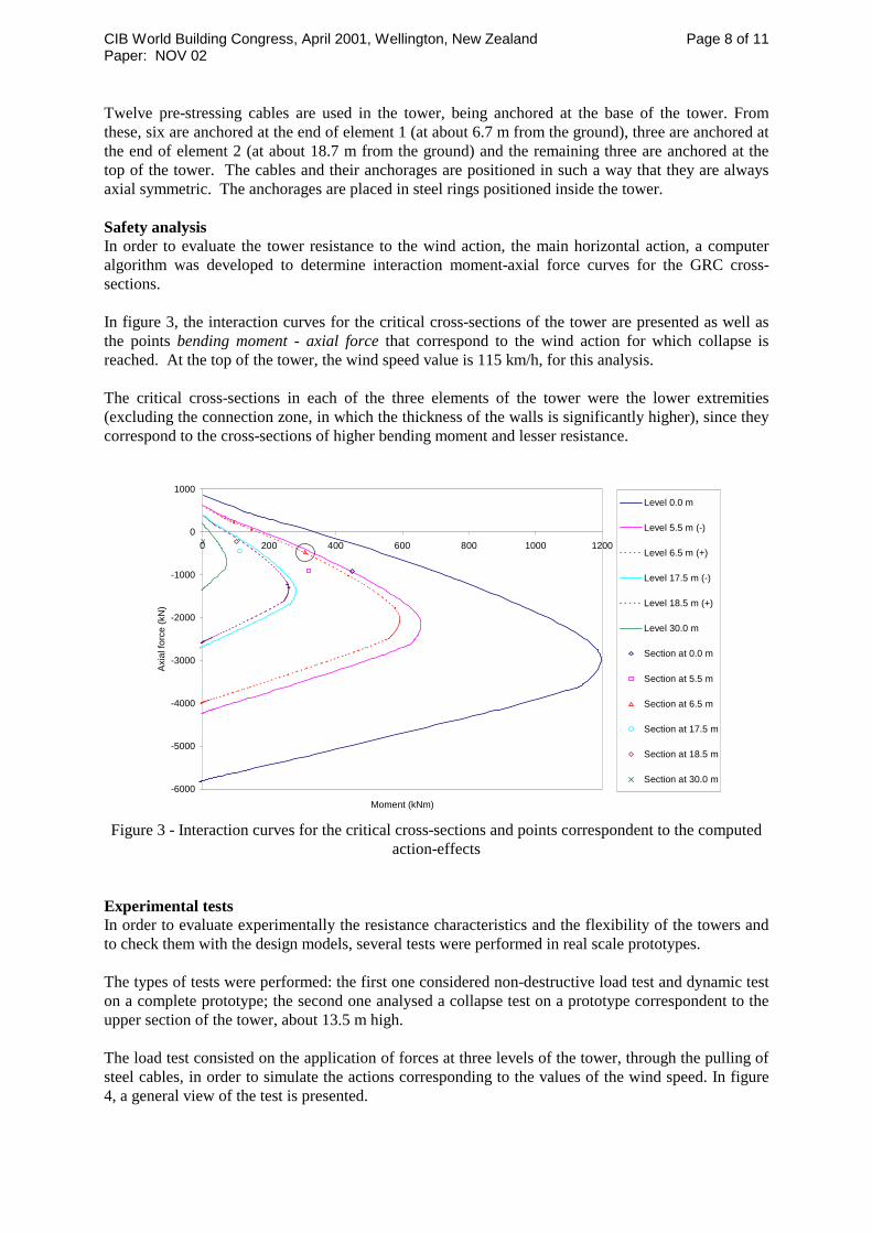
Twelve pre-stressing cables are used in the tower, being anchored at the base of the tower. From these, six are anchored at the end of element 1 (at about 6.7 m from the ground), three are anchored at the end of element 2 (at about 18.7 m from the ground) and the remaining three are anchored at the top of the tower. The cables and their anchorages are positioned in such a way that they are always axial symmetric. The anchorages are placed in steel rings positioned inside the tower. Safety analysis In order to evaluate the tower resistance to the wind action, the main horizontal action, a computer algorithm was developed to determine interaction moment-axial force curves for the GRC cross-sections. In figure 3, the interaction curves for the critical cross-sections of the tower are presented as well as the points bending moment - axial force that correspond to the wind action for which collapse is reached. At the top of the tower, the wind speed value is 115 km/h, for this analysis. The critical cross-sections in each of the three elements of the tower were the lower extremities (excluding the connection zone, in which the thickness of the walls is significantly higher), since they correspond to the cross-sections of higher bending moment and lesser resistance.
-6000
-5000
-4000
-3000
-2000
-1000
0
1000
0 200 400 600 800 1000 1200
Moment (kNm)
Axia
l for
ce (k
N)
Level 0.0 m
Level 5.5 m (-)
Level 6.5 m (+)
Level 17.5 m (-)
Level 18.5 m (+)
Level 30.0 m
Section at 0.0 m
Section at 5.5 m
Section at 6.5 m
Section at 17.5 m
Section at 18.5 m
Section at 30.0 m
Figure 3 - Interaction curves for the critical cross-sections and points correspondent to the computed
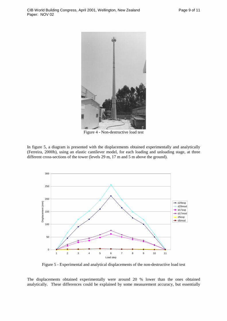
action-effects Experimental tests In order to evaluate experimentally the resistance characteristics and the flexibility of the towers and to check them with the design models, several tests were performed in real scale prototypes. The types of tests were performed: the first one considered non-destructive load test and dynamic test on a complete prototype; the second one analysed a collapse test on a prototype correspondent to the upper section of the tower, about 13.5 m high. The load test consisted on the application of forces at three levels of the tower, through the pulling of steel cables, in order to simulate the actions corresponding to the values of the wind speed. In figure 4, a general view of the test is presented.
CIB World Building Congress, April 2001, Wellington, New Zealand Page 9 of 11 Paper: NOV 02
Figure 4 - Non-destructive load test
In figure 5, a diagram is presented with the displacements obtained experimentally and analytically (Ferreira, 2000b), using an elastic cantilever model, for each loading and unloading stage, at three different cross-sections of the tower (levels 29 m, 17 m and 5 m above the ground).
0
50
100
150
200
250
300
1 2 3 4 5 6 7 8 9 10 11Load step
Dis
plac
emen
t (m
m)
d29expd29modd17expd17modd5expd5mod
Figure 5 - Experimental and analytical displacements of the non-destructive load test
The displacements obtained experimentally were around 20 % lower than the ones obtained analytically. These differences could be explained by some measurement accuracy, but essentially

CIB World Building Congress, April 2001, Wellington, New Zealand Page 10 of 11 Paper: NOV 02
from the additional stiffness arising from the aluminium elements mounted on the tower (metallic staircases). In the dynamic tests, the horizontal vibrating displacements were measured with accelerometers, after the tower has been subjected to a small horizontal excitation. After post-treatment (spectral analysis) of the registered values, the oscillation main frequencies were obtained, corresponding to 1.0 Hz and 3.7 Hz, values similar to the ones obtained with the elastic numerical model. In the collapse test, the tower was subjected to the pulling of a steel cable, until failure was achieved. The collapse occurred by compression in the cross-section located 5.2 meters below the top. In figure 6, a general view of the test is presented. Before collapse occurred, large cracking was observed in the tensile zone. Using the design method with the material properties from the tests, a value of the bending moment at failure equal to the one that did occur was obtained, showing the reliability of the design procedures. In the collapse test the carbon fibres tendons show to be very effective in absorbing tension and their collapse occurred without slipping. The stainless steel bars were located at the bottom of the tower, being their top end, just below the cross section where collapse occurred.
Figure 6 - Collapse load test
CIB World Building Congress, April 2001, Wellington, New Zealand Page 11 of 11 Paper: NOV 02
CONCLUSIONS The use of GRC reinforced with carbon tendons as a structural material proved to be viable, what was exemplified with the production and testing of telecommunications towers 30m high. The material characteristics were experimentally determined and led to values allowing for its use in structural elements, achieving code resistance and flexibility safety levels. The models that have been adopted for the determination of the characteristics of resistance and flexibility and structural dynamic behaviour presented a good correlation with the behaviour obtained during the experimental tests. ACKNOWLEDGEMENTS The authors wish to thank the financial support of the European Commission for the research developed within project “STRUCTA-GRC BES2-5315”. REFERENCES Bentur, A., Mindess, S. 1990. “Fibre reinforced cementitious composites”, Elsevier Applied Science, UK. Boon, D. et al 1998. “Design of thin wall units”, FIP Recommendations, London. Branco, F. et al 1998. “Tensile strength characterisation of GRC specimens” (in Portuguese), Portuguese Conference of Structural Engineering, LNEC, Lisbon. Branco, F. et al 1999. “The use of GRC as a structural material”, Symposium on Mechanics of Composite Materials and Structures, Coimbra. Curiger, P., et al 1995. “Glass fibre reinforced concrete. Practical design and structural analysis”, Beton-Verlag,Dusseldorf. Ferreira, J. et al 2000. “Production of telecommunications towers in GRC”(in Portuguese), Proceedings of the 1st National Congress of The Precast Industry, anipc, Portugal. Ferreira, J. et al 2000. “Structural behaviour of telecommunications towers in GRC” (in Portuguese), Proceedings of the Congress on the Structural Concrete 2000 , Portugal. Knowles, E. S., et al 1987. “Recommended practice on glass fibre reinforced concrete panels”, PCI publication, USA. Persano-Adorno, G. et al 2000. “Structural applications of glass-fibre reinforced concrete components (STRUCTA-GRC)”, final technical report of project CRAFT-BES2-5315”.