building services industrial · chilled & cold water pipework durapipe superflo abs for low...
TRANSCRIPT
INDUSTRIALBUILDING SERVICES
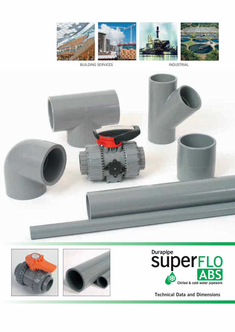
Technical Data and Dimensions
CHILLED & COLD WATER PIPEWORK
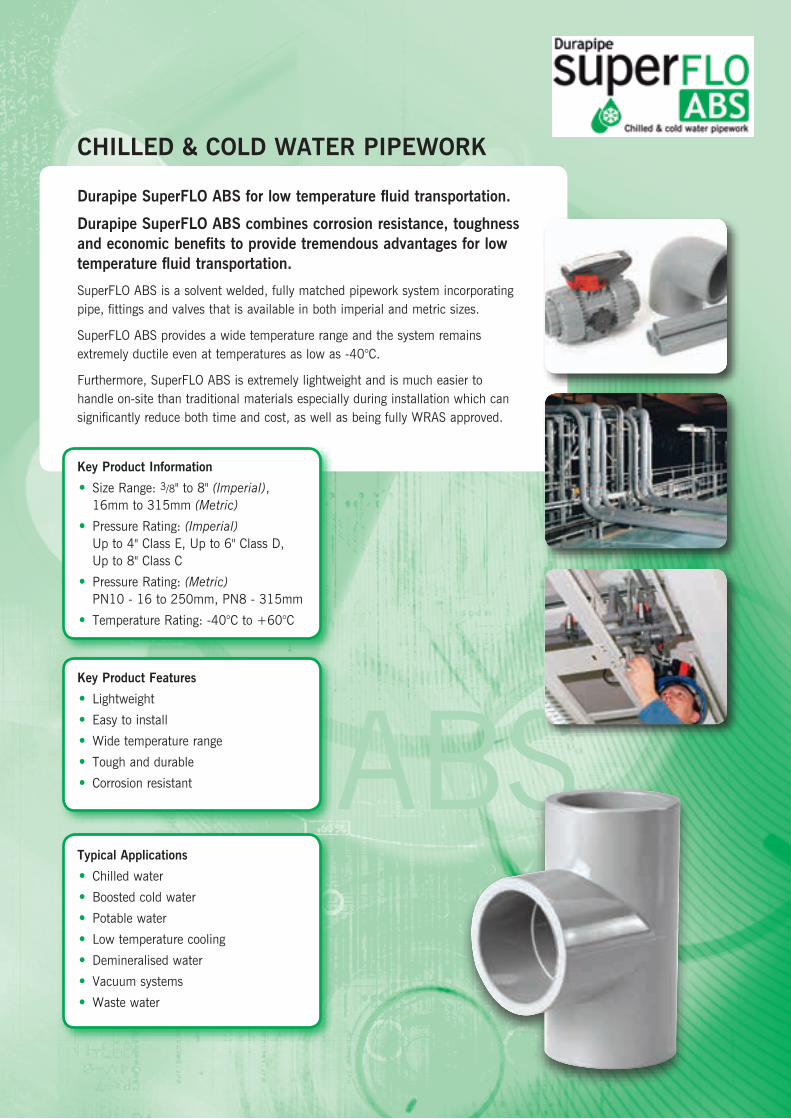
Durapipe SuperFLO ABS for low temperature fluid transportation.
Durapipe SuperFLO ABS combines corrosion resistance, toughness and economic benefits to provide tremendous advantages for low temperature fluid transportation.
SuperFLO ABS is a solvent welded, fully matched pipework system incorporating pipe, fittings and valves that is available in both imperial and metric sizes.
SuperFLO ABS provides a wide temperature range and the system remains extremely ductile even at temperatures as low as -40°C.
Furthermore, SuperFLO ABS is extremely lightweight and is much easier to handle on-site than traditional materials especially during installation which can significantly reduce both time and cost, as well as being fully WRAS approved.
Key Product Information
• Size Range: 3/8" to 8" (Imperial), 16mm to 315mm (Metric)
• Pressure Rating: (Imperial) Up to 4" Class E, Up to 6" Class D, Up to 8" Class C
• Pressure Rating: (Metric) PN10 - 16 to 250mm, PN8 - 315mm
• Temperature Rating: -40°C to +60°C
Typical Applications
• Chilled water
• Boosted cold water
• Potable water
• Low temperature cooling
• Demineralised water
• Vacuum systems
• Waste water
Key Product Features
• Lightweight
• Easy to install
• Wide temperature range
• Tough and durable
• Corrosion resistant ABS
email: [email protected] web: www.durapipe.co.uk 3
Index
SuperFLO ABS Overview ...........................................................4-5Building Services Overview and Case Studies ..............................6-7Industrial Overview and Case Studies .........................................8-9Sustainability .......................................................................10-11Technical Information ...........................................................12-13Maximum pressure/temperature relationship ................................. 12Fittings ..................................................................................... 12Flow calculations ....................................................................... 12Flow Nomogram ........................................................................ 13SuperFLO ABS Jointing Guide ...............................................14-22Procedure ................................................................................. 14Drying times .............................................................................. 15Branch connections .................................................................... 16The use of bushes, reducers and threaded adaptors ....................... 17SuperFLO flexible hoses .............................................................. 17Threaded connections ................................................................. 18Tightening torques for flange bolts in ABS piping systems .............. 18Pipe routing .............................................................................. 19Calculating expansion and contraction .......................................... 19
Additional Important Information ................................................23Comparison of SuperFLO ABS Imperial and Metric Sized Pipe .......24General Information ..............................................................25-27Index to SuperFLO ABS Metric Fittings ..................................28-45SuperFLO ABS Pipe plain ........................................................... 30Sockets plain ............................................................................ 30Reducing bushes plain ............................................................... 31Reducing sockets plain ............................................................... 31Elbows 45° plain ....................................................................... 31Elbows 90° plain ....................................................................... 32Tees 45° plain ........................................................................... 32Tees 90° equal .......................................................................... 32Tees 90° swept plain ................................................................. 33Tees 90° reducing plain ............................................................. 33Bends 90° short radius............................................................... 33Bends 90° long radius ................................................................ 34End caps plain .......................................................................... 34Socket unions plain .................................................................... 34Imperial/metric socket adaptors plain ........................................... 34Male threaded adaptors BSP taper male thread ............................ 35Female threaded adaptors plain spigot/plain socket/ female BSP thread .................................................................. 35Hose adaptors spigot end/hose tail .............................................. 35Female composite unions plain/brass, female BSP parallel thread . 36Male composite unions plain/brass, male BSP taper thread ........... 36Flexible hoses plain spigot, BSP thread ....................................... 36Wall brackets ABS/brass body ..................................................... 37Flanges stub plain serrated ......................................................... 37Flanges blanking ........................................................................ 37Backing rings galvanised mild steel ............................................. 38Flat gaskets for use with stub flanges ........................................... 39Valve support plates galvanised steel ........................................... 39O-Rings .................................................................................... 39
ValvesVKD Double union ball valves ..................................................... 40TKD 3-way ball valves ................................................................ 40VXE Easyfit double union ball valves ............................................ 41VKR Metering ball valves ............................................................ 41SX Easyfit ball check valves ........................................................ 41SA Easyfit air release valves ........................................................ 41RV Y-Type strainers .................................................................... 42VM Diaphragm valves................................................................. 42PR Pressure relief valves ............................................................. 42FK Butterfly valves ..................................................................... 43
AccessoriesCobra pipe clips ......................................................................... 44Rubber lined pipe clips ............................................................... 44One-step solvent cement ............................................................. 44 Eco-cleaner ............................................................................... 45Chamfering and de-burring tools .................................................. 45Pipe cutters ............................................................................... 45
Index to ABS SuperFLO Imperial Fittings ................................46-69SuperFLO ABS Pipe plain ........................................................... 48Sockets plain ............................................................................ 49Reducing bushes plain ............................................................... 49Reducing sockets plain ............................................................... 50Elbows 45° plain ....................................................................... 50Elbows 90° plain ....................................................................... 50Tees 45° plain ........................................................................... 50Tees 90° equal plain .................................................................. 51Tees 90° swept plain ................................................................. 51Tees 90° reducing ..................................................................... 51Bends 221⁄2° long radius ............................................................ 51Bends 45° long radius ................................................................ 52Bends 90° long radius ................................................................ 52Bends 90° short radius plain ...................................................... 52Saddles plain ............................................................................ 52End caps plain .......................................................................... 53Socket unions plain .................................................................... 53Imperial/metric socket adaptors plain ........................................... 53Sockets plain female BSP thread ................................................ 54Reducing bushes plain female BSP thread ................................... 54Elbows 90° plain female BSP thread........................................... 54Female threaded adaptors plain spigot end/female BSP thread ...... 54Hexagon nipples plain spigot/male BSP thread ............................. 55Male threaded adaptors plain/male BSP taper threaded ................ 55Barrel nipples plain/BSP taper threaded ...................................... 55Hose adaptors BSP taper threaded/hose tail ................................ 56Tank connectors plain spigot/male BSP parallel thread ................. 56Composite unions plain/brass, female BSP parallel thread ............. 56Composite unions plain/brass, male BSP taper thread ................... 56Sockets female BSP taper thread ................................................ 57Reducing bushes male/female BSP thread ................................... 57Elbows 90° female BSP taper thread .......................................... 57End caps female BSP taper thread.............................................. 57Plugs male BSP taper thread ...................................................... 58Hexagon nipples male BSP taper thread ...................................... 58Back nuts female BSP taper thread ............................................ 58Flanges stub plain/serrated ......................................................... 58Flanges full face plain/drilled ...................................................... 59Flanges blanking plain/drilled ..................................................... 60Backing rings galvanised mild steel drilled ................................... 61Gaskets flat stub flange EPDM .................................................... 62Gaskets full face drilled EPDM .................................................... 62Valve support plates galvanised mild steel ................................... 63O-Rings .................................................................................... 63ValvesVKD Double union ball valves ..................................................... 64TKD 3-way ball valves ................................................................ 64VXE Easyfit double union ball valves ............................................ 65VKR Metering ball valves ............................................................ 65SX Easyfit ball check valves ........................................................ 65SA Easyfit air release valves ........................................................ 66RV Y-Type strainers .................................................................... 66VM Diaphragm valves................................................................. 66PR Pressure relief valves ............................................................. 67FK Butterfly valves ..................................................................... 67AccessoriesOne-step solvent cement ............................................................. 68 Eco-cleaner ............................................................................... 68 Cobra pipe clips ......................................................................... 68 Saddle clips .............................................................................. 68Chamfering and de-burring tools .................................................. 69Pipe cutters ............................................................................... 69Product Specification (Metric) .....................................................70
Product Specification (Imperial) ..................................................71
Company History .......................................................................72
Actuated Valves ........................................................................73
Durapipe UK Pipework Systems ..................................................74
Conditions of Sale ......................................................................75
page page

email: [email protected] web: www.durapipe.co.ukCustomer Services Tel: 0844 800 5509 Fax: 0800 3178754
What is SuperFLO ABS?SuperFLO ABS combines numerous performance and economic benefits which make it the ideal solution when there is a requirement for a pipe system to transport low temperature fluids at pressure. SuperFLO ABS is a copolymer of Acrylonitrile Butadiene Styrene, blended, to give unrivalled properties and benefits over traditional pipework materials such as copper or steel.
Acrylonitrile imparts chemical resistance ensuring the pipework does not corrode or scale. The Butadiene content endows the material with impact strength and toughness, particularly at low temperatures, while the Styrene content contributes to lustre, hence the extremely smooth bores, and also ensures the strength of the material.
Tough and DurableThe Butadiene element of SuperFLO ABS affords exceptional resistance to accidental damage, even at sub-zero temperatures. SuperFLO ABS is therefore extremely ductile and performs at temperatures as low as minus 40ºC.
Copper pipe vs ABS pipe Copper vs ABS
Steel pipe Plastic pipe
Corrosion and Limescale ResistantBoth limescale and corrosion can become a problematic feature of any metal-based pipework system. However, the smooth bore lining of SuperFLO ABS pipework prohibits any limescale build-up throughout the life of the system, maintaining consistent flow rates.
Furthermore, SuperFLO ABS is extremely corrosion resistant even with a range of moderate chemicals which can mean less maintenance costs and no costly system replacement.
Superior FlowLow fluid friction allows higher flow velocities than metal pipes and also inhibits the formation of scale, with consequent savings in pump energy consumption, and reduced pressure drops.
BSRIA Findings• Simplified installation technique• Installation cost reduction of
43% over traditional materials • Installation labour reduction of
60% over traditional materials
Reduced Installation Costs
• Speed of pipe jointing
• Lightweight and easier manual handling
• No hot works or specialist tools
Wide Temperature RangeA major advantage of SuperFLO ABS over other plastic pipework systems is its ability to perform over a wide temperature range from -40ºC to +60ºC. (Note: usual precautions must be taken to prevent contents freezing).
LightweightDurapipe SuperFLO ABS is approximately one-sixth of the weight of steel pipework. Therefore, Durapipe SuperFLO ABS is much easier to handle, especially during installation on-site.

email: [email protected] web: www.durapipe.co.uk 5Customer Services Tel: 0844 800 5509 Fax: 0800 317875
Sup
erFL
O A
BS
Ove
rvie
wUnrivalled Third Party Standards and ApprovalsSuperFLO ABS is manufactured to the highest level and meets with the requirements of many international standards and approvals.
SuperFLO ABS has a 50 year design life with a residual safety factor of 2:1.
This unrivalled level of third party approvals offers total assurance to the designer, installer and end user that SuperFLO ABS is a consistent and reliable pipework system.
Approved for use within public water supplies and by the Secretary of State. Durapipe ABS is listed in the “List of Approved Products” published by the DWI.
*Applies toDurapipe pipes
and fittings- inch series only
*
Certificate No. FM 34819
Quality ManufacturingQuality is central to the operation with BS EN ISO 9001 certification and within an environmental management system which operates in accordance with the requirements of ISO14001.
Global Distribution NetworkSuperFLO ABS is available from an extensive international network of distributors and stockists. Please visit www.durapipe.co.uk/resources/stockists for details of your nearest stockist.
Abrasion ResistanceSuperFLO ABS offers good resistance to abrasion and erosion from aggressive slurries.
No Metallic StabilisersSuperFLO ABS does not contain any harmful metallic stabilisers, and is widely used to convey high purity deionised water in semi-conductor and pharmaceutical applications.
Non-ToxicMaterials used are selected for their toxicological properties, and suitability for conveying cold potable water.
Technical SupportWe offer an unrivalled level of technical support where our experienced team can provide product training and installation advice on any given project.
We will also provide material take-off advice if architects’ drawings are supplied.
Solvent welding is a simple process which produces a permanent joint of strength equal to, or exceeding, the pipe itself. No special tools, equipment or hot works permits are required.
• No electricity required• No flame or combustible gas
bottles required on-site• No site downtime due to
electricity shut down• No hot works permits or need
for site segregation
Fast, Simple and High Integrity Jointing
• Permanent, secure jointing• No special tools needed• Easy transition to other systems• Reduced installation time• Reduced installation costs• Light and easy to handle
Company ChemistOur internal company chemist is at your disposal. If you have concerns regarding the chemical combination that a pipework system needs to convey, we can evaluate suitability of the chemical you wish to convey and advise on the best material to use for the system.
email: [email protected] web: www.durapipe.co.ukCustomer Services Tel: 0844 800 5509 Fax: 0800 3178756
Pump Efficiencies
The smooth bore of ABS pipe creates less friction than a carbon steel pipe. Less friction results in lower headloss which means a lower pump duty is required, creating energy and cost savings. The Wilo-Select software from Wilo Pumps lets the designer select the right pump for the job with all the important information at hand, eg. the product description, operating instructions and specification text. The planning software from Wilo is therefore an optimal tool for HVAC experts, system technicians and planners. Wilo Select can compare the pump duty requirement using different pipe materials (plastic & steel) and can show how a lower pump duty can be selected when using plastic pipework. As well as requiring a lower cost pump, energy cost savings of 75% are achievable by using ABS compared to steel pipework.*
*Cost savings based on a theoretical light commercial installation which requires 200m of straight 32mm pipe, 20x elbows and 2x isolation valves... and assuming a flow rate of 1.0 l/sec.
Offsite Modular Construction
Offsite modular engineering involves the creation in factory conditions of multi-service modules, containing all the services needed for a building. The benefits of offsite modular production include:
• Cuts costs by up to 15%
• Reduces time on-site from weeks to days
• Overcomes skills shortages by using less technical trades for on-site installation
• Satisfies need for sustainable construction practices
• Reduces health & safety risks on-site
• Reduces waste & environmental impact of a project
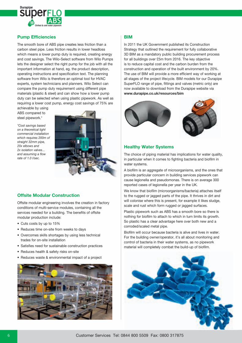
Healthy Water Systems
The choice of piping material has implications for water quality, in particular when it comes to fighting bacteria and biofilm in water systems.
A biofilm is an aggregate of microorganisms, and the ones that provide particular concern in building services pipework can cause legionella and pseudomonas. There is on average 300 reported cases of legionella per year in the UK.
We know that biofilm (microorganisms/bacteria) attaches itself to the rugged or jagged parts of the pipe. It thrives in dirt and will colonise where this is present, for example it likes sludge, scale and rust which form rugged or jagged surfaces.
Plastic pipework such as ABS has a smooth bore so there is nothing for biofilm to attach to which in turn limits its growth. So plastic has a clear advantage here over both new and a corroded/scaled metal pipe.
Biofilm will occur because bacteria is alive and lives in water. For the building owner/operator, it’s all about monitoring and control of bacteria in their water systems, as no pipework material will completely combat the build-up of biofilm.
BIM
In 2011 the UK Government published its Construction Strategy that outlined the requirement for fully collaborative 3D BIM as a mandatory public building procurement process for all buildings over £5m from 2016. The key objective is to reduce capital cost and the carbon burden from the construction and operation of the built environment by 20%. The use of BIM will provide a more efficient way of working at all stages of the project lifecycle. BIM models for our Durapipe SuperFLO range of pipe, fittings and valves (metric only) are now available to download from the Durapipe website via www.durapipe.co.uk/resources/bim
email: [email protected] web: www.durapipe.co.uk 7Customer Services Tel: 0844 800 5509 Fax: 0800 317875
Bui
ldin
g S
ervi
ces
Ove
rvie
w
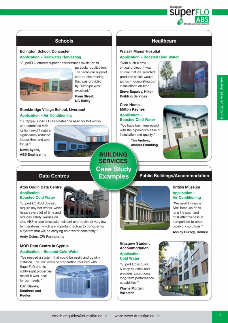
Atos Origin Data CentreApplication – Boosted Cold Water “SuperFLO ABS doesn’t require any hot works, which helps save a lot of time and reduces safety worries on site. ABS is also limescale resistant and ductile at very low temperatures, which are important factors to consider for a system that will be carrying cold water constantly.”
Andy Coles, CW Partnership
Stockbridge Village School, LiverpoolApplication – Air Conditioning “Durapipe SuperFLO eliminates the need for hot works and combined with its lightweight nature, significantly reduced labour time and cost for us.”
Kevin Sykes, A&B Engineering
Edlington School, DoncasterApplication – Rainwater Harvesting“SuperFLO offered superior performance levels for its
particular application. The technical support and on-site training that was provided by Durapipe was excellent.”
Ryan Street, NG Bailey
MOD Data Centre in CyprusApplication – Boosted Cold Water “We needed a system that could be easily and quickly installed. The low levels of preparation required with SuperFLO and its lightweight properties meant it was ideal for our needs.”
Carl Davies, Southern and Redfern
Glasgow Student AccommodationApplication – Cold Water“SuperFLO is quick & easy to install and provides exceptional long-term performance capabilities.”
Wayne Morgan, Vallectric
Walsall Manor HospitalApplication – Boosted Cold Water“With such a time- critical project, it was crucial that we selected products which would aid us in completing our installations on time.”
Steve Baguley, Hilton Building Services
HealthcareSchools
Data Centres Public Buildings/Accommodation
BUILDING SERVICES
Case Study Examples
British MuseumApplication – Air Conditioning “We used Durapipe ABS because of its long life span and cost-effectiveness in comparison to other pipework solutions.”
Ashley Pursey, Romec
Care Home, Milton KeynesApplication – Boosted Cold Water“We have been impressed with the pipework’s ease of installation and quality.”
Tim Anders, Anders Plumbing
email: [email protected] web: www.durapipe.co.ukCustomer Services Tel: 0844 800 5509 Fax: 0800 3178758
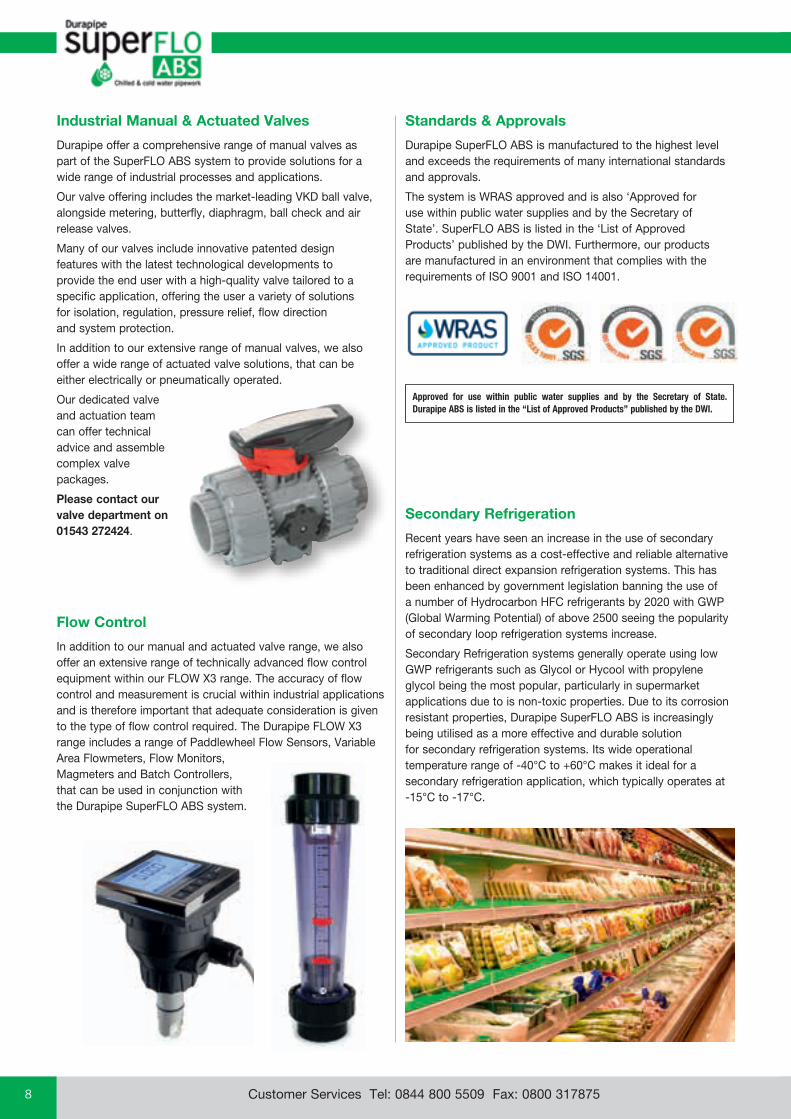
Industrial Manual & Actuated Valves
Durapipe offer a comprehensive range of manual valves as part of the SuperFLO ABS system to provide solutions for a wide range of industrial processes and applications.
Our valve offering includes the market-leading VKD ball valve, alongside metering, butterfly, diaphragm, ball check and air release valves.
Many of our valves include innovative patented design features with the latest technological developments to provide the end user with a high-quality valve tailored to a specific application, offering the user a variety of solutions for isolation, regulation, pressure relief, flow direction and system protection.
In addition to our extensive range of manual valves, we also offer a wide range of actuated valve solutions, that can be either electrically or pneumatically operated.
Our dedicated valve and actuation team can offer technical advice and assemble complex valve packages.
Please contact our valve department on 01543 272424.
Flow Control
In addition to our manual and actuated valve range, we also offer an extensive range of technically advanced flow control equipment within our FLOW X3 range. The accuracy of flow control and measurement is crucial within industrial applications and is therefore important that adequate consideration is given to the type of flow control required. The Durapipe FLOW X3 range includes a range of Paddlewheel Flow Sensors, Variable Area Flowmeters, Flow Monitors, Magmeters and Batch Controllers, that can be used in conjunction with the Durapipe SuperFLO ABS system.
Secondary Refrigeration
Recent years have seen an increase in the use of secondary refrigeration systems as a cost-effective and reliable alternative to traditional direct expansion refrigeration systems. This has been enhanced by government legislation banning the use of a number of Hydrocarbon HFC refrigerants by 2020 with GWP (Global Warming Potential) of above 2500 seeing the popularity of secondary loop refrigeration systems increase.
Secondary Refrigeration systems generally operate using low GWP refrigerants such as Glycol or Hycool with propylene glycol being the most popular, particularly in supermarket applications due to is non-toxic properties. Due to its corrosion resistant properties, Durapipe SuperFLO ABS is increasingly being utilised as a more effective and durable solution for secondary refrigeration systems. Its wide operational temperature range of -40°C to +60°C makes it ideal for a secondary refrigeration application, which typically operates at -15°C to -17°C.
Standards & Approvals
Durapipe SuperFLO ABS is manufactured to the highest level and exceeds the requirements of many international standards and approvals.
The system is WRAS approved and is also ‘Approved for use within public water supplies and by the Secretary of State’. SuperFLO ABS is listed in the ‘List of Approved Products’ published by the DWI. Furthermore, our products are manufactured in an environment that complies with the requirements of ISO 9001 and ISO 14001.
Approved for use within public water supplies and by the Secretary of State. Durapipe ABS is listed in the “List of Approved Products” published by the DWI.
email: [email protected] web: www.durapipe.co.uk 9Customer Services Tel: 0844 800 5509 Fax: 0800 317875
Indu
stri
al O
verv
iew
Marine and Offshore Food & Beverage
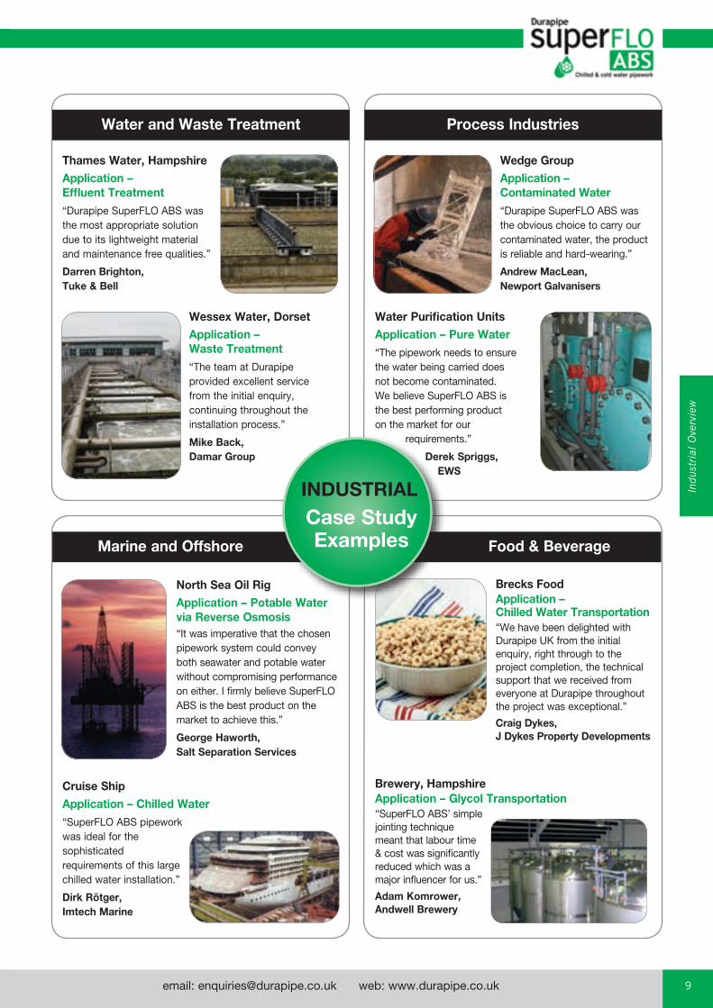
Thames Water, HampshireApplication – Effluent Treatment“Durapipe SuperFLO ABS was the most appropriate solution due to its lightweight material and maintenance free qualities.”
Darren Brighton, Tuke & Bell
Wessex Water, DorsetApplication – Waste Treatment“The team at Durapipe provided excellent service from the initial enquiry, continuing throughout the installation process.”
Mike Back, Damar Group
Wedge GroupApplication – Contaminated Water“Durapipe SuperFLO ABS was the obvious choice to carry our contaminated water, the product is reliable and hard-wearing.”
Andrew MacLean, Newport Galvanisers
Water Purification UnitsApplication – Pure Water“The pipework needs to ensure the water being carried does not become contaminated. We believe SuperFLO ABS is the best performing product on the market for our requirements.”
Derek Spriggs, EWS
Brewery, HampshireApplication – Glycol Transportation “SuperFLO ABS’ simple jointing technique meant that labour time & cost was significantly reduced which was a major influencer for us.”
Adam Komrower, Andwell Brewery
North Sea Oil RigApplication – Potable Water via Reverse Osmosis “It was imperative that the chosen pipework system could convey both seawater and potable water without compromising performance on either. I firmly believe SuperFLO ABS is the best product on the market to achieve this.”
George Haworth, Salt Separation Services
Cruise ShipApplication – Chilled Water“SuperFLO ABS pipework was ideal for the sophisticated requirements of this large chilled water installation.”
Dirk Rötger, Imtech Marine
Process IndustriesWater and Waste Treatment
INDUSTRIALCase Study Examples
Brecks FoodApplication – Chilled Water Transportation“We have been delighted with Durapipe UK from the initial enquiry, right through to the project completion, the technical support that we received from everyone at Durapipe throughout the project was exceptional.”
Craig Dykes, J Dykes Property Developments

email: [email protected] web: www.durapipe.co.ukCustomer Services Tel: 0844 800 5509 Fax: 0800 31787510
Durapipe & AliaxisThe continuous mission of Durapipe and the Aliaxis Group is to ensure our product offering is as sustainable as possible and considers the impacts on the environment whilst maintaining the highest quality and performance.
• Comply with all relevant environmental legislation, codes of practice and standards relating to quality and the environment.
• Continually improve the company’s environmental performance, minimising any pollution risk and adopting best practice.
• Increase usage of recycled materials where appropriate.
• Take positive action to reduce waste by promoting energy conservation and recycling.
• Optimising production processes.
• Consolidating transportation routes across group companies.
Durapipe Environmental Management System
Durapipe UK operates and environmental management system that has been successfully assessed against the BS EN ISO 14001 environmental management system.
SustainabilityIntroduction
Plastic piping systems are a sustainable and environmentally responsible choice that will serve generations to come. They are energy efficient during manufacturing and provide peak performance during service. Strong, durable, lightweight and flexible, plastic piping systems require significantly less energy to manufacture, transport and install than metal alternatives, and supply a long service life.
The cumulative energy requirements to manufacture, install and transport plastic pipework is estimated to be substantially less than most non-plastic systems.
Plastic saves energy – besides the technical advantages of plastics (eg. corrosion resistance) there are inherent benefits that contribute to energy efficiency and energy sustainability. The chain of activity outlined on the opposite page highlights where plastic has a positive impact compared to copper and steel which have a higher energy demand.
email: [email protected] web: www.durapipe.co.uk 11Customer Services Tel: 0844 800 5509 Fax: 0800 317875
Tech
nica
l &
Gen
eral
In
form
atio
n
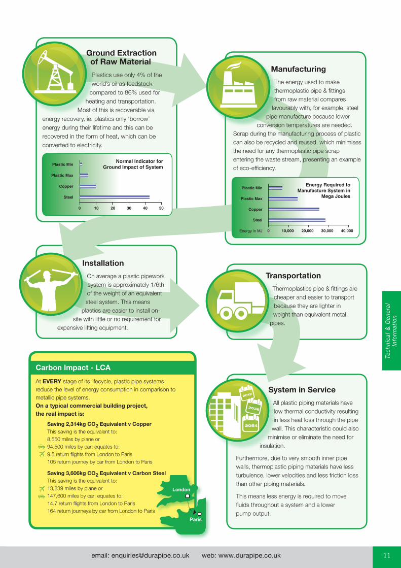
Ground Extraction of Raw Material
Plastics use only 4% of the world’s oil as feedstock
compared to 86% used for heating and transportation.
Most of this is recoverable via energy recovery, ie. plastics only ‘borrow’ energy during their lifetime and this can be recovered in the form of heat, which can be converted to electricity.
Manufacturing
The energy used to make thermoplastic pipe & fittings from raw material compares
favourably with, for example, steel pipe manufacture because lower
conversion temperatures are needed. Scrap during the manufacturing process of plastic can also be recycled and reused, which minimises the need for any thermoplastic pipe scrap entering the waste stream, presenting an example of eco-efficiency.
Installation
On average a plastic pipework system is approximately 1/6th of the weight of an equivalent steel system. This means
plastics are easier to install on-site with little or no requirement for
expensive lifting equipment.
Transportation
Thermoplastics pipe & fittings are cheaper and easier to transport because they are lighter in weight than equivalent metal
pipes.
System in Service
All plastic piping materials have low thermal conductivity resulting in less heat loss through the pipe
wall. This characteristic could also minimise or eliminate the need for
insulation.
Furthermore, due to very smooth inner pipe walls, thermoplastic piping materials have less turbulence, lower velocities and less friction loss than other piping materials.
This means less energy is required to move fluids throughout a system and a lower pump output.
Saving 2,314kg CO2 Equivalent v Copper This saving is the equivalent to: 8,550 miles by plane or 94,500 miles by car; equates to: 9.5 return flights from London to Paris 105 return journey by car from London to Paris
Saving 3,606kg CO2 Equivalent v Carbon Steel This saving is the equivalent to: 13,239 miles by plane or 147,600 miles by car; equates to: 14.7 return flights from London to Paris 164 return journeys by car from London to Paris
London
Paris
Carbon Impact - LCA
At EVERY stage of its lifecycle, plastic pipe systems reduce the level of energy consumption in comparison to metallic pipe systems. On a typical commercial building project, the real impact is:
email: [email protected] web: www.durapipe.co.ukCustomer Services Tel: 0844 800 5509 Fax: 0800 31787512
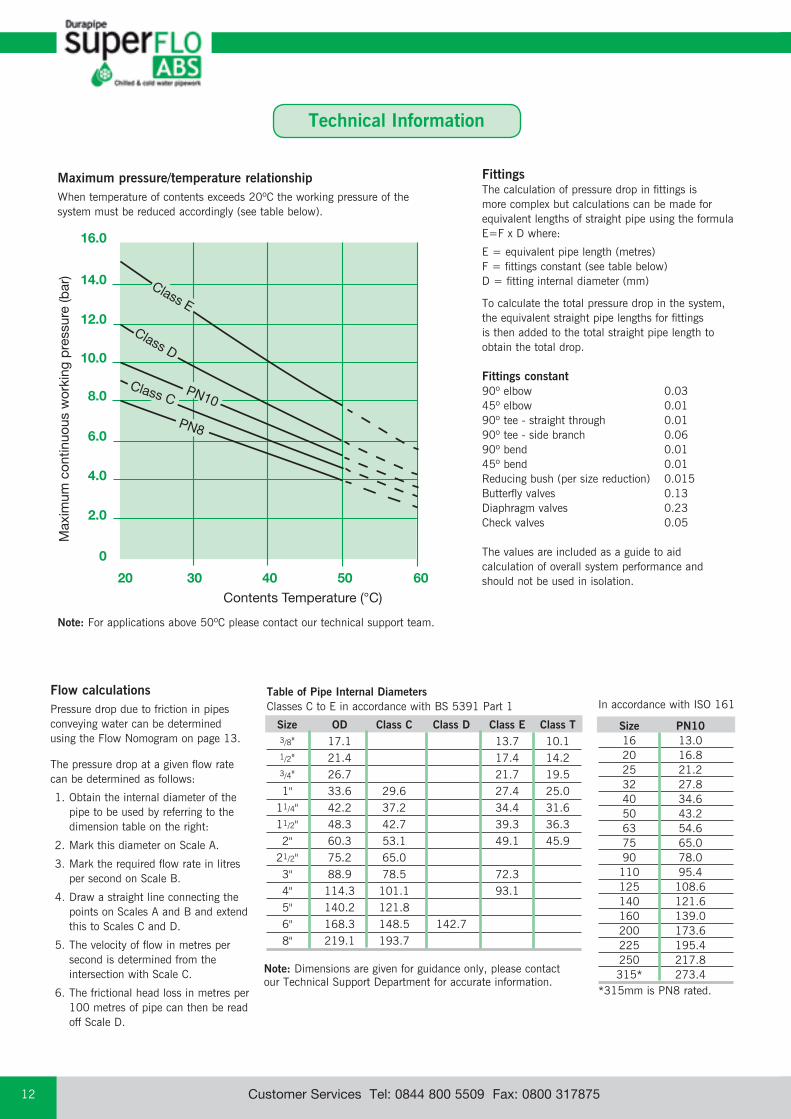
Size OD Class C Class D Class E Class T 3/8" 17.1 13.7 10.1 1/2" 21.4 17.4 14.2 3/4" 26.7 21.7 19.5 1" 33.6 29.6 27.4 25.0 11/4" 42.2 37.2 34.4 31.6 11/2" 48.3 42.7 39.3 36.3 2" 60.3 53.1 49.1 45.9 21/2" 75.2 65.0 3" 88.9 78.5 72.3 4" 114.3 101.1 93.1 5" 140.2 121.8 6" 168.3 148.5 142.7 8" 219.1 193.7
Table of Pipe Internal DiametersClasses C to E in accordance with BS 5391 Part 1
Size PN10 16 13.0 20 16.8 25 21.2 32 27.8 40 34.6 50 43.2 63 54.6 75 65.0 90 78.0 110 95.4 125 108.6 140 121.6 160 139.0 200 173.6 225 195.4 250 217.8 315* 273.4*315mm is PN8 rated.
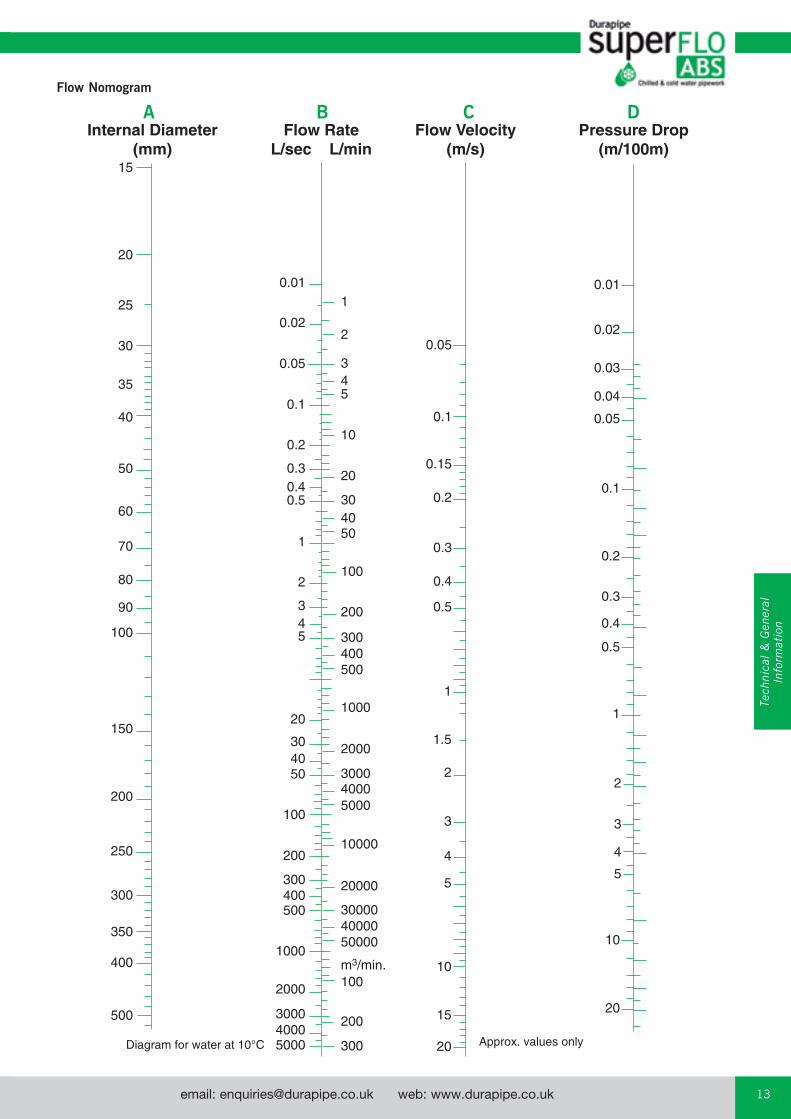
In accordance with ISO 161Flow calculations Pressure drop due to friction in pipes conveying water can be determined using the Flow Nomogram on page 13.
The pressure drop at a given flow rate can be determined as follows:
1. Obtain the internal diameter of the pipe to be used by referring to the dimension table on the right:
2. Mark this diameter on Scale A.
3. Mark the required flow rate in litres per second on Scale B.
4. Draw a straight line connecting the points on Scales A and B and extend this to Scales C and D.
5. The velocity of flow in metres per second is determined from the intersection with Scale C.
6. The frictional head loss in metres per 100 metres of pipe can then be read off Scale D.
Technical Information
Note: For applications above 50ºC please contact our technical support team.
0
20 30 40 50 60
2.0
4.0
6.0
8.0
10.0
12.0
14.0
16.0
Contents Temperature (°C)
Max
imum
con
tinuo
us w
orki
ng p
ress
ure
(bar
)
PN8
Class D
Class E
Class CPN10
Maximum pressure/temperature relationship When temperature of contents exceeds 20ºC the working pressure of the system must be reduced accordingly (see table below).
Fittings The calculation of pressure drop in fittings is more complex but calculations can be made for equivalent lengths of straight pipe using the formula E=F x D where:
E = equivalent pipe length (metres)F = fittings constant (see table below)D = fitting internal diameter (mm)
To calculate the total pressure drop in the system, the equivalent straight pipe lengths for fittings is then added to the total straight pipe length to obtain the total drop.
Fittings constant90º elbow 0.0345º elbow 0.0190º tee - straight through 0.0190º tee - side branch 0.0690º bend 0.0145º bend 0.01Reducing bush (per size reduction) 0.015Butterfly valves 0.13Diaphragm valves 0.23Check valves 0.05
The values are included as a guide to aid calculation of overall system performance and should not be used in isolation.
Note: Dimensions are given for guidance only, please contact our Technical Support Department for accurate information.
email: [email protected] web: www.durapipe.co.uk 13Customer Services Tel: 0844 800 5509 Fax: 0800 317875
Flow Nomogram
0.01
0.02
0.05
0.1
0.2
0.30.40.5
1
2
345
20
304050
100
200
300400500
1000
2000
300040005000 300
200
100
500004000030000
20000
10000
500040003000
2000
1000
500400300
200
100
504030
20
10
543
2
1
m3/min.
0.05
0.1
0.15
0.2
0.3
0.4
0.5
1
1.5
2
3
4
5
10
15
20
0.01
0.02
0.03
0.04
0.05
0.1
0.2
0.3
0.4
0.5
1
2
3
4
5
10
20
Pressure Drop(m/100m)
Flow Velocity(m/s)
Flow RateL/sec L/min
Internal Diameter(mm)
15
20
30
40
50
60
70
80
90
100
150
200
250
300
350
400
500
25
35
A B C D
Tech
nica
l &
Gen
eral
In
form
atio
n

email: [email protected] web: www.durapipe.co.ukCustomer Services Tel: 0844 800 5509 Fax: 0800 31787514
SuperFLO ABS Jointing GuideSolvent cement welding offers a simple and quick means of constructing high integrity, leak-free joints.
The solvent cement operates by chemically softening the joint surfaces. Joint integrity will be greatly reduced if these surfaces are not clean and properly prepared.
Durapipe SuperFLO ABS solvent cement must be used. The jointing procedure detailed below must be followed.
When using ‘One-step’ solvent cement, it is not necessary to abrade pipe or fitting (unless making a joint on to old ABS pipe).
No attempt should be made to increase the clearance between the pipes and fittings.
Procedure1. The pipe must be cut clean and square. A suitable wheel cutter
will eliminate swarf. As an alternative (and on larger sizes) a carpenters saw should be used, however this may create dust and swarf which can enter the system.
2. Chamfer the end of the pipe using a coarse file or suitable chamfering tool. The chamfer should be approximately 45° by 3mm to 5mm depending on the pipe size. Reducing bushes should also be chamfered (unless where a moulded chamfer is included).
3. Mark the pipe a known distance from the end and clear of the area to be cleaned. This mark should be used to confirm full insertion of pipe into socket of fitting.
4. Ensure joint surfaces are clean and free from moisture. Clean surfaces thoroughly with Durapipe Eco-cleaner using lint
free cloth/paper towel.
5. Using a clean brush apply cement to the pipe and fitting. The joint surfaces should be completely covered by cement.
Cement should be applied using an appropriate size brush and tin of cement. It is important to apply cement quickly to enable assembly without excessive force being required.
When applying cement with brush, the size of the brush should be approximately half the size of the pipe to be jointed - brush size up to 21/2" (63mm) for 0.5 litre and up to 3" (75mm) for 1 litre tins.
6. Immediately after applications of cement, push pipe fully home into the fitting. Do not twist. Hold the pipe and the fitting for times varying from a few seconds on sizes 3/8" or 16mm up to 1 minute on size 315mm. The slight taper moulded into the fitting may otherwise cause it to slide off the pipe with consequent loss of joint strength. Application of the correct amount of cement will result in a neat bead of cement at the edge of the fitting and at the edge of the pipe. Excessive deposits inside the fittings must be avoided as these can weaken the wall, particularly on smaller sizes. When working under cold conditions make sure the joints are free from frost and moisture.
email: [email protected] web: www.durapipe.co.uk 15Customer Services Tel: 0844 800 5509 Fax: 0800 317875
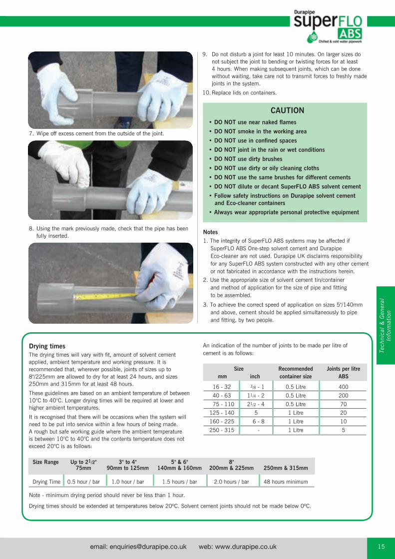
7. Wipe off excess cement from the outside of the joint.
8. Using the mark previously made, check that the pipe has been fully inserted.
CAUTION• DO NOT use near naked flames
• DO NOT smoke in the working area
• DO NOT use in confined spaces
• DO NOT joint in the rain or wet conditions
• DO NOT use dirty brushes
• DO NOT use dirty or oily cleaning cloths
• DO NOT use the same brushes for different cements
• DO NOT dilute or decant SuperFLO ABS solvent cement
• Follow safety instructions on Durapipe solvent cement and Eco-cleaner containers
• Always wear appropriate personal protective equipment
Notes1. The integrity of SuperFLO ABS systems may be affected if
SuperFLO ABS One-step solvent cement and Durapipe Eco-cleaner are not used. Durapipe UK disclaims responsibility for any SuperFLO ABS system constructed with any other cement or not fabricated in accordance with the instructions herein.
2. Use the appropriate size of solvent cement tin/container and method of application for the size of pipe and fitting to be assembled.
3. To achieve the correct speed of application on sizes 5"/140mm and above, cement should be applied simultaneously to pipe and fitting, by two people.
Note - minimum drying period should never be less than 1 hour.
Drying times should be extended at temperatures below 20ºC. Solvent cement joints should not be made below 0ºC.
Size Range Up to 21/2" 3" to 4" 5" & 6" 8" 75mm 90mm to 125mm 140mm & 160mm 200mm & 225mm 250mm & 315mm
Drying Time 0.5 hour / bar 1.0 hour / bar 1.5 hours / bar 2.0 hours / bar 48 hours minimum
Drying timesThe drying times will vary with fit, amount of solvent cement applied, ambient temperature and working pressure. It is recommended that, wherever possible, joints of sizes up to 8"/225mm are allowed to dry for at least 24 hours, and sizes 250mm and 315mm for at least 48 hours.
These guidelines are based on an ambient temperature of between 10°C to 40°C. Longer drying times will be required at lower and higher ambient temperatures.
It is recognised that there will be occasions when the system will need to be put into service within a few hours of being made. A rough but safe working guide where the ambient temperature is between 10°C to 40°C and the contents temperature does not exceed 20°C is as follows:
Size Recommended Joints per litre mm inch container size ABS
16 - 32 3/8 - 1 0.5 Litre 400
40 - 63 11/4 - 2 0.5 Litre 200
75 - 110 21/2 - 4 0.5 Litre 70
125 - 140 5 1 Litre 20
160 - 225 6 - 8 1 Litre 10
250 - 315 - 1 Litre 5
An indication of the number of joints to be made per litre of cement is as follows:
9. Do not disturb a joint for least 10 minutes. On larger sizes do not subject the joint to bending or twisting forces for at least 4 hours. When making subsequent joints, which can be done without waiting, take care not to transmit forces to freshly made joints in the system.
10. Replace lids on containers.
Tech
nica
l &
Gen
eral
In
form
atio
n
email: [email protected] web: www.durapipe.co.ukCustomer Services Tel: 0844 800 5509 Fax: 0800 31787516
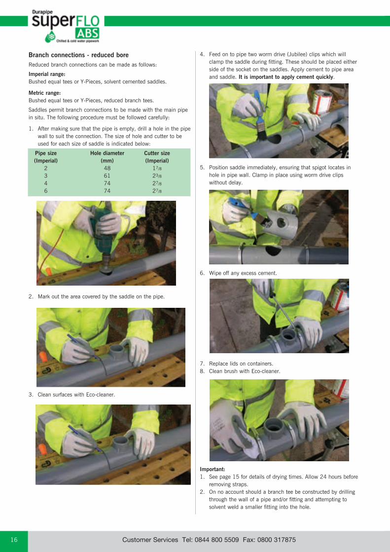
Branch connections - reduced boreReduced branch connections can be made as follows:
Imperial range:Bushed equal tees or Y-Pieces, solvent cemented saddles.
Metric range:Bushed equal tees or Y-Pieces, reduced branch tees.
Saddles permit branch connections to be made with the main pipe in situ. The following procedure must be followed carefully:
1. After making sure that the pipe is empty, drill a hole in the pipe wall to suit the connection. The size of hole and cutter to be used for each size of saddle is indicated below:
Pipe size Hole diameter Cutter size (Imperial) (mm) (Imperial) 2 48 17/8
3 61 23/8
4 74 27/8
6 74 27/8
2. Mark out the area covered by the saddle on the pipe.
3. Clean surfaces with Eco-cleaner.
4. Feed on to pipe two worm drive (Jubilee) clips which will clamp the saddle during fitting. These should be placed either side of the socket on the saddles. Apply cement to pipe area and saddle. It is important to apply cement quickly.
5. Position saddle immediately, ensuring that spigot locates in hole in pipe wall. Clamp in place using worm drive clips without delay.
6. Wipe off any excess cement.
7. Replace lids on containers. 8. Clean brush with Eco-cleaner.
Important:1. See page 15 for details of drying times. Allow 24 hours before
removing straps.2. On no account should a branch tee be constructed by drilling
through the wall of a pipe and/or fitting and attempting to solvent weld a smaller fitting into the hole.
email: [email protected] web: www.durapipe.co.uk 17Customer Services Tel: 0844 800 5509 Fax: 0800 317875
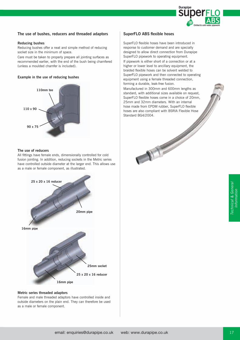
Reducing bushes Reducing bushes offer a neat and simple method of reducing socket size in the minimum of space.Care must be taken to properly prepare all jointing surfaces as recommended earlier, with the end of the bush being chamfered (unless a moulded chamfer is included).
Example in the use of reducing bushes
The use of reducersAll fittings have female ends, dimensionally controlled for cold fusion jointing. In addition, reducing sockets in the Metric series have controlled outside diameter at the larger end. This allows use as a male or female component, as illustrated.
Metric series threaded adaptorsFemale and male threaded adaptors have controlled inside and outside diameters on the plain end. They can therefore be used as a male or female component.
The use of bushes, reducers and threaded adaptors
25 x 20 x 16 reducer
16mm pipe
20mm pipe
110mm tee
90 x 75
110 x 90
25mm socket
25 x 20 x 16 reducer
16mm pipe
Tech
nica
l &
Gen
eral
In
form
atio
n
SuperFLO ABS flexible hoses
SuperFLO flexible hoses have been introduced in response to customer demand and are specially designed to allow direct connection from Durapipe SuperFLO pipework to operating equipment.If pipework is either short of a connection or at a higher or lower level to ancillary equipment, the braided flexible hoses can be solvent welded to SuperFLO pipework and then connected to operating equipment using a female threaded connection, forming a durable, leak-free fusion.Manufactured in 300mm and 600mm lengths as standard, with additional sizes available on request, SuperFLO flexible hoses come in a choice of 20mm, 25mm and 32mm diameters. With an internal hose made from EPDM rubber, SuperFLO flexible hoses are also compliant with BSRIA Flexible Hose Standard BG4/2004.
email: [email protected] web: www.durapipe.co.ukCustomer Services Tel: 0844 800 5509 Fax: 0800 31787518
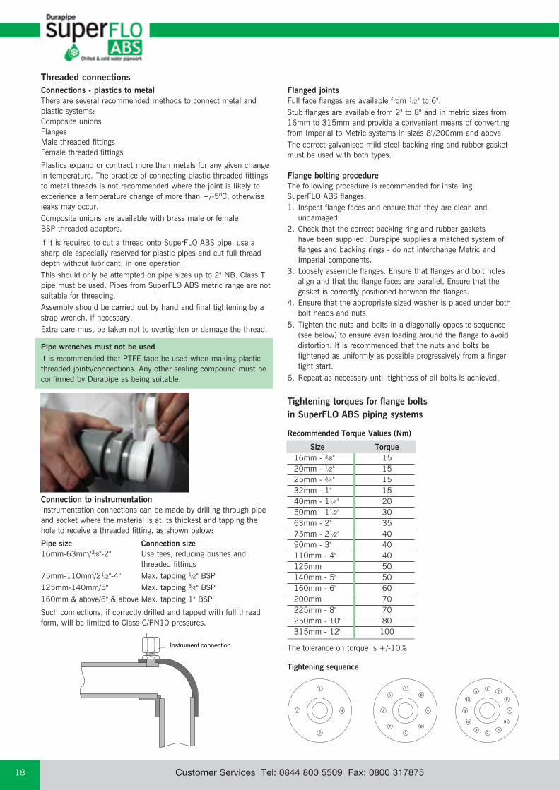
Instrument connection
Flanged jointsFull face flanges are available from 1/2" to 6".Stub flanges are available from 2" to 8" and in metric sizes from 16mm to 315mm and provide a convenient means of converting from Imperial to Metric systems in sizes 8"/200mm and above.The correct galvanised mild steel backing ring and rubber gasket must be used with both types.
Flange bolting procedureThe following procedure is recommended for installing SuperFLO ABS flanges:1. Inspect flange faces and ensure that they are clean and
undamaged.2. Check that the correct backing ring and rubber gaskets
have been supplied. Durapipe supplies a matched system of flanges and backing rings - do not interchange Metric and Imperial components.
3. Loosely assemble flanges. Ensure that flanges and bolt holes align and that the flange faces are parallel. Ensure that the gasket is correctly positioned between the flanges.
4. Ensure that the appropriate sized washer is placed under both bolt heads and nuts.
5. Tighten the nuts and bolts in a diagonally opposite sequence (see below) to ensure even loading around the flange to avoid distortion. It is recommended that the nuts and bolts be tightened as uniformly as possible progressively from a finger tight start.
6. Repeat as necessary until tightness of all bolts is achieved.
Connections - plastics to metal There are several recommended methods to connect metal and plastic systems:Composite unionsFlangesMale threaded fittingsFemale threaded fittings
Plastics expand or contract more than metals for any given change in temperature. The practice of connecting plastic threaded fittings to metal threads is not recommended where the joint is likely to experience a temperature change of more than +/-5ºC, otherwise leaks may occur.Composite unions are available with brass male or female BSP threaded adaptors.
Tightening torques for flange bolts in SuperFLO ABS piping systems
Recommended Torque Values (Nm)
The tolerance on torque is +/-10%
Size Torque16mm - 3⁄8" 1520mm - 1⁄2" 1525mm - 3⁄4" 1532mm - 1" 1540mm - 11⁄4" 2050mm - 11⁄2" 3063mm - 2" 3575mm - 21⁄2" 4090mm - 3" 40110mm - 4" 40125mm 50140mm - 5" 50160mm - 6" 60200mm 70225mm - 8" 70250mm - 10" 80315mm - 12" 100
Tightening sequence
If it is required to cut a thread onto SuperFLO ABS pipe, use a sharp die especially reserved for plastic pipes and cut full thread depth without lubricant, in one operation.This should only be attempted on pipe sizes up to 2" NB. Class T pipe must be used. Pipes from SuperFLO ABS metric range are not suitable for threading.Assembly should be carried out by hand and final tightening by a strap wrench, if necessary.Extra care must be taken not to overtighten or damage the thread.
Pipe wrenches must not be usedIt is recommended that PTFE tape be used when making plastic threaded joints/connections. Any other sealing compound must be confirmed by Durapipe as being suitable.
Threaded connections
1
2
3 4
5
67
8
1
2
3 4
5
6
7
8
11
912
10
1
2
3 4
Connection to instrumentationInstrumentation connections can be made by drilling through pipe and socket where the material is at its thickest and tapping the hole to receive a threaded fitting, as shown below:
Pipe size Connection size16mm-63mm/3⁄8"-2" Use tees, reducing bushes and threaded fittings75mm-110mm/21⁄2"-4" Max. tapping 1⁄2" BSP125mm-140mm/5" Max. tapping 3⁄4" BSP160mm & above/6" & above Max. tapping 1" BSP
Such connections, if correctly drilled and tapped with full thread form, will be limited to Class C/PN10 pressures.
email: [email protected] web: www.durapipe.co.uk 19Customer Services Tel: 0844 800 5509 Fax: 0800 317875
Calculating expansion and contractionTemperature variations in a pipework system will increase or decrease the length of each pipe. This is the result of temperature changes in the fluid carried and also from ambient temperature variations. The rate of expansion or contraction of pipework is dependent on its length, its coefficient of expansion and the temperature difference.Increase/decrease in pipe length is given by the formula:
Expansion = L x α x ΔT
where: L = length (mm) α = coefficient of linear expansion ΔT = temperature difference of the pipe (ºC)
The coefficient of linear expansion for SuperFLO ABS: 10 x 10-5 per ºC
Rule of thumb: ABS expands/contracts 1mm/metre/10ºC temperature change:
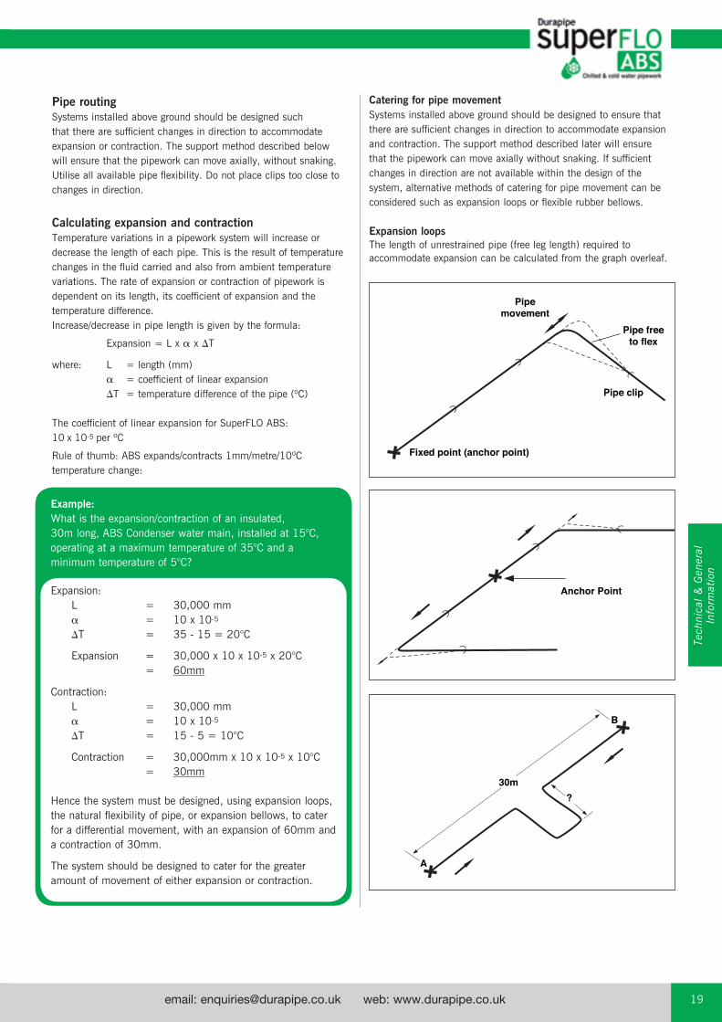
Pipemovement
Fixed point (anchor point)
Pipe clip
Pipe freeto flex
Anchor Point
A
B
?30m
Pipe routingSystems installed above ground should be designed such that there are sufficient changes in direction to accommodate expansion or contraction. The support method described below will ensure that the pipework can move axially, without snaking. Utilise all available pipe flexibility. Do not place clips too close to changes in direction.
Catering for pipe movementSystems installed above ground should be designed to ensure that there are sufficient changes in direction to accommodate expansion and contraction. The support method described later will ensure that the pipework can move axially without snaking. If sufficient changes in direction are not available within the design of the system, alternative methods of catering for pipe movement can be considered such as expansion loops or flexible rubber bellows.
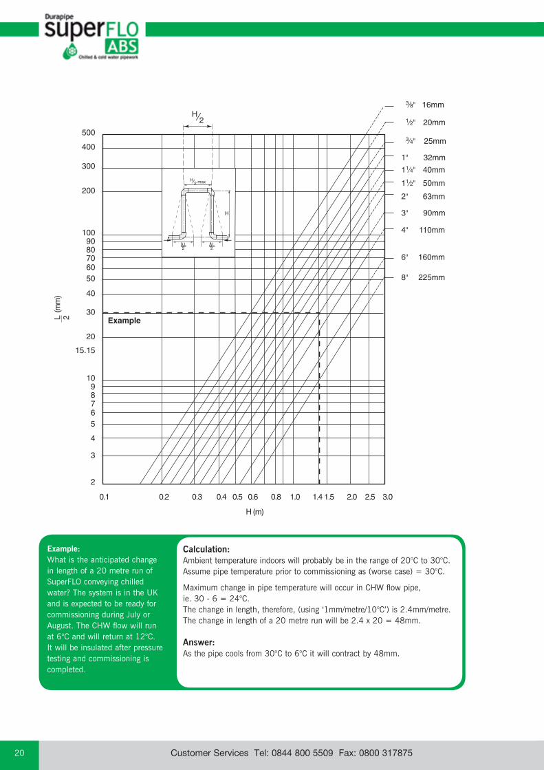
Expansion loopsThe length of unrestrained pipe (free leg length) required to accommodate expansion can be calculated from the graph overleaf.
Example:What is the expansion/contraction of an insulated, 30m long, ABS Condenser water main, installed at 15°C, operating at a maximum temperature of 35°C and a minimum temperature of 5°C?
Expansion: L = 30,000 mm α = 10 x 10-5
ΔT = 35 - 15 = 20°C
Expansion = 30,000 x 10 x 10-5 x 20°C = 60mm
Contraction: L = 30,000 mm α = 10 x 10-5
ΔT = 15 - 5 = 10°C
Contraction = 30,000mm x 10 x 10-5 x 10°C = 30mm
Hence the system must be designed, using expansion loops, the natural flexibility of pipe, or expansion bellows, to cater for a differential movement, with an expansion of 60mm and a contraction of 30mm.
The system should be designed to cater for the greater amount of movement of either expansion or contraction.
Tech
nica
l &
Gen
eral
In
form
atio
n
email: [email protected] web: www.durapipe.co.ukCustomer Services Tel: 0844 800 5509 Fax: 0800 31787520
L2
H
H⁄2 max
L2
Example:What is the anticipated change in length of a 20 metre run of SuperFLO conveying chilled water? The system is in the UK and is expected to be ready for commissioning during July or August. The CHW flow will run at 6°C and will return at 12°C. It will be insulated after pressure testing and commissioning is completed.
Calculation:Ambient temperature indoors will probably be in the range of 20°C to 30°C. Assume pipe temperature prior to commissioning as (worse case) = 30°C.
Maximum change in pipe temperature will occur in CHW flow pipe, ie. 30 - 6 = 24°C.The change in length, therefore, (using ‘1mm/metre/10°C’) is 2.4mm/metre.The change in length of a 20 metre run will be 2.4 x 20 = 48mm.
Answer:As the pipe cools from 30°C to 6°C it will contract by 48mm.
email: [email protected] web: www.durapipe.co.uk 21Customer Services Tel: 0844 800 5509 Fax: 0800 317875
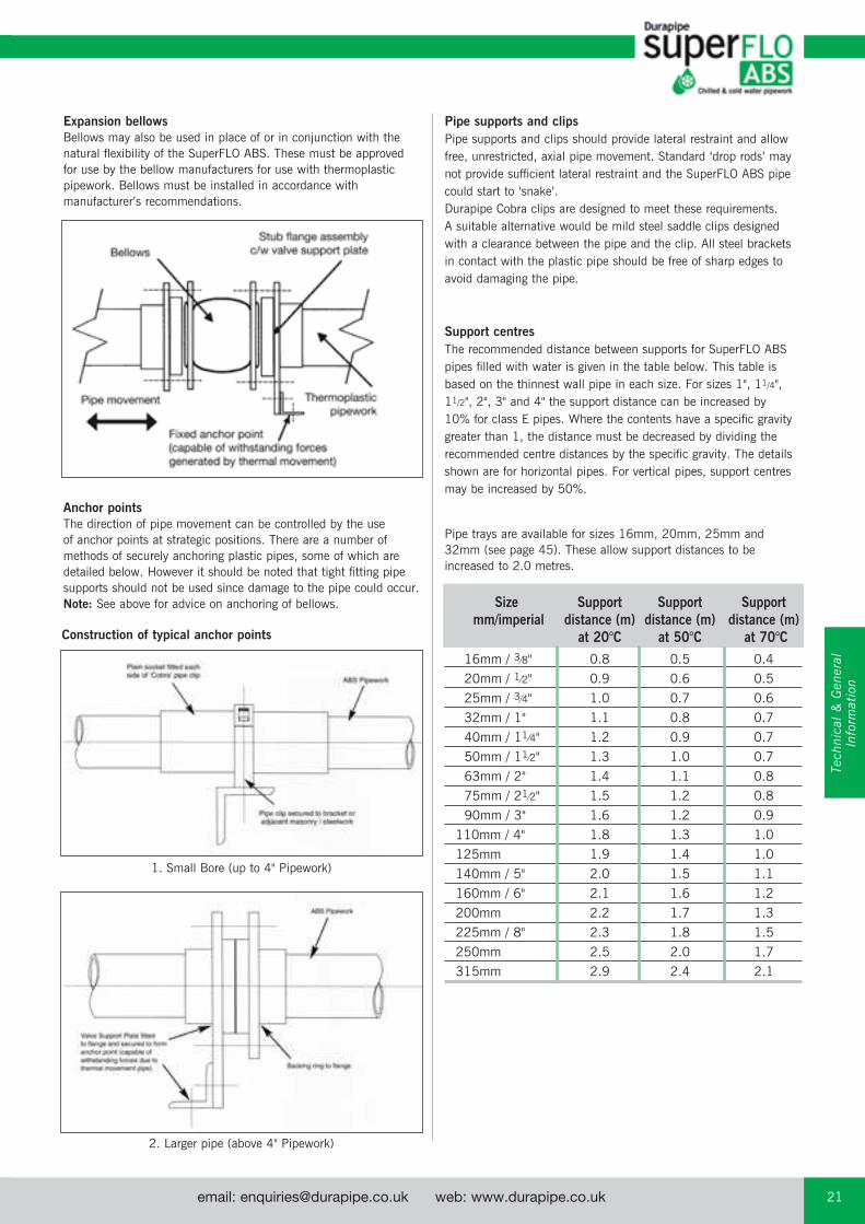
Expansion bellowsBellows may also be used in place of or in conjunction with the natural flexibility of the SuperFLO ABS. These must be approved for use by the bellow manufacturers for use with thermoplastic pipework. Bellows must be installed in accordance with manufacturer’s recommendations.
Pipe supports and clipsPipe supports and clips should provide lateral restraint and allow free, unrestricted, axial pipe movement. Standard ‘drop rods’ may not provide sufficient lateral restraint and the SuperFLO ABS pipe could start to ‘snake’. Durapipe Cobra clips are designed to meet these requirements. A suitable alternative would be mild steel saddle clips designed with a clearance between the pipe and the clip. All steel brackets in contact with the plastic pipe should be free of sharp edges to avoid damaging the pipe.
Size Support Support Support mm/imperial distance (m) distance (m) distance (m) at 20°C at 50°C at 70°C 16mm / 3⁄8" 0.8 0.5 0.4 20mm / 1⁄2" 0.9 0.6 0.5 25mm / 3⁄4" 1.0 0.7 0.6 32mm / 1" 1.1 0.8 0.7 40mm / 11⁄4" 1.2 0.9 0.7 50mm / 11⁄2" 1.3 1.0 0.7 63mm / 2" 1.4 1.1 0.8 75mm / 21⁄2" 1.5 1.2 0.8 90mm / 3" 1.6 1.2 0.9 110mm / 4" 1.8 1.3 1.0 125mm 1.9 1.4 1.0 140mm / 5" 2.0 1.5 1.1 160mm / 6" 2.1 1.6 1.2 200mm 2.2 1.7 1.3 225mm / 8" 2.3 1.8 1.5 250mm 2.5 2.0 1.7 315mm 2.9 2.4 2.1
Support centresThe recommended distance between supports for SuperFLO ABS pipes filled with water is given in the table below. This table is based on the thinnest wall pipe in each size. For sizes 1", 11/4", 11/2", 2", 3" and 4" the support distance can be increased by 10% for class E pipes. Where the contents have a specific gravity greater than 1, the distance must be decreased by dividing the recommended centre distances by the specific gravity. The details shown are for horizontal pipes. For vertical pipes, support centres may be increased by 50%.
Pipe trays are available for sizes 16mm, 20mm, 25mm and 32mm (see page 45). These allow support distances to be increased to 2.0 metres.
Anchor pointsThe direction of pipe movement can be controlled by the use of anchor points at strategic positions. There are a number of methods of securely anchoring plastic pipes, some of which are detailed below. However it should be noted that tight fitting pipe supports should not be used since damage to the pipe could occur. Note: See above for advice on anchoring of bellows.
Construction of typical anchor points
1. Small Bore (up to 4" Pipework)
2. Larger pipe (above 4" Pipework)
Tech
nica
l &
Gen
eral
In
form
atio
n
email: [email protected] web: www.durapipe.co.ukCustomer Services Tel: 0844 800 5509 Fax: 0800 31787522
Anchor blocksFor wholly solvent welded systems the pipework is pressure balanced and anchor thrust blocks are not required.
When rubber ring joints are used it is necessary to provide concrete anchor blocks at all sudden changes in direction such as elbows, bends, tees etc. This is necessary to withstand the forces generated by system pressurisation.
For greater detail, users in the UK are recommended to study the Code of Practice CP 312 published by the Pipe and Fittings Group of the British Standards Institute covering installations above and below ground.
Buried pipesRecommendations covering essential requirements for installations below ground may be summarised as follows:
In general, trenches should not be less than a metre deep. Trenches should be straight sided, approximately 300mm wider than the pipe diameter to allow proper consolidation of packing materials.
Trench bottoms should be as level as is practical.
Large pieces of rock, debris and sharp objects should be removed.
Alternatively gravel can be laid approximately 100mm deep on the floor of the trench. (Sand may be used but subterranean water is liable to wash sand away and leave the pipe unsupported.)
If pipes are jointed above ground, they should remain undisturbed for 2 hours before being lowered into the trench.
After laying, pipes should be covered with gravel or similar material to a depth of 100mm above the crown of the pipe. The gravel should be extended sideways to both trench walls and compacted. This should be done prior to testing, with joints left exposed.
Care should be taken to ensure that sharp objects, stones, etc, are prevented from falling into the trench before covering the pipe.
After pressure testing, joints should be covered with gravel or similar material, and back filling completed.
A section of pipe installed below ground to the above recommendations is shown in the illustration.
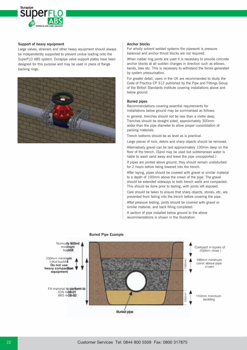
Support of heavy equipmentLarge valves, strainers and other heavy equipment should always be independently supported to prevent undue loading onto the SuperFLO ABS system. Durapipe valve support plates have been designed for this purpose and may be used in place of flange backing rings.
Buried Pipe Example
email: [email protected] web: www.durapipe.co.uk 23Customer Services Tel: 0844 800 5509 Fax: 0800 317875
Thermal insulationSome insulation products can contain substances capable of having a detrimental effect on thermoplastic pipework eg. certain types of foam rubber insulations can cause pipes to fail where the SuperFLO ABS is conveying liquids at temperatures above 30°C.
Recommended insulation - a list of some of the common types of insulation materials known to be suitable with SuperFLO ABS pipework are as follows:Fibre wool, such as ‘Rockwool’Armaflex Class 1 HTKoolphen K Phenolic foamPolystyreneNote - the above list is not exhaustive – please contact our Technical Support Department if further assistance is required.
Some adhesives can also be detrimental. Do not bond insulation to SuperFLO ABS. (This comment also applies to any tapes, adhesives, or other substances used to secure the heating tape to the pipework.)
Trace heating tapesThe selection of heating tapes with silicone rubber, woven wire or woven polyester outer sheaths will eliminate the risk of plasticiser migration. These tapes are therefore preferred for use on thermoplastic systems.
Flexible hosesDurapipe SuperFLO ABS flexible hoses are completely compatible with the full system. However other flexible hoses are known to contain plasticisers such as phthalates which can be harmful to ABS. Please contact our Technical Support Department if further advice is required.
Pipe contents identificationDo not put self-adhesive labels directly on to pipe surfaces as this may be detrimental to pipe performance. It is recommended that some sort of barrier, such as aluminium foil, is placed between pipe and identification label.
Intumescent mastic and mastic sealantsCertain mastic sealants are formulated with phthalates. Phthalates are known to be extremely aggressive toward SuperFLO ABS materials, and therefore confirmation of the suitability of any mastic sealant should be determined before being used in conjunction with SuperFLO ABS pipework.
Pipe clipsIt is important that the composition of pipe clips and their linings do not include substances which might have a detrimental effect upon the SuperFLO ABS pipe. Please check for suitability before use. We strongly recommend the use of Durapipe Cobra clips for pipe sizes up to and including 160mm OD / 6"NB, wherever circumstances allow.
Pneumatic testingPneumatic testing is not recommended because of the risk topersonnel or property if, for example, a joint has beentemporarily assembled without solvent cement and has thenbeen mistakenly left in that condition. Such joints could separatesuddenly and violently during the test.
Also, leak detection sprays designed to detect air leaks on steelpipework can damage thermoplastics.
Contact with synthetic oilsSome synthetic oils are unsuitable for use with thermoplastic pipe systems. The main types of synthetic oils identified as being incompatible with thermoplastic pipe systems includes Esters, Polyalkylene Glycols and Organic Phosphates.
Freezing conditionsPrecautions should be taken to prevent contents freezing, as this can cause pipework to split.
Mono-ethylene glycol can be added to the system to lower the freezing point. See opposite for advice on insulation and trace heating.
Contact with fluxesSome fluxes can be detrimental to SuperFLO ABS. Care should be taken when soldering copper pipework directly above, or close to, SuperFLO ABS pipework.
Buried pipesDo not lay SuperFLO ABS in contaminated ground eg. ‘brown-field’ sites. Do not lay SuperFLO ABS in ground where spillages of chemicals may occur.
Thread sealantsSome thread sealants can damage SuperFLO ABS. PTFE tape should be used when making threaded connections. See page 18 for further information.
Resistance to UV (sunlight)Care should be taken to avoid exposure to UV light, eg. sunlight, particularly during storage. This will cause discoloration and deterioration of the SuperFLO ABS material. Whilst this is a surface effect only it is recommended that precautions be taken to prevent this happening. If stored outdoors pipe should be covered with opaque sheeting. If installed outdoors it can be protected from the effects of UV by insulating or painting.
Pressure surgesDurapipe SuperFLO ABS pipework can withstand pressure surges within the limitations detailed within CP312 Part 2:1973 and its amendment dated 1977.
On no account should pressure surges be allowed to exceed the maximum continuous working pressure calculated using the graph on page 12.
Additional Important Information
Tech
nica
l &
Gen
eral
In
form
atio
n
email: [email protected] web: www.durapipe.co.ukCustomer Services Tel: 0844 800 5509 Fax: 0800 31787524
Chemical resistance Typical Unsuitable for the Sizes and jointing and performance data applications following uses information
Moderately strong mineral acids Chilled water Applications over 60ºC Metric: 16mm to 315mm OD
Caustic and ammoniacal solutions Low temperature brine Bleaches Imperial: 3/8" to 8" NB
Most inorganic salt solutions Potable water Solvents Jointed by solvent cement welding
Some detergents Process water Domestic hot water Threaded fittings available
Temperature range -40ºC to +60ºC Flammable substances
Properties guide
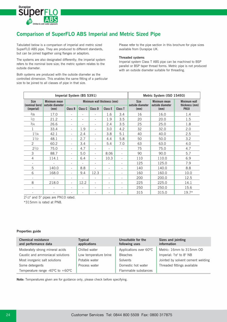
Tabulated below is a comparison of imperial and metric sized SuperFLO ABS pipe. They are produced to different standards, but can be joined together using flanges or adaptors.
The systems are also designated differently; the imperial system refers to the nominal bore size; the metric system relates to the outside diameter.
Both systems are produced with the outside diameter as the controlled dimension. This enables the same fitting of a particular size to be joined to all classes of pipe in that size.
Please refer to the pipe section in this brochure for pipe sizes available from Durapipe UK.
Threaded systems Imperial system Class T ABS pipe can be machined to BSP parallel or BSP taper thread forms. Metric pipe is not produced with an outside diameter suitable for threading.
Comparison of SuperFLO ABS Imperial and Metric Sized Pipe
3/8 17.0 - - - 1.6 3.4 16 16.0 1.4 1/2 21.2 - - - 1.9 3.5 20 20.0 1.5 3/4 26.6 - - - 2.4 3.5 25 25.0 1.8 1 33.4 - 1.9 - 3.0 4.2 32 32.0 2.0 11/4 42.1 - 2.4 - 3.8 5.1 40 40.0 2.5 11/2 48.1 - 2.7 - 4.4 5.8 50 50.0 3.2 2 60.2 - 3.4 - 5.4 7.0 63 63.0 4.0 21/2 75.0 - 4.7 - - - 75 75.0 4.7 3 88.7 - 5.0 - 8.06 - 90 90.0 5.7 4 114.1 - 6.4 - 10.3 - 110 110.0 6.9 - - - - - - - 125 125.0 7.9 5 140.0 - 8.8 - - - 140 140.0 8.8 6 168.0 - 9.4 12.3 - - 160 160.0 10.0 - - - - - - - 200 200.0 12.5 8 218.0 - 12.2 - - - 225 225.0 14.1 - - - - - - - 250 250.0 15.6 - - - - - - - 315 315.0 19.7*21/2" and 5" pipes are PN10 rated.*315mm is rated at PN8.
Size Minimum mean Minimum wall thickness (mm) Size Minimum mean Minimum wall (nominal bore) outside diameter outside diameter outside diameter thickness (mm) (imperial) (mm) Class B Class C Class D Class E Class T (mm) (mm) PN10
Imperial System (BS 5391) Metric System (ISO 15493)
Note: Temperatures given are for guidance only, please check before specifying.
email: [email protected] web: www.durapipe.co.uk 25Customer Services Tel: 0844 800 5509 Fax: 0800 317875
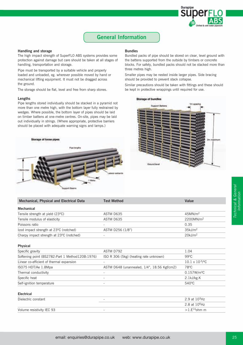
Handling and storageThe high impact strength of SuperFLO ABS systems provides some protection against damage but care should be taken at all stages of handling, transportation and storage.
Pipe must be transported by a suitable vehicle and properly loaded and unloaded, eg. wherever possible moved by hand or mechanical lifting equipment. It must not be dragged across the ground.
The storage should be flat, level and free from sharp stones.
LengthsPipe lengths stored individually should be stacked in a pyramid not more than one metre high, with the bottom layer fully restrained by wedges. Where possible, the bottom layer of pipes should be laid on timber battens at one-metre centres. On-site, pipes may be laid out individually in strings. (Where appropriate, protective barriers should be placed with adequate warning signs and lamps.)
BundlesBundled packs of pipe should be stored on clear, level ground with the battens supported from the outside by timbers or concrete blocks. For safety, bundled packs should not be stacked more than three metres high.
Smaller pipes may be nested inside larger pipes. Side bracing should be provided to prevent stack collapse.
Similar precautions should be taken with fittings and these should be kept in protective wrappings until required for use.
Mechanical, Physical and Electrical Data Test Method Value
Mechanical
Tensile strength at yield (23ºC) ASTM D635 45MN/m2
Tensile modulus of elasticity ASTM D635 2200MN/m2
Poissons ratio - 0.35
Izod impact strength at 23ºC (notched) ASTM D256 (1/8”) 35kJ/m2
Charpy impact strength at 23ºC (notched) - 20kJ/m2
Physical
Specific gravity ASTM D792 1.04
Softening point (BS2782:Part 1 Method120B:1976) ISO R 306 (5kg) (heating rate unknown) 99ºC
Linear co-efficient of thermal expansion - 10.1 x 10⁻⁵/ºC
ISO75 HDT/Ae 1.8Mpa ASTM D648 (unannealed, 1/4”, 18.56 Kgf/cm2) 78ºC
Thermal conductivity - 0.157W/mºC
Specific heat - 2.1kJ/kg.K
Self-ignition temperature - 540ºC
Electrical
Dielectric constant - 2.9 at 103Hz
2.8 at 106Hz
Volume resistivity IEC 93 - >1.E14ohm m
Tech
nica
l &
Gen
eral
In
form
atio
n
General Information

email: [email protected] web: www.durapipe.co.ukCustomer Services Tel: 0844 800 5509 Fax: 0800 31787526
Health and Safety at Work Act and COSHH RegulationsAttention is drawn to the requirements in the UK of this Act and to the Control of Substances Hazardous to Health (COSHH) Regulations. Durapipe UK cannot accept responsibility for accidents arising from the misuse of its products because of bad installation or incorrect application.
Material safety dataMaterial Safety Data sheets are available on our website.
Filling and flushingWhen purchasing chemicals for either flushing or long-term system use, suppliers should be advised that this is for SuperFLO ABS material. Guidance on the suitability of various system flushing or filling fluids with SuperFLO ABS can be found in the Durapipe Chemical Data catalogue, 04900004.
TestingIt is suggested that the following test procedure be followed, after joints have been allowed to dry for the appropriate minimum time (at least 24 hours up to 8"/225mm, sizes 250mm and 315mm require a minimum of 48 hours at 20°C).The system should be divided conveniently into test sections.Fill section with cold water making sure that no air pockets remain. Do not pressurise at this stage.Check system for leaks. If none are apparent, check for and remove any remaining air. Increase pressure up to 3bar. Do not pressurise further at this stage.Leave section pressurised for 10 minutes. If pressure decays, inspect for leaks and rectify as necessary. If pressure remains constant, slowly increase the hydrostatic pressure to 11/2 times nominal operating pressure.Leave section pressurised for a period not exceeding 1 hour. During this time pressure should not change.
CautionPersonnel must stand well clear when pressure testing systems. Note: If extended times are required to achieve hydrostatic pressure, either leakage has occurred or air remains in the line. Inspect for leakage and if none is apparent, reduce pressure and check for trapped air. This must be removed before further pressurisation commences.
Colour SuperFLO ABS products are a mid-grey colour, generally in accordance with BS5252, colour ref. 18 B 21 and RAL 7001.
CAD drawings CAD drawings of Imperial and Metric products contained in this brochure are available on our website www.durapipe.co.uk
BIM BIM models for the Durapipe SuperFLO ABS metric range are available from www.durapipe.co.uk
SuperFLO ABS dimensions and standardsImperial The SuperFLO ABS Imperial System is manufactured in accordance with the relevant British Standards as shown below. Kitemark licences are also held, where applicable, for both pipes and fittings. BS 5391 (pipe) BS 5392 (fittings).
MetricThe SuperFLO ABS Metric System is manufactured generally in accordance with the relevant international standards as shown below:ISO 15493KIWA 49 and 549DIN 8062 and 8063
Threaded fittings conform to the requirements of BS 21/DIN 2999/ISO7. Socket dimensions of SuperFLO ABS Metric fittings for solvent welding comply with ISO/DIS 727-1.
Materials SuperFLO ABS material is UK Water Regulations Advisory Scheme approved for cold water services and is listed in the Water Fittings and Materials Directory.SuperFLO ABS formulation does not contain any harmful metallic stabilisers.
Gaskets and seals Gaskets and O-Ring seals are made from EPDM except where stated otherwise.
InterchangeabilityComponents in the imperial and metric ranges are not interchangeable, except for 21/2"/ 75mm and 5"/140mm.
ApprovalsSuperFLO ABS Imperial series pipe is covered by Kitemark Licence No. KM07961 to BS 5391:Part 1 2006.
SuperFLO ABS Imperial series fittings are covered by Kitemark Licence No. KM07962 to BS 5392:Part 1 2006.
SuperFLO ABS Imperial series pipe and fittings are UK Water Regulations Advisory Scheme approved for cold water services.
SuperFLO ABS Metric series pipe and fittings are UK Water Regulations Advisory Scheme approved for cold water services.
SuperFLO ABS One-step solvent cement is UK Water Regulations Advisory Scheme approved.
SuperFLO ABS Imperial/Metric VKD and VKR ball valves are UK Water Regulations Advisory Scheme approved.
Durapipe Metric pipework is approved for various non-essential services on board ships by:
American Bureau of ShippingBureau VeritasGermanischer LloydDet Norske VeritasLloyds register UKRINA (Royal Institution of Naval Architects)Russian Marine Register
email: [email protected] web: www.durapipe.co.uk 27Customer Services Tel: 0844 800 5509 Fax: 0800 317875
Abbreviations The following list of abbreviations is used in this catalogue:ABS - Acrylonitrile Butadiene StyreneBS - British StandardsISO - International Standards OrganisationDIN - Deutsche Industrie Normen (German Industrial Standards)KIWA - Keuringsinstituut Voor Waterleidingartikelen (Netherlands)ANSI - American National Standards InstituteBSP - British Standard Pipe ThreadEPDM - Ethylene Propylene RubberFPM - Fluorine Rubber (eg. Viton®)PTFE - Polytetraflouroethylene (eg. Teflon®)® Dupont registered trade name.
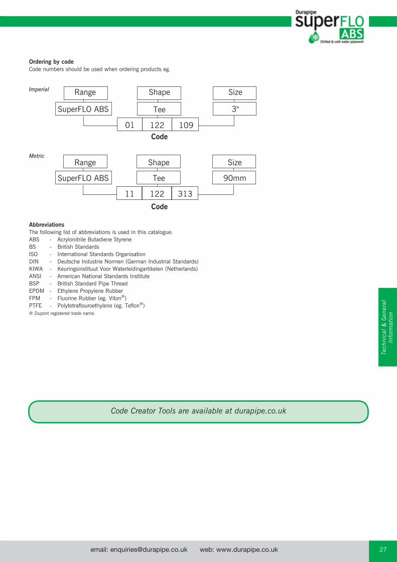
Ordering by code Code numbers should be used when ordering products eg.
Imperial
Metric
Range Shape Size
Tee 3"
12201 109Code
Range Shape Size
SuperFLO ABS
SuperFLO ABS
Tee 90mm
122 31311
Code
Code Creator Tools are available at durapipe.co.uk
Tech
nica
l &
Gen
eral
In
form
atio
n
email: [email protected] web: www.durapipe.co.ukCustomer Services Tel: 0844 800 5509 Fax: 0800 31787528
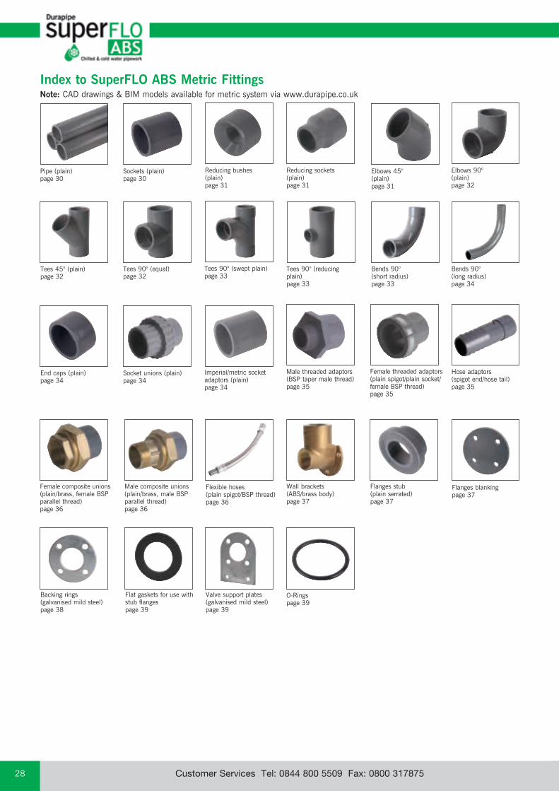
Elbows 90° (plain)page 32
Elbows 45° (plain)page 31
Reducing sockets (plain) page 31
Pipe (plain)page 30
Bends 90° (short radius)page 33
Bends 90° (long radius)page 34
Sockets (plain)page 30
O-Rings page 39
Reducing bushes (plain) page 31
Tees 90° (equal)page 32
Tees 90° (swept plain)page 33
Flat gaskets for use with stub flangespage 39
Backing rings (galvanised mild steel)page 38
Valve support plates (galvanised mild steel) page 39
Flanges blankingpage 37
Flanges stub (plain serrated)page 37
Wall brackets(ABS/brass body) page 37
Male composite unions (plain/brass, male BSP parallel thread) page 36
Female composite unions (plain/brass, female BSP parallel thread) page 36
Hose adaptors (spigot end/hose tail)page 35
Male threaded adaptors (BSP taper male thread) page 35
Female threaded adaptors (plain spigot/plain socket/female BSP thread)page 35
Imperial/metric socket adaptors (plain)page 34
Socket unions (plain)page 34
Tees 45° (plain)page 32
End caps (plain)page 34
Tees 90° (reducing plain)page 33
Index to SuperFLO ABS Metric FittingsNote: CAD drawings & BIM models available for metric system via www.durapipe.co.uk
Flexible hoses (plain spigot/BSP thread) page 36
email: [email protected] web: www.durapipe.co.uk 29Customer Services Tel: 0844 800 5509 Fax: 0800 317875
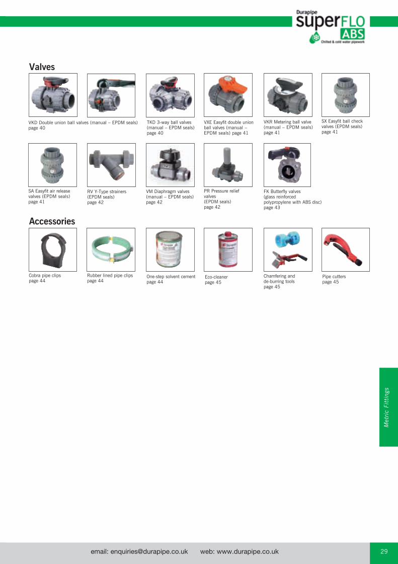
FK Butterfly valves (glass reinforced polypropylene with ABS disc) page 43
Pipe cutters page 45
VM Diaphragm valves (manual – EPDM seals) page 42
RV Y-Type strainers (EPDM seals) page 42
One-step solvent cementpage 44
Eco-cleaner page 45
Cobra pipe clipspage 44
Rubber lined pipe clipspage 44
VKD Double union ball valves (manual – EPDM seals) page 40
TKD 3-way ball valves (manual – EPDM seals) page 40
Valves
Accessories
VXE Easyfit double union ball valves (manual – EPDM seals) page 41
VKR Metering ball valve (manual – EPDM seals) page 41
SA Easyfit air release valves (EPDM seals) page 41
PR Pressure relief valves (EPDM seals) page 42
Chamfering and de-burring tools page 45
SX Easyfit ball check valves (EPDM seals) page 41
Met
ric
Fitt
ings
email: [email protected] web: www.durapipe.co.ukCustomer Services Tel: 0844 800 5509 Fax: 0800 31787530
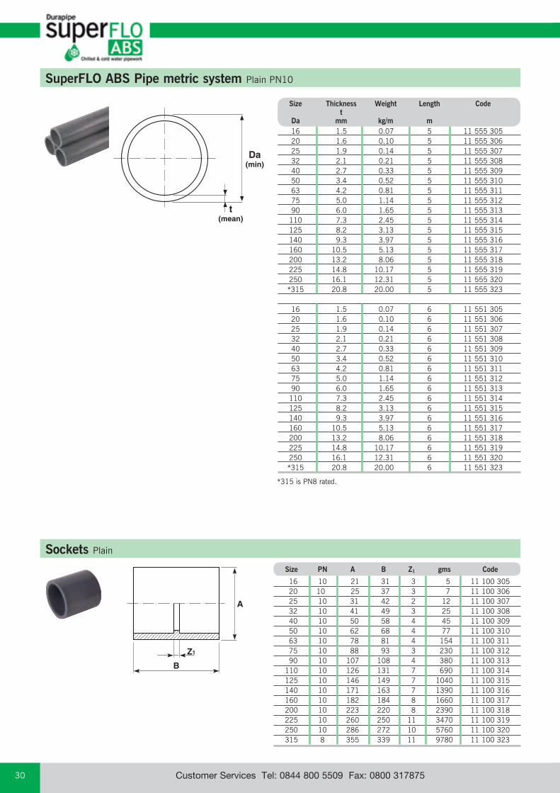
SuperFLO ABS Pipe metric system Plain PN10
16 1.5 0.07 5 11 555 305 20 1.6 0.10 5 11 555 306 25 1.9 0.14 5 11 555 307 32 2.1 0.21 5 11 555 308 40 2.7 0.33 5 11 555 309 50 3.4 0.52 5 11 555 310 63 4.2 0.81 5 11 555 311 75 5.0 1.14 5 11 555 312 90 6.0 1.65 5 11 555 313 110 7.3 2.45 5 11 555 314 125 8.2 3.13 5 11 555 315 140 9.3 3.97 5 11 555 316 160 10.5 5.13 5 11 555 317 200 13.2 8.06 5 11 555 318 225 14.8 10.17 5 11 555 319 250 16.1 12.31 5 11 555 320 *315 20.8 20.00 5 11 555 323
16 1.5 0.07 6 11 551 305 20 1.6 0.10 6 11 551 306 25 1.9 0.14 6 11 551 307 32 2.1 0.21 6 11 551 308 40 2.7 0.33 6 11 551 309 50 3.4 0.52 6 11 551 310 63 4.2 0.81 6 11 551 311 75 5.0 1.14 6 11 551 312 90 6.0 1.65 6 11 551 313 110 7.3 2.45 6 11 551 314 125 8.2 3.13 6 11 551 315 140 9.3 3.97 6 11 551 316 160 10.5 5.13 6 11 551 317 200 13.2 8.06 6 11 551 318 225 14.8 10.17 6 11 551 319 250 16.1 12.31 6 11 551 320 *315 20.8 20.00 6 11 551 323
Size Thickness Weight Length Code t Da mm kg/m m
Da(min)
t(mean)
B
Z1
A
Sockets Plain
Size PN A B Z1 gms Code 16 10 21 31 3 5 11 100 305 20 10 25 37 3 7 11 100 306 25 10 31 42 2 12 11 100 307 32 10 41 49 3 25 11 100 308 40 10 50 58 4 45 11 100 309 50 10 62 68 4 77 11 100 310 63 10 78 81 4 154 11 100 311 75 10 88 93 3 230 11 100 312 90 10 107 108 4 380 11 100 313 110 10 126 131 7 690 11 100 314 125 10 146 149 7 1040 11 100 315 140 10 171 163 7 1390 11 100 316 160 10 182 184 8 1660 11 100 317 200 10 223 220 8 2390 11 100 318 225 10 260 250 11 3470 11 100 319 250 10 286 272 10 5760 11 100 320 315 8 355 339 11 9780 11 100 323
*315 is PN8 rated.

email: [email protected] web: www.durapipe.co.uk 31Customer Services Tel: 0844 800 5509 Fax: 0800 317875
B
d3
Z1
d1 d2
Reducing sockets Plain
PN d3 d2 d1 B Z1 gms Code 10 25 20 16 37 6 6 11 114 412 10 32 25 20 42 6 12 11 114 415 10 40 32 25 50 8 22 11 114 419 10 50 40 32 60 11 39 11 114 423 10 63 50 40 71 11 80 11 114 427 10 75 63 50 85 14 108 11 114 432 10 90 75 63 98 13 190 11 114 438 10 110 90 75 115 16 350 11 114 444 10 125 110 90 140 21 480 11 114 451 10 140 125 110 156 20 690 11 114 459 10 160 140 125 170 20 1000 11 114 467 10 200 160 140 193 23 2180 11 114 476 10 225 200 160 237 41 2530 11 114 487
Z1
A
C
Elbows 45° Plain
Size PN A C Z1 gms Code 16 10 21 20 5 5 11 119 305 20 10 25 22 5 7 11 119 306 25 10 31 26 7 14 11 119 307 32 10 40 31 8 27 11 119 308 40 10 50 37 10 54 11 119 309 50 10 62 45 13 100 11 119 310 63 10 82 54 16 180 11 119 311 75 10 90 63 17 300 11 119 312 90 10 112 70 18 550 11 119 313 110 10 137 90 27 950 11 119 314 125 10 155 103 31 1350 11 119 315 140 10 173 115 37 1980 11 119 316 160 10 190 125 35 2920 11 119 317 200 10 230 152 44 3460 11 119 318 225 10 260 174 51 4920 11 119 319 250 10 286 189 58 5900 11 119 320 315 8 359 230 66 11880 11 119 323
Reducing bushes Plain
Size PN B Z1 gms Code 20 x 16 10 17 3 2 11 109 412 25 x 20 10 19 3 4 11 109 415 32 x 16 10 23 9 5 11 109 417 32 x 25 10 23 8 6 11 109 419 40 x 32 10 28 6 13 11 109 423 50 x 20* 10 33 17 32 11 109 424 50 x 25* 10 33 13 29 11 109 425 50 x 32* 10 32 11 60 11 109 426 50 x 40 10 32 5 40 11 109 427 63 x 25* 10 39 20 60 11 109 429 63 x 32* 10 39 16 60 11 109 430 63 x 50 10 39 7 70 11 109 432 75 x 63 10 46 7 80 11 109 438 90 x 50* 10 54 23 210 11 109 442 90 x 63* 10 54 15 224 11 109 443 90 x 75 10 55 9 150 11 109 444 110 x 63* 10 64 25 252 11 109 449 110 x 90 10 64 10 270 11 109 451 125 x 110 10 72 9 280 11 109 459 140 x 125 10 79 8 300 11 109 467 160 x 90* 10 89 35 320 11 109 473 160 x 110* 10 89 27 660 11 109 474 160 x 140 10 89 10 700 11 109 476 200 x 160 10 110 21 1560 11 109 487 225 x 160* 10 122 33 1600 11 109 495 225 x 200* 10 122 13 1660 11 109 496 250 x 225* 10 132 12 2230 11 109 499 315 x 250* 8 165 33 4220 11 109 503*Configuration shown in inset.
BZ1
BZ1
*
Met
ric
Fitt
ings

email: [email protected] web: www.durapipe.co.ukCustomer Services Tel: 0844 800 5509 Fax: 0800 31787532
A
Z1
C
Elbows 90° Plain
Size PN A C Z1 gms Code
16 10 20 24 10 6 11 115 305 20 10 25 28 11 10 11 115 306 25 10 31 34 15 17 11 115 307 32 10 40 41 18 35 11 115 308 40 10 50 47 20 68 11 115 309 50 10 62 59 26 129 11 115 310 63 10 78 71 31 230 11 115 311 75 10 90 83 38 385 11 115 312 90 10 112 100 49 690 11 115 313 110 10 136 125 63 1220 11 115 314 125 10 155 140 63 1720 11 115 315 140 10 173 153 76 2390 11 115 316 160 10 190 172 79 3600 11 115 317 200 10 235 207 110 4300 11 115 318 225 10 261 240 119 6550 11 115 319 250 10 286 319 188 9560 11 115 320 315 8 359 400 236 17910 11 115 323
C
Z1
BAZ1
Tees 90° Equal
Size PN A B C Z1 gms Code
16 10 21 47 25 10 7 11 122 305 20 10 25 57 30 12 12 11 122 306 25 10 31 67 34 15 24 11 122 307 32 10 40 81 43 18 48 11 122 308 40 10 50 99 50 23 87 11 122 309 50 10 62 119 62 28 160 11 122 310 63 10 78 146 70 34 300 11 122 311 75 10 90 172 87 36 510 11 122 312 90 10 112 205 104 46 900 11 122 313 110 10 132 248 128 60 1650 11 122 314 125 10 154 276 143 67 2300 11 122 315 140 10 172 307 153 72 3200 11 122 316 160 10 191 343 172 86 4800 11 122 317 200 10 237 413 206 101 5800 11 122 318 225 10 262 482 240 120 7700 11 122 319 250 10 286 518 259 128 10160 11 122 320 315 8 360 652 326 162 19390 11 122 323
B
A
Z3
Z1
C
Z2
Tees 45° Plain
Size PN A B C Z1 Z2 Z3 gms Code
20 10 28 68 43 6 26 34 30 11 418 306 25 10 33 81 52 7 29 55 45 11 418 307 32 10 41 98 65 9 42 52 80 11 418 308 40 10 50 117 77 11 51 65 135 11 418 309 50 10 60 140 95 12 63 78 195 11 418 310 63 10 74 169 114 13 76 93 410 11 418 311

email: [email protected] web: www.durapipe.co.uk 33Customer Services Tel: 0844 800 5509 Fax: 0800 317875
C
Z1
D
A
Z3
Z2B
Tees 90° Swept plain
Size PN A B C D Z1 Z2 Z3 gms Code
32 10 41 115 79 79 57 57 14 90 11 148 308 50 10 62 160 105 105 74 74 24 259 11 148 310 63 10 78 195 125 125 87 87 32 480 11 148 311 75 10 92 210 125 125 81 81 41 601 11 148 312 110 10 139 315 190 190 127 127 62 2235 11 148 314
A
D
Z1
C
Z1B
Tees 90° Reducing plain
Size PN A B C D Z1 gms Code
25 x 20 10 31 67 31 25 14 22 11 124 415 32 x 20 10 40 81 35 25 18 40 11 124 418 32 x 25 10 40 81 37 31 18 41 11 124 419 40 x 20 10 50 98 39 25 22 72 11 124 421 40 x 25 10 50 98 41 31 22 72 11 124 422 50 x 20 10 62 119 44 29 27 104 11 124 424 50 x 25 10 62 119 46 31 27 140 11 124 425 50 x 32 10 62 119 50 40 27 140 11 124 426 63 x 25 10 78 146 53 31 34 250 11 124 429 63 x 32 10 78 146 57 40 34 250 11 124 430 75 x 32 10 91 168 62 41 40 391 11 124 435 75 x 40 10 91 168 66 50 40 398 11 124 436 75 x 50 10 91 168 71 61 40 406 11 124 437 75 x 63 10 91 168 78 76 40 428 11 124 438 90 x 40 10 109 198 74 50 48 642 11 124 441 90 x 50 10 109 198 79 61 48 649 11 124 442 90 x 63 10 109 198 86 76 48 664 11 124 443 90 x 75 10 109 198 92 91 48 693 11 124 444 110 x 50 10 133 244 92 61 61 1165 11 124 448 110 x 63 10 133 244 99 76 61 1173 11 124 449 110 x 75 10 133 244 105 91 61 1188 11 124 450 110 x 90 10 133 244 112 109 61 1210 11 124 451
Z1
C
A
Bends 90° Short radius
Size PN A C Z1 gms Code
20 10 26 57 40 18 11 118 306 25 10 33 69 50 38 11 118 307 32 10 41 87 64 75 11 118 308 40 10 51 107 80 135 11 118 309 50 10 62 132 100 245 11 118 310 63 10 78 165 126 470 11 118 311 75 10 93 195 150 810 11 118 312 90 10 111 234 180 1350 11 118 313 110 10 140 284 220 2570 11 118 314
Met
ric
Fitt
ings
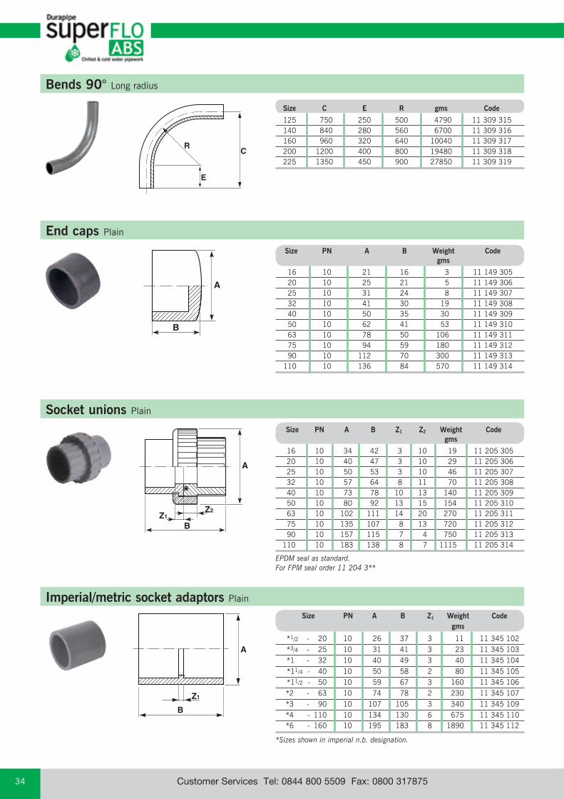
email: [email protected] web: www.durapipe.co.ukCustomer Services Tel: 0844 800 5509 Fax: 0800 31787534
CR
E
Bends 90° Long radius
Size C E R gms Code
125 750 250 500 4790 11 309 315 140 840 280 560 6700 11 309 316 160 960 320 640 10040 11 309 317 200 1200 400 800 19480 11 309 318 225 1350 450 900 27850 11 309 319
B
Z2Z1
A
End caps Plain
Socket unions Plain
Size PN A B Weight Code gms
16 10 21 16 3 11 149 305 20 10 25 21 5 11 149 306 25 10 31 24 8 11 149 307 32 10 41 30 19 11 149 308 40 10 50 35 30 11 149 309 50 10 62 41 53 11 149 310 63 10 78 50 106 11 149 311 75 10 94 59 180 11 149 312 90 10 112 70 300 11 149 313 110 10 136 84 570 11 149 314
Size PN A B Z1 Z2 Weight Code gms
16 10 34 42 3 10 19 11 205 305 20 10 40 47 3 10 29 11 205 306 25 10 50 53 3 10 46 11 205 307 32 10 57 64 8 11 70 11 205 308 40 10 73 78 10 13 140 11 205 309 50 10 80 92 13 15 154 11 205 310 63 10 102 111 14 20 270 11 205 311 75 10 135 107 8 13 720 11 205 312 90 10 157 115 7 4 750 11 205 313 110 10 183 138 8 7 1115 11 205 314
EPDM seal as standard.For FPM seal order 11 204 3**
BZ1
A
Imperial/metric socket adaptors Plain
Size PN A B Z1 Weight Code gms
*1/2 - 20 10 26 37 3 11 11 345 102 *3/4 - 25 10 31 41 3 23 11 345 103 *1 - 32 10 40 49 3 40 11 345 104 *11/4 - 40 10 50 58 2 80 11 345 105 *11/2 - 50 10 59 67 3 160 11 345 106 *2 - 63 10 74 78 2 230 11 345 107 *3 - 90 10 107 105 3 340 11 345 109 *4 - 110 10 134 130 6 675 11 345 110 *6 - 160 10 195 183 8 1890 11 345 112
*Sizes shown in imperial n.b. designation.
B
A

email: [email protected] web: www.durapipe.co.uk 35Customer Services Tel: 0844 800 5509 Fax: 0800 317875
Z1
Z2
B
d1 d2 AT
Female threaded adaptors Plain spigot/plain socket/female BSP thread
Size Weight d2 d1 PN T* A B Z1 Z2 gms Code
16- 12- 10 3⁄8 24 28 11 16 7 11 153 331 20- 16- 10 1⁄2 30 35 15 21 14 11 153 333 25- 20- 10 3⁄4 38 39 16 22 21 11 153 335 32- 25- 10 1 45 45 18 26 42 11 153 337 40- 32- 10 11⁄4 56 54 21 31 69 11 153 339 50- 40- 10 11⁄2 64 60 21 33 108 11 153 341 63- 50- 10 2 78 72 25 41 169 11 153 343
*Thread size designation.
Male threaded adaptors BSP taper male thread
B
Z1
D
A(A/F)d2 d1
Size Weight d2 d1 PN T* A B D Z1 gms Code
16- 12- 10 3⁄8 19 35 11 22 7 11 151 331 20- 16- 10 3⁄8 24 38 12 24 7 11 151 332 20- 16- 10 1⁄2 24 42 15 28 7 11 151 333 20- 16- 10 3⁄4 30 46 16 28 8 11 151 327 25- 20- 10 1⁄2 30 46 15 28 13 11 151 334 25- 20- 10 3⁄4 30 48 16 31 14 11 151 335 32- 25- 10 1⁄2 36 51 15 32 23 11 151 352 32- 25- 10 3⁄4 36 52 16 33 23 11 151 336 32- 25- 10 1 36 55 19 36 23 11 151 337 40- 32- 10 1 46 58 20 36 36 11 151 338 40- 32- 10 11⁄4 46 60 21 37 38 11 151 339 50- 40- 10 11⁄4 55 66 22 39 70 11 151 340 50- 40- 10 11⁄2 55 66 21 39 70 11 151 341 63- 50- 10 11⁄2 72 73 22 41 115 11 151 342 63- 50- 10 2 72 78 26 46 123 11 151 343 75- 63- 10 2 80 84 26 46 150 11 151 345
*Thread size designation.
D
B
Hose adaptors Spigot end/hose tail
Size PN B D Weight Code gms 16 10 60 25 8 11 158 305 20 10 75 30 13 11 158 306 25 10 80 35 20 11 158 307 32 10 90 40 32 11 158 308
Met
ric
Fitt
ings

email: [email protected] web: www.durapipe.co.ukCustomer Services Tel: 0844 800 5509 Fax: 0800 31787536
Female composite unions Plain/brass, female BSP parallel thread
Male composite unions Plain/brass, male BSP taper thread
Z1
A(A/F)
B
Z2
B
Z1
A(A/F)
Size PN A B Z1 Z2 Weight Code gms
16 x 3⁄8* 10 32 37 3 7 105 11 216 305
20 x 1⁄2* 10 40 43 3 7 175 11 216 306
25 x 3⁄4* 10 48 47 3 7 320 11 216 307
32 x 1* 10 55 59 8 9 420 11 216 308
40 x 11⁄4* 10 65 68 10 8 620 11 216 309
50 x 11⁄2* 10 78 76 12 9 1000 11 216 310
63 x 2* 10 88 89 12 11 1200 11 216 311
*Thread sizes designation.Fitted with brass retaining nut and EPDM rubber seal.Brass material to BS2872, WRAS approved.
Size PN A B Z1 Z2 Weight Code gms
16 x 3⁄8* 10 32 48 3 9 100 11 217 305
20 x 1⁄2* 10 40 54 3 9 165 11 217 306
25 x 3⁄4* 10 48 74 3 10 250 11 217 307
32 x 1* 10 55 86 8 11 310 11 217 308
40 x 11⁄4* 10 65 94 10 11 450 11 217 309
50 x 11⁄2* 10 78 108 12 12 800 11 217 310
63 x 2* 10 88 126 12 14 950 11 217 311
*Thread sizes designation. Fitted with brass retaining nut and EPDM rubber seal.Brass material to BS2872, WRAS approved.
Size Code
20 x 1⁄2" x 300 11450306
25 x 3⁄4" x 300 11450307
32 x 1" x 300 11450308
20 x 1⁄2" x 600 11451306
25 x 3⁄4" x 600 11451307
32 x 1" x 600 11451308
10 bar working pressure at 20°C.Other lengths available on request.
Flexible hoses Plain spigot, BSP thread
ALL Durapipe Brass Components are manufactured using DZR Brass.
ALL Durapipe Brass Components are manufactured using DZR Brass.
ALL Durapipe Brass Components are manufactured using DZR Brass.
Product is approved to BSRIA BG4-2004

email: [email protected] web: www.durapipe.co.uk 37Customer Services Tel: 0844 800 5509 Fax: 0800 317875
Wall brackets ABS/brass body
BA
Z2
Z1 C
D
Size PN A B C D Z1 Z2 Weight Code gms
16- 3⁄8* 10 15 4.5 6 19 17 9 180 31 422 326
20- 1⁄2* 10 16.5 4.5 6 19 18 9 185 31 422 327
25- 1⁄2* 10 20 4.5 5 24 19 11 215 31 422 328
25- 3⁄4* 10 20 4.5 5 24 19 11 200 31 422 329
*Thread sizes designation.
ALL Durapipe Brass Components are manufactured using DZR Brass.
B
AK
L
B
D
Z1
A
Flanges stub Plain serrated
Flanges blanking
Size PN A B D Z1 Weight gms Code
16 10 29 17 6 3 5 11 135 305 20 10 34 20 6 3 8 11 135 306 25 10 41 22 7 3 13 11 135 307 32 10 50 26 7 3 19 11 135 308 40 10 61 30 8 3 36 11 135 309 50 10 73 35 8 3 60 11 135 310 63 10 90 42 9 4 100 11 135 311 75 10 106 49 10 4 150 11 135 312 90 10 125 59 11 6 240 11 135 313 110 10 149 68 12 6 370 11 135 314 125 10 165 76 13 5 520 11 135 315 140 10 180 83 14 7 680 11 135 316 160 10 205 93 16 5 930 11 135 317 200* 10 252 114 17 6 1300 11 135 318 225 10 273 126 24 6 1470 11 135 319 250 10 306 140 20 9 2140 11 135 320 315 10 375 180 32 14 5000 11 135 323
DIN 2501 16 bar/PN16 No. Weight Size PN A B K L Holes gms Code
32 10 116 13 85 14 4 139 11 323 308 40 10 141 13 100 18 4 204 11 323 309 50 10 153 13 110 18.5 4 237 11 323 310 63 10 166 19 124 18 4 447 11 323 311 75 10 186 19 145 18.5 4 568 11 323 312 90 10 201 19 159 18 8 645 11 323 313 110 10 221 26 180 18 8 715 11 323 314 125 10 251 26 210 18 8 1338 11 323 315 140 10 251 26 210 18 8 1338 11 323 316 160 10 286 27 240 23 8 1720 11 323 317
*The 200mm (NW175) stub flange supplied by Durapipe when used in conjunction with backing ring; code number 421 318 and 420 318 has a bolt circle diameter which matches 225mm (NW200) flanges (295mm PCD).
Note: Durapipe backing rings must be used in conjunction with blank flanges.
Met
ric
Fitt
ings
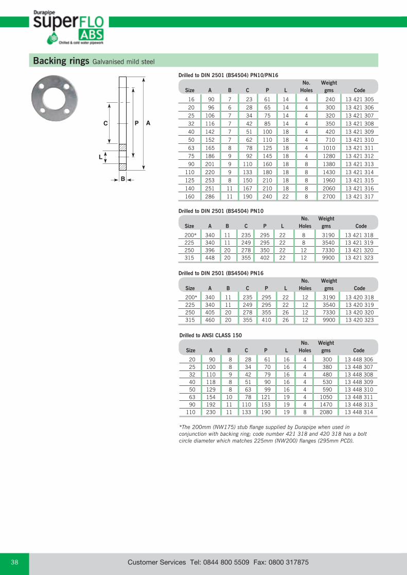
email: [email protected] web: www.durapipe.co.ukCustomer Services Tel: 0844 800 5509 Fax: 0800 31787538
Drilled to ANSI CLASS 150 No. Weight Size A B C P L Holes gms Code
20 90 8 28 61 16 4 300 13 448 306 25 100 8 34 70 16 4 380 13 448 307 32 110 9 42 79 16 4 480 13 448 308 40 118 8 51 90 16 4 530 13 448 309 50 129 8 63 99 16 4 590 13 448 310 63 154 10 78 121 19 4 1050 13 448 311 90 192 11 110 153 19 4 1470 13 448 313 110 230 11 133 190 19 8 2080 13 448 314
B
AC P
L
Backing rings Galvanised mild steel
Drilled to DIN 2501 (BS4504) PN10/PN16 No. Weight Size A B C P L Holes gms Code
16 90 7 23 61 14 4 240 13 421 305 20 96 6 28 65 14 4 300 13 421 306 25 106 7 34 75 14 4 320 13 421 307 32 116 7 42 85 14 4 350 13 421 308 40 142 7 51 100 18 4 420 13 421 309 50 152 7 62 110 18 4 710 13 421 310 63 165 8 78 125 18 4 1010 13 421 311 75 186 9 92 145 18 4 1280 13 421 312 90 201 9 110 160 18 8 1380 13 421 313 110 220 9 133 180 18 8 1430 13 421 314 125 253 8 150 210 18 8 1960 13 421 315 140 251 11 167 210 18 8 2060 13 421 316 160 286 11 190 240 22 8 2700 13 421 317
Drilled to DIN 2501 (BS4504) PN16 No. Weight Size A B C P L Holes gms Code
200* 340 11 235 295 22 12 3190 13 420 318 225 340 11 249 295 22 12 3540 13 420 319 250 405 20 278 355 26 12 7330 13 420 320 315 460 20 355 410 26 12 9900 13 420 323
Drilled to DIN 2501 (BS4504) PN10 No. Weight Size A B C P L Holes gms Code
200* 340 11 235 295 22 8 3190 13 421 318 225 340 11 249 295 22 8 3540 13 421 319 250 396 20 278 350 22 12 7330 13 421 320 315 448 20 355 402 22 12 9900 13 421 323
*The 200mm (NW175) stub flange supplied by Durapipe when used in conjunction with backing ring; code number 421 318 and 420 318 has a bolt circle diameter which matches 225mm (NW200) flanges (295mm PCD).
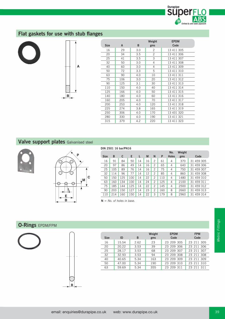
email: [email protected] web: www.durapipe.co.uk 39Customer Services Tel: 0844 800 5509 Fax: 0800 317875
B
A
Flat gaskets for use with stub flanges Weight EPDM Size A B gms Code
16 29 3.0 2 13 411 305 20 34 3.5 2 13 411 306 25 41 3.5 3 13 411 307 32 50 3.0 4 13 411 308 40 60 3.0 4 13 411 309 50 72 3.3 5 13 411 310 63 90 4.0 10 13 411 311 75 106 3.0 20 13 411 312 90 125 3.1 30 13 411 313 110 150 4.0 40 13 411 314 125 166 4.0 50 13 411 315 140 180 4.0 60 13 411 316 160 205 4.0 70 13 411 317 200 253 4.0 120 13 411 318 225 274 3.8 165 13 411 319 250 306 4.0 170 13 431 320 280 330 4.0 190 13 411 321 315 379 4.2 220 13 411 323
CM
L
EB
P
Valve support plates Galvanised steel
DIN 2501 16 bar/PN16 No. Weight Size B C E L M N P Holes gms Code
16 91 84 50 14 16 2 61 4 370 31 459 305 20 97 86 49 14 16 2 65 4 640 31 459 306 25 105 89 76 14 16 2 75 4 750 31 459 307 32 114 96 77 14 12 2 85 4 860 31 459 308 50 150 125 100 14 22 2 110 4 1480 31 459 310 63 160 134 100 14 24 2 125 4 2100 31 459 311 75 185 144 125 14 22 2 145 4 2500 31 459 312 90 203 150 127 14 23 2 160 8 2660 31 459 313 110 214 160 150 14 22 3 179 8 2960 31 459 314
N = No. of holes in base.
O-Rings EPDM/FPM
Weight EPDM FPM Size ID B gms Code Code
16 15.54 2.62 23 23 209 305 23 211 305 20 20.22 3.53 39 23 209 306 23 211 306 25 28.17 3.53 68 23 209 307 23 211 307 32 32.93 3.53 94 23 209 308 23 211 308 40 40.65 5.34 163 23 209 309 23 211 309 50 47.00 5.34 190 23 209 310 23 211 310 63 59.69 5.34 355 23 209 311 23 211 311
B
Met
ric
Fitt
ings
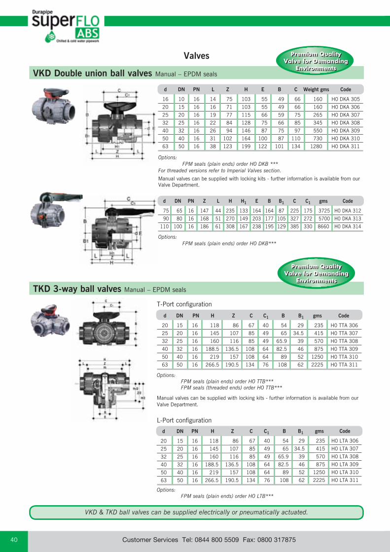
email: [email protected] web: www.durapipe.co.ukCustomer Services Tel: 0844 800 5509 Fax: 0800 31787540
VKD Double union ball valves Manual – EPDM seals
Options: FPM seals (plain ends) order H0 DKB ***For threaded versions refer to Imperial Valves section.
Manual valves can be supplied with locking kits - further information is available from our Valve Department.
T-Port configuration
L-Port configuration
Options: FPM seals (plain ends) order H0 DKB***
d DN PN Z L H H1 E B B1 C C1 gms Code
75 65 16 147 44 235 133 164 164 87 225 175 3725 H0 DKA 312
90 80 16 168 51 270 149 203 177 105 327 272 5700 H0 DKA 313
110 100 16 186 61 308 167 238 195 129 385 330 8660 H0 DKA 314
TKD 3-way ball valves Manual – EPDM seals
Options: FPM seals (plain ends) order H0 TTB*** FPM seals (threaded ends) order H0 TTB***
Manual valves can be supplied with locking kits - further information is available from our Valve Department.
Options: FPM seals (plain ends) order H0 LTB***
d DN PN H Z C C1 B B1 gms Code
20 15 16 118 86 67 40 54 29 235 H0 LTA 306
25 20 16 145 107 85 49 65 34.5 415 H0 LTA 307
32 25 16 160 116 85 49 65.9 39 570 H0 LTA 308
40 32 16 188.5 136.5 108 64 82.5 46 875 H0 LTA 309
50 40 16 219 157 108 64 89 52 1250 H0 LTA 310
63 50 16 266.5 190.5 134 76 108 62 2225 H0 LTA 311
d DN PN L Z H E B C Weight gms Code
16 10 16 14 75 103 55 49 66 160 H0 DKA 305
20 15 16 16 71 103 55 49 66 160 H0 DKA 306
25 20 16 19 77 115 66 59 75 265 H0 DKA 307
32 25 16 22 84 128 75 66 85 345 H0 DKA 308
40 32 16 26 94 146 87 75 97 550 H0 DKA 309
50 40 16 31 102 164 100 87 110 730 H0 DKA 310
63 50 16 38 123 199 122 101 134 1280 H0 DKA 311
d DN PN H Z C C1 B B1 gms Code
20 15 16 118 86 67 40 54 29 235 H0 TTA 306
25 20 16 145 107 85 49 65 34.5 415 H0 TTA 307
32 25 16 160 116 85 49 65.9 39 570 H0 TTA 308
40 32 16 188.5 136.5 108 64 82.5 46 875 H0 TTA 309
50 40 16 219 157 108 64 89 52 1250 H0 TTA 310
63 50 16 266.5 190.5 134 76 108 62 2225 H0 TTA 311
Valves
Premium Quality Valve for Demanding
Environments
Premium Quality Valve for Demanding
Environments
Premium Quality Valve for Demanding
Environments
Premium Quality Valve for Demanding
Environments
VKD & TKD ball valves can be supplied electrically or pneumatically actuated.
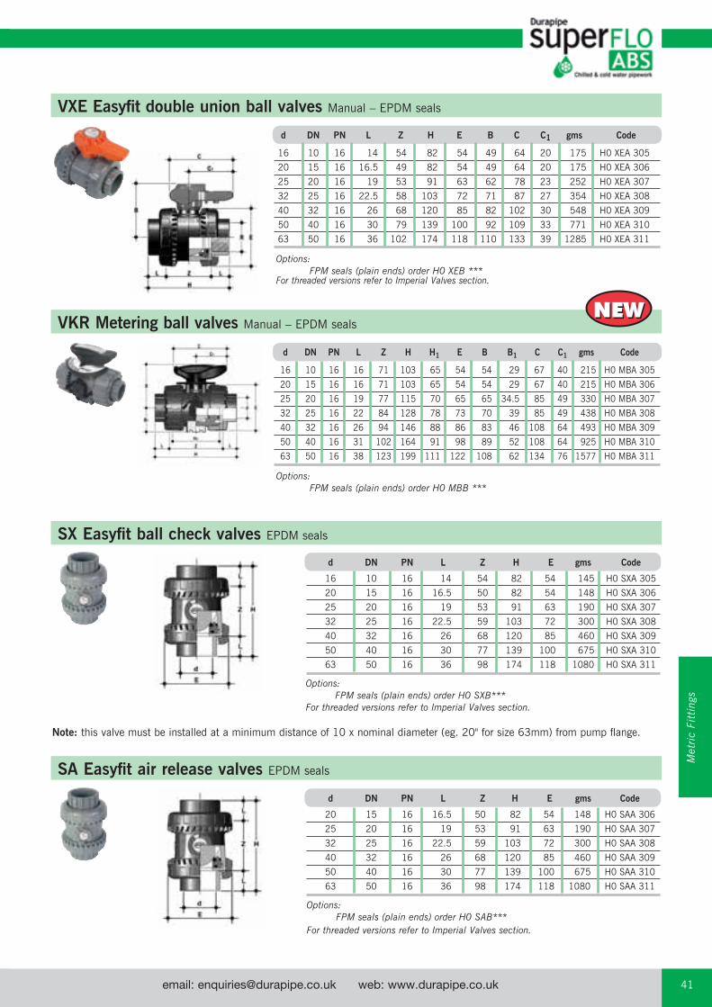
email: [email protected] web: www.durapipe.co.uk 41Customer Services Tel: 0844 800 5509 Fax: 0800 317875
d DN PN L Z H H1 E B B1 C C1 gms Code
16 10 16 16 71 103 65 54 54 29 67 40 215 H0 MBA 305
20 15 16 16 71 103 65 54 54 29 67 40 215 H0 MBA 306
25 20 16 19 77 115 70 65 65 34.5 85 49 330 H0 MBA 307
32 25 16 22 84 128 78 73 70 39 85 49 438 H0 MBA 308
40 32 16 26 94 146 88 86 83 46 108 64 493 H0 MBA 309
50 40 16 31 102 164 91 98 89 52 108 64 925 H0 MBA 310
63 50 16 38 123 199 111 122 108 62 134 76 1577 H0 MBA 311
SX Easyfit ball check valves EPDM seals
Options: FPM seals (plain ends) order H0 SXB***For threaded versions refer to Imperial Valves section.
SA Easyfit air release valves EPDM seals
Options: FPM seals (plain ends) order H0 SAB***For threaded versions refer to Imperial Valves section.
Note: this valve must be installed at a minimum distance of 10 x nominal diameter (eg. 20" for size 63mm) from pump flange.
VXE Easyfit double union ball valves Manual – EPDM seals
VKR Metering ball valves Manual – EPDM sealsNEWNEW
d DN PN L Z H E B C C1 gms Code
16 10 16 14 54 82 54 49 64 20 175 H0 XEA 305
20 15 16 16.5 49 82 54 49 64 20 175 H0 XEA 306
25 20 16 19 53 91 63 62 78 23 252 H0 XEA 307
32 25 16 22.5 58 103 72 71 87 27 354 H0 XEA 308
40 32 16 26 68 120 85 82 102 30 548 H0 XEA 309
50 40 16 30 79 139 100 92 109 33 771 H0 XEA 310
63 50 16 36 102 174 118 110 133 39 1285 H0 XEA 311
Options: FPM seals (plain ends) order H0 XEB ***For threaded versions refer to Imperial Valves section.
Options: FPM seals (plain ends) order H0 MBB ***
d DN PN L Z H E gms Code
16 10 16 14 54 82 54 145 H0 SXA 305
20 15 16 16.5 50 82 54 148 H0 SXA 306
25 20 16 19 53 91 63 190 H0 SXA 307
32 25 16 22.5 59 103 72 300 H0 SXA 308
40 32 16 26 68 120 85 460 H0 SXA 309
50 40 16 30 77 139 100 675 H0 SXA 310
63 50 16 36 98 174 118 1080 H0 SXA 311
d DN PN L Z H E gms Code
20 15 16 16.5 50 82 54 148 H0 SAA 306
25 20 16 19 53 91 63 190 H0 SAA 307
32 25 16 22.5 59 103 72 300 H0 SAA 308
40 32 16 26 68 120 85 460 H0 SAA 309
50 40 16 30 77 139 100 675 H0 SAA 310
63 50 16 36 98 174 118 1080 H0 SAA 311
Met
ric
Fitt
ings

email: [email protected] web: www.durapipe.co.ukCustomer Services Tel: 0844 800 5509 Fax: 0800 31787542
RV Y-Type strainers Plain ends – EPDM seals
VM Diaphragm valves Manual – plain union ends – EPDM seals
Options: FPM diaphragm order H0 VMB*** PTFE diaphragm order H0 VMC***
d DN PN B B1 H h H1 J L gms Code
20 15 10 95 26 124 12 90 M6 16 690 H0 UMA 306
25 20 10 95 26 144 12 90 M6 19 690 H0 UMA 307
32 25 10 95 26 154 12 90 M6 23 720 H0 UMA 308
40 32 10 126 40 174 18 115 M8 27 1520 H0 UMA 309
50 40 10 126 40 194 18 115 M8 32 1545 H0 UMA 310
63 50 10 148 40 224 18 140 M8 39 2275 H0 UMA 311
75 65 10 225 55 284 23 215 M12 44 6225 H0 VMA 412
90 80 10 225 55 300 23 215 M12 51 6440 H0 VMA 413
110 100 10 295 69 350 23 250 M12 61 9015 H0 VMA 414
D DN PN A B E L Z H Fig. gms Code Grey max
20 15 16 125 72 55 16 103 135 A 211 H0 UVA 306
25 20 16 145 84 66 19 120 158 A 358 H0 UVA 307
32 25 16 165 95 75 22 132 176 A 526 H0 UVA 308
40 32 16 190 111 87 26 155 207 A 733 H0 UVA 309
50 40 16 210 120 100 31 181 243 A 1095 H0 UVA 310
63 50 10 240 139 120 38 222 298 A 1843 H0 UVA 311
Options: FPM seals (plain ends) order H0 UVB ***For threaded versions refer to Imperial Valves section.
PR Pressure relief valves EPDM seals
C
ZEG
B
A
D
F
Size PN Z A B C D E F G gms Code
20 10 92 143 20.5 35 124 M6 25 12 700 H0 PRA 406
25 10 106 143 20.5 35 144 M6 25 12 700 H0 PRA 407
32 10 108 143 25.0 35 154 M6 25 12 700 H0 PRA 408
40 10 120 204 36.0 50 174 M8 44.5 16 1500 H0 PRA 409
50 10 130 204 39.5 50 194 M8 44.5 16 1500 H0 PRA 410
63 10 146 219 49.0 50 224 M8 44.5 16 2400 H0 PRA 411
Options: FPM seals order H0 PRB***
*
*
*
*Note: 75mm, 90mm and 110mm are spigot ended.

email: [email protected] web: www.durapipe.co.uk 43Customer Services Tel: 0844 800 5509 Fax: 0800 317875
FK Butterfly valves Glass reinforced polypropylene with ABS disc
Size DN PN B2 B5 B6 G G1 G2 G3 gms U Z Code
75 65 10 80 174 146 48 135 39 125 2400 4 46 HV FKA 108 90 80 10 93 188 160 48 135 39 125 2800 8 49 HV FKA 109 110 100 10 107 202 174 48 135 39 125 3150 8 56 HV FKA 110 140 125 10 120 222 194 48 144 39 200 4450 8 64 HV FKA 111 160 150 10 134 235 207 48 144 39 200 5200 8 70 HV FKA 112 225 200 10 161 287 256 65 204 60 200 9300 8 71 HV FKA 113 250 250 10 210 317 281 88 236 76 250 18600 12 114 HV FKA 114 315 300 8 245 374 338 88 236 76 250 25600 12 114 HV FKA 115
with gear box
lever operated
Options: FPM seals order HV FKB***
Options: FPM seals order H0 FKB***
Note: Lugged versions available to special order. Please refer to our Valve Department for further details.
d DN PN B2 B3 C C1 gms U Z Code
50 40 16 60 137 175 100 900 4 33 H0 FKA 106 63 50 16 70 143 175 100 1080 4 43 H0 FKA 107 75 65 10 80 164 272 110 1470 4 46 H0 FKA 108 90 80 10 93 178 272 110 1870 8 49 H0 FKA 109 110 100 10 107 192 272 110 2220 8 56 H0 FKA 110 140 125 10 120 212 330 110 3100 8 64 H0 FKA 111 160 150 10 134 225 330 110 3850 8 70 H0 FKA 112 225 200 10 161 272 420 122 6750 8 71 H0 FKA 113
U = No. of holes
U = No. of holes
Valves can be supplied as electrically or pneumatically actuated. For further details contact our Valve department on 01543 272424.
Met
ric
Fitt
ings
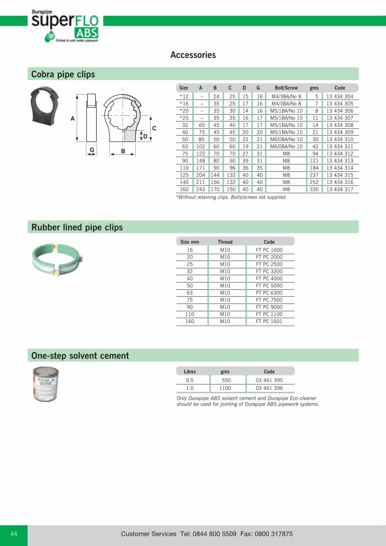
email: [email protected] web: www.durapipe.co.ukCustomer Services Tel: 0844 800 5509 Fax: 0800 31787544
Accessories
Cobra pipe clips
BG
C
A
D
Size A B C D G Bolt/Screw gms Code
*12 – 24 25 15 16 M4/3BA/No 8 5 13 434 304 *16 – 35 25 17 16 M4/3BA/No 8 7 13 434 305 *20 – 35 30 14 16 M5/1BA/No 10 8 13 434 306 *25 – 35 35 16 17 M5/1BA/No 10 11 13 434 307 32 65 45 40 17 17 M5/1BA/No 10 14 13 434 308 40 75 45 45 20 20 M5/1BA/No 10 21 13 434 309 50 85 50 50 22 21 M6/0BA/No 10 30 13 434 310 63 102 60 60 19 21 M6/0BA/No 10 42 13 434 311 75 122 70 70 27 31 M8 94 13 434 312 90 148 80 90 39 31 M8 121 13 434 313 110 171 90 96 36 35 M8 184 13 434 314 125 204 144 132 40 40 M8 237 13 434 315 140 211 156 132 40 40 M8 252 13 434 316 160 243 170 150 40 40 M8 330 13 434 317
*Without retaining clips. Bolts/screws not supplied.
One-step solvent cement
Only Durapipe ABS solvent cement and Durapipe Eco-cleaner should be used for jointing of Durapipe ABS pipework systems.
Litres gms Code
0.5 550 03 461 395
1.0 1100 03 461 396
Rubber lined pipe clips Size mm Thread Code
16 M10 FT PC 1600 20 M10 FT PC 2000 25 M10 FT PC 2500 32 M10 FT PC 3200 40 M10 FT PC 4000 50 M10 FT PC 5000 63 M10 FT PC 6300 75 M10 FT PC 7500 90 M10 FT PC 9000 110 M10 FT PC 1100 160 M10 FT PC 1601
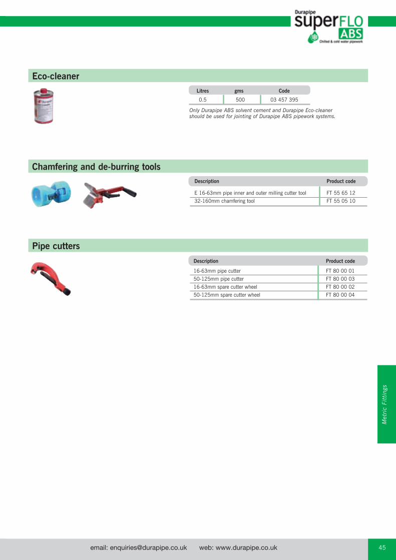
email: [email protected] web: www.durapipe.co.uk 45Customer Services Tel: 0844 800 5509 Fax: 0800 317875
Eco-cleaner Litres gms Code
0.5 500 03 457 395
Only Durapipe ABS solvent cement and Durapipe Eco-cleaner should be used for jointing of Durapipe ABS pipework systems.
Chamfering and de-burring tools
Pipe cutters
Description Product code
E 16-63mm pipe inner and outer milling cutter tool FT 55 65 12
32-160mm chamfering tool FT 55 05 10
Description Product code
16-63mm pipe cutter FT 80 00 01
50-125mm pipe cutter FT 80 00 03
16-63mm spare cutter wheel FT 80 00 02
50-125mm spare cutter wheel FT 80 00 04
Met
ric
Fitt
ings
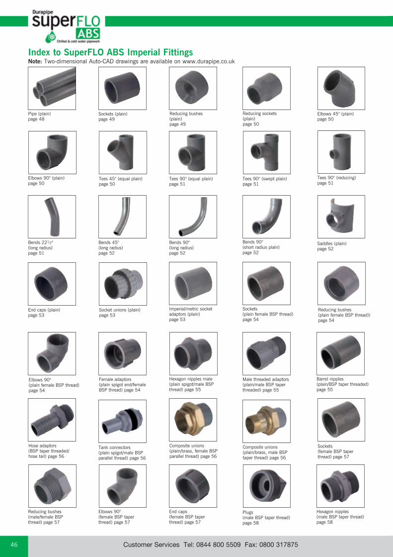
email: [email protected] web: www.durapipe.co.ukCustomer Services Tel: 0844 800 5509 Fax: 0800 31787546
Index to SuperFLO ABS Imperial FittingsNote: Two-dimensional Auto-CAD drawings are available on www.durapipe.co.uk
Reducing sockets (plain)page 50
Pipe (plain)page 48
Sockets (plain)page 49
Bends 221⁄2° (long radius)page 51
Bends 45° (long radius)page 52
Bends 90° (long radius)page 52
Bends 90° (short radius plain)page 52
Socket unions (plain)page 53
End caps (plain)page 53
Tees 45° (equal plain)page 50
Sockets (plain female BSP thread)page 54
Imperial/metric socket adaptors (plain)page 53
Sockets (female BSP taper thread) page 57
Elbows 90° (plain female BSP thread) page 54
Reducing bushes (plain female BSP thread))page 54
Composite unions (plain/brass, male BSP taper thread) page 56
Female adaptors (plain spigot end/female BSP thread) page 54
Hose adaptors (BSP taper threaded/ hose tail) page 56
Male threaded adaptors (plain/male BSP taper threaded) page 55
Barrel nipples (plain/BSP taper threaded) page 55
Hexagon nipples (male BSP taper thread) page 58
Hexagon nipples male (plain spigot/male BSP thread) page 55
Tank connectors (plain spigot/male BSP parallel thread) page 56
Tees 90° (equal plain)page 51
Elbows 90° (plain)page 50
Elbows 45° (plain)page 50
Reducing bushes (plain)page 49
Saddles (plain)page 52
Tees 90° (swept plain) page 51
Tees 90° (reducing)page 51
Reducing bushes (male/female BSP thread) page 57
Elbows 90° (female BSP taper thread) page 57
End caps (female BSP taper thread) page 57
Plugs (male BSP taper thread) page 58
Composite unions (plain/brass, female BSP parallel thread) page 56
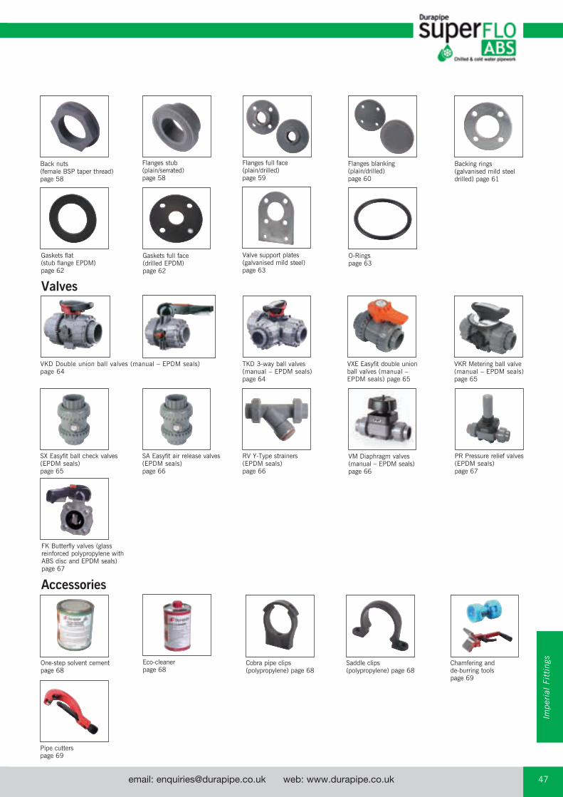
email: [email protected] web: www.durapipe.co.uk 47Customer Services Tel: 0844 800 5509 Fax: 0800 317875
Back nuts (female BSP taper thread) page 58
One-step solvent cement page 68
Cobra pipe clips (polypropylene) page 68
Saddle clips (polypropylene) page 68
Pipe cutters page 69
Gaskets full face (drilled EPDM) page 62
O-Rings page 63
Valve support plates (galvanised mild steel) page 63
Backing rings (galvanised mild steel drilled) page 61
Eco-cleaner page 68
Gaskets flat (stub flange EPDM) page 62
VM Diaphragm valves (manual – EPDM seals)page 66
SX Easyfit ball check valves (EPDM seals) page 65
SA Easyfit air release valves (EPDM seals) page 66
RV Y-Type strainers (EPDM seals) page 66
PR Pressure relief valves (EPDM seals) page 67
FK Butterfly valves (glass reinforced polypropylene with ABS disc and EPDM seals) page 67
Flanges stub (plain/serrated) page 58
VKD Double union ball valves (manual – EPDM seals) page 64
VXE Easyfit double union ball valves (manual – EPDM seals) page 65
VKR Metering ball valve (manual – EPDM seals) page 65
TKD 3-way ball valves (manual – EPDM seals) page 64
Flanges full face (plain/drilled) page 59
Flanges blanking (plain/drilled) page 60
Valves
Accessories
Chamfering and de-burring tools page 69
Impe
rial
Fit
ting
s

email: [email protected] web: www.durapipe.co.ukCustomer Services Tel: 0844 800 5509 Fax: 0800 31787548
SuperFLO ABS Pipe imperial system Plain
d1 (mean)
t (mean)
Mean OD Thickness Length Weight Code Size d1 t (mm) (m) kg/m 3/8 17.1 1.7 6 0.09 01 513 101 1/2 21.4 2.0 6 0.13 01 513 102 3/4 26.7 2.5 6 0.20 01 513 103 1 33.6 3.1 6 0.31 01 513 104 11/4 42.2 3.9 6 0.49 01 513 105 11/2 48.3 4.5 6 0.64 01 513 106 2 60.3 5.6 6 1.00 01 513 107 3 88.9 8.3 6 2.16 01 513 109 4 114.3 10.6 6 3.59 01 513 110
Mean OD Thickness Length Weight Code Size d1 t (mm) (m) kg/m 6 168.3 12.8 6 6.50 01 512 112
Mean OD Thickness Length Weight Code Size d1 t (mm) (m) kg/m 1 33.6 2.0 6 0.21 01 511 104 11/4 42.2 2.5 6 0.32 01 511 105 11/2 48.3 2.8 6 0.42 01 511 106 2 60.3 3.6 6 0.67 01 511 107 21/2 75.2 5.0 6 1.14 11 551 312 3 88.9 5.2 6 1.40 01 511 109 4 114.3 6.6 6 2.32 01 511 110 5 140.2 9.3 6 3.97 11 551 316 6 168.3 9.9 6 5.12 01 511 112 8 219.1 12.7 6 8.57 01 511 113
*Note: 21/2" & 5" pipes dimensionally compatible with 75mm and 140mm PN10 Metric series and are manufactured in accordance with the general requirements of DIN 8061/8062.
Mean OD Thickness Length Weight Code Size d1 t (mm) (m) kg/m
3/8 17.1 3.5 6 0.16 01 514 101 1/2 21.4 3.6 6 0.22 01 514 102 3/4 26.7 3.6 6 0.28 01 514 103 1 33.6 4.3 6 0.43 01 514 104 11/4 42.2 5.3 6 0.65 01 514 105 11/2 48.3 6.0 6 0.85 01 514 106 2 60.3 7.2 6 1.28 01 514 107
Pipe - ABS Class T (for threading) 173 psig (12 bar after threading)
Pipe - ABS Class E 217psig (15 bar)
Pipe - ABS Class D 173psig (12 bar)
Pipe - ABS Class C 130psig (9 bar)

email: [email protected] web: www.durapipe.co.uk 49Customer Services Tel: 0844 800 5509 Fax: 0800 317875
Sockets Plain
B
Z1
A
Size PN A B Z1 gms Code
3/8 15 21 32 2 4 01 100 101 1/2 15 26 38 2 6 01 100 102 3/4 15 32 43 3 12 01 100 103 1 15 41 50 3 24 01 100 104 11/4 15 52 60 4 41 01 100 105 11/2 15 60 66 2 62 01 100 106 2 15 74 78 4 114 01 100 107 21/2 10 88 94 4 230 11 100 312 3 15 108 104 4 355 01 100 109 4 15 136 135 5 595 01 100 110 5 10 171 163 7 1390 11 100 316 6 12 201 191 9 2269 01 100 112 8 9 257 249 11 3668 01 100 113
Reducing bushes Plain
BZ1
Size PN B Z1 gms Code
1/2 x 3/8 15 17 2 7 01 109 121
3/4 x 1/2 15 20 3 8 01 109 122
1 x 1/2 15 23 6 23 01 109 123
1 x 3/4 15 24 4 15 01 109 124
*11/4 x 1/2 15 28 12 21 01 109 116
*11/4 x 3/4 15 28 8 24 01 109 117
11/4 x 1 15 28 5 20 01 109 125
*11/2 x 1/2 15 30 13 26 01 109 118
*11/2 x 3/4 15 30 10 37 01 109 119
*11/2 x 1 15 30 7 40 01 109 126
11/2 x 11/4 15 31 4 19 01 109 127
*2 x 3/4 15 38 15 45 01 109 120
*2 x 1 15 38 15 45 01 109 128
*2 x 11/4 15 38 11 57 01 109 129
2 x 11/2 15 37 7 42 01 109 130
21/2 x 2 15 44 8 75 01 109 131
*3 x 11/2 15 51 21 130 01 109 134
*3 x 2 15 51 15 178 01 109 135
3 x 21/2 15 50 6 126 01 109 136
*4 x 3 15 65 12 277 01 109 141
5 x 4 15 78 15 413 01 329 142
*6 x 4 12 93 27 666 01 109 147
6 x 5 15 90 13 641 01 329 148
*8 x 6 9 110 23 1185 01 109 152
*Relief configuration (see drawing insert).
BZ1
BZ1
*
Impe
rial
Fit
ting
s
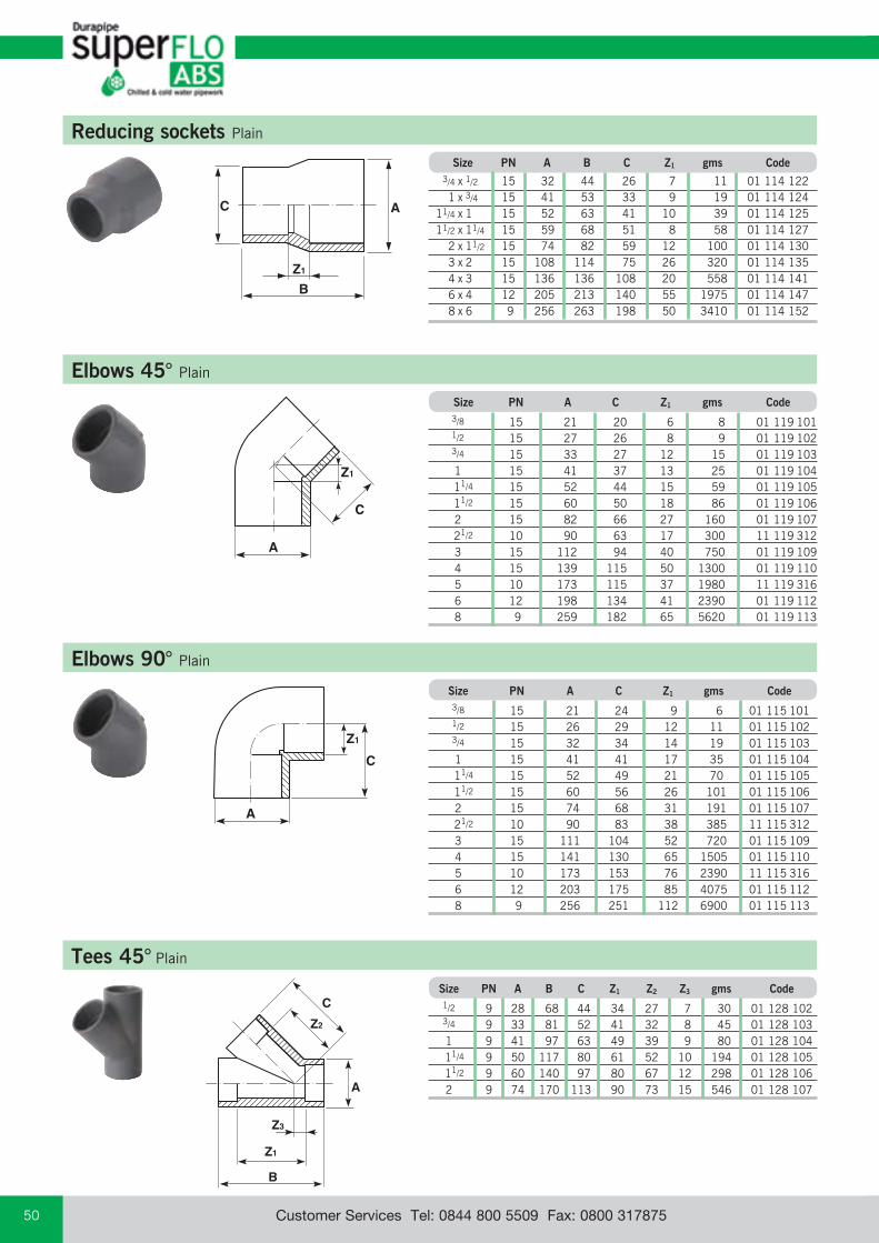
email: [email protected] web: www.durapipe.co.ukCustomer Services Tel: 0844 800 5509 Fax: 0800 31787550
Elbows 45° Plain
Elbows 90° Plain
Z1
A
C
Size PN A C Z1 gms Code
3/8 15 21 20 6 8 01 119 101 1/2 15 27 26 8 9 01 119 102 3/4 15 33 27 12 15 01 119 103 1 15 41 37 13 25 01 119 104 11/4 15 52 44 15 59 01 119 105 11/2 15 60 50 18 86 01 119 106 2 15 82 66 27 160 01 119 107 21/2 10 90 63 17 300 11 119 312 3 15 112 94 40 750 01 119 109 4 15 139 115 50 1300 01 119 110 5 10 173 115 37 1980 11 119 316 6 12 198 134 41 2390 01 119 112 8 9 259 182 65 5620 01 119 113
Size PN A C Z1 gms Code
3/8 15 21 24 9 6 01 115 101 1/2 15 26 29 12 11 01 115 102 3/4 15 32 34 14 19 01 115 103 1 15 41 41 17 35 01 115 104 11/4 15 52 49 21 70 01 115 105 11/2 15 60 56 26 101 01 115 106 2 15 74 68 31 191 01 115 107 21/2 10 90 83 38 385 11 115 312 3 15 111 104 52 720 01 115 109 4 15 141 130 65 1505 01 115 110 5 10 173 153 76 2390 11 115 316 6 12 203 175 85 4075 01 115 112 8 9 256 251 112 6900 01 115 113
A
Z1
C
B
A
Z1
C
Reducing sockets Plain
Size PN A B C Z1 gms Code
3/4 x 1/2 15 32 44 26 7 11 01 114 122 1 x 3/4 15 41 53 33 9 19 01 114 124 11/4 x 1 15 52 63 41 10 39 01 114 125 11/2 x 11/4 15 59 68 51 8 58 01 114 127 2 x 11/2 15 74 82 59 12 100 01 114 130 3 x 2 15 108 114 75 26 320 01 114 135 4 x 3 15 136 136 108 20 558 01 114 141 6 x 4 12 205 213 140 55 1975 01 114 147 8 x 6 9 256 263 198 50 3410 01 114 152
B
A
Z1
Z3
C
Z2
Tees 45° Plain
Size PN A B C Z1 Z2 Z3 gms Code
1/2 9 28 68 44 34 27 7 30 01 128 102 3/4 9 33 81 52 41 32 8 45 01 128 103 1 9 41 97 63 49 39 9 80 01 128 104 11/4 9 50 117 80 61 52 10 194 01 128 105 11/2 9 60 140 97 80 67 12 298 01 128 106 2 9 74 170 113 90 73 15 546 01 128 107

email: [email protected] web: www.durapipe.co.uk 51Customer Services Tel: 0844 800 5509 Fax: 0800 317875
C
Z1
BAZ1
Tees 90° Equal plain
Size PN A B C Z1 gms Code
3/8 15 21 49 25 10 7 01 122 101 1/2 15 26 58 29 11 13 01 122 102 3/4 15 32 69 34 15 23 01 122 103 1 15 41 83 42 19 43 01 122 104 11/4 15 52 101 50 23 92 01 122 105 11/2 15 59 113 53 25 133 01 122 106 2 15 74 137 70 31 249 01 122 107 21/2 10 90 172 87 36 510 11 122 312 3 15 113 204 105 44 926 01 122 109 4 15 143 244 121 54 1960 01 122 110 5 10 172 307 153 72 3200 11 122 316 6 12 205 355 175 88 4449 01 122 112 8 9 257 468 240 100 9600 01 122 113
C
Z1
D
A
Z3
Z2B
A
D
Z1
C
Z1B
Tees 90° Reducing
Tees 90° Swept plain
Size PN A B C D Z1 gms Code
3/4 x 1/2 15 32 64 32 26 17 22 01 124 122
1 x 1/2 15 40 70 36 26 17 40 01 124 123
1 x 3/4 15 40 76 38 32 20 41 01 124 124
Size PN A B C D Z1 Z2 Z3 gms Code
1 9 41 115 79 79 57 57 14 85 01 148 104
11/2 9 62 160 105 105 74 74 24 285 01 148 106
2 9 78 195 125 125 87 87 32 515 01 148 107
21/2 9 92 210 125 125 81 81 41 601 11 148 312
4 9 139 315 190 190 127 127 62 2080 01 148 110
Bends 221⁄2° Long radius
Size PN C E R gms Code
1 15 76 38 102 46 01 311 104 11/2 15 110 57 152 143 01 311 106 2 15 113 73 203 274 01 311 107 21/2 10 172 112 300 319 11 311 312 3 15 202 114 305 857 01 311 109 4 15 262 152 407 1886 01 311 110 5 10 322 210 560 2513 11 311 316 6 12 385 229 610 5154 01 311 112 8 9 503 305 812 8962 01 311 113
Tolerance on angle ±3°
R
C
E
Impe
rial
Fit
ting
s

email: [email protected] web: www.durapipe.co.ukCustomer Services Tel: 0844 800 5509 Fax: 0800 31787552
Bends 45° Long radius
C
R
E
Size PN C E R gms Code
1 15 75 37 102 51 01 310 104 11/2 15 113 55 152 156 01 310 106 2 15 152 73 203 322 01 310 107 21/2 10 300 113 300 429 11 310 312 3 15 238 121 305 1100 01 310 109 4 15 300 145 407 2290 01 310 110 5 10 512 280 560 5315 11 310 316 6 12 440 218 610 6290 01 310 112 8 9 592 280 812 11440 01 310 113
Tolerance on angle ±3°
Bends 90° Long radius
CR
E
Size PN C E R gms Code
3 15 403 98 305 1535 01 309 109 4 15 545 138 407 3440 01 309 110 5 10 840 280 560 6696 11 309 316 6 12 817 207 610 9430 01 309 112 8 9 1174 362 812 19070 01 309 113
Tolerance on angle ±3°
Bends 90° Short radius plain
Z1
C
A
Size PN A C Z1 gms Code
1/2 15 26 56 43 20 01 118 102
3/4 15 33 65 45 45 01 118 103
1 15 40 85 63 65 01 118 104
11/4 15 51 108 81 130 01 118 105
11/2 15 62 134 102 290 01 118 106
2 15 73 165 126 560 01 118 107
21/2 10 93 195 150 810 11 118 312
3 15 111 226 172 1445 01 118 109
4 15 140 280 216 2400 01 118 110
B
E
AZ1
pipecentre
line
Saddles Plain
Size PN A B E Z1 gms Code
2 x 11/4 15 60 136 48 33 90 01 126 129 3 x 11/2 15 76 140 60 46 158 01 126 134 4 x 2 15 95 140 74 58 230 01 126 140 6 x 2 15 71 154 73 86 225 01 126 146
Two saddles can be mounted diametrically opposite.
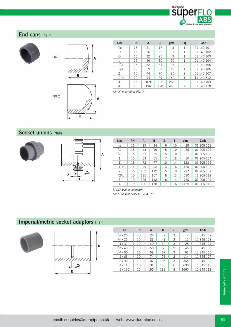
email: [email protected] web: www.durapipe.co.uk 53Customer Services Tel: 0844 800 5509 Fax: 0800 317875
End caps Plain
Socket unions Plain
B
Z2Z1
A
Size PN A B gms Fig Code
3/8 15 21 17 3 1 01 140 101 1/2 15 26 22 5 1 01 140 102 3/4 15 32 25 9 1 01 140 103 1 15 40 30 20 1 01 140 104 11/4 15 52 51 33 2 01 140 105 11/2 15 59 39 48 1 01 140 106 2 15 74 70 90 2 01 140 107 *21/2 10 94 59 180 1 11 149 312 3 15 109 97 268 2 01 140 109 4 15 136 120 465 2 01 140 110
*21/2” is rated at PN10.
Size PN A B Z1 Z2 gms Code
3/8 15 39 44 5 10 25 01 205 101 1/2 15 43 49 5 10 36 01 205 102 3/4 15 51 55 5 10 51 01 205 103 1 15 64 65 7 12 86 01 205 104 11/4 15 72 77 10 14 122 01 205 105 11/2 15 79 92 13 16 160 01 205 106 2 15 102 112 15 19 297 01 205 107 *21/2 10 135 107 8 13 610 11 205 312 3 9 155 113 6 4 750 01 205 109 4 9 180 138 7 6 1155 01 205 110
EPDM seal as standard.For FPM seal order 01 204 1**
FIG.1
FIG.2
BZ1
A
Imperial/metric socket adaptors Plain
Size PN A B Z1 gms Code
1/2 x 20 10 26 37 3 7 11 345 102 3/4 x 25 10 31 41 3 12 11 345 103 1 x 32 10 40 49 3 25 11 345 104 11/4 x 40 10 50 58 2 45 11 345 105 11/2 x 50 10 59 67 3 62 11 345 106 2 x 63 10 74 78 2 114 11 345 107 3 x 90 10 107 105 3 355 11 345 109 4 x 110 10 134 130 6 690 11 345 110 6 x 160 10 195 183 8 1660 11 345 112
Impe
rial
Fit
ting
s
B
A
B
A

email: [email protected] web: www.durapipe.co.ukCustomer Services Tel: 0844 800 5509 Fax: 0800 31787554
BZ1
Reducing bushes Plain female BSP thread
Size PN B Z1 gms Code
1/2 x 3/8 12 17 6 4 01 111 121 3/8 x 1/2 12 20 5 7 01 111 122 1 x 3/4 12 23 6 12 01 111 124
A
Z1
C
Z1
Elbows 90° Plain female BSP thread
Size PN A C Z1 gms Code
1/2 12 26 34 17 26 01 116 102 3/4 12 32 36 20 34 01 116 103 1 12 40 41 23 63 01 116 104 11/2 12 62 57 30 136 01 116 106 2 12 75 66 35 203 01 116 107
BC
Z1
A
Sockets Plain female BSP thread
Size PN A B C Z1 gms Code
1/2 12 27 38 17 4 8 01 101 102 3/4 12 33 44 20 2 14 01 101 103 1 12 42 51 23 5 30 01 101 104 11/4 12 52 55 22 4 46 01 101 105 11/2 12 60 61 26 2 65 01 101 106 2 12 75 70 29 2 114 01 101 107 3 12 110 107 52 3 378 01 101 109
Female threaded adaptors Plain spigot end/female BSP thread
Size PN A B Z1 gms Code
1/2 12 27 38 16 8 01 153 102 3/4 12 36 44 18 14 01 153 103 1 12 43 50 21 24 01 153 104 11/4 12 55 60 22 49 01 153 105 11/2 12 63 66 25 68 01 153 106 2 12 78 78 29 129 01 153 107Z1
B
A
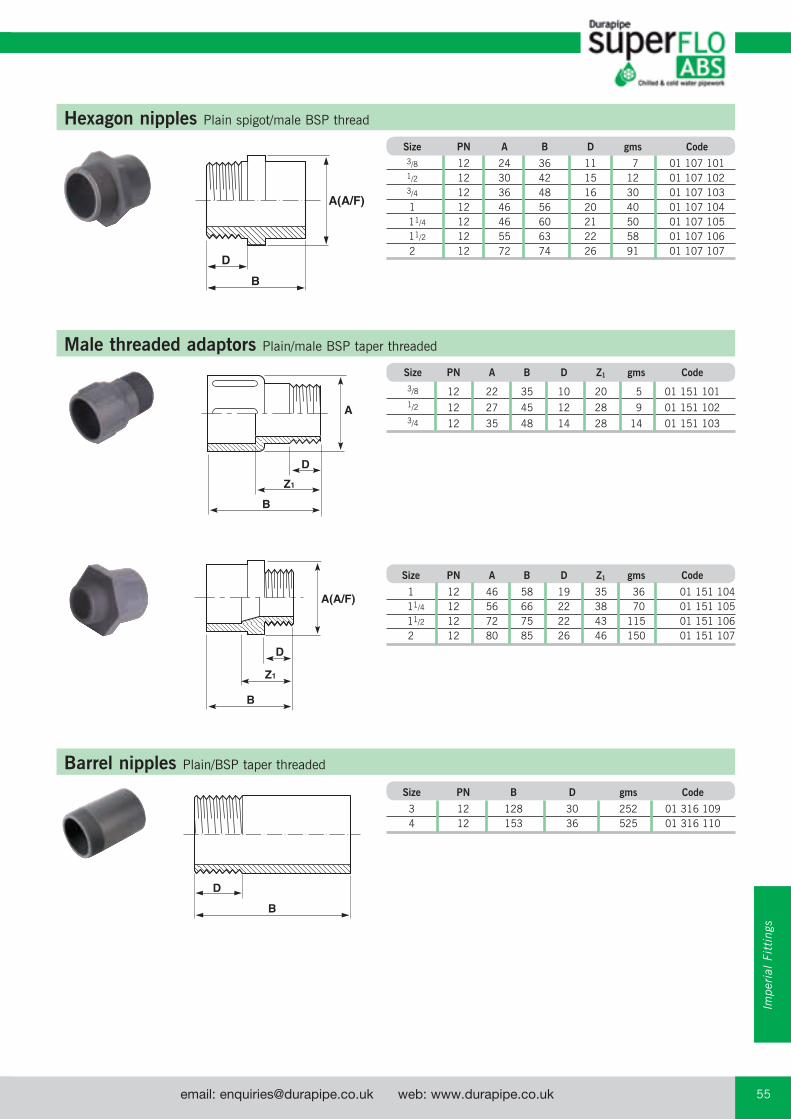
email: [email protected] web: www.durapipe.co.uk 55Customer Services Tel: 0844 800 5509 Fax: 0800 317875
Hexagon nipples Plain spigot/male BSP thread
Size PN A B D gms Code
3/8 12 24 36 11 7 01 107 101 1/2 12 30 42 15 12 01 107 102 3/4 12 36 48 16 30 01 107 103 1 12 46 56 20 40 01 107 104 11/4 12 46 60 21 50 01 107 105 11/2 12 55 63 22 58 01 107 106 2 12 72 74 26 91 01 107 107
B
D
A(A/F)
Male threaded adaptors Plain/male BSP taper threaded
Size PN A B D Z1 gms Code
3/8 12 22 35 10 20 5 01 151 101
1/2 12 27 45 12 28 9 01 151 102
3/4 12 35 48 14 28 14 01 151 103
Z1
B
A
D
B
Z1
D
A(A/F)
Size PN A B D Z1 gms Code
1 12 46 58 19 35 36 01 151 104 11/4 12 56 66 22 38 70 01 151 105 11/2 12 72 75 22 43 115 01 151 106 2 12 80 85 26 46 150 01 151 107
Barrel nipples Plain/BSP taper threaded
Size PN B D gms Code
3 12 128 30 252 01 316 109 4 12 153 36 525 01 316 110
B
D
Impe
rial
Fit
ting
s

email: [email protected] web: www.durapipe.co.ukCustomer Services Tel: 0844 800 5509 Fax: 0800 31787556
Z1
A(A/F)
B
Z2
B
Z1
A(A/F)
Composite unions Plain/brass, female BSP parallel thread
Composite unions Plain/brass, male BSP taper thread
Size PN A B Z1 Z2 gms Code
1/2 15 40 42 3 7 165 01 212 102 3/4 15 48 49 3 9 290 01 212 103 1 15 55 59 11 12 310 01 212 104 11/4 15 65 68 9 10 450 01 212 105 11/2 15 79 75 12 14 800 01 212 106 2 15 88 90 14 14 950 01 212 107
Fitted with brass retaining nut.Brass material to BS2872, WRAS approved.
Size PN A B Z1 gms Code
1/2 15 40 54 3 175 01 217 102 3/4 15 48 74 3 320 01 217 103 1 15 55 86 8 420 01 217 104 11/4 15 65 94 10 620 01 217 105 11/2 15 78 108 13 1000 01 217 106 2 15 88 129 15 1200 01 217 107
Fitted with brass retaining nut. Brass material to BS2872, WRAS approved.
B D
A(A/F)
C
E
Hose adaptors BSP taper threaded/hose tail
Size PN A B C D E gms Code
1/2 12 26 60 41 13 14 8 01 157 102 3/4 12 28 66 41 16 20 15 01 157 103 1 12 40 73 46 19 27 28 01 157 104
B
D
A(A/F) F C
Tank connectors Plain spigot/male BSP parallel thread
Size A B C D F gms Code
1/2 28 70 38 28 15 26 01 235 102
3/4 33 77 38 38 21 30 01 235 103
ALL Durapipe Brass Components are manufactured using DZR Brass.
ALL Durapipe Brass Components are manufactured using DZR Brass.
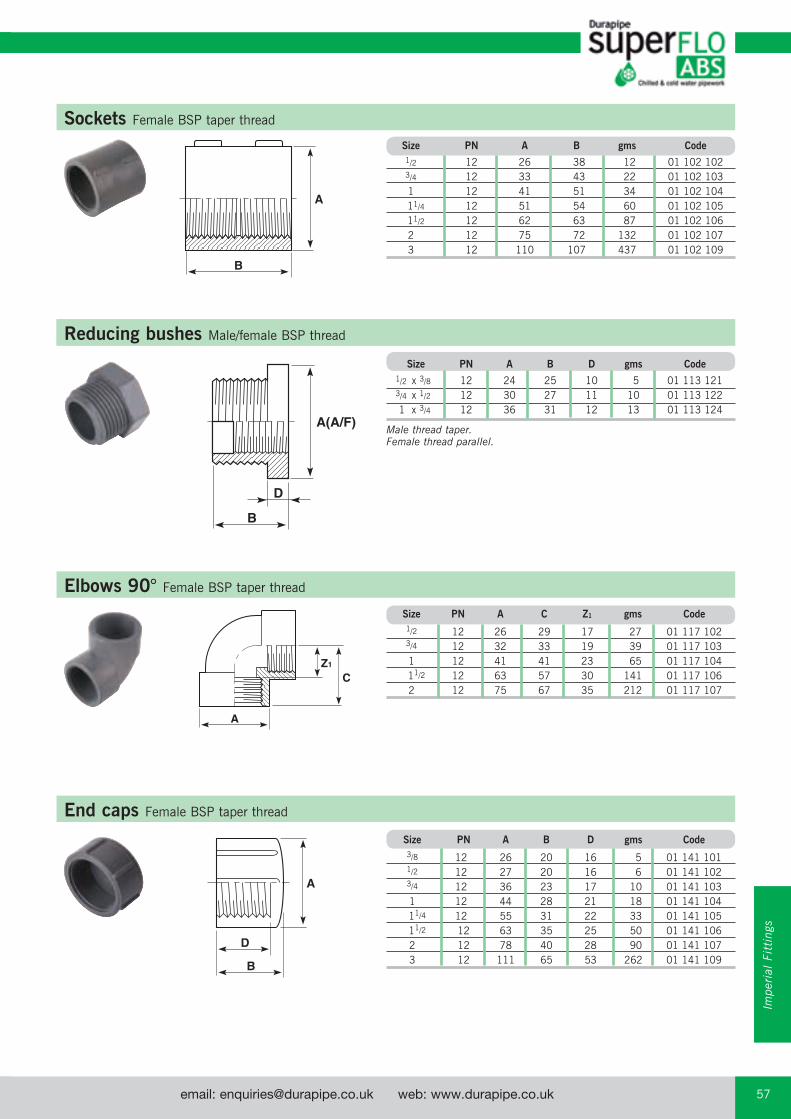
email: [email protected] web: www.durapipe.co.uk 57Customer Services Tel: 0844 800 5509 Fax: 0800 317875
B
A
Sockets Female BSP taper thread
Size PN A B gms Code
1/2 12 26 38 12 01 102 102 3/4 12 33 43 22 01 102 103 1 12 41 51 34 01 102 104 11/4 12 51 54 60 01 102 105 11/2 12 62 63 87 01 102 106 2 12 75 72 132 01 102 107 3 12 110 107 437 01 102 109
A
Z1
C
Elbows 90° Female BSP taper thread
Size PN A C Z1 gms Code
1/2 12 26 29 17 27 01 117 102 3/4 12 32 33 19 39 01 117 103 1 12 41 41 23 65 01 117 104 11/2 12 63 57 30 141 01 117 106 2 12 75 67 35 212 01 117 107
B
D
A(A/F)
Reducing bushes male/female BSP threadReducing bushes Male/female BSP thread
Size PN A B D gms Code
1/2 x 3/8 12 24 25 10 5 01 113 121 3/4 x 1/2 12 30 27 11 10 01 113 122 1 x 3/4 12 36 31 12 13 01 113 124
Male thread taper.Female thread parallel.
B
A
D
End caps Female BSP taper thread
Size PN A B D gms Code
3/8 12 26 20 16 5 01 141 101 1/2 12 27 20 16 6 01 141 102 3/4 12 36 23 17 10 01 141 103 1 12 44 28 21 18 01 141 104 11/4 12 55 31 22 33 01 141 105 11/2 12 63 35 25 50 01 141 106 2 12 78 40 28 90 01 141 107 3 12 111 65 53 262 01 141 109
Impe
rial
Fit
ting
s

email: [email protected] web: www.durapipe.co.ukCustomer Services Tel: 0844 800 5509 Fax: 0800 31787558
B
A(A/F)C
Back nuts Female BSP taper thread
Size PN A B C gms Code
3/8 12 25 11 29 5 01 159 101
1/2 12 28 13 38 8 01 159 102
3/4 12 33 13 38 15 01 159 103
1 12 45 16 54 18 01 159 104
11/4 12 50 18 58 19 01 159 105
11/2 12 60 19 69 31 01 159 106
2 12 79 21 91 65 01 159 107
Flanges stub Plain/serrated
Size PN A B D Z1 gms Code
2 15 96 40 14 3 90 01 135 107
21/2 10 106 49 10 4 150 11 135 312
3 15 127 57 18 6 200 01 135 109
4 15 159 69 20 6 350 01 135 110
5 15 180 83 14 7 680 11 135 316
6 12 213 104 24 11 805 01 135 112
8 9 269 132 26 14 2075 01 135 113
B
D
A(A/F)
Plugs Male BSP taper thread
Size PN A B D gms Code
3/8 12 11 19 10 3 01 155 101 1/2 12 13 23 14 5 01 155 102 3/4 12 14 28 15 8 01 155 103 1 12 17 30 17 12 01 155 104 11/4 12 22 35 22 30 01 155 105 11/2 12 27 38 22 36 01 155 106 2 12 37 45 26 50 01 155 107
B
D
A(A/F)
Hexagon nipples Male BSP taper thread
Size PN A B D gms Code
3/8 12 24 38 14 6 01 106 101
1/2 12 30 46 18 12 01 106 102
3/4 12 36 50 19 30 01 106 103
1 12 46 59 13 40 01 106 104
11/4 12 46 67 27 55 01 106 105
11/2 12 55 73 29 75 01 106 106
2 12 72 81 33 125 01 106 107
B
D
Z1
A
All Durapipe flanges are designed for use with Durapipe backing rings. Guarantees are null and void if used with incorrect backing ring.
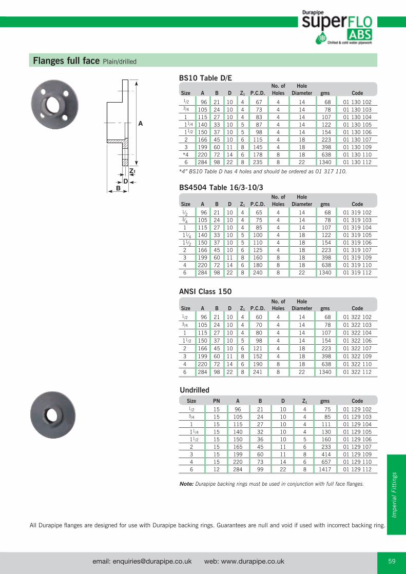
email: [email protected] web: www.durapipe.co.uk 59Customer Services Tel: 0844 800 5509 Fax: 0800 317875
Flanges full face Plain/drilled
BS10 Table D/E No. of Hole Size A B D Z1 P.C.D. Holes Diameter gms Code
1/2 96 21 10 4 67 4 14 68 01 130 102 3/4 105 24 10 4 73 4 14 78 01 130 103 1 115 27 10 4 83 4 14 107 01 130 104 11/4 140 33 10 5 87 4 14 122 01 130 105 11/2 150 37 10 5 98 4 14 154 01 130 106 2 166 45 10 6 115 4 18 223 01 130 107 3 199 60 11 8 145 4 18 398 01 130 109 *4 220 72 14 6 178 8 18 638 01 130 110 6 284 98 22 8 235 8 22 1340 01 130 112
*4” BS10 Table D has 4 holes and should be ordered as 01 317 110.
No. of Hole Size A B D Z1 P.C.D. Holes Diameter gms Code
1⁄2 96 21 10 4 65 4 14 68 01 319 102 3⁄4 105 24 10 4 75 4 14 78 01 319 103 1 115 27 10 4 85 4 14 107 01 319 104 11⁄4 140 33 10 5 100 4 18 122 01 319 105 11⁄2 150 37 10 5 110 4 18 154 01 319 106 2 166 45 10 6 125 4 18 223 01 319 107 3 199 60 11 8 160 8 18 398 01 319 109 4 220 72 14 6 180 8 18 638 01 319 110 6 284 98 22 8 240 8 22 1340 01 319 112
No. of Hole Size A B D Z1 P.C.D. Holes Diameter gms Code
1/2 96 21 10 4 60 4 14 68 01 322 102 3/4 105 24 10 4 70 4 14 78 01 322 103 1 115 27 10 4 80 4 14 107 01 322 104 11/2 150 37 10 5 98 4 14 154 01 322 106 2 166 45 10 6 121 4 18 223 01 322 107 3 199 60 11 8 152 4 18 398 01 322 109 4 220 72 14 6 190 8 18 638 01 322 110 6 284 98 22 8 241 8 22 1340 01 322 112
Size PN A B D Z1 gms Code
1/2 15 96 21 10 4 75 01 129 102 3/4 15 105 24 10 4 85 01 129 103 1 15 115 27 10 4 111 01 129 104 11/4 15 140 32 10 4 130 01 129 105 11/2 15 150 36 10 5 160 01 129 106 2 15 165 45 11 6 233 01 129 107 3 15 199 60 11 8 414 01 129 109 4 15 220 73 14 6 657 01 129 110 6 12 284 99 22 8 1417 01 129 112
Note: Durapipe backing rings must be used in conjunction with full face flanges.
Undrilled
A
Z1
D B
All Durapipe flanges are designed for use with Durapipe backing rings. Guarantees are null and void if used with incorrect backing ring.
BS4504 Table 16/3-10/3
ANSI Class 150
Impe
rial
Fit
ting
s
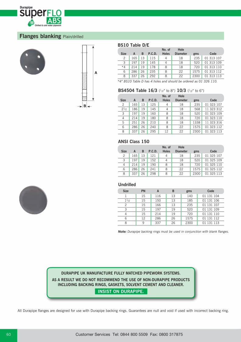
email: [email protected] web: www.durapipe.co.ukCustomer Services Tel: 0844 800 5509 Fax: 0800 31787560
ANSI Class 150 No. of Hole Size A B P.C.D. Holes Diameter gms Code 2 165 13 121 4 18 235 01 325 107 3 197 19 152 4 18 520 01 325 109 4 214 19 190 8 18 720 01 325 110 6 286 26 241 8 22 1575 01 325 112 8 337 26 298 8 22 2300 01 325 113
B
A
BS10 Table D/E No. of Hole Size A B P.C.D. Holes Diameter gms Code 2 165 13 115 4 18 235 01 313 107 3 197 19 145 4 18 520 01 313 109 *4 214 19 178 8 18 720 01 313 110 6 286 26 235 8 22 1575 01 313 112 8 337 26 292 8 22 2300 01 313 113
*4” BS10 Table D has 4 holes and should be ordered as 01 326 110.
Flanges blanking Plain/drilled
Size PN A B gms Code
1 15 116 13 140 01 131 104 11/2 15 150 13 185 01 131 106 2 15 166 13 235 01 131 107 3 15 197 19 520 01 131 109 4 15 214 19 720 01 131 110 6 12 286 26 1575 01 131 112 8 9 337 26 2300 01 131 113
Note: Durapipe backing rings must be used in conjunction with blank flanges.
Undrilled
BS4504 Table 16/3 (1/2” to 8”) 10/3 (1/2” to 6”) No. of Hole Size A B P.C.D. Holes Diameter gms Code 2 165 13 125 4 18 235 01 323 107 21/2 186 19 145 4 18 568 11 323 312 3 197 19 160 8 18 520 01 323 109 4 214 19 180 8 18 720 01 323 110 5 251 26 210 8 18 1338 11 323 316 6 286 26 240 8 22 1575 01 323 112 8 337 26 295 12 22 2300 01 323 113
All Durapipe flanges are designed for use with Durapipe backing rings. Guarantees are null and void if used with incorrect backing ring.
DURAPIPE UK MANUFACTURE FULLY MATCHED PIPEWORK SYSTEMS.
AS A RESULT WE DO NOT RECOMMEND THE USE OF NON-DURAPIPE PRODUCTS INCLUDING BACKING RINGS, GASKETS, SOLVENT CEMENT AND CLEANER.
INSIST ON DURAPIPE.
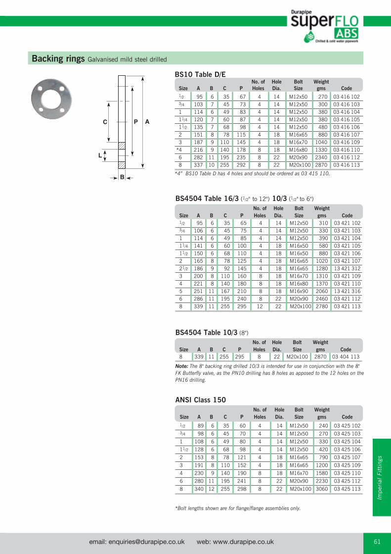
email: [email protected] web: www.durapipe.co.uk 61Customer Services Tel: 0844 800 5509 Fax: 0800 317875
B
AC P
L
Backing rings Galvanised mild steel drilled
BS10 Table D/E No. of Hole Bolt Weight Size A B C P Holes Dia. Size gms Code 1⁄2 95 6 35 67 4 14 M12x50 270 03 416 102 3/4 103 7 45 73 4 14 M12x50 300 03 416 103 1 114 6 49 83 4 14 M12x50 380 03 416 104 11/4 120 7 60 87 4 14 M12x50 380 03 416 105 11⁄2 135 7 68 98 4 14 M12x50 480 03 416 106 2 151 8 78 115 4 18 M16x65 880 03 416 107 3 187 9 110 145 4 18 M16x70 1040 03 416 109 *4 216 9 140 178 8 18 M16x80 1330 03 416 110 6 282 11 195 235 8 22 M20x90 2340 03 416 112 8 337 10 255 292 8 22 M20x100 2870 03 416 113
*4” BS10 Table D has 4 holes and should be ordered as 03 415 110.
BS4504 Table 16/3 (1/2" to 12") 10/3 (1/2" to 6")
No. of Hole Bolt Weight Size A B C P Holes Dia. Size gms Code 1/2 95 6 35 65 4 14 M12x50 310 03 421 102 3/4 106 6 45 75 4 14 M12x50 330 03 421 103 1 114 6 49 85 4 14 M12x50 390 03 421 104 11/4 141 6 60 100 4 18 M16x50 580 03 421 105 11/2 150 6 68 110 4 18 M16x50 880 03 421 106 2 165 8 78 125 4 18 M16x65 1020 03 421 107 21/2 186 9 92 145 4 18 M16x65 1280 13 421 312 3 200 8 110 160 8 18 M16x70 1310 03 421 109 4 221 8 140 180 8 18 M16x80 1370 03 421 110 5 251 11 167 210 8 18 M16x90 2060 13 421 316 6 286 11 195 240 8 22 M20x90 2460 03 421 112 8 339 11 255 295 12 22 M20x100 2780 03 421 113
BS4504 Table 10/3 (8")
No. of Hole Bolt Weight Size A B C P Holes Dia. Size gms Code 8 339 11 255 295 8 22 M20x100 2870 03 404 113
ANSI Class 150 No. of Hole Bolt Weight Size A B C P Holes Dia. Size gms Code
1/2 89 6 35 60 4 14 M12x50 240 03 425 102
3/4 98 6 45 70 4 14 M12x50 270 03 425 103
1 108 6 49 80 4 14 M12x50 330 03 425 104
11/2 128 6 68 98 4 14 M12x50 420 03 425 106
2 153 8 78 121 4 18 M16x65 790 03 425 107
3 191 8 110 152 4 18 M16x65 1200 03 425 109
4 230 9 140 190 8 18 M16x70 1580 03 425 110
6 280 11 195 241 8 22 M20x90 2230 03 425 112
8 340 12 255 298 8 22 M20x100 3060 03 425 113
Note: The 8" backing ring drilled 10/3 is intended for use in conjunction with the 8" FK Butterfly valve, as the PN10 drilling has 8 holes as apposed to the 12 holes on the PN16 drilling.
*Bolt lengths shown are for flange/flange assemblies only.
Impe
rial
Fit
ting
s

email: [email protected] web: www.durapipe.co.ukCustomer Services Tel: 0844 800 5509 Fax: 0800 31787562
Gaskets full face Drilled EPDM
B
A
No. of Hole Size A B P.C.D. Holes Diameter gms Code
1/2 95 3.0 67 4 14 31 03 410 102 3/4 112 3.0 73 4 14 37 03 410 103 1 115 3.0 83 4 14 37 03 410 104 11/4 121 3.0 87 4 14 41 03 410 105 11/2 133 3.0 98 4 14 55 03 410 106 2 153 3.0 115 4 18 56 03 410 107 3 184 3.0 145 4 18 98 03 410 109 *4 216 3.2 178 8 18 112 03 410 110 6 250 3.1 235 8 22 160 03 410 112
*4” BS10 Table D has 4 holes and should be ordered as 03 409 11
No. of Hole Size A B P.C.D. Holes Diameter gms Code
1/2 95 3.0 65 4 14 31 03 408 102 3/4 112 3.0 75 4 14 37 03 408 103 1 115 3.0 85 4 14 37 03 408 104 11/4 121 3.0 100 4 18 41 03 408 105 11/2 133 3.0 110 4 18 55 03 408 106 2 153 3.0 125 4 18 56 03 408 107 3 184 3.0 160 8 18 98 03 408 109 4 216 3.2 180 8 18 112 03 408 110 6 280 3.1 240 8 22 160 03 408 112
No. of Hole Size A B P.C.D. Holes Diameter gms Code 1/2 95 3.0 60 4 14 31 03 426 102 3/4 112 3.0 70 4 14 37 03 426 103 1 115 3.0 80 4 14 37 03 426 104 11/2 133 3.0 98 4 14 55 03 426 106 2 153 3.0 121 4 18 56 03 426 107 3 184 3.0 152 4 18 98 03 426 109 4 216 3.2 190 8 18 112 03 426 110 6 280 3.1 241 8 22 160 03 426 112
B
A
Gaskets flat Stub flange EPDM
Size A B gms Code
2 97 3.0 21 03 431 107 21/2 106 3.0 22 13 411 312 3 128 3.0 23 03 431 109 4 160 3.9 36 03 431 110 5 180 4.0 60 13 411 316 6 214 3.9 74 03 431 112 8 269 4.0 92 03 431 113
BS10 Table D/E
BS4504 Table 16/3-10/3
ANSI Class 150
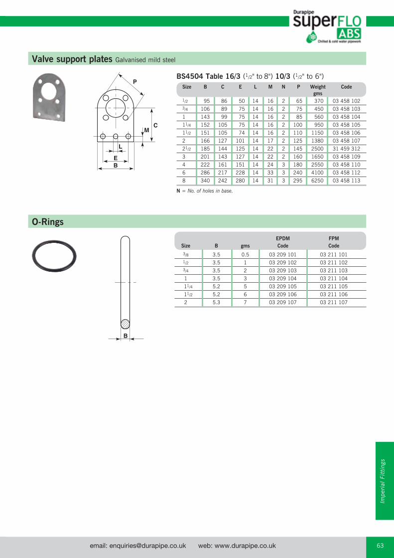
email: [email protected] web: www.durapipe.co.uk 63Customer Services Tel: 0844 800 5509 Fax: 0800 317875
C
P
M
L
EB
BS4504 Table 16/3 (1/2" to 8") 10/3 (1/2" to 6") Size B C E L M N P Weight Code gms 1/2 95 86 50 14 16 2 65 370 03 458 102
3/4 106 89 75 14 16 2 75 450 03 458 103
1 143 99 75 14 16 2 85 560 03 458 104
11/4 152 105 75 14 16 2 100 950 03 458 105
11/2 151 105 74 14 16 2 110 1150 03 458 106
2 166 127 101 14 17 2 125 1380 03 458 107
21/2 185 144 125 14 22 2 145 2500 31 459 312
3 201 143 127 14 22 2 160 1650 03 458 109
4 222 161 151 14 24 3 180 2550 03 458 110
6 286 217 228 14 33 3 240 4100 03 458 112
8 340 242 280 14 31 3 295 6250 03 458 113
N = No. of holes in base.
Valve support plates Galvanised mild steel
B
O-Rings
EPDM FPM Size B gms Code Code
3/8 3.5 0.5 03 209 101 03 211 101
1/2 3.5 1 03 209 102 03 211 102
3/4 3.5 2 03 209 103 03 211 103
1 3.5 3 03 209 104 03 211 104
11/4 5.2 5 03 209 105 03 211 105
11/2 5.2 6 03 209 106 03 211 106
2 5.3 7 03 209 107 03 211 107
Impe
rial
Fit
ting
s

email: [email protected] web: www.durapipe.co.ukCustomer Services Tel: 0844 800 5509 Fax: 0800 31787564
VKD Double union ball valves Manual – EPDM seals
Options: FPM seals (plain ends) order H0 DKB*** FPM seals (threaded ends) order H0 DKB***
Manual valves can be supplied with locking kits - further information is available from our Valve Department.
d DN PN L Z H E B C gms Code
3/8 10 16 14.5 74 103 55 49 66 160 H0 DKA 101
1/2 15 16 16.5 70 103 55 49 66 160 H0 DKA 102
3/4 20 16 19 77 115 66 59 75 265 H0 DKA 103
1 25 16 22.5 83 128 75 66 85 345 H0 DKA 104
11/4 32 16 26 94 146 87 75 97 550 H0 DKA 105
11/2 40 16 30 104 164 100 87 110 730 H0 DKA 106
2 50 16 36 127 199 122 101 134 1280 H0 DKA 107
Valves
d DN PN Z L H H1 E B B1 C C1 gms Code
21/2 65 16 147 44 235 133 164 164 87 225 175 3725 H0 DKA 312
3 80 16 168 51 270 149 203 177 105 327 272 5700 H0 DKA 109
4 100 16 186 61 308 167 238 195 129 385 330 8660 H0 DKA 110
Options: FPM seals (plain ends) order H0 DKB***
TKD 3-way ball valves Manual – EPDM seals
Options: FPM seals (plain ends) order H0 TTB*** FPM seals (threaded ends) order H0 TTB***
Manual valves can be supplied with locking kits - further information is available from our Valve Department.
d DN PN H Z C C1 B B1 gms Code
1/2 15 16 125 95 67 40 54 29 235 H0 TTA 102
3/4 20 16 146 114 85 49 65 34.5 415 H0 TTA 103
1 25 16 166 129 85 49 65.9 39 570 H0 TTA 104
11/4 32 16 195.5 151 108 64 82.5 46 895 H0 TTA 105
11/2 40 16 211 166 108 64 89 52 1250 H0 TTA 106
2 50 16 253.5 199 134 76 108 62 2225 H0 TTA 107
d DN PN H Z C C1 B B1 gms Code
1/2 15 16 125 95 67 40 54 29 235 H0 LTA 102
3/4 20 16 146 114 85 49 65 34.5 415 H0 LTA 103
1 25 16 166 129 85 49 65.9 39 570 H0 LTA 104
11/4 32 16 195.5 151 108 64 82.5 46 895 H0 LTA 105
11/2 40 16 211 166 108 64 89 52 1250 H0 LTA 106
2 50 16 253.5 199 134 76 108 62 2225 H0 LTA 107
Options: FPM seals (plain ends) order H0 LTB***
T-Port design
L-Port design
VKD & TKD ball valves can be supplied electrically or pneumatically actuated.
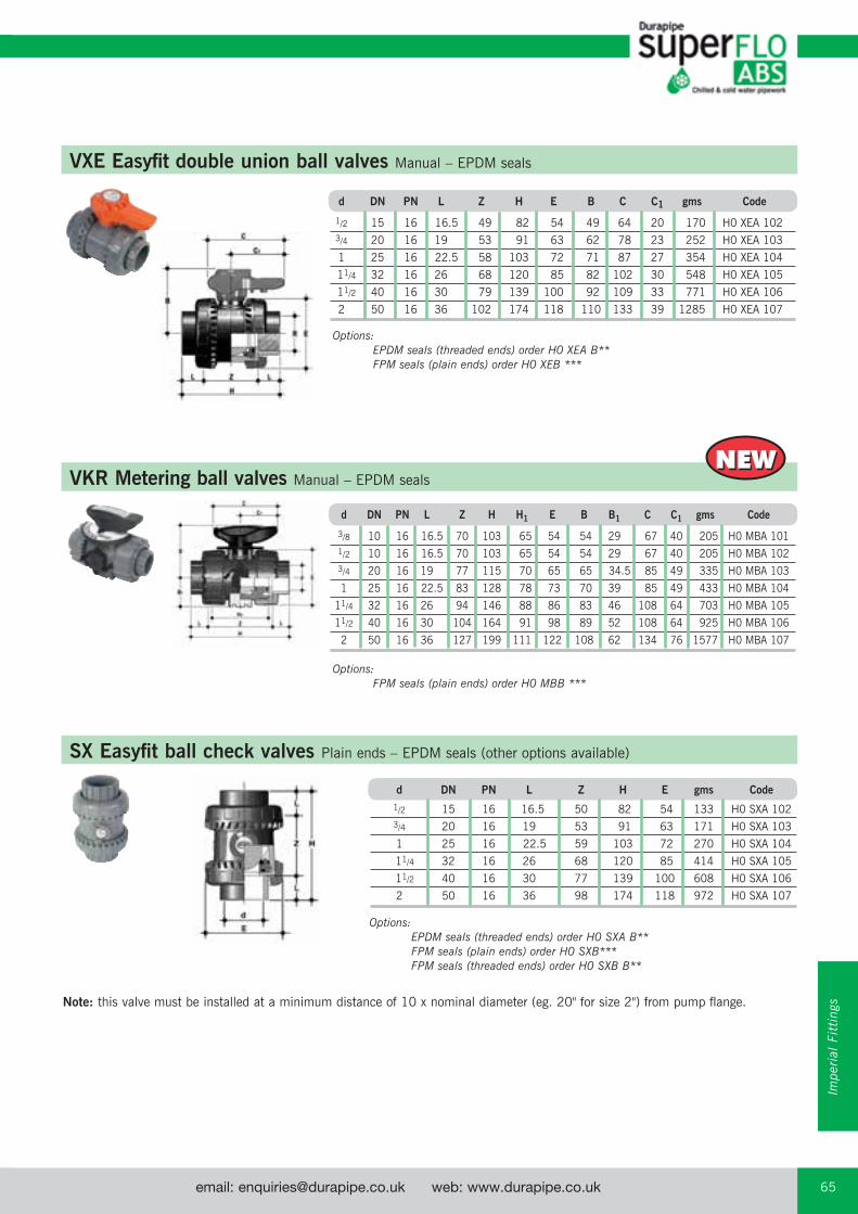
email: [email protected] web: www.durapipe.co.uk 65Customer Services Tel: 0844 800 5509 Fax: 0800 317875
SX Easyfit ball check valves Plain ends – EPDM seals (other options available)
d DN PN L Z H E gms Code
1/2 15 16 16.5 50 82 54 133 H0 SXA 102
3/4 20 16 19 53 91 63 171 H0 SXA 103
1 25 16 22.5 59 103 72 270 H0 SXA 104
11/4 32 16 26 68 120 85 414 H0 SXA 105
11/2 40 16 30 77 139 100 608 H0 SXA 106
2 50 16 36 98 174 118 972 H0 SXA 107
Options: EPDM seals (threaded ends) order H0 SXA B** FPM seals (plain ends) order H0 SXB*** FPM seals (threaded ends) order H0 SXB B**
Options: EPDM seals (threaded ends) order H0 XEA B** FPM seals (plain ends) order H0 XEB ***
Note: this valve must be installed at a minimum distance of 10 x nominal diameter (eg. 20" for size 2") from pump flange.
VXE Easyfit double union ball valves Manual – EPDM seals
VKR Metering ball valves Manual – EPDM seals
d DN PN L Z H E B C C1 gms Code
1/2 15 16 16.5 49 82 54 49 64 20 170 H0 XEA 102
3/4 20 16 19 53 91 63 62 78 23 252 H0 XEA 103
1 25 16 22.5 58 103 72 71 87 27 354 H0 XEA 104
11/4 32 16 26 68 120 85 82 102 30 548 H0 XEA 105
11/2 40 16 30 79 139 100 92 109 33 771 H0 XEA 106
2 50 16 36 102 174 118 110 133 39 1285 H0 XEA 107
NEWNEW
d DN PN L Z H H1 E B B1 C C1 gms Code
3/8 10 16 16.5 70 103 65 54 54 29 67 40 205 H0 MBA 101
1/2 10 16 16.5 70 103 65 54 54 29 67 40 205 H0 MBA 102
3/4 20 16 19 77 115 70 65 65 34.5 85 49 335 H0 MBA 103
1 25 16 22.5 83 128 78 73 70 39 85 49 433 H0 MBA 104
11/4 32 16 26 94 146 88 86 83 46 108 64 703 H0 MBA 105
11/2 40 16 30 104 164 91 98 89 52 108 64 925 H0 MBA 106
2 50 16 36 127 199 111 122 108 62 134 76 1577 H0 MBA 107
Impe
rial
Fit
ting
s
Options: FPM seals (plain ends) order H0 MBB ***
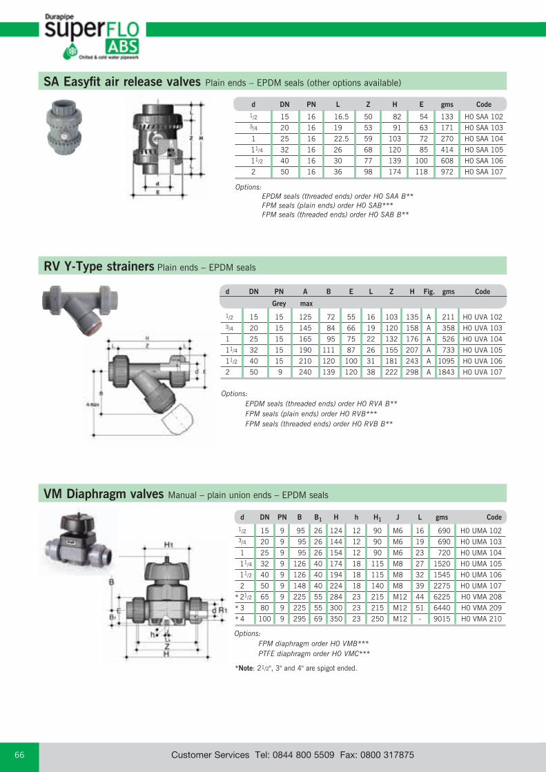
email: [email protected] web: www.durapipe.co.ukCustomer Services Tel: 0844 800 5509 Fax: 0800 31787566
RV Y-Type strainers Plain ends – EPDM seals
Options: EPDM seals (threaded ends) order H0 RVA B** FPM seals (plain ends) order H0 RVB*** FPM seals (threaded ends) order H0 RVB B**
d DN PN A B E L Z H Fig. gms Code
Grey max
1/2 15 15 125 72 55 16 103 135 A 211 H0 UVA 102
3/4 20 15 145 84 66 19 120 158 A 358 H0 UVA 103
1 25 15 165 95 75 22 132 176 A 526 H0 UVA 104
11/4 32 15 190 111 87 26 155 207 A 733 H0 UVA 105
11/2 40 15 210 120 100 31 181 243 A 1095 H0 UVA 106
2 50 9 240 139 120 38 222 298 A 1843 H0 UVA 107
VM Diaphragm valves Manual – plain union ends – EPDM seals
Options: FPM diaphragm order H0 VMB*** PTFE diaphragm order H0 VMC***
d DN PN B B1 H h H1 J L gms Code
1/2 15 9 95 26 124 12 90 M6 16 690 H0 UMA 102
3/4 20 9 95 26 144 12 90 M6 19 690 H0 UMA 103
1 25 9 95 26 154 12 90 M6 23 720 H0 UMA 104
11/4 32 9 126 40 174 18 115 M8 27 1520 H0 UMA 105
11/2 40 9 126 40 194 18 115 M8 32 1545 H0 UMA 106
2 50 9 148 40 224 18 140 M8 39 2275 H0 UMA 107
21/2 65 9 225 55 284 23 215 M12 44 6225 H0 VMA 208
3 80 9 225 55 300 23 215 M12 51 6440 H0 VMA 209
4 100 9 295 69 350 23 250 M12 - 9015 H0 VMA 210
*
*
*
*Note: 21/2", 3" and 4" are spigot ended.
d DN PN L Z H E gms Code
1/2 15 16 16.5 50 82 54 133 H0 SAA 102
3/4 20 16 19 53 91 63 171 H0 SAA 103
1 25 16 22.5 59 103 72 270 H0 SAA 104
11/4 32 16 26 68 120 85 414 H0 SAA 105
11/2 40 16 30 77 139 100 608 H0 SAA 106
2 50 16 36 98 174 118 972 H0 SAA 107
SA Easyfit air release valves Plain ends – EPDM seals (other options available)
Options: EPDM seals (threaded ends) order H0 SAA B** FPM seals (plain ends) order H0 SAB*** FPM seals (threaded ends) order H0 SAB B**

email: [email protected] web: www.durapipe.co.uk 67Customer Services Tel: 0844 800 5509 Fax: 0800 317875
PR Pressure relief valves EPDM seals
C
ZEG
B
A
D
F
Size PN Z A B C D E F G gms Code
1⁄2 10 92 143 20.5 35 124 M6 25 12 700 H0 PRA 202
3⁄4 10 106 143 20.5 35 144 M6 25 12 700 H0 PRA 203
1 10 108 143 25.0 35 154 M6 25 12 700 H0 PRA 204
11⁄4 9 120 204 36.0 50 174 M8 44.5 16 1500 H0 PRA 205
11⁄2 9 130 204 39.5 50 194 M8 44.5 16 1500 H0 PRA 206
2 9 146 219 49.0 50 224 M8 44.5 16 2400 H0 PRA 207
Options: FPM seals order H0 PRB***
Size DN PN B2 B3 C C1 Z gms U Code
11⁄2 40 15 60 137 175 100 33 900 4 H0 FKA 106
2 50 15 70 143 175 100 43 1080 4 H0 FKA 107
21⁄2 65 9 80 164 272 110 46 1470 4 H0 FKA 108
3 80 9 93 178 272 110 49 1870 8 H0 FKA 109
4 100 9 107 192 272 110 56 2220 8 H0 FKA 110
5 125 9 120 212 330 110 64 3100 8 H0 FKA 111
6 150 9 134 225 330 110 70 3850 8 H0 FKA 112
8 200 9 161 272 420 122 71 6750 8 H0 FKA 113
FK Butterfly valves Glass reinforced polypropylene with ABS disc and EPDM seals
Size DN PN B2 B5 B6 G G1 G2 G3 Z gms U Code
21⁄2 65 9 80 174 146 48 135 39 125 46 2400 4 HV FKA 108
3 80 9 93 188 160 48 135 39 125 49 2800 8 HV FKA 109
4 100 9 107 202 174 48 135 39 125 56 3150 8 HV FKA 110
5 125 9 120 222 194 48 144 39 200 64 4450 8 HV FKA 111
6 150 9 134 235 207 48 144 39 200 70 5200 8 HV FKA 112
8 200 9 161 287 256 65 204 60 200 71 9300 8 HV FKA 113
10 250 10 210 317 281 88 236 76 250 114 18600 12 HV FKA 114
12 300 8 245 374 338 88 236 76 250 114 25600 12 HV FKA 115
lever operated
with gear box
Options: FPM seals order HV FKB***
Options: FPM seals order H0 FKB***
U = No. of holes
U = No. of holes
Note: Lugged versions available to special order. Please refer to our Valve Department for further details.
Valves can be supplied as electrically or pneumatically actuated. For further details contact our Valve department on 01543 272424.
Impe
rial
Fit
ting
s

email: [email protected] web: www.durapipe.co.ukCustomer Services Tel: 0844 800 5509 Fax: 0800 31787568
BG
C
A
D
G E
C
F
Cobra pipe clips Polypropylene
Size A B C D G Bolt/Screw size gms Code
3/8 – 35 25 19 16 M.4/3BA/No 8 7 13 434 305 1/2 – 35 30 14 16 M.5/1BA/No 10 8 13 434 306 3/4 – 35 35 16 17 M.5/1BA/No 10 11 13 434 307 1 – 40 40 17 17 M.5/1BA/No 10 14 13 434 308 11/4 75 45 45 20 20 M.5/1BA/No 10 21 13 434 309 11/2 85 50 50 22 21 M.6/0BA/No 10 30 13 434 310 2 102 60 60 19 21 M.6/0BA/No 10 42 13 434 311 21/2 122 70 70 27 31 M.8 94 13 434 312 3 148 80 90 39 31 M.8 121 13 434 313 4 171 90 96 36 35 M.8 185 13 434 314 5 211 156 132 40 40 M.8 252 13 434 316 6 243 170 150 40 40 M.8 330 13 434 317
Saddle clips Polypropylene
Size C E F G Bolt/Screw size gms Code
3/8 13 37 – 14 M.4/3BA/No 8 3 03 455 101 1/2 18 41 – 14 M.4/3BA/No 8 4 03 455 102 3/4 21 45 – 16 M.5/2BA/No 10 6 03 455 103 1 23 56 – 16 M.5/2BA/No 10 7 03 455 104 11/4 29 65 – 16 M.5/2BA/No 10 11 03 455 105 11/2 34 67 – 16 M.5/2BA/No 10 12 03 455 106 2 38 87 – 22 M.6/0BA/No 12 25 03 455 107 3 50 122 8 34 M.10/3⁄8UNC 45 03 455 109 4 65 156 13 38 M.10/3⁄8UNC 70 03 455 110
One-step solvent cement
Only Durapipe ABS solvent cement and Durapipe Eco-cleaner should be used for jointing of Durapipe ABS pipework systems.
Eco-cleaner Litres gms Code
0.5 500 03 457 395
Only Durapipe ABS solvent cement and Durapipe Eco-cleaner should be used for jointing of Durapipe ABS pipework systems.
Litres gms Code
0.5 550 03 461 395
1.0 1100 03 461 396
Accessories
Clips of size 11/4" and above are fitted with retaining strap. Bolts/screws not supplied.
Backing plate shown dotted supplied with 3" and 4" only. Bolts/screws not supplied. Bolt holes in 3" and 4" clips are not countersunk.
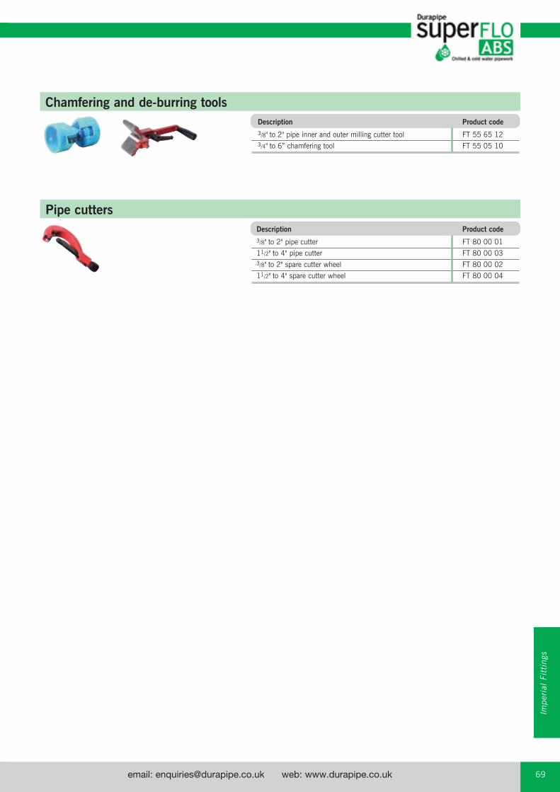
email: [email protected] web: www.durapipe.co.uk 69Customer Services Tel: 0844 800 5509 Fax: 0800 317875
Chamfering and de-burring tools
Pipe cutters
Description Product code
3/8" to 2" pipe inner and outer milling cutter tool FT 55 65 12
3/4" to 6” chamfering tool FT 55 05 10
Description Product code
3/8" to 2" pipe cutter FT 80 00 01
11/2" to 4" pipe cutter FT 80 00 03
3/8" to 2" spare cutter wheel FT 80 00 02
11/2" to 4" spare cutter wheel FT 80 00 04
Impe
rial
Fit
ting
s
email: [email protected] web: www.durapipe.co.ukCustomer Services Tel: 0844 800 5509 Fax: 0800 31787570
Product SpecificationMETRIC RANGEDURAPIPE SuperFLO ABS PIPES
KIWA 49, ISO 161/1, and ISO DIS 15493 (where applicable). Pressure rating PN10 at 20°C up to 250 mm. PN8 at 20°C for 315 mm.
DURAPIPE SuperFLO ABS FITTINGSKIWA 549, ISO 727 and ISO DIS 15493 (where applicable). Pressure rating PN10 at 20°C up to 250 mm. PN8 at 20°C for 315 mm.
MATCHED SYSTEMThe ABS products shall be from a single manufacturer to ensure complete integrity, quality and compatibility between pipes, fittings and valves. Manufacturer’s warranties may be compromised if a system is installed with materials from various manufacturers. Where this is not possible then any alternative products should be confirmed as being at least equivalent to that which is normally supplied.
QUALITY SYSTEMPipes, fittings and valves shall be manufactured in an environment which operates a Quality Assurance System assessed to ISO 9001.
ENVIRONMENTAL SYSTEMThe manufacturer of pipes, fittings, and valves shall be able to demonstrate compliance with applicable environmental legislation and products shall be manufactured in an environment where documented performance reviews are undertaken and an Environmental Management System is successfully assessed to ISO 14001.The manufacturer shall offer ABS solvent cements and cleaners, specially formulated to minimise any adverse effects on the environment during installation of the ABS system.
THIRD PARTY APPROVALSThe manufacturer shall have the following Third Party Approvals:
WRAS Water Regulations Advisory Scheme1505040 - Durapipe SuperFLO ABS Metric Pipe and Fittings 1509035 - Durapipe SuperFLO ABS VKD and VKR Ball Valves
APPROVAL FOR USE IN CONTACT WITH DRINKING WATERAll ABS pipes, fittings and solvent cement shall be listed in the Water Fittings and Materials Directory to show compliance with the requirements of the United Kingdom Water Regulations Advisory Service.Copies of certification of compliance with these approvals are available for inspection.
MARINE APPROVALSAmerican Bureau of ShippingBureau VeritasGermanischer LloydDet Norske VeritasLloyds register UKRINA (Royal Institution of Naval Architects)Russian Marine register
DESIGN LIFEPipes, fittings and valves shall be designed to operate continuously for 50 years at their maximum rated pressure at a working temperature of 20°C.Process Control Testing must be carried out during manufacture and documented on each and every production batch.Fittings and Pipes will be subjected to a pressure test of 3.2 x maximum recommended working pressure for 1 hour at 20°C during 1st and 2nd hours of production, then every 6 hours for fittings and 8 hours for pipes.Pipes are in addition to be impact tested after conditioning at 0°C for 1 hour.Fittings are in addition to be subject to stress relief testing at 150°C.Pipes and fittings shall undergo dimensional, marking, and visual inspection at the frequency outlined above.
CHEMICAL SUITABILITYThe manufacturer shall publish detailed chemical resistance data to enable the suitability of the ABS material, seals, and gaskets to be determined by designers and specifiers.The manufacturer shall also employ a qualified and experienced Chemist and provide a free-of-charge advisory service for assessing the suitability of its ABS material, seals, and gaskets.
INSTALLATION SPECIFICATIONThe installation must be carried out by competent persons. The contractor shall be required to provide technical documentation relating to the manufacturer’s recommended Installation procedures. The manufacturer shall publish Installation recommendations, and shall also provide a free-of-charge training service for designers and installers, with appropriate written confirmation of attendance.
DURAPIPE SuperFLO ABS BALL VALVESTrue union design, end load resistant with full pressure and shock resistant anti blow out device which conforms to design and endurance testing requirements of BS 5392 Part 1 1976, and DIN 3230 Part 3 Leak Rate One (Water and Air).
The following testing will have been successfully completed:
Drop Tight and Bubble Tight testHydrostatic Shell Test 1.5 x maximum working pressureSeat Test 1.1 x maximum working pressure
PRESSURE RATING16mm to 63mm - PN 16 at 20°C (VKD series), PN10 (VXE series)75mm to 110mm - PN16 at 20°C (VKD series)
SEATS AND SEALSSeats: PTFE material fitted with O-Ring compensators Seals: Standard size O-Ring type for ease of replacement Available in EPDM or FPM materials
END CONNECTIONS Plain socket ends or BSP threaded
ACTUATIONOptions: Electric or Pneumatic
DURAPIPE SuperFLO ABS DIAPHRAGM VALVESEquipped with a maintenance free hand wheel actuator with spindle extension to indicate the position of the valve open or closed. The body retaining bolts are fixed from the underside, to provide a crevice free outer surface to prevent accumulation of debris or risk of corrosion of exposed steel bolts from chemical spillage.
Valves will have been hydrostatically pressure tested to the requirements of BS 5392 Part 1 1976, BS 5156, ISO 7508 and DIN 3230 Part 3 Leak Rate One.
PRESSURE RATING20mm to 110mm - PN9 at 20°C
DIAPHRAGM TYPEChoice of EPDM, FPM or PTFE will be available
END CONNECTIONThese may be plain spigot ends or flanged
ACTUATIONOptions: Pneumatic
DURAPIPE SuperFLO ABS BALL CHECK VALVESThese shall be double union with plain socket or BSP threaded ends.
PRESSURE RATING20mm to 63mm - PN10 at 20°C
SEALSAvailable in either EPDM or FPM
DURAPIPE SuperFLO ABS BUTTERFLY VALVESReinforced Polypropylene body, fully lined, with ABS disc.Full flanged design, with oval holes/inserts to suit various standard flange drillings.Lever operated, with 10 x 10° position stops, and locking device
PRESSURE RATING50mm to 250mm - PN9 at 20°C315mm - PN 8 at 20°C
PRIMARY LINERAvailable in EPDM, FPM, or NBR
ACTUATIONElectric, Pneumatic, or Gearbox (standard on sizes over 225mm)
email: [email protected] web: www.durapipe.co.uk 71Customer Services Tel: 0844 800 5509 Fax: 0800 317875
IMPERIAL RANGEDURAPIPE SuperFLO ABS PIPES
In accordance with the dimensional and testing requirements of BS 5391 Third Party Approved with British Standard Kitemark Licence (where applicable).
DURAPIPE SuperFLO ABS FITTINGSIn accordance with the dimensional and testing requirements of BS 5392 Third Party Approved with British Standard Kitemark Licence (where applicable).
MATCHED SYSTEMThe ABS products (see below) shall be from a single manufacturer to ensure complete integrity, quality and compatibility between pipes, fittings and valves. Manufacturer’s warranties may be compromised if a system is installed with materials from various manufacturers. Where this is not possible then any alternative products should be confirmed as being at least equivalent to that which is normally supplied.
QUALITY SYSTEMPipes, fittings and valves shall be manufactured in an environment, which operates a Quality Assurance System assessed to ISO 9001.
ENVIRONMENTAL SYSTEMThe manufacturer of pipes, fittings and valves shall be able to demonstrate compliance with applicable environmental legislation and products shall be manufactured in an environment where documented performance reviews are undertaken and an Environmental Management System is successfully assessed to ISO 14001.The manufacturer shall offer ABS solvent cements and cleaners, specially formulated to minimise any adverse effects on the environment during installation of the ABS system.
THIRD PARTY APPROVALSThe manufacturer shall have the following Third Party Approvals:
British Standard Kitemark Licence KM07961 for Durapipe Inch pipes to BS 5391 KM07962 for Durapipe Inch fittings to BS 5392
WRAS Water Regulations Advisory Scheme 1212103 - Durapipe SuperFLO ABS Imperial Pipe and Fittings 1509035 - Durapipe SuperFLO ABS VKD and VKR Ball Valves
Department of the Environment M & E 100 Standard Specification for Air Conditioning
MARINE APPROVALSAmerican Bureau of Shipping
APPROVAL FOR USE IN CONTACT WITH DRINKING WATERAll ABS pipes, fittings and solvent cement shall be listed in the Water Fittings and Materials Directory to show compliance with the requirements of the United Kingdom Water Regulations Advisory Service. Copies of certification of compliance with these approvals are available for inspection.
DESIGN LIFEPipes, fittings and valves shall be designed to operate continuously for 50 years at their maximum rated pressure at a working temperature of 20°C.Process Control Testing must be carried out during manufacture and documented on each and every production batch.Fittings and Pipes will be subjected to a pressure test of 3.2 x maximum recommended working pressure for 1 hour at 20°C during 1st and 2nd hours of production, then every 6 hours for fittings, and 8 hours for pipes.Pipes are in addition to be impact tested after conditioning at 0°C for 1 hour.Fittings are in addition to be subject to stress relief testing at 150°C.Pipes and fittings shall undergo dimensional, marking and visual inspection at the frequency outlined above.
CHEMICAL SUITABILITY The manufacturer shall publish detailed chemical resistance data to enable the suitability of the ABS material, seals and gaskets to be determined by designers and specifiers. The manufacturer shall also employ a qualified and experienced chemist and provide a free-of-charge service advisory service for assessing the suitability of its ABS material, seals and gaskets.
INSTALLATION SPECIFICATIONThe installation must be carried out by competent persons. The contractor shall be required to provide technical documentation relating to the manufacturer’s recommended Installation procedures.The manufacturer shall publish Installation recommendations, and shall also provide a free-of-charge training service for designers and installers, with appropriate written confirmation of attendance.
DURAPIPE SuperFLO ABS BALL VALVESTrue union design, end load resistant with full pressure and shock resistant anti blow out device which conforms to design and endurance testing requirements of BS 5392 Part 1 1976, and DIN 3230 Part 3 Leak Rate One (Water and Air). The following testing will have been successfully conducted:Drop Tight and Bubble Tight test.Hydrostatic Shell Test 1.5 x Maximum Working Pressure.Seat Test 1.1 x Maximum Working Pressure.
PRESSURE RATINGUp to size 2" - PN15 (Class E) at 20°C (VKD series), PN10 (VXE series)21/2" to 4" - PN15 at 20°C (VKD series)
SEATS AND SEALSSeats: PTFE material fitted with O-Ring compensators Seals: Standard size O-Ring type for ease of replacement Available in EPDM or FPM materials
END CONNECTIONSPlain socket ends, or BSP threaded
ACTUATIONOptions: Electric or pneumatic
DURAPIPE SuperFLO ABS DIAPHRAGM VALVESEquipped with a maintenance free hand wheel actuator with spindle extension to indicate the position of the valve open or closed. The body retaining bolts are fixed from the underside, to provide a crevice free outer surface to prevent accumulation of debris or risk of corrosion of exposed steel bolts from chemical spillage.
Valves will have been hydrostatically pressure tested to the requirements of BS 5392 Part 1 1976, BS 5156, ISO 7508 and DIN 3230 Part 3 Leak Rate One.
PRESSURE RATING1/2" to 4" - PN9 at 20°C
DIAPHRAGM TYPEChoice of EPDM, FPM or PTFE will be available
END CONNECTIONThese may be plain spigot ends or flanged
ACTUATIONOptions: Pneumatic
DURAPIPE SuperFLO ABS BALL CHECK VALVESThese shall be double union with plain socket or BSP threaded ends.
PRESSURE RATING1/2" to 2" - PN10 at 20°C
SEALSAvailable in either EPDM or FPM
DURAPIPE SuperFLO ABS BUTTERFLY VALVESReinforced Polypropylene body, fully lined, with ABS disc.Full flanged design, with oval holes/inserts to suit various standard flange drillings.Lever operated, with 10 x 10° position stops, and locking device.
PRESSURE RATING11/2" to 10" - PN9 at 20°C12" - PN8 at 20°C
PRIMARY LINERAvailable in EPDM, FPM, or NBR
ACTUATIONElectric, Pneumatic, or Gearbox (standard on sizes over 8”)
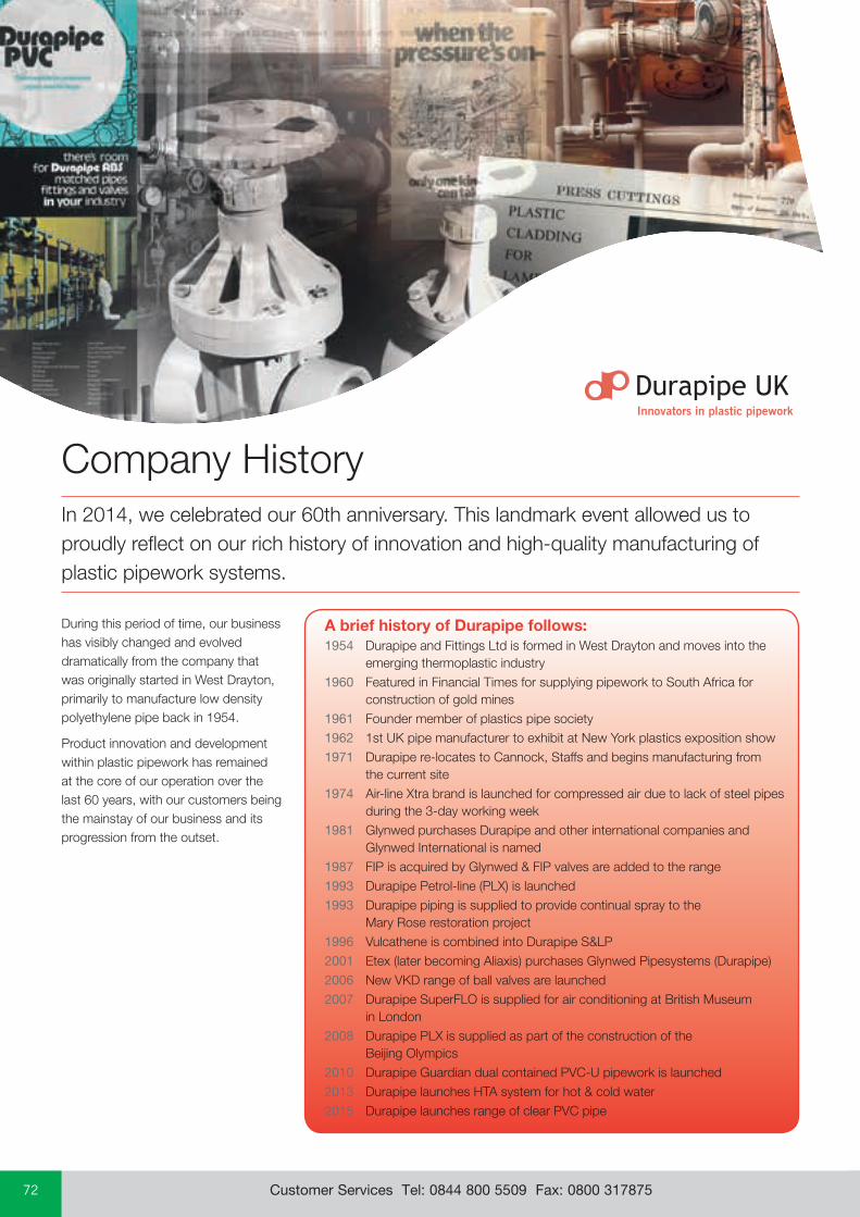
email: [email protected] web: www.durapipe.co.ukCustomer Services Tel: 0844 800 5509 Fax: 0800 31787572
Company HistoryIn 2014, we celebrated our 60th anniversary. This landmark event allowed us to proudly reflect on our rich history of innovation and high-quality manufacturing of plastic pipework systems.
During this period of time, our business has visibly changed and evolved dramatically from the company that was originally started in West Drayton, primarily to manufacture low density polyethylene pipe back in 1954.
Product innovation and development within plastic pipework has remained at the core of our operation over the last 60 years, with our customers being the mainstay of our business and its progression from the outset.
A brief history of Durapipe follows:1954 Durapipe and Fittings Ltd is formed in West Drayton and moves into the
emerging thermoplastic industry1960 Featured in Financial Times for supplying pipework to South Africa for
construction of gold mines 1961 Founder member of plastics pipe society 1962 1st UK pipe manufacturer to exhibit at New York plastics exposition show 1971 Durapipe re-locates to Cannock, Staffs and begins manufacturing from
the current site 1974 Air-line Xtra brand is launched for compressed air due to lack of steel pipes
during the 3-day working week 1981 Glynwed purchases Durapipe and other international companies and
Glynwed International is named 1987 FIP is acquired by Glynwed & FIP valves are added to the range 1993 Durapipe Petrol-line (PLX) is launched 1993 Durapipe piping is supplied to provide continual spray to the
Mary Rose restoration project 1996 Vulcathene is combined into Durapipe S&LP 2001 Etex (later becoming Aliaxis) purchases Glynwed Pipesystems (Durapipe) 2006 New VKD range of ball valves are launched 2007 Durapipe SuperFLO is supplied for air conditioning at British Museum
in London 2008 Durapipe PLX is supplied as part of the construction of the
Beijing Olympics 2010 Durapipe Guardian dual contained PVC-U pipework is launched2013 Durapipe launches HTA system for hot & cold water2015 Durapipe launches range of clear PVC pipe
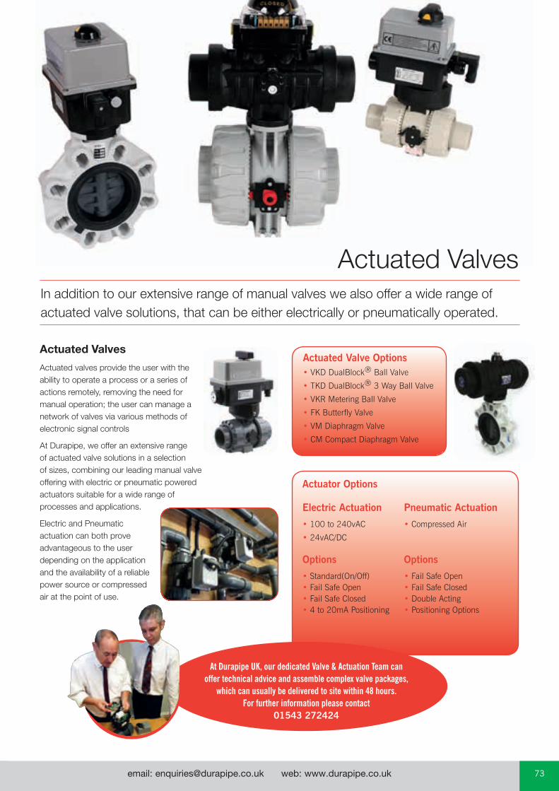
email: [email protected] web: www.durapipe.co.uk 73Customer Services Tel: 0844 800 5509 Fax: 0800 317875
In addition to our extensive range of manual valves we also offer a wide range of actuated valve solutions, that can be either electrically or pneumatically operated.
Actuated Valves
Actuated valves provide the user with the ability to operate a process or a series of actions remotely, removing the need for manual operation; the user can manage a network of valves via various methods of electronic signal controls
At Durapipe, we offer an extensive range of actuated valve solutions in a selection of sizes, combining our leading manual valve offering with electric or pneumatic powered actuators suitable for a wide range of processes and applications.
Electric and Pneumatic actuation can both prove advantageous to the user depending on the application and the availability of a reliable power source or compressed air at the point of use.
Actuated Valves
Actuated Valve Options• VKD DualBlock® Ball Valve
• TKD DualBlock® 3 Way Ball Valve
• VKR Metering Ball Valve
• FK Butterfly Valve
• VM Diaphragm Valve
• CM Compact Diaphragm Valve
Actuator Options
Electric Actuation Pneumatic Actuation
• 100 to 240vAC • Compressed Air
• 24vAC/DC Options Options
• Standard(On/Off) • Fail Safe Open• Fail Safe Open • Fail Safe Closed• Fail Safe Closed • Double Acting• 4 to 20mA Positioning • Positioning Options
At Durapipe UK, our dedicated Valve & Actuation Team can offer technical advice and assemble complex valve packages,
which can usually be delivered to site within 48 hours. For further information please contact
01543 272424
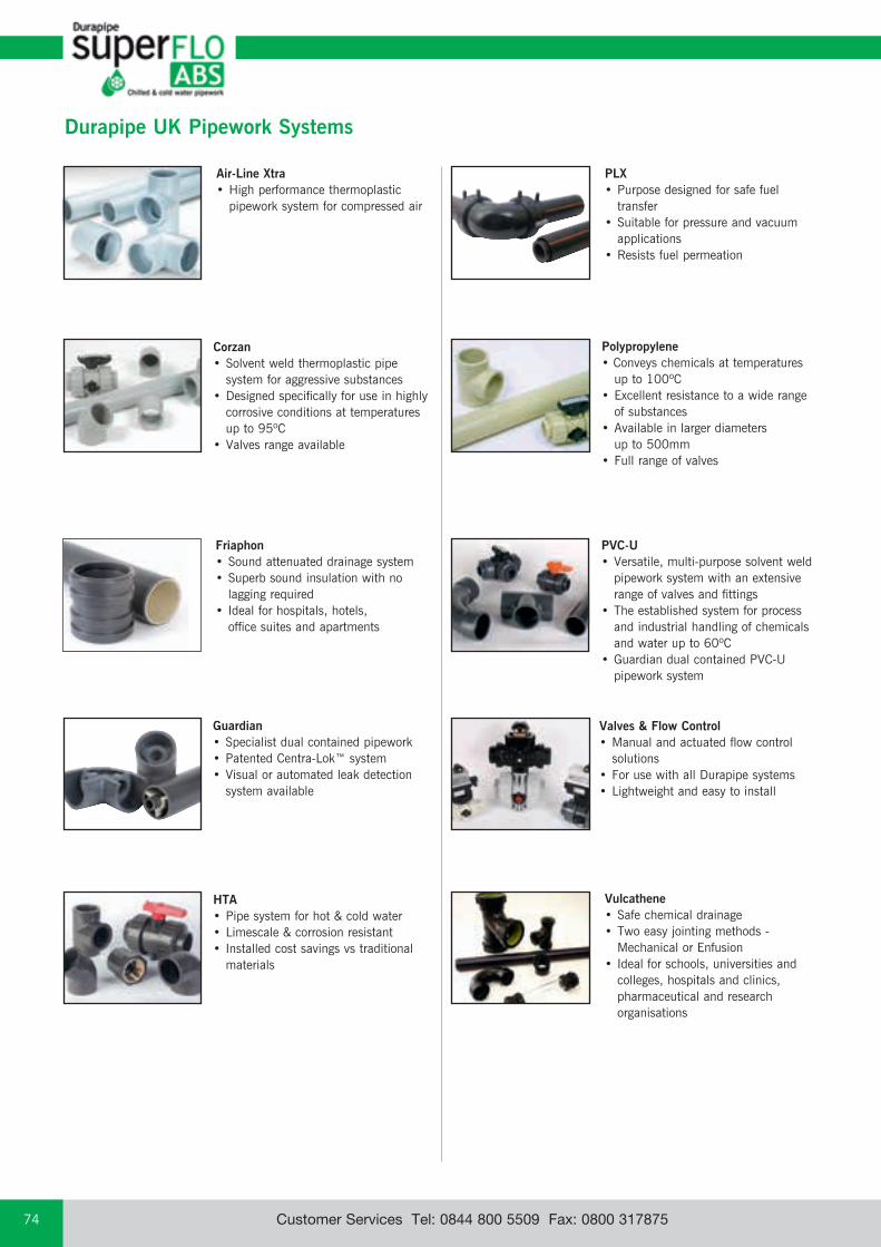
Customer Services Tel: 0844 800 5509 Fax: 0800 31787574
Vulcathene• Safe chemical drainage • Two easy jointing methods -
Mechanical or Enfusion • Ideal for schools, universities and
colleges, hospitals and clinics, pharmaceutical and research organisations
HTA• Pipe system for hot & cold water• Limescale & corrosion resistant• Installed cost savings vs traditional
materials
Durapipe UK Pipework Systems
Corzan• Solvent weld thermoplastic pipe
system for aggressive substances• Designed specifically for use in highly
corrosive conditions at temperatures up to 95ºC
• Valves range available
Air-Line Xtra • High performance thermoplastic
pipework system for compressed air
Valves & Flow Control • Manual and actuated flow control
solutions • For use with all Durapipe systems • Lightweight and easy to install
PLX• Purpose designed for safe fuel
transfer• Suitable for pressure and vacuum
applications • Resists fuel permeation
Polypropylene • Conveys chemicals at temperatures
up to 100ºC• Excellent resistance to a wide range
of substances• Available in larger diameters
up to 500mm• Full range of valves
PVC-U• Versatile, multi-purpose solvent weld
pipework system with an extensive range of valves and fittings
• The established system for process and industrial handling of chemicals and water up to 60ºC
• Guardian dual contained PVC-U pipework system
Guardian• Specialist dual contained pipework• Patented Centra-Lok™ system• Visual or automated leak detection
system available
Friaphon• Sound attenuated drainage system• Superb sound insulation with no
lagging required• Ideal for hospitals, hotels,
office suites and apartments
1. DEFINITIONS: ‘Seller’ shall mean Glynwed Pipe Systems Limited, registered in England under number
1698059. ‘Buyer’ shall mean any company, organisation or individual to whom a quotation is offered, or whose order is accepted by the Seller.
2. CONDITIONS: All offers, quotations, estimates, acceptances and contracts are subject to these
Conditions of Business and any terms or conditions which any other person shall seek to impose or make part of any contract shall, so far as is inconsistent with these Conditions of Business, not apply unless expressly agreed by the Seller in writing. The headings in these conditions are for convenience only and shall not affect their interpretation.
3. QUOTATIONS AND PRICE VARIATION: a) Any quotation given by the Seller is an invitation to the Buyer to make an offer only and
no order of the Buyer placed with the Seller in pursuance of a quotation or otherwise shall be binding on the Seller unless and until it is accepted in writing by the Seller.
b) Unless stated otherwise, all quotations and published price lists are ex works, exclusive of VAT and shall remain valid for 30 days or such a period as may be quoted but nevertheless the Seller may amend or withdraw any quotation by written or oral notice. Quotations may be varied if the Buyer makes variations in his specifications.
c) Certain products are denoted ‘MTO’ in the Seller’s published price lists. These products are Made to Order Goods and the Seller manufactures or procures these goods on a bespoke basis only. Where a Buyer has made an offer for ‘MTO’ products that the Seller has accepted in writing the Buyer forfeits their right to cancel their offer unless the Seller confirms in writing that it will accept cancellation by the Buyer. Where the Seller does not provide written confirmation of the Buyer’s cancellation the Buyer remains liable for the full contractual value of all ‘MTO’ products.
4. STATEMENTS OR REPRESENTATIONS TO THE BUYER: If any statement or representation has been made to the Buyer upon which the Buyer relies
other than in the documents enclosed with the Seller’s quotation, the Buyer must set out that statement or representation in a document to be attached to or endorsed on the order in which case the Seller may submit a new quotation.
5. DELIVERY - TIME: a) Any period for delivery given at any time and in any manner by the Seller is an estimate
only and is not binding on the Seller. Delivery periods are normally calculated from the later of:
i) acceptance of order; or
ii) where applicable, the receipt by the Seller of a detailed specification or drawings.
b) Time shall not be deemed to be of the essence of the contract. Failure by the Seller to meet any quoted delivery period for any part or the whole of the order shall not entitle the Buyer to rescind the contract or to claim damages of any nature.
c) The Seller will endeavour to comply with reasonable requests by the Buyer for postponement of delivery but shall be under no obligation to do so. Where delivery is postponed otherwise than due to default by the Seller the Buyer shall pay all costs and expenses including a reasonable charge for storage and transportation occasioned thereby and an extra charge for split delivery if applicable.
d) The Buyer will receive delivery of any consignment between the hours of 8.00am and 4.00pm Monday to Friday inclusive, unless otherwise agreed in writing. Cost incurred by the Seller arising from the Buyer’s refusal to accept consignments within the agreed hours shall be borne by the Buyer.
6. DELIVERY AND RISK: a) Except where stated to the contrary in the contract, delivery shall be made as follows:
i) where the Buyer provides the transport, delivery shall be made ex the Seller’s works;
ii) where the Seller provides the transport, delivery shall be made to the premises of the Buyer, or the premises of the Buyer’s customer or works site if the Buyer has requested delivery to be so made but where the Buyer has made such a request the Seller will make a first delivery to the Buyer’s customer or works site as so much of the goods as is available for that delivery but subsequent deliveries will be made to the premises of the Buyer.
b) The Seller may at its discretion make partial delivery of orders and invoice the same.
c) Risk in the goods shall pass on delivery.
d) Where goods are sent FOB the Seller’s responsibility shall cease when the goods are placed on board ship or aircraft without the need for the Seller to give notice to the Buyer and the provisions of Section 32(3) of the Sale of Goods Act 1979 shall not apply.
7. OWNERSHIP OF GOODS: a) The goods shall remain the sole and absolute property of the Seller as legal and equitable
owner until such time as the Buyer shall have paid to the Seller the contract price together with the full price of any other goods the subject of any contract between the Seller and the Buyer.
b) The Buyer acknowledges that until such time as the property in the goods passes to the Buyer he is in possession of the goods as a bailee and fiduciary agent for the Seller and the Purchaser shall store the goods in such a manner that they are clearly identifiable as the property of the Seller.
c) Until payment due under all contracts between the Buyer and the Seller had been made in full, in the event of sale of the goods by the Buyer:
i) the Seller shall be entitled to trace all proceeds of sale received by the Buyer through any bank or other account maintained by the Buyer; and
ii) the Buyer shall if requested by the Seller in writing to so assign its rights to recover the selling price of the goods from the third parties concerned. Such monies to be held separately by the Buyer as agent on behalf of the Seller.
d) The Seller may for the purpose of recovery of its goods enter upon any premises where they are stored or where they are reasonably thought to be stored and may repossess the same.
8. TERMS OF PAYMENT: In the event of default in payment according to the agreed payment terms between the
Seller and the Buyer – ie: by the end of the month following the month of despatch of the goods the Seller shall be entitled without prejudice to any other right or remedy to suspend all further deliveries and to charge interest on any amount outstanding at the rate of 2% per month until payment in full is made (a part of a month being treated as a full month for the purpose of calculating interest).
9. SHORTAGES AND DEFECTS APPARENT ON DELIVERY: a) It shall be the responsibility of the Buyer to inspect or arrange for an inspection of the
goods on delivery whether the goods are delivered to the Buyer’s premises or to the premises of the Buyer’s customer or to a works site. If no such inspection is made the Buyer shall be deemed to have accepted the goods.
b) The Buyer shall have no claim for shortages or defects apparent on inspection unless:
i) a written complaint is made to the Seller within three days of receipt of the goods specifying the shortage or defect; and
ii) the Seller is within seven days of receipt of the complaint given an opportunity to inspect the goods and investigate the complaint before any use is made of the goods.
c) If a complaint is not made to the Seller as herein provided then in respect of such shortages or defects the goods shall be deemed to be in all respects in accordance with the contract and the Buyer shall be bound to pay for the same accordingly.
10. CLAIMS FOR DEFECTS NOT APPARENT ON INSPECTION: a) The Buyer shall have no claim for defects not apparent on inspection unless the Seller
is notified of defective workmanship or materials within twelve months from delivery of the goods. Provided that the goods have been installed and applied in accordance with any relevant recommendations made by the Seller, the Seller will at its option replace the goods or refund the net invoiced price in respect of the goods which have been shown to be defective. If the Seller does so supply substitute goods the Buyer shall be bound to accept such substituted goods in full satisfaction of the obligations of the Seller under the contract.
b) The Buyer shall in any event have no claim or set-off in respect of defects unless a written complaint is sent to the Seller as soon as the defect is noticed and no use is made of the goods thereafter or alteration made thereto by the Buyer before the Seller is given an opportunity to inspect the goods.
c) The Buyer is responsible for ensuring that the goods are fit for any particular purpose, and no warranty or condition of fitness for any particular purpose is to be implied into the contract.
11. LIABILITY: Save as stated in Conditions 9 and 10 (and save in respect of death or personal injury
resulting from the negligence of the Seller its servants or agents) the Seller shall not be liable for any claim or claims for direct or indirect consequential or incidental injury loss or damage made by the Buyer against the Seller whether in contract or in tort (including negligence on the part of the Seller its servants or agents) arising out of or in connection with any defect in the goods or their fitness or otherwise for any particular purpose or any act omission neglect or default of the Seller its servants or agents in the performance of the contract.
12. FORCE MAJEURE: Notwithstanding anything herein contained neither the Buyer nor the Seller is to be held
liable for any delay or failure to carry out the contract due wholly or in part to an act of God action by any Government whether British or foreign civil war strikes and/or lockouts wheresoever occurring fire trade disputes floods or unfavourable weather or any material becoming unavailable or irreplaceable (whether at all or at commercially acceptable prices) or any other circumstances beyond the control of the Seller.
13. SUB-CONTRACTING: The Seller reserves the right to sub-contract the fulfilment of any order or any part thereof.
14. INSOLVENCY AND BREACH OF CONTRACT: In the event that:
a) the Buyer commits any breach of the contract and fails to remedy such breach (if capable of remedy) within a period of thirty days from receipt of a notice in writing from the Seller requesting such remedy; or
b) any distress or execution is levied upon any of the goods or property of the Buyer; or
c) the Buyer offers to make any arrangements with or for the benefit of its creditors or (if an individual) becomes subject to a petition for a bankruptcy order or (being a limited company) has a receiver appointed of the whole or any part of its undertaking property or assets; or
d) an order is made or a resolution is passed or analogous proceedings are taken for the winding up of the Buyer (save for the purpose of reconstruction or amalgamation with insolvency and previously approved in writing by the Seller) the Seller shall thereupon be entitled without prejudice to its other rights hereunder forthwith to suspend all further deliveries until the default has been made good or to determine the contract and any unfulfilled part thereof or at the Seller’s option to make partial deliveries. Notwithstanding any such termination the Buyer shall pay to the Seller at the contract rate for all the goods delivered up to and including the date of termination.
15. INDUSTRIAL PROPERTY RIGHTS: If goods supplied by the Seller to the Buyer’s design or specifications infringe or are alleged
to infringe any patent or registered design right or copyright the Buyer will indemnify the Seller against all damages, costs and expenses incurred by the Seller as a result of the infringement or allegation. The Buyer will give the Seller all possible help in meeting any infringement claim brought against the Seller.
16. BUYER’S ERROR IN ORDERING: In the event the Buyer orders incorrectly the Seller will be under no obligation to the Buyer
to rectify or assist in rectifying the error.
17. LAW AND JURISDICTION: The contract shall be subject in all respects to English Law and to the jurisdiction of the
English Courts.
DURAPIPE UK CONDITIONS OF SALE
email: [email protected] web: www.durapipe.co.uk 75

Distributor
04900020 October 2015
Registered office:
Durapipe UKWalsall Road Norton CanesCannockStaffordshireWS11 9NSUnited KingdomTel: +44 (0)1543 279909Fax: +44 (0)1543 279450email: [email protected]: www.durapipe.co.ukTwitter: @DurapipeUK
Durapipe UK reserves the right to modify the details in this publication as products and specifications are updated and improved. The content of this publication is for general information only and it is the user’s responsibility to determine the suitability of any product for the purpose intended.
For further information on all Durapipe UK products and services contact our Customer Services Department as detailed below.
Customer Services Tel: 0844 800 5509 Fax: 0800 317875
Durapipe UK is a trade name of Glynwed Pipe Systems Ltd. Company Number 1698059.
Durapipe SuperFLO
AB
S Technical Data &
Dim
ensionsO
CTO
BER
2015