building energy management applications
TRANSCRIPT

Building Energy Management Applications
Implementation of a Building Energy Management System, including Technical
Audit and Measurement and Verification planning
Dávid Pálinkás
Thesis to obtain the Master of Science Degree in
Energy Engineering and Management
Supervisors: Prof. Carlos Augusto Santos Silva
Prof. Valentí Fontserè Pujol
Examination Committee
Chairperson: Prof. Jorge de Saldanha Gonçalves Matos
Supervisor: Prof. Carlos Augusto Santos Silva
Member of the Committee: Prof. Paulo José da Costa Branco
November 2016

I
ACKNOWLEDGEMENTS
I acknowledge Antoni Quintana Poblet and Angel Paiz Farre for their time and help they provided me
throughout my internship.
I acknowledge KIC InnoEnergy for the opportunity to be part of the Renewable Energy Master program.
I wish to thank my family the support they provided me in the two years of my Masters in the beautiful cities of
Stockholm, Lisbon and Barcelona. Without their support and caring nothing would have been possible.
II
ABSTRACT
Global warming and energy supply security are two of the most urgent issues that are being addressed in the
European Union. The building sector has a substantial share in both energy usage and CO2 emissions. The
residential and tertiary sector accounts for approximately 40% of the total final energy consumption in the EU.
In this thesis, the partial results of the evaluation of a cloud-based Building Energy Management System under
development are shown. First, a technical audit was done in the building. After some insight to the
implementation, the energy savings were determined with the measurement and verification process of
International Performance Measurement and Verification Protocol. Then, the energy consumption forecasting
feature of the system was evaluated. Finally, a business plan was created for the future distribution of this
product.
The objective of the thesis was to introduce and evaluate the Building Energy Management System and finally,
to develop a business model for the commercialization of the system. First, it was found, that the system
reached modest energy savings in the summer in a pilot project in Barcelona. Second, the energy forecasting
feature of the system has significant errors on an hourly basis; which is acceptable from a product under
development. Third, a business plan is drawn up for the growing market of Building Energy Management
Systems.
Key-words: energy, management, efficiency, measurement and verification, Building Energy Management
System, BEMS

III
RESUMO
Esta tese descreve e analisa os resultados experimentais da implementação de um sistema de gestão de
edifícios inovador. Para isso, foi desenvolvido em primeiro lugar uma auditoria técnica aos edifícios em estudo
na cidade de Barcelona, de forma a caraterizar os principais equipamentos instalados e responsáveis pelo
consumo de energia. Em seguida, foi implementada uma metodologia de monitorização e verificação baseada
no protocolo IPMVP que permitiu avaliar o sistema de previsão do sistema de gestão de energia. Concluiu-se
que a introdução deste sistema permitiu poupanças na ordem dos 5% durante a fase piloto no período de
verão em Barcelona. Contudo, o sistema de previsão apresentou ainda erros significativos, pelo que se conclui
que é necessário desenvolver mais os algoritmos de previsão em análise.
Foi ainda desenvolvido um plano de negócios para a implementação do sistema, do qual se conclui que existe
uma oportunidade interessante para a comercialização deste sistema, desde que o sistema de previsão
melhore o seu desempenho.
Palavras Chave: Gestão de Energia, Eficiência Energética, medição e verificação, previsão de consumos de
energia, Sistemas de Gestão de Energia em Edifícios

IV
Glossary
This section describes all notations and acronyms used in this thesis report
AHU Air Handling Unit
BMS Building Management System
BEMS Building Energy Management System
BMC Business Model Canvas
BT Base Temperature
CDD Cooling Degree Days
DR Demand Response
DD Degree Days
ECM Energy Conservation Measure
ESCO Energy Service Company
HDD Heating Degree Days
HVAC Heating, Ventilation and Air Conditioning
IPMVP International Performance Measurement and Verification Protocol
SaaS Software-as-a-Service
SCADA Supervisory Control and Data Acquisition
V
Table of Contents
Table of Contents .................................................................................................................................................... V
List of tables .......................................................................................................................................................... VII
List of figures ........................................................................................................................................................ VIII
1 Introduction.................................................................................................................................................... 1
1.1 Motivation ................................................................................................................................................. 1
1.2 Objectives .................................................................................................................................................. 2
1.3 Contributions ............................................................................................................................................. 3
1.4 Structure of the thesis ............................................................................................................................... 3
2 Concepts and State of the Art ........................................................................................................................ 5
2.1 Smart Grids ................................................................................................................................................ 5
2.2 Flexibility of the Power Grid ....................................................................................................................... 5
2.2.1 Demand Side Management ................................................................................................................. 5
2.2.2 Benefits of Demand Side Management .............................................................................................. 7
2.3 ISO 50001 ................................................................................................................................................... 8
2.4 Measurement and Verification .................................................................................................................. 9
2.5 BEEST Project ........................................................................................................................................... 13
2.5.1 Dexcell Energy Manager .................................................................................................................... 14
2.5.2 START-UP Apps .................................................................................................................................. 15
3 Methodology ................................................................................................................................................ 23
3.1 Technical audit ......................................................................................................................................... 23
3.1.1 Building data...................................................................................................................................... 23
3.1.2 Building Management System........................................................................................................... 23
3.1.3 HVAC configuration ........................................................................................................................... 24
3.1.4 LAN .................................................................................................................................................... 24
3.1.5 Users’ behaviour ............................................................................................................................... 24
3.2 Implementation ....................................................................................................................................... 24
3.3 Collecting energy data ............................................................................................................................. 25
3.4 Regression analysis .................................................................................................................................. 25

VI
3.5 Measurement and Verification ................................................................................................................ 26
4 Case studies .................................................................................................................................................. 29
4.1 ICAEN Building.......................................................................................................................................... 29
4.2 Av. Roma 25 ............................................................................................................................................. 34
4.3 NH Waalwijk ............................................................................................................................................. 35
4.4 De Lijn Gentbrugge .................................................................................................................................. 36
5 Results .......................................................................................................................................................... 38
5.1 Measurement and Verification in ICAEN building ................................................................................... 38
5.2 Results of START-UP PRODUCT 1 ............................................................................................................. 48
6 Business plan for Partners ............................................................................................................................ 54
6.1 Partnership with START-UP ...................................................................................................................... 54
6.1.1 Requirements for Partners ................................................................................................................ 54
6.1.2 Benefits of being a Partner ................................................................................................................ 54
6.1.3 Potential Partners.............................................................................................................................. 55
6.2 Market analysis ........................................................................................................................................ 56
6.2.1 Market and Growth ........................................................................................................................... 56
6.2.2 Target Market .................................................................................................................................... 56
6.2.3 Competitor Analysis .......................................................................................................................... 57
6.2.4 Differentiation and Positioning ......................................................................................................... 59
6.2.5 Risks ................................................................................................................................................... 59
6.3 Management Plan .................................................................................................................................... 60
6.4 Business Model Canvas ............................................................................................................................ 62
6.5 Financial Plan ........................................................................................................................................... 65
7 Conclusions................................................................................................................................................... 70
8 References .................................................................................................................................................... 72
VII
List of tables
Table 1 Chillers and Boilers in ICAEN building....................................................................................................... 31
Table 2 Air Handling Units in ICAEN ...................................................................................................................... 34
Table 3 Meters in ICAEN building .......................................................................................................................... 39
Table 4 Number of removed holidays ................................................................................................................... 42
Table 5 Calculation of normalised energy savings ................................................................................................ 46
Table 6 Chiller energy consumption ..................................................................................................................... 46
Table 7 Boiler energy consumption ...................................................................................................................... 46
Table 8 Price and CO2 emission of electricity and natural gas .............................................................................. 47
Table 9 Energy and CO2 emission savings ............................................................................................................. 47
Table 10 Summary of PRODUCT 1 errors ............................................................................................................. 52
Table 11 Packages of applications......................................................................................................................... 60
Table 12 Type of energy savings with START-UP apps .......................................................................................... 62
Table 13 Revenues from commissioning the Platinum package ........................................................................... 66
Table 14 Direct costs of a project.......................................................................................................................... 66
Table 15 Overhead cost of a Partner .................................................................................................................... 66
Table 16 Calculation of cash flow .......................................................................................................................... 67

VIII
List of figures
Figure 1 Share of buildings in final energy consumption in the EU, 2012 [6] ......................................................... 2
Figure 2 Energy consumption by subsector in services (2012) [6] .......................................................................... 2
Figure 3 Energy Management System Model of ISO 50001 [18] ............................................................................ 9
Figure 4 Companies’ responsibilities in the BEEST project ................................................................................... 14
Figure 5 Logo of START-UP .................................................................................................................................... 14
Figure 6 User interface of Dexcell Energy Manager .............................................................................................. 15
Figure 7 Information flow of START-UP PRODUCT 1 app ...................................................................................... 16
Figure 8 Inputs and Outputs of START-UP PRODUCT 1 ......................................................................................... 17
Figure 9 Screenshot of START-UP PRODUCT 1 results .......................................................................................... 17
Figure 10 Structure of START-UP PRODUCT 4 ....................................................................................................... 20
Figure 11 On/off schedule and set-points by START-UP PRODUCT 3 ................................................................... 21
Figure 12 Photo of ICAEN building [25] ................................................................................................................. 29
Figure 13 Shades on the façade on the left and entrance with the atrium on the right in ICAEN........................ 30
Figure 14 Position of ICAEN building [25] ............................................................................................................. 30
Figure 15 Scheme of boilers in ICAEN ................................................................................................................... 31
Figure 16 Photo of one of the boilers on the top floor of the ICAEN office .......................................................... 32
Figure 17 Scheme of chillers in ICAEN ................................................................................................................... 33
Figure 18 Photo of one of the chillers in ICAEN .................................................................................................... 33
Figure 19 Blueprint of the third floor in ICAEN building [25] ................................................................................ 34
Figure 20 Comsa office at Av. Roma 25, Barcelona [26] ....................................................................................... 35
Figure 21 NH Waalwijk [26] .................................................................................................................................. 35
Figure 22 De Lijn Gentbrugge [26] ........................................................................................................................ 36
Figure 23 Energy consumption of heating and cooling in the baseline period ..................................................... 40
Figure 23 The location of the weather station and the ICAEN office [26] ............................................................ 41
Figure 24 R2 values for different Base Temperatures ........................................................................................... 42
Figure 25 Linear regression analysis for CDD and electricity consumption .......................................................... 43
Figure 26 Regression analysis for HDD and gas consumption on daily basis ........................................................ 44
Figure 27 Regression analysis for HDD and gas consumption on monthly basis .................................................. 44
Figure 28 Forecasted total energy use in Av. Roma .............................................................................................. 48
Figure 29 Forecasted total energy use in ICAEN ................................................................................................... 49
Figure 30 Forecasted HVAC energy use in ICAEN ................................................................................................. 50
Figure 31 Forecasted total energy use in De Lijn Gentbrugge .............................................................................. 51
Figure 32 Forecasted total energy use in NH Waalwijk ........................................................................................ 52
Figure 33 The BEMS market in Europe in 2014 [33] ............................................................................................. 56
Figure 34 Business Model Canvas of START-UP insert as appendix [37].............................................................. 62
Figure 35 Cash flow of a Partner’s sales of START-UP products ........................................................................... 68

IX

1
1 Introduction
1.1 Motivation
Global warming and energy supply security are two of the most urgent issues that are being addressed in the
European Union. The CO2 emissions in the EU-28 countries were around 4000 Million ton CO2 in 2012 [1].
However, the CO2 emission data show a decreasing tendency, the most significant drop was around 2008, due
to the global financial crisis [1]. In addition to the severe effects of global warming, the European Union is
facing serious energy dependency on fossil fuels that endanger the energy security in most of the member
countries [2], [3]. In the Statistical Pocketbook 2015 written by the European Commission, it is illustrated
clearly that more than 50% of the fuel consumption is based on imports from non-EU regions, which makes the
EU economy vulnerable to changes in world market or politics [1].
Understanding the possible future consequences of these issues, the Member States of the EU set the 2020
targets; Reaching 20% lower CO2 emissions compared to the 1990 level, increasing energy efficiency by 20%
and increasing the share of renewable energy sources (RES) in the energy mix by 20% [4]. Also, the European
Council set the target of reducing green house gas emissions 80-95% below the 1990 levels by 2050. These
plans help to moderate the climate change and, also, the need for imported fuels. In order to provide practical
and objective analysis to reach a low-carbon economy, the European Climate Foundation (ECF) developed the
European Roadmap 2050 [5].
The building sector has a substantial share in both energy usage and CO2 emissions. As seen in Figure 1, the
residential and tertiary sector accounts for approximately 40% of the total final energy consumption in the EU,
while in Estonia, Latvia and Hungary these two sector represent even more than 45% of the total final energy
consumption [6], [7]. Moreover, these sectors are responsible for around 55% of the electricity consumption
and 36% of the CO2 emissions in the EU. Considering that the 35% of the building park is over 50 years old,
there is a huge potential in energy savings and in lowering CO2 emissions of buildings [8].

2
Figure 1 Share of buildings in final energy consumption in the EU, 2012 [6]
Around one third of the energy consumption of the building sector is for the European non-residential
buildings. Considering the non-residential buildings, also called tertiary buildings, the share of different sub-
sectors is illustrated in Figure 2. As seen in the figure, the subsectors of offices, hotels and restaurants consume
around 30% of the energy of services [6].
Figure 2 Energy consumption by subsector in services (2012) [6]
All in all, the tertiary sector consumes a significant portion of the final energy consumption and emits a
considerable amount of CO2. This gives the sector a critical role in reaching the EU's economic goals, in fighting
against the global warming and therefore; foresees the development of new innovative products in the
building and energy industry.
1.2 Objectives
The scope of the thesis is to give an introduction to demand side management methods generally, to introduce
the commissioning of and evaluate a new Building Energy Management product. Firstly, energy savings are
3
measured and verified that the Building Energy Management System in question can reach in the pilot projects.
This verification is to be done following the IPMVP protocol. Secondly, the energy forecasts provided by the
Building Energy Management System are evaluated. Finally, a business plan is created for selling the product.
1.3 Contributions
The thesis is evaluating a newly developed Building Energy Management System and a business model for its
commercialization. There are lessons learnt from the implementation and use of the software and these are
examined.
1.4 Structure of the thesis
The thesis is structured in 7 main chapters. Firstly, the issue of high energy consumption in the building sector
is detailed in the introduction. Secondly, directly after the introduction, the thesis explains the different
concepts and the state of art of the literature of demand side management, the ISO50001 energy management
standard and the IPMVP protocol. Then, the BEEST project and the Building Energy Management System and its
applications are explained. Later, the implementation process of the software is described and the pilot
projects are introduced. In Chapter 5 the energy savings and the forecasted energy consumption are evaluated.
Chapter 6 is introducing a business model for the commercialization of the system, while the last chapter is
making conclusions about the thesis.

4
5
2 Concepts and State of the Art
2.1 Smart Grids
Thanks to the 20-20-20 plan and other incentives targeting reduced GHG emissions and fossil fuel imports, the
importance of energy efficiency and low-emission power generation is increasing. As RES based power
generation and electric vehicles (EVs) gain more and more ground, the burden of decentralized and
intermittent energy feed-in heralds the development of smart grid concepts [9], [10].
According to D. Kolokotsa et al. (2016), “Smart grids are electrical power grids that are more efficient and more
resilient and therefore, smarter than the existing conventional power grids” [11]. Being smart essentially
means the ability of eliminating blackouts, increased renewable energy penetration, higher energy efficiency
and lower energy costs. These features are realized through the incorporation of innovative information
technology and the two-way communication between the energy providers and consumers. In smart power
grids computers, automation systems, smart buildings, electric vehicles and other innovative smart
technologies are cooperating with the grid to optimize energy generation and consumption. Such a system can
be considered as the electric grid that can satisfy the needs of the 21th century; high efficiency, high reliability,
modern communications infrastructure, modern sensors and meters and demand side management
techniques. Thus, smart grids provide an ideal environment for smart applications in the building industry [11].
2.2 Flexibility of the Power Grid
The increased flexibility of the grid is one of the key characteristic that is important to reduce the fuel use and
emissions. A flexible power grid is capable of handling decentralised renewable energy sources, provide higher
reliability and able to handle demand peaks.
There are two main categories of sources of flexibility in an electrical power grid. These are supply side
flexibility and demand side flexibility.
Supply side flexibility that is achieved by dynamically fast responding conventional power plants,
combined power generation, co-generation, energy storage and the control of renewable energy feed-
in.
Demand-side flexibility that is possible with Demand Side Management (DSM) services, like improved
energy efficiency or load shifting [9], [12].
2.2.1 Demand Side Management
One of the most researched fields of flexibility is demand side management (DSM). DSM is aimed to improve
the energy system at the customer side. It can range from improving energy efficiency with better insulation
and better building materials to autonomous energy systems.

6
The development and implementation of DSM actions are driven by the fact that besides the increasing
efficiency of new devices, the energy consumption is steadily growing. However DSM promotes decentralized
energy generation, influencing loads is less expensive than building new power plants. [13]
The concept of DSM includes different approaches for manual energy conservation, energy efficiency programs
and load management programs based on smart pricing [10]. DSM can be categorized according to the timing
and the effect of the applied measures [13]:
Energy Efficiency
Time of Use (TOU)
Demand Response (DR)
Spinning Reserve (SR)
Energy Efficiency
All permanent changes on equipment or improvements on physical properties of the systems can be
categorized as an energy efficiency measure (EE). These measures result in immediate and continuous energy
and emission reductions, while other DSM methods are just shifting loads. Consequently it is the most
widespread and primary method applied at in DSM. After improving efficiency, dynamic DSM methods can be
implemented.
Time of Use
In case of TOU tariffs, energy prices are different in each period of the day to force consumers to reschedule
their processes and energy consumption in order to minimize costs. The highest costs are in the periods of
peak load, while significantly lower prices are offered in non-peak times. [10] The TOU price schedule is not
changed frequently as it is included in the contracts between the consumers and the utilities.
Demand Response
In DR a signal (trigger) is sent by the Distribution or Transmission System Operator (DSO/TSO) containing price
and/or command for load shifting. The reaction to the signal is not necessarily instantaneous; it may
correspond to a time period on the next day.
DR does not necessarily reduce energy usage; it is only the changed behaviour of the consumer in response to a
DR signal. If the performance of an air conditioning system is lowered for half an hour, then afterwards it takes
more time to reach the same comfort level in the building on the former performance. It may end up in higher
energy consumption or generate a new peak as a rebound effect.
Han et al. (2008) categorized DR programs as incentive based and time rate based [14]:
Direct load control: the grid operator has access to the customers’ equipment.
Interruptible rates: a special contract with limited sheds.

7
Emergency demand response program: DR is triggered with an emergency signal.
Capacity market programs: DR is done when the grid requests.
Demand bidding programs: bidding for DR actions.
Time based rates in DR:
TOU rates: a simple price schedule.
Critical peak pricing: price schedules with some flexibility.
Real time pricing (RTP): customers are aware of and pay according to real time wholesale market
prices.
According to Palensky et al. (2011), some of these DR measures are market based and some of them are
physical in the sense that they are induced to conserve energy supply quality. The methods that are market
based are the ones that include real time pricing, price signals and other similar contrPRODUCT 3. While, the
physical DR programs are sending binding requests to trigger demand management if necessary. This may
happen if the power line quality is decreased due to high demand, maintenance or failure of any device [13].
Spinning Reserve
SR is the fastest way to implement demand side management. Typically power plants are in charge of SR in the
supply side management, but loads can act as negative SR in case the power consumption is correlated to the
state of the grid in a smart way. If the frequency of the grid decreases, a consumer reduces its power need.
Developed technology and communication system is needed to act as a negative SR.
2.2.2 Benefits of Demand Side Management
Due to the short occupancy periods, office buildings exceptionally fit for DSM purposes [15]. Arteconi et al.
(2016) confirmed the demand-side flexibility potential for average sized office buildings [9].
A large variety of advantages can be gained with demand side management. Lower peak load prices, price
volatility and reduced risks of black outs due to the reduced burden on the power system are the main
economic advantages. According to Faruqui et al. (2012), between 5 to 10 billion dollars could be saved in the
US by reducing the peak load by 5%. Also, the reduced consumers’ energy bills and lower transmission and
distribution investments is to be considered as a great economical advantage of DSM. [16]
In addition to the financial benefits, demand side flexibility contributes significantly to sustainability. Besides
the reduction in direct GHG emissions, as at peak hours the increased energy needs are usually satisfied with
less effective fossil fuel based power plants, less significant peak power allows the cheaper and easier
integration of intermittent renewable energy based power plants.
Supplementary to local economic and environmental advantages, demand side flexibility allows improved
energy exchange and generation allocation between countries that results in lower risk of blackouts, lower
intermittency of the power system and generally less use of inefficient power generation methods [17].

8
2.3 ISO 50001
There are several ways to improve energy efficiency of buildings but tracking savings is an essential part of
these projects. Monitoring energy savings has to be standardized to make it more effective and traceable. The
ISO 50001 standard introduces a standardized way of energy management, while the IPMVP protocol creates
the fundaments of the Measurement and Verification process.
ISO (International Organization for Standardization) is a group of national standards bodies. These ISO member
bodies prepare standards getting together in technical boards for each project. Also, governmental and non-
governmental organizations are involved in the creation of International Standards.
The ISO 50001 standard provides industrial and commercial facilities and organizations with a globally accepted
framework for the implementation of energy management systems. It includes energy procurement and use
while establishing a framework to implement strategies that can significantly reduce energy costs and CO2
emissions. Also, the framework helps sustaining savings in the future.
Since its release in June 2011, thousands of companies of various sizes are using the ISO 50001 standard
voluntarily to reduce costs and CO2 emissions. Its main purpose is to make the implementation of energy
management systems easier for companies [18].
The ISO 50001 is based on the Plan, Do, Check, Act (PDCA) framework that provides continuous improvement
for organizations while implementing energy management into their everyday life.
Plan: conduct energy audit, establish baseline, define Key Performance Indicators (KPIs), targets,
objectives and action plan needed
Do: implement the action plan
Check: monitoring and measurement process, report results
Act: take actions for continuous improvement
ISO 50001 provides several advantages and many ways to profit for organizations. Some of these are the
following:
Reduced costs of energy and production
Reduced energy and CO2 consumption
Compliance with energy efficiency laws
Increased competitiveness due to the lower costs
Better company image
The standard requires the companies to hire personnel, create documentation and implement technology. The
personnel can be an Environmental Manager or a Technical Auditor, who is responsible to do the
documentation of the action plan, to supervise energy monitoring and saving verification and to conduct

9
internal audits. In order to fulfil the duties of the personnel in charge, an energy management software is
essential [19].
In Figure 3 the energy management model of ISO 50001 is visible. Along with the standard, when the energy
audit and performance assessments are conducted and inefficiencies are identified, the possible retrofit
options shall be identified. By using proper economic analysis tools, risk assessment methods and appropriate
energy models, the preferred retrofit alternatives can be chosen and recorded in the energy policy by the
management. Then, the ECM is implemented and commissioned taking into account that the process may
interrupt the operation of the building or occupants. The final phase after the implementation of the ECM, that
is also the first phase in the future, is the measurement and verification of savings and the continuous
surveillance of the energy consumption data in the future. [20]
Figure 3 Energy Management System Model of ISO 50001 [18]
2.4 Measurement and Verification
The final phase of implementing demand side measures or energy efficiency measures is to validate and verify
energy savings. Once the ECMs are implemented and set up, standard Measurement and Verification (M&V)
methods, like the Best Practice Guide to Measurement and Verification of Energy Savings by AEPCA or the
IPMVP protocol can be used to verify energy and economic savings. [20]
The International Performance Measurement and Verification Protocol (IPMVP) is published by the Efficiency
Valuation Organization (EVO) to facilitate investment in demand management, renewable energy, energy
efficiency and water efficiency projects.

10
IPMVP Volume I is a document that gives guidance for common practice in measuring, calculating and
reporting results of energy or water efficiency projects in facilities. IPMVP introduces four different M&V
Options matching the needs of different projects all around the globe. Thus, it guarantees transparency,
reliability and consistency in savings reporting. Activities related to IPMVP can be in the form of site surveys,
metering, monitoring, calculating and reporting energy or water use. [21]
In the following the most important steps, definitions, factors and requirements of Measurement and
Verification planning, which were followed throughout the M&V process in the thesis, are explained.
M&V Option and boundary
IPMVP defines four different approaches, Option A, B, C and D for planning and conducting the M&V process. It
is not always straightforward which IPMVP Option to use in each case. It is necessary to examine each project
in detail and justify the chosen Option.
Option A is applied in case some of the parameters need to be estimated, meanwhile Options B is used if the
key parameters of energy saving are measured directly on the field. For example a lighting retrofit project is
Option A, because power draw is measured, while operating hours are only estimated. The measurement
period ranges from short-term to continuous; routine or non-routine adjustments may be necessary in both
cases.
Option C is the whole facility approach. This option is used when savings are determined on the facility or sub-
facility level and continuous measurements are done throughout the post-retrofit period. Option C can only be
effective, if the possible savings are significantly higher than the random energy variations.
Option D is used for calibrated simulations that are made in case there are no meters installed in the baseline
period. The reporting period simulation is calibrated with gas or electricity meters’ data and then used to
simulate the baseline consumption. This option may need specific knowledge and experience in energy
simulation [21].
The measurement boundary is a notional border, which is drawn around a system to determine the savings by
any ECM. For example it can restrict the measurements to a certain level of the HVAC, to measure only the
energy consumption of the chillers or boilers.
Interactive effects
Interactive effects are the energy effects that occur beyond the measurement boundary. It is important to
estimate their magnitude to determine savings properly. An example of interactive effects is the heating effect
of the light bulbs in a building.
Independent variables

11
The parameters that have measurable impact on the energy use and that are expected to change regularly are
called independent variables. There are several factors like occupancy, solar irradiance, temperature, etc. that
can be taken into account while choosing the most appropriate variable for the regression model. All the
possible variables need to be considered and justified for being used or not, as an independent variable.
Key parameters
The key parameters are usually the energy consumption data of the building. Comparing these key parameters
to the independent variable gives the correlation for the energy model. With the help of regression analysis, it
is possible to draw this correlation and use it for the normalization of the consumption. In order to get proper
correlations, it is advised to use as many the same source of data for calculations and evaluation in the baseline
and in the reporting period. In addition, all the data sources, meters and sensors need to be calibrated to
provide reliable and continuous data.
Base Temperature
It is crucial to consider the Base Temperature (BT) for the Degree Days (DD) calculations. Along with the
ASHRAE 89 standard, the BT is around 65 F and 18.3°C in the UK. BT is the temperature above cooling is needed
or below heating is needed in the building. In climates with heating and cooling season it is practical to define
different BTs for different seasons.
Routine and Non-Routine adjustments
Any change in the facility size, the design or operation of systems, the schedule of occupants or any other non-
routine variance can affect the energy consumption that reduces the reliability of the M&V plan. These effects
are monitored and indicated and compensated by non-routine adjustments.
Routine adjustments are calculated with the help of identifiable energy-governing factors. Ambient
temperature may be considered as an energy-governing factor that changes routinely.
Basis of adjustment
The pre and post retrofit measurements are adjusted in order to compare the two periods in fixed conditions
and to see the effect of the ECM. To compare the measurements, two methods “Avoided Energy Use” and
“Normalized Savings” can be applied.
Normalized Savings
Normalized Savings means the cut in energy usage or energy cost that arose after the ECM was implemented
compared to the energy usage or cost that would have arisen in case the building had been used in the same
way as it was before, under normalized conditions. The normalized conditions can be an average of a longer
period or the conditions under the baseline period. The conditions of the reporting period cannot be used. In
case the conditions of the reporting period are used, the term of Avoided Energy Use or Savings is used.

12
Normalized savings are calculated in the following way:
Normalized Savings = (Baseline Energy + Routine Adjustments to fixed conditions + Non-routine Adjustments to
fixed conditions) – (Reporting Period Energy + Routine Adjustments to fixed conditions + Non-Routine
Adjustments to fixed conditions)
The engineer responsible for the calculations after the reporting period can also use the Avoided energy use
approach.
Avoided Energy Use
Avoided Energy Use means the cut in energy use that arose after the ECM was implemented comapred to the
energy usage that would have arisen in case the building had been used in the same way as it was before,
under the operating conditions of the reporting period. It is also called as Cost Avoidance or Savings.
Avoided Energy Use is calculated in the following way:
Avoided Energy Use = Adjusted-Baseline Energy – Reporting Period Energy + Non-Routine Adjustments of
Baseline Energy to Reporting-period conditions
Adjusted-Baseline Energy: Baseline energy + Routine adjustment to reporting period conditions.
Adjusted-Baseline Energy is calculated by developing mathematical model that correlates with the original
baseline energy data first, then inserting independent variables of the reporting period into the model to
produce the adjusted-baseline energy use.
Baseline and Reporting Period
It is crucial to make a proper decision about the length of the periods. The baseline period needs to cover at
least a whole operating cycle of consumption that may range from a few days to years. The reporting period
(also called post-retrofit period) has to cover at least the same operational cycle as the baseline period. In the
post-retrofit state, it is advised to make the same measurements as in the baseline with the same calibrated
meters and sensors.
Quality assurance
According to the IPMVP protocol, to keep the quality of the M&V plan high, the recorded data need revision by
multiple parties. Also, any decision related to adjustments are discussed and reviewed by the facility manager
and the M&V agent.
In the following some of the numerous risk factors in M&V plans that may endanger the quality and reliability
of a report are listed.

13
Estimated readings: In case the energy data is obtained in the form of bills, the frequency of readings
needs to be reviewed. Any significant vary due to rare readings needs to be modified to decrease the
distortion of the results.
Uncalibrated meters: Errors in measurement can have great effects on data and on the estimated
energy savings.
Unexpected changes in the building or in its use: Any changes in the building envelope, operation or
use need to be noted as those may have a significant impact on the energy consumption.
Incorrect data entry: Any mistake in the input data set may cause the distortion of the results;
therefore it is important to review the data used in multiple ways.
2.5 BEEST Project
The main objective of the Building Energy Efficiency Management & Smart Grid Integration Tools (BEEST)
project is to reduce energy costs in tertiary sector by developing a set of software (suite of applications) that
works as a Software-as-a-Service (SaaS) on top of the existing Building Management Systems (BMSs) and
optimizes the operation and energy management of buildings. The development of these apps is based on the
following needs in offices and hotels:
Optimization of facility management practices.
Optimization of energy purchasing practices.
Accessing the benefits of energy market deregulation.
The BEEST project is a KIC InnoEnergy Innovation Project. The aim of KIC Innovation Projects is to finance and
support market-oriented projects in the states of research and development, business development and
commercialization. The project is conducted by five individual companies and institutions with expertise on
different fields: Comsa Corporación, Dexma and Tecnalia in Spain and Enervalis and EnergyVille in Belgium.
Figure 4 visualizes the responsibilities of different companies involved in the development of the products.
Comsa Corporación is responsible for the Spanish pilot projects and the marketing strategies of the products.

14
Figure 4 Companies’ responsibilities in the BEEST project
START-UP
As an outcome of the BEEST project, the company called START-UP was created. The logo of START-UP is visible
on Figure 5. The companies Comsa Corporación, Enervalis and KIC InnoEnergy created the joint-venture to sell
the applications of this innovative Research and Development project.
Figure 5 Logo of START-UP
The company is defined as a SaaS provider and offers the suite of apps to reduce commercial building energy
consumption and energy unit price. As a SaaS provider, START-UP has partnership with Dexma who is
competitor on the field of energy management. Dexma provides the Dexcell Energy Manager as a platform as
of the applications. In addition, START-UP is doing marketing activities hand in hand with Dexma to create a
stronger brand.
2.5.1 Dexcell Energy Manager
Figure 6 shows Dexcell Energy Manager that can monitor and create reports on energy and water use. Besides
monitoring and reporting, the software can have alarms for different events and has a dashboard for apps that
makes energy surveillance faster and more convenient. There is a market place in the software for free or paid
custom apps.

15
Figure 6 User interface of Dexcell Energy Manager
The START-UP applications are designed to be apps of the marketplace and visible for the users of the Dexcell.
If the potential customers of START-UP show interest, they are directed to the local distributors and partners of
START-UP.
2.5.2 START-UP Apps
The suit of applications is providing new functionalities to the Dexcell Energy Manager. The Dexcell Energy
Manager and the newly developed apps work as a top layer and control the existing BMS in the building. The
apps are only used to control the HVAC system; therefore it is categorized as a Building Energy Management
System (BEMS). However no or only minimal physical intervention is needed in the BMS system, the installation
of additional energy meters may be necessary for the complete implementation of the solutions.
There are six individual applications under development or beta testing in the moment of the thesis. Their
function is to make operations easier and more efficient for offices and hotels.
The following list contains the apps and their state of development in the moment of the thesis:
PRODUCT 1 (installed, debugging and testing)
PRODUCT 3 (installed, debugging and testing)
PRODUCT 4 (under development)
PRODUCT 2 (under development)
PRODUCT 5 (before development)
PRODUCT 6 (before development)

16
START-UP PRODUCT 1
The main functionality of the app is the energy demand forecast of the following 48 hours. The forecast is
related to the HVAC energy consumption and is shown on a diagram on hourly basis.
The added value by the PRODUCT 1 app is the energy use awareness it provides. Knowing the forecasted
energy consumption the facility manager can evaluate the HVAC system’s performance and find malfunctions
that may affect energy efficiency. The estimated energy bill savings depend on the advantages the user can
gain by understanding and using this information to identify inefficiencies. The app provides energy forecast on
the following energy consumptions:
Electricity consumption of the building.
Electricity consumption of HVAC system.
Gas consumption of the building.
Gas consumption of the HVAC system.
The facility manager checks the app on a daily basis to see the deviation of intervention is needed to the HVAC.
Naturally, a proper forecast is only available if the building is regularly maintained and managed. In case the
measured consumption is significantly different to the forecasted, there may be a failure of HVAC equipment.
Figure 7 Information flow of START-UP PRODUCT 1 app
The app provides the information through the dashboard of Dexcell Energy Manager and its structure is shown
on Figure 7. The data from electric meters, gas meters, energy meters, thermometers, or solar irradiance
meters are sent through a gateway to the cloud system of START-UP. The app consists of a database of

17
building, energy consumption data and the algorithms stored on the cloud. The algorithms create the energy
consumption forecast and it is sent to the web interface, the Dexcell Energy Manager.
Figure 8 shows the data needed for the forecasting. The algorithm works as a black box model on a separate
server. The inputs are the training data and using data.
Figure 8 Inputs and Outputs of START-UP PRODUCT 1
The training data is essential for the algorithms to model the thermal behaviour of the building. The training
data consists of historical data and building data. The historical data is a set of energy consumption data and
weather data from the past three months, while the building data is made of simple static information about
the building, thermal zones, control zones, working calendar or occupancy trends.
The using data set is the information that is needed to generate the 48 hour forecast continuously. It contains
the latest energy use data from the Dexma Energy Manager platform and the latest 48 hour weather forecast
from freely accessible weather stations.
On Figure 9 the output of the app, the forecasted energy consumption and the real energy consumption in a
week of September is visible. The application is installed at several pilot projects and their results are evaluated
later.
Figure 9 Screenshot of START-UP PRODUCT 1 results
18
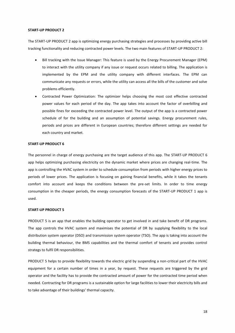
START-UP PRODUCT 2
The START-UP PRODUCT 2 app is optimizing energy purchasing strategies and processes by providing active bill
tracking functionality and reducing contracted power levels. The two main features of START-UP PRODUCT 2:
Bill tracking with the Issue Manager: This feature is used by the Energy Procurement Manager (EPM)
to interact with the utility company if any issue or request occurs related to billing. The application is
implemented by the EPM and the utility company with different interfaces. The EPM can
communicate any requests or errors, while the utility can access all the bills of the customer and solve
problems efficiently.
Contracted Power Optimization: The optimizer helps choosing the most cost effective contracted
power values for each period of the day. The app takes into account the factor of overbilling and
possible fines for exceeding the contracted power level. The output of the app is a contracted power
schedule of for the building and an assumption of potential savings. Energy procurement rules,
periods and prices are different in European countries; therefore different settings are needed for
each country and market.
START-UP PRODUCT 6
The personnel in charge of energy purchasing are the target audience of this app. The START-UP PRODUCT 6
app helps optimizing purchasing electricity on the dynamic market where prices are changing real-time. The
app is controlling the HVAC system in order to schedule consumption from periods with higher energy prices to
periods of lower prices. The application is focusing on gaining financial benefits, while it takes the tenants
comfort into account and keeps the conditions between the pre-set limits. In order to time energy
consumption in the cheaper periods, the energy consumption forecasts of the START-UP PRODUCT 1 app is
used.
START-UP PRODUCT 5
PRODUCT 5 is an app that enables the building operator to get involved in and take benefit of DR programs.
The app controls the HVAC system and maximises the potential of DR by supplying flexibility to the local
distribution system operator (DSO) and transmission system operator (TSO). The app is taking into account the
building thermal behaviour, the BMS capabilities and the thermal comfort of tenants and provides control
strategs to fulfil DR responsibilities.
PRODUCT 5 helps to provide flexibility towards the electric grid by suspending a non-critical part of the HVAC
equipment for a certain number of times in a year, by request. These requests are triggered by the grid
operator and the facility has to provide the contracted amount of power for the contracted time period when
needed. Contracting for DR programs is a sustainable option for large facilities to lower their electricity bills and
to take advantage of their buildings’ thermal capacity.

19
The app is expected to reach an estimated saving of 5% of the yearly energy bill due to the revenues provided
by the DR program.
START-UP PRODUCT 4
The following two applications are developed to reduce energy use in an intelligent way, while the occupants’
comfort level improves. The algorithms behind the applications are based on Machine Learning Techniques and
use occupancy and weather forecast data.
After a systematically executed training period, the START-UP PRODUCT 4 provides optimized schedules for the
optimization of the HVAC system. The application processes the weather forecasts daily and provides
suggestions on how to change HVAC settings as an output. These suggestions are shown on the PRODUCT 4
platform and contain the following information:
An on/off schedule for the next 24 hours of the HVAC.
An on/off schedule for the next 24 hours of free cooling.
Internal temperature set-points schedule.
These abovementioned commands are the schedules for the HVAC system’s different functions. The
modification in the daily HVAC on/off schedule helps setting the optimal start up and shut down of the system
and to decrease the operation hours, while the optimized free cooling schedule contributes to lower cooling
needs in the control zones. Lastly, the schedule of set-points provides the optimal temperatures in each
thermal zone according to the occupancy schedule.
PRODUCT 4 is commissioned if it is not possible to install START-UP PRODUCT 3, the fully automated
application. To follow the recommendations of the app, the personnel in charge need to set up the HVAC
system regularly. As the set up only consists of on/off schedules and temperature set points, it is estimated to
take only 15 minutes a day.
Figure 10 shows the structure of START-UP PRODUCT 4. The measured values are uploaded to the START-UP
cloud. The app consists of a database of building, energy consumption data and the algorithms stored on the
cloud. The algorithms create the schedules and the interface where the commands are made visible for the
building operator.

20
Figure 10 Structure of START-UP PRODUCT 4

21
START-UP PRODUCT 3
The aim of PRODUCT 3 is to reduce energy consumption of the building with automatic HVAC scheduling. The
app is controlling the BMS automatically by sending the following commands directly to the BMS:
An on/off schedule for the next 24 hours of the HVAC
An on/off schedule for the next 24 hours of free cooling
Internal temperature set-points schedule
The process of START-UP PRODUCT 3 is similar to the PRODUCT 4 with the difference of sending the commands
directly to the BMS and overwriting its schedule regularly, instead of offering these schedules as suggestions
for the facility manager.
Figure 11 shows the HVAC set point schedule for the ICAEN building in the PRODUCT 3 app. The HVAC on/off is
in green and the temperature set points are in blue. This schedule is in an hourly resolution and is created on
the night before. This schedule of the building shortened the cooling period by 2 hours by switching the cooling
on later and off earlier than before.
Figure 11 On/off schedule and set-points by START-UP PRODUCT 3

22

23
3 Methodology
The thesis is following the main steps of the practical implementation process of an ECM in a building then
evaluates the results. The audit of the building, the implementation of the ECM, the data collection before and
after the implementation and the calculation of normalised savings are those steps. Besides the verification of
savings due to the START-UP PRODUCT 3 app, the results of START-UP PRODUCT 1 app is also evaluated. Finally
it suggests a business plan for the distribution and selling of the START-UP products.
3.1 Technical audit
First of all, the pilot building is audited. The audit consists of practical and technical considerations as the pilot
project is not expected to generate profits for START-UP or the building owner. In a real project, besides the
technical feasibility, an economical feasibility study is also essential before the implementation of an ECM.
The audit is focusing on the following areas:
3.1.1 Building data
The facility and its energy systems is examined in details before implementing an ECM. The documentations,
the blueprints and the energy consumption data set are provided by the facility manager of the pilot building.
First, the fuel types and energy consumption data are reviewed and the previous year’s consumption data is
collected and examined. The blueprints of the facility that illustrate the electrical, mechanical systems and
construction details are used to identify the main energy consuming machines and to understand the HVAC
system.
Then the presence or the possibility to install thermal sensors is examined. These are used by the BEMS in each
thermal zone to keep the set point temperatures.
After reviewing all the information, the building operator is interviewed to provide practical insights to the
maintenance and occupancy habits, the state of machinery and general condition of the facility and the use of
the BMS and SCADA system. In addition, chillers, boilers, pumps, meters, piping, splits and the air handling
units (AHUs) are documented on photos and in written form indicating their type and performance.
3.1.2 Building Management System
The BMS in the building is examined in details. The START-UP PRODUCT 3 is controlling the HVAC through the
existing Building Management System. In order to send the orders to the BMS, the access and possibilities of
control is checked. The orders of START-UP PRODUCT 3 are related to three main BMS functionalities. The
functionality of using predefined schedules to switch the HVAC on/off, to set temperature set-points in
different zones and to time free-cooling.

24
Additionally, the warranty time of the BMS and other systems are checked because of the risk of losing the
warranty by intervening to the system. Another possible issue is the BMSs protection against third party
intervention by a password. The information to access and connect the BMS system is asked from the facility
manager. If it is not available and the BMS is not accessible, the commissioning may slow down or fail.
3.1.3 HVAC configuration
The relation between AHUs, Fan-coils, rooms and open spaces are examined to make a clear picture of the
overall HVAC system and to set the thermal zones and control zones for START-UP PRODUCT 3. Besides the
zoning, the HVAC communication architecture and the zones with sensors (physical data points) are clarified
for practical reasons in the commissioning.
3.1.4 LAN
The START-UP Energy Controller unit is connected to the BMS through the LAN network of the building. The
access information for the firewall and the permission to set it up is asked from the facility manager. It is
necessary to allow the IP addresses of the hardware to the firewall to allow connection to the internet.
3.1.5 Users’ behaviour
In an office building, with the intention of maintaining the comfort with the commands of START-UP PRODUCT
3, the users’ intervention to the air quality in thermal zones needs to be as minimal as possible. The options for
opening the windows, setting temperature set-points manually in the building are documented.
Lastly, all the data is documented and evaluated to decide on the details of the process of the implementation.
3.2 Implementation
First, as part of the implementation, the Dexma Dexgate data logger and gateway is installed at the site and
connected to the internet to direct energy data to the Dexcell Energy Manager. There are new energy meters
installed in the building as part of the pilot project, although these are not providing continuous data and not
used in this thesis. The data of the energy meters is directed to the Dexcell Energy Manager.
Then, the Energy Controller unit is physically installed and connected to the internet and to the BMS. The
Energy Controller unit is directing schedules downstream from the START-UP servers to the BMS, while the
temperature data of the thermal zones are sent upstream from the BMS to the START-UP cloud. This unit is in
control of the three BMS functions of HVAC on/off, temperature set-points and free cooling on/off.
Third, the data from the local data logger system is directed to the Dexcell Energy Manager. This Circutor
system is gathering data from the electricity meters and gas meter for years and is used for the verification of
energy savings.
Finally the START-UP PRODUCT 3 is trained with the data from the aforementioned three sources. This training
period is necessary to create the energy model of the building in the START-UP servers. The set-point
temperatures are set to different values for four weeks, between 23 and 26 ºC with a step of 1 ºC each week.

25
The energy consumption data, the weather data and the set-point scale is used by the algorithms to create the
building model for the summer period. This training is necessary for the winter period separately.
3.3 Collecting energy data
By the time, the START-UP solution is installed and fully commissioned; the energy consumption data is logged.
The Dexcell Energy Manager is used to monitor the energy consumption day by day to provide reliable data not
only for the M&V process that evaluates the effectiveness of START-UP PRODUCT 3 but for the evaluation of
START-UP PRODUCT 1 forecasted results.
3.4 Regression analysis
The linear regression was studied and used in practice by Legendre in 1805 and by Gauss in 1809 for
determining astronomical observations. However, the term “regression” can be dated back to 1908, when
Francis Galton, British biologist researched the relation between tall parents and tall children.
Regression analysis is a statistical process to estimate any relationship between a dependent variable and other
independent variables. It helps understanding how the dependent variable varies when one of the independent
variables is changed. The regression analysis is used for forecasting effects, forecasting trends or for causality
analysis. The regression can be linear or non-linear. [22]
The two main types of linear regression are; simple linear regression (when there are two variables and the
regression line is straight) and multiple linear regression (when there are more variables and the regression line
is parabolic). [23]
In the energy model of ICAEN building there are two variables available for analysis; energy consumption and
outside temperature. Consequently, the simple linear regression is used for constructing the model.
According to Yan et al. (2009), simple linear regression model can be stated in Eq 1: [23]:
𝑦 = 𝛽0 + 𝛽1𝑥 + 𝜀 Eq 1
𝑦 – Dependent or response variable (Energy consumption)
𝛽0 – Constant or y intercept
𝛽1 – Gradient or slope
𝑥 – Independent or predictor variable (Degree Days)
𝜀 – Random error
26
3.5 Measurement and Verification
The verification of the savings after the first summer months is done following the IPMVP protocol to provide
realistic results of the M&V plan. The M&V option, the boundary, the independent variables, key parameters
and the baseline and reporting period are defined first. The possible interactive effects are examined. Then the
energy use and the historical weather data set are cleaned from the noise and unnecessary data points.
For the comparison of the weather and energy consumption data, the weather data is converted into Degree
Days (DD) and the Base Temperature (BT) is calculated. It is a way to simplify ambient air temperature data,
widely used among energy consultants and energy managers. DD can be used on daily, weekly, monthly or
yearly basis and can be summed together.
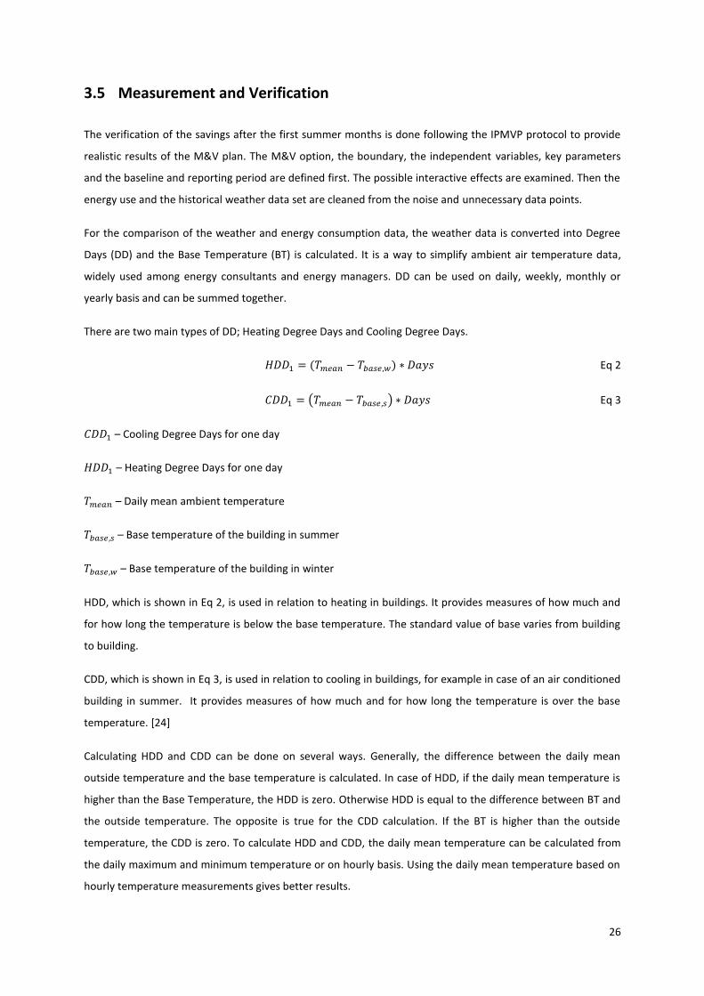
There are two main types of DD; Heating Degree Days and Cooling Degree Days.
𝐻𝐷𝐷1 = (𝑇𝑚𝑒𝑎𝑛 − 𝑇𝑏𝑎𝑠𝑒,𝑤) ∗ 𝐷𝑎𝑦𝑠 Eq 2
𝐶𝐷𝐷1 = (𝑇𝑚𝑒𝑎𝑛 − 𝑇𝑏𝑎𝑠𝑒,𝑠) ∗ 𝐷𝑎𝑦𝑠 Eq 3
𝐶𝐷𝐷1 – Cooling Degree Days for one day
𝐻𝐷𝐷1 – Heating Degree Days for one day
𝑇𝑚𝑒𝑎𝑛 – Daily mean ambient temperature
𝑇𝑏𝑎𝑠𝑒,𝑠 – Base temperature of the building in summer
𝑇𝑏𝑎𝑠𝑒,𝑤 – Base temperature of the building in winter
HDD, which is shown in Eq 2, is used in relation to heating in buildings. It provides measures of how much and
for how long the temperature is below the base temperature. The standard value of base varies from building
to building.
CDD, which is shown in Eq 3, is used in relation to cooling in buildings, for example in case of an air conditioned
building in summer. It provides measures of how much and for how long the temperature is over the base
temperature. [24]
Calculating HDD and CDD can be done on several ways. Generally, the difference between the daily mean
outside temperature and the base temperature is calculated. In case of HDD, if the daily mean temperature is
higher than the Base Temperature, the HDD is zero. Otherwise HDD is equal to the difference between BT and
the outside temperature. The opposite is true for the CDD calculation. If the BT is higher than the outside
temperature, the CDD is zero. To calculate HDD and CDD, the daily mean temperature can be calculated from
the daily maximum and minimum temperature or on hourly basis. Using the daily mean temperature based on
hourly temperature measurements gives better results.

27
The Base Temperature is the ambient temperature above which the heating or below the cooling of the
building is necessary. The typical value needs to be determined for each building separately for the cooling and
the heating season. The value of BT depends on the building inertia, climate, solar irradiation, type of use,
comfort temperature or even on the environment it is built. To determine the corresponding BT, the DDs are
calculated and the regression analysis is conducted with different BT values. To have the best correlation
between energy use and outside temperature, the most realistic BT needs to be used. This can be decided by
picking the highest Coefficient of Determination value in a practical interval.
The coefficient of determination, also called R2, is a number that shows the proportion of change in the
response (dependent) variable that is anticipated from the predictor (independent) variable. It is used in
relation to statistical models, where the main purpose is to predict some future outcome or test hypotheses.
The coefficient provides information about the goodness of fit of a model, how close is the regression line to
the data points. “With linear regression, the coefficient of determination is also equal to the square of the
correlation between x and y scores.” [21] R2 is between 0 and 1, where 1 is the ideal match and 0 means that
the dependent variable cannot be predicted.
In case of energy modelling with linear regression, the energy consumption is related to the DD in the heating
or cooling season. The DD and the consumption are plotted on a chart in Microsoft Excel. The software offers
the option to create the regression line on the chart and to calculate the simple regression model with the
coefficient of determination.
Afterwards, the resultant regression equation is used to normalize the energy consumption to a fixed period
previous the baseline period. The normalized energy savings then are translated into CO2 and into financial
benefits.

28

29
4 Case studies
In the BEEST project there are four pilot projects to test the START-UP applications. There are hotels and
offices, buildings using only electricity or also natural gas, located in different climates and environment in
Europe. The ICEAN building is the main pilot project for START-UP PRODUCT 3 and the measurement and
verification plan is done for this building; therefore its quantities are explained in details. The other buildings
are also used to gather data and experience on commissioning other apps.
4.1 ICAEN Building
The building belongs to the Departament d’Empresa i Ocupació de la Generalitat de Catalunya and provides
office area for four institutions: Direcció General d’Energia, Mines i Seguretat Industrial, Institut Català
d’Energia (ICAEN) and Agència Catalana de Consum. As it can be seen on Figure 12, the building is part of a
multipurpose urban complex including apartments and offices.
Figure 12 Photo of ICAEN building [25]
The building was built in 2008 and it is in service since 2009. The total area of the building is 9157 m2, where
8362 m2 is air conditioned. Besides the ground floor, there are four floors above ground for offices and two
basement floors for archives, warehouses and technical areas. The fourth floor has smaller area compared to
the other floors. Also, there is a four floor high atrium at the main entrance that can be ventilated or air
conditioned.
The horizontal shades against the solar irradiation on the Northern and Southern facades on Figure 13.

30
Figure 13 Shades on the façade on the left and entrance with the atrium on the right in ICAEN
Figure 14 shows a blueprint of the ICAEN building and the surroundings. As it is visible, the entrance is from in
the inner garden of the complex.
Figure 14 Position of ICAEN building [25]
HVAC System
The ICAEN office is equipped with a Building Management System (BMS) by SAUTER implemented in 2009. The
BMS is handling the illumination, the heating, ventilation and air conditioning (HVAC) and the security system.
Later, for the sake of the pilot project, the Dexcell Energy Manager platform provided by Dexma was installed.
The platform works as Software-as-a-service (SaaS), gathering information from the building. Additionally,
there is an energy monitoring system by CIRCUTOR, a company specialized on BMS solutions, collecting
information from meters and sensors and transmitting it to the BMS.

31
Table 1 shows the two chillers and two boilers providing the cooling and the heating for the building. The hot
water is produced with two ADISA Duplex 399 condensing boilers with the thermal performance of 417 kWth.
The cold water production is based on a pair of TRANE ECGAN 214 chillers with the thermal performance of
462kWth. Additionally, there are several Mitsubishi split units in the building; however they are not in the scope
of the project.
Table 1 Chillers and Boilers in ICAEN building
Task Type Thermal
Performance Number
Chillers TRANE CGAN
214 461.8 kWth 2 pcs
Boilers ADISA
Duplex 399 417 kWth 2 pcs
The scheme of the hot water production system from the SCADA is shown on Figure 15. On the left hand side
the two boilers are visible that produce the hot water and with the help of six pumps (on the bottom) the
water is directed to the following units:
Air Handling Units: CL-1, CL-2, CL-3
Air Handling Unit: CL-4
Fan-coils
Figure 15 Scheme of boilers in ICAEN

32
The photo of Figure 16 is taken of one of the boilers in the office building. There are two ADISA condensing
boilers providing the hot water placed next to each other.
Figure 16 Photo of one of the boilers on the top floor of the ICAEN office
The scheme of the cold water production system from the SCADA is shown on Figure 17. The cold water is
produced by the two chillers (on the right), then with the help of six pumps (on the bottom) the water is
directed to the following units:
Air Handling Units: CL-1, CL-2, CL-3
Air Handling Unit: CL-4
Fan-coils

33
Figure 17 Scheme of chillers in ICAEN
Figure 18 is taken of one of the chillers in the office building. There are two similar chillers placed next to each
other providing the cold water for air conditioning.
Figure 18 Photo of one of the chillers in ICAEN
There are four Air Handling Units (AHUs) in the building. Two of them (CL-1 and CL2-) are responsible to
provide preheated or pre-cooled air to the offices. The preheated or pre-cooled air from CL-1 and CL-2 is
distributed with air ducts in every floor in the false sealing. Then the fan-coils installed in the false ceiling
temper this preheated or pre-cooled air to the set-point temperatures and introduce it to the office rooms. It is

34
shown on Table 2 that the AHU CL-3 is providing tempered fresh air directly for the atrium and the ground
floor, while the forth CL-4 has the same duty for the file storage space underground.
Table 2 Air Handling Units in ICAEN
Air Handling Unit Zones Heating
Performance Cooling
Performance
CL-1 Floor 1,2,3,4 92.5 kWth 122.1 kWth
CL-2 Floor 1,2,3,4 61.8 kWth 83.8 kWth
CL-3 Atrium and
ground 36.3 kWth 45.5 kWth
CL-4 Archive 35.9 kWth 55.9 kWth
As it can be seen on Figure 19, the office rooms are located along the facade, while the elevators are in the
middle of the building. There are four thermal zones on each of the first, second, third and fourth floors. These
thermal zones are called L1, L2, L3 and L4 in every floor. The AHU CL-1 is providing air to the L1 and L2 thermal
zones, while CL-2 is providing air to the L3 and L4. The AHU CL-3 is responsible for the atrium and the ground
floor, CL-4 is for the Archive space.
Figure 19 Blueprint of the third floor in ICAEN building [25]
4.2 Av. Roma 25
The building is situated in the heart of Barcelona at Av. Roma 25. The building functions as the office of Comsa
Corporación and Comsa Service. As the Comsa Group is highly involved in the development of the suite of apps,
the company offered its facility to be a pilot project and to test the applications. The building is visible on Figure
20.

35
Figure 20 Comsa office at Av. Roma 25, Barcelona [26]
The building’s area is 2636 m2 and has 7 floors. The building uses electricity for heating and cooling. There are
fourteen Air Handling Units in the building and the total cooling performance is 574 kW while the heating
performance is 640 kW.
The Dexcell Energy Manager platform monitors the electricity consumption of the building and the START-UP
PRODUCT 1 is providing 48 hour energy forecasts.
4.3 NH Waalwijk
Figure 21 NH Waalwijk [26]
The NH Waalwijk Hotel is shown on Figure 22. It is situated in Waalwijk, The Netherlands. The BMS installed is
Siemens Desigo Insight while the DEXCell Energy Manager is installed for energy monitoring.

36
There are three condensing boilers for heating (3x185 kW) and two other (230 kW) for DHW production. Three
AHUs are installed in the building. One for the common areas and the restaurant, the second is for the kitchen
and the last one is providing heating or cooling for the meeting rooms. The heating need of the rooms is
satisfied by radiators, while there are split units for cooling.
4.4 De Lijn Gentbrugge
Figure 22 De Lijn Gentbrugge [26]
The De Lijn building in Gentbrugge was built in 1980 and it was renovated in 2005. There are two wings of the
building; one is from 1980 and the other is from the year of renovation.
There are two condensing boilers (270 kWh_th each) in the building. The hot water from the boilers are
directed into two directions; First the air is preheated in the two AHUs on the building, second the water is sent
to the climate bars to reheat the air from the AHUs before it is entering the rooms. Besides the heating
provided by the AHUs, there are radiators on each floor.
In the cooling season two chillers are providing cold water for the AHUs. The cold water then sent to the
climate bars to cool down the air entering to the rooms. Besides the cooling provided by the AHUs, there are
two split units that serve the air-conditioning of the server rooms.
The building has temperature sensors on every floor and a SCADA is visualizing the HVAC in details.

37

38
5 Results
5.1 Measurement and Verification in ICAEN building
The ICAEN building is the first pilot project for commissioning and testing START-UP PRODUCT 3, the app which
provides automated control over the BMS. PRODUCT 3 is being tested, while START-UP PRODUCT 1, the app
that forecasts energy consumption on hourly resolution, is functioning. To verify the savings reached by the
START-UP PRODUCT 3, the Measurement and Verification plan is created according to the IPMVP protocol.
The Measurement and Verification plan is defined for this building to test the energy savings of the START-UP
PRODUCT 3 application. The basic points and requirements of M&V planning are listed then the energy
consumption data used is introduced.
M&V Option and boundary
First, Option C is justified as the PRODUCT 3 is installed on top of the existing BMS and manages the complete
HVAC system that consists of several Air Handling Units (AHUs) and is present in most of the sections of the
building. Also, the ECM is intended to reach more than 10% energy savings that satisfies the requirement of the
minimum 10% energy saving posed by the IPMVP protocol. The energy consumption of the chillers and boilers
is measured directly with gas and electric meters; consequently no other consumption affects the
measurements.
The BEMS affects the HVAC in the whole facility, regardless floors and zones. Accordingly, the boundary of the
M&V project is set as the chillers and boiler units of the HVAC system. Measurements take into account that
the energy needed for pumps and other peripheral equipment are independent of the cooling or heating loads.
These peripheral consumptions create a base load and are excluded from the metering.
Interactive Effects
In the case of ICAEN pilot project there is no interactive effect due to the direct electricity metering before the
chillers and the fact that the boilers used for heating are the only gas consumers. The effect of the lighting is
very low due to the LED based system.
Key parameters
The key parameters are energy consumption of the boilers and chillers. The energy consumption is compared
to the ambient temperature and provides the correlation for the energy model.
Independent variables
The following independent variables were considered and used or discarded from the analysis:
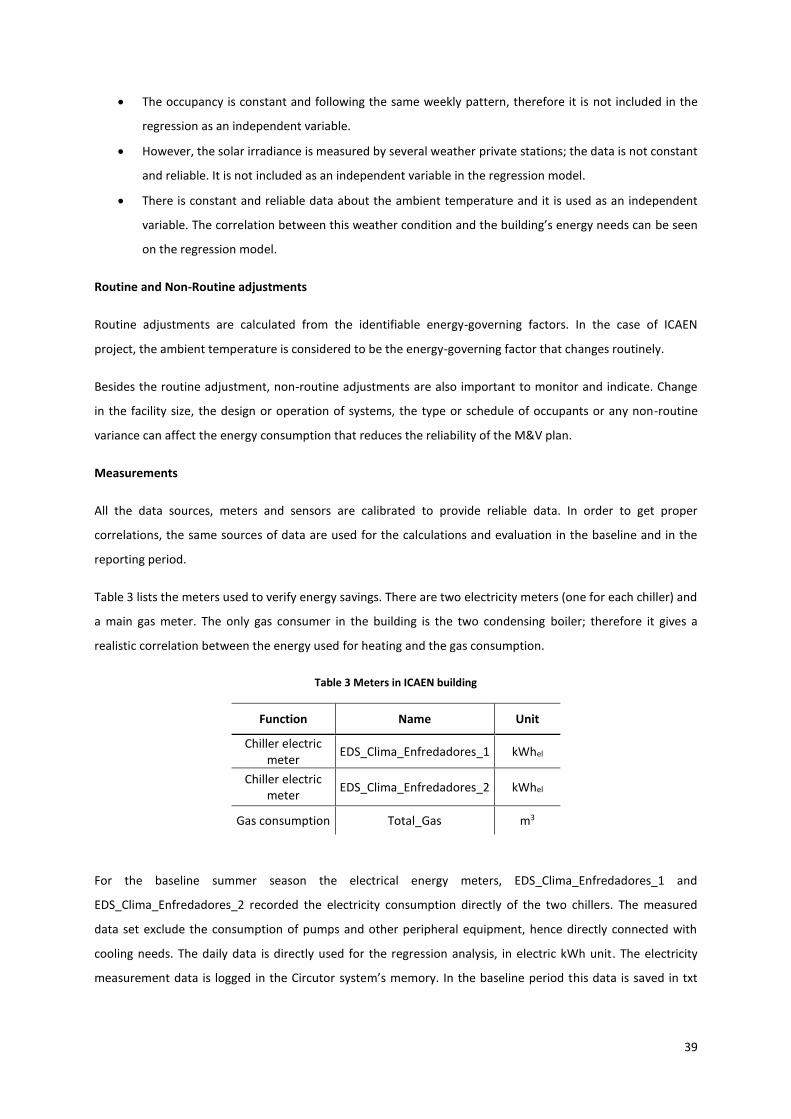
39
The occupancy is constant and following the same weekly pattern, therefore it is not included in the
regression as an independent variable.
However, the solar irradiance is measured by several weather private stations; the data is not constant
and reliable. It is not included as an independent variable in the regression model.
There is constant and reliable data about the ambient temperature and it is used as an independent
variable. The correlation between this weather condition and the building’s energy needs can be seen
on the regression model.
Routine and Non-Routine adjustments
Routine adjustments are calculated from the identifiable energy-governing factors. In the case of ICAEN
project, the ambient temperature is considered to be the energy-governing factor that changes routinely.
Besides the routine adjustment, non-routine adjustments are also important to monitor and indicate. Change
in the facility size, the design or operation of systems, the type or schedule of occupants or any non-routine
variance can affect the energy consumption that reduces the reliability of the M&V plan.
Measurements
All the data sources, meters and sensors are calibrated to provide reliable data. In order to get proper
correlations, the same sources of data are used for the calculations and evaluation in the baseline and in the
reporting period.
Table 3 lists the meters used to verify energy savings. There are two electricity meters (one for each chiller) and
a main gas meter. The only gas consumer in the building is the two condensing boiler; therefore it gives a
realistic correlation between the energy used for heating and the gas consumption.
Table 3 Meters in ICAEN building
Function Name Unit
Chiller electric meter
EDS_Clima_Enfredadores_1 kWhel
Chiller electric meter
EDS_Clima_Enfredadores_2 kWhel
Gas consumption Total_Gas m3
For the baseline summer season the electrical energy meters, EDS_Clima_Enfredadores_1 and
EDS_Clima_Enfredadores_2 recorded the electricity consumption directly of the two chillers. The measured
data set exclude the consumption of pumps and other peripheral equipment, hence directly connected with
cooling needs. The daily data is directly used for the regression analysis, in electric kWh unit. The electricity
measurement data is logged in the Circutor system’s memory. In the baseline period this data is saved in txt

40
files and difficult to manage, while in the reporting period, the Circutor system is forwarding the logged data to
the Dexcell Energy Manager that is providing an easier data management.
For the heating season, the gas meter “Total_Gas” is used as the heating system is the only gas consumer in the
building. The log of the measurements is stored in the Circutor system in the baseline period. Later, it is
directed to the Dexcell Energy Manager in the reporting period.
Defining Baseline period
On Figure 23 the energy consumption of the chillers in the baseline period is shown in electric kWh and the gas
consumption of the boilers are shown in cubic meters. The baseline period is considered from the 1st of May
2015 until the 30th April 2016, while the reporting period is the one year period after the implementation of
the ECM.
Figure 23 Energy consumption of heating and cooling in the baseline period
It is visible on Figure 23 that in October and May of the baseline period there is no significant heating or cooling
need. It is also visible that in the months of November and April there is a mix of cooling and heating. This
phenomenon is due to the big difference in daily minimum and maximum temperatures [27]. As a consequence
May, October, November and April are considered to be transitional months. In the regression analysis the
regression equation is determined using June, July, August and September for the summer season, while the
December, January, February and March for the heating season. However the regression equation is calculated
in both seasons based on four months, the normalized energy savings for the transitional period are calculated
assuming the same thermal behaviour.
Normalized energy savings
The normalized energy savings method is a practical way to examine the energy consumption of a building in
different periods and weather conditions. Due to the type of data and resources available, the Degree Days
0
500
1000
1500
2000
2500
1.5
.20
15
14
.5.2
01
5
27
.5.2
01
5
9.6
.20
15
22
.6.2
01
5
5.7
.20
15
18
.7.2
01
5
31
.7.2
01
5
13
.8.2
01
5
26
.8.2
01
5
8.9
.20
15
21
.9.2
01
5
4.1
0.2
01
5
17
.10
.20
15
30
.10
.20
15
12
.11
.20
15
25
.11
.20
15
8.1
2.2
01
5
21
.12
.20
15
3.1
.20
16
16
.1.2
01
6
29
.1.2
01
6
11
.2.2
01
6
24
.2.2
01
6
8.3
.20
16
21
.3.2
01
6
3.4
.20
16
16
.4.2
01
6
29
.4.2
01
60,0
100,0
200,0
300,0
400,0
500,0
600,0
CH
ILLE
R K
WH
_EL
BO
ILER
M3
GA
S

41
(DD) method is applied in the analysis. In the normalizing process the use of fine weather data, properly chosen
base temperature and carefully handled data is required to have satisfying results.
Weather stations
For calculating the DD, accurate weather data is crucial. In most of the cases, buildings do not have their own
weather stations. For this reason, it is important for the energy saving calculations to look for other weather
data sources.
Ideally, the closest weather station with available data provides the most accurate data for the building being
analysed. However, data quality and coverage are the most important features of data sets that need
consideration. Generally, weather stations of airports have free and high quality data sets.
In the case of the ICAEN building, the weather station of the El Prat Airport is 17 km away. While the building is
in the city surrounded with blocks of flats and offices, the airport is outside of the city without any
surroundings. Therefore, the personal stations in the neighbourhood are considered instead of the airport.
After examining several options, the IBARCELO253 weather station proves to have the most coherent and
realistic data from the same environment. The position of the station is shown by Figure 24. It is approximately
600 meters away from the ICAEN building and has enough historical data for the energy analysis.
Figure 24 The location of the weather station and the ICAEN office [26]
Base temperature for summer
The BT is chosen for the building for the cooling season based on the historical energy consumption. The
following diagram shows the R2 values for different base temperature in summer.

42
Figure 25 R2 values for different Base Temperatures
It is visible on Figure 25 that the highest R2 value is above 0.78 at 20 °C. This BT value is the highest; therefore
used for the summer analysis.
Linear regression analysis for summer
In summer, the regression analysis is calculated for the Cooling Degree Days (CDD) and the electricity
consumption. Only weekdays are taken into account in the regression analysis as the office is out of use on the
weekends. Table 4 shows the official local and national holidays that are removed from the dataset in order to
improve the accuracy of the energy model.
Table 4 Number of removed holidays
Month Holidays removed
January 2
March 2
June 2
September 2
October 1
December 3
Determining the relation between the weather conditions and the energy consumption is an iterative process.
The CDDs and electricity consumption of every day of the summer period are listed and different techniques
are tried in order to find the best correlation and to find the highest R2 value.
First, all the seven days of the week is used to determine the correlation. Using these data gives a poor
correlation of R2=0.4. The main reason for the poor results are the fact that the office is out of use on the
weekends, the energy use is close to zero on Saturday and Sunday.
0,690
0,700
0,710
0,720
0,730
0,740
0,750
0,760
0,770
0,780
0,790
19 19,5 20 20,5 21 21,5 22 22,5
R2
BASE TEMPERATURE [ºC]
R2

43
Finally, only the weekdays are used in the process and weekends are neglected. This approach gives much
higher R2 value. After removing the holidays and wrong data points, the highest regression value is R2=0.78.
This is above the minimum of R2=0.75 suggested by the IPMVP protocol and can be considered as satisfactory.
The linear regression in the summer period can be seen on Figure 26. The electricity use of the chillers and the
CDDs are compared and the Coefficient of Determination with the regression equation is visible.
Figure 26 Linear regression analysis for CDD and electricity consumption
The result of the regression analysis is shown as Eq 4. This equation is used for normalising the baseline
summer period.
y = 151.78x + 343.99 Eq 4
𝑅2 = 0.7844
Linear regression analysis for winter
After examining the winter data set, one can conclude that the relation between HDDs and heating energy
consumption is not logical. In other words, the energy used according to the gas meter for heating is not
correlated with the outside temperature. However the data set gives a positive slope, the regression analysis
on daily basis provides the value of R2=0.1 that is unacceptably low.
y = 151,78x + 343,99R² = 0,7844
0
500
1000
1500
2000
2500
0,00 2,00 4,00 6,00 8,00 10,00 12,00 14,00
Ch
ille
r e
lect
rici
ty c
on
sum
pti
on
[kW
he
l]
Cooling Degree Days
Electricity consumption Linear

44
These results of the regression analysis based on daily HDDs and energy consumption can be seen on Figure 27.
Figure 27 Regression analysis for HDD and gas consumption on daily basis
On Figure 27 another approach is shown where the monthly consumption data is compared to the monthly
sum of HDDs. After summing up the daily data to each month, the regression line has the negative slope. It
implies that there is less energy used for heating on colder days and it is unacceptable.
Figure 28 Regression analysis for HDD and gas consumption on monthly basis
To address this problem and find out the reasons behind the low quality data set, the maintenance staff is
asked to do a comprehensive test and check the HVAC system in the building.
y = 219,14x + 2077R² = 0,096
0,00
1000,00
2000,00
3000,00
4000,00
5000,00
6000,00
7000,00
0,00 1,00 2,00 3,00 4,00 5,00 6,00 7,00 8,00 9,00
Bo
iler
gas
con
sum
pti
on
[kW
hth
]
Heating Degree Days
Gas consumption Linear
y = -1720,9x + 196484R² = 0,7803
0,00
10000,00
20000,00
30000,00
40000,00
50000,00
60000,00
70000,00
80000,00
74,00 76,00 78,00 80,00 82,00 84,00 86,00
Bo
iler
gas
con
sum
pti
on
[kW
hth
]
Heating Degree Days
Gas consumption Linear

45
After checking the status of each fan-coil in detail, it is concluded that several sensors and valves are out of
order. There are 75 fan-coils in the system and 20 out of them have no or false temperature data. Also, the
valves are not set properly in many cases. As a result of the unveiled issues, the interference between cooling
and heating is also possible if the temperature sensors are sending false data.
As a result of the low quality data set, the savings of the ECM cannot be calculated for winter with this
approach.
Normalized energy consumption
Normalization is a process that makes the comparison of different years’ data possible. Normalizing energy
data to fixed conditions is necessary to calculate normalized energy savings. There are two ways of fixing
conditions for calculating normalized savings; to use the conditions of the baseline period or use a period
before the baseline. In order to increase the quality of the weather normalization, a longer period’s average
can be used.
First, in the weather normalization process the weather data between 2013 and 2015 is used. The average
number of CDDs and HDDs in each month is determined from the data set. Also, the average number of
weekdays of these months is filtered from the eleven year-long period.
Then, the regression equation of the reporting period is determined using the same base temperature for the
DD as in the baseline period. Eq 5 is the regression equation in the reporting period. It does not give the same
R2=0.78 value as the baseline period, only R2=0.70, that increases the uncertainty in the calculations.
y = 151,5x + 301,03 Eq 5
𝑅2 = 0.7031
The CDDs and number of days are multiplied by the baseline and reporting periods’ equations’ fixed and load
sensitive components. These equations are following the consumption pattern and embody the behaviour of
the HVAC in the given period; therefore by introducing the days and CDDs of the fixed period, the result is the
normalized energy consumption.
On Table 5, only the summer months are shown. The normalised savings cannot be calculated in the winter
period due to the lack of reliable data. On the left, the average number of weekdays and the sum of CDDs in
the fixed period is shown, then the fixed and the load sensitive components of each period. Finally, the
normalised savings are visible in each month and summed up on the bottom.
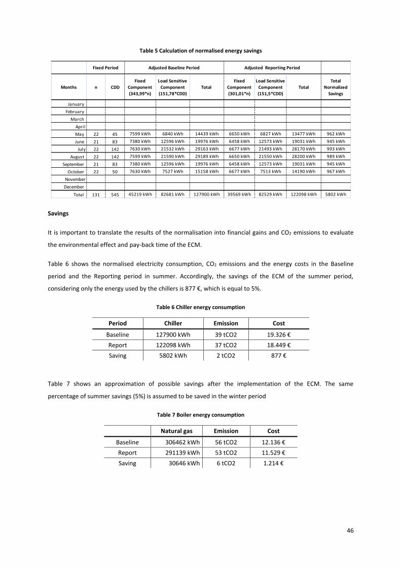
46
Table 5 Calculation of normalised energy savings
Savings
It is important to translate the results of the normalisation into financial gains and CO2 emissions to evaluate
the environmental effect and pay-back time of the ECM.
Table 6 shows the normalised electricity consumption, CO2 emissions and the energy costs in the Baseline
period and the Reporting period in summer. Accordingly, the savings of the ECM of the summer period,
considering only the energy used by the chillers is 877 €, which is equal to 5%.
Table 6 Chiller energy consumption
Period Chiller Emission Cost
Baseline 127900 kWh 39 tCO2 19.326 €
Report 122098 kWh 37 tCO2 18.449 €
Saving 5802 kWh 2 tCO2 877 €
Table 7 shows an approximation of possible savings after the implementation of the ECM. The same
percentage of summer savings (5%) is assumed to be saved in the winter period
Table 7 Boiler energy consumption
Natural gas Emission Cost
Baseline 306462 kWh 56 tCO2 12.136 €
Report 291139 kWh 53 tCO2 11.529 €
Saving 30646 kWh 6 tCO2 1.214 €
Months n CDD
Fixed
Component
(343,99*n)
Load Sensitive
Component
(151,78*CDD)
Total
Fixed
Component
(301,01*n)
Load Sensitive
Component
(151,5*CDD)
Total
Total
Normalized
Savings
January
February
March
April
May 22 45 7599 kWh 6840 kWh 14439 kWh 6650 kWh 6827 kWh 13477 kWh 962 kWh
June 21 83 7380 kWh 12596 kWh 19976 kWh 6458 kWh 12573 kWh 19031 kWh 945 kWh
July 22 142 7630 kWh 21532 kWh 29163 kWh 6677 kWh 21493 kWh 28170 kWh 993 kWh
August 22 142 7599 kWh 21590 kWh 29189 kWh 6650 kWh 21550 kWh 28200 kWh 989 kWh
September 21 83 7380 kWh 12596 kWh 19976 kWh 6458 kWh 12573 kWh 19031 kWh 945 kWh
October 22 50 7630 kWh 7527 kWh 15158 kWh 6677 kWh 7513 kWh 14190 kWh 967 kWh
November
December
Total 131 545 45219 kWh 82681 kWh 127900 kWh 39569 kWh 82529 kWh 122098 kWh 5802 kWh
Fixed Period Adjusted Baseline Period Adjusted Reporting Period
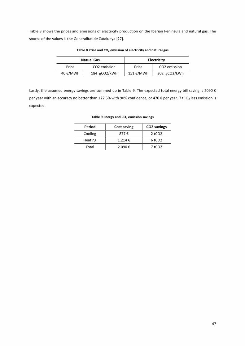
47
Table 8 shows the prices and emissions of electricity production on the Iberian Peninsula and natural gas. The
source of the values is the Generalitat de Catalunya [27].
Table 8 Price and CO2 emission of electricity and natural gas
Natual Gas Electricity
Price CO2 emission Price CO2 emission
40 €/MWh 184 gCO2/kWh 151 €/MWh 302 gCO2/kWh
Lastly, the assumed energy savings are summed up in Table 9. The expected total energy bill saving is 2090 €
per year with an accuracy no better than ±22.5% with 90% confidence, or 470 € per year. 7 tCO2 less emission is
expected.
Table 9 Energy and CO2 emission savings
Period Cost saving CO2 savings
Cooling 877 € 2 tCO2
Heating 1.214 € 6 tCO2
Total 2.090 € 7 tCO2
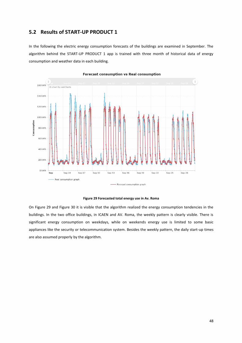
48
5.2 Results of START-UP PRODUCT 1
In the following the electric energy consumption forecasts of the buildings are examined in September. The
algorithm behind the START-UP PRODUCT 1 app is trained with three month of historical data of energy
consumption and weather data in each building.
Figure 29 Forecasted total energy use in Av. Roma
On Figure 29 and Figure 30 it is visible that the algorithm realized the energy consumption tendencies in the
buildings. In the two office buildings, in ICAEN and AV. Roma, the weekly pattern is clearly visible. There is
significant energy consumption on weekdays, while on weekends energy use is limited to some basic
appliances like the security or telecommunication system. Besides the weekly pattern, the daily start-up times
are also assumed properly by the algorithm.

49
Figure 30 Forecasted total energy use in ICAEN
It is visible on Figure 29 and Figure 30 that the maximum energy needs forecasted are different in many days.
The error of the forecasted values compared to the real values is 20.3% in Av. Roma and 30.4% in ICAEN on an
hourly basis, while 13.3% and 11.9% respectively on a daily basis. Considering the sum of these values for the
month, the error is 5% in Av. Roma and 1.8% at the ICAEN building.

50
Figure 31 Forecasted HVAC energy use in ICAEN
Besides the total electric energy consumption, the HVAC energy consumption is forecasted in the ICAEN
building. As seen on Figure 31, the forecast of HVAC energy consumption is following the weekly trend,
however the hourly energy forecast has an average error close to 400%, while 42% error in the daily values.
Considering the error of the monthly energy use, it is 3.6%, which is a significantly lower value compared to the
hourly and daily error.
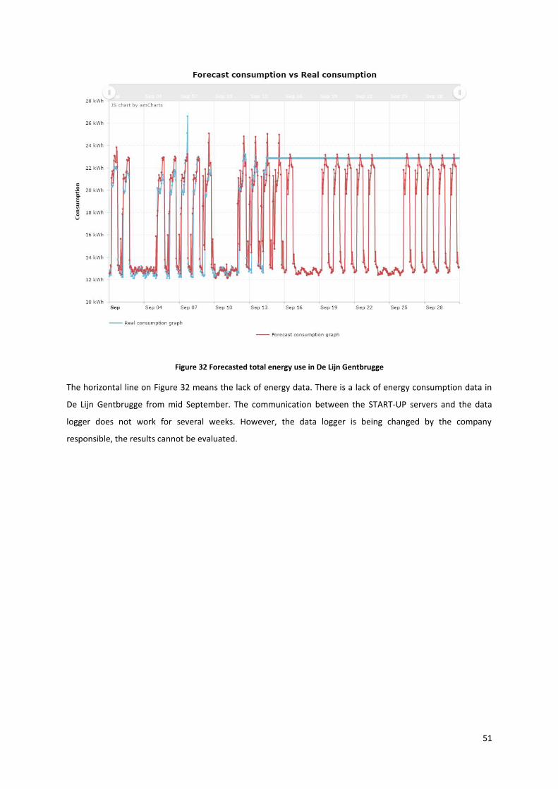
51
Figure 32 Forecasted total energy use in De Lijn Gentbrugge
The horizontal line on Figure 32 means the lack of energy data. There is a lack of energy consumption data in
De Lijn Gentbrugge from mid September. The communication between the START-UP servers and the data
logger does not work for several weeks. However, the data logger is being changed by the company
responsible, the results cannot be evaluated.

52
Figure 33 Forecasted total energy use in NH Waalwijk
In addition to De Lijn Gentbrugge, the results in NH Waalwijk visible on Figure 33 cannot be evaluated either.
Due to the failure of the data logger, the energy use data between the 2nd and the 15th of September is missing.
The company responsible for maintenance restarted the electricity meter on the 15th of September. The START-
UP PRODUCT 1 started forecasting on the 22nd September again.
The summary of the results is shown on Table 10.
Table 10 Summary of PRODUCT 1 errors
Av. Roma ICAEN NH Waalwijk Gentbrugge
Hourly 20.3% 30.4% - -
Daily 13.3% 11.9% - -
Monthly 5% 1.8% - -

53

54
6 Business plan for Partners
Real estate companies, ESCOs and facility managers are continuously fighting to comply with soaring energy
bills in hotels and office buildings, while it is essential to maintain the comfort level for their customers. By
implementing the START-UP suit of apps, that helps reducing energy bills, these companies can make a step
forward to generate higher profits in the very competitive field of facility management.
The START-UP suit of apps can reduce energy bills up to 20% by offering innovative solutions, like:
Increased energy awareness.
Optimized energy purchasing strategies.
Automated HVAC scheduling.
Exploit the opportunities of demand response programs.
Access the electricity wholesale market.
Partners of START-UP are eligible to sell and commission the suit of apps and make significant profit on various
ways.
6.1 Partnership with START-UP
Partners of START-UP are companies that sell, install and put START-UP Building Energy Management System
apps into operation. In exchange for these services, Partners receive incomes from the customers, the end-
users.
6.1.1 Requirements for Partners
Future Partners need to fulfil the following conditions:
Have experience in office or hotel building auditing.
Can integrate hardware, software and complete solutions in offices, hotels.
Have experience in BMS and HVAC commissioning.
Have the potential and capacity to reach a great number of customers.
Commissioning the BEMS is different in every office or hotel building. A high level of proficiency is desired from
the Partner; therefore START-UP provides training related to the install and use of START-UP hardware and
software. The training equips Partners with the knowledge needed to commission the specific applications.
After the training, Partners are capable of auditing and commissioning the START-UP apps independently. For
further issues with START-UP products the support of START-UP is available.
6.1.2 Benefits of being a Partner
eQuialtiq provides Partners with the following benefits:
Direct income from selling the START-UP solutions.

55
Selling an innovative product without investing in R&D.
Access to the market of smart technologies.
Access to new customers with sophisticated needs.
Improved visibility and reputation by the industry.
6.1.3 Potential Partners
In this section an evaluation of potential and future Partners can be found. The first Partners of START-UP are
companies involved in the BEEST project, in which the suit of apps is developed. Later, Partners from every
corner of Europe are welcome to sell START-UP products.
Comsa Service
Comsa Service is part of the Comsa Group. The company is already involved in the BEEST project that is
developing the products of START-UP. This department of the Comsa Group is involved in the ICAEN and other
pilot projects in Barcelona, responsible for installing and commissioning the START-UP applications. It involves
the installation of sensors, meters, the responsibility of the training the software, communicating results, etc.
The wide variety of services and experience makes Comsa Service to be an ideal Partner of START-UP:
Comprehensive and specialized maintenance: Comsa Service offers multidisciplinary maintenance for
a wide range of applications, like technological and technical consulting or regular, preventive,
predictive, corrective maintenance.
Facility management: This company offers services related to operational management of fixed assets,
such as offices, museums, shopping centers and industrial facilities.
Maintenance engineering: They conduct technical audits in order to diagnose malfunctions of
facilities, and energy audits to review compliance with different energy and safety regulations.
Conduct feasibility studies for the implementation of projects.
Energy Service Company (ESCO): Comsa Services is involved in energy efficiency projects as an ESCO,
providing services such as design, financing, and execution of installations, energy management and
maintenance [28].
Enervalis
Enervalis is specialized on decentralized, scalable and secure SaaS middleware solutions, used for electric
vehicle, smart building and Micro-grid projects. Enervalis is a shareholder of START-UP and owns skills that
make them a Partner of START-UP, too. Enervalis has the following responsibilities with two pilot projects in
Belgium:
Installing energy meters and sensors to existing HVAC systems.
Integrating the Dexma DEXCell Energy Management software.
Commissioning of gateways, making communication with the cloud system possible.
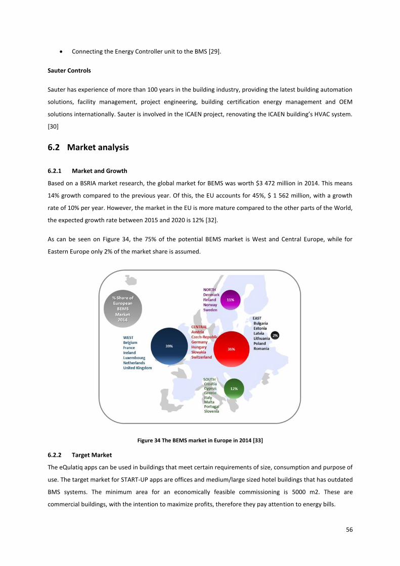
56
Connecting the Energy Controller unit to the BMS [29].
Sauter Controls
Sauter has experience of more than 100 years in the building industry, providing the latest building automation
solutions, facility management, project engineering, building certification energy management and OEM
solutions internationally. Sauter is involved in the ICAEN project, renovating the ICAEN building’s HVAC system.
[30]
6.2 Market analysis
6.2.1 Market and Growth
Based on a BSRIA market research, the global market for BEMS was worth $3 472 million in 2014. This means
14% growth compared to the previous year. Of this, the EU accounts for 45%, $ 1 562 million, with a growth
rate of 10% per year. However, the market in the EU is more mature compared to the other parts of the World,
the expected growth rate between 2015 and 2020 is 12% [32].
As can be seen on Figure 34, the 75% of the potential BEMS market is West and Central Europe, while for
Eastern Europe only 2% of the market share is assumed.
Figure 34 The BEMS market in Europe in 2014 [33]
6.2.2 Target Market
The eQulatiq apps can be used in buildings that meet certain requirements of size, consumption and purpose of
use. The target market for START-UP apps are offices and medium/large sized hotel buildings that has outdated
BMS systems. The minimum area for an economically feasible commissioning is 5000 m2. These are
commercial buildings, with the intention to maximize profits, therefore they pay attention to energy bills.

57
Due to the presence of the START-UP shareholders and first partners in the same time, the first target markets
are Spain and Belgium. However, the PRODUCT 3 and the PRODUCT 1 application are possible to be used in any
building that meet the basic requirements, which means that in the future Partners in any country may appear.
6.2.3 Competitor Analysis
There are numerous companies offering services and products for the same customer segment. Some of them
are offering complete solutions including self-branded hardware, while there are companies offering SaaS. The
market is expanding rapidly and besides the key vendors, some start-ups are also getting a share on the
market. In the following, some of the companies and their products are examined. [23], [31]
BuildingIQ
BuildingIQ was founded in 2009 in Australia and now has offices in the USA as well. Among others, Siemens and
Schneider Electric are investors in the company. The main product of the company is a software that
automates and optimizes the HVAC system.
The main functionalities and services that the company offers are:
HVAC automation
Analyzing demand response capacities
Participation in demand response programs
Automated Measurement and Verification calculation
HVAC schedules 24 hours in advance
Building portfolio management for facility managers
Comfort complaint management
One day energy consumption forecast of HVAC
Remote control for HVAC
The company offers a fast implementation scaling around 5 weeks and compatibility with most of the BMS
systems. The main focus of the products are office buildings. BuildingIQ has 10 to 50 employees and tracks 1.8
million m2 area of commercial buildings [31].
One of the competitive advantages of START-UP is utility bill management in PRODUCT 2 and the involvement
in the electricity wholesale market by PRODUCT 6 app.
EnerNOC
The company was established in 2001 and offers cloud-based services, listed in the following:
Optimizing energy procurement
Utility bill management
Sustainability tool that helps improving energy management activities

58
Participation in demand response programs
Analysis of the whole facility to find inefficiencies
Energy efficiency project tracking
Helps choosing ideal sustainable energy systems for the facility
EnerNOC employs 1000-5000 people. The company offers access to numerous demand response programs and
offers services for both facility managers and real estate companies. The company is involved in several
demand response programs in the USA [32].
Johnson Controls
Johnson Controls is a multinational company that offers building efficiency solutions, sell and commission
energy storage systems and batteries, and, also, design and produce seats for the automotive industry. The
company offers complete BMS solutions that include various services.
Johnson Controls was established 130 years ago and is present in more than 150 countries and possesses a
leader position on its markets. Therefore; it is possible to implement the START-UP suite of apps on old
Johnson Controls BMS systems. According to the services and products the company offers, Johnson Controls is
more likely to be a partner in the future than a competitor.
Besides Johnson Controls, there are several multinational companies offering complete BMS solutions.
Siemens’ Desigo, Honeywell’s ComfortPoint or Schneider Electric’s SmartStruxure are competitors of the
START-UP applications. Their experience, customer base is enormous and can reach any continent. Many of
their services are competitors of START-UP apps.
Generally they offer the following features:
Energy awareness by energy consumption monitoring
Reliability by standardized and certified hardware
Framework to reach high BMS standards
Graphical user-friendly interface
Remote access, control and diagnosis via internet
Applications with integrated weather and sun irradiance information
Offers for new and retrofit projects [33]
Siemens
Siemens has more than half million employees and has yearly revenues up to 100 billion dollars. It was founded
in 1847 by Ernst Werner von Siemens in Germany.
The Siemens Desigo is used for optimizing the building’s HVAC system and for controlling lighting, shading and
fire and security systems. One of the highlighted features of the products is that the system can take the sun

59
position into account and set the lighting and shading system accordingly. Also, office use information is used
when optimizing HVAC performance.
Siemens has another competing system on the market. It is called Navigator. Navigator is a cloud-based
platform that provides analytical and reporting capabilities. The Navigator suite of apps has used friendly
dashboards to see the most important KPIs, can create environmental reports automatically, evaluate the
performance of the HVAC system, help with utility bills, reduce energy prices and offers project energy project
management features [34].
All in all, Siemens can provide the same functionalities as START-UP, however it is the mix of two of their
products, therefore in a project-based way. START-UP has the advantage to offer similar functionalities in one
platform, even for smaller commercial buildings. Siemens Desigo counts with to 20% energy savings, same as
START-UP.
Schneider Electric
Schneider Electric is one of the biggest players on this market segment having 140000 employees and being
present in more than 100 countries.
Smartstruxure is a complete energy management solution for buildings from Schneider. It integrates hardware
and software and combines engineering, installation and services in one in a future proof integrated system.
Smartstruxure provides a user-friendly interface, distance access to the energy systems and many other
services that are desired by the customers. The software is claimed to save up to 30% on energy costs [35].
6.2.4 Differentiation and Positioning
It is important to highlight that this market is growing and these multinational players are present in every
corner of the world and probably can meet most of the needs of their customers and compete with START-UP.
START-UP provides an extendible, flexible, multi-vendor compatible and automatic solution to reduce energy
bills up to 20% with a low pay back time. This is done by reducing energy consumption, buying energy in a
lower price, decreasing contracted power or gaining incomes from DR services. This solution guarantees the
cost and time effective commissioning.
6.2.5 Risks
This Business Plan is for a general case, featuring the prerequisites, benefits and revenue streams of a random
company that is evaluating the possibility of becoming a Partner of START-UP. Accordingly, several assumptions
and estimations are may be inaccurate.
Sources of uncertainty:
Sales forecast data
Project costs
Commissioning

60
Issues with HVAC system (obsolete technology, incompatibility, failures)
Consequences of uncertainties:
Project budget overrun
Late commissioning
Failed commissioning
No sales
Failure of the venture
6.3 Management Plan
The company works as a Partner of START-UP and cooperate in every issues. It is in common interest to
perform a high number of projects for both companies and employees.
The Partner works as a licensed distributor of START-UP products and does the commissioning and the
licensing for new customers.
Products
The applications are sold in packages. These packages of apps depend on the marketing strategy and
compatibility between each other. Table 11 shows the packages for START-UP applications.
Table 11 Packages of applications
Packages Apps
Silver Dexcell Energy Manager + PRODUCT 1
Dexcell Energy Manager + PRODUCT 2
Gold Dexcell Energy Manager + PRODUCT 1 + PRODUCT 4
Platinum Dexcell Energy Manager + PRODUCT 1 + PRODUCT 3
Iridium Platinum + PRODUCT 5
Platinum + PRODUCT 6
It can be seen that it is possible to purchase the PRODUCT 1 and PRODUCT 2 app alone. However, to run the
other applications, PRODUCT 1 is inevitable to install. Besides PRODUCT 1, PRODUCT 3 is also needed for
PRODUCT 5 and PRODUCT 6, which means that to use PRODUCT 5 and PRODUCT 6 it is essential to purchase
the Iridium package.
Table 12 shows the type of energy savings with the START-UP apps. PRODUCT 1, PRODUCT 4 and PRODUCT 3
are focused on direct energy savings, while PRODUCT 2, PRODUCT 5 and PRODUCT 6 are apps to reduce the
energy bills. Important to note that PRODUCT 4 and PRODUCT 3 cannot be used in the same time, these apps
are mutually exclusive. The same is true for PRODUCT 2, PRODUCT 5 and PRODUCT 6.

61
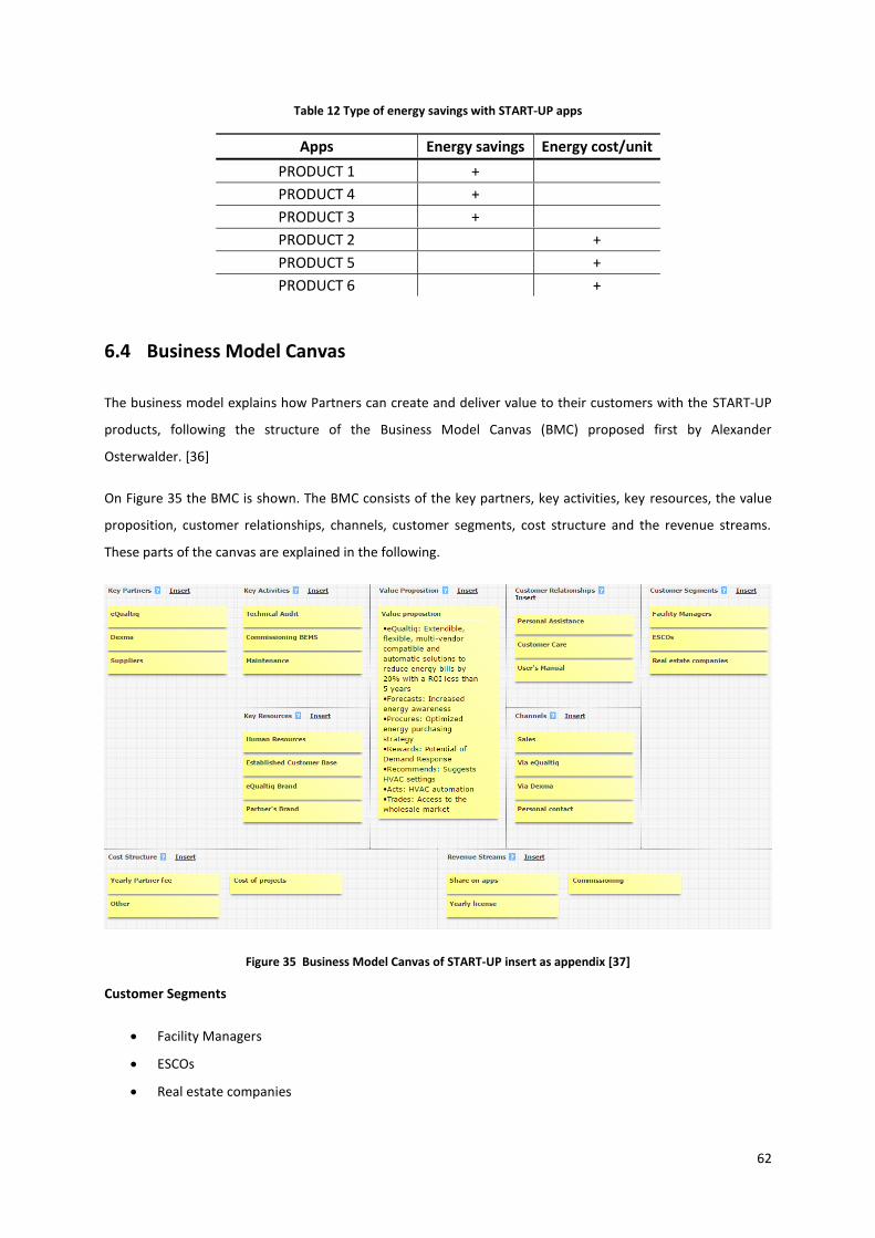
62
Table 12 Type of energy savings with START-UP apps
Apps Energy savings Energy cost/unit
PRODUCT 1 +
PRODUCT 4 +
PRODUCT 3 +
PRODUCT 2 +
PRODUCT 5 +
PRODUCT 6 +
6.4 Business Model Canvas
The business model explains how Partners can create and deliver value to their customers with the START-UP
products, following the structure of the Business Model Canvas (BMC) proposed first by Alexander
Osterwalder. [36]
On Figure 35 the BMC is shown. The BMC consists of the key partners, key activities, key resources, the value
proposition, customer relationships, channels, customer segments, cost structure and the revenue streams.
These parts of the canvas are explained in the following.
Figure 35 Business Model Canvas of START-UP insert as appendix [37]
Customer Segments
Facility Managers
ESCOs
Real estate companies

63
The main customers are the group of people or companies that the Partner aims to reach and serve.
Along with the Value Proposition, owners and operators of facilities over 1000 square meters who want to
reduce energy bills. These customers are facility managers and energy engineers responsible for facilities or
real estate companies owning offices and hotels. Additionally, ESCO companies are potential customers. ESCOs
finance and implement energy efficiency projects on third party buildings and consider energy bill savings as
revenues.
Customer Channels
Sales
Marketing
Via START-UP
Via Dexma
Customer Channels describes the way how the company connects and transfers its Value Proposition to the
Customers.
There are several different ways to communicate the Value Proposition of START-UP products to the Customer.
These channels vary in every company and cannot be defined here. Most of the companies are having a mix of
Customer Channels. Owned Sales is possible through the Sales force and a website, while START-UP and Dexma
provide Partner Sales, by guiding Customers to the Partners.
Customer Relationships
Personal Assistance
Customer Care
User’s Manual
Customer Relationships describes what sort of relationships the company builds with the Customers. These
relationships are driven by the following motivations of customer acquisition, customer retention or the
increase of sales.
Customer Relationships are different in every case. Personal Assistance is supposed to be the most direct way
to reach the Customers. Also, Manuals and Customer Care are available for the products to help Customers
with their daily routine.
Key Resources
Human Resources
Established Customer Base
START-UP Brand
Partner’s Brand

64
Key Resources describes the most important assets necessary for the business model. Without Key Resources
the business model is unable to generate the Value Proposition or Revenues.
Human Resources and the Established Customer Base play an important role as assets. The engineering
experience and knowledge is inevitable for proper commissioning. An Established Customer Base is important
to distribute the new and innovative START-UP products. Also, the use of the START-UP brand increases
confidence in the products.
Key Partnerships
START-UP
Dexma
Suppliers
Key Partnerships contains the group of partners and suppliers that are essential for the business model.
Partnerships are used to optimize the business models, to reduce risks or to acquire resources. The main types
of partnerships defined are strategic alliances, partnership with competitors, joint ventures and buyer-supplier
relations.
Partners have strategic alliance with START-UP and Dexma. Services like helpdesk, trainings, the Dexma
platform and the START-UP apps. Suppliers provide materials or they are sub-contractors in any phase of
commissioning, for example electricians.
Key Activities
Technical Audit
Commissioning BEMS
Maintenance
Key Activities indicates activities that are needed for the business model to work. It is different in every field.
Technical Auditing and Commissioning are field works that are essential to make the START-UP products work.
Also, maintenance is necessary to keep the customer satisfied.
Value Propositions
Generally: Reduced energy bills
PRODUCT 1: Increased energy awareness
PRODUCT 2: Optimized energy purchasing strategy
PRODUCT 5: Potential of Demand Response
PRODUCT 4: Suggests HVAC settings
PRODUCT 3: HVAC automation
PRODUCT 6: Access to the wholesale market

65
Value Propositions are the services and products that create value for the Customers by offering a solution for
a problem or satisfying specific customer needs. These can be recognized or unrecognized customer needs,
customize products to specific needs or offer a better deal in price-sensitive segments.
The value proposition of START-UP products is generally to reduce energy bills. This is done by reducing energy
consumption, buying energy in a lower price, decreasing contracted power or gaining incomes from Demand
Response services with the help of the START-UP apps.
Cost Structure
Yearly Partner fee
Cost of projects
Other
Cost Structure includes all costs in the business model. Costs are usually minimized; however it is less
important in value-driven companies, than in cost-driven ones. The fixed cost of an eQuatiq Partner is the
Yearly Partner fee, which is explained later. Additionally, costs occur in every project. The costs of
commissioning consist of labour costs, material costs and other costs, and these are directly related to the
number and type of projects. Also, the percent after every sold license is calculated as a cost for the licensed
Partner.
Revenue Streams
Share on apps
Commissioning
Maintenance
Revenue streams are the lifeblood of companies. There are one-time customer payments, like the incomes
from commissioning the projects, while recurring revenues are the share from yearly app fees.
6.5 Financial Plan
Revenues
The revenues are the incomes that the customers pay to the company for services and products. There are two
main sources of revenues for the Partner companies. First, an income is due when the START-UP software and
other necessary hardware are commissioned. Secondly, from the yearly fees of the software package installed,
that is in this example is the Platinum package, which price at 10409 €.

66
Table 13 shows the revenues from projects. The values are calculated by adding 20% profit on personnel,
material and other costs.
Table 13 Revenues from commissioning the Platinum package
Revenues for a Platinum project
Platinum licence 10.409 €
Personnel 7.900 €
Material 11.837 €
Other 10.560 €
Total 40.706 €
Costs
Personnel cost, material cost and license cost are directly related to the commissioning of projects for each
customer and it is called direct costs. Direct costs are visible on Table 14 The license cost means the 70% of the
sold licenses that is due to START-UP. The difference between the direct costs and the revenues gives the
operational earnings.
Besides the project related expenditures, the Partner has fixed costs, called overhead costs are visible in Table
15. On top of the yearly Partner fee of 5000 € that provides the right to sell the solutions, the rent of the office,
administration personnel and the cost of a one-time training is included in the overhead costs. The difference
between the operational earnings and the overhead costs gives the value of the gross income (EBIDTA). The
15% taxes are paid after the gross income.
Table 14 Direct costs of a project
Direct cost per project
Personnel 7.182 €
Material 10.761 €
70% of licences 7.286 €
Total 25.229 €
Table 15 Overhead cost of a Partner
Overhead costs
Office 6.000 €
Administration 3.600 €
Partner fee 5.000 €
One time training 5.000 €

67
Cash Flow
It is visible on Table 16 that the sales are forecasted following the stages of product life cycle. The Partner is
assumed to have 5 customers, based on the assumption of Comsa Service, the first potential Partner of START-
UP. In 2017 more than 44000 € profit is expected. Then, until the fourth year a rapid increase in revenues are
expected. This rapid increase in sales is due to the supposed growth stage in the product life cycle. It is clearly
visible, that after 2021 the sales are slowing down, but still more than 300000 € profit is expected.
Table 16 Calculation of cash flow
Cash flow 2017 2018 2019 2020 2021 2022 2023
Revenues
No of projects 5 12 15 18 20 21 22
Income: projects 203.532 € 488.476 € 610.595 € 732.713 € 814.126 € 854.832 € 895.539 €
Income: yearly license - € 5.205 € 17.695 € 33.309 € 52.045 € 72.863 € 94.722 €
Revenues 203.532 € 493.680 € 628.290 € 766.022 € 866.171 € 927.695 € 990.261 €
Direct cost per project
Personnel cost 35.910 € 86.184 € 107.730 € 129.276 € 143.640 € 150.822 € 158.004 €
Material cost 53.805 € 129.132 € 161.415 € 193.698 € 215.220 € 225.981 € 236.742 €
70% of licences 36.432 € 87.436 € 109.295 € 131.153 € 145.726 € 153.012 € 160.299 €
Direct costs 126.147 € 302.752 € 378.440 € 454.127 € 504.586 € 529.815 € 555.045 €
Operational earnings 77.385 € 190.929 € 249.850 € 311.895 € 361.585 € 397.880 € 435.216 €
Overhead costs
Office rental 6.000 € 6.000 € 9.000 € 9.000 € 18.000 € 18.000 € 27.000 €
Administration 9.000 € 16.560 € 19.800 € 23.040 € 25.200 € 26.280 € 27.360 €
One-time training 5.000 € - € - € - € - € - € - €
Yearly Partner fee 5.000 € 5.000 € 5.000 € 5.000 € 5.000 € 5.000 € 5.000 €
Overhead costs 25.000 € 27.560 € 33.800 € 37.040 € 48.200 € 49.280 € 59.360 €
Gross income 52.385 € 163.369 € 216.050 € 274.855 € 313.385 € 348.600 € 375.856 €
Taxes 7.858 € 24.505 € 32.408 € 41.228 € 47.008 € 52.290 € 56.378 €
Profit (net income) 44.527 € 138.863 € 183.643 € 233.627 € 266.377 € 296.310 € 319.478 €

68
Figure 36 shows the cash flow diagram of a Partner. The rapid increase in the first years and the slower
development in the last years are visible.
Figure 36 Cash flow of a Partner’s sales of START-UP products

69

70
7 Conclusions
In this thesis, the energy savings reached and the results of the energy forecasts of a Building Energy
Management System were evaluated. The energy savings were calculated into money and CO2 savings, while
the accuracy of the forecasted energy values was analyzed. The following conclusions were made:
The regression analysis only considers one independent variable, the ambient temperature and
provides an R2=0.78 and R2=0.70 in the baseline and the reporting period respectively. According to
the IPMVP the suggested minimum R2 value is 0.75. It means that ambient temperature is not strictly
correlated to the energy consumption in this building.
The calculated energy saving is 5% compared to the last year’s energy consumption in the summer.
This means 877 € and 2 tCO2 savings. Assuming the same percent for the whole year, the energy
saving is equal to 2090 € and 7 tCO2. However the pay-back time is more than 20 years, it is not an
aspect to take into account at this pilot project.
The energy forecasts provided by the software have an error on the total energy use of 30.4% and
20.3% on hourly basis, 11.9% and 13.3% on a daily basis and 1.8% and 5.0% on a monthly basis. This
means, that the START-UP PRODUCT 1 app needs further testing and development to improve the
outputs and to be a successful product.
The global market for BEMS was worth $3 472 million in 2014 and a 12% of growth is expected
between 2015 and 2020. This means that the development of the product is reasonable and the
potential market is present.
The thesis objectively evaluates the partial results produced by the Building Energy Management System being
developed and provides a suggested business plan for the future distributors of the product. It found, that the
pilot project managed to save 5% energy in the summer (that may be the result of errors) and provide hourly
energy forecasts with an error between 20.3% and 30.4%.

71
72
8 References
[1] European Union, “Statistical Pocketbook 2015,” Publications Office of the European Union, Luxembourg,
2015.
[2] European Environment Agency, “Climate change evident across Europe, confirming urgent need for
adaptation,” 2012. [Online]. Available: http://www.eea.europa.eu/media/newsreleases/climate-change-
evident-across-europe. [Accessed 1 June 2016].
[3] U.S. Global Change Research Program, “Climate Change Imp in the United States, U.S. National Climate
Assessment,” Washington, 2014.
[4] European Commission, “EU-wide headline targets for economic growth,” 2015. [Online]. Available:
http://ec.europa.eu/europe2020/europe-2020-in-a-nutshell/targets/index_en.htm#top. [Accessed 05
April 2016].
[5] European Climate Foundation, “ROADMAP 2050, Technical Analysis,” European Commission, Brussels,
2009.
[6] Intelligent Energy Europe, “Energy Efficiency Trends and Policies in the Household and Tertiary Sectors, An
Analysis Based on the ODYSSEE and MURE Databases,” European Union, Brussels, 2015.
[7] IEA, “Building Energy Performance Metrics, Supporting Energy Efficiency Progress in Major Economies,”
IEA, IPEEC, Paris, 2015.
[8] European Union, “Buildings, European Commission,” 2016. [Online]. Available:
https://ec.europa.eu/energy/en/topics/energy-efficiency/buildings. [Accessed 11 April 2016].
[9] K.O. Aduda, T. Labeodan, W. Zeiler, G. Boxem, Y. Zhao, “Demand side flexibility: Potentials and building
performance implications,” Sustainable Cities and Society, vol. XXII, pp. 146-163, 2016.
[10] Edgar Galván-López, , Tom Curran, , James McDermott, Paula Carroll, “Design of an autonomous intelligent
Demand-Side Management system using stochastic optimisation evolutionary algorithms,”
Neurocomputing, vol. CLXX, p. 270–285, 2015.
[11] Dionysia Kolokotsa, “The role of smart grids in the building sector,” Energy and Buildings, vol. CXVI, p. 703–
708, 2016.

73
[12] Juan Manuel Roldán Fernández, Manuel Burgos Payán, Jesús Manuel Riquelme Santos, Ángel Luis Trigo
García, “Renewable generation versus demand-side management. A comparison for the Spanish market,”
Energy Policy, vol. XCVI, pp. 458-470, 2016.
[13] D. D. Peter Palensky, “Demand Side Management: Demand Response, Intelligent Energy Systems, and
Smart Loads,” IEEE TRANSACTIONS ON INDUSTRIAL INFORMATICS, vol. 7, pp. 381-388, 2011.
[14] M. A. P. Junqiao Han, “Solutions for summer electric power shortages: Demand response and its
applications in air conditioning and refrigerating systems,” Refrigeration, Air Conditioning, & Electric Power
Machinery, vol. 29, pp. 1-4, 2008.
[15] Alessia Arteconi, Eleonora Ciarrocchi, Quanwen Pan, Francesco Carducci, Gabriele Comodi, Fabio Polonara,
Ruzhu Wang, Thermal energy storage coupled with PV panels for demand side management of industrial
building cooling loads, Italy: Elsevier, 2016.
[16] A.Faruqui, D. Harris, R. Hledik, “Unlocking the €53 billion savings from smart meters in the EU: How
increasing the adoption of dynamic tariffs could make or break the EU’s smart grid investment,” 2010.
[17] Claire Bergaentzlé, Cédric Clastres, Haikel Khalfallah, “Demand-side management and European
environmental and energy goals: An optimal complementary approach,” Energy Policy, vol. LXVII, p. 858–
869, 2014.
[18] Office of Energy Efficiency & Renewable Energy, “ISO 50001 ENERGY MANAGEMENT STANDARD,” 2013.
[Online]. Available: http://energy.gov/eere/amo/iso-50001-energy-management-standard. [Accessed 11
June 2016].
[19] International Standardization Organization, “Energy management systems — Requirements with guidance
for use,” 2011. [Online]. Available: https://www.iso.org/obp/ui/#iso:std:iso:50001:ed-1:v1:en. [Accessed
22 July 2016].
[20] P. C. D. D. L. L. Zhenjun Ma, “Existing building retrofits: Methodology and state-of-the-art,” Energy and
Buildings, vol. 55, pp. 889-902, 2012.
[21] Efficiency Valuation Organization, “International Performance Measurement and Verification Protocol,”
Efficiency Valuation Organization , Toronto, 2012.
[22] J. Scott Armstrong, “J. Scott Armstrong,” International Journal of Forecasting, vol. 28, no. 3, pp. 689-694,
2012.
[23] Xin Yan, Xiao Gang Su, Regression Analysis: Theory and Computing, Singapore: World Scientific Publishing

74
Co., 2009.
[24] “DegreeDays,” [Online]. Available: www.degreedays.com.
[25] Claessens Bert, Cot Albert, Duarte Ruth, Gimeo Gemma, Gomez Viriginia, Lodeweyckx Stefan, Orduña
Xavier, Paiz Angel, Perea Eugenio, Polo Merche, Quintana Antoni, “BEEST (Building Energy Efficiency
Management & Smart Grid Integration Tools WP0-F,” KIC InnoEnergy BEEST, Barcelona, 2014.
[26] “Google Maps,” [Online]. Available: www.google.maps.com.
[27] “Wunderground,” [Online]. Available: www.wunderground.com. [Accessed 3 October 2016].
[28] Generalitat de Catalunya, “Estudi comparatiu dels preus de l’energia a Europa,” 2015.
[29] Comsa Emte, [Online]. Available: http://www.comsa.com/. [Accessed 02 June 2016].
[30] Enervalis, [Online]. Available: http://www.enervalis.com/. [Accessed 01 June 2016].
[31] Sauter Controls, [Online]. Available: www.sauter-controls.com. [Accessed 02 June 2016].
[32] B. Ltd., “Global BEMS Market set to approach $7 billion by 2020,” Henry Lawson, December 2014. [Online].
Available: www.bsria.co.uk/news/article/global-bems-market-set-to-approach-7-billion-by-2020/.
[33] BSRIA, “Building Energy Management Systems Opportunities,” 2015.
[34] Building IQ, [Online]. Available: https://buildingiq.com/. [Accessed 11 May 2016].
[35] EnerNOC, [Online]. Available: https://www.enernoc.com/. [Accessed 23 May 2016].
[36] Johnson Electric, [Online]. Available: http://www.johnsonelectric.com/. [Accessed 23 May 2016].
[37] Siemens, “Siemens Building Technologies,” 2016. [Online]. Available:
http://www.buildingtechnologies.siemens.com/. [Accessed 23 May 2016].
[38] Schneider-Electric, [Online]. Available: http://www.schneider-electric.com/. [Accessed 24 May 2016].
[39] Colin J Holcombe, Ebusiness - A complete text, Santiago: Litlangs Publishing Ltda., 2016.
[40] “Canvanizer,” [Online]. Available: www.canvanizer.com.
[41] Infiniti Research Limited, “Global Energy Management Systems Market 2016-2020,” 2016.

75