building a regulated 5v dc power supply
TRANSCRIPT

8/3/2019 Building a Regulated 5V DC Power Supply
http://slidepdf.com/reader/full/building-a-regulated-5v-dc-power-supply 1/3
Building a Regulated 5V DC power supply,
A regulated 5 volt DC supply is essential for powering micro-controller and TTL based circuits.The output of most wall-warts and adapters is to rippled and impure for use in digital circuits.Lets build an inexpensive power supply using some discrete components and a fixed voltage
regulator IC.You will need:
• a step down transformer [12V]
• four silicon diodes [1N4007]
• a resistor [47Ω]
• capacitors [2 x 220µF, 0.3µF and 0.1µF]
• three terminal voltage regulator IC [LM7805]
• a small general propose PCB, some wires, and a suitable output port (I use a
• audio connector).
The circuit of the supply is as given below:
Fig: Circuit Diagram, click to expand.
8/3/2019 Building a Regulated 5V DC Power Supply
http://slidepdf.com/reader/full/building-a-regulated-5v-dc-power-supply 2/3
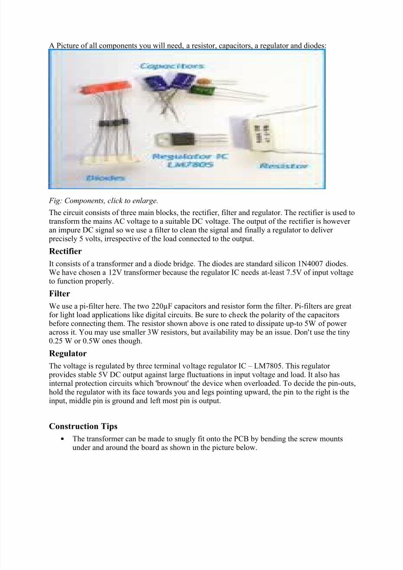
A Picture of all components you will need, a resistor, capacitors, a regulator and diodes:
Fig: Components, click to enlarge.
The circuit consists of three main blocks, the rectifier, filter and regulator. The rectifier is used totransform the mains AC voltage to a suitable DC voltage. The output of the rectifier is however an impure DC signal so we use a filter to clean the signal and finally a regulator to deliver precisely 5 volts, irrespective of the load connected to the output.
Rectifier
It consists of a transformer and a diode bridge. The diodes are standard silicon 1N4007 diodes.We have chosen a 12V transformer because the regulator IC needs at-least 7.5V of input voltageto function properly.
Filter
We use a pi-filter here. The two 220µF capacitors and resistor form the filter. Pi-filters are greatfor light load applications like digital circuits. Be sure to check the polarity of the capacitors before connecting them. The resistor shown above is one rated to dissipate up-to 5W of power across it. You may use smaller 3W resistors, but availability may be an issue. Don't use the tiny0.25 W or 0.5W ones though.
Regulator
The voltage is regulated by three terminal voltage regulator IC – LM7805. This regulator provides stable 5V DC output against large fluctuations in input voltage and load. It also hasinternal protection circuits which 'brownout' the device when overloaded. To decide the pin-outs,hold the regulator with its face towards you and legs pointing upward, the pin to the right is the
input, middle pin is ground and left most pin is output.
Construction Tips
• The transformer can be made to snugly fit onto the PCB by bending the screw mountsunder and around the board as shown in the picture below.

8/3/2019 Building a Regulated 5V DC Power Supply
http://slidepdf.com/reader/full/building-a-regulated-5v-dc-power-supply 3/3
• A 6.3mm or 3.5mm female mono TRS connector (tip, ring, sleeve), also known as an'audio jack' serves as a great output port. The power can then be delivered via standardaudio cables.
• Since the power resistors is quite large, solder it vertically to save space on the board.
• Mount the entire board on thermocol when finished to prevent accidental short circuits.
The finished circuit fits neatly into a 2” by 1.5” PCB, excluding the output jack and plug.You can also include a small switch at the out-put for easy operation. The IC can beheatsink-ed on multiple layers of aluminum foil to dissipate the heat, or if you areenclosing this in a metal box, pin the IC to the sides of the box. This is not entirelynecessary though.
Fig: The finished circuit,