building a home built derby car - scvfascvfa.ca/pdf/home_built_car_instructions.pdfbuilding a home...
TRANSCRIPT

BUILDING A HOME BUILT DERBY CAR
Required Recommended Parts · ComTech 2000 Wheel Set or · Colson 8"x2" Round Tread with 1/2" bore and bearing #AC5-8-565
- AASBD Steering/Brake System
· Steel Axles (Pre-Drilled and Prepped)
· Pulleys, wire for Steering/Brake
Safety Considerations
The overriding requirement in any soapbox race is safety. Mishaps may occur, of course;
but it’s your desire to design and build a car that is safe to drive, and presents
minimal danger to the drivers and spectators. Keep in mind that safety of others is
important and the design of the front( NO METAL) of the racer should be kept from being
too dangerous in a collision. The body of the car should obviously be very sturdy. There
should be some form of bulkhead at the front and back end, securely fastened to the
floorboard, protecting the driver.
Getting Started
Read manual completely.. Begin with a sheet of 3/4" OSB cut in half and glued and
screwed together to form a single 1.5" 2'x8' board. Decide roughly how long and wide
the car is going to be. Points to consider regarding size are:
Size of driver (now and race day).
Transporting it to and from the race.
Moving it in and out of the work area.
Storage after the race.
The body width should be at least 12", and should not exceed the tire to tire width of 32"
specified in the manual earlier. The length is primarily dictated by the height of the
driver. If you sit the driver on the base, and use the starter kit axles, it is possible to get
the basic dimensions established. Also mark the locations of the brake pedal and steering
column. On the stock you are going to use for the floorboard, carefully draw a clear
centerline. You will need this centerline many times during the construction. Mark the
position of axles, brake, brake pedal, seat, tip of the nose, and rear end. With
consideration being given to the type of body you are going to build, the design of the car
and safety. You can outline, perfectly symmetrically around the centerline, the shape of
the floorboard, and cut it. Allow room (at least 6") in front of the feet for a brake pedal
and a post to add weights. Also have in mind the way you wish to finish the front end of
the racer. Solid “bulkheads” are recommended at the very front to protect the driver in
case of an accident and to support the car against the starting block on the starting ramp.
This “bulkhead” should be solidly attached to the floorboard, which is the main structural
element in the racer. Thus, an additional few inches in front of the feet may be required.

At this point, it is also a good idea to determine the shape of the car as seen from above.
Is it going to be an elongated oval, a teardrop shape, or a rectangular box? Again, you
don’t have to make the final decision about the detailed shape, just a general one. Have
the driver sit on the floorboard roughly in the driving position. Prop the child’s back up.
Remember that the feet stick up quite a distance from the floor, and that the eyes of the
driver should be a few inches above the toes so the child can see the road.
Next is to determine the position of the axles for the wheels. Keeping in mind the official
specifications for wheelbase (64"), you should try to distribute the weight of the driver
evenly over the four wheels.
Now think about where the brake/steering column will be placed. Finally you’re ready to
build the body itself. It can be done with plywood, sheet metal, fiberglass or any other
material. This is where you let your imagination roam, and you can come up with new
aerodynamic designs! Always consider your total weight though!
Floorboard Base
The basic body shapes shown here may help you to get your design under way but please
do not feel you are limited by these simple designs:

To create your base cut a 3/4" 4x8' sheet of OSB plywood or stronger down the middle
and glue and screw the two sheets together to form one single 1.5" x 2x8' base. Draw
your center lines and determine and mark your shape. Cut the base shape as desired.
Next, mark the base as previously described for placement of the driver, axles, seatback,
steering column, brake pedal, steering angle limiting blocks and weight rods (for and aft).
Wheels and Axles
The provided wheels must attach to the provided 1/2” axle rod using heavy duty
cotter/hitch pins.
Since the rod isn’t strong enough by itself, a 2x4 piece of yellow pine or stronger to
support the axle
is mandatory. The axle rod must set recessed in a slightly shallower depth (7/16") routed
groove under
the center of the 2x8 support. Steel plates can then be attached on either side to hold the
axle in place as well as a center set screw to keep the axle from rotating. The 2x8 may be
shaped for aerodynamics as desired, just use caution not to reduce the strength of the
wood by reducing its size. When attaching the wheels use 7/8" washers with a 1/2" core
to separate the wheel from the base and the outer pin.

Wheels and Axles (Continued)
Once you have completed the axle assemblies you are then ready to attach them to the
car. Start by drilling holes for attaching the rear axle with two bolts the same size as your
holes. Use washers and lock nuts above the axle assembly. Space the bolts equidistant
from the edge of the car. Be sure not to place the bolts too close to the edge that it
compromises the integrity of the base. Also, notice the rear safety bulkhead in the photo.
The bulkhead also aids in attaching the sides to the car. BE SURE ALIGNMENT IS
STRAIGHT!
Rear Front
Once finished with the rear then work to attach the front axle. The front axle attaches by
using one centered bolt with washers above and below the axle assembly to provide ease
of turning. Be sure to drill the hole for the center bolt very carefully in the center of the
base and exactly to size to avoid any looseness in steering.
Do not tighten the bolt too much as you will want to allow the steering to move easily.
Notice also in the photo the front bulkhead and the left side steering limiter block. The
limiter blocks are used to limit the angle of steering to no more than a 30' circumference.
The reason is to keep the axle assembly from turning any further in the event of an
accident and to help the driver in avoiding over-steering which can cause rollovers. The
front and rear bulkheads in the above photos were formed with 2x4s cut to shape and
securely attached to the base frame. Remember that the front axle center must set 6" from
the nose. Be sure to allow room from the front bulkhead for steering motion.
AASBD Steering / Brake Mount Assembly
It's now time to attach the steering and brake assembly which came as part of the starter
kit. First, place the steering mount in the proper location for the driver and mark its
location, be sure it is centered on the base. Mark the 6 holes in the mount onto the base.
There are 4 mounting holes, one hole for the steering handle column (forward), and one
hole at the bottom of the brake plunger shaft. Once all the holes are marked drill the
mounting holes with the proper sized bit. Then drill the brake plunger hole (center on the
mount). The brake needs a 1" hole to clear the brake plunger. DO NOT DRILL THE
HOLE FOR THE STEERING HANDLE COLUMN YET.

The Steering Handle Column which sets in front of the brake plunger on the Steering
Mount sets down in a shallow hole, this hole DOES NOT go all the way through the
vehicle base but is only about 3/8" deep so that the Steering Handle has a place to set
down into. The width of the hole is about 1" and a quarter (or slug) sets in the hole to be
used as a base for the Steering Handle. Be sure to put the quarter
in the hole before you secure the mount. It is now time to secure the Mount to the Base of
the car. First, bolt on one of the pulley wheels you received in your starter kit to the
mount side. Be sure your bolt
does not interfere with the pulley movement and that you use a lock nut and washer on
the opposite side of the Mount.
Use (2) 1/4" x 2" Elevator Bolts (front). Use (2) 1/4" x 2-1/4" Elev. Bolts (rear). Fasten
each using:
1/4" Flat Washer
1/4" Lock Washer
1/4" Nut

Now, attach the Mount to the Base with elevator bolts from the bottom of the Base and
through the Mount holes. Secure two more Pulleys towards the rear with the 2-1/4" bolts.
Use a washer, then lock washer, then nut for each. Your Steering/Brake Mount should
now be attached to the Base.
Next set the Steering Column down into the front set of holes. It should rest on the
quarter placed in the hole earlier. Lift the column up slightly and
slide a 3/4" (inner dimension) washer up the column and insert a cotter pin
to hold the steering column in place and prevent it from being removed. Bend the cotter
pin around the steering shaft.

Steering Cabling Installation
Parts Needed:
(2) 1/4" x 2-1/4" Elevator Bolts
(2) 1/4" Lock Washers
(2) 1/4" Nuts
(2) 1/4" x 1-1/4" Fender Washer
(2) Included Pulleys
Drill two 1/4" holes placed 6" to the rear of the Steering Mount and 2" from the Base
edge (above). Insert elevator bolts from beneath. Place the fender washer onto bolt, then
Pulley, lock washer, then nut. Tighten.
Its now time to run the steering cable. Start by bending a 10' length of cable in half and
threading it through small hole at the base of the Steering Column (see diagram below).

The cable next passes to the rear Mount pulleys, just setting in the groove of the pulley,
and then onto the pulley on the opposite side of the car, where the wire is wrapped around
the pulley and on to the front steering axles. There are several ways to attach the cable to
the front steering axle, but the safest is to drill a hole forward of the steel axle and insert a
metal grommet for the wire to pass through. The wire can then be clamped to itself with
3/32" cable clamps. Use at least two for safety. You may also install a cable turnbuckle to
tighten the wire (there are many ways to do this). Below is a photo of the AASBD install
design.
The nice thing about this design is that the cable
remains intact and uncut at the turnbuckle which provides much greater security against
clamp failure. If you use this design install one on both sides of the car just behind the
Steering Mount before the wire reaches the rear pulleys.
Brake Installation - Pedal & Plunger
First create a sturdy brake pedal and attach it to the Base with a strong hinge. Bolt the
hinge through the Base using approximately 2" elevator bolts. Do NOT use screws.
Drill a 1/4" hole in the top left and insert a 1/4" x 2-1/4" eyebolt. Use 1/4" nuts and
washers on both sides to hold the eyebolt in place.
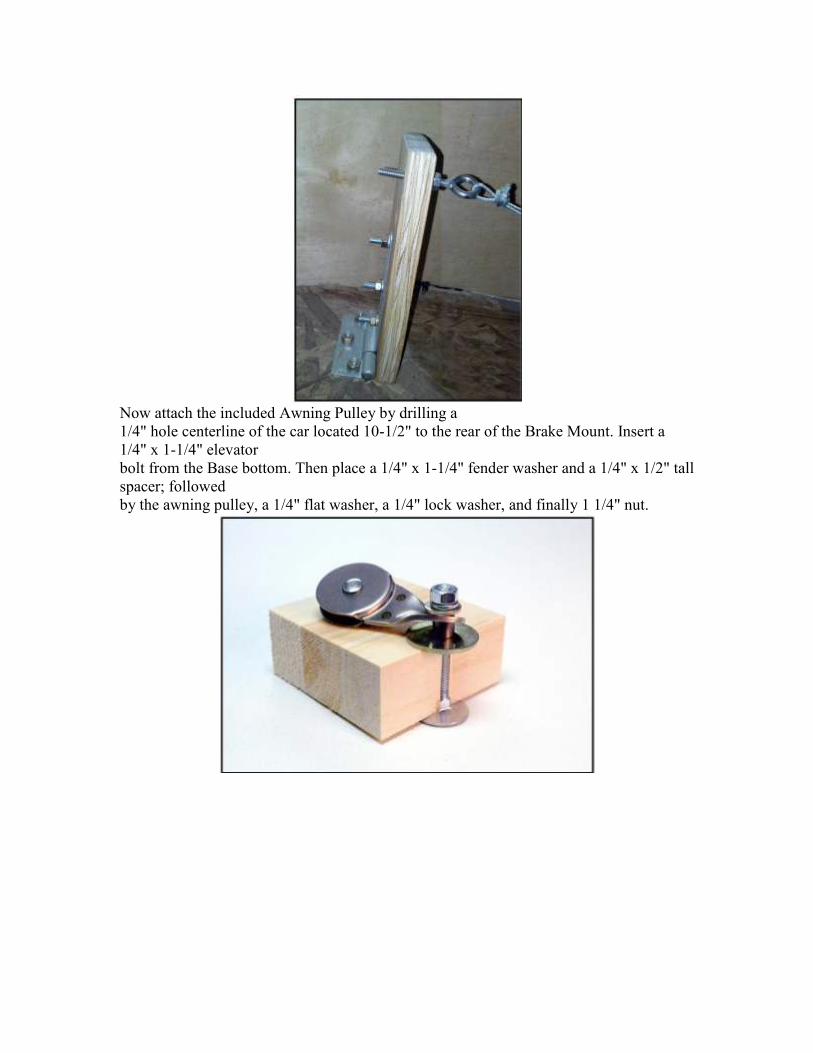
Now attach the included Awning Pulley by drilling a
1/4" hole centerline of the car located 10-1/2" to the rear of the Brake Mount. Insert a
1/4" x 1-1/4" elevator
bolt from the Base bottom. Then place a 1/4" x 1-1/4" fender washer and a 1/4" x 1/2" tall
spacer; followed
by the awning pulley, a 1/4" flat washer, a 1/4" lock washer, and finally 1 1/4" nut.

Next, attach the brake pad with the included hardware to the bottom of the brake plunger.
It is recommended that approximately an eighth of the 1/4" flat head bolt (or three
threads) is exposed.
Insert the brake plunger from the bottom of the car, up
through the Brake Mount installed earlier. Be sure holes at the
top of the Plunger are facing front to back. Set the included Spring onto the Plunger. Push
the Spring down onto the Plunger and install a 1/4" x 2-1/4" eyebolt facing the rear of the
car on the top of the plunger.
Use a lock washer and 1/4" nut to tighten the eyebolt.

Brake Installation - Cable
Next, install the brake cable. Attach approximately 5' of 3/32" cable (included in your
starter kit) to the brake pedal eyebolt with two cable clamps. Run the cable through the
awning pulley (which should now be located about 10 inches to the rear of the Steering
Mount), hen under the pulley on the side of the Steering Mount, finally ending at the
eyebolt on the brake plunger. Be sure the cable is taught and
use two cable clamps on this end of the cable as well.
Your car is now substantially complete and is ready to be tested for steering and braking.
Place the car on a gentle slope or have it pushed while the driver is behind the wheel.
Have the driver check steering and braking. Brakes should respond to quickly stop the
car. Check the wheel alignment (front to back) and be sure the rear axle assembly is
square. Make any adjustments needed now while all parts are easily accessible (before
the body is constructed). Now is a good time to add a seatback as well.

Body Construction - Material Ideas
There are many ways to construct the body of your derby car. One of the easier woods to
work with for its flexibility and ease of use is Luan. Luan will bend to form nice curves
and can easily be mounted to the Base with screws. The demonstration car was
constructed in this manner, and the following build plans are based on this type of wood.
Please feel free to work with other build materials, but always keep in mind the total
weight of the car with the driver must not exceed your weight class.
.
Body Construction - Sides
If you have designed a simply shaped body it will be easy to measure the sides to get the
total length of Luan needed. Also determine the height of the car based on your driver
and their ability to flex for ward during the race to cut wind drag. Once you know your
dimensions then cut two equal pieces of Luan to form the sides. You should also cut two
pieces of bulkhead (2x4s, etc) to be at the front and rear of the car to add sturdiness to the
nose and frame, allow a place for the sides to meet and attach, and add rigidness to the
nose for being placed on the starting ramp. In the photo below you can see how the front
has been reinforced with a steel nose backed by a piece of 2x4 cut to

shape
Body Construction - Top
Once you have attached your sides it's time to consider the top, including the cockpit
access. On the previous page you can see in the photo that PVC piping was used around
the top edge. The PVC is easy to bend to the correct shape and holds screws very well.
Be sure to use proper length screws so the point does not come through to the interior
which could be a hazard to the driver. Also, 1x2" cross braces should also be used to give
strength to the edges of the cockpit top.
Next, cut a length of Luan to the proper width and lay it on top of the car. Mark your
edges and then cut your shape 1/4" inside your mark. This should allow the top to tightly
set inside the sidewalls. Once cut, set your newly cut piece onto the top of the car and
then sand the edges where needed to get a tight fit.
Next, cut out your cockpit entrance based on your drivers size. You may wish to consider
how you can build a sturdier cockpit entrance as Luan is easy to crack when weight is put
on it, such as when the driver gets in and out of the car. One idea would be to make sure
your cross braces (mentioned before) are placed at the rear and front edge of your cockpit
to create a frame which moves the weight to the sides and the base.

Attach the top to the PVC piping so that it lays flush with the sides. Be careful not to
tighten the screws too much or they may pull the top down too much or go through the
Luan. Drilling pilot holes and counter sinking the screws will provide a better finished
look. Apply wood putty over screws, sand and paint your car.
Next you will want to attach the required padding to the edge of the cockpit entrance.
Pipe insulation is a good choice as it will usually come with sticky tape on its edge ready
to attach to the vehicle.
Remember. Be Creative. Have fun!
PREPARING FOR RACE DAY
It is essential that you test the car carefully. Start on a flat driveway and give the car a
healthy push, testing all systems. Ask your driver to execute steering manoeuvres and
also push hard on the brake. Your driver must be able to stop in a designated distance.
Practice days on a small hill will help the driver with the higher speeds of the main hill.
RACE DAY
Race day will be here before you know it. Plan ahead on a way to transport your race car
to the hill(pickup truck, trailer, van). Also, here is a list of some things you may want to
bring with you:
Car Platform: workmate, plastic totes, step ladders, etc
Car Dolly: a device to pull your car from the pits to the starting gate.
Tools: wrenches, pliers, screw drivers, etc
Spare Parts: brake pads, hitch pins, cotter pins, nuts, bolts, weights.
Helmet: You can't race without one!
Misc: chairs, water, snacks, sunscreen, etc.
SAFETY AND SPECIFICATION CHECKLIST
The term “Major Component” refers to the following:
Steering system (Steering wheel, cable, pulleys, connectors etc.) Braking system (Foot
pedal, cable, pulleys, connectors, pads etc.) Suspension system (wheels, axles, axle
supports etc.)
STRUCTURAL SAFETY
All steering and brake system turnbuckles must be prevented from turning due to
vibration.
All “Major Components” must be mounted securely with through bolts, lock washers
and nuts, no nails
All steering and brake system cables must remain snug throughout movement
extremes.
All steering and brake system cables must be terminated with double crimps/clamps.
All parts of the “Major Components” must be accessible for visual inspection.
Wheels must be secured via hitch pins, cotter pins, or other secure method.
Wheels must not bind or rub anywhere throughout movement extremes.
Axles must be securely fastened.
No sharp objects are to be in the vicinity of the driver when seated.
Car must be reasonably solid in construction and free of loose parts.
AASBD steering/brake system is recommended
Steering/brake cable must be 3/32" aircraft cable
Wheels in starter kit must be unaltered. Painting of wheels allowed.
Steering stops must be adequately positioned to limit steering. 1” radius
Car must not exceed weight limit for your selected weight class.