buderus ssb boiler control system manual · the burner and control must be correctly installed and...
TRANSCRIPT

Installation and Service Instructions for Contractors
6720
8929
84 (2
019/0
2) U
SWARNING:Improper installation, set-up, modification, operation or maintenance of the heating system can cause personal injury and property damage.Follow these instructions precisely.If you require assistance or further information, contact a trained and certified installer.
WARNING:The operating instructions are part of the technical documents that must be handed over to the owner or operator of the heating system.Explain to the owner or operator how to use the heating system using the operating instructions. Make sure that they are familiar with all required information for the safe and proper operation of the heating system.
These instructions are available in English and French.
Please keep these instructions for future reference.
BUDERUS SSB BOILER
CONTROL SYSTEM MANUALSSB800 SA | SSB1000 SA | SSB1000 TL
6720892984 (2019/02) US SSB
2 |
1 Key to symbols and safety instructions . . . . . . . . . . . . . . 41.1 Key to symbols . . . . . . . . . . . . . . . . . . . . . . . . . . . . . . . . . .41.2 Safety instructions . . . . . . . . . . . . . . . . . . . . . . . . . . . . . . .41.3 General warning . . . . . . . . . . . . . . . . . . . . . . . . . . . . . . . . .4
2 STAND-ALONE BOILER (Burners Cascade) - SYSTEM ARCHITECTURE . . . . . . . . . . . . . . . . . . . . . . . . . . . . . 62.1 General. . . . . . . . . . . . . . . . . . . . . . . . . . . . . . . . . . . . . . . .62.2 905TS Control Systemn . . . . . . . . . . . . . . . . . . . . . . . . . . .62.2.1 Modbus connection 905PB and 905TS . . . . . . . . . . . . . . .62.2.2 Setpoints on touch screen . . . . . . . . . . . . . . . . . . . . . . . . .72.3 2 Burners Cascade with Touchscreen and Building
Management System (BMS) . . . . . . . . . . . . . . . . . . . . . . .72.4 Dipswitch setting for 2 Burners Cascade . . . . . . . . . . . . . .82.5 Additional device specifications . . . . . . . . . . . . . . . . . . . . .8
3 BURNERS cascade . . . . . . . . . . . . . . . . . . . . . . . . . . . 93.1 Burner cascade communication setup . . . . . . . . . . . . . . . .93.2 Setting the burner address (Rev. 4.0.905.15250). . . . . . . .93.2.1 E2prom address selection through e2prom setting . . . . . .93.2.2 E2prom address selection through dip-switch input. . . . . .93.2.3 Communication with LabVision PC software . . . . . . . . . .103.3 Cascade – Heating only (Rev. 4.0.905.15250). . . . . . . . .103.3.1 Cascade – domestic hot water . . . . . . . . . . . . . . . . . . . . .123.3.2 Cascade – DHW priority (Rev. 3.0.0.12377) . . . . . . . . . .123.3.3 Limitation of the MAX power for DHW (Rev.
4.0.905.16570) . . . . . . . . . . . . . . . . . . . . . . . . . . . . . . . . .123.3.4 Cascade – start/stop sequence (Rev. 3.0.0.12315) . . . . .133.3.5 Cascade – power balance mode (Rev. 4.0.905.15906) . .153.3.6 Cascade – burner rotation (Rev. 4.0.905.x) . . . . . . . . . . .173.3.7 Cascade – error handling . . . . . . . . . . . . . . . . . . . . . . . . .17
4 Service display . . . . . . . . . . . . . . . . . . . . . . . . . . . . .184.1 General. . . . . . . . . . . . . . . . . . . . . . . . . . . . . . . . . . . . . . .184.1.1 Introduction. . . . . . . . . . . . . . . . . . . . . . . . . . . . . . . . . . . .184.1.2 General information . . . . . . . . . . . . . . . . . . . . . . . . . . . . .184.1.3 Display functions . . . . . . . . . . . . . . . . . . . . . . . . . . . . . . .184.1.4 Display icons . . . . . . . . . . . . . . . . . . . . . . . . . . . . . . . . . .184.2 Screens . . . . . . . . . . . . . . . . . . . . . . . . . . . . . . . . . . . . . .194.2.1 Splash screen (Rev 1.1.0.13425). . . . . . . . . . . . . . . . . . .194.2.2 Entering the menu . . . . . . . . . . . . . . . . . . . . . . . . . . . . . .194.2.3 Protected menu items . . . . . . . . . . . . . . . . . . . . . . . . . . .194.2.4 DAir Sequence . . . . . . . . . . . . . . . . . . . . . . . . . . . . . . . . .204.2.5 Language settings . . . . . . . . . . . . . . . . . . . . . . . . . . . . . .204.3 Menu Structure. . . . . . . . . . . . . . . . . . . . . . . . . . . . . . . . .22
5 Main control . . . . . . . . . . . . . . . . . . . . . . . . . . . . . . .265.1 Ignition cycle (Rev 3.0.0.0). . . . . . . . . . . . . . . . . . . . . . . .265.2 Control functions . . . . . . . . . . . . . . . . . . . . . . . . . . . . . . .265.2.1 Demand for central heating (Rev 3.0.0.0) . . . . . . . . . . . .265.2.2 Demand for Domestic Hot Water (Rev 3.0.0.0) . . . . . . . .31
5.3 Safety and system function . . . . . . . . . . . . . . . . . . . . . . .345.3.1 Flame detection (Rev 3.0.0.0) . . . . . . . . . . . . . . . . . . . . .345.3.2 Ionization jumper (Rev 3.0.0.0) . . . . . . . . . . . . . . . . . . . .345.3.3 Flame recovery (Rev 3.0.0.0). . . . . . . . . . . . . . . . . . . . . .345.3.4 Overheat detection (safety limit) (Rev 3.0.0.0). . . . . . . . .345.3.5 Sensor availability (Rev 3.0.0.0). . . . . . . . . . . . . . . . . . . .345.3.6 Pump start every 24 hours (Rev 3.0.0.0) . . . . . . . . . . . . .355.3.7 Frost protection (Rev 3.0.0.0). . . . . . . . . . . . . . . . . . . . . .355.3.8 Flue temperature protection (Rev 3.0.0.0) . . . . . . . . . . . .365.3.9 Input configuration 900MN (Rev 4.0.905.16712) . . . . . . .365.3.10 Output configuration 900MN (Rev 4.0.905.16712) . . . . .365.3.11 Heat exchanger protection: max differential (Rev 3.0.0.0) 375.3.12 Appliance selection (Rev 3.0.0.0). . . . . . . . . . . . . . . . . . .375.3.13 Anti-legionella protection (Rev 3.0.0.0) . . . . . . . . . . . . . .375.3.14 De-Air sequence (Rev 3.0.0.0). . . . . . . . . . . . . . . . . . . . .385.3.15 Low water cut off (Rev 3.0.0.0). . . . . . . . . . . . . . . . . . . . .395.3.16 Heat exchanger protection (Rev 3.0.0.0) . . . . . . . . . . . . .39
6 Boiler cascade . . . . . . . . . . . . . . . . . . . . . . . . . . . . . .416.1 Extended 4x2 boiler/burner cascade with Touch Screen
and Building Management System (BMS) . . . . . . . . . . . .416.2 Compensation for secondary manifold temperature on
single boiler . . . . . . . . . . . . . . . . . . . . . . . . . . . . . . . . . . .426.3 Set Switches for all cascade boards . . . . . . . . . . . . . . . .426.3.1 Power off all the boards . . . . . . . . . . . . . . . . . . . . . . . . . .426.3.2 Set AL Power switch S1 and Dip switch for 905MN
Managing of Boiler X . . . . . . . . . . . . . . . . . . . . . . . . . . . .426.3.3 Set AL Power switch S1 and Dip switch for 905MN
Dependent boards . . . . . . . . . . . . . . . . . . . . . . . . . . . . . .426.4 Set the Modules and Boiler Cascade Settings . . . . . . . .426.4.1 Cascade of Modules: Set the address for all the
modules Boards . . . . . . . . . . . . . . . . . . . . . . . . . . . . . . .426.4.2 Cascade of Modules: Set Number of expected Modules
(to do only in the managing of Modules) . . . . . . . . . . . . .426.4.3 Cascade of Boilers: Set Boiler Address for all the
Managing boards . . . . . . . . . . . . . . . . . . . . . . . . . . . . . . .426.4.4 Cascade of Boilers: Set Number of expected Boiler (to
do only in the managing of Boiler) . . . . . . . . . . . . . . . . . .42
7 System test . . . . . . . . . . . . . . . . . . . . . . . . . . . . . . . .437.1 System test (Rev 3.0.0.0). . . . . . . . . . . . . . . . . . . . . . . . .437.1.1 System test for cascade burners with air-damper
functionality . . . . . . . . . . . . . . . . . . . . . . . . . . . . . . . . . . .437.2 Physical high limit test mode. (100°C +/- 5°C). . . . . . . . .437.2.1 Starting the test . . . . . . . . . . . . . . . . . . . . . . . . . . . . . . . .437.2.2 Running the test . . . . . . . . . . . . . . . . . . . . . . . . . . . . . . . .437.2.3 Stopping the test . . . . . . . . . . . . . . . . . . . . . . . . . . . . . . .447.2.4 Monitoring of attempts . . . . . . . . . . . . . . . . . . . . . . . . . . .447.2.5 Limitations . . . . . . . . . . . . . . . . . . . . . . . . . . . . . . . . . . . .447.3 LWCO Error evaluated at Boiler level. . . . . . . . . . . . . . . .447.4 System test in cascades with air damper . . . . . . . . . . . .44
8 Service reminder . . . . . . . . . . . . . . . . . . . . . . . . . . . .458.1 Service Reminder. . . . . . . . . . . . . . . . . . . . . . . . . . . . . . .45
Contents
SSB 6720892984 (2019/02) US
| 3
8.1.1 Service Reminder. . . . . . . . . . . . . . . . . . . . . . . . . . . . . . .458.1.2 Service Overdue logging . . . . . . . . . . . . . . . . . . . . . . . . .458.1.3 Service Reminder implementations . . . . . . . . . . . . . . . . .458.1.4 Resetting the Service Reminder. . . . . . . . . . . . . . . . . . . .458.1.5 Menu’s and Parameters . . . . . . . . . . . . . . . . . . . . . . . . . .45
Appendix A - Connection diagram . . . . . . . . . . . . . . . . . . . .46
Appendix B - Maximum load on outputs . . . . . . . . . . . . . . . . .48
Appendix C - System parameters . . . . . . . . . . . . . . . . . . . . .49
Appendix D - Control System Technical Specifications . . . . . . .54
Appendix E - NTC sensor curve selection (Rev 3 .0 .0 .0) . . . . . . .55
Appendix F - 5 Error table (Rev . 4 .0 .905 .17114) . . . . . . . . . . . . .55
Appendix G - PID: Proportional-Integral-Derivative controller . . .59
Appendix H - Cascade parameter . . . . . . . . . . . . . . . . . . . . .62
Appendix I - Connector description for 905mn1x (120vac version) 63
Appendix J - PB Connectors Description . . . . . . . . . . . . . . . .65
Appendix K - Modbus . . . . . . . . . . . . . . . . . . . . . . . . . . . .67
Appendix L - Safety timing . . . . . . . . . . . . . . . . . . . . . . . . .73
Appendix M - Building Management System (BMS) Registers Specifications . . . . . . . . . . . . . . . . . . . . . . . . . . . . . .75
6720892984 (2019/02) US SSB
4 | Key to symbols and safety instructions
1 Key to symbols and safety instructions
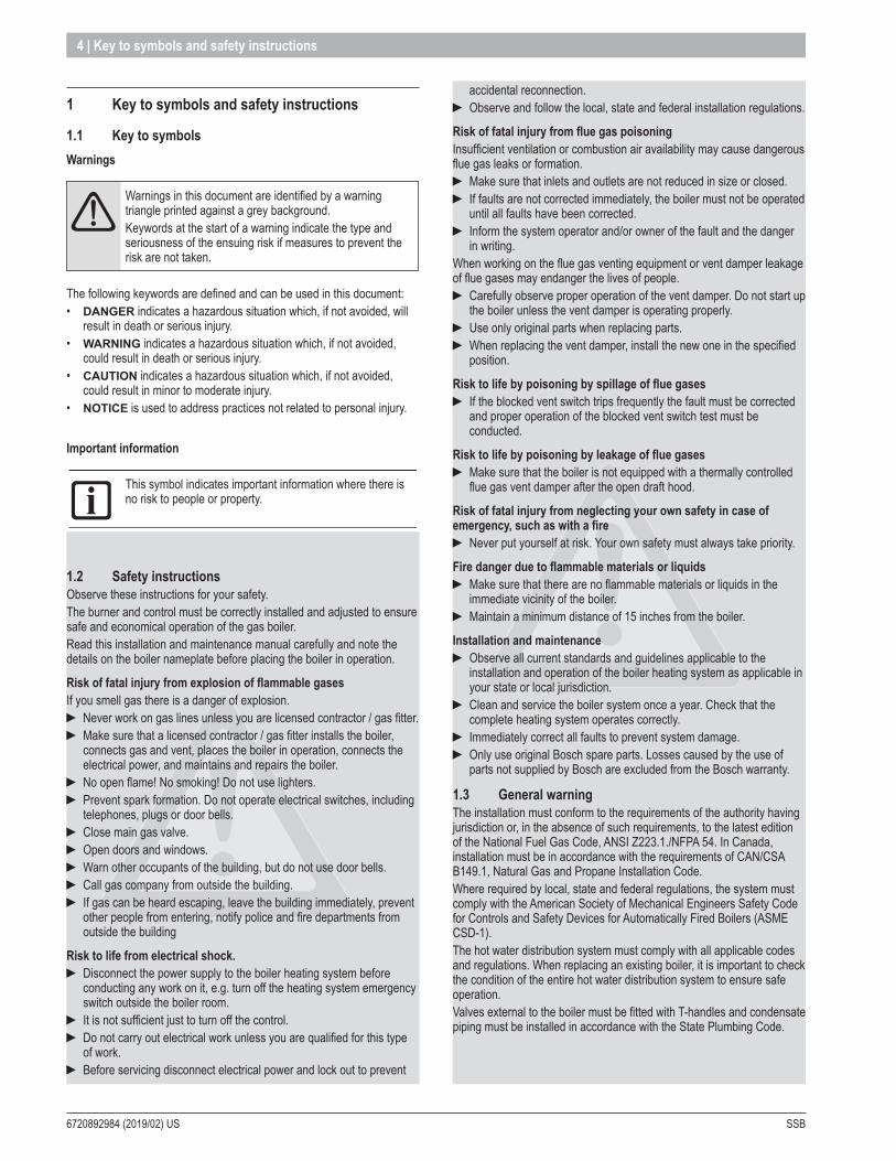
1 .1 Key to symbolsWarnings
aaWarnings in this document are identified by a warning triangle printed against a grey background.Keywords at the start of a warning indicate the type and seriousness of the ensuing risk if measures to prevent the risk are not taken.
The following keywords are defined and can be used in this document:• DANGER indicates a hazardous situation which, if not avoided, will
result in death or serious injury.• WARNING indicates a hazardous situation which, if not avoided,
could result in death or serious injury.• CAUTION indicates a hazardous situation which, if not avoided,
could result in minor to moderate injury.• NOTICE is used to address practices not related to personal injury.
Important information
amThis symbol indicates important information where there is no risk to people or property.
1 .2 Safety instructionsObserve these instructions for your safety.The burner and control must be correctly installed and adjusted to ensure safe and economical operation of the gas boiler.Read this installation and maintenance manual carefully and note the details on the boiler nameplate before placing the boiler in operation.
Risk of fatal injury from explosion of flammable gasesIf you smell gas there is a danger of explosion.
► Never work on gas lines unless you are licensed contractor / gas fitter. ► Make sure that a licensed contractor / gas fitter installs the boiler, connects gas and vent, places the boiler in operation, connects the electrical power, and maintains and repairs the boiler.
► No open flame! No smoking! Do not use lighters. ► Prevent spark formation. Do not operate electrical switches, including telephones, plugs or door bells.
► Close main gas valve. ► Open doors and windows. ► Warn other occupants of the building, but do not use door bells. ► Call gas company from outside the building. ► If gas can be heard escaping, leave the building immediately, prevent other people from entering, notify police and fire departments from outside the building
Risk to life from electrical shock . ► Disconnect the power supply to the boiler heating system before conducting any work on it, e.g. turn off the heating system emergency switch outside the boiler room.
► It is not sufficient just to turn off the control. ► Do not carry out electrical work unless you are qualified for this type of work.
► Before servicing disconnect electrical power and lock out to prevent
accidental reconnection. ► Observe and follow the local, state and federal installation regulations.
Risk of fatal injury from flue gas poisoningInsufficient ventilation or combustion air availability may cause dangerous flue gas leaks or formation.
► Make sure that inlets and outlets are not reduced in size or closed. ► If faults are not corrected immediately, the boiler must not be operated until all faults have been corrected.
► Inform the system operator and/or owner of the fault and the danger in writing.
When working on the flue gas venting equipment or vent damper leakage of flue gases may endanger the lives of people.
► Carefully observe proper operation of the vent damper. Do not start up the boiler unless the vent damper is operating properly.
► Use only original parts when replacing parts. ► When replacing the vent damper, install the new one in the specified position.
Risk to life by poisoning by spillage of flue gases ► If the blocked vent switch trips frequently the fault must be corrected and proper operation of the blocked vent switch test must be conducted.
Risk to life by poisoning by leakage of flue gases ► Make sure that the boiler is not equipped with a thermally controlled flue gas vent damper after the open draft hood.
Risk of fatal injury from neglecting your own safety in case of emergency, such as with a fire
► Never put yourself at risk. Your own safety must always take priority.
Fire danger due to flammable materials or liquids ► Make sure that there are no flammable materials or liquids in the immediate vicinity of the boiler.
► Maintain a minimum distance of 15 inches from the boiler.
Installation and maintenance ► Observe all current standards and guidelines applicable to the installation and operation of the boiler heating system as applicable in your state or local jurisdiction.
► Clean and service the boiler system once a year. Check that the complete heating system operates correctly.
► Immediately correct all faults to prevent system damage. ► Only use original Bosch spare parts. Losses caused by the use of parts not supplied by Bosch are excluded from the Bosch warranty.
1 .3 General warningThe installation must conform to the requirements of the authority having jurisdiction or, in the absence of such requirements, to the latest edition of the National Fuel Gas Code, ANSI Z223.1./NFPA 54. In Canada, installation must be in accordance with the requirements of CAN/CSA B149.1, Natural Gas and Propane Installation Code.Where required by local, state and federal regulations, the system must comply with the American Society of Mechanical Engineers Safety Code for Controls and Safety Devices for Automatically Fired Boilers (ASME CSD-1).The hot water distribution system must comply with all applicable codes and regulations. When replacing an existing boiler, it is important to check the condition of the entire hot water distribution system to ensure safe operation.Valves external to the boiler must be fitted with T-handles and condensate piping must be installed in accordance with the State Plumbing Code.
SSB 6720892984 (2019/02) US
Key to symbols and safety instructions | 5
NOTICE: ► This boiler must be installed by a licensed contractor/ gas fitter. Failure to do so shall void the product warranty.
► The boiler is intended only for the use for which it was specifically designed and built. Bosch is hereby excluded from any liability for damages caused to persons, animals or property resulting from installation errors, improper adjustment, maintenance or use.
► In order to ensure safety and correct operation, the installation shall always take place in full compliance with the applicable codes and following with the instructions provided by the manufacturer, and must always be carried out by a licensed contractor / gas fitter only.
► The equipment must be installed in appropriate place and in combination with appropriate systems as specified by code.
► The unit may be exposed to temperatures between 5 deg F (-15°C) and 150 deg F (65°C) in its original packaging. Do not expose the unit to weather without the protection of the original packaging until the boiler has been properly installed. Until then there is no frost protection for the boiler.
► After removing the packaging check the integrity and completeness of delivery and in case of non-compliance, contact your dealer.
► If there is a water loss, disconnect the boiler from the main power supply, close the water supply and immediately call technical assistance or installer/local contractor.
► Periodically check that the condensate drain is free from obstruction. ► Periodically check the system pressure. System pressure should be checked when the system is in standby mode and no call for heat is present.
► Maintenance is mandatory and shall be carried out at least once a year.
► This manual shall be read carefully, in order to install and operate the boiler appropriately, and safely.
► Boiler installations, settings and service should only be performed by experienced licensed contractor / gas fitter. End Users should only make adjustments with the assistance of a licensed contractor / gas fitter.
► Any maintenance operation or service before disconnecting the boiler from the main power supply is forbidden.
► Do not remove or modify safety equipment. ► Do not pull or twist the electrical wires, from the boiler, even if the device is disconnected from the main power supply.
► Do not obstruct or reduce the ventilation openings. ► Do not install the unit outdoors. ► Do not leave any combustibles or containers of flammable substances in the room where the boiler is installed.
► Keep packing material out of reach of children as it can be potentially dangerous. It must be disposed of as required by law.
► The opening of metal casing of the device and removing of the cover are prohibited to the end user. Any service on the boiler must be carried out by authorized personal.
► It’s prohibited to dispose the product as domestic waste. The separate disposal of a household appliance avoids possible negative consequences for the environment and human health deriving from inappropriate disposal and allows to recover the materials it is made of in order to achieve significant savings in energy and resources.
6720892984 (2019/02) US SSB
6 | STAND-ALONE BOILER (Burners Cascade) - SYSTEM ARCHITECTURE
2 STAND-ALONE BOILER (Burners Cascade) - SYSTEM ARCHITECTURE
2 .1 GeneralThe 900 series burner controls are designed to function as a standalone control unit for intermittent operation on heating appliances with a premix (modulating) burner and a pneumatic air-gas system.
This specification is suitable for the following version:
PN: 900MN 900MN type for Commercial units
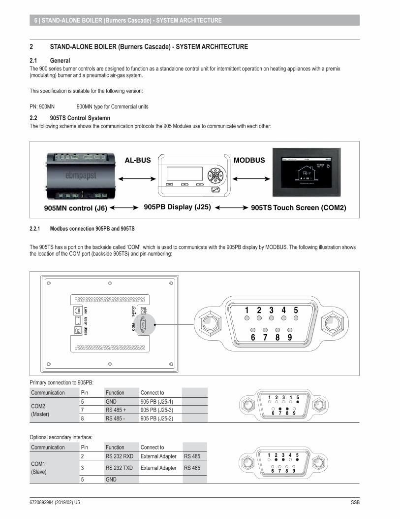
2 .2 905TS Control SystemnThe following scheme shows the communication protocols the 905 Modules use to communicate with each other:
AL-BUS MODBUS
905TS Touch Screen (COM2)905PB Display (J25)905MN control (J6)
2 .2 .1 Modbus connection 905PB and 905TS
The 905TS has a port on the backside called ‘COM’, which is used to communicate with the 905PB display by MODBUS. The following illustration shows the location of the COM port (backside 905TS) and pin-numbering:
6 7 8 9
1 2 3 4 5L
AN
US
B1
US
B2
CO
M24
VD
C +
-
Primary connection to 905PB:Communication Pin Function Connect to
6 7 8 9
1 2 3 4 5
COM2(Master)
5 GND 905 PB (J25-1)7 RS 485 + 905 PB (J25-3)8 RS 485 - 905 PB (J25-2)
Optional secondary interface:Communication Pin Function Connect to
6 7 8 9
1 2 3 4 5
COM1(Slave)
2 RS 232 RXD External Adapter RS 485
3 RS 232 TXD External Adapter RS 485
5 GND
SSB 6720892984 (2019/02) US
STAND-ALONE BOILER (Burners Cascade) - SYSTEM ARCHITECTURE | 7
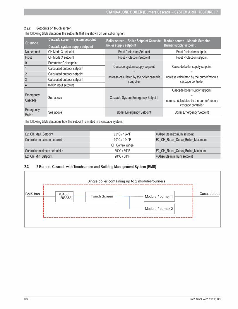
2 .2 .2 Setpoints on touch screenThe following table describes the setpoints that are shown on ver 2.d or higher:
CH modeCascade screen – System setpoint
Cascade system supply setpointBoiler screen – Boiler Setpoint Cascade boiler supply setpoint
Module screen – Module Setpoint Burner supply setpoint
No demand CH Mode X setpoint Frost Protection Setpoint Frost Protection setpointFrost CH Mode X setpoint Frost Protection Setpoint Frost Protection setpoint0 Parameter CH setpoint
Cascade system supply setpoint +
increase calculated by the boiler cascade controller
Cascade boiler supply setpoint +
increase calculated by the burner/module cascade controller
1 Calculated outdoor setpoint2 Calculated outdoor setpoint3 Calculated outdoor setpoint4 0-10V input setpoint
EmergencyCascade See above Cascade System Emergency Setpoint
Cascade boiler supply setpoint +
increase calculated by the burner/module cascade controller
EmergencyBoiler See above Boiler Emergency Setpoint Boiler Emergency Setpoint
The following table describes how the setpoint is limited in a cascade system:
E2_Ch_Max_Setpoint 90°C / 194°F = Absolute maximum setpointController maximum setpoint = 90°C / 194°F E2_CH_Reset_Curve_Boiler_Maximum
CH Control rangeController minimum setpoint = 30°C / 86°F E2_CH_Reset_Curve_Boiler_MinimumE2_Ch_Min_Setpoint 20°C / 68°F = Absolute minimum setpoint
2 .3 2 Burners Cascade with Touchscreen and Building Management System (BMS)
Single boiler containing up to 2 modules/burners
BMS bus Cascade busModule / burner 1Touch ScreenRS485
RS232
Module / burner 2
6720892984 (2019/02) US SSB
8 | STAND-ALONE BOILER (Burners Cascade) - SYSTEM ARCHITECTURE
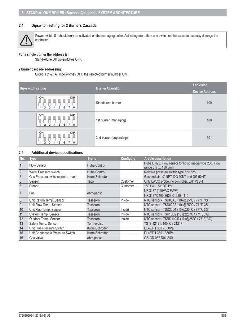
2 .4 Dipswitch setting for 2 Burners Cascade
aaPower switch S1 should only be activated on the managing boiler. Activating more than one switch on the cascade bus may damage the controller!
For a single burner the address is: Stand-Alone: All dip-switches OFF.
2 burner cascade addressing: Group 1 (1-2): All dip-switches OFF, the selected burner number ON.
Dip-switch setting Burner OperationLabVision
Device Address
1
ON DIP
2 3 4 5 6 7 8
1
ON DIP
2 3 4 5 6 7 8
1
ON DIP
2 3 4 5 6 7 8
1
ON DIP
2 3 4 5 6 7 8
1
ON DIP
2 3 4 5 6 7 8
1
ON DIP
2 3 4 5 6 7 8
1
ON DIP
2 3 4 5 6 7 8
1
ON DIP
2 3 4 5 6 7 8
1
ON DIP
2 3 4 5 6 7 8
Standalone burner 1001
ON DIP
2 3 4 5 6 7 8
1
ON DIP
2 3 4 5 6 7 8
1
ON DIP
2 3 4 5 6 7 8
1
ON DIP
2 3 4 5 6 7 8
1
ON DIP
2 3 4 5 6 7 8
1
ON DIP
2 3 4 5 6 7 8
1
ON DIP
2 3 4 5 6 7 8
1
ON DIP
2 3 4 5 6 7 8
1
ON DIP
2 3 4 5 6 7 8
1st burner (managing) 100
1
ON DIP
2 3 4 5 6 7 8
1
ON DIP
2 3 4 5 6 7 8
1
ON DIP
2 3 4 5 6 7 8
1
ON DIP
2 3 4 5 6 7 8
1
ON DIP
2 3 4 5 6 7 8
1
ON DIP
2 3 4 5 6 7 8
1
ON DIP
2 3 4 5 6 7 8
1
ON DIP
2 3 4 5 6 7 8
1
ON DIP
2 3 4 5 6 7 8
2nd burner (depending) 101
2 .5 Additional device specificationsNo . Type Brand Configure Article description
1 Flow Sensor Huba Control Huba DN25. Flow sensor for liquid media type 200. Flow range 0,5 … 150 l/min
2 Water Pressure switch Huba Control Relative pressure switch type 620/6253 Gas Pressure switches (min.–max) Krom Schroder Gas and air, ¼” NPT, DG 50NT and DG 50HT5 Sensor Taco Customer Only LWCO probe, no controller, 3/8” P8S-16 Burner Customer 150 kW ~ 511BTU/hr
7 Fan ebm-papst NRG137 (120VAC PWM)NRG137/2400-3633-010304-115
8 Unit Return Temp. Sensor Tasseron Inside NTC sensor - TSD00AE (10k@25°C / 77°F, 3%)9 Unit Flow Temp. Sensor Tasseron NTC sensor - TSD00AE (10k@25°C / 77°F, 3%)10 Unit Flue Temp. Sensor Tasseron Inside NTC sensor - TSD20D1 (10k@25°C / 77°F, 3%)11 System Temp. Sensor Tasseron Inside NTC sensor - TSK10D2 (10k@25°C / 77°F, 3%)12 Outdoor Temp. Sensor Tasseron Inside NTC sensor - TSRD110-R (10k@25°C / 77°F, 3%)13 Safety Temp. Sensor Term-o-disc TS18-12491, 100°C / 212°F14 Unit Flue Pressure Switch Krom Schroder DL4ET-1 330 - 350Pa15 Unit Condensate Pressure Switch Krom Schroder DL4ET-1 330 - 350Pa16 Gas valve ebm-papst GB-GD 057 D01 S00

SSB 6720892984 (2019/02) US
BURNERS cascade | 9
3 BURNERS cascade
3 .1 Burner cascade communication setupIn order for the system to work for cascade the communication busses must be parallel linked together. The managing burner uses the AL-bus connection on J6 1-8 for burner cascade. The depending burner must be connected to the managing burner on the J8 AL-bus connection.It is important that the power on the J8 AL-bus connection on all depending burners is switched to the OFF position. Also all burners in the cascade system must have a unique address selected.
Demand: 0-10V / OpenTherm / On-Off
T outside
Boiler sensor
J6
J8
90xMN -
90xMN –
––
D2
90xMN D1Boiler manager
3 .2 Setting the burner address (Rev . 4 .0 .905 .15250)The managing burner of the cascade system is connected to the AL-bus connection on J6 1-8. This connection also provides the power for the communication bus. The depending burners are all parallel connected to the managing burner communication bus.Since the bus power is provided by the managing burner on J6 1-8, switch S1 must be set in the OFF position on all controls.
ONOFF
J8J11
The burner address can be set through an e2prom setting or the Dip-Switch input available on the control. Which option is used can be set with the Dip-switch configuration parameter on the Labvision PC software. Each burner must be configured with its own unique address.
3 .2 .1 E2prom address selection through e2prom settingWhen the Dip-switch configuration is set to disabled the burner address is selected with an e2prom parameter. This setting can be changed using a computer with LabVision PC software.
Burner address Burner Operation
Function of sensor input J5 (7-15)
LabVision Device Address
0 (default) Standalone burner No function 100
1 1st boiler (Managing) System sensor 100
2 2nd boiler (dependent) No function 101
3 3rd boiler (dependent) No function 102
4 4th boiler (dependent) No function 103
$ $ $
8 8th boiler (dependent) No function 107
3 .2 .2 E2prom address selection through dip-switch inputWhen the Dip-switch configuration is set to Cascade burner address the burner address is selected with the dip-switch input. The switches are numbered 1 to 8. When an invalid dip-switch setting is selected the burner address will be set to a standalone burner. When the Dip-switch configuration is set to Cascade burner address the E2prom parameter is not used.
Dip-switch setting Burner Operation
LabVision
Device Address
1
ON DIP
2 3 4 5 6 7 8
1
ON DIP
2 3 4 5 6 7 8
1
ON DIP
2 3 4 5 6 7 8
1
ON DIP
2 3 4 5 6 7 8
1
ON DIP
2 3 4 5 6 7 8
1
ON DIP
2 3 4 5 6 7 8
1
ON DIP
2 3 4 5 6 7 8
1
ON DIP
2 3 4 5 6 7 8
1
ON DIP
2 3 4 5 6 7 8
Standalone burner 1001
ON DIP
2 3 4 5 6 7 8
1
ON DIP
2 3 4 5 6 7 8
1
ON DIP
2 3 4 5 6 7 8
1
ON DIP
2 3 4 5 6 7 8
1
ON DIP
2 3 4 5 6 7 8
1
ON DIP
2 3 4 5 6 7 8
1
ON DIP
2 3 4 5 6 7 8
1
ON DIP
2 3 4 5 6 7 8
1
ON DIP
2 3 4 5 6 7 8
1st burner (managing) 100
1
ON DIP
2 3 4 5 6 7 8
1
ON DIP
2 3 4 5 6 7 8
1
ON DIP
2 3 4 5 6 7 8
1
ON DIP
2 3 4 5 6 7 8
1
ON DIP
2 3 4 5 6 7 8
1
ON DIP
2 3 4 5 6 7 8
1
ON DIP
2 3 4 5 6 7 8
1
ON DIP
2 3 4 5 6 7 8
1
ON DIP
2 3 4 5 6 7 8
2nd burner (depending) 101
6720892984 (2019/02) US SSB
10 | BURNERS cascade
3 .2 .3 Communication with LabVision PC softwareThere are two options for communication with the LabVision PC software. The 850US Device (Argus-to-USB) can either be parallel connected to the cascade communication bus or separately to the J8 connection on the leading burner. When the 850US Device (Argus-to-USB) is connected to the J8 connection, switch S1 has to be set in the ON position. This powers the communication bus to allow communication with the Labvision PC software.
NOTE: there is less information available when connected to the J8 connection on the leading burner. Only the information known by the leading burner can be shown in the Labvision PC software.
3 .3 Cascade – Heating only (Rev . 4 .0 .905 .15250)Managing burner When a burner is set as Managing (Address = 1), the controller of this burner will drive the cascade. The CH mode of this managing burner applies to all other burners. It is only required to set the CH mode on the managing burner. • The outdoor temperature sensor connected to the managing burner
will be the outdoor sensor for the cascade operation• The system sensor (T_System) connected to the managing burner
will be the control sensor for the cascade supply temperature.• The (modulating) thermostat connected to the managing burner will
be the CH heat demand input for the cascade system.
Based on the system temperature (T_System) and the requested Cascade_Setpoint the managing burner calculates a required burner setpoint, to achieve the requested Cascade_Setpoint.The managing burner provides the calculated setpoint to all dependent burners. The modulating power of the dependent burners is PID controlled based on the calculated setpoint and dependent burner supply temperature.
Cascade CH setpoint adaption When the system temperature is not high enough the setpoint for all burners will be adjusted. The boiler setpoint will be increased when the system temperature drops below Cascade_Setpoint and decreased when it rises above Cascade_Setpoint temperature.This is determined as following: A PID-control loop over the system temperature (Cascade_Setpoint / T_System) calculates the adjustment of the boiler setpoint. The range of the PID controller is between (Cascade_Setpoint + Max_Range_Up_Limit) and (Cascade_Setpoint – Min_Range_Down_Limit). This offset is added to the Cascade_Setpoint and then this calculated boiler setpoint will be limited at CH_Max_Setpoint (by default 80°C (176°F)).
When the system temperature is above cascade setpoint, the calculated boiler setpoint will be decreased with a step defined by parameter PID_Slew_Rate_Step_Down (default 1°C (1,8°F)).
In case the system temperature is below cascade setpoint the calculated boiler setpoint will be increased with a step defined by parameter PID_Slew_Rate_Step_Up (default 1°C (1,8°F)).
The PID calculation does not start immediately but after a certain delay period to stabilize the system first.
The delay period is Start_PID_Modulation_Delay_Factor (settable), for example 60 minutes.
SSB 6720892984 (2019/02) US
BURNERS cascade | 11
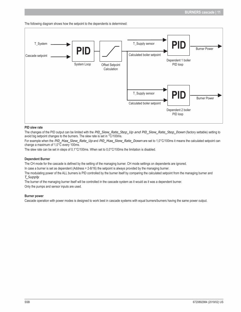
The following diagram shows how the setpoint to the dependents is determined:
T_System
Cascade setpoint
Burner Power
T_Supply sensor
T_Supply sensor PID
PID
System Loop
Burner Power
Offset SetpointCalculation
Calculated boiler setpoint
Calculated boiler setpoint PIDDependent 1 boiler
PID loop
Dependent 2 boilerPID loop
PID slew rateThe changes of the PID output can be limited with the PID_Slew_Rate_Step_Up and PID_Slew_Rate_Step_Down (factory settable) setting to avoid big setpoint changes to the burners. The slew rate is set in °C/100ms. For example when the PID_Max_Slew_Rate_Up and PID_Max_Slew_Rate_Down are set to 1,0°C/100ms it means the calculated setpoint can change a maximum of 1,0°C every 100ms.The slew rate can be set in steps of 0,1°C/100ms. When set to 0,0°C/100ms the limitation is disabled.
Dependent BurnerThe CH mode for the cascade is defined by the setting of the managing burner. CH mode settings on dependents are ignored.In case a burner is set as dependent (Address = 2-8/16) the setpoint is always provided by the managing burner.The modulating power of the ALL burners is PID controlled by the burner itself by comparing the calculated setpoint from the managing burner and T_Supply. The burner of the managing burner itself will be controlled in the cascade system as it would as it was a dependent burner. Only the pumps and sensor inputs are used.
Burner powerCascade operation with power modes is designed to work best in cascade systems with equal burners/burners having the same power output.
6720892984 (2019/02) US SSB
12 | BURNERS cascade
3 .3 .1 Cascade – domestic hot waterSettingsIn the installer DHW menu of the managing burner control the DHW_Mode should be set. Available DHW modes in cascade are mode 1 or 2.
Dependent BurnerIn case a burner is set as dependent (Address = 2-8/16) the DHW setpoint is always provided by the managing burner, the internal control of the setpoint functions are disabled.
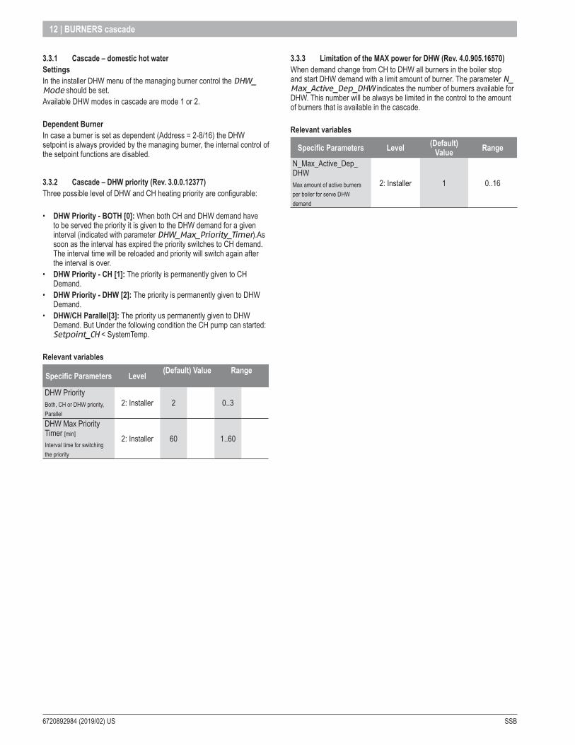
3 .3 .2 Cascade – DHW priority (Rev . 3 .0 .0 .12377)Three possible level of DHW and CH heating priority are configurable:
• DHW Priority - BOTH [0]: When both CH and DHW demand have to be served the priority it is given to the DHW demand for a given interval (indicated with parameter DHW_Max_Priority_Timer).As soon as the interval has expired the priority switches to CH demand. The interval time will be reloaded and priority will switch again after the interval is over.
• DHW Priority - CH [1]: The priority is permanently given to CH Demand.
• DHW Priority - DHW [2]: The priority is permanently given to DHW Demand.
• DHW/CH Parallel[3]: The priority us permanently given to DHW Demand. But Under the following condition the CH pump can started: Setpoint_CH < SystemTemp.
Relevant variables
Specific Parameters Level (Default) Value Range
DHW PriorityBoth, CH or DHW priority, Parallel
2: Installer 2 0..3
DHW Max Priority Timer [min]
Interval time for switching the priority
2: Installer 60 1..60
3 .3 .3 Limitation of the MAX power for DHW (Rev . 4 .0 .905 .16570)When demand change from CH to DHW all burners in the boiler stop and start DHW demand with a limit amount of burner. The parameter N_Max_Active_Dep_DHW indicates the number of burners available for DHW. This number will be always be limited in the control to the amount of burners that is available in the cascade.
Relevant variables
Specific Parameters Level (Default) Value Range
N_Max_Active_Dep_DHWMax amount of active burners per boiler for serve DHW demand
2: Installer 1 0..16

SSB 6720892984 (2019/02) US
BURNERS cascade | 13
3 .3 .4 Cascade – start/stop sequence (Rev. 3.0.0.12315)The managing burner sends the calculated Cascade_Setpoint to the dependent burners. The power of the burners is PID controlled based on the Calculated_Setpoint and T_Supply. Depending on the temperature difference between T_Header and Header_Setpoint (CH or DHW) the dependent burners will start or stop using different algorithms.
If a CH or DHW demand request is present, the next dependent burner is always called to ensure that the general (on board) pump of at least one dependent is always running especially in the case where T_System is much higher than the setpoint.In the latter case the Frost protection setpoint is sent to the dependent burner.
Quick Starting and Stopping BurnersWhen there is a big difference between the T_System and the Cascade_Setpoint the call for a start or stop of the next or last depending is done quicker.
• Quick Starting Burners: If the T_System is Hyst_Down_Quick_Start degrees below the Cascade_Setpoint the burners are started at intervals of Quick_Start_Interval, for example 30 sec.
• Quick Stopping Burners: If the T_System is Hyst_Up_Quick_Stop degrees above the Cascade_Setpoint, the burners are stopped at intervals of Quick_Stop_Interval, for example 30 sec.
Starting and Stopping BurnersWith a small difference between T_System and the Cascade_Setpoint the call for a start or stop of the next or last Dependant burner is executed.

6720892984 (2019/02) US SSB
14 | BURNERS cascade
• Starting Burners: If the T_System is Hyst_Down_Start degrees below the Cascade_Setpoint the burners are started at intervals of Start_Interval, for example 3 min.
• Stopping Burners: If the T_System is Hyst_Up _Stop degrees above the Cascade_Setpoint, the burners are stopped at intervals of Stop_Interval, for example 3 min.
Power balanceWhen the T_System is between Hyst_Down_Start and Hyst_Up_Stop a power balance algorithm can be activated.See “3.3.5 Cascade – power balance mode (Rev. 4.0.905.15906)” pag. 15.
Stop all dependentAll the dependents are stopped as soon as the T_System is far greater than Cascade_Setpoint.The following graph shows when all the burners are stopped:
SSB 6720892984 (2019/02) US
BURNERS cascade | 15
Relevant variables
Specific Parameters Level(Default) Value Settable
°C °F °C °FDelay_ Period_Start_Next_Burner [min]
Start Delay Time2: Installer 3
(min) 1..15
Delay_ Period_Stop_Last_Burner [min]
Stop Delay Time2: Installer 3
(min) 1..15
Quick_Delay_ Period_Start_Next_Burner [sec]
Quick Start Interval 2: Installer 30
(sec) 5..300
Quick_Delay_ Period_Stop_Last_Burner [sec]
Quick Stop Interval 2: Installer 30
(sec) 5..300
Hyst_Down_Start_Burner [°C/°F]
Start Burner Diff2: Installer 5 9 0..20 0..36
Hyst_Up_Stop_Burner [°C/°F]
Stop Burner Diff2: Installer 5 9 0..20 0..36
Hyst_Up_Stop_All [°C/°F]
Stop Burner Diff2: Installer 30 54 30 54
Hyst_Down_Quick_Start [°C/°F]
Start Burner Diff in short time2: Installer 10 18 0..20 0..36
Hyst_Up_Quick_Stop [°C/°F]
Stop Burner Diff in short time2: Installer 10 18 0..20 0..36
3 .3 .5 Cascade – power balance mode (Rev . 4 .0 .905 .15906)Two different power control modes can be selected to operate the cascade system. • Power mode 0:
Power control disabled, each burner modulates based on the system setpoint.
• Power mode 1: Power control algorithm to have a minimum amount of boilers/burners active.
• Power mode 2: Power control algorithm to have a maximum amount of boilers/burners active.
• Power mode 3: Power control algorithm to have a balanced amount of boilers/burners active.
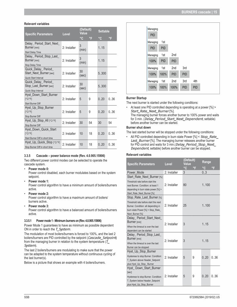
3 .3 .5 .1 Power mode 1 - Minimum burners on (Rev . 4 .0 .905 .15906)Power Mode 1 guarantees to have as minimum as possible dependent ON in order to reach the T_System. The modulation of most boilers/burners is forced to 100%, and the last 2 boilers/burners are PID controlled by the setpoint (Cascade_Setpoint) from the managing burner in relation to the system temperature (T_System). The last 2 boilers/burners are modulating to make sure that the power can be adapted to the system temperature without continuous cycling of the last burner(s). Below is a picture that shows an example with 4 boilers/burners.
Burner Startup The next burner is started under the following conditions: • At least one PID controlled depending is operating at a power [%] >
Start_Rate_Next_Burner [%]. The managing burner forces another burner to 100% power and waits for 3 min. (Delay_Period_Start_Next_Dependent, settable) before another burner can be started.
Burner shut down The last started burner will be stopped under the following conditions:• All PID controlled depending in burn state Power [%] < Stop_Rate_
Last_Burner [%]. The managing burner releases another burner for PID control and waits for 3 min.(Delay_Period_Stop_Next_Dependent, settable) before another burner can be stopped.
Relevant variables
Specific Parameters Level(Default) Value Range
°C °F °C °FPower_Mode 2: Installer 3 0..3Start_Rate_Next_Burner [%]
Threshold rate before start the next Burner. Condition: at least 1 depending in burn state power [%] > Start_Rate_Next_Burner [%]
2: Installer 80 1..100
Stop_Rate_Last_Burner [%]
Threshold rate before start the next Burner. Condition: all depending in burn state Power [%] < Stop_Rate_Next_Burner [%]
2: Installer 25 1..100
Delay_ Period_Start_Next_Burner [min]
When the timeout is over the last dependent can be started
2: Installer 3 1..15
Delay_ Period_Stop_Last_Burner [min]
When the timeout is over the last Burner can be stopped
2: Installer 3 1..15
Hyst_Up_Stop_BurnerHysterese to stop Burner. Condition: T_System above Header_Setpoint plus Hyst_Up_Stop_ Burner
2: Installer 5 9 0..20 0..36
Hyst_ Down_Start_Burner [sec]
Hysterese to stop Burner. Condition: T_System below Header_Setpoint plus Hyst_Up_Stop_Burner
2: Installer 5 9 0..20 0..36

6720892984 (2019/02) US SSB
16 | BURNERS cascade
3 .3 .5 .2 Power mode 2 – Maximum burners on (Rev . 4 .0 .905 .15906)Power mode 2 is designed to have as many depending burners on as possible. When the average burner power of the active depending burners is above a set minimum power, another burner is started.
Burner startup The next burner is started under the following conditions: • When the average burner power of all depending burners is over the
set minimum burner power + hysteresis. − Sum of burner power of all depending [%] > minimum_power [%] * (depending in burn + 1) + minimum_power_hysteresis.
Burner shut down The last started burner will be stopped under the following conditions:• When the average burner power of all depending burners is under the
set minimum burner power. − Sum of burner power of all depending [%] < minimum_power [%] * depending in burn.
Relevant variables
Specific Parameters Level (Default) Value Range
Power_Mode 2: Installer 3 0..3Minimum_Power [%]
Minimum average burner power setting
2: Installer 20 1..100
Minimum_Power_Hysteresis [%]
Hysteresis for the minimum average burner power setting
2: Installer 40 1..100
3 .3 .5 .3 Power mode 3 – Balanced burners on (Rev . 4 .0 .905 .15906)Power mode 3 is designed to have a balanced water flow in systems with a header/manifold.
Burner startup The next burner is started under the following conditions: • When the average burner power of all depending burners is over the
set start rate for the next burner. − Sum of burner power of all depending [%] > Start_Rate_Next_Burner [%] * depending in burn.
Burner shut down The last started burner will be stopped under the following conditions:• When the average burner power of all depending burners is under the
set stop rate for the next burner. − Sum of burner power of all depending [%] < Stop_Rate_Next_Burner [%] * depending in burn.
Relevant variables
Specific Parameters Level(Default) Value Range
°C °F °C °FPower_Mode 2: Installer 3 0..3Start_Rate_Next_Burner [%]
Threshold rate before start the next Burner. Condition: at least 1 depending in burn state power [%] > Start_Rate_Next_Burner [%]
2: Installer 80 1..100
Stop_Rate_Last_Burner [%]
Threshold rate before start the next Burner. Condition: all depending in burn state Power [%] < Stop_Rate_Next_Burner [%]
2: Installer 25 1..100
Delay_ Period_Start_Next_Burner [min]
When the timeout is over the last dependent can be started
2: Installer 3 1..15
Delay_ Period_Stop_Last_Burner [min]
When the timeout is over the last Burner can be stopped
2: Installer 3 1..15
Hyst_Up_Stop_BurnerHysterese to stop Burner. Condition: T_System above Header_Setpoint plus Hyst_Up_Stop_ Burner
2: Installer 5 9 0..20 0..36
Hyst_ Down_Start_Burner [sec]
Hysterese to stop Burner. Condition: T_System below Header_Setpoint plus Hyst_Up_Stop_Burner
2: Installer 5 9 0..20 0..36
SSB 6720892984 (2019/02) US
BURNERS cascade | 17
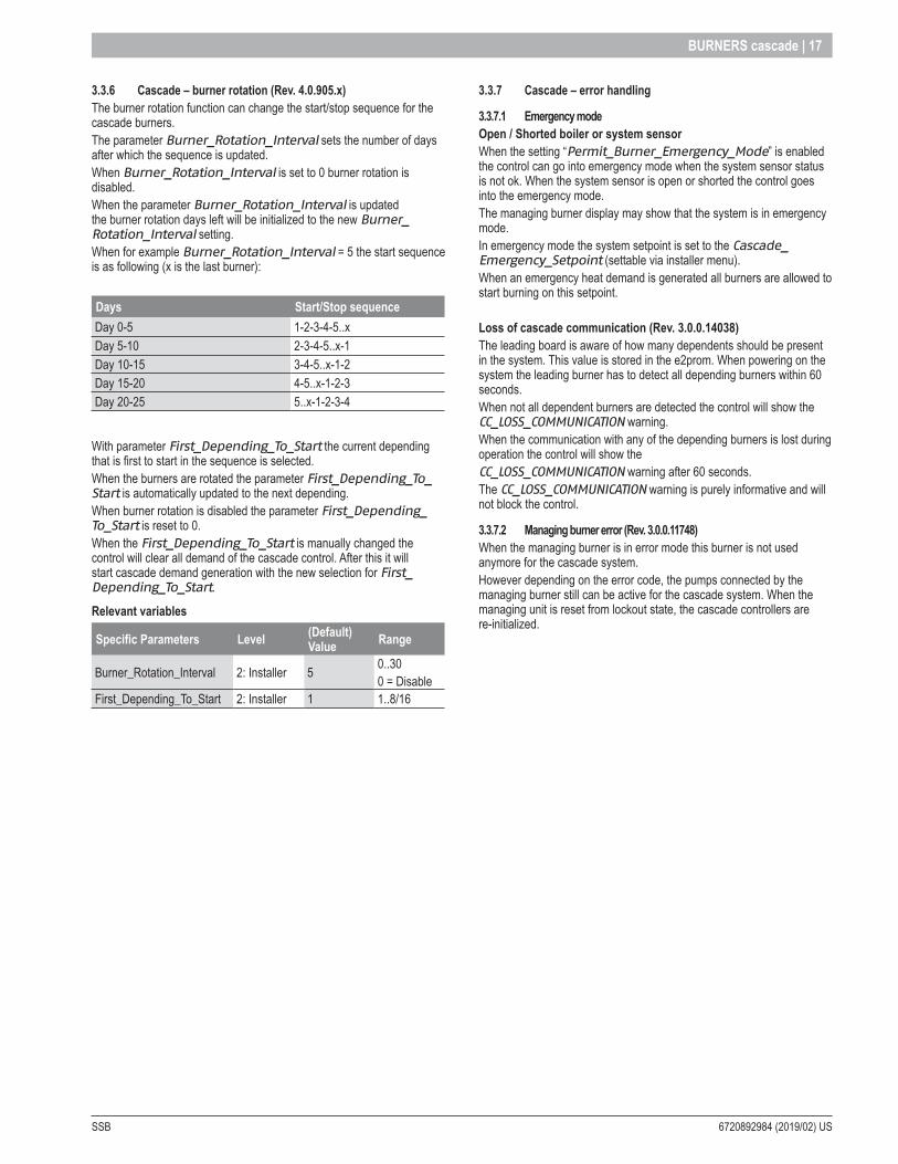
3 .3 .6 Cascade – burner rotation (Rev . 4 .0 .905 .x)The burner rotation function can change the start/stop sequence for the cascade burners. The parameter Burner_Rotation_Interval sets the number of days after which the sequence is updated. When Burner_Rotation_Interval is set to 0 burner rotation is disabled. When the parameter Burner_Rotation_Interval is updated the burner rotation days left will be initialized to the new Burner_Rotation_Interval setting. When for example Burner_Rotation_Interval = 5 the start sequence is as following (x is the last burner):
Days Start/Stop sequenceDay 0-5 1-2-3-4-5..xDay 5-10 2-3-4-5..x-1Day 10-15 3-4-5..x-1-2Day 15-20 4-5..x-1-2-3Day 20-25 5..x-1-2-3-4
With parameter First_Depending_To_Start the current depending that is first to start in the sequence is selected. When the burners are rotated the parameter First_Depending_To_Start is automatically updated to the next depending. When burner rotation is disabled the parameter First_Depending_To_Start is reset to 0. When the First_Depending_To_Start is manually changed the control will clear all demand of the cascade control. After this it will start cascade demand generation with the new selection for First_Depending_To_Start.
Relevant variables
Specific Parameters Level (Default) Value Range
Burner_Rotation_Interval 2: Installer 5 0..300 = Disable
First_Depending_To_Start 2: Installer 1 1..8/16
3 .3 .7 Cascade – error handling
3 .3 .7 .1 Emergency modeOpen / Shorted boiler or system sensor When the setting “Permit_Burner_Emergency_Mode” is enabled the control can go into emergency mode when the system sensor status is not ok. When the system sensor is open or shorted the control goes into the emergency mode. The managing burner display may show that the system is in emergency mode. In emergency mode the system setpoint is set to the Cascade_Emergency_Setpoint (settable via installer menu). When an emergency heat demand is generated all burners are allowed to start burning on this setpoint.
Loss of cascade communication (Rev . 3 .0 .0 .14038) The leading board is aware of how many dependents should be present in the system. This value is stored in the e2prom. When powering on the system the leading burner has to detect all depending burners within 60 seconds. When not all dependent burners are detected the control will show the CC_LOSS_COMMUNICATION warning. When the communication with any of the depending burners is lost during operation the control will show the CC_LOSS_COMMUNICATION warning after 60 seconds. The CC_LOSS_COMMUNICATION warning is purely informative and will not block the control.
3 .3 .7 .2 Managing burner error (Rev . 3 .0 .0 .11748)When the managing burner is in error mode this burner is not used anymore for the cascade system. However depending on the error code, the pumps connected by the managing burner still can be active for the cascade system. When the managing unit is reset from lockout state, the cascade controllers are re-initialized.

6720892984 (2019/02) US SSB
18 | Service display
4 Service display
4 .1 General4 .1 .1 IntroductionThe 900PB Display is an advanced graphical user interface for applications such as HMI for heating appliances.It can be used in combination with other epHS controls and communicates with these controls via the AL-BUS connection.This manual is applicable for layout versions: • 900PB06_3R
4 .1 .2 General information
Dimensions PCB L × W × H
900PB0X_3R: 178x85x13mm (7,01”x3,35”x0,51”)
Operating temperature 0°C to +50°C (32°F to 122°F)
Connections See “Appendix J - PB Connectors Description” pag. 65
LCD mode 255 x 80 Dot graphic
Module dimensions W × H × T
121,4x47,6x5,0mm (4,78”x1,87”x0,2”)
Viewing area W × H 106,4 x 39,0mm (4,19”x1,54”)
Active area W × H 95,0 x 32,0mm (3,74”x1,26”)
Dot size W × H 0.34 x 0.37Dot pitch W × H 0.37 x 0.40LCD display mode TN/Blue/Negative/Transflective Viewing direction 12 O’clock
900PB06_3R:
85
178
1 = 1 mm
4 .1 .3 Display functions Button FunctionRESET Reset Lockout errorMENU Enter the main menuESC Return to the Status overviewLEFT Return to previous menu item or Status overview
RIGHT Enter a menu item or confirm selection in Status overview (when directly setting Actual setpoint or DHW setpoint)
ENTER Confirm a setting or enter a menu item
UPDirectly select Actual setpoint of DHW setpoint in the Status overview, push RIGHT to confirm and use UP or DOWN to adjust value
DOWNDirectly select Actual setpoint of DHW setpoint in the Status overview, push RIGHT to confirm and use UP or DOWN to adjust value
RESET MENU ESC DOWN
RIGHTLEFT
ENTER
UP
4 .1 .4 Display icons The following table gives a short description of the icons that can be visible on the main screen during operating:
Icon Description
Central Heating demand
Domestic Hot Water demand
Indicates that the appliance burner is ON
Cascade Emergency Mode active
Error notification
SSB 6720892984 (2019/02) US
Service display | 19
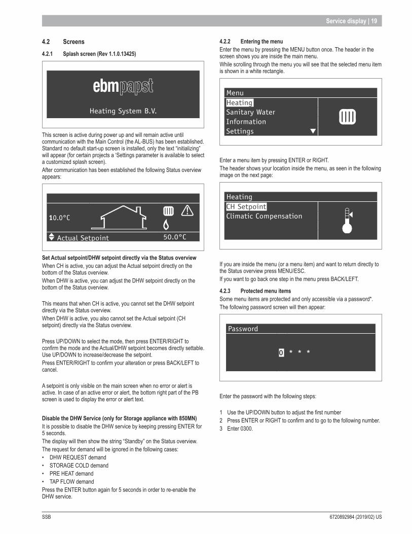
4 .2 Screens 4 .2 .1 Splash screen (Rev 1 .1 .0 .13425)
Heating System B.V.
This screen is active during power up and will remain active until communication with the Main Control (the AL-BUS) has been established. Standard no default start-up screen is installed, only the text “initializing” will appear (for certain projects a ‘Settings parameter is available to select a customized splash screen).After communication has been established the following Status overview appears:
10.0°C
Actual Setpoint 50.0°C
Set Actual setpoint/DHW setpoint directly via the Status overviewWhen CH is active, you can adjust the Actual setpoint directly on the bottom of the Status overview.When DHW is active, you can adjust the DHW setpoint directly on the bottom of the Status overview.
This means that when CH is active, you cannot set the DHW setpoint directly via the Status overview.When DHW is active, you also cannot set the Actual setpoint (CH setpoint) directly via the Status overview.
Press UP/DOWN to select the mode, then press ENTER/RIGHT to confirm the mode and the Actual/DHW setpoint becomes directly settable. Use UP/DOWN to increase/decrease the setpoint.Press ENTER/RIGHT to confirm your alteration or press BACK/LEFT to cancel.
A setpoint is only visible on the main screen when no error or alert is active. In case of an active error or alert, the bottom right part of the PB screen is used to display the error or alert text.
Disable the DHW Service (only for Storage appliance with 850MN)It is possible to disable the DHW service by keeping pressing ENTER for 5 seconds.The display will then show the string “Standby” on the Status overview.The request for demand will be ignored in the following cases:• DHW REQUEST demand• STORAGE COLD demand• PRE HEAT demand• TAP FLOW demandPress the ENTER button again for 5 seconds in order to re-enable the DHW service.
4 .2 .2 Entering the menu Enter the menu by pressing the MENU button once. The header in the screen shows you are inside the main menu.While scrolling through the menu you will see that the selected menu item is shown in a white rectangle.
MenuHeating Sanitary WaterInformationSettings
Enter a menu item by pressing ENTER or RIGHT.The header shows your location inside the menu, as seen in the following image on the next page:
HeatingCH Setpoint Climatic Compensation
If you are inside the menu (or a menu item) and want to return directly to the Status overview press MENU/ESC.If you want to go back one step in the menu press BACK/LEFT.
4 .2 .3 Protected menu items Some menu items are protected and only accessible via a password*.The following password screen will then appear:
Password
0 * * *
Enter the password with the following steps:
1 Use the UP/DOWN button to adjust the first number2 Press ENTER or RIGHT to confirm and to go to the following number.3 Enter 0300.
6720892984 (2019/02) US SSB
20 | Service display
Repeat this action for all numbers to enter the password.During this action, if you want to return to the previous screen, just press MENU or ESC to cancel.After the password is entered in correctly, the menu item will become available.The following menu items require a password*:
(Sub) Menu item Location inside menuClimatic Compensation via ‘Heating > Climatic compensation’Boiler via ‘Settings > Boiler’
* Passwords for different user levels are always customer specific and will be provided by epHS to the appliance manufacturer only (due to safety reasons).
4 .2 .4 DAir SequenceThe “De-Air” sequence is a safety function that starts at every power ON and is used to remove the air from the heater-exchanger.The DAir sequence does not start after a general reset (like the locking error reset or 24 hours reset)
The display will show the following string during DAir sequence:• “Dair Running”• “Dair Error Water Pressure”
The DAir sequence can be canceled by the user by pressing the OK button for over 5 seconds.
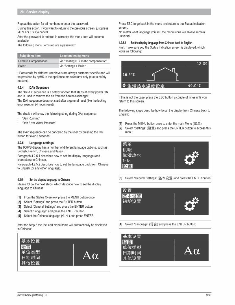
4 .2 .5 Language settingsThe 900PB display has a number of different language options, such as English, French, Chinese and Italian.Paragraph 4.2.5.1 describes how to set the display language (and characters) to Chinese.Paragraph 4.2.5.2 describes how to set the language back from Chinese to English (or any other language).
4 .2 .5 .1 Set the display language to Chinese Please follow the next steps, which describe how to set the display language to Chinese:
[1] From the Status Overview, press the MENU button once[2] Select “Settings” and press the ENTER button[3] Select “General Settings” and press the ENTER button[4] Select “Language” and press the ENTER button[5] Select the Chinese language (中文) and press ENTER
After the Step 5 the text and menu items will automatically be displayed in Chinese:
基本设置
语言
Aα单位类型
日期时间
其他设置
Press ESC to go back in the menu and return to the Status Indication screen.No matter what language you set, the menu icons will always remain universal.
4 .2 .5 .2 Set the display language from Chinese back to EnglishFirst, make sure you the Status Indication screen is displayed, which looks as following:
12 09
16.5°C
生活热水温度设定 49.0°C
If this is not the case, press the ESC button a couple of times until you return to this screen.
The following steps describe how to set the display from Chinese back to English:
[1] Press the MENU button once to enter the main Menu (菜单)[2] Select “Settings” (设置) and press the ENTER button to access this
menu:
菜单
供暖
生活热水
Info设置
[3] Select “General Settings” (基本设置) and press the ENTER button:
设置
基本设置
锅炉设置
[4] Select “Language” (语言) and press the ENTER button:
基本设置
语言
Aα单位类型
日期时间
其他设置

SSB 6720892984 (2019/02) US
Service display | 21
[5] Select the desired language (“English“) and press ENTER to confirm: (For setting the display to French: select “Français”, for Italian select “Italiano”)
语言
EnglishFrançais中文
Italiano
Once you have set the English language, the screen will display its information in English again:
General settingLanguage
AαUnit TypeDate & TimeOther Setting
Press ESC to go back in the menu and return to the Status Indication screen.
6720892984 (2019/02) US SSB
22 | Service display
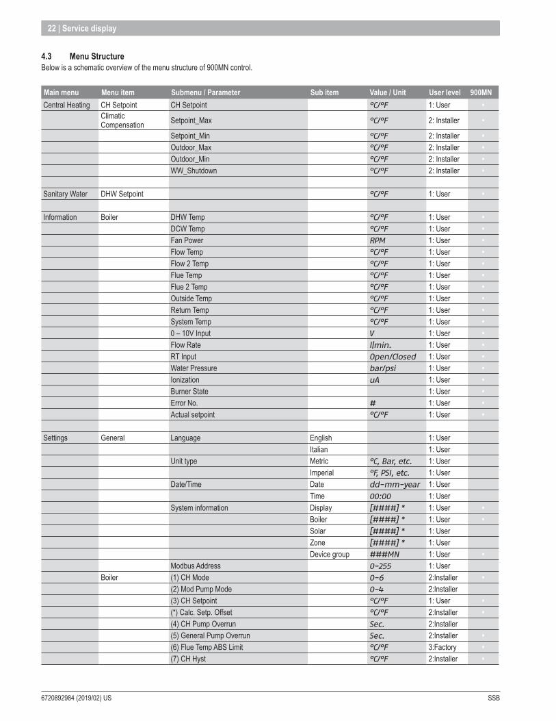
4 .3 Menu StructureBelow is a schematic overview of the menu structure of 900MN control.
Main menu Menu item Submenu / Parameter Sub item Value / Unit User level 900MNCentral Heating CH Setpoint CH Setpoint °C/°F 1: User •
Climatic Compensation Setpoint_Max °C/°F 2: Installer •
Setpoint_Min °C/°F 2: Installer •Outdoor_Max °C/°F 2: Installer •Outdoor_Min °C/°F 2: Installer •WW_Shutdown °C/°F 2: Installer •
Sanitary Water DHW Setpoint °C/°F 1: User •
Information Boiler DHW Temp °C/°F 1: User •DCW Temp °C/°F 1: User •Fan Power RPM 1: User •Flow Temp °C/°F 1: User •Flow 2 Temp °C/°F 1: User •Flue Temp °C/°F 1: User •Flue 2 Temp °C/°F 1: User •Outside Temp °C/°F 1: User •Return Temp °C/°F 1: User •System Temp °C/°F 1: User •0 – 10V Input V 1: User •Flow Rate l|min. 1: User •RT Input Open/Closed 1: User •Water Pressure bar/psi 1: User •Ionization uA 1: User •Burner State 1: User •Error No. # 1: User •Actual setpoint °C/°F 1: User •
Settings General Language English 1: UserItalian 1: User
Unit type Metric °C, Bar, etc. 1: UserImperial °F, PSI, etc. 1: User
Date/Time Date dd-mm-year 1: UserTime 00:00 1: User
System information Display [####] * 1: User •Boiler [####] * 1: User •Solar [####] * 1: UserZone [####] * 1: UserDevice group ###MN 1: User •
Modbus Address 0-255 1: UserBoiler (1) CH Mode 0-6 2:Installer •
(2) Mod Pump Mode 0-4 2:Installer(3) CH Setpoint °C/°F 1: User •(*) Calc. Setp. Offset °C/°F 2:Installer •(4) CH Pump Overrun Sec. 2:Installer(5) General Pump Overrun Sec. 2:Installer •(6) Flue Temp ABS Limit °C/°F 3:Factory •(7) CH Hyst °C/°F 2:Installer •

SSB 6720892984 (2019/02) US
Service display | 23
Main menu Menu item Submenu / Parameter Sub item Value / Unit User level 900MN(7) CH Hyst Up °C/°F 2:Installer •(*) CH Hyst Down °C/°F 2:Installer •
* Checksum software version
Main menu Menu item Submenu / Parameter Sub item Value / Unit User level 900MN(8) Flue Gas Diff °C/°F 3: Factory(9) Anti Cycle Period Sec. 2: Installer •(10) Anti Cycle T Diff °C/°F 2: Installer •(11) Ramp Delay Step Mod On/Off 2: Installer(12) Hx Diff Delta Tmin °C/°F 3: Factory •(13) Hx Diff Max Wait Time Sec. 3: Factory •(14) P CH Max % 2: Installer •(15) P CH Min % 2: Installer •(16) CH PID P 3: Factory •(17) CH PID I 3: Factory •(18) CH PID D 3: Factory •(19) High CH Setpoint °C/°F 2: Installer •(20) Outdoor Temp For Hi Setp °C/°F 2: Installer •(21) Low CH Setpoint °C/°F 2: Installer •(22) Outdoor Temp For Lo Setp °C/°F 2: Installer •(23) CH Setpoint Min. °C/°F 2: Installer •(24) CH Setpoint Max. °C/°F 2: Installer •(25) Warm Weather Shutdown °C/°F 2: Installer •(26) Boost Temp. Incr. °C/°F 2: Installer •(27) Boost Time Delay Min. 2: Installer •(28) Night Setback Temp. °C/°F 2: Installer •(29) Weather Setpoint °C/°F 2: Installer(30) HydroAir CH Hyst Down °C/°F 3: Factory(31) HydroAir CH Hyst Up °C/°F 3: Factory(32) HydroAir CH PID P 3: Factory(33) HydroAir CH PID I 3: Factory(34) HydroAir CH PID D 3: Factory(35) DHW Mode 0-5 2: Installer •(*) P DHW Max % 2: Installer •(*) P DHW Min % 2: Installer •(36) DHW Storage Hyst Dn °C/°F 2: Installer •(37) DHW Storage Hyst Up °C/°F 2: Installer •(38) DHW Store Supply Extra °C/°F 2: Installer •(39) DHW Store Supp Hyst Dn °C/°F 3: Factory •(40) DHW Store Supp Hyst Up °C/°F 3: Factory •(41) DHW Store Hold Warm °C/°F 3: Factory •(42) DHW Priority 0-2 2: Installer •(43) DHW Max Priority Time Min. 2: Installer •(44) Post Pump DHW Time Sec. 2: Installer •(45) DHW Store PID P 3: Factory •(46) DHW Store PID I 3: Factory •(47) DHW Store PID D 3: Factory •(48) DHW Setpoint °C/°F 1: User •(49) DHW Hysterese Down °C/°F 3: Factory •(50) DHW Hysterese Up °C/°F 3: Factory •(51) DHW Instant PID P 3: Factory •

6720892984 (2019/02) US SSB
24 | Service display
Main menu Menu item Submenu / Parameter Sub item Value / Unit User level 900MN(52) DHW Instant PID I 3: Factory •(53) DHW Instant PID D 3:Factory •(54) Tap Detect DHW Drop °C/°F 3:Factory(55) Tap Detect Hyst Dn °C/°F 3:Factory(56) TapFlow Max Time Sec. 3:Factory(57) Tap Det Hold Active Time Sec. 3:Factory(58) Tap Det Stop Diff SupRet °C/°F 3:Factory(59) Tap Det Stop Diff RetDhw °C/°F 3:Factory(60) Flow Rate Start l/min / gpm 3:Factory •(61) Flow Rate Lo Temp Pwr l/min / gpm 3:Factory •(62) Flow Rate Hi Temp Pwr l/min / gpm 3:Factory •(63) DHW On Off Period Sec. 3:Factory •(64) PH Mode Comfort, Eco 1:User •(65) PH Eco Setpoint °C/°F 3:Factory •(66) PH Hold Time Sec. 3:Factory(67) PH After Tap Hold Time Sec. 3:Factory •(68) After Tap Hold Time Sec. 3:Factory •(69) PreHeat Hyst Down °C/°F 3:Factory •(70) PreHeat Hyst Up °C/°F 3:Factory •(71) PreHeat Delay Time Sec. 3:Factory •(72) Permit EmergencyMode Yes/No 1:User •(73) Boiler Address 0-16 2:Installer •(74) Cas Emergency Setpoint °C/°F 2:Installer •(75) Delay Per Start Next Dep Sec. 2:Installer •(76) Delay Per Stop Next Dep Sec. 2:Installer •(*) Delay Per Quick Start Next Dep Sec. 2:Installer •(*) Delay Per Quick Start Next Dep Sec. 2:Installer •(77) Hyst Down Start Boiler °C/°F 2:Installer •(78) Hyst Up Stop Boiler °C/°F 2:Installer •(*) Hyst Down Quick Start Boiler °C/°F 2:Installer •(*) Hyst Up Quick Stop Boiler °C/°F 2:Installer •(*) Hyst Up Stop All Boilers °C/°F 2:Installer •(79) Max Setp Offset Down °C/°F 2:Installer •(80) Max Setp Offset Up °C/°F 2:Installer •(81) Start Mod Delay Fact Min. 2:Installer •(82) Next Boiler Start Rate % 2:Installer •(83) Next Boiler Stop Rate % 2:Installer •(84) Boiler Rotation Interval Days 2:Installer •(*) Boiler First to Start 2:Installer •(85) DHW Boiler Assign 0-16 2:Installer(86) Casc PID P 3:Factory •(87) Casc PID I 3:Factory •(88) Casc PID Slew Rate 3:Factory(*) Casc PID Slew Rate Up 3:Factory •(*) Casc PID Slew Rate Down 3:Factory •(89) Frost Protection On/Off 2:Installer(90) Frost Protection Setpoint °C/°F 2:Installer(91) DHW Max Setpoint °C/°F 2:Installer(92) Fan Speed Maximum RPM 2:Installer •(93) Fan Speed Minimum RPM 2:Installer •(94) Fan Speed Ignition RPM 2:Installer •(95) Gas Type 0-4 3:Factory
SSB 6720892984 (2019/02) US
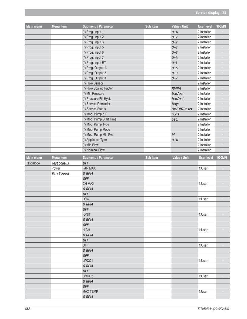
Service display | 25
Main menu Menu item Submenu / Parameter Sub item Value / Unit User level 900MN(*) Prog. Input 1. 0-4 2:Installer •(*) Prog. Input 2. 0-2 2:Installer •(*) Prog. Input 3. 0-2 2:Installer •(*) Prog. Input 5. 0-2 2:Installer •(*) Prog. Input 6. 0-3 2:Installer •(*) Prog. Input 7. 0-4 2:Installer •(*) Prog. Input RT. 0-1 2:Installer •(*) Prog. Output 1. 0-5 2:Installer •(*) Prog. Output 2. 0-3 2:Installer •(*) Prog. Output 3. 0-2 2:Installer •(*) Flow Sensor 2:Installer •(*) Flow Scaling Factor RMP/l 2:Installer •(*) Min Pressure bar/psi 2:Installer •(*) Pressure Fill Hyst. bar/psi 2:Installer •(*) Service Reminder Days 2:Installer •(*) Service Status On/Off/Reset 2:Installer •(*) Mod. Pump dT °C/°F 2:Installer •(*) Mod. Pump Start Time Sec. 2:Installer •(*) Mod. Pump Type 2:Installer •(*) Mod. Pump Mode 2:Installer •(*) Mod. Pump Min Pwr % 2:Installer •(*) Appliance Type 0-4 2:Installer •(*) Min Flow 2:Installer •(*) Nominal Flow 2:Installer •
Main menu Menu item Submenu / Parameter Sub item Value / Unit User level 900MNTest mode Test Status OFF
Power FAN MAX 1:User •Fan Speed O RPM
OFFCH MAX 1:User •O RPMOFFLOW 1:User •O RPMOFFIGNIT 1:User •O RPMOFFHIGH 1:User •O RPMOFFOFF 1:User •O RPMOFFLWCO1 1:User •O RPMOFFLWCO2 1:User •O RPMOFFMAX TEMP 1:User •O RPM
6720892984 (2019/02) US SSB
26 | Main control
5 Main control
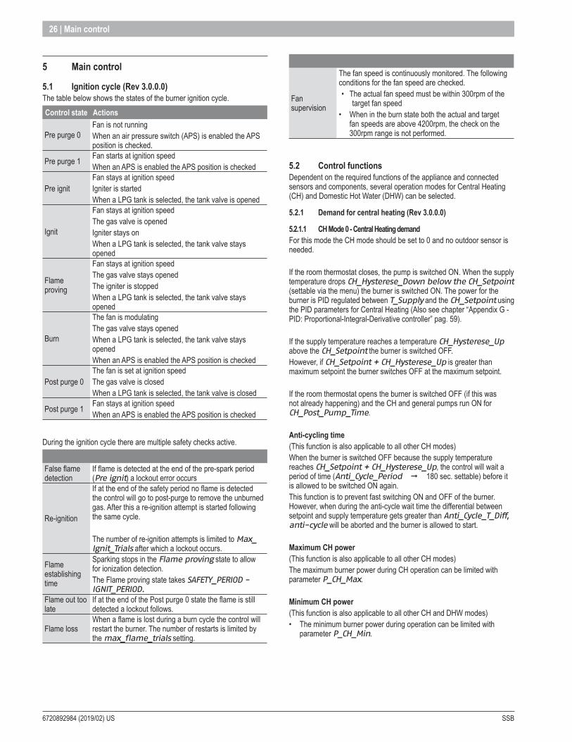
5 .1 Ignition cycle (Rev 3 .0 .0 .0)The table below shows the states of the burner ignition cycle.Control state Actions
Pre purge 0Fan is not running When an air pressure switch (APS) is enabled the APS position is checked.
Pre purge 1 Fan starts at ignition speedWhen an APS is enabled the APS position is checked
Pre ignitFan stays at ignition speed Igniter is started When a LPG tank is selected, the tank valve is opened
Ignit
Fan stays at ignition speed The gas valve is opened Igniter stays onWhen a LPG tank is selected, the tank valve stays opened
Flame proving
Fan stays at ignition speedThe gas valve stays openedThe igniter is stoppedWhen a LPG tank is selected, the tank valve stays opened
Burn
The fan is modulating The gas valve stays opened When a LPG tank is selected, the tank valve stays openedWhen an APS is enabled the APS position is checked
Post purge 0The fan is set at ignition speed The gas valve is closed When a LPG tank is selected, the tank valve is closed
Post purge 1 Fan stays at ignition speed When an APS is enabled the APS position is checked
During the ignition cycle there are multiple safety checks active.
False flame detection
If flame is detected at the end of the pre-spark period (Pre ignit) a lockout error occurs
Re-ignition
If at the end of the safety period no flame is detected the control will go to post-purge to remove the unburned gas. After this a re-ignition attempt is started following the same cycle.
The number of re-ignition attempts is limited to Max_Ignit_Trials after which a lockout occurs.
Flame establishing time
Sparking stops in the Flame proving state to allow for ionization detection. The Flame proving state takes SAFETY_PERIOD - IGNIT_PERIOD.
Flame out too late
If at the end of the Post purge 0 state the flame is still detected a lockout follows.
Flame lossWhen a flame is lost during a burn cycle the control will restart the burner. The number of restarts is limited by the max_flame_trials setting.
Fan supervision
The fan speed is continuously monitored. The following conditions for the fan speed are checked.• The actual fan speed must be within 300rpm of the
target fan speed• When in the burn state both the actual and target
fan speeds are above 4200rpm, the check on the 300rpm range is not performed.
5 .2 Control functionsDependent on the required functions of the appliance and connected sensors and components, several operation modes for Central Heating (CH) and Domestic Hot Water (DHW) can be selected.
5 .2 .1 Demand for central heating (Rev 3 .0 .0 .0)
5 .2 .1 .1 CH Mode 0 - Central Heating demandFor this mode the CH mode should be set to 0 and no outdoor sensor is needed.
If the room thermostat closes, the pump is switched ON. When the supply temperature drops CH_Hysterese_Down below the CH_Setpoint (settable via the menu) the burner is switched ON. The power for the burner is PID regulated between T_Supply and the CH_Setpoint using the PID parameters for Central Heating (Also see chapter “Appendix G - PID: Proportional-Integral-Derivative controller” pag. 59).
If the supply temperature reaches a temperature CH_Hysterese_Up above the CH_Setpoint the burner is switched OFF.However, if CH_Setpoint + CH_Hysterese_Up is greater than maximum setpoint the burner switches OFF at the maximum setpoint.
If the room thermostat opens the burner is switched OFF (if this was not already happening) and the CH and general pumps run ON for CH_Post_Pump_Time.
Anti-cycling time(This function is also applicable to all other CH modes)When the burner is switched OFF because the supply temperature reaches CH_Setpoint + CH_Hysterese_Up, the control will wait a period of time (Anti_Cycle_Period ¨ 180 sec. settable) before it is allowed to be switched ON again.This function is to prevent fast switching ON and OFF of the burner. However, when during the anti-cycle wait time the differential between setpoint and supply temperature gets greater than Anti_Cycle_T_Diff, anti-cycle will be aborted and the burner is allowed to start.
Maximum CH power(This function is also applicable to all other CH modes)The maximum burner power during CH operation can be limited with parameter P_CH_Max.
Minimum CH power(This function is also applicable to all other CH and DHW modes)• The minimum burner power during operation can be limited with
parameter P_CH_Min.
SSB 6720892984 (2019/02) US
Main control | 27
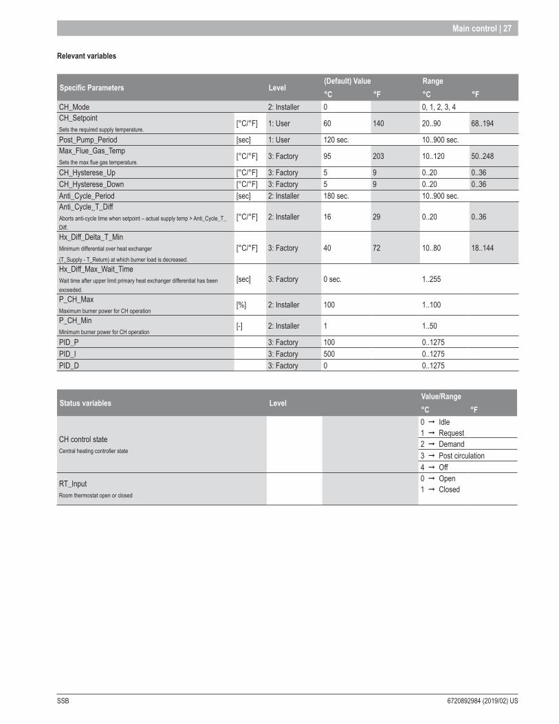
Relevant variables
Specific Parameters Level(Default) Value Range°C °F °C °F
CH_Mode 2: Installer 0 0, 1, 2, 3, 4CH_SetpointSets the required supply temperature.
[°C/°F] 1: User 60 140 20..90 68..194
Post_Pump_Period [sec] 1: User 120 sec. 10..900 sec.Max_Flue_Gas_TempSets the max flue gas temperature.
[°C/°F] 3: Factory 95 203 10..120 50..248
CH_Hysterese_Up [°C/°F] 3: Factory 5 9 0..20 0..36CH_Hysterese_Down [°C/°F] 3: Factory 5 9 0..20 0..36Anti_Cycle_Period [sec] 2: Installer 180 sec. 10..900 sec.Anti_Cycle_T_DiffAborts anti-cycle time when setpoint – actual supply temp > Anti_Cycle_T_Diff.
[°C/°F] 2: Installer 16 29 0..20 0..36
Hx_Diff_Delta_T_MinMinimum differential over heat exchanger
(T_Supply - T_Return) at which burner load is decreased.
[°C/°F] 3: Factory 40 72 10..80 18..144
Hx_Diff_Max_Wait_TimeWait time after upper limit primary heat exchanger differential has been exceeded.
[sec] 3: Factory 0 sec. 1..255
P_CH_MaxMaximum burner power for CH operation
[%] 2: Installer 100 1..100
P_CH_MinMinimum burner power for CH operation
[-] 2: Installer 1 1..50
PID_P 3: Factory 100 0..1275PID_I 3: Factory 500 0..1275PID_D 3: Factory 0 0..1275
Status variables LevelValue/Range°C °F
CH control stateCentral heating controller state
0 ¨ Idle1 ¨ Request2 ¨ Demand3 ¨ Post circulation4 ¨ Off
RT_InputRoom thermostat open or closed
0 ¨ Open1 ¨ Closed
6720892984 (2019/02) US SSB
28 | Main control
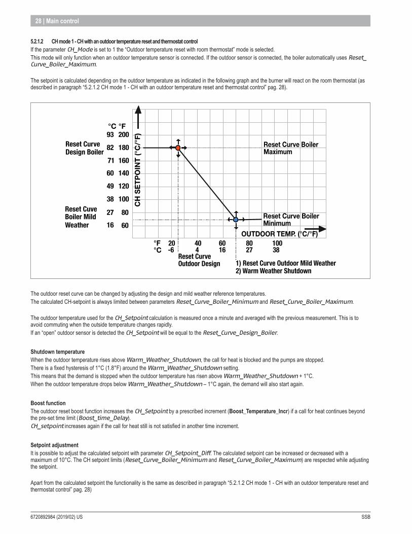
5 .2 .1 .2 CH mode 1 - CH with an outdoor temperature reset and thermostat controlIf the parameter CH_Mode is set to 1 the “Outdoor temperature reset with room thermostat” mode is selected.This mode will only function when an outdoor temperature sensor is connected. If the outdoor sensor is connected, the boiler automatically uses Reset_Curve_Boiler_Maximum.
The setpoint is calculated depending on the outdoor temperature as indicated in the following graph and the burner will react on the room thermostat (as described in paragraph “5.2.1.2 CH mode 1 - CH with an outdoor temperature reset and thermostat control” pag. 28).
20
OUTDOOR TEMP. (°C/°F)
Reset CurveDesign Boiler
93
Reset Curve Outdoor Design 1) Reset Curve Outdoor Mild Weather
2) Warm Weather Shutdown
Reset Cuve Boiler MildWeather
Reset Curve BoilerMaximum
200
82 180
71 16060 140
12049
10038
27 80
6016
°C °F
-6404
6016
8027
10038
°F°C
Reset Curve BoilerMinimum
CH
SET
POIN
T (°C
/°F)
The outdoor reset curve can be changed by adjusting the design and mild weather reference temperatures.The calculated CH-setpoint is always limited between parameters Reset_Curve_Boiler_Minimum and Reset_Curve_Boiler_Maximum.
The outdoor temperature used for the CH_Setpoint calculation is measured once a minute and averaged with the previous measurement. This is to avoid commuting when the outside temperature changes rapidly.If an “open” outdoor sensor is detected the CH_Setpoint will be equal to the Reset_Curve_Design_Boiler.
Shutdown temperatureWhen the outdoor temperature rises above Warm_Weather_Shutdown, the call for heat is blocked and the pumps are stopped.There is a fixed hysteresis of 1°C (1.8°F) around the Warm_Weather_Shutdown setting.This means that the demand is stopped when the outdoor temperature has risen above Warm_Weather_Shutdown + 1°C.When the outdoor temperature drops below Warm_Weather_Shutdown – 1°C again, the demand will also start again.
Boost functionThe outdoor reset boost function increases the CH_Setpoint by a prescribed increment (Boost_Temperature_Incr) if a call for heat continues beyond the pre-set time limit (Boost_time_Delay).CH_setpoint increases again if the call for heat still is not satisfied in another time increment.
Setpoint adjustmentIt is possible to adjust the calculated setpoint with parameter CH_Setpoint_Diff. The calculated setpoint can be increased or decreased with a maximum of 10°C. The CH setpoint limits (Reset_Curve_Boiler_Minimum and Reset_Curve_Boiler_Maximum) are respected while adjusting the setpoint.
Apart from the calculated setpoint the functionality is the same as described in paragraph “5.2.1.2 CH mode 1 - CH with an outdoor temperature reset and thermostat control” pag. 28)

SSB 6720892984 (2019/02) US
Main control | 29
CH Setpoint calculated with an extra correctionThe calculated setpoint based on the outdoor temperature can also be adjusted with another correction. The generation of thisextra correction is a result of a not linear computation.
The new setpoint is calculated as follow:New CH calculated setpoint (@Outdoor_temp)= CH calculated setpoint (@Outdoor_temp) – extra correction (@Outdoor_temp)The parameter used for the extra compensation is E2_CH_Reset_Curve_Comp .
20
CH S
ETPO
INT
(°C
/)
°F
OUTDOOR TEMP. (°C/ )°F
Reset CurveDesign Boiler
93
Reset Curve Outdoor Design1)Reset Curve Outdoor Mild Weather2) Warm Weather Shutdown
Reset Cuve Boiler MildWeather
Reset Curve Boiler Maximum
200
82 180
71 160
60 140
12049
10038
27 80
6016
°C °F
-6404
6016
8027
10038
°F°C
Reset Curve Boiler Minimum
CH outdoor reset curve in red color and CH outdoor reset Curve with extra compensation in blue
Relevant variables
Specific Parameters Level(Default) Value Settable°C °F °C °F
CH_Mode 2: Installer 0 0, 1, 2, 3, 4CH_Hysterese_Up [°C/°F] 3. Factory 5 9 0..20 0..36CH_Hysterese_Down [°C/°F] 3. Factory 5 9 0..20 0..36Reset_Curve_Boiler_MinimumSets the lower limit for the CH setpoint (minimum).
[°C/°F] 2: Installer 30 86 4..82 39..180
Reset_Curve_Boiler_MaximumSets the upper limit for the CH setpoint (maximum).
[°C/°F] 2: Installer 80 176 27..90 81..194
Reset_Curve_Design_BoilerSets high boiler CH setpoint when outdoor temp. is equal to Reset_Curve_Outdoor_Design. The range for this parameter is limited by the Reset_Curve_Boiler_Minimum and Reset_Curve_Boiler_Maximum parameters!
[°C/°F] 2: Installer 80 176
Reset_Curve_Outdoor_DesignSets the outdoor temp at which the boiler setpoint must be high as set by Reset_Curve_Design_Boiler.
[°C/°F] 2: Installer -5 23 -20..25 -13..77
Reset_Curve_Boiler_Mild_WeatherSets low boiler CH setpoint when outdoor temp. is equal to Reset_Curve_Outdoor_Mild_Weather. The range for this parameter is limited by the Reset_Curve_Boiler_Minimum and Reset_Curve_Boiler_Maximum parameters!
[°C/°F] 2: Installer 40 104
Reset_Curve_Outdoor_Mild_WeatherSets the outdoor temp at which the boiler setpoint must be low as set by Reset_Curve_Mild_Weather.
[°C/°F] 2: Installer 20 68 0..30 32..86
6720892984 (2019/02) US SSB
30 | Main control
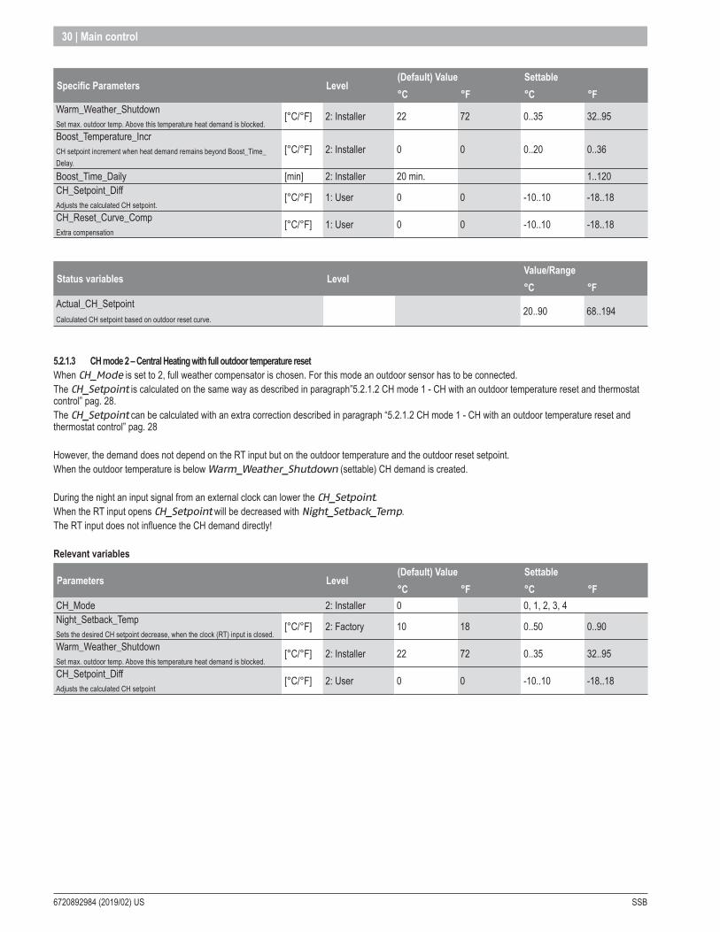
Specific Parameters Level(Default) Value Settable°C °F °C °F
Warm_Weather_ShutdownSet max. outdoor temp. Above this temperature heat demand is blocked.
[°C/°F] 2: Installer 22 72 0..35 32..95
Boost_Temperature_IncrCH setpoint increment when heat demand remains beyond Boost_Time_Delay.
[°C/°F] 2: Installer 0 0 0..20 0..36
Boost_Time_Daily [min] 2: Installer 20 min. 1..120CH_Setpoint_DiffAdjusts the calculated CH setpoint.
[°C/°F] 1: User 0 0 -10..10 -18..18
CH_Reset_Curve_CompExtra compensation
[°C/°F] 1: User 0 0 -10..10 -18..18
Status variables LevelValue/Range°C °F
Actual_CH_Setpoint20..90 68..194
Calculated CH setpoint based on outdoor reset curve.
5 .2 .1 .3 CH mode 2 – Central Heating with full outdoor temperature resetWhen CH_Mode is set to 2, full weather compensator is chosen. For this mode an outdoor sensor has to be connected.The CH_Setpoint is calculated on the same way as described in paragraph”5.2.1.2 CH mode 1 - CH with an outdoor temperature reset and thermostat control” pag. 28.The CH_Setpoint can be calculated with an extra correction described in paragraph “5.2.1.2 CH mode 1 - CH with an outdoor temperature reset and thermostat control” pag. 28
However, the demand does not depend on the RT input but on the outdoor temperature and the outdoor reset setpoint.When the outdoor temperature is below Warm_Weather_Shutdown (settable) CH demand is created.
During the night an input signal from an external clock can lower the CH_Setpoint.When the RT input opens CH_Setpoint will be decreased with Night_Setback_Temp.The RT input does not influence the CH demand directly!
Relevant variables
Parameters Level(Default) Value Settable°C °F °C °F
CH_Mode 2: Installer 0 0, 1, 2, 3, 4Night_Setback_TempSets the desired CH setpoint decrease, when the clock (RT) input is closed.
[°C/°F] 2: Factory 10 18 0..50 0..90
Warm_Weather_ShutdownSet max. outdoor temp. Above this temperature heat demand is blocked.
[°C/°F] 2: Installer 22 72 0..35 32..95
CH_Setpoint_DiffAdjusts the calculated CH setpoint
[°C/°F] 2: User 0 0 -10..10 -18..18
SSB 6720892984 (2019/02) US
Main control | 31
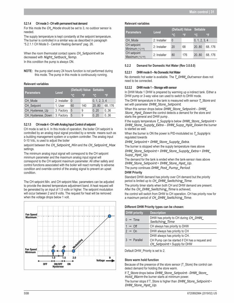
5 .2 .1 .4 CH mode 3 - CH with permanent heat demandFor this mode the CH_Mode should be set to 3, no outdoor sensor is needed.The supply temperature is kept constantly at the setpoint temperature. The burner is controlled in a similar way as described in paragraph “5.2.1.1 CH Mode 0 - Central Heating demand” pag. 26.
When the room thermostat contact opens CH_Setpoint will be decreased with Night_Setback_Temp.In this condition the pump is always ON.
NOTE: the pump start every 24 hours function is not performed during this mode. The pump in this mode is continuously running.
Relevant variables
Parameters Level(Default) Value Settable°C °F °C °F
CH_Mode 2: Installer 0 0, 1, 2, 3, 4CH_Setpoint 1: User 60 140 20..80 68..176CH_Hysterese_Up 3: Factory 5 9 0..20 0..36CH_Hysterese_Down 3: Factory 5 9 0..20 0..36
5 .2 .1 .5 CH mode 4 - CH with Analog Input Control of setpointCH mode is set to 4. In this mode of operation, the boiler CH setpoint is controlled by an analog input signal provided by a remote means such as a building management system or a system controller. The analog input 0-10 Vdc, is used to adjust the boilersetpoint between the CH_Setpoint_Min and the CH_Setpoint_Max settings.The minimum analog input signal will correspond to the CH setpoint minimum parameter and the maximum analog input signal will correspond to the CH setpoint maximum parameter. All other safety and control functions associated with the boiler will react normally to adverse condition and override control of the analog signal to prevent an upset condition.
The CH setpoint Min. and CH setpoint Max. parameters can be adjusted to provide the desired temperature adjustment band. A heat request will be generated by an input of 1.5 volts or higher. The setpoint modulation will occur between 2 and 9 volts. The request for heat will be removed when the voltage drops below 1 volt.
Fan SpeedMaximum
Fan SpeedMinimum
1.51.0 2.0 9Voltage
OFF ONON/OFFHysterese
OFF ON Modulat
ing
Relevant variables
Parameters Level(Default) Value Settable°C °F °C °F
CH_Mode 2: Installer 0 0, 1, 2, 3, 4CH setpoint Minimum [°C/°F]
2: Installer 20 68 20..80 68..176
CH setpoint Maximum [°C/°F]
2: Installer 80 176 20..80 68..176
5 .2 .2 Demand for Domestic Hot Water (Rev 3 .0 .0 .0)
5 .2 .2 .1 DHW mode 0 – No Domestic Hot Water No domestic hot water is available. The T_DHW_Out sensor does not need to be connected.
5 .2 .2 .2 DHW mode 1 – Storage with sensor In DHW Mode 1 DHW is prepared by warming up a indirect tank. Either a DHW pump or 3-way valve can used to switch to DHW mode.The DHW temperature in the tank is measured with sensor T_Store and set with parameter DHW_Store_Setpoint.When this sensor drops below DHW_Store_Setpoint – DHW_Store_Hyst_Down the control detects a demand for the store and starts the general and DHW pump .If the supply temperature T_Supply is below DHW_Store_Setpoint + DHW_Store_Supply_Extra – DHW_Supp_Hyst_Down the burner is started as well.When the burner is ON the power is PID-modulated so T_Supply is regulated towardsDHW_Setpoint + DHW_Store_Supply_Extra.The burner is stopped when the supply temperature rises aboveDHW_Store_Setpoint + DHW_Store_Supply_Extra + DHW_Supp_Hyst_Up.The demand for the tank is ended when the tank-sensor rises above DHW_Store_Setpoint + DHW_Store_Hyst_Up.The pump continues DHW_Post_Pump_Period.DHW PriorityStandard DHW demand has priority over CH demand but the priority period is limited up to CH_DHW_Switching_Time.The priority timer starts when both CH and DHW demand are present. After the CH_DHW_Switching_Time is achieved,the control will switch from DHW to CH operation. CH has priority now for a maximum period of CH_DHW_Switching_Time.
Different DHW Priority types can be chosen:DHW priority Description
0 ¨ Time DHW has priority to CH during CH_DHW_Switching_Time
1 ¨ Off CH always has priority to DHW 2 ¨ On DHW always has priority to CH
3 ¨ Parallel DHW always has priority to CH.CH Pump can be started if CH has a request and CH_Setpoint > Supply for DHW
Default DHW_Priority is set to 2.
Store warm hold functionBecause of the presence of the store sensor (T_Store) the control can detect demand for holding the store warm.If T_Store drops below DHW_Store_Setpoint - DHW_Store_Hold_Warm the burner starts at minimum power.The burner stops if T_Store is higher than DHW_Store_Setpoint + DHW_Store_Hyst_Up.

6720892984 (2019/02) US SSB
32 | Main control
Relevant variables
Specific Parameters Level(Default) Value Settable°C °F °C °F
DHW_Mode 2: Installer 0 0, 1, 2, 3, 5, 6, 7, 8DHW_Store_Setpoint Sets the desired DHW temperature.
[°C/°F] 1: User 57 135 40..71 104..160
DHW_Store_Hyst_DownHysterese to detect store demand. Condition: T_Store below DHW_Store_Setpoint less DHW_Store_Hyst_Down.
[°C/°F] 3. Factory 5 9 0..20 0..36
DHW_Store_Hyst_UpHysterese to end store demand. Condition: T_Store above DHW_Store_Setpoint + DHW_Store_Hyst_Up.
[°C/°F] 3. Factory 5 9 0..20 0..36
DHW_Store_Supply_Extra Increases the supply temperature to the store until DHW_Store_Setpoint + DHW_Store_Supply_Extra.
[°C/°F] 2: Installer 15 27 0..30 0..54
DHW_Priority [-] 2
0 ¨ Time1 ¨ Off2 ¨ On3 ¨ Parallel
DHW_Supp_Hyst_DownHysterese to start burner for DHW. Condition: T_Supply below DHW_Supply_Setpoint less DHW_Supp_Hyst_Down.
[°C/°F] 3. Factory 5 9 0..20 0..36
DHW_Supp_Hyst_UpHysterese to stop burner for DHW. Condition: T_Supply above DHW_Supply_Setpoint plus DHW_Supp_Hyst_Up.
[°C/°F] 3. Factory 5 9 0..20 0..36
DHW_Store_Hold_WarmIf T_Store drops below DHW_Store_Setpoint the store warm hold function becomes active.
[°C/°F] 3. Factory 5 9 0..10 0..18
Status variables LevelValue/Range°C °F
DHW control state Central heating controller state
0 ¨ Idle 1 ¨ Request 2 ¨ Demand 3 ¨ Post circulation 4 ¨ Off
5 .2 .2 .3 DHW mode 2 – Storage with thermostatIn this Mode DHW is prepared by warming up a indirect tank. Either a DHW pump or 3-way valve can used to switch to DHW mode. The temperature of the DHW in the indirect tank is regulated by a thermostat (instead of a sensor), which should provide only an open/closed signal to the control.
When the thermostat closes the control detects a demand for the tank and starts the DHW pump.If the supply temperature T_Supply drops below DHW_Store_Setpoint + DHW_Store_Supply_Extra – DHW_Supp_Hyst_Down the burner starts. When the burner is ON the power is PID-controlled based on T_Supply toward DHW_Store_Setpoint + DHW_Store_Supply_Extra.The burner is stopped when the supply temperature rises above DHW_Store_Setpoint + DHW_Store_Supply_Extra + DHW_Supp_Hyst_Up.
The demand for the DHW is ended when the store thermostat opens. The pump continues DHW_Post_Pump_Period after the DHW demand stopped.
DHW priority See paragraph “5.2.2.2 DHW mode 1 – Storage with sensor” pag. 31
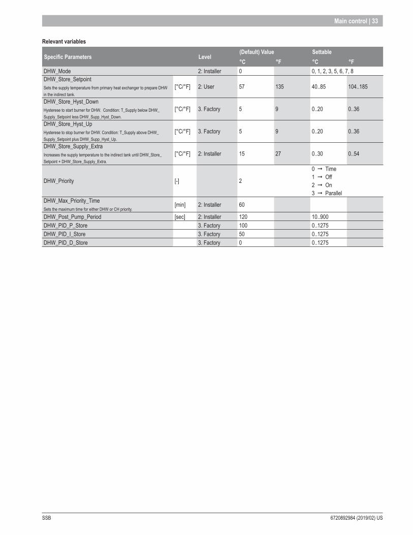
SSB 6720892984 (2019/02) US
Main control | 33
Relevant variables
Specific Parameters Level(Default) Value Settable°C °F °C °F
DHW_Mode 2: Installer 0 0, 1, 2, 3, 5, 6, 7, 8DHW_Store_Setpoint Sets the supply temperature from primary heat exchanger to prepare DHW in the indirect tank.
[°C/°F] 2: User 57 135 40..85 104..185
DHW_Store_Hyst_DownHysterese to start burner for DHW. Condition: T_Supply below DHW_Supply_Setpoint less DHW_Supp_Hyst_Down.
[°C/°F] 3. Factory 5 9 0..20 0..36
DHW_Store_Hyst_UpHysterese to stop burner for DHW. Condition: T_Supply above DHW_Supply_Setpoint plus DHW_Supp_Hyst_Up.
[°C/°F] 3. Factory 5 9 0..20 0..36
DHW_Store_Supply_Extra Increases the supply temperature to the indirect tank until DHW_Store_Setpoint + DHW_Store_Supply_Extra.
[°C/°F] 2: Installer 15 27 0..30 0..54
DHW_Priority [-] 2
0 ¨ Time1 ¨ Off2 ¨ On3 ¨ Parallel
DHW_Max_Priority_Time Sets the maximum time for either DHW or CH priority.
[min] 2: Installer 60
DHW_Post_Pump_Period [sec] 2: Installer 120 10..900DHW_PID_P_Store 3. Factory 100 0..1275DHW_PID_I_Store 3. Factory 50 0..1275DHW_PID_D_Store 3. Factory 0 0..1275
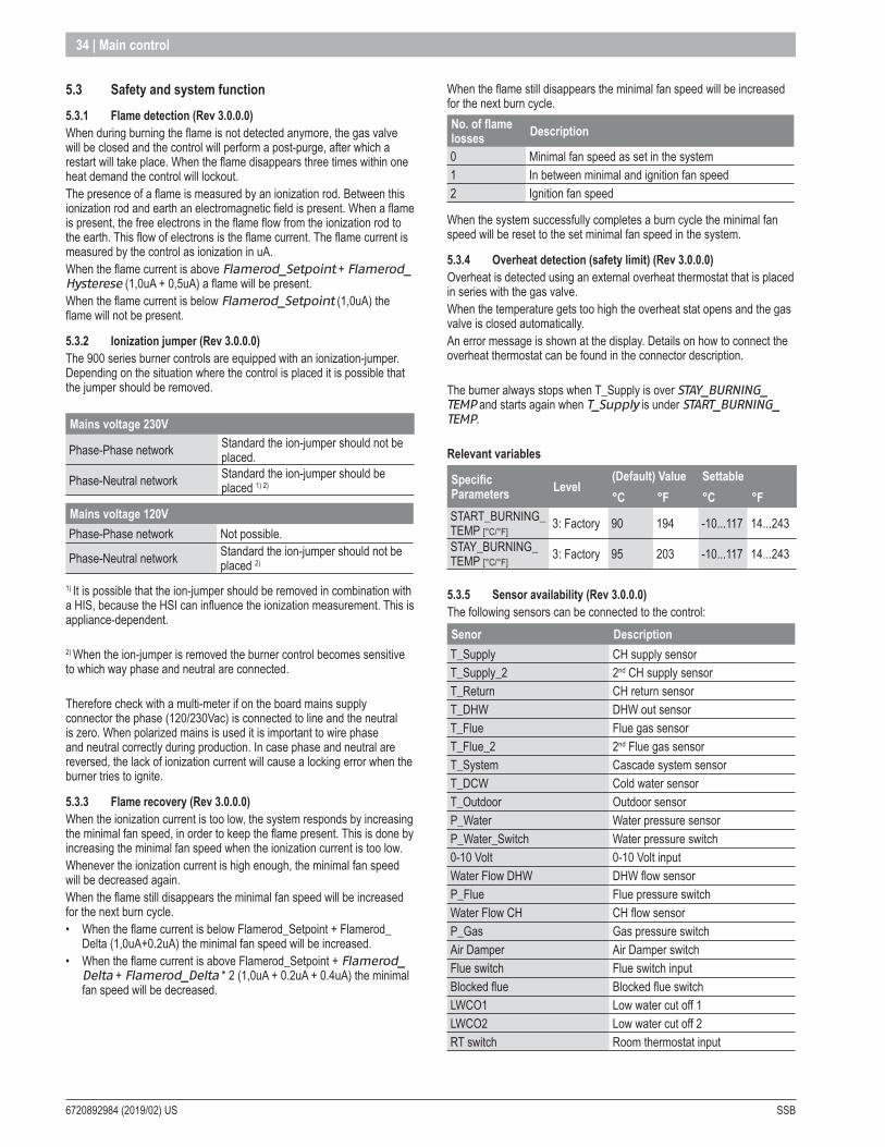
6720892984 (2019/02) US SSB
34 | Main control
5 .3 Safety and system function 5 .3 .1 Flame detection (Rev 3 .0 .0 .0) When during burning the flame is not detected anymore, the gas valve will be closed and the control will perform a post-purge, after which a restart will take place. When the flame disappears three times within one heat demand the control will lockout. The presence of a flame is measured by an ionization rod. Between this ionization rod and earth an electromagnetic field is present. When a flame is present, the free electrons in the flame flow from the ionization rod to the earth. This flow of electrons is the flame current. The flame current is measured by the control as ionization in uA. When the flame current is above Flamerod_Setpoint + Flamerod_Hysterese (1,0uA + 0,5uA) a flame will be present. When the flame current is below Flamerod_Setpoint (1,0uA) the flame will not be present.
5 .3 .2 Ionization jumper (Rev 3 .0 .0 .0)The 900 series burner controls are equipped with an ionization-jumper. Depending on the situation where the control is placed it is possible that the jumper should be removed. Mains voltage 230V
Phase-Phase network Standard the ion-jumper should not be placed.
Phase-Neutral network Standard the ion-jumper should be placed 1) 2)
Mains voltage 120VPhase-Phase network Not possible.
Phase-Neutral network Standard the ion-jumper should not be placed 2)
1) It is possible that the ion-jumper should be removed in combination with a HIS, because the HSI can influence the ionization measurement. This is appliance-dependent.
2) When the ion-jumper is removed the burner control becomes sensitive to which way phase and neutral are connected.
Therefore check with a multi-meter if on the board mains supply connector the phase (120/230Vac) is connected to line and the neutral is zero. When polarized mains is used it is important to wire phase and neutral correctly during production. In case phase and neutral are reversed, the lack of ionization current will cause a locking error when the burner tries to ignite.
5 .3 .3 Flame recovery (Rev 3 .0 .0 .0)When the ionization current is too low, the system responds by increasing the minimal fan speed, in order to keep the flame present. This is done by increasing the minimal fan speed when the ionization current is too low. Whenever the ionization current is high enough, the minimal fan speed will be decreased again. When the flame still disappears the minimal fan speed will be increased for the next burn cycle. • When the flame current is below Flamerod_Setpoint + Flamerod_
Delta (1,0uA+0.2uA) the minimal fan speed will be increased.• When the flame current is above Flamerod_Setpoint + Flamerod_
Delta + Flamerod_Delta * 2 (1,0uA + 0.2uA + 0.4uA) the minimal fan speed will be decreased.
When the flame still disappears the minimal fan speed will be increased for the next burn cycle.No. of flame losses Description
0 Minimal fan speed as set in the system1 In between minimal and ignition fan speed2 Ignition fan speed
When the system successfully completes a burn cycle the minimal fan speed will be reset to the set minimal fan speed in the system.
5 .3 .4 Overheat detection (safety limit) (Rev 3 .0 .0 .0)Overheat is detected using an external overheat thermostat that is placed in series with the gas valve. When the temperature gets too high the overheat stat opens and the gas valve is closed automatically. An error message is shown at the display. Details on how to connect the overheat thermostat can be found in the connector description.
The burner always stops when T_Supply is over STAY_BURNING_TEMP and starts again when T_Supply is under START_BURNING_TEMP.
Relevant variables
Specific Parameters Level
(Default) Value Settable°C °F °C °F
START_BURNING_TEMP [°C/°F]
3: Factory 90 194 -10...117 14...243
STAY_BURNING_TEMP [°C/°F]
3: Factory 95 203 -10...117 14...243
5 .3 .5 Sensor availability (Rev 3 .0 .0 .0)The following sensors can be connected to the control:Senor DescriptionT_Supply CH supply sensorT_Supply_2 2nd CH supply sensorT_Return CH return sensorT_DHW DHW out sensorT_Flue Flue gas sensorT_Flue_2 2nd Flue gas sensorT_System Cascade system sensorT_DCW Cold water sensorT_Outdoor Outdoor sensorP_Water Water pressure sensorP_Water_Switch Water pressure switch0-10 Volt 0-10 Volt inputWater Flow DHW DHW flow sensorP_Flue Flue pressure switchWater Flow CH CH flow sensorP_Gas Gas pressure switchAir Damper Air Damper switchFlue switch Flue switch inputBlocked flue Blocked flue switchLWCO1 Low water cut off 1LWCO2 Low water cut off 2RT switch Room thermostat input
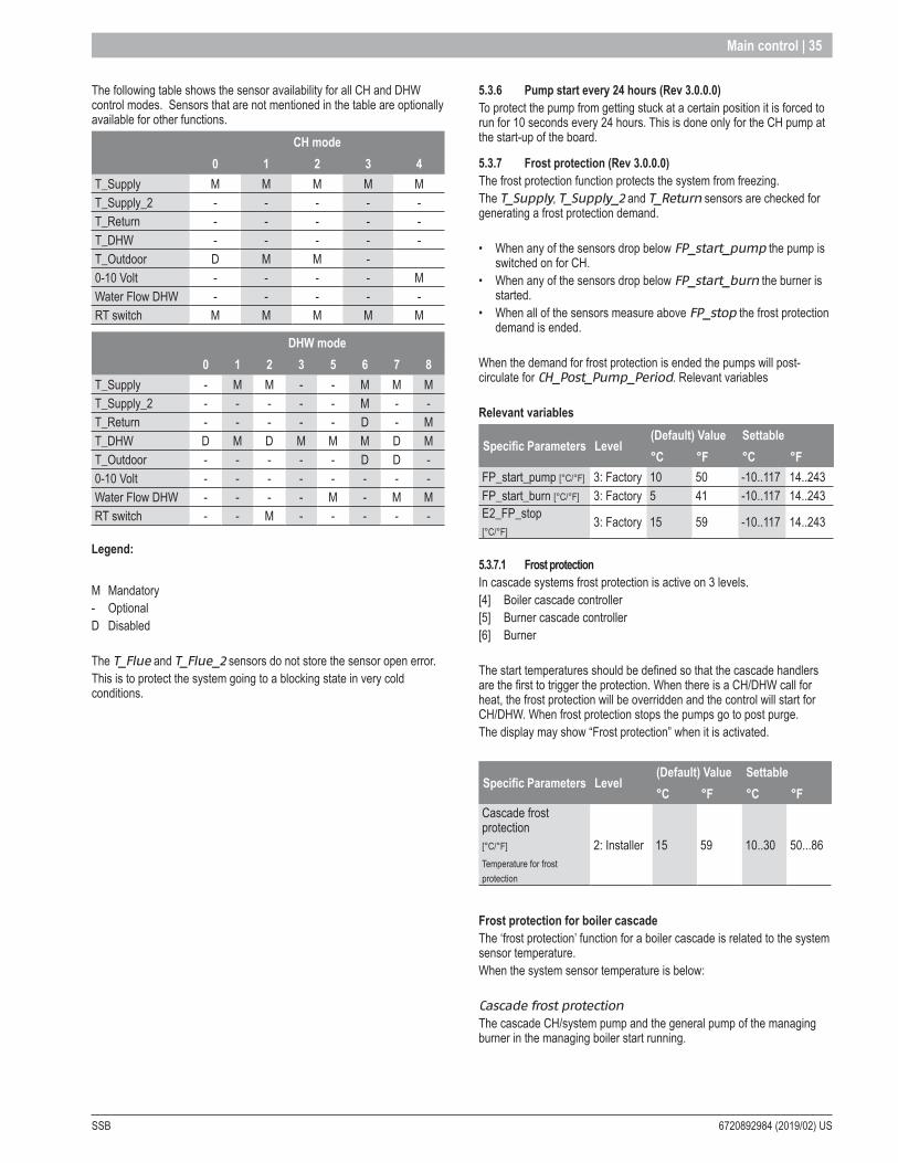
SSB 6720892984 (2019/02) US
Main control | 35
The following table shows the sensor availability for all CH and DHW control modes. Sensors that are not mentioned in the table are optionally available for other functions.
CH mode0 1 2 3 4
T_Supply M M M M MT_Supply_2 - - - - -T_Return - - - - -T_DHW - - - - -T_Outdoor D M M -0-10 Volt - - - - MWater Flow DHW - - - - -RT switch M M M M M
DHW mode0 1 2 3 5 6 7 8
T_Supply - M M - - M M MT_Supply_2 - - - - - M - -T_Return - - - - - D - MT_DHW D M D M M M D MT_Outdoor - - - - - D D -0-10 Volt - - - - - - - -Water Flow DHW - - - - M - M MRT switch - - M - - - - -
Legend:
M Mandatory- OptionalD Disabled
The T_Flue and T_Flue_2 sensors do not store the sensor open error. This is to protect the system going to a blocking state in very cold conditions.
5 .3 .6 Pump start every 24 hours (Rev 3 .0 .0 .0)To protect the pump from getting stuck at a certain position it is forced to run for 10 seconds every 24 hours. This is done only for the CH pump at the start-up of the board.
5 .3 .7 Frost protection (Rev 3 .0 .0 .0)The frost protection function protects the system from freezing. The T_Supply, T_Supply_2 and T_Return sensors are checked for generating a frost protection demand.
• When any of the sensors drop below FP_start_pump the pump is switched on for CH.
• When any of the sensors drop below FP_start_burn the burner is started.
• When all of the sensors measure above FP_stop the frost protection demand is ended.
When the demand for frost protection is ended the pumps will post-circulate for CH_Post_Pump_Period. Relevant variables
Relevant variables
Specific Parameters Level(Default) Value Settable°C °F °C °F
FP_start_pump [°C/°F] 3: Factory 10 50 -10..117 14..243FP_start_burn [°C/°F] 3: Factory 5 41 -10..117 14..243E2_FP_stop [°C/°F]
3: Factory 15 59 -10..117 14..243
5 .3 .7 .1 Frost protectionIn cascade systems frost protection is active on 3 levels. [4] Boiler cascade controller [5] Burner cascade controller [6] Burner
The start temperatures should be defined so that the cascade handlers are the first to trigger the protection. When there is a CH/DHW call for heat, the frost protection will be overridden and the control will start for CH/DHW. When frost protection stops the pumps go to post purge. The display may show “Frost protection” when it is activated.
Specific Parameters Level(Default) Value Settable°C °F °C °F
Cascade frost protection [°C/°F]
Temperature for frost protection
2: Installer 15 59 10..30 50...86
Frost protection for boiler cascade The ‘frost protection’ function for a boiler cascade is related to the system sensor temperature. When the system sensor temperature is below:
Cascade frost protectionThe cascade CH/system pump and the general pump of the managing burner in the managing boiler start running.

6720892984 (2019/02) US SSB
36 | Main control
Frost protection for boiler cascade The ‘frost protection’ function for a burner cascade is related to the boiler sensor temperatures. When the boiler sensor temperature or the managing burner supply/return temperature is below:
Cascade frost protection The cascade CH/system pump and the general pump of the managing burner start running.
Cascade frost protection – 5°CCascade heat demand is activated to open the optional air damper, the general pumps of all the burners will be started. Demand with setpoint Cascade frost protection allows the burners to start burning until the lowest of both boiler, managing supply and return temperatures are above Cascade frost protection + 5°C.
Frost protection on burner As last protection the controllers for the burners can force themselves to burn.
NOTE: On systems with an air damper this demand will not be served when the air damper is closed.
If the burner supply/return temperature drops below 5°C (41°F) the burner starts at minimum power and continues burning until the lowest of both supply and return temperatures are above 15°C (59°F).
Frost protection in cascades with air damperTo enable frost protection a demand must be generated on the cascade controller. This is covered by the frost protection and needed because the air damper must be opened by the cascade controller before a burner can start.
5 .3 .8 Flue temperature protection (Rev 3 .0 .0 .0)The flue temperature protection function protects against the flue gas reaching too high temperatures. Either a flue gas sensor or a flue switch can be used. • When the T_Flue or T_Flue_2 sensor measure above the Max_
Flue_Gas_Temp the control generates a Flue_Gas_Error.• When the Flue_Switch closes the control generates a Flue_Gas_
Error.
When the control is in a Flue_Gas_Error the fan will run at the minimum fan speed.
Burner power limitation When a flue gas sensor is connected the control will limit the burner power when the flue gas temperature reaches the set Max_Flue_Gas_Temp. The maximum burner power is linearly limited when the flue gas temperature is within Max_Flue_Gas_Temp – 5°C and Max_Flue_Gas_Temp.
Relevant variables
Specific Parameters Level
(Default) Value Settable
°C °F °C °FMax_Flue_Gas_Temp [°C/°F]
3: Factory 100 212 40...130 104...266
5 .3 .9 Input configuration 900MN (Rev 4.0.905.16712)There are several multiple function inputs that can be applied for different types of appliances. The function of the input can be selected via the epHS display but also with LabVision PC software.
The following input functions can be selected:
Input Description
J72-3
0 ¨ Disabled1 ¨ Water pressure sensor2 ¨ CH flow switch3 ¨ Flue pressure switch
J72-40 ¨ Disabled1 ¨ T_DCW sensor2 ¨ Water pressure switch
J77-8
0 ¨ Disabled1 ¨ DHW flow sensor2 ¨ DHW flow switch3 ¨ CH flow switch
J79-100 ¨ Disabled1 ¨ Drain switch2 ¨ Gas pressure switch
J123-6(*)0 ¨ T_Supply_2 sensor1 ¨ Disabled2 ¨ Air damper switch
J63-100 ¨ Disabled1 ¨ T_Return sensor2 ¨ Vapor switch
J64-110 ¨ Disabled1 ¨ T_DHW sensor2 ¨ T_Zone sensor
J65-12
0 ¨ Disabled1 ¨ T_Fluesensor2 ¨ Flueswitch3 ¨ APSswitch
676-13
0 ¨ Disabled1 ¨ T_Flue_2 sensor2 ¨ T_Flue_2 with blocked flue3 ¨ T_System sensor4 ¨ Blocked flue switch
(*) Duplex safety sensors cannot be adjusted freely.
5 .3 .10 Output configuration 900MN (Rev 4.0.905.16712) There are several multiple function outputs that can be applied for different types of appliances. The function of the output can be selected via the epHS display but also with LabVision PC software.
The following outputs are available on the control:Output Connection Type outputProg. Output 1 J3 3-8 Relay outputProg. Output 2 J3 5-10 Relay outputProg. Output 3 J3 6 Relay outputProg. Output 4 J3 1-2-7 Relay outputProg. Output 5 J3 4-9 Relay output

SSB 6720892984 (2019/02) US
Main control | 37
Relay output For the relay output the following output options are available:Output option 0 ¨ Disabled1 ¨ General pump2 ¨ CH pump3 ¨ DHW pump4 ¨ System pump5 ¨ Cascade pump6 ¨ Alarm relay7 ¨ Filling valve8 ¨ LPG tank9 ¨ External igniter10 ¨ Air-damper14 ¨ Zone pump15 ¨ Mixing valve open16 ¨ Mixing valve close
Triac output For the triac output the following output options are available:Output option 0 ¨ Disabled1 ¨ General pump10 ¨ Air-damper11 ¨ HSI12 ¨ Mod.Pump
3-Way valve outputThe 3-way valve output can be selected for CH pump/valve or DHW pump/valve. When selected for CH, the output is powered when there is a CH demand. When selected for DHW, the output is powered when there is a DHW demand.
5 .3 .11 Heat exchanger protection: max differential (Rev 3 .0 .0 .0)To avoid temperature differences that are too large in the primary heat exchanger, the burner load automatically decreases when the Return-Supply temperature differential increases too much.
At maximum burner power the ΔT Hx_Diff_DeltaT_Min is limited to 40°C (72°F) and at low burner power a ΔT above 48°C (86°F) (= Hx_Diff_DeltaT_Min +8°C) is allowed.
Above ΔT 52°C(94°F) (= Hx_Diff_DeltaT_Min +8°C + 5°C) the burner is switched OFF during Diff_Max_Wait_Time (settable).
In between 40°C (72°F) and 48°C (86°F) ΔT over the heat exchanger, the burner power is linear limited.
To achieve this the PID output value is linear limited between minimum (@48°C ΔT) and maximum (@40°C ΔT).However when the calculated PID output for temperature control is already below this limit, this output value remains the current control value.
Relevant variables
Specific Parameters Level(Default) Value Settable°C °F °C °F
HX Diff DeltaT Min [°C/°F]
3: Factory 40 72 10...80 18...144
HX Diff Max Wait Time [sec.]
3: Factory 0 1...255 sec.
5 .3 .12 Appliance selection (Rev 3 .0 .0 .0)The control is designed to store specific parameter sets of different boiler models. By defining specific setting for different appliance models the same control can be used for a complete product range. Depending on which model the control is applied to, it only will be necessary to change just one single parameter.
When this parameter is changed the following settings are changed: • Maximal fan speed• Minimal fan speed• Ignition speed(*)• Maximum flue gas temperature(*) Ignition speed is the same as Pre Purge Speed and Post Purge speed.The appliance can store 6 appliance type settings.
The following appliances are available (example):
ID Min . fan speed (rpm)
Ignition fan speed (rpm)
Max fan speed (rpm)
Max flue gas temp .
50 1500 3750 6000 95°C / 203°F51 1500 3750 6000 95°C / 203°F52 1500 3750 6000 95°C / 203°F53 1500 3750 6000 95°C / 203°F54 1500 3750 6000 95°C / 203°F55 1500 3750 6000 95°C / 203°F
Relevant variablesSpecific Parameters Level (Default) Value SettableAppliance type [-]Selection for the appliance type
2: Installer 50 50...55
5 .3 .13 Anti-legionella protection (Rev 3 .0 .0 .0)Anti-Legionella protection is enabled for DHW modes with an external tank with a sensor (DHW Mode 1).
To prevent legionella a special function is implemented in the software. • When DHW Mode 1 is selected the Anti-Legionella protection will be
checked on the T_DHW_Out sensor.This sensor will be named the Anti_Legionella_Sensor in the remaining part of the explanation.
At least once every 168 hours (7 days) the Anti_Legionella_Sensor must reach a temperature above Anti_Legionella_Setpoint for a time specified by Anti_Legionella_Burn_Time.
If 7 days have passed and these conditions are not met, the burner is forced to heat-up the system for Anti-Legionella. When the Anti_Legionella_Sensor temperature is below Anti_

6720892984 (2019/02) US SSB
38 | Main control
Legionella_Setpoint the control switches ON the pumps, when the Anti_Legionella_Sensor temperature is above Anti_Legionella_Setpoint + 5°C the control stops the pumps.
When DHW Mode 1 is selected the burner setpoint will be at Anti_Legionella_Setpoint + DHW_Store_Supply_Extra, for DHW Mode 6&7 the burner setpoint will be at Anti_Legionella_Setpoint.
If the supply temperature drops below the burner setpoint the burner is started as well.The burner is PID controlled towards the burner setpoint. When the supply temperature rises above burner setpoint + DHW_Supp_Hysterese_Up the burner is switched OFF.
When the Anti_Legionella_Sensor is above Anti_Legionella_Setpoint – 3°C for Anti_Legionella_Burn_Time the controller goes into post pumping and ends the Anti-Legionella demand. When the controller has powered up, the Anti_Legionella_Sensor temperature must reach a temperature of Anti_Legionella_Setpoint (for Anti_Legionella_Burn_Time) within 2 hours, otherwise the burner is forced into Anti-Legionella demand.
Every time an Anti-Legionella demand has ended the Anti_Legionella_Active_Counter is incremented to indicate how many Anti-Legionella actions have been performed. This counter can be found in the screen Boiler History in the epHS diagnostic tool LabVision. Also the Anti Legionella Wait Time is started to delay the next anti legionella cycle.
This diagnostic tool can also override the wait time for Anti-Legionella. When this demand is forced by LabVision, the timer will be set to 0 and Anti-Legionella demand will start immediately. Then the demand must be completed successfully before the wait timer is set again.
The anti-legionella demand has priority over any DHW and CH demand. However when the anti-legionella protection is active and there is no heat or burn demand because the Anti_Legionella_Sensor is already at a high enough temperature CH/DHW demand will be accepted as normal.
Relevant variables
Specific Parameters Level
(Default) Value Settable°C °F °C °F
Anti_Legionella_Setpoint Setpoint for Anti-Legionella demand
3: Factory 60 140 50...90 122...194
Anti_Legionella_Burn_Time [min]
3: Factory 30 5..120
Anti_Legionella_Wait_TimeWait time for Anti-Legionella demand
120 min after cold start, 168 hr after first successful Anti-Legionella demand
5 .3 .14 De-Air sequence (Rev 3.0.0.0)The De-Air sequence it is a safety function starting at every power ON and is used to remove the air from the heat-exchanger. The De-Air sequence does not start after a general reset (such as the locking error reset or 24 hour reset).
The display will show “dAir” indicating that the controller is performing the De-Air sequence to purge the heat exchanger of air, by sequencing the circulator OFF and ON. The user can cancel the De-Air sequence when he presses a specific key-button combination from the display.
By default “De-Air” sequence takes around 14 minutes. • 1st cycle: the 3 ways valve moves to CH position and the general
pump is activated for 10 seconds, deactivated for 10 seconds, activated again for 10 seconds and then deactivated again for 10 seconds (DAir_Repeation_OnOff, which means ON/OFF/ON/OFF each time for 10 seconds = 40 seconds in total).
• 2nd cycle: it starts when 1st cycle is ended. The 3 ways valve is moved to DHW position and repeats the same cycling of the pump (DAir_Repeation_OnOff, which means ON/OFF/ON/OFF each time for 10 seconds = 40 second in total).
This sequence (1st cycles + 2nd cycles) is performed DAir_Number_Cycles times (if DAir_Number_Cycles is 10 “de-air” sequence lasts (10 x 40) x 2 = 800 seconds).
During De-Air sequence no demand will be served.
When the water pressure is too low or pressure sensor is in error, the De-Air sequence will be suspended until water pressure / sensor pressure is stable again. In that case the De-Air sequence will last longer than the estimated 14 minutes.
The following scheme below shows the behaviour of the 3 way valve and general pump during one whole cycle of De-Air sequence with a DAir_Repeation_OnOff set to 2.

SSB 6720892984 (2019/02) US
Main control | 39
Relevant variablesSpecific Parameters Level (Default) Value RangeDe_Air_Config0 = DAir disabled;
1 = DAir enabled.
2: Installer 0 0..1
De_Air_StateCurrent state of the DAir function.
1: User - -
DAir_Repeation_OnOffNumber of repeating ON/OFF.
2: Installer2 0..255
DAir_Number_CyclesNumber of DAir cycles..
2: Installer 10 0..255
5 .3 .15 Low water cut off (Rev 3 .0 .0 .0)A Low Water Cut Off (LWCO) sensor can be enabled to detect if there is enough water in the boiler. When this is not the case a non-volatile lockout error is generated.
Relevant variablesSpecific Parameters Level (Default)Value RangeProgrammable input LWCO 1 3: Factory 0 0 ¨ Disabled
1 ¨ EnabledProgrammable input LWCO 2 3: Factory 0 0 ¨ Disabled
1 ¨ Enabled
5 .3 .16 Heat exchanger protection (Rev 3 .0 .0 .0)Heat Exchanger Protection limits the max. heat load based on the heat exchanger flow (CH flow).
To avoid temperature differences that are too large in the primary heat exchanger, the burner load automatically decreases when the CH water flow decreases too much. • Above Nominal_EX_Flow_Rate the maximum burner power is
available.• At Min_EX_Flow_Rate the minimum burner power is available.• Below Min_EX_Flow_Rate the burner is stopped.
In between Nominal_EX_Flow_Rate and Min_EX_Flow_Rate, the burner power is linear limited. To achieve this the PID output value is linear limited between Nominal_EX_Flow_Rate and Min_EX_Flow_Rate. However, when the calculated PID output for temperature control is already below this limit, this output value remains the current control value. The power limitation will be performed only in Burn status. Consequentially in Pre-Purge status the fan power is always @ 50% of maximum power available.
When a demand request is present the level of the flow is evaluated. If the flow is too low (smaller than the Min_EX_Flow_Rate parameter) and stays low for at least (PRE_PURGE_TIME - 2 seconds), a warning is raised (LOWEXFLOW_PROTECTION warning). Although the timeout is limited between a minimum value of 4 seconds and a maximum value of 60 seconds.
In case the flow level is too low the fan will be switched OFF in order to protect the heat exchanger while the pump stays On. When the level of the flow will be again stable for at least 20 seconds the warning status is cleared and the burner will go again in BURN status if a request is still pending. In case the request of demand has been cancelled the burner will go in STANDBY.
Max. available power (%)
Min. Flow Nominal Flow
Max. (100%)
Min
Flow (m3/h)
0%
Based on the value of the Nominal_Flow parameter there are two case of low flow protection behaviour.
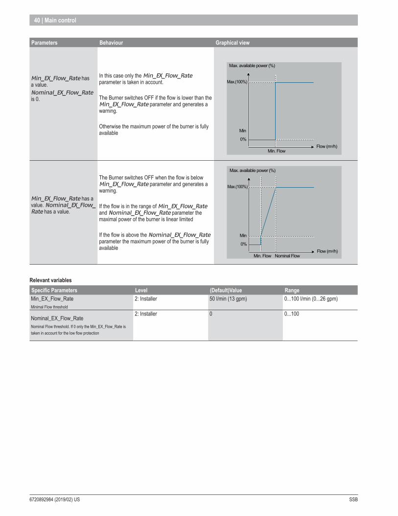
6720892984 (2019/02) US SSB
40 | Main control
Parameters Behaviour Graphical view
Min_EX_Flow_Rate has a value. Nominal_EX_Flow_Rate is 0.
In this case only the Min_EX_Flow_Rate parameter is taken in account.
The Burner switches OFF if the flow is lower than the Min_EX_Flow_Rate parameter and generates a warning.
Otherwise the maximum power of the burner is fully available
Max. available power (%)
Min. Flow
Max.(100%)
Min
Flow (m3/h)0%
Min_EX_Flow_Rate has a value. Nominal_EX_Flow_Rate has a value.
The Burner switches OFF when the flow is below Min_EX_Flow_Rate parameter and generates a warning.
If the flow is in the range of Min_EX_Flow_Rate and Nominal_EX_Flow_Rate parameter the maximal power of the burner is linear limited
If the flow is above the Nominal_EX_Flow_Rate parameter the maximum power of the burner is fully available
Max. available power (%)
Min. Flow Nominal Flow
Max.(100%)
Min
Flow (m3/h)0%
Relevant variablesSpecific Parameters Level (Default)Value RangeMin_EX_Flow_RateMinimal Flow threshold
2: Installer 50 l/min (13 gpm) 0...100 l/min (0...26 gpm)
Nominal_EX_Flow_RateNominal Flow threshold. If 0 only the Min_EX_Flow_Rate is taken in account for the low flow protection
2: Installer 0 0...100
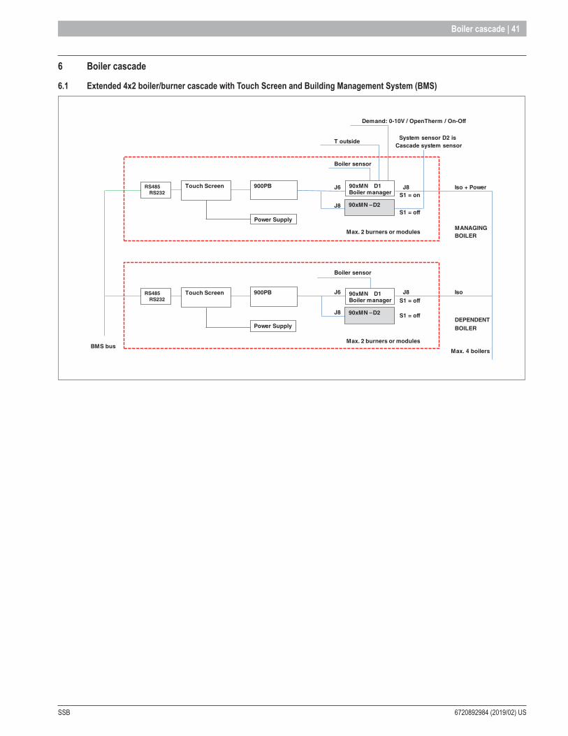
SSB 6720892984 (2019/02) US
Boiler cascade | 41
6 Boiler cascade
6 .1 Extended 4x2 boiler/burner cascade with Touch Screen and Building Management System (BMS)
Demand: 0-10V / OpenTherm / On-Off
T outsideSystem sensor D2 is
Cascade system sensor
Boiler sensor
J6 J8 Iso + Power S1 = on
J8 S1 = off
MANAGINGBOILER
Boiler sensor
J6 J8 Iso S1 = off
J8DEPENDENT
BMS bus
S1 = off
BOILER
Max. 4 boilers
90xMN -900PBTouch Screen
Power Supply
Max. 2 burners or modules
90xMN –
––
D2
900PB
Max. 2 burners or modules
RS485RS232
Power Supply
Touch ScreenRS485RS232
90xMN D1Boiler manager
90xMN –
––
D2
90xMN D1Boiler manager
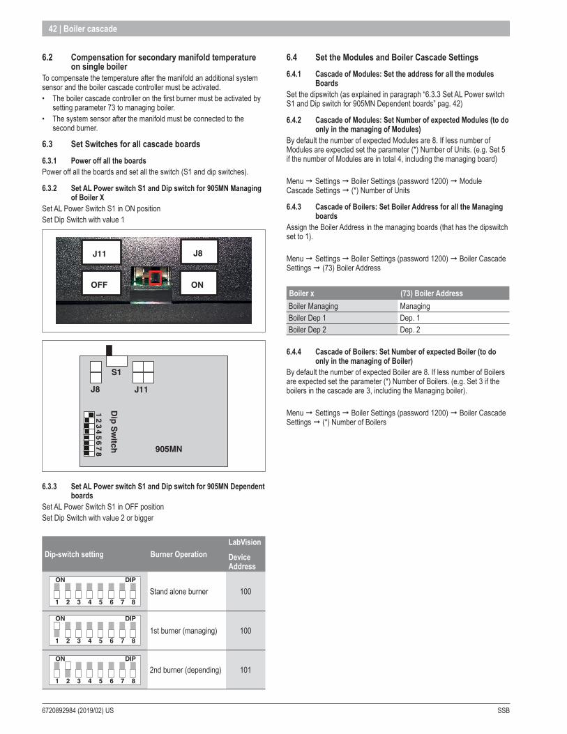
6720892984 (2019/02) US SSB
42 | Boiler cascade
6 .2 Compensation for secondary manifold temperature on single boiler
To compensate the temperature after the manifold an additional system sensor and the boiler cascade controller must be activated.• The boiler cascade controller on the first burner must be activated by
setting parameter 73 to managing boiler.• The system sensor after the manifold must be connected to the
second burner.
6 .3 Set Switches for all cascade boards6 .3 .1 Power off all the boardsPower off all the boards and set all the switch (S1 and dip switches).
6 .3 .2 Set AL Power switch S1 and Dip switch for 905MN Managing of Boiler X
Set AL Power Switch S1 in ON position Set Dip Switch with value 1
ONOFF
J8J11
J8 J11
905MN
S1
Dip
Sw
itch
12
34
56
78
6 .3 .3 Set AL Power switch S1 and Dip switch for 905MN Dependent boards
Set AL Power Switch S1 in OFF position Set Dip Switch with value 2 or bigger
Dip-switch setting Burner OperationLabVision
Device Address
1
ON DIP
2 3 4 5 6 7 8
1
ON DIP
2 3 4 5 6 7 8
1
ON DIP
2 3 4 5 6 7 8
1
ON DIP
2 3 4 5 6 7 8
1
ON DIP
2 3 4 5 6 7 8
1
ON DIP
2 3 4 5 6 7 8
1
ON DIP
2 3 4 5 6 7 8
1
ON DIP
2 3 4 5 6 7 8
1
ON DIP
2 3 4 5 6 7 8
Stand alone burner 1001
ON DIP
2 3 4 5 6 7 8
1
ON DIP
2 3 4 5 6 7 8
1
ON DIP
2 3 4 5 6 7 8
1
ON DIP
2 3 4 5 6 7 8
1
ON DIP
2 3 4 5 6 7 8
1
ON DIP
2 3 4 5 6 7 8
1
ON DIP
2 3 4 5 6 7 8
1
ON DIP
2 3 4 5 6 7 8
1
ON DIP
2 3 4 5 6 7 8
1st burner (managing) 100
1
ON DIP
2 3 4 5 6 7 8
1
ON DIP
2 3 4 5 6 7 8
1
ON DIP
2 3 4 5 6 7 8
1
ON DIP
2 3 4 5 6 7 8
1
ON DIP
2 3 4 5 6 7 8
1
ON DIP
2 3 4 5 6 7 8
1
ON DIP
2 3 4 5 6 7 8
1
ON DIP
2 3 4 5 6 7 8
1
ON DIP
2 3 4 5 6 7 8
2nd burner (depending) 101
6 .4 Set the Modules and Boiler Cascade Settings 6 .4 .1 Cascade of Modules: Set the address for all the modules
Boards Set the dipswitch (as explained in paragraph “6.3.3 Set AL Power switch S1 and Dip switch for 905MN Dependent boards” pag. 42)
6 .4 .2 Cascade of Modules: Set Number of expected Modules (to do only in the managing of Modules)
By default the number of expected Modules are 8. If less number of Modules are expected set the parameter (*) Number of Units. (e.g. Set 5 if the number of Modules are in total 4, including the managing board)
Menu ¨ Settings ¨ Boiler Settings (password 1200) ¨ Module Cascade Settings ¨ (*) Number of Units
6 .4 .3 Cascade of Boilers: Set Boiler Address for all the Managing boards
Assign the Boiler Address in the managing boards (that has the dipswitch set to 1).
Menu ¨ Settings ¨ Boiler Settings (password 1200) ¨ Boiler Cascade Settings ¨ (73) Boiler Address
Boiler x (73) Boiler AddressBoiler Managing ManagingBoiler Dep 1 Dep. 1Boiler Dep 2 Dep. 2
6 .4 .4 Cascade of Boilers: Set Number of expected Boiler (to do only in the managing of Boiler)
By default the number of expected Boiler are 8. If less number of Boilers are expected set the parameter (*) Number of Boilers. (e.g. Set 3 if the boilers in the cascade are 3, including the Managing boiler).
Menu ¨ Settings ¨ Boiler Settings (password 1200) ¨ Boiler Cascade Settings ¨ (*) Number of Boilers
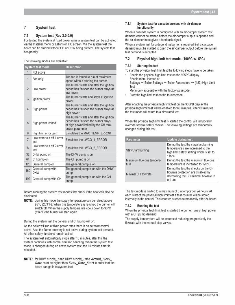
SSB 6720892984 (2019/02) US
System test | 43
7 System test
7 .1 System test (Rev 3 .0 .0 .0)For testing the system at fixed power rates a system test can be activated via the Installer menu or LabVision PC screen. Via the system test the boiler can be started without CH or DHW being present. The system test has priority.
The following modes are available: System test mode Description
1 Not active
1 Fan only The fan is forced to run at maximum speed without starting the burner.
2 Low powerThe burner starts and after the ignition period has finished the burner stays at low power
3 Ignition power The burner starts and stays at ignition power
4 High powerThe burner starts and after the ignition period has finished the burner stays at high power
5 High power limitedThe burner starts and after the ignition period has finished the burner stays at high power limited by the CH max. power parameter
6 High limit error test Simulates the MAX_TEMP_ERROR
7 Low water cut off 1 error test Simulates the LWCO_1_ERROR
8 Low water cut off 2 error test Simulates the LWCO_2_ERROR
32 DHW pump on The DHW pump is on64 CH pump on The CH pump is on128 General pump on The general pump is on
160 General pump with DHW
The general pump is on with the DHW pump
192 General pump with CH The general pump is on with the CH pump
Before running the system test modes first check if the heat can also be dissipated. NOTE: during this mode the supply temperature can be raised above
95°C (203°F). When this temperature is reached the burner will switch off. When the supply temperature cools down to 90°C (194°F) the burner will start again.
During the system test the general and CH pump will on. As the boiler will run at fixed power rates there is no setpoint control active. Also the flame recovery is not active during system test demand. All other safety functions remain active.The system test automatically stops after 10 minutes, after this the system continues with normal demand handling. When the system test mode is changed during an active system test, the 10 minute timer is reloaded.
NOTE: for DHW Mode_7 and DHW Mode_8 the Actual_Flow_Rate must be higher than Flow_Rate_Start in order that the board can go in to system test.
7 .1 .1 System test for cascade burners with air-damper functionality
When a cascade system is configured with an air-damper system test demand cannot be started before the air-damper output is opened and the air-damper input gives a feedback signal. When a system test for a depending burner is required first a cascade demand must be started to open the air-damper output before the system test demand is accepted.
7 .2 Physical high limit test mode . (100°C +/- 5°C)7 .2 .1 Starting the test To start the physical high limit test the following steps have to be taken.• Enable the physical high limit test on the 905PB display.
Enable menu located at: Settings ¨ Boiler Settings ¨ Boiler Parameters ¨ (183) High Limit Test Menu only accessible with the factory passcode.
• Start the high limit test on the touchscreen.
After enabling the physical high limit test on the 905PB display the physical high limit test will be enabled for 60 minutes. After 60 minutes the test mode will return to a simulated test.
When the physical high limit test is started the control will temporarily override several safety checks. The following settings are temporarily changed during this test.
Parameter Update during test .
Stay/Start burning During the test the stay/start burning temperatures are increased to the high limit safety setting which is set to 115°C
Maximum flue gas tempera-ture
During the test the maximum flue gas temperature is increased to 120°C.
Minimal CH flowrate During the test the checks on the CH flowrate protection are disabled by decreasing the CH minimal flowrate to 0.0 l/m.
The test mode is limited to a maximum of 5 attempts per 24 hours. At each start of the physical high limit test a test counter will be stored internally in the control. This counter is reset automatically after 24 hours.
7 .2 .2 Running the testWhen the physical high limit test is started the burner runs at high power with a CH pump demand. The supply temperature will be increased reducing progressively the flowrate with the manual stop valves.
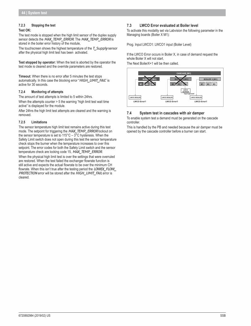
6720892984 (2019/02) US SSB
44 | System test
7 .2 .3 Stopping the testTest OK: The test mode is stopped when the high limit sensor of the duplex supply sensor detects the MAX_TEMP_ERROR. The MAX_TEMP_ERROR is stored in the boiler error history of the module, The touchscreen shows the highest temperature of the T_Supply sensor after the physical high limit test has been activated.
Test stopped by operator: When the test is aborted by the operator the test mode is cleared and the override parameters are restored.
Timeout: When there is no error after 5 minutes the test stops automatically. In this case the blocking error “HIGH_LIMIT_FAIL” is active for 30 seconds.
7 .2 .4 Monitoring of attemptsThe amount of test attempts is limited to 5 within 24hrs. When the attempts counter > 5 the warning “high limit test wait time active” is displayed for the module. After 24hrs the high limit test attempts are cleared and the warning is removed.
7 .2 .5 LimitationsThe sensor temperature high limit test remains active during this test mode. The setpoint for triggering the MAX_TEMP_ERROR lockout on the sensor temperature is set to 115°C – 3°C hysteresis. When the Safety Limit switch does not open during this test the sensor temperature check stops the burner when the temperature increases to over this setpoint. The error codes for both the Safety Limit switch and the sensor temperature check are locking code 15, MAX_TEMP_ERROR.When the physical high limit test is over the settings that were overruled are restored. When the test failed the exchanger flowrate function is still active and expects the actual flowrate to be over the minimum CH flowrate. When this isn’t true after the testing period the LOWEX_FLOW_PROTECTION error will be stored after the HIGH_LIMIT_FAIL error is cleared.
7 .3 LWCO Error evaluated at Boiler levelTo activate this modality set via Labvision the following parameter in the Managing boards (Boiler X M1):
Prog. Input LWCO1: LWCO1 input (Boiler Level)
If the LWCO Error occurs in Boiler X, in case of demand request the whole Boiler X will not start.The Next BoilerX+1 will be then called.
M1
LWCO Error!!
LWCO BOILER
M2 M3
BOILER 1 [M1]
CASCADE [M1]
M1
LWCO Error!!
LWCO BOILER
M2 M3
BOILER 2 [M1]
M1
LWCO Error!!
Input ignored!
LWCO BOILER
LWCO BURNER
M2 M3
BOILER 3 [M1]
7 .4 System test in cascades with air damper To enable system test a demand must be generated on the cascade controller. This is handled by the PB and needed because the air damper must be opened by the cascade controller before a burner can start.
SSB 6720892984 (2019/02) US
Service reminder | 45
8 Service reminder
8 .1 Service ReminderThe Service Reminder functionality is available on all, except the 900PB00 PCB configuration.This functionality requires the large EEPROM therefore it will not be available on the 900PB00 PCB configuration.
8 .1 .1 Service ReminderThe Service Reminder will remind the owner/user of the appliance to service the appliance at a specified Service_Interval (factory setting). When service is not done within the specified time, a service reminder will be shown on the screen, alternating with the normal status display. The Service_Interval can be set as the number of burn hours or the number of operational (appliance is powered) hours. This can be done by setting the Service_Hour_Counter (factory) parameter.
8 .1 .2 Service Overdue loggingWhen the service reminder has become active, the time it takes before service is actually done is being logged by the 900PB (in hours). This time is called the Service Overdue time. With this log the factory can read back how long service was overdue on the system/appliance which can be useful when handling warranty claims. A maximum of 15 Service moments can be logged by the 900PB, when the log is full it will overwrite the oldest log entry. Each time the Service Reminder is being reset, a new service moment is counted and the Service Overdue counter will be stored in the log/history.
8 .1 .3 Service Reminder implementationsThere are two types of service reminders: (Normal) Service Reminder and Service Shutdown.
Service Reminder The (normal) Service Reminder will only show the service reminder message on the screen and will log how many time the ser-vice is overdue, and the appliance will remain fully operational.
Service Shutdown The Service Shutdown has the same functionality as the Service Reminder but will shut-down the appliance after the specified Service_Shutdown_Period (factory setting) after the service reminder became active (message is displayed). The appliance will shut-down and no demands are handled anymore. This way the owner/user has a warning before the appliance will actually shutdown. Shutting down the appliance is stored in the burner (main) control so disconnecting the display will not enable the appliance. Re-enabling the appliance is only possible by resetting the Service Reminder (Shutdown) which is done by the installer.
NOTE: The Service Shutdown is only available for 850 Platform products systems and is not supported for 900 Platform products (yet).
8 .1 .4 Resetting the Service ReminderThe Service Reminder (or Shutdown) can be reset by the installer that services the appliance. When the Service Reminder is being reset, a service moment will be counted and the Service Overdue counter will be stored in the log/history. It is possible to reset the Service Reminder counters before the Service Reminder was actually set.This should be done when the appliance was serviced before the Service Reminder was active. This will mean an overdue coun-ter of 0 hours will be stored on the log (which makes sense because the service was not overdue, but ahead of schedule).
8 .1 .5 Menu’s and ParametersService Reminder status information can be viewed from the Information menu. Here the installer can also reset the service reminder (accessible by any user-level).
(Sub) Menu item Description
Service History
View the service history (log). For each service moment the service overdue counter is stored. When the overdue counter is 0 hrs, this means service was done before the service reminder was active.The log is ordered so the most recent service moment is shown first (on top of the list).
Hours since last service / Burn hours since last service
Shows the number of hours (or burn hours) since the last service moment. Depends on the Service_Hour_Counter setting (burn or normal hours).
Hours till service / Burn hours till service / Hours till shutdown
Shows the number of hours (or burn hours) until service is required. Depends on the Service_Hour_Counter setting (burn or normal hours).When the Service Shutdown function is enabled and the Service Reminder is active, the number of hours until the appliance is shut-down will be shown.
Reset Service Reminder
Reset the Service Reminder (and store service overdue counter in the service history). Installer must first enter the installer password before the service reminder can be reset.
The Service Reminder parameters can be set from the Boiler Settings menu (Service submenu) when logged in as factory user-level.(Sub) Menu item Description
Service Hour Counter
Select how the hours until service must be counted. As burner hours or normal (appliance is powered) hours.
Service Interval
Number of hours after the Service Reminder must be shown. When disabled the (entire) Service Reminder functionality will be disabled.
Service Shutdown Period
Number of hours after the appliance must be shut-down when the Service Reminder became active. Time that the appliance is allowed to function with the service reminder active. When disabled, Service Shutdown function is disabled and the appliance will not be shut-down.
Reset Service Reminder
Reset the Service Reminder (and store service overdue counter in the service history).
Clear Service History
Clears the entire service history (number of service moments and the overdue counters).
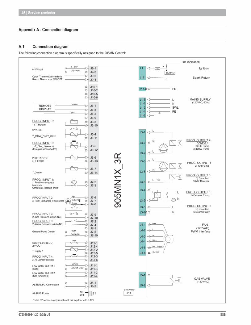
6720892984 (2019/02) US SSB
46 | Service reminder
Appendix A - Connection diagram
A .1 Connection diagramThe following connection diagram is specifically assigned to the 905MN Control:
GAS VALVE(120VrAC)
905M
N1X
_3R
NL
J2 1-6 PE
J5-1
J5-2
J9-1J9-3J9-2J9-4
Open Thermostat interface Room Thermostat ON/OFF
or
+5V
3) Heat_Exchanger_Flow sensor 0V(GND)
PROG. INPUT 1:
24V
PWM0V(GND)
General Pump Control
T_DHW_Out/T_Store
1) T_Return
MAINS SUPPLY (120VAC, 60Hz)
PE
Safety Limit (ECO)24VDC
J12-3J12-6
J12-2J12-5
J12-4J12-1
J6-5J6-12
J6-6J6-13
J6-4J6-11
J6-2J6-9J6-3J6-10
J6-1J6-8
J6-7J6-14
J14DIPSWITCH
0...10V
0V(GND)
J7-7J7-8
J7-1
J7-2
J7-6
J7-5J7-10
J7-9J7-10
J7-3
J7-2J7-4
T1
J17
1) T_Flue_1 (sensor) (Flue gas sensor/switch)
J10-1J10-2J10-5J10-6
J11-2J11-4
J11-1J11-3
J8-1J8-2
SWLJ1-1J1-5
J1-4J1-2
PROG. OUTPUT 4:CONFIG 1:
2) CH Pump3) DHW Pump
PROG. OUTPUT 1 2) CH Pump
PROG. OUTPUT 5: 1) General Pump
LN
L
L
N
N
J3-4
J3-9
J3-3
J3-8
J3-1
J3-7
J3-5
J3-10
J3-2
REMOTEDISPLAY
AL-BUS/PC Connection
PROG INPUT 2:
J3-6
J1-8
PROG. OUTPUT 2
6) Alarm Relay0) Disabled
1) Extra 5V sensor supply is optional, not together with 0-10V
PROG. INPUT 5:
PROG. INPUT 6:
Low Water Cut Off 1 (Safe)
COMM.
Low Water Cut Off 2 (Not functional)
LWCO1
LWCO1 GND
Spark Return
IgnitionBURNER
1K
Int. ionization
PROG. OUTPUT 3: 0) Disabled
10) Air Damper
2) Gas Pressure switch (NC)PROG INPUT 3:
2) Water Pressure switch (NC)PROG INPUT 8:
PROG INPUT 4:
N
L
HALL
OV GND
FAN(120VAC)
PWM interface
HALL Supply
J4-3J4-4
J4-2
J4-6
J4-5
J4-1L
N
L
S1ONOFFAL-BUS Power
L
N
L
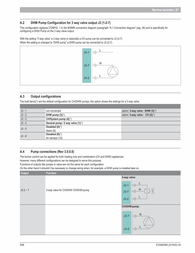
SSB 6720892984 (2019/02) US
Service reminder | 47
A .2 DHW Pump Configuration for 3 way valve output J3 (1-2-7)This configuration replaces CONFIG. 1 in the 905MN connection diagram (paragraph “A.1 Connection diagram” pag. 46) and is specifically for configuring a DHW Pump on the 3 way valve output.
With the setting “3 way valve” a 3 way valve or optionally a CH pump can be connected to J3 (2-7). When the setting is changed to “DHW pump” a DHW pump can be connected to J3 (2-7).
J3-1
J3-7
J3-2
L
N
L
A .3 Output configurationsThe bold items(*) are the default configuration for CH/DHW pumps, the option shows the settings for a 3 way valve.
J3 - 1 not connected option: 3-way valve - DHW (3)(*)J3 - 2 DHW pump (3)(*) option: 3-way valve - CH (2)(*)J3 - 3 CH/System pump (4)(*)J3 - 4 General pump / 2 way valve (1)(*)
J3 - 5 Disabled (0)(*)Alarm (6)
J3 - 6 Disabled (0)(*)Air damper (10)
A .4 Pump connections (Rev 3 .0 .0 .0)The burner control can be applied for both heating only and combination (CH and DHW) appliances.However, many different configurations can be designed to serve this purpose.Functions of outputs like pumps or valve are not the same for each configuration.On the other hand it shouldn’t be necessary to change wiring when, for example, a DHW pump is installed later on.Output Function
J3 2 – 7 3-way valve for CH/DHW CH/DHW-pump
3-way valve:
J3-1
J3-7
J3-2
L
N
L
CH/DHW-pump:
J3-7
J3-2
N
L

6720892984 (2019/02) US SSB
48 | Service reminder
Output Function
J3 3 – 8 Programmable output 1*
J3-3
J3-8
L
N
* For programmable output options see paragraph “5.3.10 Output configuration 900MN (Rev 4.0.905.16712)” pag. 36.
Output Function
J3 4 – 9 General pump
J3-4
J3-9 N
L
Output Function
J7 5 – 10 PWM pump out* PWM0V(GND)
J7-5J7-10
*Only available for the general pump.
Appendix B - Maximum load on outputs
B .1 Maximum load on outputs (for hardware up to 905MN1x_3Re)The mains fuse on 905MN is rated at 5AT, but to guarantee reliable operation with enough margin for power fluctuations, the maximum current through all outputs together must always stay below 4A.Following are two examples of combinations of devices that can be connected:
Device Max Current Max PowerControl and gas valve 0,5 A 60 VAGeneral Pump 2,0 A 240 VAOther Pump Do not connect! ¨ Power externallyFan 1,5 A 180 VATotal external load 4 A 480 VA
Device Max Current Max PowerControl and gas valve 0,5 A 60 VAGeneral Pump 1,0 A 120 VAOther Pump 1,0 A 120 VAFan 1,5 A 180 VATotal external load 4 A 480 VA
All other devices must be powered externally
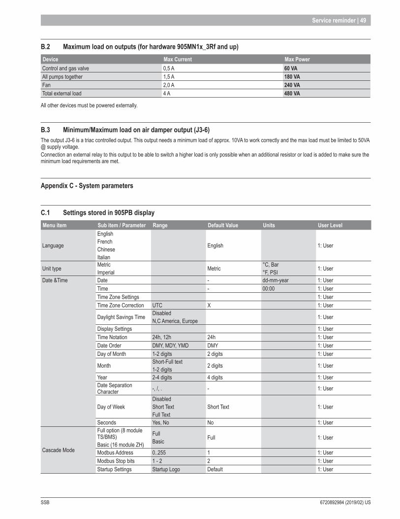
SSB 6720892984 (2019/02) US
Service reminder | 49
B .2 Maximum load on outputs (for hardware 905MN1x_3Rf and up)Device Max Current Max PowerControl and gas valve 0,5 A 60 VAAll pumps together 1,5 A 180 VAFan 2,0 A 240 VATotal external load 4 A 480 VA
All other devices must be powered externally.
B .3 Minimum/Maximum load on air damper output (J3-6)The output J3-6 is a triac controlled output. This output needs a minimum load of approx. 10VA to work correctly and the max load must be limited to 50VA @ supply voltage.Connection an external relay to this output to be able to switch a higher load is only possible when an additional resistor or load is added to make sure the minimum load requirements are met.
Appendix C - System parameters
C .1 Settings stored in 905PB displayMenu item Sub item / Parameter Range Default Value Units User Level
Language
English French Chinese Italian
English 1: User
Unit type MetricImperial Metric °C, Bar
°F, PSI 1: User
Date &Time Date - dd-mm-year 1: UserTime - 00:00 1: UserTime Zone Settings 1: UserTime Zone Correction UTC X 1: User
Daylight Savings Time DisabledN,C America, Europe 1: User
Display Settings 1: UserTime Notation 24h, 12h 24h 1: UserDate Order DMY, MDY, YMD DMY 1: UserDay of Month 1-2 digits 2 digits 1: User
Month Short-Full text1-2 digits 2 digits 1: User
Year 2-4 digits 4 digits 1: UserDate Separation Character -, /, . - 1: User
Day of WeekDisabledShort TextFull Text
Short Text 1: User
Seconds Yes, No No 1: User
Cascade Mode
Full option (8 module TS/BMS)Basic (16 module ZH)
FullBasic Full 1: User
Modbus Address 0..255 1 1: UserModbus Stop bits 1 - 2 2 1: UserStartup Settings Startup Logo Default 1: User
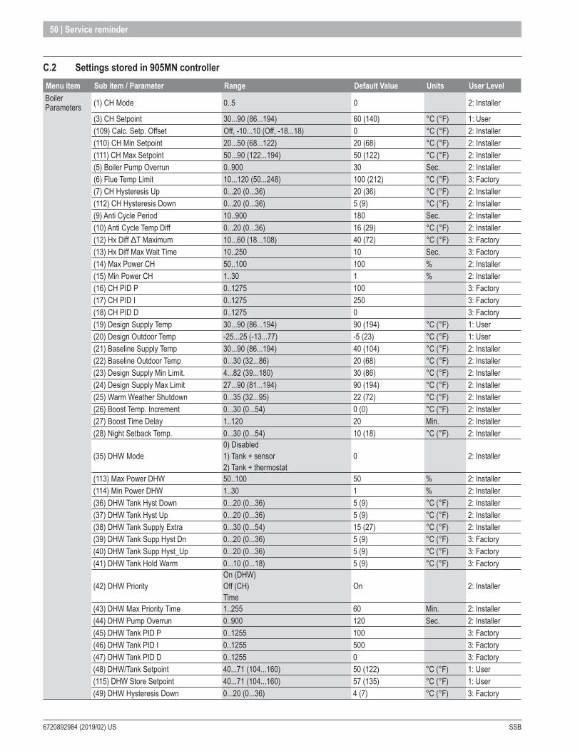
6720892984 (2019/02) US SSB
50 | Service reminder
C .2 Settings stored in 905MN controllerMenu item Sub item / Parameter Range Default Value Units User LevelBoiler Parameters (1) CH Mode 0..5 0 2: Installer
(3) CH Setpoint 30...90 (86...194) 60 (140) °C (°F) 1: User(109) Calc. Setp. Offset Off, -10...10 (Off, -18...18) 0 °C (°F) 2: Installer(110) CH Min Setpoint 20...50 (68...122) 20 (68) °C (°F) 2: Installer(111) CH Max Setpoint 50...90 (122...194) 50 (122) °C (°F) 2: Installer(5) Boiler Pump Overrun 0..900 30 Sec. 2: Installer(6) Flue Temp Limit 10...120 (50...248) 100 (212) °C (°F) 3: Factory(7) CH Hysteresis Up 0...20 (0...36) 20 (36) °C (°F) 2: Installer(112) CH Hysteresis Down 0...20 (0...36) 5 (9) °C (°F) 2: Installer(9) Anti Cycle Period 10..900 180 Sec. 2: Installer(10) Anti Cycle Temp Diff 0...20 (0...36) 16 (29) °C (°F) 2: Installer(12) Hx Diff ΔT Maximum 10...60 (18...108) 40 (72) °C (°F) 3: Factory(13) Hx Diff Max Wait Time 10..250 10 Sec. 3: Factory(14) Max Power CH 50..100 100 % 2: Installer(15) Min Power CH 1..30 1 % 2: Installer(16) CH PID P 0..1275 100 3: Factory(17) CH PID I 0..1275 250 3: Factory(18) CH PID D 0..1275 0 3: Factory(19) Design Supply Temp 30...90 (86...194) 90 (194) °C (°F) 1: User(20) Design Outdoor Temp -25...25 (-13...77) -5 (23) °C (°F) 1: User(21) Baseline Supply Temp 30...90 (86...194) 40 (104) °C (°F) 2: Installer(22) Baseline Outdoor Temp 0...30 (32...86) 20 (68) °C (°F) 2: Installer(23) Design Supply Min Limit. 4...82 (39...180) 30 (86) °C (°F) 2: Installer(24) Design Supply Max Limit 27...90 (81...194) 90 (194) °C (°F) 2: Installer(25) Warm Weather Shutdown 0...35 (32...95) 22 (72) °C (°F) 2: Installer(26) Boost Temp. Increment 0...30 (0...54) 0 (0) °C (°F) 2: Installer(27) Boost Time Delay 1..120 20 Min. 2: Installer(28) Night Setback Temp. 0...30 (0...54) 10 (18) °C (°F) 2: Installer
(35) DHW Mode0) Disabled 1) Tank + sensor 2) Tank + thermostat
0 2: Installer
(113) Max Power DHW 50..100 50 % 2: Installer(114) Min Power DHW 1..30 1 % 2: Installer(36) DHW Tank Hyst Down 0...20 (0...36) 5 (9) °C (°F) 2: Installer(37) DHW Tank Hyst Up 0...20 (0...36) 5 (9) °C (°F) 2: Installer(38) DHW Tank Supply Extra 0...30 (0...54) 15 (27) °C (°F) 2: Installer(39) DHW Tank Supp Hyst Dn 0...20 (0...36) 5 (9) °C (°F) 3: Factory(40) DHW Tank Supp Hyst_Up 0...20 (0...36) 5 (9) °C (°F) 3: Factory(41) DHW Tank Hold Warm 0...10 (0...18) 5 (9) °C (°F) 3: Factory
(42) DHW PriorityOn (DHW)Off (CH)Time
On 2: Installer
(43) DHW Max Priority Time 1..255 60 Min. 2: Installer(44) DHW Pump Overrun 0..900 120 Sec. 2: Installer(45) DHW Tank PID P 0..1255 100 3: Factory(46) DHW Tank PID I 0..1255 500 3: Factory(47) DHW Tank PID D 0..1255 0 3: Factory(48) DHW/Tank Setpoint 40...71 (104...160) 50 (122) °C (°F) 1: User(115) DHW Store Setpoint 40...71 (104...160) 57 (135) °C (°F) 1: User(49) DHW Hysteresis Down 0...20 (0...36) 4 (7) °C (°F) 3: Factory
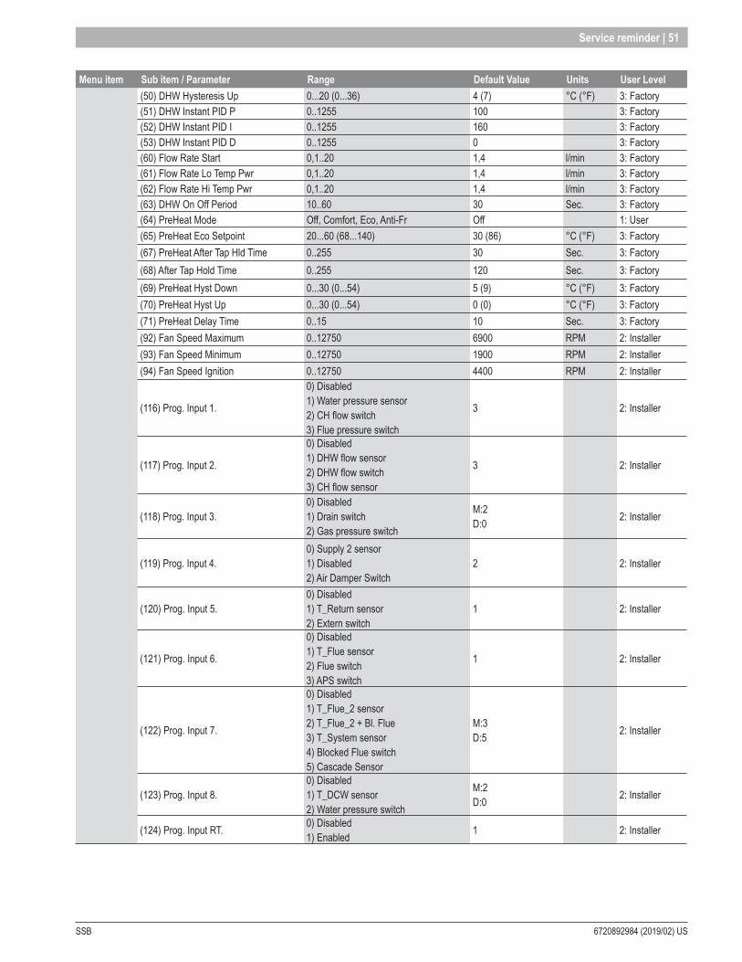
SSB 6720892984 (2019/02) US
Service reminder | 51
Menu item Sub item / Parameter Range Default Value Units User Level(50) DHW Hysteresis Up 0...20 (0...36) 4 (7) °C (°F) 3: Factory(51) DHW Instant PID P 0..1255 100 3: Factory(52) DHW Instant PID I 0..1255 160 3: Factory(53) DHW Instant PID D 0..1255 0 3: Factory(60) Flow Rate Start 0,1..20 1,4 l/min 3: Factory(61) Flow Rate Lo Temp Pwr 0,1..20 1,4 l/min 3: Factory(62) Flow Rate Hi Temp Pwr 0,1..20 1,4 l/min 3: Factory(63) DHW On Off Period 10..60 30 Sec. 3: Factory(64) PreHeat Mode Off, Comfort, Eco, Anti-Fr Off 1: User(65) PreHeat Eco Setpoint 20...60 (68...140) 30 (86) °C (°F) 3: Factory(67) PreHeat After Tap Hld Time 0..255 30 Sec. 3: Factory(68) After Tap Hold Time 0..255 120 Sec. 3: Factory(69) PreHeat Hyst Down 0...30 (0...54) 5 (9) °C (°F) 3: Factory(70) PreHeat Hyst Up 0...30 (0...54) 0 (0) °C (°F) 3: Factory(71) PreHeat Delay Time 0..15 10 Sec. 3: Factory(92) Fan Speed Maximum 0..12750 6900 RPM 2: Installer(93) Fan Speed Minimum 0..12750 1900 RPM 2: Installer(94) Fan Speed Ignition 0..12750 4400 RPM 2: Installer
(116) Prog. Input 1.
0) Disabled 1) Water pressure sensor 2) CH flow switch 3) Flue pressure switch
3 2: Installer
(117) Prog. Input 2.
0) Disabled 1) DHW flow sensor 2) DHW flow switch 3) CH flow sensor
3 2: Installer
(118) Prog. Input 3.0) Disabled 1) Drain switch 2) Gas pressure switch
M:2D:0 2: Installer
(119) Prog. Input 4.0) Supply 2 sensor 1) Disabled 2) Air Damper Switch
2 2: Installer
(120) Prog. Input 5.0) Disabled 1) T_Return sensor 2) Extern switch
1 2: Installer
(121) Prog. Input 6.
0) Disabled 1) T_Flue sensor 2) Flue switch 3) APS switch
1 2: Installer
(122) Prog. Input 7.
0) Disabled 1) T_Flue_2 sensor 2) T_Flue_2 + Bl. Flue 3) T_System sensor 4) Blocked Flue switch 5) Cascade Sensor
M:3D:5 2: Installer
(123) Prog. Input 8.0) Disabled 1) T_DCW sensor 2) Water pressure switch
M:2D:0 2: Installer
(124) Prog. Input RT. 0) Disabled 1) Enabled 1 2: Installer
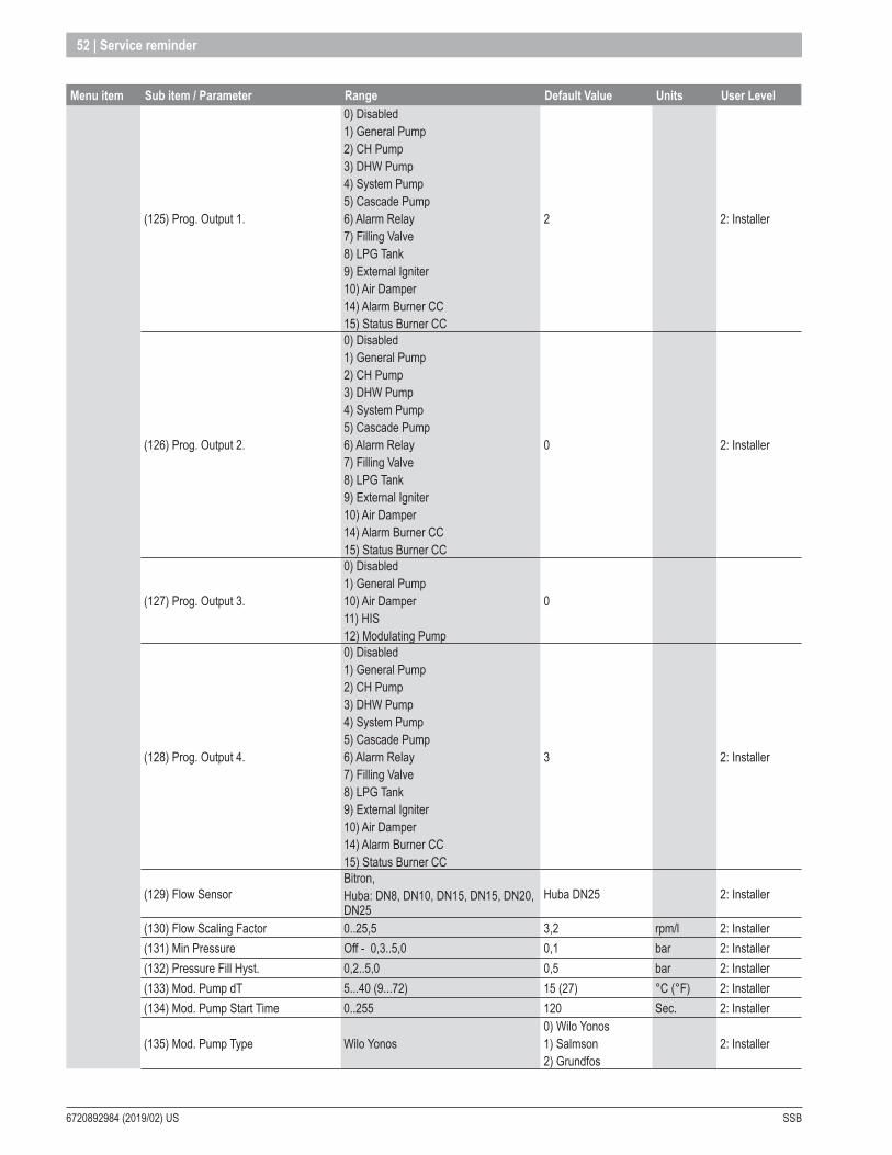
6720892984 (2019/02) US SSB
52 | Service reminder
Menu item Sub item / Parameter Range Default Value Units User Level
(125) Prog. Output 1.
0) Disabled 1) General Pump 2) CH Pump 3) DHW Pump 4) System Pump 5) Cascade Pump 6) Alarm Relay7) Filling Valve 8) LPG Tank9) External Igniter 10) Air Damper14) Alarm Burner CC15) Status Burner CC
2 2: Installer
(126) Prog. Output 2.
0) Disabled 1) General Pump 2) CH Pump 3) DHW Pump 4) System Pump 5) Cascade Pump 6) Alarm Relay7) Filling Valve 8) LPG Tank9) External Igniter 10) Air Damper14) Alarm Burner CC15) Status Burner CC
0 2: Installer
(127) Prog. Output 3.
0) Disabled 1) General Pump10) Air Damper 11) HIS12) Modulating Pump
0
(128) Prog. Output 4.
0) Disabled 1) General Pump 2) CH Pump 3) DHW Pump 4) System Pump 5) Cascade Pump 6) Alarm Relay7) Filling Valve 8) LPG Tank9) External Igniter 10) Air Damper14) Alarm Burner CC15) Status Burner CC
3 2: Installer
(129) Flow SensorBitron,Huba: DN8, DN10, DN15, DN15, DN20, DN25
Huba DN25 2: Installer
(130) Flow Scaling Factor 0..25,5 3,2 rpm/l 2: Installer(131) Min Pressure Off - 0,3..5,0 0,1 bar 2: Installer(132) Pressure Fill Hyst. 0,2..5,0 0,5 bar 2: Installer(133) Mod. Pump dT 5...40 (9...72) 15 (27) °C (°F) 2: Installer(134) Mod. Pump Start Time 0..255 120 Sec. 2: Installer
(135) Mod. Pump Type Wilo Yonos0) Wilo Yonos1) Salmson 2) Grundfos
2: Installer
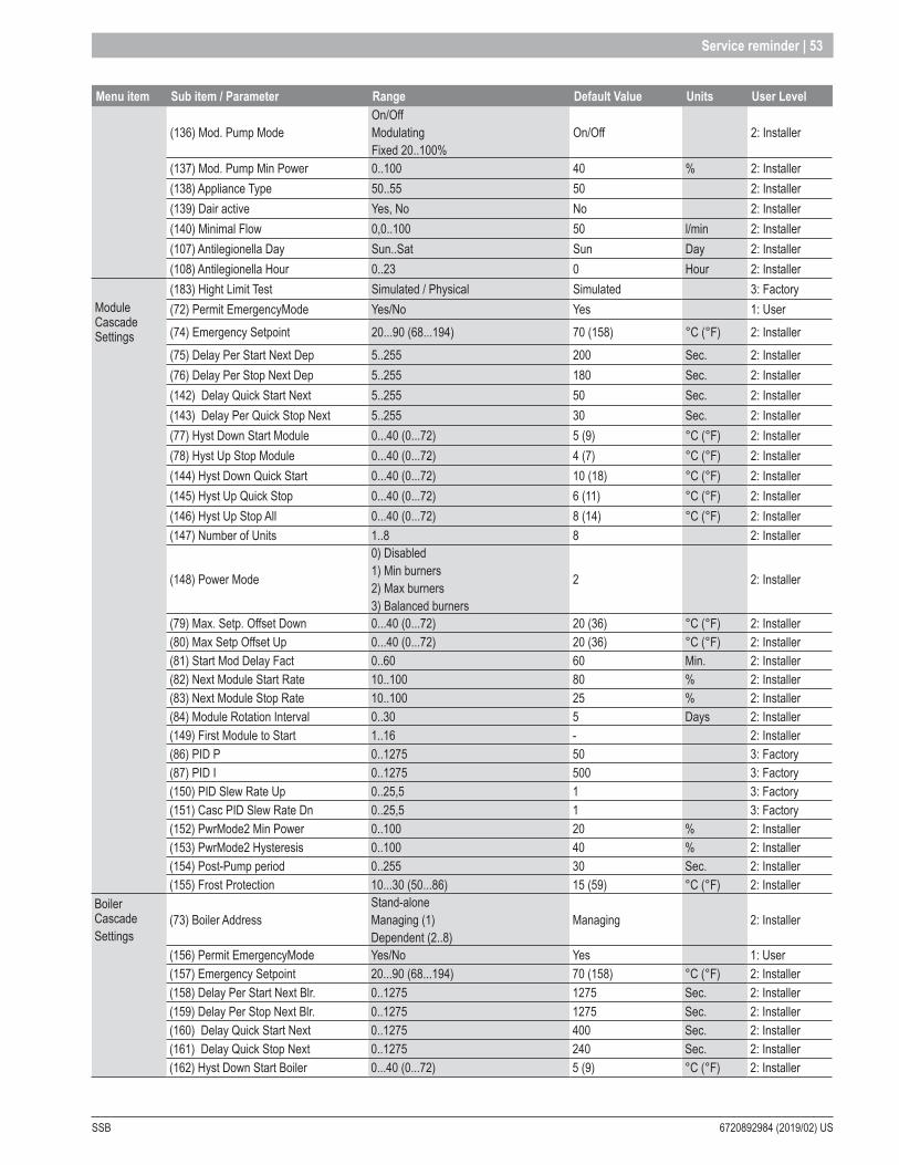
SSB 6720892984 (2019/02) US
Service reminder | 53
Menu item Sub item / Parameter Range Default Value Units User Level
(136) Mod. Pump ModeOn/OffModulatingFixed 20..100%
On/Off 2: Installer
(137) Mod. Pump Min Power 0..100 40 % 2: Installer(138) Appliance Type 50..55 50 2: Installer(139) Dair active Yes, No No 2: Installer(140) Minimal Flow 0,0..100 50 l/min 2: Installer(107) Antilegionella Day Sun..Sat Sun Day 2: Installer(108) Antilegionella Hour 0..23 0 Hour 2: Installer(183) Hight Limit Test Simulated / Physical Simulated 3: Factory
Module Cascade Settings
(72) Permit EmergencyMode Yes/No Yes 1: User (74) Emergency Setpoint 20...90 (68...194) 70 (158) °C (°F) 2: Installer(75) Delay Per Start Next Dep 5..255 200 Sec. 2: Installer(76) Delay Per Stop Next Dep 5..255 180 Sec. 2: Installer(142) Delay Quick Start Next 5..255 50 Sec. 2: Installer(143) Delay Per Quick Stop Next 5..255 30 Sec. 2: Installer(77) Hyst Down Start Module 0...40 (0...72) 5 (9) °C (°F) 2: Installer(78) Hyst Up Stop Module 0...40 (0...72) 4 (7) °C (°F) 2: Installer(144) Hyst Down Quick Start 0...40 (0...72) 10 (18) °C (°F) 2: Installer(145) Hyst Up Quick Stop 0...40 (0...72) 6 (11) °C (°F) 2: Installer(146) Hyst Up Stop All 0...40 (0...72) 8 (14) °C (°F) 2: Installer(147) Number of Units 1..8 8 2: Installer
(148) Power Mode
0) Disabled 1) Min burners2) Max burners3) Balanced burners
2 2: Installer
(79) Max. Setp. Offset Down 0...40 (0...72) 20 (36) °C (°F) 2: Installer(80) Max Setp Offset Up 0...40 (0...72) 20 (36) °C (°F) 2: Installer(81) Start Mod Delay Fact 0..60 60 Min. 2: Installer(82) Next Module Start Rate 10..100 80 % 2: Installer(83) Next Module Stop Rate 10..100 25 % 2: Installer(84) Module Rotation Interval 0..30 5 Days 2: Installer(149) First Module to Start 1..16 - 2: Installer(86) PID P 0..1275 50 3: Factory(87) PID I 0..1275 500 3: Factory(150) PID Slew Rate Up 0..25,5 1 3: Factory(151) Casc PID Slew Rate Dn 0..25,5 1 3: Factory(152) PwrMode2 Min Power 0..100 20 % 2: Installer(153) PwrMode2 Hysteresis 0..100 40 % 2: Installer(154) Post-Pump period 0..255 30 Sec. 2: Installer(155) Frost Protection 10...30 (50...86) 15 (59) °C (°F) 2: Installer
Boiler CascadeSettings
(73) Boiler AddressStand-aloneManaging (1)Dependent (2..8)
Managing 2: Installer
(156) Permit EmergencyMode Yes/No Yes 1: User(157) Emergency Setpoint 20...90 (68...194) 70 (158) °C (°F) 2: Installer(158) Delay Per Start Next Blr. 0..1275 1275 Sec. 2: Installer(159) Delay Per Stop Next Blr. 0..1275 1275 Sec. 2: Installer(160) Delay Quick Start Next 0..1275 400 Sec. 2: Installer(161) Delay Quick Stop Next 0..1275 240 Sec. 2: Installer(162) Hyst Down Start Boiler 0...40 (0...72) 5 (9) °C (°F) 2: Installer

6720892984 (2019/02) US SSB
54 | Service reminder
Menu item Sub item / Parameter Range Default Value Units User Level(163) Hyst Up Stop Boiler 0...40 (0...72) 2 (4) °C (°F) 2: Installer(164) Hyst Down Quick Start 0...40 (0...72) 10 (18) °C (°F) 2: Installer(165) Hyst Up Quick Stop 0...40 (0...72) 4 (7) °C (°F) 2: Installer(166) Hyst Up Stop All 0...60 (0...108) 8 (14) °C (°F) 2: Installer(167) Number of boilers 1..8 1 2: Installer
(168) Power Mode0) Disabled2) Max burners3) Balanced burners
2 2: Installer
(169) Max. Setp. Offset Down 0...40 (0...72) 20 (36) °C (°F) 2: Installer(170) Max Setp Offset Up 0...40 (0...72) 20 (36) °C (°F) 2: Installer(171) Start Mod Delay Fact 0..60 20 Min. 2: Installer(172) Next Boiler Start Rate 10..100 80 % 2: Installer(173) Next Boiler Stop Rate 10..100 25 % 2: Installer(174) Boiler Rotation Interval 0..30 5 Days 2: Installer(175) First Boiler to Start 1..8 - 2: Installer(176) PID P 0..1275 25 3: Factory(177) PID I 0..1275 1000 3: Factory(178) PID Slew Rate Up 0..25,5 1 3: Factory(179) PID Slew Rate Dn 0..25,5 1 3: Factory(180) PwrMode2 Min Power 0..100 20 % 2: Installer(181) PwrMode2 Hysteresis 0..100 40 % 2: Installer(182) Post-Pump period 0..255 30 Sec. 2: Installer
Appendix D - Control System Technical SpecificationsThe 900 series burner controls have the following specifications:
Power Supply 230V/120VAC (-15%, +10%) 40Hz to 70Hz
Ambient TemperatureFunctional
Storage
-15 to +70°C (5°F to +158°F) (Peak temperatures, not continuous) -25°C to +75°C (-13°F to 167°F)
Humidity 900MN: 93% RV at 25°C (77°F) Fuses Mains input 1 x 5AT, 250VFlame establishing period 2 secondsSafety time 5 secondsIgnition attempts 3
Pre purge time ≥ 2..60 seconds (not safety critical) Default: 6s
Pre ignition time 2 seconds (not safety critical)Flame failure response time < 1,0 secondFlame-detection Ionization measurement via separate ionization rod
Flame-currentMinimumStart-detectionMaximum
1.0 μA1,5 μA 14.0 μA (only max. on measurement inside control)
Protection According to EN60529 IP00; Protection against electrical shock must be guaranteed by the appliance manufacturer.
Standards Europe: CE EN298:2003
Cable length AL-BUS ²)
AGW232018 1715
A(mm2)0,25 0,50,71 1,5
Cable length (m)100 (328.1ft) 200 (656.2ft) 300 (984.3ft) 400 (1312.3ft)600 (1968.5ft)

SSB 6720892984 (2019/02) US
Service reminder | 55
Dimensions (900MN) L× W × H 212×152×47mm (8,35”×5.98”×1,85”)Weight (900MN) 530 gram
2) This consists the total length of the cable, not the length between two boilers. The length differs with the diameter of the cable.
Appendix E - NTC sensor curve selection (Rev 3 .0 .0 .0)The NTC curve of each sensor can be changed between LabVision PC software. The NTC curve can be selected from a list of pre-defined curves.
Setting NTC Curve0 NTC 10K @ 25°C B34351 NTC 10K @ 25°C B39772 NTC 10K @ 25°C B376010 NTC 10K @ 20°C B345720 NTC 12K @ 25°C B374030 NTC 12K @ 25°C B3970
(*) Duplex safety sensors cannot be adjusted freely.
Appendix F - 5 Error table (Rev . 4 .0 .905 .17114)In the next tables a description of all different errors is given.
Errors can be divided in three groups: • Non-volatile locking errors (can only be reset by the reset button).• Blocking errors (will disappear when error is gone)• Warnings (will disappear when the warning is gone, also isn’t stored in the e2prom)
When the control is in error the pump will be running. This is to prevent the freezing of the Central Heating circuit when the boiler is in error during the winter period. For some non-volatile lockouts the pump will not be running, also see the error tables in this chapter for more details.
F .1 Boiler history and time stampsBoiler History Via the Boiler History screen in the LabVision PC software the following history data is shown:• Successful ignitions• Failed Ignitions• Flame Failures• Hours in Operation• CH Burner Minutes• DHW Burner Minutes

6720892984 (2019/02) US SSB
56 | Service reminder
Error History The last 15 lockout and 15 blocking errors are stored in the boiler control. This boiler history can be shown via the Boiler History screen in LabVision or via the installer boiler status menu in one of the advanced epHS displays.
Time Stamp A time stamp will be added to an error at the moment the error occurs. The time between this error and a new error will be counted. The interval between an error and the previous error is shown as interval time in minutes, hours, days or weeks.The previous error codes are also shown in LabVision (also see the image on the following page).
Successful ignitions To prevent wear on the e2prom of the boiler control, the successful ignitions are only saved after 16 successful ignitions. When a power cycle is performed after 15 successful ignitions, these 15 ignitions are not counted.
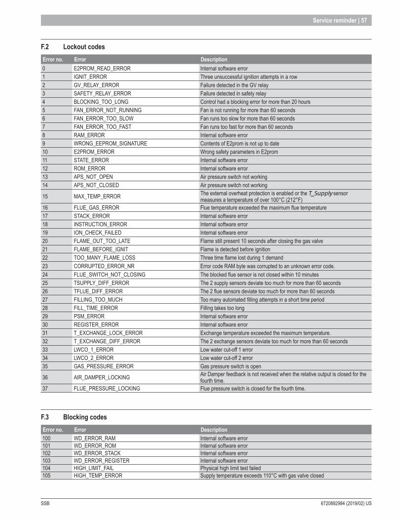
SSB 6720892984 (2019/02) US
Service reminder | 57
F .2 Lockout codesError no . Error Description0 E2PROM_READ_ERROR Internal software error1 IGNIT_ERROR Three unsuccessful ignition attempts in a row2 GV_RELAY_ERROR Failure detected in the GV relay3 SAFETY_RELAY_ERROR Failure detected in safety relay4 BLOCKING_TOO_LONG Control had a blocking error for more than 20 hours5 FAN_ERROR_NOT_RUNNING Fan is not running for more than 60 seconds6 FAN_ERROR_TOO_SLOW Fan runs too slow for more than 60 seconds7 FAN_ERROR_TOO_FAST Fan runs too fast for more than 60 seconds8 RAM_ERROR Internal software error9 WRONG_EEPROM_SIGNATURE Contents of E2prom is not up to date10 E2PROM_ERROR Wrong safety parameters in E2prom11 STATE_ERROR Internal software error12 ROM_ERROR Internal software error13 APS_NOT_OPEN Air pressure switch not working14 APS_NOT_CLOSED Air pressure switch not working
15 MAX_TEMP_ERROR The external overheat protection is enabled or the T_Supply sensor measures a temperature of over 100°C (212°F)
16 FLUE_GAS_ERROR Flue temperature exceeded the maximum flue temperature17 STACK_ERROR Internal software error18 INSTRUCTION_ERROR Internal software error19 ION_CHECK_FAILED Internal software error20 FLAME_OUT_TOO_LATE Flame still present 10 seconds after closing the gas valve21 FLAME_BEFORE_IGNIT Flame is detected before ignition22 TOO_MANY_FLAME_LOSS Three time flame lost during 1 demand23 CORRUPTED_ERROR_NR Error code RAM byte was corrupted to an unknown error code.24 FLUE_SWITCH_NOT_CLOSING The blocked flue sensor is not closed within 10 minutes25 TSUPPLY_DIFF_ERROR The 2 supply sensors deviate too much for more than 60 seconds26 TFLUE_DIFF_ERROR The 2 flue sensors deviate too much for more than 60 seconds27 FILLING_TOO_MUCH Too many automated filling attempts in a short time period28 FILL_TIME_ERROR Filling takes too long29 PSM_ERROR Internal software error30 REGISTER_ERROR Internal software error31 T_EXCHANGE_LOCK_ERROR Exchange temperature exceeded the maximum temperature.32 T_EXCHANGE_DIFF_ERROR The 2 exchange sensors deviate too much for more than 60 seconds33 LWCO_1_ERROR Low water cut-off 1 error34 LWCO_2_ERROR Low water cut-off 2 error35 GAS_PRESSURE_ERROR Gas pressure switch is open
36 AIR_DAMPER_LOCKING Air Damper feedback is not received when the relative output is closed for the fourth time.
37 FLUE_PRESSURE_LOCKING Flue pressure switch is closed for the fourth time.
F .3 Blocking codes Error no . Error Description100 WD_ERROR_RAM Internal software error101 WD_ERROR_ROM Internal software error102 WD_ERROR_STACK Internal software error103 WD_ERROR_REGISTER Internal software error104 HIGH_LIMIT_FAIL Physical high limit test failed105 HIGH_TEMP_ERROR Supply temperature exceeds 110°C with gas valve closed
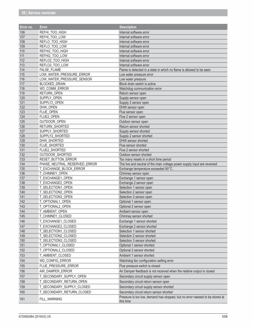
6720892984 (2019/02) US SSB
58 | Service reminder
Error no . Error Description106 REFHI_TOO_HIGH Internal software error107 REFHI_TOO_LOW Internal software error108 REFLO_TOO_HIGH Internal software error109 REFLO_TOO_LOW Internal software error110 REFHI2_TOO_HIGH Internal software error111 REFHI2_TOO_LOW Internal software error112 REFLO2_TOO_HIGH Internal software error113 REFLO2_TOO_LOW Internal software error114 FALSE_FLAME Flame is detected in a state in which no flame is allowed to be seen115 LOW_WATER_PRESSURE_ERROR Low water pressure error116 LOW_WATER_PRESSURE_SENSOR Low water pressure117 BLOCKED_DRAIN Block drain switch is active118 WD_COMM_ERROR Watchdog communication error119 RETURN_OPEN Return sensor open120 SUPPLY_OPEN Supply sensor open121 SUPPLY2_OPEN Supply 2 sensor open122 DHW_OPEN DHW sensor open123 FLUE_OPEN Flue sensor open124 FLUE2_OPEN Flue 2 sensor open125 OUTDOOR_OPEN Outdoor sensor open126 RETURN_SHORTED Return sensor shorted127 SUPPLY_SHORTED Supply sensor shorted128 SUPPLY2_SHORTED Supply 2 sensor shorted129 DHW_SHORTED DHW sensor shorted130 FLUE_SHORTED Flue sensor shorted131 FLUE2_SHORTED Flue 2 sensor shorted132 OUTDOOR_SHORTED Outdoor sensor shorted133 RESET_BUTTON_ERROR Too many resets in a short time period134 PHASE_NEUTRAL_RESERVED_ERROR The live and neutral of the main voltage power supply input are reversed135 T_EXCHANGE_BLOCK_ERROR Exchange temperature exceeded 90°C.136 T_CHIMNEY_OPEN Chimney sensor open137 T_EXCHANGE1_OPEN Exchange 1 sensor open138 T_EXCHANGE2_OPEN Exchange 2 sensor open139 T_SELECTION1_OPEN Selection 1 sensor open140 T_SELECTION2_OPEN Selection 2 sensor open141 T_SELECTION3_OPEN Selection 3 sensor open142 T_OPTIONAL1_OPEN Optional 1 sensor open143 T_OPTIONAL2_OPEN Optional 2 sensor open144 T_AMBIENT_OPEN Ambient sensor open145 T_CHIMNEY_CLOSED Chimney sensor shorted146 T_EXCHANGE1_CLOSED Exchange 1 sensor shorted147 T_EXCHANGE2_CLOSED Exchange 2 sensor shorted148 T_SELECTION1_CLOSED Selection 1 sensor shorted149 T_SELECTION2_CLOSED Selection 2 sensor shorted150 T_SELECTION3_CLOSED Selection 3 sensor shorted151 T_OPTIONAL1_CLOSED Optional 1 sensor shorted152 T_OPTIONAL2_CLOSED Optional 2 sensor shorted153 T_AMBIENT_CLOSED Ambient 1 sensor shorted154 WD_CONFIG_ERROR Watchdog fan configuration setting error155 FLUE_PRESSURE_ERROR Flue pressure switch is closed156 AIR_DAMPER_ERROR Air Damper feedback is not received when the relative output is closed157 T_SECONDARY_SUPPLY_OPEN Secondary circuit supply sensor open158 T_SECONDARY_RETURN_OPEN Secondary circuit return sensor open159 T_SECONDARY_SUPPLY_CLOSED Secondary circuit supply sensor shorted160 T_SECONDARY_RETURN_CLOSED Secondary circuit return sensor shorted
161 FILL_WARNING Pressure is too low, demand has stopped, but no error needed to be stored at this time

SSB 6720892984 (2019/02) US
Service reminder | 59
Error no . Error Description
162 FLUE_BLOCKED Flue is blocked, demand needs to be stopped with fan at ignition speed*, but no error needed to be stored at this time
163 LOWEXFLOW_PROTECTION Flow is too low, demand needs to be stopped with fan at ignition speed*, but no error needed to be stored at this time
F .4 WarningsError no . Error Description
200 CC_LOSS_COMMUNICATION Cascade System: Leading burner lost communication with one of the depending burners.
201 CC_LOSS_BOILER_COMM Cascade System: Leading boiler lost communication with one of the depending boilers.
202 OUTDOOR_WRONG Outdoor sensor is open of shorted203 T_SYSTEM_WRONG T_System sensor is open of shorted204 T_CASCADE_WRONG T_Cascade sensor is open of shorted205 MAX_HIGH_LIMIT_WARNING Too many physical high limit test attempts within 24 hours.
Appendix G - PID: Proportional-Integral-Derivative controllerFor demand handling a software PID controller is implemented.The PID controller calculates its output value as a function of the PID parameters, the setpoint and the input. The output can be used to control the fan for regulation of power, or pump for controlling the flow, depending on the application.Parameters used for the calculation are:
Input value (sensor value, such as temp.)
Setpoint
Output value PID
PARAMETERS P I D
Input value As input the parameter that needs to be controlled is given. In most cases this is a sensor temperature. This PID controller will then control this input value to the given setpoint.
Setpoint The setpoint value is the target value to which the input value is controlled to. This must be entered in the same format as the input value.
Output The output is the target power to control the input value towards the setpoint. The output value can be scaled between a minimum and maximum output so this can be used in a understandable format.
P
The P parameter of the PID-controller is used to adjust the speed of the regulation. With a larger P-factor the regulation is faster, but it is more likely to create overshoot on the regulation.
The formula is P_Power = P * Error, where the error is the difference between the setpoint and the actual temperature in 1/32 degree temperature steps. The P is a positive value when the difference (Setpoint > actual temperature) is also positive. This value is a part of the output power.
The P is a negative value when the difference is also negative (Setpoint < actual temperature). This means that this part of the output power is negative.

6720892984 (2019/02) US SSB
60 | Service reminder
I
The I parameter of the PID-controller is used to adjust the accuracy of the regulation.The I-factor keeps calculating the sum of the error between the input value and the setpoint. This keeps increasing/decreasing the output value. The I-factor is used to eliminate the error between the input value and setpoint that the P-factor cannot regulate.
The sum of the error is divided by the I-factor, which means a small I-factor means a faster response on the output. A large I-factor results in a slower response on the output.
D The D-factor is not enabled in the software.
G .1 Relay-based PID tuningRelay-based auto tuning is a simple way to tune PID controllers that avoids trial and error, and minimizes the possibility of operating the plant close to the stability limit.
As it turns out, under relay-based feedback PID tuning, most plants oscillate with a modest amplitude fortuitously at the critical frequency.
The procedure is as following:[7] In order to use relay-based tuning, this tuning mode must be enabled in the software. Set the PID- P parameter to 1, PID- I parameter to 0 and PID-
D parameter to 0 when the tuning mode is enabled.[8] Set offset parameter to the value needed to maintain at set-point for a certain load.[9] When the input is stable with amplitude d for the PID controller as shown in the figure below, also set PID- P parameter to 0. This will start the relay-
based PID tuning Oscillation.[10] Trim the offSet if necessary to get an symmetric oscillation around set-point.[11] Record the plant output amplitude a and period P.[12] The ultimate period is the observed period (P), while the ultimate gain (Ku) is inversely proportional to the observed amplitude.
Ku = ( 4 * h ) / ( π * a )
h = offSet,a = amplitude on the input.P = oscillation period.
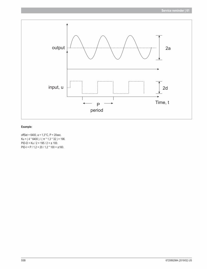
SSB 6720892984 (2019/02) US
Service reminder | 61
Pperiod
input, u
output
Time, t
2d
2a
Example:
offSet = 6400, a = 1,3°C, P = 20sec.Ku = ( 4 * 6400 ) / ( π * 1,3 * 32 ) = 196.PID-D = Ku / 2 = 195 / 2 = ± 100.PID-I = P / 1,2 = 20 / 1,2 * 100 = ±160.

6720892984 (2019/02) US SSB
62 | Service reminder
Appendix H - Cascade parameter
Specific Parameters Level(Default) Value Range°C °F °C °F
Emergency_Mode [-] 1: User Enable Enable/Disabled
Cascade_Setpoint Cascade CH Setpoint
[°C/°F] 1: User 60 140 40..93 104..200
Boiler_Address [-] 2: Installer 0 0...16 0...16Emergency_Setpoint [°C/°F] 2: Installer 70 158 20..90 68..194Delay_Period_Start_Next_DependentStart Delay Time
[sec] 2: Installer 180 0..1275
Delay_Period_Stop_Next_DependentStop Delay Time
[sec] 2: Installer 180 0..1275
Delay_Period_Start_Next_Dependent_ FasterQuick Start Interval
[sec] 2: Installer 30 0..1275
Delay_Period_Stop_Next_Dependent_ FasterQuick Stop Interval
[sec] 2: Installer 30 0..1275
Hyst_Down_Start_BurnerStart Burner Diff
[°C/°F] 2: Installer 5 9 0..20 0..36
Hyst_Up_Stop_BurnerStop Burner Diff
[°C/°F] 2: Installer 2 4 0..20 0..36
Hyst_Up_Stop_AllStop Burner Diff
[°C/°F] 2: Installer 6 11 0..30 0..54
Hyst_Down_Quick_StartStart Burner Diff in short time
[°C/°F] 2: Installer 10 18 0..20 0..36
Hyst_Up_Quick_StopStop Burner Diff in short time
[°C/°F] 2: Installer 4 7 0..20 0..36
Max_Range_Up_LimitCalculated setpoint Max offset down
[°C/°F] 2: Installer 20 36 0..20 0..36
Max_Range_Down_LimitCalculated setpoint Max offset up
[°C/°F] 2: Installer 20 36 0..20 0..36
Start_Modulation_Delay_Factor [-] 2: Installer 60 0..600 = Disabled
Next_Burner_Start_Rate [%] 2: Installer 80 10..100Next_Burner_Stop_Rate [%] 2: Installer 25 10..100
Burnerr_Rotation_Interval [days] 2: Installer 5 0..300 = Disabled
Calc_Setp_PID_P [-] 3: Factory 50 0..1275Calc_Setp_PID_I [-] 3: Factory 50 0..1275
PID_Slew_Rate_Step_UP [°C/100ms] 3: Factory 1,0 0..25,50 = Disabled
PID_Slew_Rate_Step_Down [°C/100ms] 3: Factory 1,0 0..2550 = Disabled
System_Pump_Post_Pump_Time [sec] 2: Installer 30 sec 1..90
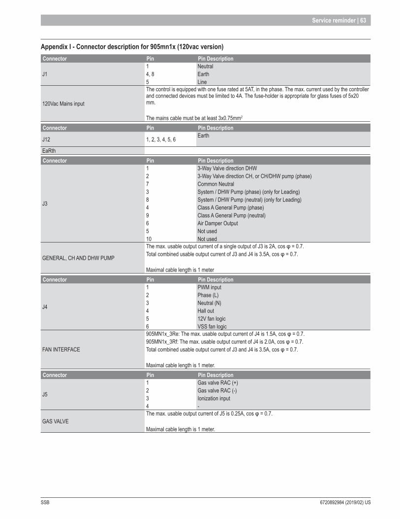
SSB 6720892984 (2019/02) US
Service reminder | 63
Appendix I - Connector description for 905mn1x (120vac version)Connector Pin Pin Description
J1 14, 8 5
NeutralEarthLine
120Vac Mains input
The control is equipped with one fuse rated at 5AT, in the phase. The max. current used by the controller and connected devices must be limited to 4A. The fuse-holder is appropriate for glass fuses of 5x20 mm.
The mains cable must be at least 3x0.75mm2
Connector Pin Pin Description
J12 1, 2, 3, 4, 5, 6 Earth
EaRth Connector Pin Pin Description
J3
12738496510
3-Way Valve direction DHW3-Way Valve direction CH, or CH/DHW pump (phase) Common Neutral System / DHW Pump (phase) (only for Leading) System / DHW Pump (neutral) (only for Leading) Class A General Pump (phase) Class A General Pump (neutral) Air Damper Output Not used Not used
GENERAL, CH AND DHW PUMP
The max. usable output current of a single output of J3 is 2A, cos φ = 0.7. Total combined usable output current of J3 and J4 is 3.5A, cos φ = 0.7.
Maximal cable length is 1 meter Connector Pin Pin Description
J4
123456
PWM input Phase (L)Neutral (N)Hall out12V fan logicVSS fan logic
FAN INTERFACE
905MN1x_3Re: The max. usable output current of J4 is 1.5A, cos φ = 0.7. 905MN1x_3Rf: The max. usable output current of J4 is 2.0A, cos φ = 0.7.Total combined usable output current of J3 and J4 is 3.5A, cos φ = 0.7.
Maximal cable length is 1 meter. Connector Pin Pin Description
J5
1234
Gas valve RAC (+) Gas valve RAC (-) Ionization input -
GAS VALVE The max. usable output current of J5 is 0.25A, cos φ = 0.7.
Maximal cable length is 1 meter.

6720892984 (2019/02) US SSB
64 | Service reminder
Connector Pin Pin Description
J6
12345678
External display (AL-BUS Data) External display (24V Power Supply) Return sensor (NTC) DHW sensor (NTC) Flue gas sensor (NTC) System sensor (NTC) Outdoor sensor (NTC) External display (AL-BUS GND)
SENSOR INPUT
NTC’s have a resistance of 10k@25°C (77°F).Temp. range NTC is -40°C to 150°C (-40°F to 300°F).
All these sensor inputs carry a voltage of 3V3 or 5V.The sensors connected to the control should be free from the appliance earth.
The maximum cable length is 1 meter. Connector Pin Pin Description
J7
12345678910
N.C.VSS for Flue/Condensate/Water pressure switch Flue Pressure switch in series with Condensate Pressure Input Water Pressure Switch (NC) (only for Leading) General pump PWM control signal Heat Exchanger Flow Sensor +5V Heat Exchanger Flow Sensor VSSHeat Exchanger Flow Sensor Pulse Gas Pressure Switch (only for Leading) VSS for General pump PWM control and Gas pressure switch
GENERAL PUMP OUTPUT Maximal cable length is 1 meter. Connector Pin Pin DescriptionJ8 1 - 2 AL-BUS connector
AL-BUS CONNECTOR Connector to connect other communication devices onto the AL-BUS communication bus or PC communication.
AL-BUS POWER SWITCH
The power ON this AL-BUS can be activated with S1 (the switch on the side): Set to “OFF” position for a controller in a burner cascade or stand-alone appliance.Set to “ON” position only on the controller of the first burner in the managing boiler of a boiler cascade (see architecture diagram for system overview).
Connector Pin Pin Description
J9
1234
0-10V InputOpen Thermostat interface or Room Thermostat ON/OFF VSS VSS
Connector Pin Pin Description
J11
1234
Low Water Cut Off 1 (only for Leading) VSS Low Water Cut Off 2 (only for Leading) VSS
Connector Pin Pin Description
J12
123456
Safety Limit (ECO) Supply Sensor (NTC) Air Damper Feedback (only for Leading)24V VSSVSS
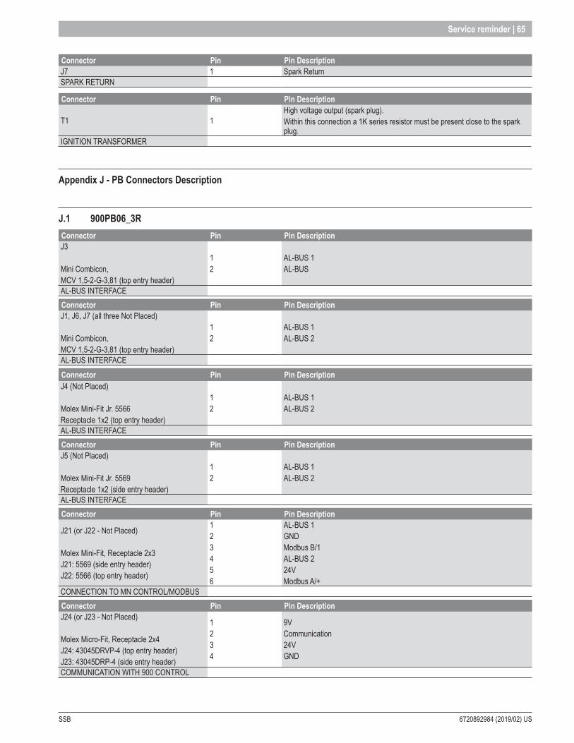
SSB 6720892984 (2019/02) US
Service reminder | 65
Connector Pin Pin DescriptionJ7 1 Spark ReturnSPARK RETURN
Connector Pin Pin Description
T1 1High voltage output (spark plug).Within this connection a 1K series resistor must be present close to the spark plug.
IGNITION TRANSFORMER
Appendix J - PB Connectors Description
J .1 900PB06_3RConnector Pin Pin DescriptionJ3
Mini Combicon, MCV 1,5-2-G-3,81 (top entry header)
12
AL-BUS 1 AL-BUS
AL-BUS INTERFACE Connector Pin Pin DescriptionJ1, J6, J7 (all three Not Placed)
Mini Combicon, MCV 1,5-2-G-3,81 (top entry header)
12
AL-BUS 1AL-BUS 2
AL-BUS INTERFACE Connector Pin Pin DescriptionJ4 (Not Placed)
Molex Mini-Fit Jr. 5566Receptacle 1x2 (top entry header)
12
AL-BUS 1AL-BUS 2
AL-BUS INTERFACE Connector Pin Pin DescriptionJ5 (Not Placed)
Molex Mini-Fit Jr. 5569 Receptacle 1x2 (side entry header)
12
AL-BUS 1AL-BUS 2
AL-BUS INTERFACE Connector Pin Pin Description
J21 (or J22 - Not Placed)
Molex Mini-Fit, Receptacle 2x3 J21: 5569 (side entry header) J22: 5566 (top entry header)
123456
AL-BUS 1 GND Modbus B/1 AL-BUS 2 24V Modbus A/+
CONNECTION TO MN CONTROL/MODBUSConnector Pin Pin DescriptionJ24 (or J23 - Not Placed)
Molex Micro-Fit, Receptacle 2x4 J24: 43045DRVP-4 (top entry header) J23: 43045DRP-4 (side entry header)
1234
9V Communication 24V GND
COMMUNICATION WITH 900 CONTROL

6720892984 (2019/02) US SSB
66 | Service reminder
J .2 905PB05_3R Display
J .2 .1 ConnectorsThe following connectors are present on the 905PB_3R Display:
J7
J18/J27FRONT BACK
J25
J2/J26
Connector Mini Combicon Connector Modular jackJ1 MCV 1,5-2-G-3,81 (top entry) J25 6P/6C
J18/J27 J2/J26
are 2-pin and 5-pin connectors that can be used for programming
J .2 .2 Connection diagram
905P
B0X_
3R
J7-02J7-01AL-BUS
RS485 / Mod BUS
AL-BUS
J25-2J25-1
J25-3
J25-5J25-4
J25-6
BGND
AL_COMMA
VSS+24V
905PB05_3RConnector FunctionJ7 PC interfaceJ25 Connection to MN control/Modbus
J .2 .3 J25 Connector (on 905PB05_3R)
J25 Wire Colors:J25-1: GreyJ25-2: BlackJ25-3: GreenJ25-4: YellowJ25-5: RedJ25-6: Blue
1: GND/VSS2: ModBus_B (= Data -)3: ModBus_A (= Data +)3: AL_Comm5: VSS6: +24V
To 905MN1 2 3 4 5 6

SSB 6720892984 (2019/02) US
Service reminder | 67
Appendix K - Modbus
K .1 Modbus ConfigurationThe table below summarizes the Modbus configuration details.
Protocol Modbus RTU.
Default dependent address Configurable with 900PB or LabVision. Default: 1
Supported Modbus commandsRead Holding registers (03)Write single holding register (06)Write multiple holding registers (10)
Baud rate 9600 bps.Data Length 8Parity None
Stop Bits 1/2, Configurable with 900PB or LabVision. Default: 2 stop bits
Physical layer RS485 (two wire + optional GND)
K .2 Holding registersDepending on the type of Modbus software used, the holding register addressing range starts either at 0x0000 or at 0x0001.If your Modbus software starts addressing from 0x0000 you can use the holding register addresses shown in the table above.If your Modbus software addressing range starts at 0x0001 then add 1 to the holding register addresses listed in the table above. This is also applicable for the various test tools available for Modbus.
Holding registers that support writing can only be written to when writing is enabled.Writing can be enabled by setting the ‘Write enable’ bit in the ‘Control register’ (Also see chapter “K.4 Control register” and “K.4.1 Write Enable”).
K .3 Overview
K .3 .1 General Modbus Control/Status registers (95 - 99)Depending on the type of Modbus software used, the holding register addressing range starts either at 0x0000 or at 0x0001.
Holding register
AccessDescription Automatic
Conversion RangeR W
General Modbus Control/Status registers95 005F X Group number 850 / 90097 0061 X Modbus Device type / table 20 = 900PB
98 0062 X X Unit selection (see paragraph “K.5 Unit selection” pag. 71 for more details)
Bit0: °C / °F Bit1: bar / psi
99 0063 X X Control register (see paragraph “K.4 Control register” pag. 71 for more details)
Bit0: Write Enable.Bit14: Controller reset.
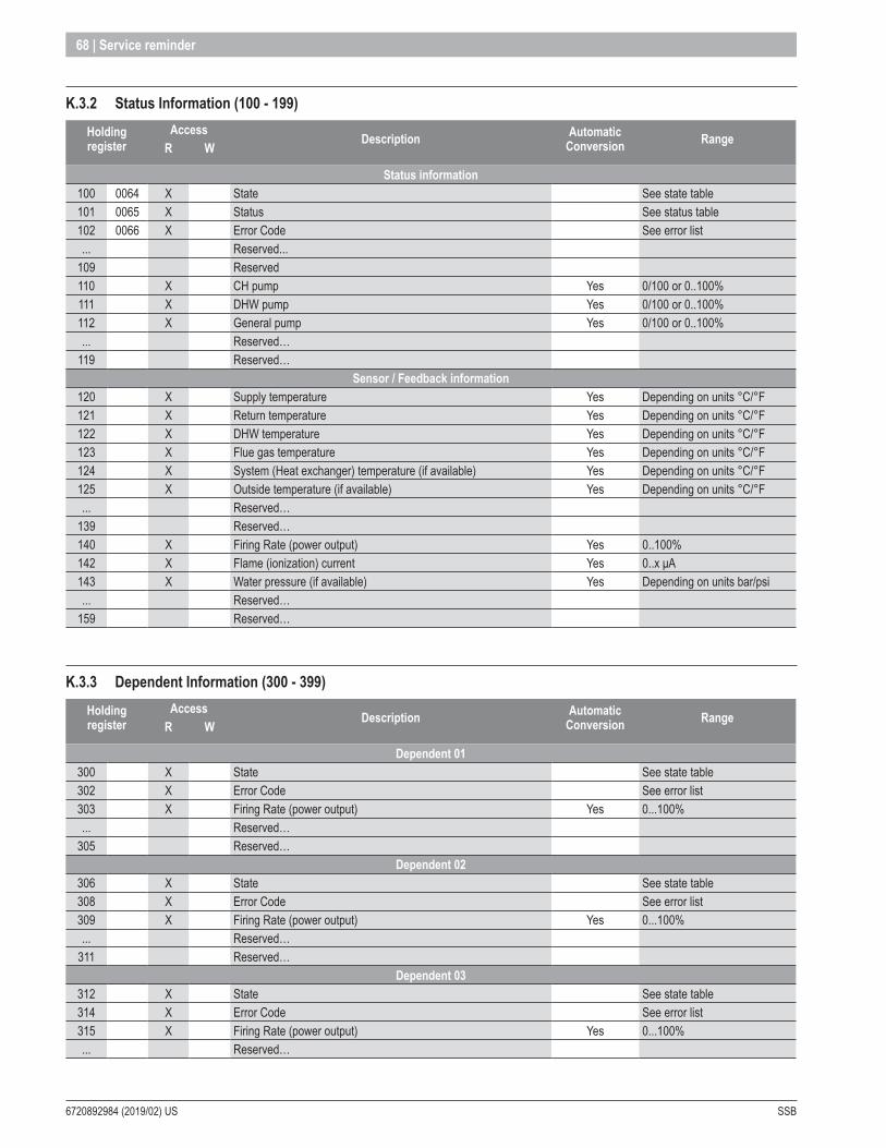
6720892984 (2019/02) US SSB
68 | Service reminder
K .3 .2 Status Information (100 - 199)Holding register
AccessDescription Automatic
Conversion RangeR W
Status information100 0064 X State See state table101 0065 X Status See status table102 0066 X Error Code See error list... Reserved...
109 Reserved110 X CH pump Yes 0/100 or 0..100%111 X DHW pump Yes 0/100 or 0..100%112 X General pump Yes 0/100 or 0..100%... Reserved…
119 Reserved…Sensor / Feedback information
120 X Supply temperature Yes Depending on units °C/°F121 X Return temperature Yes Depending on units °C/°F122 X DHW temperature Yes Depending on units °C/°F123 X Flue gas temperature Yes Depending on units °C/°F124 X System (Heat exchanger) temperature (if available) Yes Depending on units °C/°F125 X Outside temperature (if available) Yes Depending on units °C/°F... Reserved…
139 Reserved…140 X Firing Rate (power output) Yes 0..100%142 X Flame (ionization) current Yes 0..x μA143 X Water pressure (if available) Yes Depending on units bar/psi... Reserved…
159 Reserved…
K .3 .3 Dependent Information (300 - 399)Holding register
AccessDescription Automatic
Conversion RangeR W
Dependent 01300 X State See state table302 X Error Code See error list303 X Firing Rate (power output) Yes 0...100%... Reserved…
305 Reserved…Dependent 02
306 X State See state table308 X Error Code See error list309 X Firing Rate (power output) Yes 0...100%... Reserved…
311 Reserved…Dependent 03
312 X State See state table314 X Error Code See error list315 X Firing Rate (power output) Yes 0...100%... Reserved…
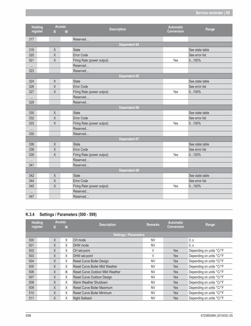
SSB 6720892984 (2019/02) US
Service reminder | 69
Holding register
AccessDescription Automatic
Conversion RangeR W
317 Reserved…Dependent 04
318 X State See state table320 X Error Code See error list321 X Firing Rate (power output) Yes 0...100%... Reserved…
323 Reserved…Dependent 05
324 X State See state table326 X Error Code See error list327 X Firing Rate (power output) Yes 0...100%... Reserved…
329 Reserved…Dependent 06
330 X State See state table332 X Error Code See error list333 X Firing Rate (power output) Yes 0...100%... Reserved…
335 Reserved…Dependent 07
336 X State See state table338 X Error Code See error list339 X Firing Rate (power output) Yes 0...100%... Reserved…
341 Reserved…Dependent 08
342 X State See state table344 X Error Code See error list345 X Firing Rate (power output) Yes 0...100%... Reserved…
347 Reserved…
K .3 .4 Settings / Parameters (500 - 599)Holding register
AccessDescription Remarks Automatic
Conversion RangeR W
Settings / Parameters500 X X CH mode NV 0..x501 X X DHW mode NV 0..x502 X X CH set-point V Yes Depending on units °C/°F503 X X DHW set-point V Yes Depending on units °C/°F504 X X Reset Curve Boiler Design NV Yes Depending on units °C/°F505 X X Reset Curve Boiler Mild Weather NV Yes Depending on units °C/°F506 X X Reset Curve Outdoor Mild Weather NV Yes Depending on units °C/°F507 X X Reset Curve Outdoor Design NV Yes Depending on units °C/°F508 X X Warm Weather Shutdown NV Yes Depending on units °C/°F509 X X Reset Curve Boiler Maximum NV Yes Depending on units °C/°F510 X X Reset Curve Boiler Minimum NV Yes Depending on units °C/°F511 X X Night Setback NV Yes Depending on units °C/°F

6720892984 (2019/02) US SSB
70 | Service reminder
Holding register
AccessDescription Remarks Automatic
Conversion RangeR W
... Reserved…599 Reserved…
aaREMARKSNV Non-Volatile means that the parameter is stored in the non-volatile memory (eeprom, flash, etc). These parameters will retain their value after a reset/power cycle. However the parameters have a limited amount of allowed write cycles (10.000 times, average of 2 times per day), which means these parameters cannot be used for dynamic control!
V Volatile, means that the parameter is stored in the volatile memory (RAM). These parameters will lose their value after a reset/power cycle (value will be reset to the last know setting from non-volatile memory). These parameters can be written unlimited and can be used for dynamic control. The Error Log items can be read in blocks of 8 holding registers from error log index 0 to 47 (total 48 error log items).
K .3 .5 Service Reminder (1500 – 1550)The Service Reminder status and settings can be read/written using the following holding registers.To check if the Service Reminder is active, the Hours_Till_Service (1501) holding register should be read.When the Hours_Till_Service value is 0 the service reminder is active.
Holding registerAcces
Description Automatic Conversion Range
R W
Service Reminder Counters
1500 X Hours since last service (Burn hours or operation hours, depends on the Service_Hour_Counter setting). 0…65534 hours.
1501 XHours till service is required (Burn hours or operation hours, depends on the Service_Hour_Counter setting).
0…Service_Interval
... Reserved…Service Settings
1530 X X Reset Service Reminder. 0…1 (1=Reset).
1531 X X Service Hour Counter setting. The counted hours (1500 + 1501) are burn / operation hours.
0=Burn hours, 1=Operation hours.
1532 X X Service Interval. 0…25500 hours (Steps of 100 hours).
1533 X X Service Shutdown Period (after service reminder is active). 0…25500 hours (Steps of 100 hours).
NOTE: A Overdue counter value of 0xFFFF means that the counter is not available/empty.
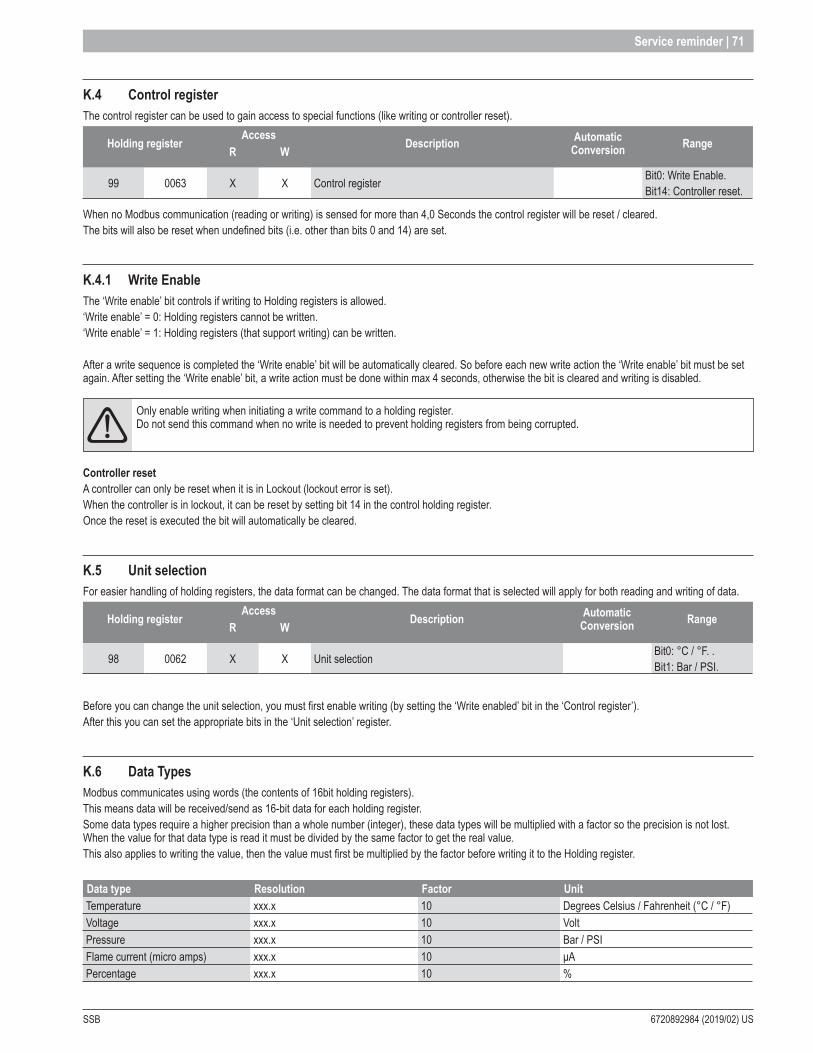
SSB 6720892984 (2019/02) US
Service reminder | 71
K .4 Control registerThe control register can be used to gain access to special functions (like writing or controller reset).
Holding registerAccess
Description Automatic Conversion Range
R W
99 0063 X X Control register Bit0: Write Enable.Bit14: Controller reset.
When no Modbus communication (reading or writing) is sensed for more than 4,0 Seconds the control register will be reset / cleared. The bits will also be reset when undefined bits (i.e. other than bits 0 and 14) are set.
K .4 .1 Write EnableThe ‘Write enable’ bit controls if writing to Holding registers is allowed.‘Write enable’ = 0: Holding registers cannot be written.‘Write enable’ = 1: Holding registers (that support writing) can be written.
After a write sequence is completed the ‘Write enable’ bit will be automatically cleared. So before each new write action the ‘Write enable’ bit must be set again. After setting the ‘Write enable’ bit, a write action must be done within max 4 seconds, otherwise the bit is cleared and writing is disabled.
aaOnly enable writing when initiating a write command to a holding register. Do not send this command when no write is needed to prevent holding registers from being corrupted.
Controller resetA controller can only be reset when it is in Lockout (lockout error is set).When the controller is in lockout, it can be reset by setting bit 14 in the control holding register.Once the reset is executed the bit will automatically be cleared.
K .5 Unit selectionFor easier handling of holding registers, the data format can be changed. The data format that is selected will apply for both reading and writing of data.
Holding registerAccess
Description Automatic Conversion Range
R W
98 0062 X X Unit selection Bit0: °C / °F. .Bit1: Bar / PSI.
Before you can change the unit selection, you must first enable writing (by setting the ‘Write enabled’ bit in the ‘Control register’).After this you can set the appropriate bits in the ‘Unit selection’ register.
K .6 Data TypesModbus communicates using words (the contents of 16bit holding registers).This means data will be received/send as 16-bit data for each holding register.Some data types require a higher precision than a whole number (integer), these data types will be multiplied with a factor so the precision is not lost. When the value for that data type is read it must be divided by the same factor to get the real value.This also applies to writing the value, then the value must first be multiplied by the factor before writing it to the Holding register.
Data type Resolution Factor UnitTemperature xxx.x 10 Degrees Celsius / Fahrenheit (°C / °F)Voltage xxx.x 10 VoltPressure xxx.x 10 Bar / PSIFlame current (micro amps) xxx.x 10 μAPercentage xxx.x 10 %

6720892984 (2019/02) US SSB
72 | Service reminder
K .7 Examples: How to update a register with a Write request via Modbus
K .7 .1 Example of a simple Write commandThe following example explains how to update a register with a (simple) write request via Modbus:Address 900PB Command simple write Register to update New value Checksum01h 06h 01F6h 0262h E8D8h
K .7 .2 Example of Command-Sequences for updating the CH setpoint via ModbusThis example explains how to update the CH setpoint from value 60°C to value 61°C in the 900PB Display (Modbus address 01h) and shows the sequence of Modbus commands that have to be written:
Enable write action Command on modbus Write from … to… *Enable the control Register (99) by writing value 1 in the register 99. The register 99 will be cleared after 3 sec. from 900PB, therefore the next write command has to be send within 3 sec.
01h 06h 00h 63h 00h 01h B8h 14h Modbus-device ¨ 900PB
Ack write enabled Command on modbus Write from … to… *The ack for the simple write request is the repetition of the previous request command. 01h 06h 00h 63h 00h 01h B8h 14h 900PB ¨ Modbus Device
Write ch-setpoint value Command on modbus Write from … to… *Simple Write in register 502 (CH-Setpoint) the value 610. Send a request for update the CH- Setpoint at a value of 61°C 01h 06h 01h F6h 02h 62h E8h 8Dh Modbus Device ¨ 900PB
Ack new ch-setpoint value Command on modbus Write from … to… *The ack for the simple write request is the repetition of the previous request command 01h 06h 01h F6h 02h 62h E8h 8Dh 900PB ¨ Modbus Device
* Also see the scheme on the following page that shows the different writing actions between the Modbus Device and the 900PB .
The following scheme illustrates the examples from the previous paragraph and shows from which device to (another device) the Writing actions take place:
Enable write action Ack write enabled
Write Setpoint value
Ack new setpoint value
900PB(01h)
ModbusDevice
NOTE: Modbus Interface and Diagnostics software is available via ebm-papst Heating Systems B.V.
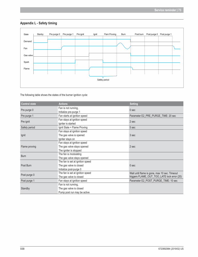
SSB 6720892984 (2019/02) US
Service reminder | 73
Appendix L - Safety timing
Stanby Pre purge 0 Pre purge 1 Pre ignit Ignit Flam Proving
Safety period
State
Demand
Fan
Gas valve
Spark
Flame
Burn Post burn Post purge 0 Post purge 1
The following table shows the states of the burner ignition cycle:
Control state Actions Setting
Pre purge 0 Fan is not running,Initialize pre-purge 1 0 sec
Pre purge 1 Fan starts at ignition speed Parameter E2_PRE_PURGE_TIME: 20 sec
Pre ignit Fan stays at ignition speed Igniter is started 2 sec
Safety period Ignit State + Flame Proving 5 sec
Ignit Fan stays at ignition speed The gas valve is opened Igniter stays on
3 sec
Flame proving Fan stays at ignition speed The gas valve stays opened The igniter is stopped
2 sec
Burn The fan is modulating The gas valve stays opened
Post Burn The fan is set at ignition speed The gas valve is closed Initialize post-purge 0
0 sec
Post purge 0 The fan is set at ignition speed The gas valve is closed
Wait until flame is gone, max 10 sec. Timeout triggers FLAME_OUT_TOO_LATE lock error (20)
Post purge 1 Fan stays at ignition speed Parameter E2_POST_PURGE_TIME: 10 sec
StandbyFan is not running,The gas valve is closed Pump post run may be active
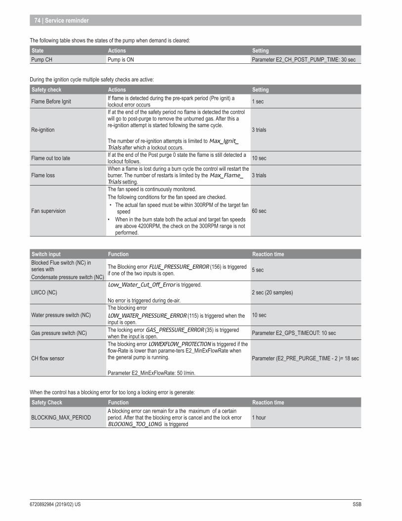
6720892984 (2019/02) US SSB
74 | Service reminder
The following table shows the states of the pump when demand is cleared:State Actions SettingPump CH Pump is ON Parameter E2_CH_POST_PUMP_TIME: 30 sec
During the ignition cycle multiple safety checks are active:Safety check Actions Setting
Flame Before Ignit If flame is detected during the pre-spark period (Pre ignit) a lockout error occurs 1 sec
Re-ignition
If at the end of the safety period no flame is detected the control will go to post-purge to remove the unburned gas. After this a re-ignition attempt is started following the same cycle.
The number of re-ignition attempts is limited to Max_Ignit_Trials after which a lockout occurs.
3 trials
Flame out too late If at the end of the Post purge 0 state the flame is still detected a lockout follows. 10 sec
Flame lossWhen a flame is lost during a burn cycle the control will restart the burner. The number of restarts is limited by the Max_Flame_Trials setting.
3 trials
Fan supervision
The fan speed is continuously monitored. The following conditions for the fan speed are checked.• The actual fan speed must be within 300RPM of the target fan
speed • When in the burn state both the actual and target fan speeds
are above 4200RPM, the check on the 300RPM range is not performed.
60 sec
Switch input Function Reaction time Blocked Flue switch (NC) in series with Condensate pressure switch (NC)
The Blocking error FLUE_PRESSURE_ERROR (156) is triggered if one of the two inputs is open. 5 sec
LWCO (NC)Low_Water_Cut_Off_Error is triggered.
No error is triggered during de-air.2 sec (20 samples)
Water pressure switch (NC)The blocking error LOW_WATER_PRESSURE_ERROR (115) is triggered when the input is open.
10 sec
Gas pressure switch (NC) The locking error GAS_PRESSURE_ERROR (35) is triggered when the input is open. Parameter E2_GPS_TIMEOUT: 10 sec
CH flow sensor
The blocking error LOWEXFLOW_PROTECTION is triggered if the flow-Rate is lower than parame-ters E2_MinExFlowRate when the general pump is running.
Parameter E2_MinExFlowRate: 50 l/min.
Parameter (E2_PRE_PURGE_TIME - 2 )= 18 sec
When the control has a blocking error for too long a locking error is generate:Safety Check Function Reaction time
BLOCKING_MAX_PERIOD A blocking error can remain for a the maximum of a certain period. After that the blocking error is cancel and the lock error BLOCKING_TOO_LONG is triggered
1 hour
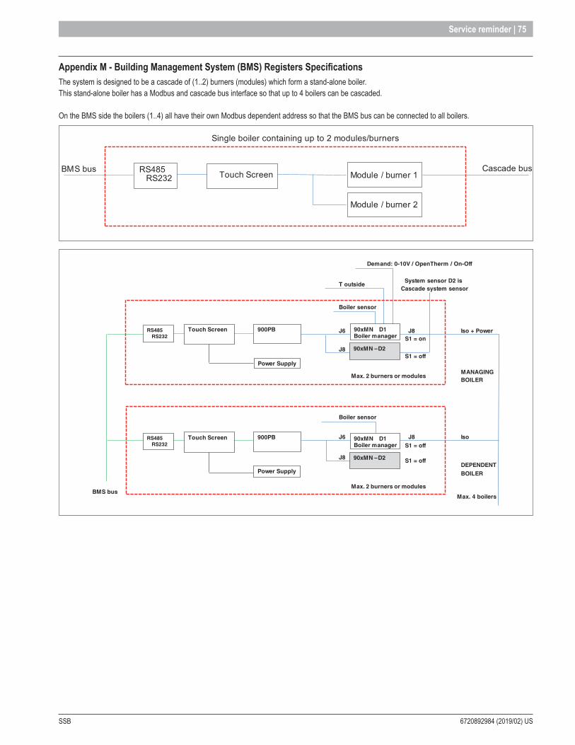
SSB 6720892984 (2019/02) US
Service reminder | 75
Appendix M - Building Management System (BMS) Registers SpecificationsThe system is designed to be a cascade of (1..2) burners (modules) which form a stand-alone boiler.This stand-alone boiler has a Modbus and cascade bus interface so that up to 4 boilers can be cascaded.
On the BMS side the boilers (1..4) all have their own Modbus dependent address so that the BMS bus can be connected to all boilers.
Single boiler containing up to 2 modules/burners
BMS bus Cascade busModule / burner 1Touch ScreenRS485
RS232
Module / burner 2
Demand: 0-10V / OpenTherm / On-Off
T outsideSystem sensor D2 is
Cascade system sensor
Boiler sensor
J6 J8 Iso + Power S1 = on
J8 S1 = off
MANAGINGBOILER
Boiler sensor
J6 J8 Iso S1 = off
J8DEPENDENT
BMS bus
S1 = off
BOILER
Max. 4 boilers
90xMN -900PBTouch Screen
Power Supply
Max. 2 burners or modules
90xMN –
––
D2
900PB
Max. 2 burners or modules
RS485RS232
Power Supply
Touch ScreenRS485RS232
90xMN D1Boiler manager
90xMN –
––
D2
90xMN D1Boiler manager

6720892984 (2019/02) US SSB
76 | Service reminder
M .1 Modbus
M .1 .1 ConfigurationThe table below summarizes the Slave Modbus configuration details for 900TS.
Protocol Modbus RTU.
Default dependent address
Boiler 1 Default: 1Boiler 2 Default: 2Boiler 3 Default: 3Boiler 4 Default: 4
Supported Modbus commandsRead Holding registers (03)Write single holding register (06)Write multiple holding registers (10)
Baud rate 9600 bps.Data Length 8Parity NoneStop Bits Default: 2 stop bitsPhysical layer RS485 (two wire + optional GND)
M .2 RegistersThe Cascade Manager controls the cascade of multiple boilers. Each boiler can have up to 8 units/burners available.
M .2 .1 Touch screenTouch screen information and settings.
CLIMATIC CURVE
HR # Access Description RangeR WClimatic curve status info
20021 X Outdoor sensor temperature -50...150°C (-58...302°F)Climatic curve settings
21000 X X Reset Curve Boiler Design 0-100°C (32-212°F)21001 X X Reset Curve Boiler Mild Weather 0-100°C (32-212°F)21002 X X Reset Curve Outdoor Mild Weather 0-100°C (32-212°F)21003 X X Reset Curve Outdoor Design 0-100°C (32-212°F)21004 X X Warm Weather Shutdown 0-100°C (32-212°F)21005 X X Reset Curve Boiler Maximum 0-100°C (32-212°F)21006 X X Reset Curve Boiler Minimum 0-100°C (32-212°F)21007 X X Night Setback 0-100°C (32-212°F)

SSB 6720892984 (2019/02) US
Service reminder | 77
M .2 .2 Boiler Cascade ManagerBoiler cascade information and settings.
BOILER CASCADE STATUS (ONLY AVAILABLE ON THE CASCADE MANAGER)
HR # Access Description RangeR WSystem status info
20000 X Power level for entire (boiler) cascade system 0-100%502 X X Cascade Ch Mode X setpoint 0-100%20001 X System supply setpoint 0-100%20020 X System supply sensor temperature -50...150°C (-58...302°F)20021 X Outdoor sensor temperature -50...150°C (-58...302°F)20060 X Cascade Pump Status 0=Off, 1=On
Boilers available20100 X Boiler 1 available / present 0=No, 1=Yes20101 X Boiler 2 available / present 0=No, 1=Yes20102 X Boiler 3 available / present 0=No, 1=Yes20103 X Boiler 4 available / present 0=No, 1=Yes
Boilers active (heating)20132 X Boiler 1 is active / heating 0=No, 1=Yes20133 X Boiler 2 is active / heating 0=No, 1=Yes20134 X Boiler 3 is active / heating 0=No, 1=Yes20135 X Boiler 4 is active / heating 0=No, 1=Yes
Boiler errors20164 X Boiler 1 has error (one or more modules / burners have an error) 0=No, 1=Yes20165 X Boiler 2 has error (one or more modules / burners have an error) 0=No, 1=Yes20166 X Boiler 3 has error (one or more modules / burners have an error) 0=No, 1=Yes20167 X Boiler 4 has error (one or more modules / burners have an error) 0=No, 1=Yes
Boiler service20196 X Boiler 1 requires service 0=No, 1=Yes20197 X Boiler 2 requires service 0=No, 1=Yes20198 X Boiler 3 requires service 0=No, 1=Yes20199 X Boiler 4 requires service 0=No, 1=Yes

6720892984 (2019/02) US SSB
78 | Service reminder
M .3 Module/Burner Cascade ManagerModule/Burner cascade information and settings.
M .3 .1 Boiler address
HR # Access Control Settings RangeR WClimatic curve status info
31000 X X Boiler address (1=Cascade / Boiler manager, 2-4=Dependent) 1 - 4
M .3 .2 Module/Burner Cascade Status
HR # Access Description RangeR WSystem status info
30000 X Power level for the boiler 0-100%30001 X Boiler supply setpoint (calculated) 0-100%30002 X Heat demand type None,CH,DHW30020 X Boiler Supply temperature 0-100%30021 X DHW temperature 0-100%30060 X CH pump running 0=Off, 1=On30061 X DHW pump status 0=Off, 1=On30080 X Burn hours (total of all unit/burner burn hours) 0-65536hr
Module/Burner available 30100 X Module/Burner 1 available / present 0=No, 1=Yes30101 X Module/Burner 2 available / present 0=No, 1=Yes
Module/Burner active (heating) (see also holding register contents “M .4 .1 Burner/Module 1 Status and Control Registers” pag . 80)40000 X Module/Burner 1 is active / heating State(*)40100 X Module/Burner 2 is active / heating State(*)
Module/Burner errors (see also holding register contents “M .4 .1 Burner/Module 1 Status and Control Registers” pag . 80)40001 X Module/Burner 1 has error 255=No error, x=Error40101 X Module/Burner 2 has error 255=No error, x=Error
The State(*) can be divided in the following steps:Standby: 0 : Initialization 1 : Reset 2 : StandbyActive: 3/4 : Pre Purge 5/6 : (Pre) Ignition 7 : Flame Proving 8/9 : Burn 10/11 : Post PurgeError: 12 : Error 13 : Alarm 14 : Warning 15 : Burner Boot

SSB 6720892984 (2019/02) US
Service reminder | 79
M .3 .3 Boiler Error LogThe Error Log items can be read in blocks of 8 holding registers from error log index 0 to 47 (total 48 error log items).
NOTE: The error log items are not ordered based on the last occurrence when more than 47 errors are stored!
HR # Access Description RangeR WLast Error Index
34000-34007
Reserved…
Error Log Index 034008 X Error Number See error list.34009 X Boiler ID: 0=Stand-Alone, 1=Managing, 2-4=Dependent. 0…434010 X Timestamp: Day Of Week 0…6 = Sunday…Saturday34011 X Timestamp: Day Of Month 1…31d34012 X Timestamp: Month 1…12m34013 X Timestamp: Year 2000…2255y34014 X Timestamp: Hour 0...23 (24h notation)34015 X Timestamp: Minute 0...59min
Error Log Index 1-4634016-34383
X Error Number 2-46
Error Log Index 4734384 X Error Number See error list.34385 X Boiler ID: 0=Stand-Alone, 1=Managing, 2-4=Dependent. 0…434386 X Timestamp: Day Of Week 0…6 = Sunday…Saturday34387 X Timestamp: Day Of Month 1…31d34388 X Timestamp: Month 1…12m34389 X Timestamp: Year 2000…2255y34390 X Timestamp: Hour 0...23 (24h notation)34391 X Timestamp: Minute 0...59min
M .3 .4 Boiler Service ReminderThe Service Reminder status and settings can be read/written using the following holding registers.To check if the Service Reminder is active, the Hours_Till_Service holding register should be read.When the Hours_Till_Service value is 0 the service reminder is active.
HR # Access Description RangeR WService Reminder Counters
33000 X Burn Hours since last service 0…65534 hours.33001 X Burn Hours till service is required 0…Service_Interval
Service Overdue Counters (history)33005 X Overdue counter 0 0…65534 hours.33006 X Overdue counter 1 0…65534 hours.33007 X Overdue counter 2 0…65534 hours.33008-33018
X Overdue counter 3-13 0…65534 hours.

6720892984 (2019/02) US SSB
80 | Service reminder
HR # Access Description RangeR W33019 X Overdue counter 14 0…65534 hours.
Service Settings33042 X Service Interval. 0…255 x 100 hours
NOTE: A Overdue counter value of 0xFFFF means that the counter is not available/empty.
M .4 Burner/Module infoEach module/burner present in the boiler has its own set of status information holding registers. Each set has the holding register offset of ((‘Unit/burner Number’ - 1) x 100) + 40000. So Burner 1 starts at holding register 40000, Burner 2 starts at 40100, etc.
M .4 .1 Burner/Module 1 Status and Control Registers
HR # Access Description RangeR WModule/Burner 1 status info
40000 X Current state of the unit/burner. State(*)40001 X Error of the unit/burner. See manual40002 X Module supply setpoint (calculated) 0-100°C (32-212°F)40003 X Power level. 0.0 - 100.0%40006 X General pump status. 0=Off, 1=On40009 X CH Flow rate. 0-255 l/min40011 X Actual fan speed. RPM
40030 X Supply sensor temperature. -50...150°C (-58...302°F)
40032 X Return sensor temperature. -50...150°C (-58...302°F)
40035 X Flue sensor temperature. -50...150°C (-58...302°F)
40052 X Total burn hours. 0-65536Hours
The State(*) can be divided in the following steps:Standby: 0 : Initialization 1 : Reset 2 : StandbyActive: 3/4 : Pre Purge 5/6 : (Pre) Ignition 7 : Flame Proving 8/9 : Burn 10/11 : Post PurgeError: 12 : Error 13 : Alarm 14 : Warning 15 : Burner Boot
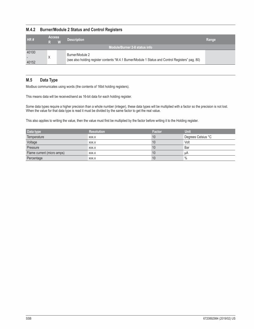
SSB 6720892984 (2019/02) US
M .4 .2 Burner/Module 2 Status and Control Registers
HR # Access Description RangeR WModule/Burner 2-8 status info
40100 - 40152
X Burner/Module 2 (see also holding register contents “M.4.1 Burner/Module 1 Status and Control Registers” pag. 80)
M .5 Data TypeModbus communicates using words (the contents of 16bit holding registers).
This means data will be received/send as 16-bit data for each holding register.
Some data types require a higher precision than a whole number (integer), these data types will be multiplied with a factor so the precision is not lost. When the value for that data type is read it must be divided by the same factor to get the real value.
This also applies to writing the value, then the value must first be multiplied by the factor before writing it to the Holding register.
Data type Resolution Factor UnitTemperature xxx.x 10 Degrees Celsius °C Voltage xxx.x 10 VoltPressure xxx.x 10 BarFlame current (micro amps) xxx.x 10 μAPercentage xxx.x 10 %

6720892984 (2019/02) US SSB

SSB 6720892984 (2019/02) US

6720
8929
84 (2
019/0
2) U
S
United States and Canada
Bosch Thermotechnology Corp.50 Wentworth AvenueLondonderry, NH 03053Tel. 603-552-1100Fax 603-965-7581www.boschheatingandcooling.comU.S.A.
Bosch Thermotechnology Corp. reserves the right to make changes without notice due to continuing engineering and technological advances.