buckling of a pressurized hemispherical shell subjected to ... · where e is young’s modulus, n...
TRANSCRIPT

Buckling of a pressurized hemispherical shellsubjected to a probing force
Joel Marthelot1, Francisco Lopez Jimenez2, Anna Lee3, John W. Hutchinson4, Pedro M. Reis1,3
1Department of Civil and Environmental, Massachusetts Institute of Technology, Cambridge, MA 021392Ann and H.J. Smead Aerospace Engineering Sciences, University of Colorado, Boulder, CO 80309
3Department of Mechanical Engineering, Massachusetts Institute of Technology, Cambridge, MA 021394School of Engineering and Applied Sciences, Harvard University, Cambridge, MA 02138
We study the buckling of hemispherical elastic shells sub-jected to the combined effect of pressure loading and a prob-ing force. We perform an experimental investigation usingthin shells of nearly uniform thickness that are fabricatedwith a well-controlled geometric imperfection. By systemat-ically varying the indentation displacement and the geome-try of the probe, we study the effect that the probe induceddeflections have on the buckling strength of our sphericalshells. The experimental results are then compared to finiteelement simulations, as well as to recent theoretical predic-tions from the literature. Inspired by a nondestructive tech-nique that was recently proposed to evaluate the stability ofelastic shells, we characterize the nonlinear load-deflectionmechanical response of the probe for different values of thepressure loading. We demonstrate that this nondestructivemethod is a successful local way to assess the stability ofspherical shells.
1 Introduction:Shell buckling has long been a canonical problem in
the structural mechanics community, with a remarkable andlongstanding history. As pointed out by Koiter more thanfifty years ago [1, 2], the critical buckling load of a shellstructure is highly sensitive to small imperfections. Indeed,the buckling load, pmax, measured in experiments (see Fig. 1in Ref. [3] for a summary of historical data) can be as low as20% of the classical prediction for spherical shell bucklingderived by Zoelly [4] in 1915:
pc =2E√
3(1−ν2)
( tR
)2, (1)
where E is Young’s modulus, ν is Poisson’s ratio, R and t theradius and thickness, respectively, of the shell. The knock-down factor, κ= pmax/pc, can then be defined as the ratio be-tween experimental measurements and the classical predic-tion of the critical buckling pressure. Due to the extreme sen-
sitivity of the buckling pressure to initial imperfections, prac-tical designs of curved shells have traditionally been madeusing empirical knockdown factors, based on large datasetsof buckling experiments [5]. We do not seek here to per-form an extensive survey of the vast, technical, and some-times convoluted prior literature on thin shell buckling. In-stead, we direct the interested reader to the recent papers byJohn Hutchinson and Michael Thompson [6, 7], where thisthematic is covered in detail.
In work of our own [3,8], we have recently demonstratedthat the critical buckling load of spherical shells observedin precision experiments can be accurately and deterministi-cally predicted by both Finite Element Modeling (FEM) anda reduced shell theory model. These experiments leverageda previously developed technique based on a viscous coatingmechanism [9] to fabricate thin polymeric shells with signif-icant flexibility and versatility in controlling the underlyingparameters. In particular, this experimental protocol yieldsthin elastic shells of nearly constant thickness, in a rapid, ver-satile and precise manner. Moreover, this technique offersthe possibility of introducing designed and well-controlledgeometric defects that are ‘frozen’ at the time of fabrication.By combining experiments with both FEM and a reducedshell theory, we showed that quantitatively predictive rela-tions can be established between the knockdown factor of anelastic shell and the geometry of the defect(s) that it contains.Nonetheless, a detailed a priori knowledge of the geometri-cal imperfections of the shell is still needed in order to pre-dict the stability of such a structure. In an attempt towardscircumnavigating this requirement, a novel nondestructiveframework has recently been proposed to probe the stabil-ity of uniformly compressed cylindrical shell [10–12] andspherical shells [13]. The basis of this approach is to mea-sure the relationship between the nonlinear deflection of anelastic shell that was initially compressed close to its work-ing load, by subjecting it to a point indentation force, whichhereon we shall refer to as probing force. The variation of theforce measured by the probe with respect to the indentationdisplacement curve at various levels of compression encodes
Published in J. Appl. Mech (2017) 84 (12) 121005.

the characteristics of the stability of the structure.Here, we study the effect of a probing force applied to
a pressurized spherical shell containing a well-defined geo-metric imperfection. We perform two different sets of ex-periments, in which the sequential order of the external pres-sure and the point-load probing is reversed. First, we applya probing displacement and then reduce the pressure withinthe shell until it buckles. In this case, the indentation inducesa local deformation of the shell. By predicting the shell de-formation with FEM, we explore the sensitivity of the knock-down factor to different amplitudes of the probe-induced de-flection. In the second set of experiments, the sequence isreversed by first reducing the pressure within the shell andthen applying a probing displacement until the shell buck-les. Naturally, due to the elasticity of the shell, the bucklingstates of the two shells are fundamentally connected, but thetwo experimental procedures are different and more impor-tantly, as will be seen, a different set of experimental datacan be measured in each case.
We also chose to use different types of loading systemsfor applying the pressure to the shell in the two cases men-tioned above. When the pressure is applied first, a systemwas devised to impose a prescribed pressure (pressure con-trol). On the other hand, when the probing force is appliedfirst, the compliance of the system applying the pressure issignificantly stiffer, such that it is closer to a system withprescribed volume change (volume control). While the ad-vanced post-buckling behavior of the shells under the twotypes of pressure loading is very different (complete collapseunder prescribed pressure and formation of a stable dimplebuckle under prescribed volume change), the pressure com-pliance has very little effect on the buckling condition it-self [13–15]. Following the work of Thompson and Hutchin-son [13], and supported by our own experiments and FEMsimulations, we demonstrate that the combination of pneu-matic loading, together with the compressive indentationloading, is a successful local strategy to non-destructivelyprobe the mechanical behavior of the shell. We highlighta parallel effort by Emmanuel Virot, Shmuel M. Rubinstein(Harvard University), Tobias Kreilos and Tobias Schneider(EPFL) on the stability of cylindrical shells set to variouslevels of axial compression, and probed by a point-load toobtain force-displacement curves [12]. By contrast, through-out our current study, we shall focus exclusively on hemi-spherical shells.
Our paper is organized as follows. First, we describe ourexperimental technique to fabricate thin elastomeric shellscontaining controlled geometrical imperfections (Sec. 2).We then introduce the methods for our finite element simula-tions (Sec. 3). In Sec. 4, we measure the buckling strength ofthe shells under combined pressure loading and a compres-sive point force. We explore the influence of the geometry ofthe defects in the shell, as well as the radius of the indenter,on the critical buckling pressure. The mechanical behaviorof the shell is then characterized under dead control pres-sure with a probe under controlled displacement (Sec. 5).Finally, we explore the influence of the angle between thecenter of the dimple imperfection and the direction of the
applied probing force on the stability of the shell (Sec. 6).
2 Experimental methods:In this section, we detail the rapid prototyping technique
used to produce the elastomeric shells and the experimentalsetup used to fabricate shells with a single dimple-like de-fect at its pole. We then present the experimental apparatusused to load the hemispherical shell, and describe the proto-col followed to measure the critical buckling pressure. Theexperimental process is outlined in the schematic diagram ofFig. 1a,b. Shells containing one precise frozen defect wereproduced by coating the inner side of a deformed mold in-dented by a flat plate (Fig. 1a). Upon curing, the preciselyimperfect thin elastic shell is probed by an indenter and theeffect of the probing displacement on the buckling pressureand the nonlinear response of the probe on the initially com-pressed shell are investigated (Fig. 1b).
2.1 Fabrication of shells containing a controlled geo-metric defect:
The thin elastic shells tested in all of our experimentswere fabricated using a previously developed technique [9].A hemispherical mold (radius R = 24.85 mm, machinedout of polyacetal through CNC milling) was coated witha silicone-based polymer solution (VPS, VinylpolysiloxaneElite Double 32, Zhermack). The VPS solution was mixedwith a ratio of 1:1 in weight of base to curing agent, for 10 sat 2000 rpm (clockwise), and then 10 s at 2200 rpm (counter-clockwise). The drainage flow produces a lubrication film onthe mold (Fig. 1a). Upon curing of the polymer, one obtainsan elastic shell of nearly constant thickness (t = 230 µm) thatcan then be readily peeled from the mold. The Young’s mod-ulus of cured VPS was measured to be E = 1.255MPa andits Poisson’s ratio was assumed to be ν = 0.5.
To fabricate precisely imperfect thin elastic shells (i.e.,shells containing a well-defined geometric imperfection),we use a second technique (itself a modification of that ofRef. [9] mentioned above), which we had introduced to in-vestigate the effect of the imperfection amplitude on the crit-ical buckling load [3]. We coated the inner side of a thickhemispherical shell of thickness tmold = 975 µm, used as amold, which was indented by a flat plate attached to a uni-versal testing machine. While holding the indentation con-stant, the polymer cured inside the deformed mold, therebyimposing an initial defect amplitude, δ, of the imperfectshell (Fig. 1a). Our previous study [9] showed that this pro-cedure leads to a single dimplelike defect that is localizednear the shell pole. In these experiments, to precisely setthe initial amplitude of the defect δ, we calibrated the load-displacement relation of the mold and imposed a displace-ment of the flat plate with the Instron machine until a specificvalue of the load was reached. The defect amplitude δ wasdefined as the distance between the position where the platecontacts the mold (characterized by a nonzero value of theload) and the position where the target load was reached. Theexcess of draining polymer naturally accumulates at the base

of the shell, making the hemispherical shell air tight. Theshape of the dimple is self-selected by the deformation of theouter elastic mold under indentation and can be predicted byFEM simulations as described in Ref. [3] and briefly recalledin Sec. 3. Note that in our experiment the dimple imperfec-tion is always located at the pole of the hemisphere. Note thatin our experiment the dimple imperfection is always locatedat the pole of the hemisphere. However, the insensitivityof the dimple location on the critical pressure was recentlydemonstrated via with non-axisymmetric numerical analy-sis [16], which points to the localized nature of the dimple.We do not expect that changing the position of the center ofthe dimple would affects our results on the buckling process,as long as the dimple is not too near the clamped equator.
2.2 Experimental apparatus:In Fig. 1, we show a schematic diagram and a photo-
graph of our experimental apparatus. An elastomeric hemi-spherical shell was mounted onto an acrylic plate and sealedby subsquently injecting a polymer layer through a circu-lar channel in contact with the base of the hemisphericalshell, such that no residual stresses were imparted onto theshell after clamping its equatorial boundary. The shell wasthen connected to both a syringe pump (NE-1000, New EraPump Systems, Inc.) and a pressure sensor (MPXV7002,NXP semiconductors). The pressure under the shell was setby extracting a given volume of air with the syringe pump,while simultaneously applying an indentation using an uni-versal testing machine (5943, Instron, Norwood, MA). Theacrylic plate was then fixed onto a multiangle mount [17](410 Junior Geared Head, Manfrotto). We define the angleθ as the angle between the direction that is perpendicular tothe center of the dimple imperfection and the direction of theindentation force (see Fig.1b).
The shell was indented at his apex by a rigid sphericalRockwell C diamond indenter (radius a = 200 µm, CSM).The force was measured by a universal testing machine(5943, Instron), under imposed displacement conditions.The additional deflection ξ = wpole−w0 corresponds to thevariation of the position of the shell apex after and beforethe application of the load. Following Hutchinson [18], wedefine the dimensionless additional pole deflection by:
ξ =√
1−ν2 ξ
t. (2)
The point of contact between the probe and the shell corre-sponds to ξ = 0. In Sec. 4 and Sec. 5, the probe force actsat the center of the dimple imperfection (θ = 0), while nonaxisymetric cases are explored experimentally in Sec. 6.
In the experiments, we considered four defect ampli-tudes (δ = 0.26,0.40,0.60,0.85), where δ = δ/t is the de-fect amplitude normalized by the shell thickness. In Sec. 4,the shells were first probed with an indenter, and then de-pressurized until buckling occurred. For each shell, we sys-tematically varied the additional pole deflection in the range0 ≤ ξ ≤ 15. While monitoring the internal pressure of the
Pressure
sensor
Syringe
pump
Labview data
aquisition
Sample
Multiangle mount
Indenter
Instron universal
testing machine
t
β
δ
ξ θR
a(b)
(c)
δ(a)
Fig. 1. (a) Schematic diagram of the fabrication of a shell with afrozen dimple imperfection with a defect amplitude δ. (b) Sketch ofthe precisely imperfect shell of thickness t , characterized by a defectamplitude δ and a defect angle β. The shell is probed by a inden-ter of radius a at an angle θ imposing a additional deflection ξ. (c)Photograph of the experimental setup used to measure the pressurevariation of a thin hemispherical shells, onto which we impose a setindentation displacement using a universal testing machine (Instron).
shell, its inner volume was decreased by extracting air at theimposed constant flow rate of 0.1 ml/min; a value that wassmall enough such that the loading conditions could be con-sidered as quasi-static. The net external pressure acting onthe shell is defined as p> 0. The shell buckles when the pres-sure reaches the experimental bucking load pmax, defined atthe maximum pressure difference between the atmosphericpressure and the internal pressure. All of the experimentswere performed with an indenter of radius a = 200 µm, withthe exception of Sec. 4.3, where the effect of the indenterradius, a, on the knockdown factor is also studied.
For the experiments in Sec. 5, the system was held ata constant level of depressurization po, and the shells werethen probed with the indenter. The dimensionless pole de-flection at which the shell collapses is noted as ξ0. A reser-voir with a large volume of air (V = 110L) was used as abuffer to impose a dead control pressure condition by min-imizing the variation of pressure when the indentation wasapplied. A given volume of air inside the shell was extractedat an imposed constant flow rate of 0.1 ml/min, until the pres-sure reaches po a fraction of pc. The variation of po dur-

ing the indentation phase was kept smaller than 5% thanksto the large volume of the reservoir. The non-linear force-displacement curve of the indentation was recorded for asystematic variation of po/pc, between 0 and 0.55. The dis-placement of the indenter (rigid probe) was controlled andmoved at a constant velocity (0.025 mm/s), between ξ = 0and 8. The corresponding reaction force, F , was recordedfor six independent runs with identical conditions (e.g., thesame value of po/pc). The force signal was of the order ofa few mN and the experimental noise-to-signal ratio for asingle run could be as large as 30%. The irregular fluctua-tions of the force signal due to the experimental noise tendto cancel out by averaging the six independent, but otherwiseidentical, runs. After averaging, this experimental noise wasreduced to 12%.
3 Simulation methods:In parallel to the experiments described above, we also
performed computer simulations using the commercial FiniteElement Modeling (FEM) package Abaqus/Standard. Theshells are modeled as hemispheres clamped at the equator.Two different set of FEM simulations were performed. (i)For a direct comparison with the experimental process, wecomputed the profile of the imperfect shell under indenta-tion and calculated the buckling load under live pressure. InSec. 3.1 and Sec. 4.1, we model the full fabrication process,mimicking the experimental procedure in FEM. (ii) For asystematic exploration of the effect of the shape of the im-perfection on the buckling load, we assumed a generic shapeof the dimple. In Sec. 3.2 and Sec. 4.2, we study a Gaussiandimple and perform a parametric exploration of the influenceof the defect shape on the buckling load. Both set of simula-tions assume axisymmetry to reduce the computational cost,since it has been shown that non-axisymmetric bifurcationsonly take place far into the postbuckling regime [7, 19, 20].
3.1 Mimicking the experimental procedure in the FEMsimulations:
In the experiments, the precise shape of the initial dim-ple is self-selected by the elastic deformations resulting fromthe fixed indentation of the mold by a rigid plate, at the timeof the fabrication process, during curing. In the simulations,to predict the shape of the engineered defect, we used thenumerical method that we had developed and experimen-tally verified previously to study the effect of an imperfectshell on the critical buckling pressure of the shell [3, 8]. Theouter elastic mold was modeled as an incompressible Neo-Hookean solid, with reduced hybrid axisymmetric elementsCAX4RH, and a thickness tmold = 975 µm. The indentationplate was modeled as a rigid flat surface using RAX2 ele-ments. For each defect amplitude δ, the indentation loadingof the mold was computed by imposing the vertical displace-ment of the plate with frictionless contact between the freesurface. The position of the inner surface of the mold wasextracted and assumed to be equal to the outer surface of thefabricated imperfect shell. The defect amplitude of the de-
fect and the corresponding profile computed from FEM hadpreviously been shown to be very close to the shape of thedefect extracted experimentally [3]. The imperfection is lo-calized near the pole.
For the current study, after determining the shape of theengineered defect, an additional step was needed to intro-duce the indentation loading of the shell. This indentationwas modeled as an indenter of radius a with frictionless con-tact between the free surface. Both shell and indenter weremodeled again as incompressible Neo-Hookean solid, usingreduced hybrid axisymmetric elements CAX4RH. The stiff-ness of the indender was taken to be 1000 times that of theshell. The loading was modeled as a live pressure on theouter surface of the structure. Given the unstable postbuck-ling behavior of the shells, the simulations used the Riksmethod [21], which simultaneously solves for loads and dis-placements. This way, the progress of the simulation withthe arc-length of the load-displacement curve could be mea-sured.
Following the experimental values, the ratio of radius tothickness of the shells studied numerically was varied in therange 100 ≤ R/t ≤ 113. The discretization in the radial di-rection used 10 elements, and 1000 in the angular direction.These values are chosen according to the convergence anal-ysis performed for previous studies [3, 8, 22].
Finally, and in order to further emphasize the differencebetween the effects of an initial geometric imperfection andthe indentation, we performed an additional set of simula-tions in which the deflection due to the indentation was cal-culated, and applied to the shell as an initial defect, i.e. withno stress. To differentiate this imperfection from the initialdimple present in the simulations with indenters, we referto it as a frozen defect. In this case an initial simulation isperformed to establish the shape under indentation, and thisgeometry is used to define a new shell, whose buckling loadis calculated in a simulation where the only load present isthe live pressure.
3.2 Exploration of a dimple with generic shape:After directly contrasting the simulations results to the
experiments (results in Sec. 4.1), we then performed a morethorough exploration of the parameters using the simulationsalone. For both simplicity and generality, we assumed a sim-ple functional form for the initial shape of the geometric im-perfections. The defects were directly introduced in the meshas a normal displacement of the middle surface, with the pro-file of a Gaussian dimple:
wI =−δe−(β/β0)2, (3)
where β is the angular measure from the pole, and δ and β0are parameters that control the depth and angular width of thedefect, respectively. The rest of the mesh was then definedassuming constant thickness t perpendicular to the middlesurface. To account for the variation of the angular width ofthe imperfection, β0, we introduced the geometric parameter

following [23]:
λ ={
12(1−ν2)}1/4
√Rt
β0. (4)
Our previous results [3, 8] confirmed that λ is indeed an ap-propriate and effective single geometric parameter to charac-terize how a frozen defect dictates the imperfection sensitiv-ity of our shells. While the Gaussian dimple is only an ap-proximation of the experimental self-selected shape obtainedexperimentally by indenting the mold with a plate, we findthat the best fit to the shape predicted by FEM for the spe-cific mold thickness used in the experiments is obtained withβ0 = 10.8◦.
4 Buckling strength of hemispherical shells under com-bined pneumatic and point loading:We start our investigation by following the methodology
introduced in Sec 2.2 and Sec.3.1 to explore and comparethe experimental and numerical results. The shells were firstprobed with an indenter, and then depressurized until buck-ling occurred. The point force is applied at the apex of theimperfect shell at the location of the largest defect (θ = 0).
4.1 Buckling strength of controlled imperfect shell sub-mitted to a point force:
In Fig. 2, we plot the variation of the knockdown factorκd as a function of the dimensionless indentation of the probeξ. In the experiments, four shells were fabricated includingdefects of different amplitudes (δ = 0.26, 0.40, 0.60, 0.85).The initial geometric imperfection controls the knockdownfactor without indentation, κd0, and, as long as the exact ge-ometry of the imperfection is appropriately included, can beaccurately predicted by simulations and theory [3]. Whenthe shell is indented, we observe three distinct regimes on theknockdown factor with increasing values of ξ: (i) insensitiv-ity at small values of indentation (0 < ξ . 1); (ii) sharp de-crease in an intermediate regime (1. ξ. 5); and (iii) plateauat large indentation values (5 . ξ < 15).
(i) At small indentations (0 < ξ . 1), we find that theextent of indentation, ξ, has no effect on the critical bucklingpressure, such that κd ∼ κd0. The extent of this initial plateaudepends on the amplitude of the defect of the shell. Shellsincluding defects with larger amplitudes are less sensitive tosmall indentations. This effect will be numerically exploredin more detail in Sec. 4.2.
(ii) In the intermediate regime (1 . ξ . 5), an indenta-tion ξ of up to a few thicknesses translates into a significantdrop of the critical buckling load. In this regime, the pointload induces a deflection that significantly affects the shapeand the amplitude of the initial imperfection. The sharp dropof the knockdown factor with indentation amplitude is a sig-nature of the high sensitivity of the stability of the shell tosmall probe-induced deflections. This feature is particularlysignificant for shells that possess a small initial imperfection
(e.g., δ = 0.26, blue points in Fig. 2), for which the knock-down factor is decreased to 0.3κd0.
(iii) In the limit of large indentation (5 . ξ < 15), weobserve a lower bound for the knockdown factor. We foundthat the critical pressure is independent of both the level ofindentation and the initial amplitude of the defect. The latteris screened by the deflection of the shell imposed by the in-denter. Note that this lower bound is different from the previ-ously studied numerical bound for frozen defects [8] (wherethe lower bound was shown to depend solely on the shell ra-dius to thickness ratio and the angular width of the frozendefect). This comparison provides evidence for the differ-ence between the cases of direct indentation and the frozendefect, which is further discussed below.
0 2 4 6 8 10 12
0
0.1
0.2
0.3
0.4
0.5
0.6
0.7
0.8
0.9
1
Fig. 2. Knockdown factor, κd , versus indentation depth, ξ. Inthe experiments (closed symbols), the shells (R=24.9 mm, t=220-250 µm) were fabricated with initial normalized defect amplitude δ =0.26,0.40,0.60,0.85. The solid lines represent simulations byFEM for the corresponding defect profile. The dashed lines are thenumerical prediction for a frozen defect with the same geometry.
The results from finite element simulations are also plot-ted in Fig. 2 (solid lines), aloing with the experimental re-sults, for the same four defect amplitudes of the experiments.The numerical results for the case of a perfect shell withoutan initial frozen imperfection (δ = 0) is also included in theplot, which cannot be compared to experiments because ofthe inherent small material defects of the shell fabricationprocess that lead to the unavoidable initial knockdown factorof κd ≈ 0.75. Otherwise, there is excellent agreement be-tween experiments and simulations. Specifically, the FEMdata confirm the three regimes described above. This quan-titative match further emphasizes the predictive value of ourdescription of the sensitivity of shell buckling to geometricimperfections, which was already observed in our previousstudy [3], albeit with the frozen imperfections then, as op-posed to the combined pressure loading and probing forcenow. In particular, our current experimental setup is less de-

pendent to the most difficult experimental challenge (the fab-rication of the imperfect shells with frozen defect by a smallindentation of the mold δ) to rely on a much more straight-forward deformation process by directly indenting the shell(with comparatively large probe displacement ξ).
In Fig. 2, the numerical prediction for the direct inden-tation of the shell (solid line) is also contrasted with the oneobtained for the equivalent frozen defect with the exact samegeometry but no residual stresses (dashed line). The vari-ation of the knockdown factor for the frozen defect is sig-nificantly sharper that the one predicted for the direct in-dentation, which further highlights the difference betweenfrozen geometric imperfections and direct indentation, sincethe later induces a non-equilibrated stress field in addition tothe deflection of the shell.
4.2 Insensitivity of shell buckling to the defect geometryat small indentations
Having experimentally characterized the evolution ofthe knockdown factor with indentation and validated our nu-merical method, we now quantify more extensively the effectof the defect geometry on the critical pressure insensitivitywithin the small indentation; the regime (i) listed in the pre-vious section. We focus on a more generic shape for thedimple, as introduced in Eq. (3). In particular, we focus onthe angular width of the defect β0 on the edge of the plateau,ξc.
In Fig. 3(a), we plot the variation of the knockdownfactor versus the indentation depth ξ for a Gaussian dim-ple with λ = 3, indented by a probe of radius a = 200 µm.We simulated shells with eleven different initial defects ofamplitudes that were distributed in the range 0.05 ≤ δ ≤ 1,equally distributed between 0.1 and 1 with incremental stepsof ∆δ = 0.1. Again, we recover the three characteristicregimes described in Sec. 4.1. The knockdown factor isfirst insensitive to the probe displacement (i), then decreasessharply (ii) and, finally, reaches a lower-bound master curve(iii).
From the κd(ξ) data in Fig. 3(a), we can now define thenondimensional indentation ξc, where the knockdown factorreaches 95% of its value at zero indentation κd0 (highlightedwith circles in Fig. 3(a)), characterizing the edge of the initialplateau. In Fig. 3(b), we plot the variation of ξc as a func-tion of the amplitude of the initial geometric imperfection,δ, for five geometric imperfections, λ = {2.615, 3, 4, 5, 10}.The chosen value of λ = 2.615 is the critical λ for δ = 1, i.e.the geometric parameter that results in the largest reductionof the critical buckling load for an initial defect amplitudeof one shell thickness. While a small indentation has an im-mediate effect on a shell fabricated with a dimple of smallamplitude, shells that contain a large initial imperfection areless sensitive to small indentations applied at the position ofthe defect. Note that under all conditions of indentation, theknockdown factors of shell that present an initial larger de-fect remain smaller, whatever the value of ξ. The criticaldisplacement depends strongly on the original defect geom-etry characterized by λ. Wider initial defects (large value of
0.05
0.1
0.2
0.3
0.4
0.5
0.6
0.7
0.8
0.9
1.0
(a)
(b)
0 0.2 0.4 0.6 0.8 1
0
0.5
1
1.5
2
2.5
3
0 0.5 1 1.5 2 2.5 3 3.5 4
0
0.1
0.2
0.3
0.4
0.5
0.6
0.7
0.8
0.9
1
Fig. 3. (a) Knockdown factor, κd , versus the indentation depth,ξ, calculated from FEM, for a generic Gaussian dimple with a pro-file defined by Eq. (3). The radius-to-thickness ratio of the shellsis R/t = 100, containing Gaussian dimples with λ = 3 and δ =[0.05, 0.1, 0.2, . . . , 0.9, 1], distributed between 0.1 and 1 by stepof 0.1. (b) Critical displacement, ξc, corresponding to a knockdownfactor of 0.95κd0 versus the amplitude of the initial imperfection,δ, for shells with λ = [2.615, 3, 4, 5, 10] and an indenter radiusa = 200 µm.
λ) tend to be more sensitive to small values of the indenta-tion, even with large values of the amplitude of the initialimperfection, δ.
4.3 Effect of the probe geometry on the critical bucklingload:
The influence of the probe geometry on the critical buck-ling load is important for design consideration for real struc-tures in noisy operational environments. In Fig. 4(a), we re-port the variation of the knockdown factor with the probedisplacement, for four different indenter geometries (definedby their radius of curvature).The shell used for these experi-ments had an initial normalized amplitude of δ = 0.62. The

effect of the shell geometry is rather limited. We observe aslight decrease of the knockdown factor for indenters witha large diameter (a = 22 mm and a plate), at large indenta-tion depths (ξ > 3). Those results are confirmed by the FEMsimulations performed for shells containing Gaussian dim-ples (with λ = 2.615 and R/t = 100), which exhibit a smallvariation of the knockdown factor with the geometry. Theknockdown factors computed with an indenter of radius a =0.22, 2 and 4 mm are identical within 1%. In Fig. 4(b), weplot the computed knockdown factor, κd(a = 22), with anindenter of radius a = 22 mm normalized by κd(a = 0.22)computed with an indenter of radius a = 0.22 mm. The max-imum effect of the indenter geometry is small, with a max-imal decrease of the knockdown factor by 7%, observed fora small initial frozen defect (δ = 0.05) and a moderate probedisplacement (ξ = 3).
5 Probing imperfect shells under dead pressure:Shifting to the second part of our study, we now focus
on an experimental system comprising a shell that is loadedwith a constant external pressure (dead control pressure), po,as described in Sec. 2.2, above. An indentation force, F , isthen exerted under imposed displacement, ξ. In Sec. 5.1, westart by using the indenter as a probe to explore the non-linearresponse of the uniformly pressurized shell. We character-ize the maximum load, Fmax, that the shell can carry beforebuckling occurs, at various levels of depressurization po/pc.In Sec. 5.2, we then compute the work done by the indenterrequired to reach the buckling state, which corresponds tothe energy barrier that the probe must overcome for bucklingat the prescribed value of the depressurization. In Sec. 5.3,we show how this quantity can be used as a non-destructivetechnique to experimentally test the amplitude of the defectand to assess the stability of the shell. We first study a shellthat does not contain any engineered defect and is the closestto a perfect shell that we can attain in our experiments (inSec. 5.1 and Sec. 5.2). We then present results for a shellcontaining a well-defined geometric defect and study its ef-fect on the destabilizing role of the point load (in Sec. 5.3).
5.1 Maximum carrying load of a perfect shell:In Fig. 5, we plot the measured probe force, FR/(2πD)
as a function of the deflection imposed by the indenter at thepole of the shell, which is uniformly pressurized. In this plot,the various levels of depressurization, po/pc, are color-coded(see legend); 0 ≤ po [Pa] ≤ 66 is varied in steps of ∼5 Pa,while the dimensionless probe displacement is imposed inthe range 0≤ ξ≤ 8.
The passive probing force F has been normalized by thebending rigidity of the shell, D = Et3/12(1−ν2), to read:
F =FR2πD
. (5)
Obtain the data in Fig. 5, involved averaging the probingforce signals for six independent, but otherwise identical, ex-perimental runs at each level of depressurization to increase
0 2 4 6 8 10 12
0
0.1
0.2
0.3
0.4
0.5
0.6(a)
(b)
0 1 2 3 4 5 6 7 8 9
0.9
0.95
1
1.05
0.05
0.1
0.2
0.3
0.4
0.5
0.6
0.7
0.8
0.9
1.0
Fig. 4. Experimental knockdown factor, κd , versus indentationdepth, ξ, for four geometries of the indenter characterized bytheir curvature radius (a = [0.2, 4, 22, ∞]mm) for the same shell(R=24.9 mm, t=210 µm) fabricated with an initial normalized defectamplitude δ = 0.62. (b) Knockdown factor, κd(a = 22), computedby FEM with an indenter of radius a=22 mm normalized by the knock-down factor, κd(a = 0.22) computed considering an indenter of ra-dius a = 0.22 mm for a generic Gaussian dimple with a profile de-fined by Eq. (3). The radius-to-thickness ratio is R/t = 100 and theshells contain Gaussian dimples with λ = 2.615.
the experimental signal-to-noise ratio. Note that for largevalues of the depressurization, the measured forces are closeto the limit of the resolution of our force sensor (Instron Nor-wood, MA 2530-10N) and the signal-to-noise ratio on theforce measurement is lower. The test is repeated at 11 dif-ferent constant levels of external compression po normalizedby pc. For po/pc = 0 (upper curves of the plot, in dark blue),the indentation process is always stable; the force F increasesmonotonically, and there are two regimes at small and largeindentations. In the limit of small indentation (with respectto the shell thickness, ∆w < t), the force is described by thelinear Reissner’s rigidity [17, 24, 25]. At larger values of theindentation, we observe a nonlinear shell deflection as de-
scribed by Pogorelov [26, 27].When the level of depressurization of the shell is in-
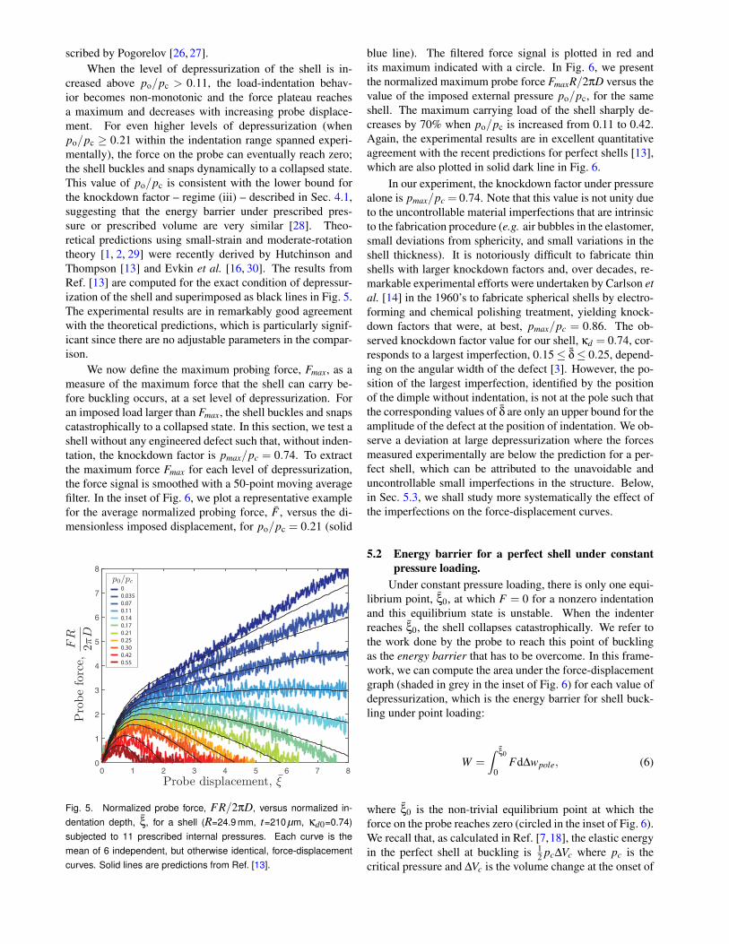
creased above po/pc > 0.11, the load-indentation behav-ior becomes non-monotonic and the force plateau reachesa maximum and decreases with increasing probe displace-ment. For even higher levels of depressurization (whenpo/pc ≥ 0.21 within the indentation range spanned experi-mentally), the force on the probe can eventually reach zero;the shell buckles and snaps dynamically to a collapsed state.This value of po/pc is consistent with the lower bound forthe knockdown factor – regime (iii) – described in Sec. 4.1,suggesting that the energy barrier under prescribed pres-sure or prescribed volume are very similar [28]. Theo-retical predictions using small-strain and moderate-rotationtheory [1, 2, 29] were recently derived by Hutchinson andThompson [13] and Evkin et al. [16, 30]. The results fromRef. [13] are computed for the exact condition of depressur-ization of the shell and superimposed as black lines in Fig. 5.The experimental results are in remarkably good agreementwith the theoretical predictions, which is particularly signif-icant since there are no adjustable parameters in the compar-ison.
We now define the maximum probing force, Fmax, as ameasure of the maximum force that the shell can carry be-fore buckling occurs, at a set level of depressurization. Foran imposed load larger than Fmax, the shell buckles and snapscatastrophically to a collapsed state. In this section, we test ashell without any engineered defect such that, without inden-tation, the knockdown factor is pmax/pc = 0.74. To extractthe maximum force Fmax for each level of depressurization,the force signal is smoothed with a 50-point moving averagefilter. In the inset of Fig. 6, we plot a representative examplefor the average normalized probing force, F , versus the di-mensionless imposed displacement, for po/pc = 0.21 (solid
0 1 2 3 4 5 6 7 8
0
1
2
3
4
5
6
7
8
0
0.035
0.07
0.11
0.14
0.17
0.21
0.25
0.30
0.42
0.55
Fig. 5. Normalized probe force, FR/2πD, versus normalized in-dentation depth, ξ, for a shell (R=24.9 mm, t=210 µm, κd0=0.74)subjected to 11 prescribed internal pressures. Each curve is themean of 6 independent, but otherwise identical, force-displacementcurves. Solid lines are predictions from Ref. [13].
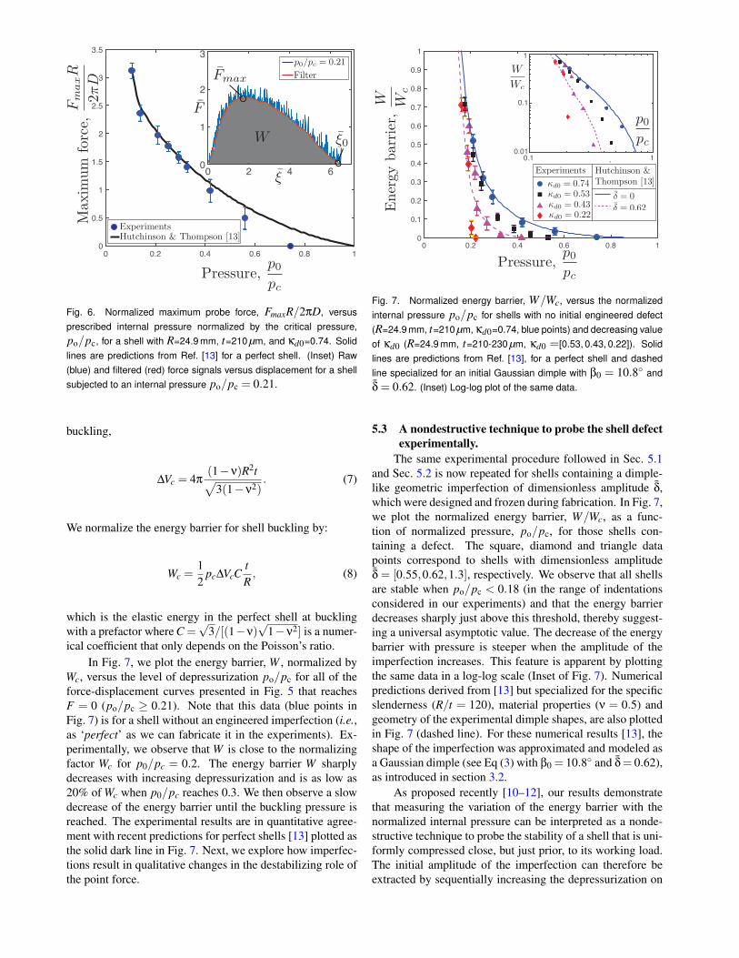
blue line). The filtered force signal is plotted in red andits maximum indicated with a circle. In Fig. 6, we presentthe normalized maximum probe force FmaxR/2πD versus thevalue of the imposed external pressure po/pc, for the sameshell. The maximum carrying load of the shell sharply de-creases by 70% when po/pc is increased from 0.11 to 0.42.Again, the experimental results are in excellent quantitativeagreement with the recent predictions for perfect shells [13],which are also plotted in solid dark line in Fig. 6.
In our experiment, the knockdown factor under pressurealone is pmax/pc = 0.74. Note that this value is not unity dueto the uncontrollable material imperfections that are intrinsicto the fabrication procedure (e.g. air bubbles in the elastomer,small deviations from sphericity, and small variations in theshell thickness). It is notoriously difficult to fabricate thinshells with larger knockdown factors and, over decades, re-markable experimental efforts were undertaken by Carlson etal. [14] in the 1960’s to fabricate spherical shells by electro-forming and chemical polishing treatment, yielding knock-down factors that were, at best, pmax/pc = 0.86. The ob-served knockdown factor value for our shell, κd = 0.74, cor-responds to a largest imperfection, 0.15≤ δ≤ 0.25, depend-ing on the angular width of the defect [3]. However, the po-sition of the largest imperfection, identified by the positionof the dimple without indentation, is not at the pole such thatthe corresponding values of δ are only an upper bound for theamplitude of the defect at the position of indentation. We ob-serve a deviation at large depressurization where the forcesmeasured experimentally are below the prediction for a per-fect shell, which can be attributed to the unavoidable anduncontrollable small imperfections in the structure. Below,in Sec. 5.3, we shall study more systematically the effect ofthe imperfections on the force-displacement curves.
5.2 Energy barrier for a perfect shell under constantpressure loading.
Under constant pressure loading, there is only one equi-librium point, ξ0, at which F = 0 for a nonzero indentationand this equilibrium state is unstable. When the indenterreaches ξ0, the shell collapses catastrophically. We refer tothe work done by the probe to reach this point of bucklingas the energy barrier that has to be overcome. In this frame-work, we can compute the area under the force-displacementgraph (shaded in grey in the inset of Fig. 6) for each value ofdepressurization, which is the energy barrier for shell buck-ling under point loading:
W =∫
ξ0
0Fd∆wpole, (6)
where ξ0 is the non-trivial equilibrium point at which theforce on the probe reaches zero (circled in the inset of Fig. 6).We recall that, as calculated in Ref. [7,18], the elastic energyin the perfect shell at buckling is 1
2 pc∆Vc where pc is thecritical pressure and ∆Vc is the volume change at the onset of
0 0.2 0.4 0.6 0.8 1
0
0.5
1
1.5
2
2.5
3
3.5
0 2 4 60
1
2
3
Fig. 6. Normalized maximum probe force, FmaxR/2πD, versusprescribed internal pressure normalized by the critical pressure,po/pc, for a shell with R=24.9 mm, t=210 µm, and κd0=0.74. Solidlines are predictions from Ref. [13] for a perfect shell. (Inset) Raw(blue) and filtered (red) force signals versus displacement for a shellsubjected to an internal pressure po/pc = 0.21.
buckling,
∆Vc = 4π(1−ν)R2t√
3(1−ν2). (7)
We normalize the energy barrier for shell buckling by:
Wc =12
pc∆VcCtR, (8)
which is the elastic energy in the perfect shell at bucklingwith a prefactor where C =
√3/[(1−ν)
√1−ν2] is a numer-
ical coefficient that only depends on the Poisson’s ratio.In Fig. 7, we plot the energy barrier, W , normalized by
Wc, versus the level of depressurization po/pc for all of theforce-displacement curves presented in Fig. 5 that reachesF = 0 (po/pc ≥ 0.21). Note that this data (blue points inFig. 7) is for a shell without an engineered imperfection (i.e.,as ‘perfect’ as we can fabricate it in the experiments). Ex-perimentally, we observe that W is close to the normalizingfactor Wc for p0/pc = 0.2. The energy barrier W sharplydecreases with increasing depressurization and is as low as20% of Wc when p0/pc reaches 0.3. We then observe a slowdecrease of the energy barrier until the buckling pressure isreached. The experimental results are in quantitative agree-ment with recent predictions for perfect shells [13] plotted asthe solid dark line in Fig. 7. Next, we explore how imperfec-tions result in qualitative changes in the destabilizing role ofthe point force.
0 0.2 0.4 0.6 0.8 1
0
0.1
0.2
0.3
0.4
0.5
0.6
0.7
0.8
0.9
1
0.1 10.01
0.1
1
Fig. 7. Normalized energy barrier, W/Wc, versus the normalizedinternal pressure po/pc for shells with no initial engineered defect(R=24.9 mm, t=210 µm, κd0=0.74, blue points) and decreasing valueof κd0 (R=24.9 mm, t=210-230 µm, κd0 =[0.53, 0.43, 0.22]). Solidlines are predictions from Ref. [13], for a perfect shell and dashedline specialized for an initial Gaussian dimple with β0 = 10.8◦ andδ = 0.62. (Inset) Log-log plot of the same data.
5.3 A nondestructive technique to probe the shell defectexperimentally.
The same experimental procedure followed in Sec. 5.1and Sec. 5.2 is now repeated for shells containing a dimple-like geometric imperfection of dimensionless amplitude δ,which were designed and frozen during fabrication. In Fig. 7,we plot the normalized energy barrier, W/Wc, as a func-tion of normalized pressure, po/pc, for those shells con-taining a defect. The square, diamond and triangle datapoints correspond to shells with dimensionless amplitudeδ = [0.55,0.62,1.3], respectively. We observe that all shellsare stable when po/pc < 0.18 (in the range of indentationsconsidered in our experiments) and that the energy barrierdecreases sharply just above this threshold, thereby suggest-ing a universal asymptotic value. The decrease of the energybarrier with pressure is steeper when the amplitude of theimperfection increases. This feature is apparent by plottingthe same data in a log-log scale (Inset of Fig. 7). Numericalpredictions derived from [13] but specialized for the specificslenderness (R/t = 120), material properties (ν = 0.5) andgeometry of the experimental dimple shapes, are also plottedin Fig. 7 (dashed line). For these numerical results [13], theshape of the imperfection was approximated and modeled asa Gaussian dimple (see Eq (3) with β0 = 10.8◦ and δ= 0.62),as introduced in section 3.2.
As proposed recently [10–12], our results demonstratethat measuring the variation of the energy barrier with thenormalized internal pressure can be interpreted as a nonde-structive technique to probe the stability of a shell that is uni-formly compressed close, but just prior, to its working load.The initial amplitude of the imperfection can therefore beextracted by sequentially increasing the depressurization on
the shell and: (i) probing the load-displacement curve (witha minimum threshold slightly larger than zero for the forcesignal to avoid the catastrophic collapse of the structure);(ii) computing the corresponding energy barrier; and (iii) in-creasing the depressurization on the shell. The process is it-erated until the energy barrier reaches a set small fraction ofWc (for example 5%). The value of the corresponding inter-nal pressure po provides information on the initial amplitudeof the defect at the position of the probe.
6 Imposing a nonaxisymetric point-load on an imper-fect shell:So far, we have applied the point load at the same posi-
tion of the center of the largest frozen defect on the shell (i.e.,at the pole, by construction). In this section, we explore theeffect of probing away from the polar imperfection. We firstfocus on the buckling strength of the shell by applying theindentation and then depressurizing the shell until bucklingoccurs. We then turn to exploring the force-displacement be-havior of the probe under a given level of depressurization.The corresponding variation of the energy barrier as a func-tion of the angle at which the point-load is applied is crucialto understand the sensitivity of the nondestructive techniquedescribed in Sec. 5.3 to probe imperfect shells.
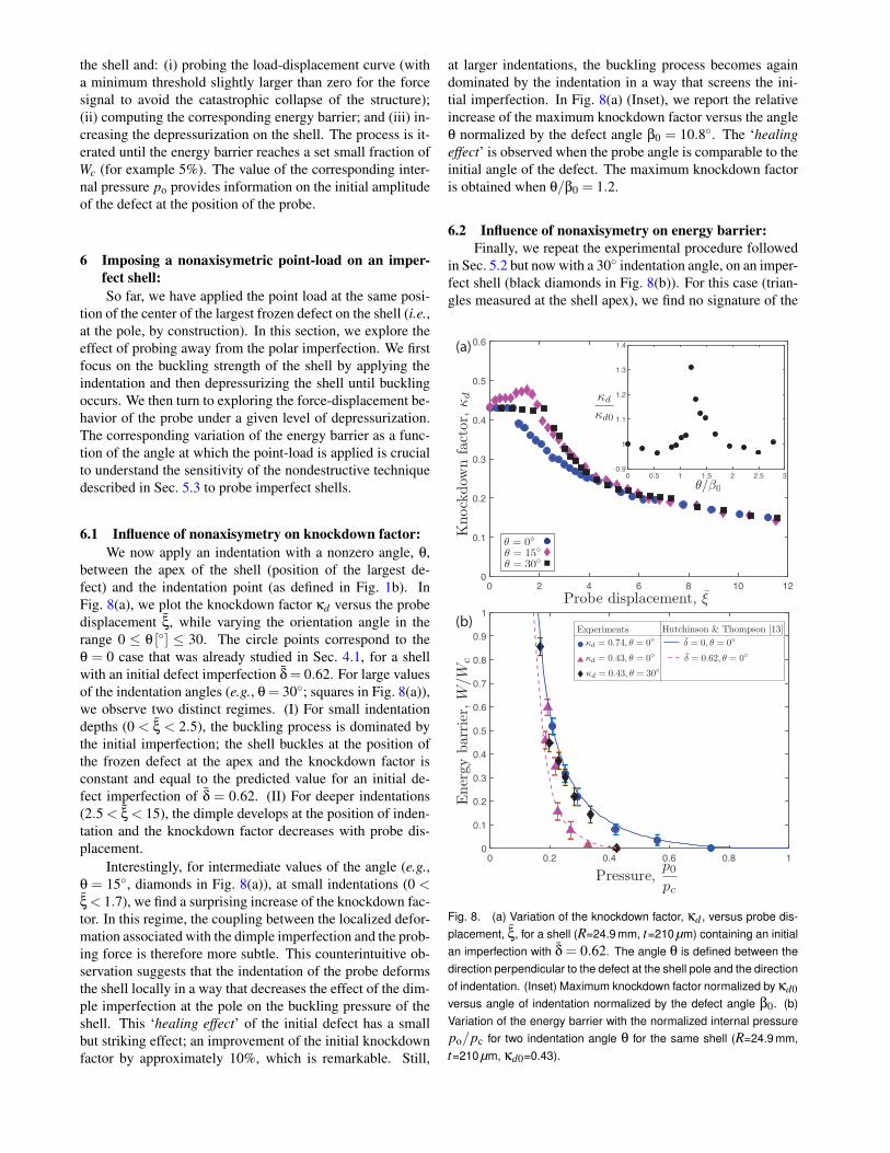
6.1 Influence of nonaxisymetry on knockdown factor:We now apply an indentation with a nonzero angle, θ,
between the apex of the shell (position of the largest de-fect) and the indentation point (as defined in Fig. 1b). InFig. 8(a), we plot the knockdown factor κd versus the probedisplacement ξ, while varying the orientation angle in therange 0 ≤ θ [◦] ≤ 30. The circle points correspond to theθ = 0 case that was already studied in Sec. 4.1, for a shellwith an initial defect imperfection δ = 0.62. For large valuesof the indentation angles (e.g., θ = 30◦; squares in Fig. 8(a)),we observe two distinct regimes. (I) For small indentationdepths (0 < ξ < 2.5), the buckling process is dominated bythe initial imperfection; the shell buckles at the position ofthe frozen defect at the apex and the knockdown factor isconstant and equal to the predicted value for an initial de-fect imperfection of δ = 0.62. (II) For deeper indentations(2.5 < ξ < 15), the dimple develops at the position of inden-tation and the knockdown factor decreases with probe dis-placement.
Interestingly, for intermediate values of the angle (e.g.,θ = 15◦, diamonds in Fig. 8(a)), at small indentations (0 <ξ < 1.7), we find a surprising increase of the knockdown fac-tor. In this regime, the coupling between the localized defor-mation associated with the dimple imperfection and the prob-ing force is therefore more subtle. This counterintuitive ob-servation suggests that the indentation of the probe deformsthe shell locally in a way that decreases the effect of the dim-ple imperfection at the pole on the buckling pressure of theshell. This ‘healing effect’ of the initial defect has a smallbut striking effect; an improvement of the initial knockdownfactor by approximately 10%, which is remarkable. Still,
at larger indentations, the buckling process becomes againdominated by the indentation in a way that screens the ini-tial imperfection. In Fig. 8(a) (Inset), we report the relativeincrease of the maximum knockdown factor versus the angleθ normalized by the defect angle β0 = 10.8◦. The ‘healingeffect’ is observed when the probe angle is comparable to theinitial angle of the defect. The maximum knockdown factoris obtained when θ/β0 = 1.2.
6.2 Influence of nonaxisymetry on energy barrier:Finally, we repeat the experimental procedure followed
in Sec. 5.2 but now with a 30◦ indentation angle, on an imper-fect shell (black diamonds in Fig. 8(b)). For this case (trian-gles measured at the shell apex), we find no signature of the
0 2 4 6 8 10 12
0
0.1
0.2
0.3
0.4
0.5
0.6
0 0.5 1 1.5 2 2.5 3
0.9
1
1.1
1.2
1.3
1.4(a)
(b)
0 0.2 0.4 0.6 0.8 1
0
0.1
0.2
0.3
0.4
0.5
0.6
0.7
0.8
0.9
1
Fig. 8. (a) Variation of the knockdown factor, κd , versus probe dis-placement, ξ, for a shell (R=24.9 mm, t=210 µm) containing an initialan imperfection with δ = 0.62. The angle θ is defined between thedirection perpendicular to the defect at the shell pole and the directionof indentation. (Inset) Maximum knockdown factor normalized by κd0versus angle of indentation normalized by the defect angle β0. (b)Variation of the energy barrier with the normalized internal pressurepo/pc for two indentation angle θ for the same shell (R=24.9 mm,t=210 µm, κd0=0.43).

defect and the energy barrier is similar to the one observedfor a shell without an imposed defect (black diamonds) un-til just before the shell buckles when p0/pc = 0.43. Similarfeatures have been explored numerically, albeit probing theshell way further from the frozen imperfection due to the ax-isymmetric numerical assumptio [28]. The method to testthe imperfection is thus local, given the localized nature ofthe deformation associated with a dimple imperfection, andthe interaction between the probing force and the initial dim-ple at the pole is small. This finding could potentially limitthe applicability of the probing technique, because one hasto know the position of the largest defect to efficiently testthe stability of the shell.
7 Conclusion:We have combined results from experiments, numeri-
cal analysis and reduced shell theory to investigate the buck-ling of hemispherical shells under combined pressure load-ing and a compressive point force. First, we explored thesensitivity of the buckling strength of the spherical shells tothe probe induced deflection. Second, we demonstrated thatby measuring the force displacement of an indenter and prob-ing the shell under various level of depressurization can yielda method to both measure the maximum carrying load of theshell, as well as estimating the energy barrier that has to beovercome for buckling. The passive probing force can beplotted in real time against the displacement. This frame-work offers a successful non-destructive way to probe thesensitivity of a shell to imperfections, even if the applica-bility to large scale structures is still to be demonstrated.In alignment with our previous work [3, 8], we have foundexcellent quantitative agreement between experiments andFEM, as well as experiments and reduced shell theory [6,7].
The excellent agreement that we have found across ex-periments, FEM and theory calls for future studies on morecomplex geometries in both experiments and FEM. In par-ticular, a few examples for possible future work include:global defects observed in metal shells and carbon fiber com-posite shells that are less localized than the frozen dim-ples of our experiments, defects that point upwards (ratherthan our downwards case), or the effect of a dimple locatedclose to the boundary. Other possible directions of consider-able interest would be the interaction between multiple well-controlled frozen imperfections, their collaborative effectson the critical pressure and their interactions with a prob-ing force. We hope that the recent resurgence of interest inshell buckling will open new exciting avenues for the rationaldesign of engineered shell structures.AcknowledgmentThis work was supported by the National Science Founda-tion (CAREER CMMI-1351449).
References[1] Koiter, W. T., 1966. “On the nonlinear theory of thin elastic
shells”. Koninklijke Nederlandse Akademie van Wetenschap-pen, Proceedings, Series B, 69(1), pp. 1–54.
[2] Koiter, W. T., 1967. “General equations of elastic stability forthin shells”. In Proceedings, Symposium on the Theory ofShells to Honor Lloyd Hamilton Donnett, pp. 187–230.
[3] Lee, A., Lopez Jimenez, F., Marthelot, J., Hutchinson, J. W.,and Reis, P. M., 2016. “The geometric role of precisely engi-neered imperfections on the critical buckling load of sphericalelastic shells”. ASME J. Appl. Mech., 83(11), p. 111005.
[4] Zoelly, R., 1915. “Ueber ein knickungsproblem an derkugelschale”. PhD thesis, Techn. Wiss. ETH Zurich.
[5] Samuelson, L. A., and Eggwertz, S., 1992. Shell StabilityHandbook. Elsevier Applied Science, London and New York.
[6] Thompson, J. M. T., and Van der Heijden, G., 2014. “Quan-tified” shock-sensitivity” above the maxwell load”. Int. J. Bif.Chaos, 24(03), p. 1430009.
[7] Hutchinson, J. W., 2016. “Buckling of spherical shells re-visited”. In Proc. R. Soc. A, Vol. 472, The Royal Society,p. 20160577.
[8] Lopez Jimenez, F., Marthelot, J., Lee, A., Hutchinson, J. W.,and Reis, P. M., 2017. “Technical brief: Knockdown factorfor the buckling of spherical shells containing large-amplitudegeometric defects”. ASME J. Appl. Mech., 84(3), p. 034501.
[9] Lee, A., Brun, P.-T., Marthelot, J., Balestra, G., Gallaire, F.,and Reis, P. M., 2016. “Fabrication of slender elastic shells bythe coating of curved surfaces”. Nat. Commun., 7, p. 11155.
[10] Thompson, J. M. T., 2015. “Advances in shell buckling: the-ory and experiments”. Int. J. Bif. Chaos, 25(01), p. 1530001.
[11] Thompson, J. M. T., and Sieber, J., 2016. “Shock-sensitivityin shell-like structures: with simulations of spherical shellbuckling”. Int. J. Bif. Chaos, 26(02), p. 1630003.
[12] Virot, E., Kreilos, T., Schneider, T., and Rubinstein, S., 2017.Stability landscape of shell buckling. Submitted for publica-tion.
[13] Hutchinson, J. W., and Thompson, J. M. T., 2017. “Nonlin-ear buckling interaction for spherical shells subject to pressureand probing forces”. ASME J. Appl. Mech., 84(6), p. 061001.
[14] Carlson, R. L., Sendelbeck, R. L., and Hoff, N. J., 1967.“Experimental studies of the buckling of complete sphericalshells”. Exp. Mech., 7(7), pp. 281–288.
[15] Babcock, C. D., 1983. “Shell stability”. ASME J. Appl. Mech.,50(4b), pp. 935–940.
[16] Evkin, A. Y., and Lykhachova, O. V., 2017. “Energy barrieras a criterion for stability estimation of spherical shell underuniform external pressure”. Int. J. Solids Struct.(118-119),pp. 14–23.
[17] Lazarus, A., Florijn, H., and Reis, P., 2012. “Geometry-induced rigidity in nonspherical pressurized elastic shells”.Phys. Rev. Lett., 109(14), p. 144301.
[18] Hutchinson, J. W., and Thompson, J. M. T., 2017. “Non-linear buckling behaviour of spherical shells: barriers andsymmetry-breaking dimples”. Phil. Trans. R. Soc. A,375(2093), p. 20160154.
[19] Nasto, A., Ajdari, A., Lazarus, A., Vaziri, A., and Reis, P. M.,2013. “Localization of deformation in thin shells under inden-tation”. Soft Matter, 9(29), pp. 6796–6803.
[20] Nasto, A., and Reis, P. M., 2014. “Localized structures inindented shells: A numerical investigation”. ASME J. Appl.Mech., 81(12), p. 121008.
[21] Riks, E., 1979. “An incremental approach to the solution ofsnapping and buckling problems”. Int. J. Solids Struct., 15(7),pp. 529–551.
[22] Marthelot, J., Brun, P.-T., Lopez Jimenez, F., and Reis, P. M.,2017. “Reversible patterning of spherical shells through con-strained buckling”. Phys. Rev. Mater., 1(2), p. 025601.

[23] Koga, T., and Hoff, N. J., 1969. “The axisymmetric bucklingof initially imperfect complete spherical shells”. Int. J. SolidsStruct., 5(7), pp. 679–697.
[24] Reissner, E., 1946. “Stresses and small displacements of shal-low spherical shells. ii”. J. Math. Phys., 25(1-4), pp. 279–300.
[25] Audoly, B., and Pomeau, Y., 2010. Elasticity and geometry:from hair curls to the non-linear response of shells. Oxford,UK: Oxford University Press.
[26] Pogorelov, A. V., 1988. Bendings of surfaces and stability ofshells, Vol. 72. Providence, RI: AMS Bookstore.
[27] Gomez, M., Moulton, D. E., and Vella, D., 2016. “The shal-low shell approach to pogorelov’s problem and the breakdownof mirror buckling”. In Proc. R. Soc. A, Vol. 472, The RoyalSociety, p. 20150732.
[28] Hutchinson, J. W., and Thompson, J. M. T., 2017. Imper-fections and energy barriers in shell buckling. Submitted forpublication in Int. J. Solids Struct.
[29] Sanders Jr, J. L., 1963. “Nonlinear theories for thin shells”.Quart. Appl. Math., 21(1), pp. 21–36.
[30] Evkin, A., Kolesnikov, M., and Prikazchikov, D. A., 2016.“Buckling of a spherical shell under external pressure and in-ward concentrated load: asymptotic solution”. Math. Mech.Solids, 1, pp. 1–13.