bt50 datasheet - amp'ed rf technology, inc. · bt50 datasheet amp’ed rf ... 1.6. pin...
TRANSCRIPT
www.ampedrftech.com
2
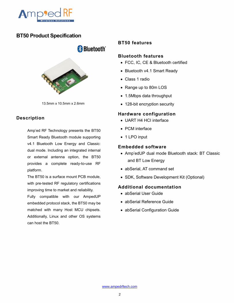
BT50 Product Specification
13.5mm x 10.5mm x 2.6mm
Description
Amp’ed RF Technology presents the BT50
Smart Ready Bluetooth module supporting
v4.1 Bluetooth Low Energy and Classic:
dual mode. Including an integrated internal
or external antenna option, the BT50
provides a complete ready-to-use RF
platform.
The BT50 is a surface mount PCB module,
with pre-tested RF regulatory certifications
improving time to market and reliability.
Fully compatible with our AmpedUP
embedded protocol stack, the BT50 may be
matched with many Host MCU chipsets.
Additionally, Linux and other OS systems
can host the BT50.
BT50 features
Bluetooth features
FCC, IC, CE & Bluetooth certified
Bluetooth v4.1 Smart Ready
Class 1 radio
Range up to 80m LOS
1.5Mbps data throughput
128-bit encryption security
Hardware configuration
UART H4 HCI interface
PCM interface
1 LPO input
Embedded software
Amp’edUP dual mode Bluetooth stack: BT Classic
and BT Low Energy
abSerial, AT command set
SDK, Software Development Kit (Optional)
Additional documentation
abSerial User Guide
abSerial Reference Guide
abSerial Configuration Guide

www.ampedrftech.com
3
Table of Contents
1. Hardware Specifications ........................................................................................................ 4
1.1. Recommended Operating Conditions ...................................................................................................................... 4 1.2. Absolute Maximum Ratings ..................................................................................................................................... 4 1.3. Current Consumption ............................................................................................................................................... 4 1.4. Selected RF Characteristics .................................................................................................................................... 4 1.5. I/O Operating Characteristics................................................................................................................................... 5 1.6. Pin Assignment ........................................................................................................................................................ 6 1.7. Pin Placement Diagram (Top View) ......................................................................................................................... 7 1.8. Layout Drawing ........................................................................................................................................................ 8 2. Module Block Diagram ........................................................................................................... 9
3. Layout Design ......................................................................................................................... 9
3.1. Module Reflow Installation ....................................................................................................................................... 9 3.2. GPIO Interface ....................................................................................................................................................... 10 3.3. PCB Layout Guidelines .......................................................................................................................................... 10 3.4. External LPO Input Circuit ..................................................................................................................................... 11 4. Regulatory Compliance ........................................................................................................ 12
4.1. Modular Approval, FCC and IC .............................................................................................................................. 13 4.2. FCC Label Instructions .......................................................................................................................................... 13 4.3. CE Label Instructions ............................................................................................................................................. 13 5. Ordering Information ............................................................................................................ 13
6. Revision History .................................................................................................................... 13
www.ampedrftech.com
4
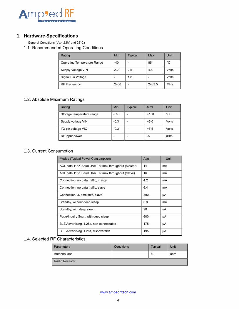
1. Hardware Specifications
General Conditions (VIN= 2.5V and 25°C)
1.1. Recommended Operating Conditions
Rating Min Typical Max Unit
Operating Temperature Range -40 - 85 °C
Supply Voltage VIN 2.2 2.5 4.8 Volts
Signal Pin Voltage - 1.8 - Volts
RF Frequency 2400 - 2483.5 MHz
1.2. Absolute Maximum Ratings
Rating Min Typical Max Unit
Storage temperature range -55 - +150 °C
Supply voltage VIN -0.3 - +5.0 Volts
I/O pin voltage VIO -0.3 - +5.5 Volts
RF input power - - -5 dBm
1.3. Current Consumption
Modes (Typical Power Consumption) Avg Unit
ACL data 115K Baud UART at max throughput (Master) 14 mA
ACL data 115K Baud UART at max throughput (Slave) 16 mA
Connection, no data traffic, master 4.2 mA
Connection, no data traffic, slave 6.4 mA
Connection, 375ms sniff, slave 390 µA
Standby, without deep sleep 3.9 mA
Standby, with deep sleep 90 uA
Page/Inquiry Scan, with deep sleep 600 µA
BLE Advertising, 1.28s, non-connectable 175 µA
BLE Advertising, 1.28s, discoverable 195 µA
1.4. Selected RF Characteristics
Parameters Conditions Typical Unit
Antenna load 50 ohm
Radio Receiver
www.ampedrftech.com
5
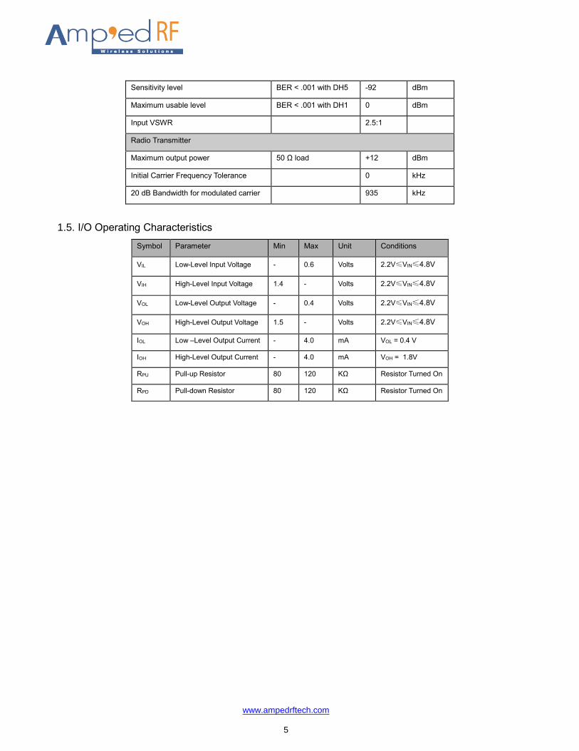
Sensitivity level BER < .001 with DH5 -92 dBm
Maximum usable level BER < .001 with DH1 0 dBm
Input VSWR 2.5:1
Radio Transmitter
Maximum output power 50 Ω load +12 dBm
Initial Carrier Frequency Tolerance 0 kHz
20 dB Bandwidth for modulated carrier 935 kHz
1.5. I/O Operating Characteristics
Symbol Parameter Min Max Unit Conditions
VIL Low-Level Input Voltage - 0.6 Volts 2.2V≤VIN≤4.8V
VIH High-Level Input Voltage 1.4 - Volts 2.2V≤VIN≤4.8V
VOL Low-Level Output Voltage - 0.4 Volts 2.2V≤VIN≤4.8V
VOH High-Level Output Voltage 1.5 - Volts 2.2V≤VIN≤4.8V
IOL Low –Level Output Current - 4.0 mA VOL = 0.4 V
IOH High-Level Output Current - 4.0 mA VOH = 1.8V
RPU Pull-up Resistor 80 120 KΩ Resistor Turned On
RPD Pull-down Resistor 80 120 KΩ Resistor Turned On
www.ampedrftech.com
6
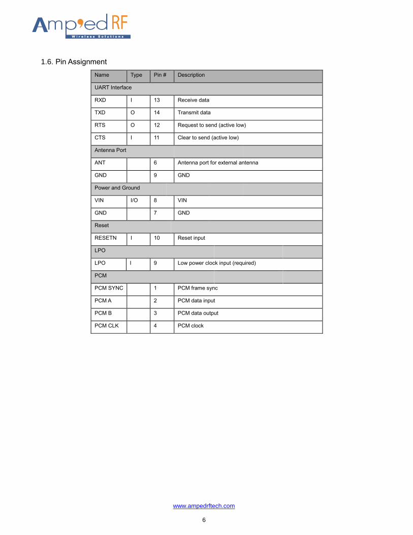
1.6. Pin Assignment
Name Type Pin # Description
UART Interface
RXD I 13 Receive data
TXD O 14 Transmit data
RTS O 12 Request to send (active low)
CTS I 11 Clear to send (active low)
Antenna Port
ANT 6 Antenna port for external antenna
GND 9 GND
Power and Ground
VIN I/O 8 VIN
GND 7 GND
Reset
RESETN I 10 Reset input
LPO
LPO I 9 Low power clock input (required)
PCM
PCM SYNC 1 PCM frame sync
PCM A 2 PCM data input
PCM B 3 PCM data output
PCM CLK 4 PCM clock
www.ampedrftech.com
8
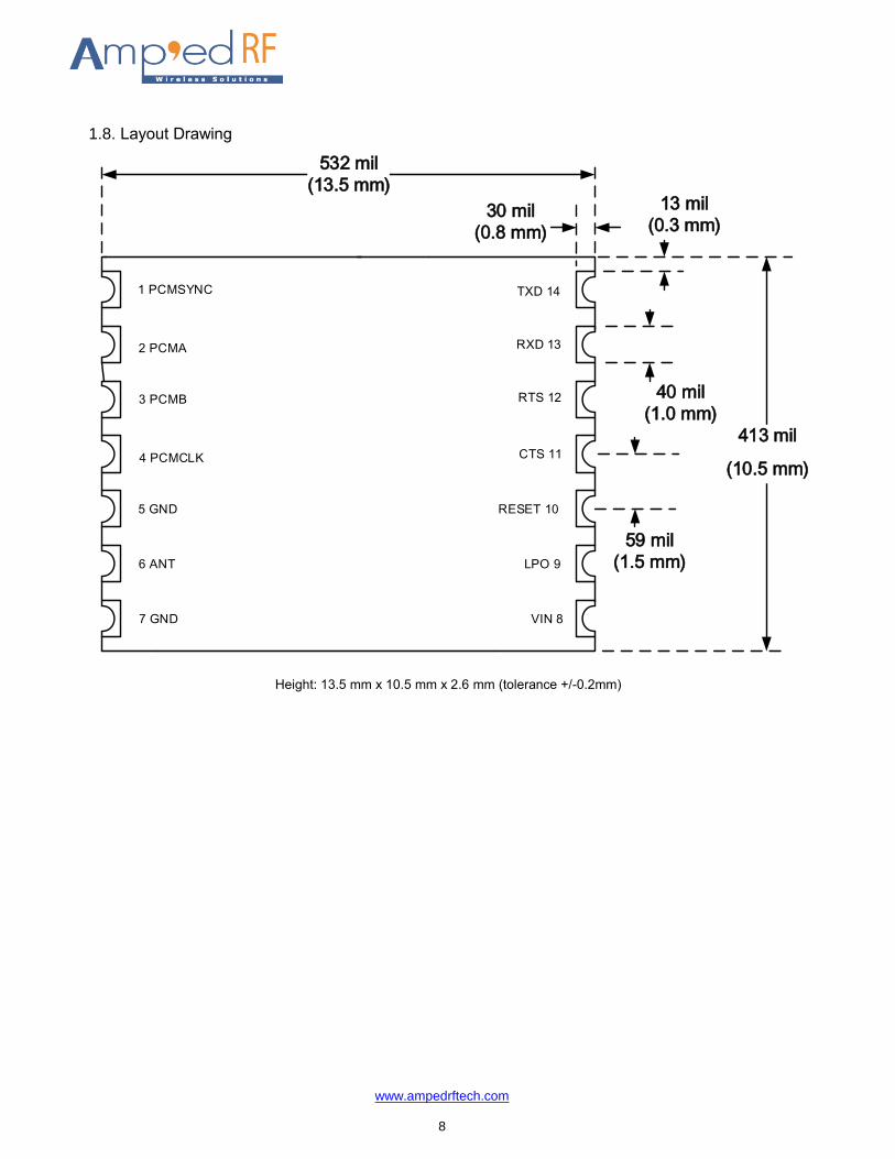
1.8. Layout Drawing
413 mil
(10.5 mm)
1 PCMSYNC
5 GND
2 PCMA
3 PCMB
4 PCMCLK
6 ANT
7 GND
TXD 14
RXD 13
RTS 12
CTS 11
RESET 10
LPO 9
VIN 8
13 mil
(0.3 mm)
40 mil
(1.0 mm)
59 mil
(1.5 mm)
30 mil
(0.8 mm)
532 mil
(13.5 mm)
Height: 13.5 mm x 10.5 mm x 2.6 mm (tolerance +/-0.2mm)
www.ampedrftech.com
9
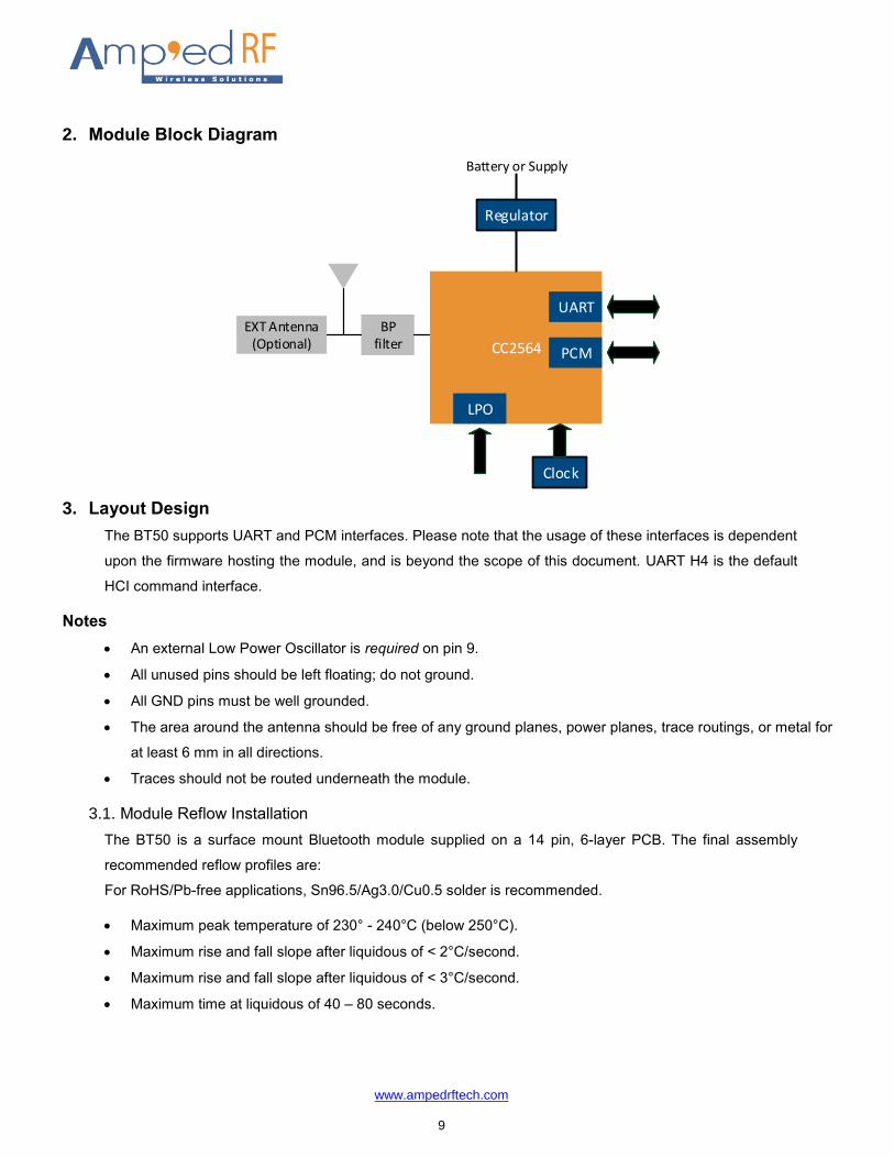
2. Module Block Diagram
BP filter CC2564
EXT Antenna(Optional)
Regulator
PCM
UART
LPO
Clock
Battery or Supply
3. Layout Design
The BT50 supports UART and PCM interfaces. Please note that the usage of these interfaces is dependent
upon the firmware hosting the module, and is beyond the scope of this document. UART H4 is the default
HCI command interface.
Notes
An external Low Power Oscillator is required on pin 9.
All unused pins should be left floating; do not ground.
All GND pins must be well grounded.
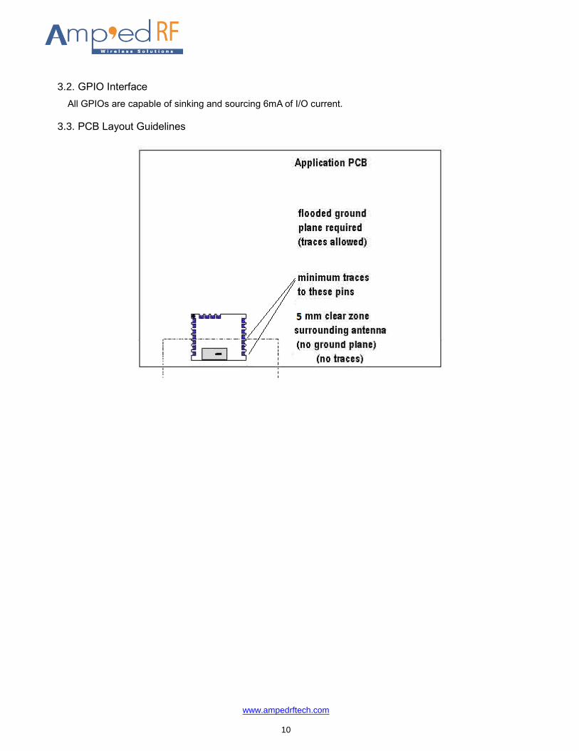
The area around the antenna should be free of any ground planes, power planes, trace routings, or metal for
at least 6 mm in all directions.
Traces should not be routed underneath the module.
3.1. Module Reflow Installation
The BT50 is a surface mount Bluetooth module supplied on a 14 pin, 6-layer PCB. The final assembly
recommended reflow profiles are:
For RoHS/Pb-free applications, Sn96.5/Ag3.0/Cu0.5 solder is recommended.
Maximum peak temperature of 230° - 240°C (below 250°C).
Maximum rise and fall slope after liquidous of < 2°C/second.
Maximum rise and fall slope after liquidous of < 3°C/second.
Maximum time at liquidous of 40 – 80 seconds.
www.ampedrftech.com
10
3.2. GPIO Interface
All GPIOs are capable of sinking and sourcing 6mA of I/O current.
3.3. PCB Layout Guidelines
www.ampedrftech.com
11
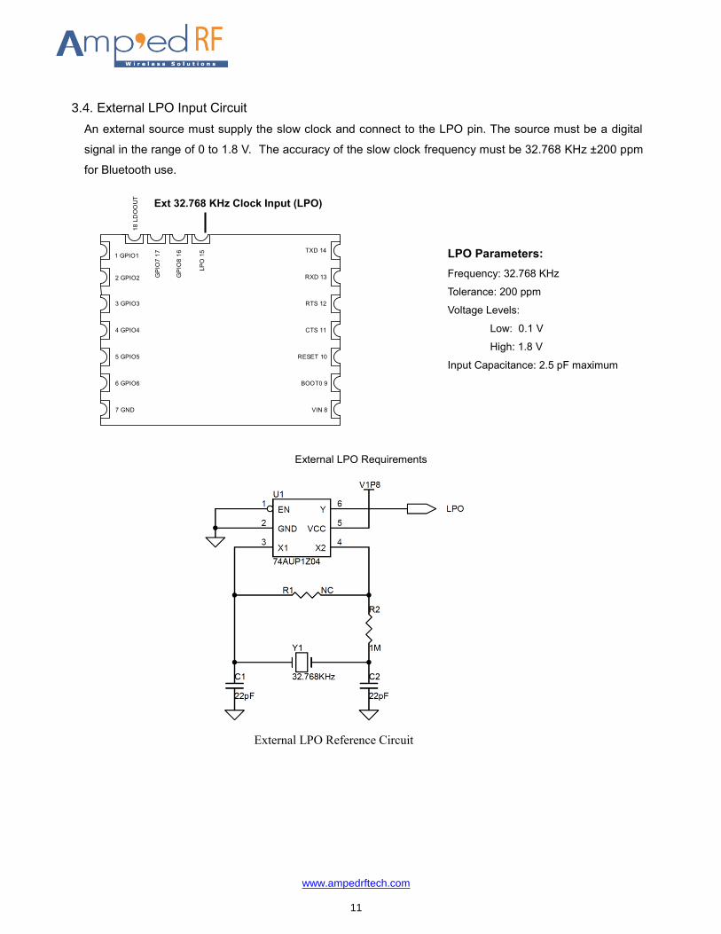
3.4. External LPO Input Circuit
An external source must supply the slow clock and connect to the LPO pin. The source must be a digital
signal in the range of 0 to 1.8 V. The accuracy of the slow clock frequency must be 32.768 KHz ±200 ppm
for Bluetooth use.
1 GPIO1
2 GPIO2
3 GPIO3
4 GPIO4
5 GPIO5
6 GPIO6
7 GND
TXD 14
RXD 13
RTS 12
CTS 11
RESET 10
BOOT0 9
VIN 8
18
LD
OO
UT
GP
IO7 1
7
GP
IO8 1
6
LP
O 1
5
External LPO Requirements
External LPO Reference Circuit
LPO Parameters:
Frequency: 32.768 KHz
Tolerance: 200 ppm
Voltage Levels:
Low: 0.1 V
High: 1.8 V
Input Capacitance: 2.5 pF maximum
Ext 32.768 KHz Clock Input (LPO)
www.ampedrftech.com
12
4. Regulatory Compliance
Federal Communications Commission statement:
This module has been tested and found to comply with the FCC Part15.
These limits are designed to provide reasonable protection against harmful interference in approved
installations. This equipment generates, uses, and can radiate radio frequency energy and, if not installed
and used in accordance the instructions, may cause harmful interference to radio communications. However,
there is no guarantee that interference will not occur in a particular installation.
This device complies with part 15 of the FCC Rules. Operation is subject to the following two conditions: (1)
This device may not cause harmful interference, and (2) this device must accept any interference received,
including interference that may cause undesired operation.
Modifications or changes to this equipment not expressly approved by Amp’ed RF Technology may void the
user’s authority to operate this equipment.
The modular transmitter must be equipped with either a permanently affixed label or must be capable of
electronically displaying its FCC identification number
(A) If using a permanently affixed label, the modular transmitter must be labeled with its own FCC
identification number, and, if the FCC identification number is not visible when the module is installed inside
another device, then the outside of the device into which the module is installed must also display a label
referring to the enclosed module. This exterior label can use wording such as the following: “Contains
Transmitter Module FCC ID: TBD” or “Contains FCC ID: TBD.”
(B) If the modular transmitter uses an electronic display of the FCC identification number, the information
must be readily accessible and visible on the modular transmitter or on the device in which it is installed. If
the module is installed inside another device, then the outside of the device into which the module is installed
must display a label referring to the enclosed module. This exterior label can use wording such as the
following: “Contains FCC certified transmitter module(s).”
To satisfy FCC RF Exposure requirements for mobile and base station transmission devices, a separation
distance of 20 cm or more should be maintained between the antenna of this device and persons during
operation. To ensure compliance, operation at closer than this distance is not recommended. The antenna(s)
used for this transmitter must not be co-located or operating in conjunction with any other antenna or
transmitter.
Industry Canada statement:
Label of the end product:
The final end product must be labeled in a visible area with the following "Contains transmitter module IC:
TBD"
www.ampedrftech.com
13
This Class B digital apparatus complies with Canadian ICES-003.
Cetappareilnumérique de la classe B estconforme à la norme NMB-003 du Canada.
This device complies with RSS-210 of the Industry Canada Rules. Operation is subject to the following two
conditions: (1) This device may not cause harmful interference, and (2) this device must accept any
interference received, including interference that may cause undesired operation.
Ce dispositif est conforme à la norme CNR-210 d'Industrie Canada applicable aux appareils radio exempts
de licence. Son fonctionnement est sujet aux deux conditions suivantes: (1) le dispositif ne doit pas produire
de brouillage préjudiciable, et (2) ce dispositif doit accepter tout brouillage reçu, y compris un brouillage
susceptible de provoquer un fonctionnement indésirable.
4.1. Modular Approval, FCC and IC
TBD
In accordance with FCC Part 15, the BT50 is listed above as a Limited Modular Transmitter device.
4.2. FCC Label Instructions
The outside of final products that contain a BT50 device must display a label referring to the enclosed module.
This exterior label can use wording such as the following:
Contains Transmitter Module
TBD
Any similar wording that expresses the same meaning may be used.
4.3. CE Label Instructions
TBD
5. Ordering Information
Part Name Description
BT50 Internal antenna
BT50-EXT External antenna
6. Revision History
Date Revision Description
29, October 2015 1.0 First release
4, December 2015 1.1 Updated picture