brushless motors: how do they work? - peninsula … · brushless motors: how do they work?...
TRANSCRIPT
Brushless Motors: HOW DO THEY WORK? Brushless DC motors are simple enough: magnets attached to a shaft are pushed and pulled by electromagnetic fields that are managed by an electronic speed control. This differs from brushed (DC) motors which use mechanical brushes rubbing on commutators to time and energize the magnetic fields. It is also different from alternating current (AC) motors which generally use the cycle of the power itself to time the powering of the coils. Brushless motors provide significantly higher power to weight ratios and much better efficiency than traditional brushed motors. That’s the view from 40,000 feet and it’s sufficient for most modelers. However, a deeper understanding of their operation can go a long way to helping a user select the right power system for his application. Each discovery on this road will inevitably lead to more questions, but we have to start somewhere. Let’s begin with the basics of brushless motor operation. Inrunners & Outrunners The most common brushless motors for RC airplane and heli use are known as outrunners as they have permanent magnets arranged around the inside of a can that is then attached to the shaft. The electrical coils are located in the center of the motor with the can and its magnets running on the outside, hence the name outrunner. The functional opposite would be the inrunner type, which is by far the most popular in RC car applications. Inrunners have their magnets attached directly to the motor shaft and the motor coils surround the shaft and magnets. While they look quite different, the operational principles are the same for both types of motor.
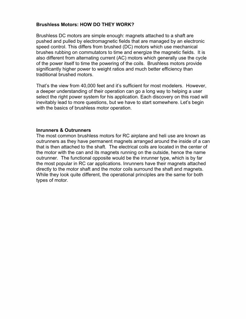
This Neumotors ORK uses a larger-than-normal rotor diameter and a high pole count to generate more torque at the shaft than a traditional inrunner motor. Motors with higher torque can often drive props without using a gearbox. Take a Look Inside Take a brushless motor apart; you’ll see a number of loops of shiny copper wire running parallel to the motor shaft. There will likely be many more than three, but it will be a number divisible by three as each of these coils is actually part of one of three winding circuits in the motor. The coils are distributed such that every third coil is attached to the same motor wire. The steel structure around which the coils are wound is the stator stack, which serves to focus the magnetic field generated by the coils.
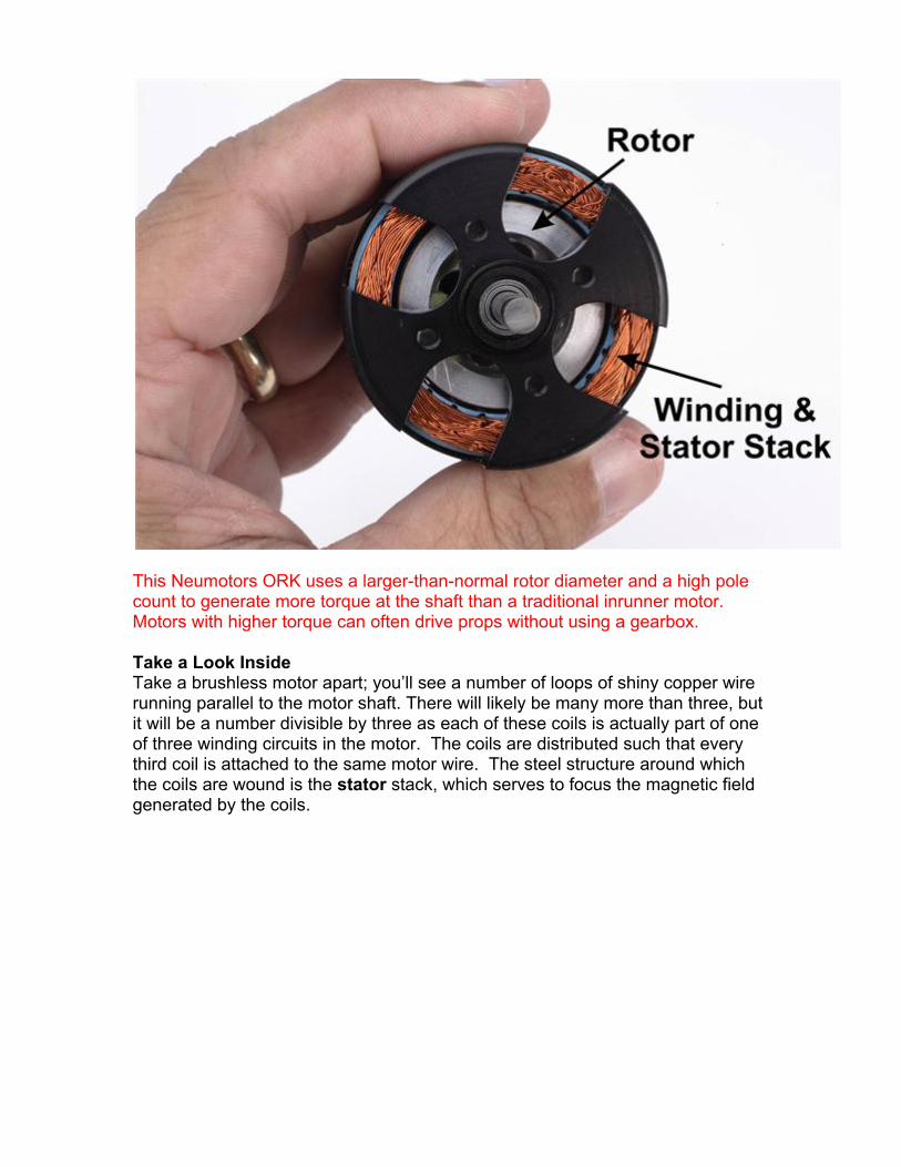
Caption: A stator stack is made of hundreds of rings of special steel which focus the magnetic fields generated by the copper wire that is wrapped around the “teeth” in the stator. More layers of thinner steel generally leads to a more efficient motor -- less heat for a given power output.
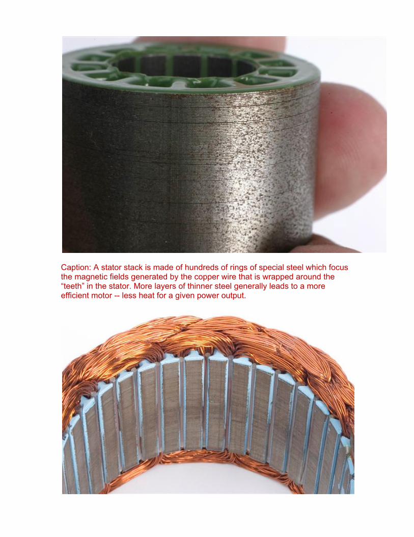
Caption: The motor leads are connected to bundles of wire inside the motor. Those bundles are wrapped around the “teeth” in the steel stator. Note how the bundles are inserted every third space.
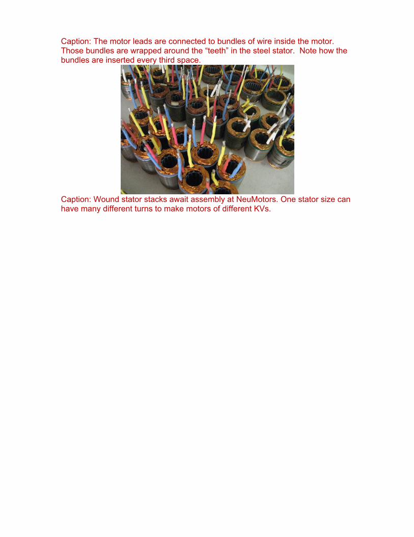
Caption: Wound stator stacks await assembly at NeuMotors. One stator size can have many different turns to make motors of different KVs.
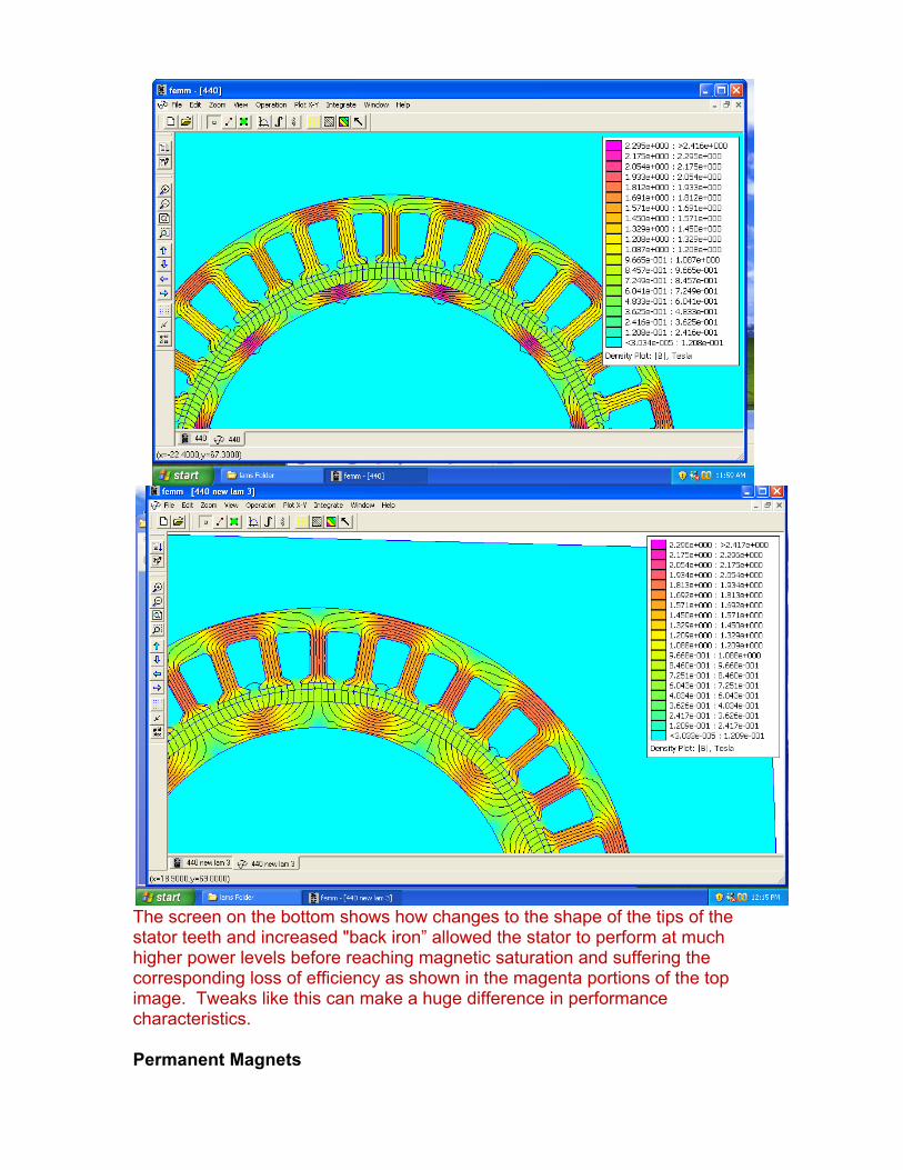
The screen on the bottom shows how changes to the shape of the tips of the stator teeth and increased "back iron” allowed the stator to perform at much higher power levels before reaching magnetic saturation and suffering the corresponding loss of efficiency as shown in the magenta portions of the top image. Tweaks like this can make a huge difference in performance characteristics. Permanent Magnets
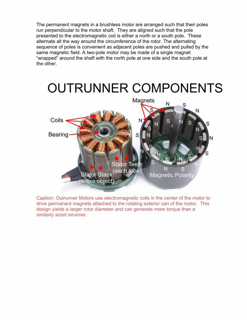
The permanent magnets in a brushless motor are arranged such that their poles run perpendicular to the motor shaft. They are aligned such that the pole presented to the electromagnetic coil is either a north or a south pole. These alternate all the way around the circumference of the rotor. The alternating sequence of poles is convenient as adjacent poles are pushed and pulled by the same magnetic field. A two-pole motor may be made of a single magnet “wrapped” around the shaft with the north pole at one side and the south pole at the other.
Caption: Outrunner Motors use electromagnetic coils in the center of the motor to drive permanent magnets attached to the rotating exterior can of the motor. This design yields a larger rotor diameter and can generate more torque than a similarly sized inrunner.
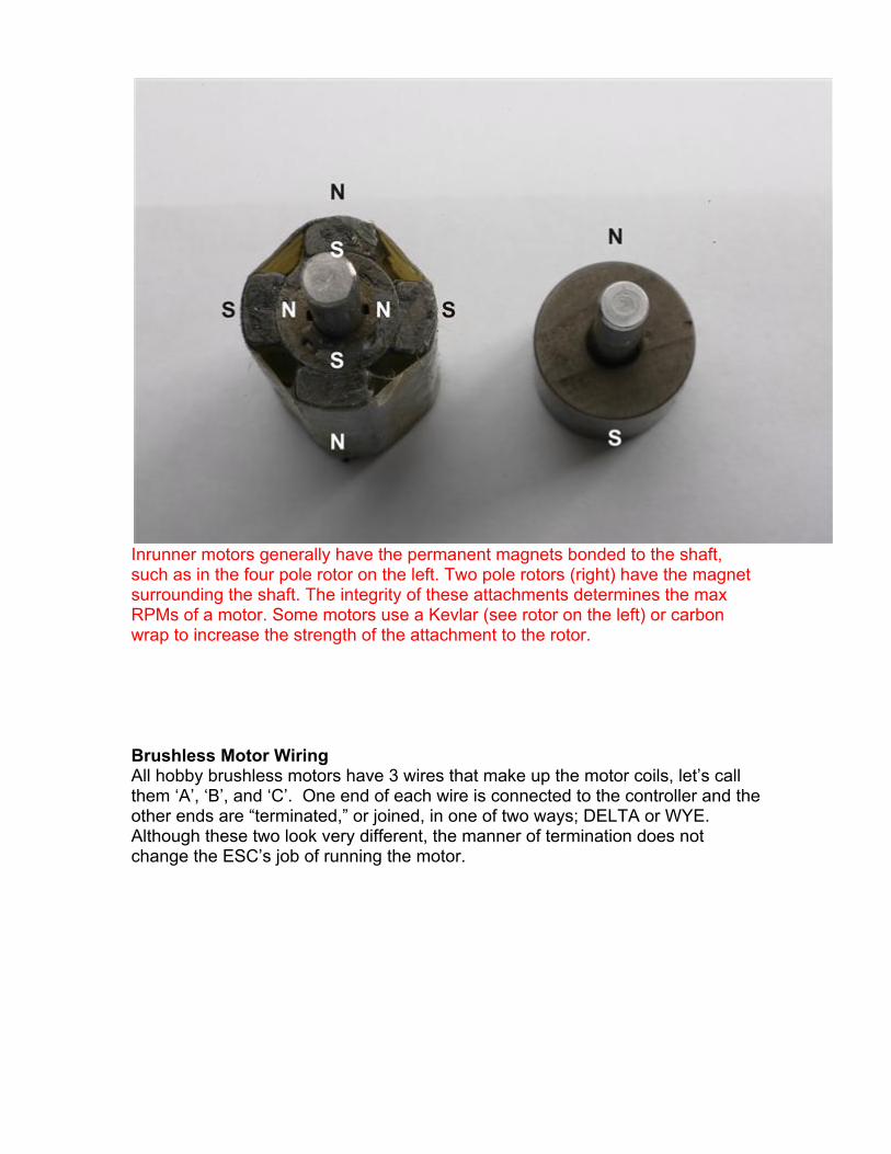
Inrunner motors generally have the permanent magnets bonded to the shaft, such as in the four pole rotor on the left. Two pole rotors (right) have the magnet surrounding the shaft. The integrity of these attachments determines the max RPMs of a motor. Some motors use a Kevlar (see rotor on the left) or carbon wrap to increase the strength of the attachment to the rotor. Brushless Motor Wiring All hobby brushless motors have 3 wires that make up the motor coils, let’s call them ‘A’, ‘B’, and ‘C’. One end of each wire is connected to the controller and the other ends are “terminated,” or joined, in one of two ways; DELTA or WYE. Although these two look very different, the manner of termination does not change the ESC’s job of running the motor.
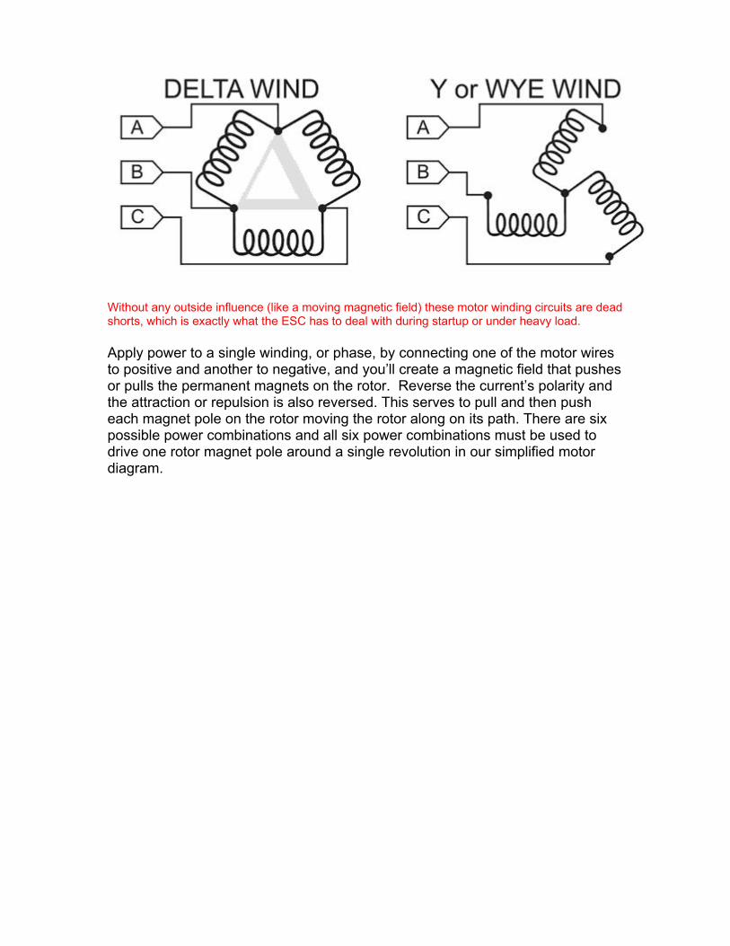
Without any outside influence (like a moving magnetic field) these motor winding circuits are dead shorts, which is exactly what the ESC has to deal with during startup or under heavy load. Apply power to a single winding, or phase, by connecting one of the motor wires to positive and another to negative, and you’ll create a magnetic field that pushes or pulls the permanent magnets on the rotor. Reverse the current’s polarity and the attraction or repulsion is also reversed. This serves to pull and then push each magnet pole on the rotor moving the rotor along on its path. There are six possible power combinations and all six power combinations must be used to drive one rotor magnet pole around a single revolution in our simplified motor diagram.
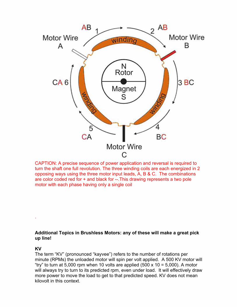
CAPTION: A precise sequence of power application and reversal is required to turn the shaft one full revolution. The three winding coils are each energized in 2 opposing ways using the three motor input leads, A, B & C. The combinations are color coded red for + and black for --.This drawing represents a two pole motor with each phase having only a single coil
. Additional Topics in Brushless Motors: any of these will make a great pick up line! KV The term “KV” (pronounced “kayvee”) refers to the number of rotations per minute (RPMs) the unloaded motor will spin per volt applied. A 500 KV motor will “try” to turn at 5,000 rpm when 10 volts are applied (500 x 10 = 5,000). A motor will always try to turn to its predicted rpm, even under load. It will effectively draw more power to move the load to get to that predicted speed. KV does not mean kilovolt in this context.
Resistance Resistance is a critical concept in understanding the operation of a motor. There are several types of resistance that come into play in an electric motor. Copper loss: All conductors have some level of resistance to electric currents. This resistance causes a portion of the electrical energy passing through the wire to be wasted as unwanted heat instead of creating the desired magnetic field. This type of resistance is known as copper loss. A conductor’s copper loss goes up with the square of the current. A conductor carrying 10 amps has 1/4th the copper loss of that same conductor when it carries 20 amps. Wattage Lost(Watts) = Current (Amps)*Current (Amps)*Resistance(Ohms), although resistance is very small 20*20=400 and 40*40=1600. So doubling the current in a motor results in 4 times the heat. Iron loss To understand Iron loss it helps to understand the relationship between current and magnetic fields. When current flows through a wire it generates a magnetic field, this is a good thing and it is what causes these motors to turn. The inverse of this is also true; when a wire is close to a moving magnetic field a current is generated in the wire (kind of like the alternator in your car). Iron loss happens when the magnets moving near the stator generate electric currents. These electric currents in the steel stators cause heat for the same reason as above with the copper losses, except steel has a much higher resistance than copper. In order to reduce this effect, many ‘thin’ stator laminations are used instead of one solid chunk. Each stator is electrically insulated from the next, reducing the induced currents. Turns: Motors are commonly identified by the number of turns making up the wraps of each coil. Varying the number of wraps of wire in the coils varies the magnetic field. More wraps can yield stronger magnetic fields but thinner wire must be used to fit more wraps in the same space as a larger wire making fewer wraps. There’s always a tradeoff. Thinner wire cannot handle as high a current as thicker wires. Motors made with more turns generally have lower kvs and higher copper losses because of the higher resistance of the winding wire than motors with lower turns and larger winding wires. Permanent Magnets: Permanent magnets used in brushless motors have varying degrees of magnetic strength and temperature resistance. These are related to their composition and manufacture. Permanent magnets generally lose magnetic strength as they are heated and there is a temperature beyond which the magnet suffers permanent loss of magnetism. Demagnetized motors will allow the motor to draw significantly more current and generate more heat while producing progressively less power.
Popular magnetic materials for hobby brushless motors include: Neodymium – excellent magnetic strength, heat tolerant to about 150 degrees C depending on grade (don’t forget that the outside of the can will be a LOT cooler than the magnets, a good rule of thumb, if the outside of the motor is above 100C it is too hot). Samarium Cobalt – not as strong magnetically as Neodymium, but much more heat tolerant. Magnetic qualities can be selected by the manufacturer, and there is often a need to strike a compromise between affordability and performance. Hobbyists are generally reliant on, and trusting of, the manufacturer to disclose the material used. It is often difficult for a hobbyist to verify manufacturer’s claims, so be wary of fantastic claims in this area. Slotted / Slottless Motors A motor with the windings wrapped around “teeth” in the stator is known as a slotted motor. Windings may also be wrapped completely over the stator ring. Motors built in this manner are known as slotless motors. An easy way to tell them apart is to turn the motor shaft. A slotted motor’s rotor poles are magnetically attracted to the “teeth” on the stator plates. You’ll feel a detent, slip, detent in the shaft as it turns, this is known as cogging. A slotless motor doesn’t have teeth, so there’s nothing for the magnets to pull on, thus no cogging. Efficiency A motor’s performance is usually measured in terms of its efficiency. An efficiency change of just a few percentage points can make a huge difference in the amount of power a motor can handle. Example: a motor that is 80% efficient running at 100 watts produces 80 watts of work and 20 watts of heat. (That’s heat equivalent to most hobby soldering irons!) An otherwise identical motor that is 90% efficient produces half the heat, or only 10 watts. If heat dissipation is the only factor limiting the power in the motor, and 20 watts of heat is the maximum amount of heat that the motor can dissipate due to its surface area and cooling air, the 90% efficient motor can handle 200 watts of power before it generates the same 20 watts of heat. Conclusion The design and material quality of motor components have a direct effect on the performance of the motor. Design factors include:
the amount of copper squeezed into the motor, the air gap, or distance between the magnets of the rotor and the windings the material, thickness and shape of the steel used in the stator
laminations the material and strength of the permanent magnets bearings are important too, as well as rotor balance
Just about anybody can make a motor, however, careful attention to engineering principles can make the difference between and efficient and reliable motor and one that performs poorly.