brunel corporation product catalog · 1 brunel torque limiting clutches general information •...
TRANSCRIPT

For catalogs and/or technical assistance:
1304 Twin Oaks StreetWichita Falls, Texas 76302
Phone: (940) 723-7800Fax: (940) 723-7888
E-mail: [email protected]: brunelcorp.com
Product Catalog
Bru
nel C
orp
oratio
n Pro
du
ct Catalo
g2010 World Leader in Modular Torque Limiters

Contentspage
Torque Limiting Clutches
General Information 1
Where to Install / Selection 2
Safety Element Torque Limiters 3
Features and Benefits / How to Select and Order 4
Safety Element Modules 5
Extruder Applications 8
Gear Coupling Applications 11
Water and Waste Water Applications 12
Mining Applications - Contact Brunel: 940.723.7800
Other Applications 16
Torque Limiting Clutches 23
How to Select and Order 24
Type JAB Basic Manual Reset Clutch 25
Type JAB Mounting Variations: JAF, JAS, JAP 26
Type JFV Manual Reset Clutch 29
Type JCB Automatic Reset Clutch 30
Type JBB Basic Automatic Reset Clutch 33
Power Modules
PTM-3 35
Wiring Diagram 36
Specifications 37
PTM-4 38
Wiring Diagram 38
Specifications 39
Mounting Bracket 40
Current Transformer 40
Proximity Sensors
Inductive Sensors 41
Engineering Information
Torque Limiter Selection Checklist 45
Driven Equipment Service Factor 47
Application Formulas 51
Metric Conversion Chart 52
Warranty 53

1
Brunel Torque Limiting Clutches
General Information
• Years Of Trouble Free Service
• Remove Overload Problems
• ±5% Repeatability
• Virtually No Maintenance
• Competitive First Cost
• All Metal, Totally Enclosed
Gone are the problems associated with slow reaction electrical overloads and shear pins which give a wide torque variation and rapidly overheating slip clutches.
Brunel Torque Limiting Clutches will save you money. The initial cost of a Torque Limiter is normally covered by the savings of down time and lost production during the first overload.
Features & Benefits
Torque setting accurate within ±5% is maintained indefinitely
Ease of maintenance is assured by eliminating the need for continuous adjustment
Bi-directional torque transmission is standard
Selection of proper clutch is simplified
Standard unit can be installed on dual direction drive system
Reduced overall length
Reduce the space required and the cost of your drive system
Multiple springs control torque release setting
Increased dependability of drive
Larger range of torque setting is available to meet your specific application
All metal totally enclosed construction
Longer life in contaminated environment
Operator safety improved with enclosed springs
Drive torque is transmitted through tapered jaws on all standard type JA models
Positive drive-no slip, minimal backlash
Timing of drive system is assured
A single Brunel type JA clutch will also function as:
(1) “Dog Clutch”
(2) Overload Release Clutch
Eliminate the need for two separate clutches
Reduce system cost, complexity and size
Automatic and complete disengagement on overload is standard on the JA and JFV4 models
No torque is transmitted, thus preventing damage and machine downtime due to overload
Easy to reset
Because no spring compression or ball alignment is required Type JC and JB are standard with automatic reset
Operator can reset his own machine, avoiding production delays
Typical Applications
Automatic Door Openers
Automatic Furnaces Or Ovens
Bakery Equipment
Bottling Equipment
Conveyors
Drying Drums
Extruders
Film Packaging Machines
Food Processing Equipment
Machine Tools
Mining Equipment
Mixers
PTO Drives
Packaging and Labelling Machinery
Paper Machinery
Printing Presses
Pump Drives
Rolling Mills
Rubber Processing Machines
Textile Machinery
Tractor PTO Driven Winches
Transfer Machines
Special Machinery
Washing Machines
Waste Water Pumps
Woodworking Machinery

2
Alternative positions
Preferred position
Conveyor head shaft
Motor
Gear box
Chain drive
Brunel Torque Limiting Clutches
Where to Install / Torque Limiter Selection
Torque Limiter Selection
Types JA, JB, & JC For release torques up to 48,000 lb in
Decide on manual or automatic reset. Choose a position as near as possible to the expected overload (see diagram).
Calculate the torque setting required at that position. This can be determined from the motor power, r.p.m. and gearing ratio to the driven load or from the maximum permissible torque for drive components such as compressive stress on keys. It is the weakest component that requires protection. Make allowance for motor starting torques (generally twice normal running torque).
Having calculated an approximate setting for the release torque, final adjustments can be made on site.
Check from tables that shaft, sprocket or pulley, etc. can be accommodated.
Selection Example
Model Type JAF7-0500
This specifies:
Manual reset clutch capable of 1000 lb ft torque complete with flexible coupling for shaft-to-shaft application.
To enable us to deal efficiently with your inquiry, we ask you to supply the following facts:-
• Type of application and environment conditions
• R.P.M. of drive
• Release torque required
• Length and diameters of shafts
• Space available between shaft ends
• Overall space available - length and diameter limitations
• Type and sizes of accessories, i.e. sprocket, pulley, etc.
• Any special requirements such as shifter flange, neoprene seals, etc.
In most drive systems there are several
alternate locations where the Brunel clutch
can be installed (fig. 1). The preferred
position is at the driven shaft. This location
places the overload protection clutch at
a point in the drive system where actual
load torque can be accurately monitored.
Alternate locations in the drive system as
shown in Figure 1 are usually subject to
greater variation in torque loads due to the
reduction ratios within the drive system. The
preferred mounting location will provide
better control of the overload release torque
thus preventing unnecessary release at
torques below safe operating levels due to
system inertia and starting torque peaks.
Reduction Gearing
When Brunel Torque Limiting Clutches are installed on large ratio reduction gear boxes care must be taken since it may not be practical to set a torque limiter mounted on the input shaft low enough to provide the proper torque protection on the output shaft. The large reduction ratio will also decrease the accuracy of the output release torque setting if the clutch is located on the input shaft.
High Inertia Drive Systems
When selecting Torque Limiting Clutches for use in high inertia drive system, the location of the clutch must be between the high inertia load (flywheel, large pulley or gear, etc.) and the driven mechanism. Locating the Brunel overload release clutch in this position will protect the driven mechanism from the large inertia forces.
Optional Features
Single Position Re-engagement
For use where timing of machine is required. Available for Type JA. (Standard on JC and JB models.)
Light Duty Springs
For systems requiring very low torque levels and greater range of adjustment sensitivity.
Single Direction Overload ReleaseFor applications where heavy braking is applied. Type JA only.
Dual Level Torque SettingFor heavy overrunning applications which require normal release torque setting in one direction and a lower torque release setting in the opposite direction. Type JA only.
Figure 1

3
Brunel Safety Element Torque Limiters
Torque Limiting Modules
Brunel Torque Limiting Modules have been
specifically designed to provide overload
protection for applications where very high
torques are transmitted and to extend the
range covered by Brunel Type JA units.
The modular system provides facilities for
virtually unlimited torque capacity and lends
itself to many transmission applications
– chain, belt and gear drives, or shaft-to-shaft
gear or flexible coupling drives.
The maximum release torque depends on the
number and size of Torque Limiting Modules
that can be incorporated, and the size of
the unit that can be accommodated within
the confines of the installation. Internally
& externally adjusted modules provide
repeatability better than ±5%, however
externally adjusted modules are preferred
when the application is required to operate
within minimal variations between static &
dynamic disengagement.
Y
X
YX
C
Fu
J B A
F
K
ED
G
H
H1
Disengaged
plunger, and once this condition is reached the flanges are completely free to rotate independently. A suitable switch can be incorporated in the assembly to switch off the drive motor or operate a warning device when the Torque Limiting assembly disengages. Resetting is a simple matter of first re-aligning the flanges X and Y and then tapping each module plunger back with a soft mallet to allow the circle of balls to return to their original position and the large steel ball to return to its location in the detent pocket.
Construction
The Brunel Torque Limiting Module is constructed from the finest quality materials. Many of the vital components are made from high quality tool steels, through hardened to Rockwell C62, and precision ground to close tolerances.
Normal Operation
The flanges X and Y are driven by a large steel ball 2, located in the detent pocket 1, which is retained by a plunger 3. This in turn is retained axially by means of a system of angled races 6,8 biased by pressure from the Belleville springs 5, acting on a circle of balls 7.
Disengagement
On overload, relative angular movement between flanges X and Y imparts a tangential force (Fu) on the large steel ball, forcing it clear of the detent pocket back against the plunger. This in turn causes the plunger to be forced through the circle of balls overcoming the spring loading on the angle races. In this position, the balls are resting on the large diameter of the
Detent Pockets
Internally & externally adjusted modules can have through hole or blind hole detents (see diagrams left and on page 5). The type of detent is dependent upon the design constraints.
All modules are required to be preloaded. In the case of the through hole module this is done by tightening the set screw at the base of the detent pocket. In the case of the blind hole module this is done by the means of shims under the module.
Selection
To apply the modules in the form of a torque limiter, it is necessary to determine the quantity of modules needed for the required torque capacity at a specific radius from the axis of rotation.
No. of Modules = MTorque (lb in) = TTangential Force = FuMounting Radius of Modules = RAD
M = T Fu x RAD
T = M x Fu x RAD

4
Brunel Safety Element Torque Limiters
The Brunel Safety Element Torque Limiters
have been specifically designed to offer
overload protection on applications where
very high torques are transmitted, and so
extend the range covered by the standard
Brunel units.
Gone are the problems associated with slow
reaction electrical overloads, shear pins which
give a wide torque variation, and rapidly
overheating slip clutches.
Features and Benefits
Complete disengagement on overload No torque transmission after overload release
All metal, totally enclosedLong life in harsh environments; completely enclosed torque transmitting components
Easy to resetReduces downtime, lost production, saves time and money; the safety elements can be reset in minutes; eliminate searching for misplaced shear pins; can be reset by the operator
Tamperproof torque adjustmentVirtually eliminates increasing the capacity of the drive by unauthorized personnel without the use of special tools, shims, springs, spacers, etc.
Quick and complete disengagementEliminates problems associated with slow reaction electrical overload sensing devices, shear pins (which give a wide torque range) and rapidly overheating slip clutches
Positive drive/no slipEliminates damaging heat build–up and maintains equipment timing while engaged
Torque setting accuracy maintained indefinitelyEase of maintenance is assured by eliminating continuous adjustments for wear and fatigue
Features and Benefits / How to Select and Order
How to Select and Order
Because of the custom and highly technical nature of this design, please consult Brunel with full application data. We will guide you in the selection and ordering of these units.
Through hardened, chromium tool steel, torque transmitting componentsVirtually eliminates wear on these critical components
Precision Belleville springsEnsure accurate and repeatable release torque setting
Spring loaded, ball detent torque transmissionEliminates problems with sheared pins fatigueEliminates the problems associated with “substitute” shear pin materials
Modular element design/four basic sizes of elementsEnables a design suited to your torque requirements, at a competitive priceThe accuracy and repeatability can allow for downsized motors, reducers, etc. because there is no need for large service factors; the safety elements can be designed in for protection, and the power transmission equipment sized to do the job properly and efficiently

5
Brunel Safety Element Torque Limiters
Internally Adjusted Modules
Externally Adjusted Modules
Note: Internal design features may vary between sizes
Y
X
YX
C
Fu
J B A
F
K
ED
G
H
H1
Engaged
Brunel Tangential Force Fu Dimensions in mm and inches P/N lb N A B C D E F G H H1 J K
JSE.5-0014 2,250 10,000 56 36 19.5 20 14 44.5 1.8 28.5 31.5 22 17
2.20 1.42 0.77 0.79 0.55 1.75 0.07 1.12 1.24 0.87 0.67
JSE1-0014 4,000 17,800 66 40 24.5 25 16 54.5 1.5 20 24 27 30
2.60 1.57 0.96 0.98 0.63 2.15 .060 0.79 0.94 1.06 1.18
JSE2-0014 11,000 48,900 105 66 35 45 45 72 2.5 4 11 25 35
4.13 2.60 1.38 1.78 1.78 2.83 0.10 0.16 0.43 0.98 1.38
JSE3-0014 38,000 169,000 170 120 70 45 45 130 3 9 23 48 40
6.69 4.72 2.76 1.78 1.78 5.12 0.12 0.35 .901 1.89 1.57
Consult factory for special application
Brunel Tangential Force Fu Dimensions mm and in
P/N lb N A B C D E G H H1 J
JSE.5-0025 2,250 10,00056
2.20550
1.96919.5.768
15.591
14.551
1.5.059
672.638
3.5.138
20.787
JSE1-0025 4,000 17,00066
2.59850
1.96924.5.965
20.787
16.630
2.5.098
773.032
4.158
371.458
JSE2-0015 5,900 26,000105
4.13469
2.71635
1.37835
1.37845
1.7722.5
.098107
4.2138
.31515
.591
JSE3-0015 15,000 67,000105
6.696240
9.44869.5
2.735 N/A45
1.7623
.118138.55.454
34.81.370
411.611
Note: Internal specifications may vary between sizes
D
H1
E H
JG
B AC
8 9
Adjustment
Adjustment of the tangential force Fu, canbe made by adjusting the spring housing (9), so altering the spring force. Ensure that on assembly any clearancebetween the driving ball and detent pocket is eliminated by adjusting the quantity of shims (8) under the clamp face of the module.

6
Externally Adjusted Disconnect Modules
Adjustment
Adjustment of the tangential force (Fu), can be made by removing the security cover 1 from the mounting flange and adjusting the housing 2, so altering the spring force.
This procedure discourages tampering by unauthorized personnel.
C B A
H
ED
GH1
F
12
Brunel Safety Element Torque Limiters
Features and Benefits
Very accurate release torque repeatability with minimal variation between static and dynamic release. Versatile installation allows for the torque limiter center section to be removed without the need to move the motor or gearbox.
Individual modules are preset to provide the required release torque. Any maintenance of the modules is a straightforward operation. A simple removal operation allows for module recalibration without having to replace the complete unit. By holding spare modules in stock already preset to the required release torque keeps downtime to an absolute minimum.
Manual reset of the torque limiter can only be carried out when the drive is at rest. Resetting is achieved by realigning the two halves of the unit and then lightly tapping each module fitted, with a soft mallet.
Lubrication of the unit is via easy access grease nipples. Proximity sensor targets are included to provide the means to switch off the drive after an overload occurs. While each torque limiter assembly is normally factory preset, if required site adjustments can be carried out, a setting chart with instructions is provided for this purpose.
Externally Adjusted Disconnect Modules
Please note a security key is required and adjustment should only be carried out by an authorized person.
• Accurate release torque repeatability
• Simple fast manual re-engagement
• Low-cost maintenance
• The preferred protection for many extruder manufacturers
Brunel Tangential Force Fu Dimensions in mm and inches
P/N lb N A B C D E F G H H1
JSE.5-0018 2,250 10,00056
2.2050
1.9719.50.77
150.59
140.55
200.79
1.50.60
77.53.05
813.19
JSE1-0018 4,000 17,00066
2.6050
1.9725
0.9820
0.7916
0.6337
1.462.5
0.101003.94
1044.09
JSE2-0018 6,100 27,0001064.17
793.11
351.38
351.38
451.77
100.40
2.50.10
1495.87
1566.14
Note: Internal design features may vary between sizes
P/N: JSE1-0025

7
Brunel Torque Limiting Modules have been specifically designed to provide overload protection for applications where very high torque’s are transmitted, and to extend the range covered by Brunel Type JAB units.
The modular system provides facilities for virtually unlimited torque capacity and lends itself to many transmission applications – chain, belt and gear drives, or shaft-to-shaft gear or flexible coupling drives.
The maximum release torque depends on the number and size of Torque Limiting Modules that can be incorporated, and the size of the unit that can be accommodated within the confines of the installation. Internally & Externally adjusted modules provide repeatability better than 5%, however Externally adjusted modules are preferred when the application is required to operate within minimal variations between static & dynamic disengagement.
Construction
The Brunel Torque Limiting Module is constructed from the finest quality materials. Many of the vital components are made from high quality tool steels, through hardened to Rockwell C62, and precision ground to close tolerances.
Normal Operation
The flange connection is driven by a large steel ball (2), located in the detent pocket (1), which is retained by a plunger (3). This in turn is retained axially by means of a system of angled races (5,7) biased by pressure from the Belleville springs (4), acting on a circle of balls (6).
Disengagement
On overload, relative angular movement between the flanges imparts a tangential force (Fu) on the large steel ball, forcing it clear of the detent pocket back against the plunger. This in turn causes the plunger to be forced through the circle of balls overcoming the spring loading on the angle races. In this position, the balls are resting on the large diameter of the plunger, and once this condition is reached the flanges are completely free to rotate independently. A suitable switch can be incorporated in the assembly to switch off the drive motor or operate a warning device when the Torque Limiting assembly disengages.
After first ensuring that the drive is isolated, resetting is a simple matter of first realigning the flanges and then tapping each module plunger back with a soft mallet to allow the circle of balls to return to their original position and the large steel ball to return to its location in the detent pocket.
Detent Pockets
Internally & externally adjusted modules can be through hole or blind hole detent fixing (See diagrams on opposite page). The type of detent fixing is dependant upon the design constraints.
The mechanical clearance in the Module assembly should be eliminated by pre-loading the detent pocket (1) against the driving ball (2).
Selection
To apply the modules in the form of a torque limiter it is necessary to determine the quantity of modules needed for the required torque capacity at a specific radius from the axis of rotation.
No. of modules = Torque (Nm) x 1000 Fu (N) x radius (mm) x K
K = 0.65 for General Applications.
K = 0.5 for Steelwork Applications.
Brunel Safety Element Torque Limiters
Torque Limiting Modules
Fu
degagnesiDdegagnE
1 2
6
3
4
75

8
Brunel Safety Element Torque Limiters
• Modular Design Simplifies MaintenanceUser can replace Safety Elements (the working components) without removing clutch from shaft
Clutch can be removed (dropped out) without moving motor back
• Module Designs Available
Standard Internally Adjustable Modules
Externally Adjustable Modules *(EA)Torque adjustment by micrometer graduations
Tamper proof externally adjustable design
Disconnectable Modules *(D)Disconnect motor for testing of motor function and torque limiter functionTamper proof internally adjustable design
Externally Adjustable / DisconnectableModules *(EAD) Incorporates both features above
• Simple Manual Reset -- without reversing drive
• Precision Ball Detent/Belleville Spring Design
(+0 to -10% repeatability)
• Adaptable to All Drive Configurations
• Eflex Coupling Standard, Other Types Available
• Large Torque & Bore Capacity
• Turning bar holes standard
OETL - Original Extruder Torque Limiter
400HP Twin Screw Extruder Clutch Coupling Between Motor and Reducer
900HP Twin Screw Extruder Clutch Coupling * part number suffix
Externally Adjustable / Disconnectable Module *(EAD)
Features & Benefits
Brunel Safety Element Torque Limiters have been protecting industrial power transmission systems around the world since 1971. The Extruder Safety Element “SE” Series Torque Limiters are designed specifically for the precision requirements of twin screw extruder applications. They are totally enclosed and made exclusively of steel (except coupling flex elements & seals). The wearing parts in the Safety Element Modules are D-2 tool steel thru hardened to Rc 62 minimum. Tapered roller bearings are incorporated in the design for long life, and are regreaseable through a grease fitting and grease relief valve. Modular construction provides design flexibility and simplified maintenance. Safety Elements
are precision Belleville spring loaded, single ball detent design. A unique over-center mechanism insures complete disengagement on overload and simple, fast manual re-engagement.
Safety Element Torque Limiters completely disengage on overload thus preventing damage and down time to the equipment. When applied on motor output shafts of twin screw extruder drive systems, the “SE” Torque Limiter protects the reducer and twin screws from potential damage upon overload.

9
Brunel Safety Element Torque Limiters
For Extruder Applications
Brunel - Extruder Torque Limiter Dimensions (millimeters/inches)
Torque Torque Dimensions in mm and inches Limiter Brunel Range Max. Bore Max. Bore DBSE Size P/N lb in A B C D E F G H I J
1 JSE.5-0104MAEAD 3,540-11,328 206 280.29 194.95 120 75 85.73 110 160.28 110 62.34
8.110 11.035 7.675 4.724 2.953 3.375 4.311 6.310 4.33 2.454
2 JSE1-0128MAEAD 9,650-30,530 304.8 338.65 219.88 130 90 104.77 159 250.8 135 83
12.000 13.33 8.657 5.118 3.543 4.125 6.260 9.874 5.315 3.268
3A JSE1-0129MAEAD 11,284-36,108 360 371.5 240 150 90 136.525 191 300 135 96.8
3B JSE1-0129MBEAD 22,568-59,737 14.173 14.626 9.449 5.906 3.543 5.375 7.50 11.811 5.315 3.811
4A JSE2-0241MAEAD 23,895-76,464 470 451.27 339.94 170 130 171.45 260 400 165 98
4B JSE2-0241MBEAD 47,790-152,928 18.5 17.767 13.383 6.693 5.118 6.75 10.236 15.748 6.496 3.858
Torque Safety Max. Installation Max. Operating Limiter Brunel Element Eflex Gap Misalignment Misalignment Weight Size P/N Size / Qty K L M N O Angular Parallel Angular Parallel lb. mm / in mm / in mm / in mm / in
1 JSE.5-0104MAEAD JSE.5 / 2 5 108 39.5 67.236 3.302 0.3 .05 0.6 0.8 93
0.197 4.252 1.555 2.647 0.130 0.012 0.024 0.024 0.031
2 JSE1-0128MAEAD JSE1 / 2 5 120.65 45 100 5 0.35 0.5 0.7 0.8 167.0
0.197 4.750 1.772 3.937 0.197 0.014 0.020 0.028 0.031
3A JSE1-0129MAEAD JSE1 / 2 5 139.7 68 100 5 0.4 0.5 0.8 0.8 259.3
3B JSE1-0129MBEAD JSE1 / 4 0.197 5.500 2.677 3.937 0.197 0.016 0.20 0.031 0.031 265.3
4A JSE2-0241MAEAD JSE2 / 2 6 203.2 68 135.7 6.35 .5 .5 1 1 633.7
4B JSE2-0241MBEAD JSE2 / 4 0.236 8.000 2.677 5.343 0.250 0.020 0.020 0.039 0.039 649.3
A
C
DE F
G
H
I J L
B
K
M
N OAxial movement
on overload
Proximity Sensor Targets(to Sense Disengagement)
Consult factory for special application

10
CP
K
L
T
SQRMB
ED
Brunel Safety Element Torque Limiters
UEP—Ultimate Extruder Protection Torque Limiters w/Torsional Couplings
Brunel Corporation has — through extensive experience — developed the Ultimate Extruder Protection device affording reliable protection for twin screw extruders. Based on over 30 years experience in arduous applications particularly in the steel industry has led to the development of the UEP Brunel Modular Torque Limiter which has become the industry standard for twin screw extruder machines.
Dimensions mm and in
Rigid Hub Flex Coupling
Q R
Brunel P/N B C D E T S L Min Bore
Max Bore
K M P Min Bore
Max Bore
Weight kgs/lbs
JSE.5-0234A232
9.13462.3
2.453112
4.4093
0.118264
10.394130
5.118106
4.17332
1.25990
3.5433.2
0.126106.44.189
953.740
351.378
702.756
3986
JSE1-0237A278
10.94583.5
3.287134
5.2764
0.157325
12.795165
6.496121
4.76440
1.575115
4.5283.2
0.126128.65.063
1204.724
401.575
853.346
70154
JSE1-0238A317
12.48083.5
3.287133
5.2364
0.157350
13.780165
6.496121
4.76440
1.575115
4.5283.2
0.126152.4
6145
5.70955
2.16595
3.74090
198
JSE1-0238B320
12.59896.7
3.807138
5.4334
0.157363
14.291190
7.480121
4.76450
1.969135
5.3153.2
0.126152.4
6145
5.70955
2.16595
3.740106234
JSE1-0239B378
14.88296.7
3.807138
5.4334
0.157407
16.024234
9.213140
5.51255
2.165165
6.4963.2
0.126179.47.063
1706.693
552.165
1154.528
163359
JSE1-0300C467
18.386110.74.358
1365.354
40.157
44117.362
2349.213
1405.512
552.165
1656.496
4.80.189
2198.622
1907.480
702.756
1405.512
231509
Ratings and Dimensions
Brunel P/NMaximum PresetTorque Nm/lb-in
Minimum PresetTorque Nm/lb-in
MaximumSpeed RPM
CouplingSize
ModuleSize
Quantity ofModules
JSE.5-0234A148013100
1481310
3000 0.2RB JSE.5 2
JSE1-0237A304626960
4934364
2800 0.37RB JSE1 2
JSE1-0238A357731660
5795125
2800 0.73RB JSE1 2
JSE1-0238B668859195
11229931
2500 0.73RB JSE1 4
JSE1-0239B878677764
142012568
2500 1.15RB JSE1 4
JSE1-0300C14280126392
231020446
2200 2.15RB JSE1 6

11
Brunel Safety Element Torque Limiters
For American Gear Coupling
Model Number SE1025 SE1030 SE2035 SE2040 SE2045 SE2050 SE2055
Gear Coupling Sze 2.5 3 3.5 4 4.5 5 5.5
Size of Module JSE1 JSE1 JSE2 JSE2 JSE2 JSE2 JSE2
Quantity of Modules 4 6 3 4 5 6 7
A - Pitch Circle Diameter of Modules 11.81 11.81 15.35 15.35 18.11 18.11 21.26
Minimum Release Torque (lb in) 17,700 26,600 46,050 61,400 90,500 108,700 148,800
Maximum release Torque (lb in) 92,500 138,800 253,300 337,700 498,000 597,600 818,500
Recommended Max. Setting (lb in) 60,100 90,200 164,600 219,500 323,700 388,500 532,000
B - Torque Limiter Outside diameter 14.17 14.17 18.5 18.5 21.25 21.25 24.41
C - Torque Limiter Width 3.60 3.60 3.62 3.62 3.62 3.62 3.62
D - Overall Width 4.96 4.96 7.83 7.83 7.83 7.83 7.83
E - Breakout Extension 0.25 0.25 0.32 0.32 0.32 0.32 0.32
F - Flange Gap 2.07 2.07 3.62 3.62 3.62 3.62 3.62
G - Gear Clpg Bolt Circle Diameter 7.125 8.125 9.5 11 12 13.5 14.5 H - Tapped Hole Size 5/8" 5/8" 3/4" 3/4" 3/4" 7/8" 7/8"
I - Number of Tapped Holes 6 8 8 8 10 8 14
Shipping Weight (lbs) 127.6 132 290 297 365.2 372 405
Model Number SE3060 SE3070 SE3080 SE3090 SE30100 SE30110 SE30120
Gear Coupling Sze 6 7 8 9 10 11 12
Size of Module JSE3 JSE3 JSE3 JSE3 JSE3 JSE3 JSE3
Quantity of Modules 3 3 4 5 6 8 9
A - Pitch Circle Diameter of Modules 22.83 25.98 28.35 31.1 33.07 35.43 38.58
Minimum Release Torque (lb in) 231,200 263,000 382,700 524,800 669,700 956,600 1,171,900
Maximum release Torque (lb in) 1,301,300 1,480,900 2,154,600 2,954,500 3,770,000 5,385,400 6,597,200
Recommended Max. Setting (lb in) 845,900 962,900 1,400,500 1,920,400 2,450,500 3,500,500 4,288,200
B - Torque Limiter Outside diameter 27.95 31.1 33.46 36.22 38.19 40.55 43.7
C - Torque Limiter Width 3.66 5.24 5.63 5.63 5.63 6.02 6.02
D - Overall Width 10.71 10.71 10.71 10.71 10.71 10.71 10.71
E - Breakout Extension 0.55 0.55 0.55 0.55 0.55 0.55 0.55
F - Flange Gap 3.66 3.66 3.66 3.66 3.66 3.66 3.66
G - Gear Clpg Bolt Circle Diameter 15.75 18.25 20.75 23.25 25.25 27.5 30 H - Tapped Hole Size 7/8" 1" 1.25" 1.25" 1.25" 1.5" 1.5"
I - Number of Tapped Holes 14 16 16 18 18 18 18
Shipping Weight (lbs) 737 1045 1287 1540 1738 2112 2464
The “SE” Series are manual reset, modular ball
detent torque limiters. They are mounted
between coupling halves, or U-joint flanges
or other arrangements. The module
construction allows assemblies of unlimited
torque capacity, protecting the largest drive
lines made.
Consult factory for special application
F
A
E
H, I
B
C
D
G

12
Brunel Safety Element Torque Limiters
Features & Advantages
• Modular Ball Detent/Disc Spring Design
• All Major Components 316 Stainless Steel
• Four Safety Element Styles Available
1) Externally Adjustable
2) Disconnectable (Tamperproof)
3) Standard (Tamperproof)
4) Externally Adjustable Disconnectable
• All Wearing Surfaces D-2 Tool Steel through
hardened to Rc62 min.
• Complete Disengagement on Overload
• Simple Manual Reset
• Multiple “O” Ring Seals
• Adapts to All Drive Configurations
• Large Torque & Bore Capacity
Brunel Safety Element Torque Limiters have been protecting industrial power transmission systems around the world since 1971.
The Waste Water Safety Element “SE” Series Torque Limiters are designed specifically for the outdoor, corrosive “waste water” environment. They are made of 316 stainless steel throughout with the exception of D-2 ( Rc 62) tool steel “ working parts” in the safety element, “O” ring seals and PTFE bearings. The internal parts are packed with grease and are externally regreaseable. Eight “O” ring seals prevent contaminants from entering the unit while a grease vent allows added grease to escape. Modular construction provides design flexibility and simple maintainability. Safety elements are precision
For The Fresh Water and Waste Water Treatment Industry
Belleville spring loaded, single ball detent design. A unique over-center mechanism ensures complete and bidirectional disengagement on overload and simple, fast manual re-engagement. Four types of Safety Elements: standard, disconnectable, externally adjustable and externally adjustable disconnectable are available and are interchangeable on the base unit.
Safety Element Torque Limiters completely disengage on overload thus preventing damage and down time to the equipment. When applied on reducer output shafts in rectangular settling tank drive systems, the “SE” Torque Limiter protects the reducer, drive chain, drag chain and flight bars. They can also be applied on screw conveyor drives or other sludge collection systems that have potential for jamming.

13
Brunel Safety Element Torque Limiters
Engineering Data
Item Description Qty. Item Description Qty. Item Description Qty.
1 Module Carrier Hub 1 9 PTFE Bearing 1 17 1/4" -28 x 5/8" S.H.C.S. 4
2 Detent Pocket Plate 1 10 PTFE Bearing Ring 1 18 Grease Fitting 1
3 Retaining Plate 1 11 PTFE Thrust Pad 1 19 Grease Relief Valve (1/8 NPT) 1
4 JSE1-0015 External Adjust SE 1 12 Blanking Plate 1 20 Detent Pocket 1
5 5/16" -24 x 5/8" S.H.C.S. 8 13 Blanking Plate Seal 1 21 Pointer ( Alignment) 1
6 "O" Ring Seal 1 14 Stainless Steel S.H.C.S. 6 or 8 22 "O" Ring Seal 1
7 "O" Ring Seal 1 15 Stainless Lock Washer 6 or 8
8 5/16" -24 x 1/2" socket set screw 2 16 Stainless Flat Washer 6 or 8
Section X-X
Standard
Safety Element
(Tamperproof)
Disconnectable
Style
(Tamperproof)
Externally
Adjustable
A B
X
X
E
G
J
CK
F
H (Axial Movement on Overload)
M
BR
UN
EL Torq
ue Lim
iterP/N
: JSE1-0201EA, S/N
1288B
RU
NEL C
orp
oratio
nW
ichita Falls, TX
(940) 723-7800
D
L
Disconnectable
Style
Externally
Adjustable
Externally
Adjustable
5 3 22 8 7 11 9 14 15 16 21 2 20 6 5 10
18
4
13 12
19
17
1
Consult factory for special application
Brunel Safety Torque Safety Dimensions in inches Part No. Element Range Element Min H78 Series Qty. lb in Style A B C D E F G H J K L M Sprocket
max.
JSE1-0100 1 750 - 7,540 Standard 6.52 .162 Qty 6 9
2 1,500 - 15,080 Disconnect 6.80 6.10 5.66 1.750 3.62 3.64 3.00 .162 1.58 4.50 1.925 3/8-16 Tooth
External Adj. 7.32 .211
Ext. Adj. Disc. 7.56 .250
JSE1-0200 1 1,080 - 11,000 Standard 6.52 .162 Qty 6 11
2 2,160 - 22, 000 Disconnect 6.80 7.68 7.25 2.9375 3.62 4.724 3.00 .162 1.58 5.75 2.75 1/2-13 Tooth
External Adj. 7.32 .211
Ext. Adj. Disc. 7.56 .250
1 3,400 - 15,000 Standard 8.10 .162 Qty 8 11
JSE1-0400 2 6,800 - 30,000 Disconnect 8.40 9.75 9.25 3.75 5.10 6.00 3.00 .162 1.58 6.60 3.83 3/8-16 Tooth
3 10,200 - 45,000 External Adj. 8.90 .211
4 13,600 - 60,000 Ext. Adj. Disc. 9.04 .250

16
Brunel Safety Element Torque Limiters
Applications
Torque Limiting Module Unit for Helicopter Rotor Test Rig
12 off JSE3 Cam Disconnect Modules on a 470.36mm PCD
Maximum Preset breakout torque = 281,950 lb ft
Minimum Preset breakout torque = 188,109 lb ft
Maximum operating speed = 275rpm
Modules can be disconnected with the cam facility so that a lower number of modules are engaged. The breakout torque will be reduced proportionally.
Torque Limiting Module Unit Fitted to Morbark Wood Grinding Machine
Provided to protect the Diesel Engine, u-joint and the rotary cutter head. Various sizes of unit supplied ranging from 46,900 to 195,000 lb in depending on release torque requirement.
Although the following arrangements show
Brunel Torque Limiting Modules used for
torque limiting applications, it is also possible
to use them for linear motion thrust or pull
limiting, such as on presses, feeders etc.
If preferred, the Torque Limiting Modules
can be supplied as separate items for
incorporation in the customer’s own drive
design. We would be pleased to consider
your problem.

17
Brunel Safety Element Torque Limiters
Applications
Tub Grinder — Wood Grinder Torque Limiter located between PTO output shaft and u-joint driving hammermill.Morbark 1300 - 1600 Tub Grinder 1000 - 1200 hp1050 - 1200 rpm226,750 - 272,100 lb. in.
Wood Hog in Service
540 - 1200 hp, 820 -1155 rpm horizontal
grinder Torque Limiter, engine with PTO drives
through multiple belt sheave to driven sheave
that houses application specified Brunel
Torque Limiter mounted directly on mill
shaft. When the Torque Limiter releases, it
disconnects all the inertias of the engine, belts
and sheaves from adding damage to the mill.
Wood Hog
(Hammermill Grinder) Torque Limiter
Wood Hog — Torque Limiter Torque Limiter located in driven sheave on mill shaft.Morbark 2600 - 7600 Wood Hogs 200 - 1200 hp47,000 - 277,000 lb. in.

18
Brunel Safety Element Torque Limiters
Applications
Notingham Water Treatment PlantCleveland OH
Red Hook WPCP - NYC DEP
Modular Torque Limiter Assembly for Waste Water Treatment Plants
Specifically designed to operate in the corrosive areas of Sewage Treatment Plants, these units incorporate a number of special features to ensure their suitability for this hostile environment.
The units are manufactured with all external components produced in 316 Stainless Steel and incorporate multiple sealing to prevent the ingress of contaminants, grease valves are provided to enable periodic re-lubrication.
Various sizes of units are available up to a maximum release torque of 60,000 lb in.
F.E. Weymouth Filtration Plant Metro Water District of Southern CA

19
Brunel Safety Element Torque Limiters
Applications
Similar Twin Screw Extruder Application
Brunel SE Type Torque Limiter Assembly used in the Plastics Industry
This unit is combined with a Brunel double engagement gear cardan shaft assembly and is installed in the drive of a plastics mixer. The modular design of the SE units permits virtually unlimited release torque capacity.
This unit is set to release at 92,000 lb in.
Extruder and Mixer SETL's
Brunel SE Type Torque Limiter Assembly used in the Plastics Industry
This unit is combined with a Brunel pin & bush coupling on the drive of a twin screw plastic extruder.
The unit is fitted to protect the extruder screw from damage due to overload.

20
Brunel Safety Element Torque Limiters
Mining Applications
Optional Designs Using Renold
HiTec Coupling
JSE3-0245 Crusher Torque Limiter
JSE3-0255 Crusher Torque Limiter
with Counter Shaft
TO SUIT APPLICATION
TO SUIT APPLICATION
Ball Mill Torque Limiter
with Parking Brake
(5,000 kW motor — 1,000 rpm)

21
Brunel Safety Element Torque Limiters
Steel Mill Applications
Steel Mill Torque Limiters
Morgan Construction Co. - Worcester MA, Used at: U.S. Steel, Fairfield, AL
Application: Tube Mill Mandrel rack system. S.E.T.L. in combination with Kopflex gear clpg
Gear Coupling with 6 x JSE3 Elements
Installed on a Universal Shaping Mill Stand Drive. Release Torque: 2,743,500 lb-in
Timken Steel #3 Tube Mill Assel Bar Inserter Drive Torque Limiter
Torque Setting = 999,960 lb-in at 100 RPM
Example of Hollow Shaft Motor Application

22

23
Brunel Torque Limiting Clutches
Brunel Torque Limiters eliminate the problems
associated with slow reaction electrical
overload devices, shear pins which give a
wide release torque variation, or slip clutches
which may rapidly overheat.
Torque Limiters
Brunel products can save you money - the
initial cost is frequently more than covered
by the saving in down-time even on the first
overload.
• Protect plant and transmission against
overload
• Full bi-directional operation in any plane
• All metal, totally-enclosed construction
• Virtually no maintenance
• Provide years of trouble-free service
• Low Initial cost
Many of our torque limiters have been
designed and manufactured to meet
customers’ specific operating requirements.
If you have any specific requirements please
contact Brunel Corporation for assistance.
Bores and Keyways
Standard bores and keyways are manufactured to H8 and Js9 tolerances to BS4500: 1969, both in Metric and Imperial dimensions.
Maintenance
During assembly all units are packed with a 3% Molybdenum Disulphide (MoS2) grease BP Energrease L21 M. Because of their unique fully enclosed design all units need only be stripped and re-packed with grease every two years. However, under extremely adverse conditions of environment and duty please consult Brunel Corporation.
Running in Oil
All Brunel units can be run in oil if required without affecting performance.
Typical Applications
Manual Reset
Type JA: Conveyors, machine tools, wood-working and paper machinery, pumps, textile machinery, test rigs, packaging machinery, quarrying plant, Post Office machinery, extruders, automatic furnaces and ovens.
Automatic Reset
Type JB & JC: Conveyors, bakery equipment, indexing drives, packaging, bottling and labelling machines, printing presses and special-purpose machines.
Power Take-Off Protection
Type JFV: Vane, lobe, screw and centrifugal pumps. Vane and lobe blowers, please contact Brunel Corporation for further details.

24
Brunel Safety Element Torque Limiters
How To Select
Select Manual Reset or Automatic Reset
type overload release clutch to suit your
specific application.
Choose a position in your drive system for the
Torque Limiting Clutch. See page 2 for guidance.
Calculate the torque setting required for the
position selected.
Calculate the maximum permissable torque for the drive components after considering torsional stress in shafting, stress on keys and keyseats, torque capacity of couplings, chains, gears, belts, etc. It is the weakest component in the system that requires protection.
—or—
Determine the torque setting based on motor horsepower, drive speed and reduction ratios.
drive torque (lb ft) = horsepower x 5250
RPM*
—or—Determine the maximum permissable driven load based on conveyor belt or chain tension.*RPM - at point where torque limiter
is applied
An allowance for starting torque may be required depending on the location of the clutch in the drive. At the motor shaft, peak torque of approximately twice normal running torque is possible. At locations away from the motor, peak torques will be dampened by system inertia, tending to reduce the effect of motor peak starting torque. Field conditions will also tend to change the calculated torque values.
The best way to deal with the above variables is to make some allowance when selecting the torque setting required.
How to Select and Order
How To Order
Please supply the following information with your order:
Quantity: The number of clutches needed.
Type & model/bore and keyseat. Example: JAB7 2.00" bore with 1/2 x 1/4 Kws.
Torque Setting
When combination units are selected supply additional data as required below:
For coupling combination supply bore and keyseat for coupling and torque limiter.
For sprocket or pulley combination supply complete sprocket or pulley data.
Advise torque setting if factory setting is required.
Special requirements such as shifter ring, neoprene seals, vertical mounting, etc. must be specified.
If bore and/or keyseat sizes other than standard tolerances or shaft fits are required, please specify dimensions completely, including tolerances.
Keep in mind that each torque limiting clutch is adjustable and the final overload release torque setting may have to be adjusted on the job to meet your specific application requirements.
With the approximate torque required select the right size and type clutch.
Check the clutch selected to make sure the shaft, key, sprocket, pulley, etc. requirements of your application can be accommodated.

25
Typical arrangement of Type JAS fitted with
shifter ring which can also be optionally used
to operate a limit switch.
Clearance must be sufficient to allow for clutch disengagement
Brunel Torque Limiting Clutches
Technical Features
• Complete disengagement on overload
• Simple “one screw” torque adjustment
• Positive drive - no slip
• Rapid easy reset
• Torque setting maintained indefinitely
• Release action can operate a warning
device or limit switch
• Robust and compact design
• May also be used as a lever
operated clutch
Type JAB - Manual ResetRelease Torque: 10 to 4000 lb ft, 14 to 5500Nm
Bush Bearing Type JAB Ball Bearing Type JAB
For particularly dusty conditions such as
cement works we offer neoprene seals. Please
specify when ordering.
Important - Use switch plate and limit switch
to quickly shut down drive on break-out
to avoid damage to bearing. For prolonged
periods of running disengaged, ball-bearing
mounted units must be used. For higher speed
applications consult Brunel Corporation.
Application
The clutch can be installed in any drive system, safeguarding against sudden surges or gradual build-up of torque. Modifications are possible to provide manual lever operation of the clutch while retaining the overload release feature. Single direction release and one position reset can also be provided.
Normal Running
The drive is transmitted from the hub 1 through the splined ring 2 via the tapered jaws 3 to the rotating jaw ring 4 . The jaws are held together by spring pressure acting through two angled races (5 and 6 ) and a crowded circle of balls 7 located by a step on the hub.
Disengagement
On overload, the tapered jaws are thrust apart, moving the splined ring 2 and lifting the balls 7 over the step on the hub, thus instantly disengaging the drive, leaving rotating jaw ring 4 free to rotate on bearing 10.
Torque Adjustment
The release torque settings are made by adjusting the control ring 9 so altering the spring forces. The adjusting ring is locked in position by a set screw 8.
Re-engagement
To re-engage, the tapered jaws are aligned using reference marks and the sliding assembly pushed along the hub until the balls snap back into their original position. This requires no further spring compression and is easily accomplished.
For remote resetting the body can be supplied with a flange to suit a resetting mechanism. See diagram below.
Installation
Clutches can be supplied pilot bored or finish bored and keywayed. The hub may be fitted to either shaft and the flange can be connected to a flexible coupling or can carry a sprocket or pulley.

26
(Overload Movement) K
CG
D
EH HOLES TAP J EQUISPACED
BFA
Brunel Torque Limiting Clutches
1 Lower release torques can be achieved.
Consult Brunel Corporation.
2 Dimensions G and axial movement on
overload also apply to Types JAR, JAF, JAS
and JAP.
3 Tolerance on spigot diameter B is f7 to
BS 4500:1969.
4 Applicable to all variants except JAP Type.
Type JAB - Manual ResetRelease Torque: 10 to 4000 lb ft, 14 to 5500Nm
Release Torque 4 Dimensions in mm and inches Min 1 Max Maximum Weight Nm Nm Speed 3 2 kg Model lb ft lb ft rpm A B C D E F G max G min H J K lb
JAB2 14 140 1500 90 55 93.5 85 3 75 25.4 12.7 6 6.35 2.95
10 100 3.54 2.163/2.164 3.68 3.35 0.118 2.95 1.00 0.50 1/4-20 0.25 6.5
JAB5 70 700 1500 120 80 123.8 90 3 100 40 19.05 6 6.35 5.59
50 500 4.72 3.147/3.138 4.875 3.54 0.118 3.94 1.57 0.75 3/8-16 0.25 12.3
JAB7 475 1356 1500 180 110 177.8 150 3 150 57 31.75 6 6.35 17
350 1000 7.09 4.328/4.329 7.00 5.91 0.118 5.91 2.24 1.25 1/2-13 0.25 37
JAB8 610 2712 1500 235 150 228.6 150 3 195 77 38.1 6 6.35 30
450 2000 9.25 5.902/5.904 9 5.91 0.118 7.68 3.03 1.50 5/8-11 0.25 66
JAB9 815 5500 1000 305 200 305 205 3 270 102 50.8 6 8.13 84
600 4000 12 7.870/7.872 12 8.07 0.118 10.63 4.00 2.00 3/4-10 0.32 185
Engaged Disengaged
DC B
A
EG OFF H HOLES
ON A J PCD
(Movement on Overload) F
Type JABType JAB with ball bearing mounting
4 Dimensions in mm and inches Max Max Speed Model Bore rpm A B C D E F G H J
JAB2 25 4500 85 94 90 54.97/54.94 3 6.35 6 75
1.00 3.35 3.70 3.54 2.163/2.164 .118 .25 1/4-20 2.95
JAB5 40 3600 90 124 120 79.97/79.94 3 6.35 6 100
1.57 3.54 4.88 4.72 3.147/3.148 .118 .25 3/8-16 3.94
JAB7 57 2400 150 178 180 109.96/109.93 3 6.35 6 150
2.25 5.90 7.00 7.09 4.328/4.339 .118 .25 1/2-13 5.91
JAB8 79 1800 150 229 235 149.96/149.92 3 6.35 6 195
3.03 5.90 9.02 9.25 5.902/5.904 .118 .25 5/8-11 7.68
Consult factory for special application

27
B H MAXA CG
MAX
D
E SPIGOT
JLOFF BO LTS
K F
B HA CG
D
E GAP BETWEEN FLANGES
J
K F
LOFF BO LTS
Brunel Torque Limiting Clutches
Type JARType JAB combined with rigid coupling
Type JAFType JAB combined with Eflex flexible coupling
Release Torque Dimensions in mm and inches Min Max Weight Nm Nm G H kg Model lb ft lb ft A B C D E F Max Max J K L lb
JAR2 14 140 90 60 93.5 85 3 10 25.4 40 40 15 6 5.7
10 100 3.54 2.36 3.68 3.35 0.118 0.39 1.00 1.57 1.57 0.59 12.5
JAR5 70 700 120 75 123.8 90 3 13 40 50 40 15 6 10
50 500 4.72 2.95 4.875 3.54 0.118 0.51 1.57 1.97 1.57 0.59 22
JAR7 475 1356 180 125 177.8 150 3 22 57 85 65 25 6 25
350 1000 7.09 4.92 7.00 5.91 0.118 0.87 2.24 3.35 2.56 0.98 54
JAR8 610 2712 235 165 228.6 150 3 22 77 110 95 25 6 49
450 2000 9.25 6.50 9.00 5.91 0.118 0.87 3.03 4.33 3.74 0.98 108
JAR9 815 5500 305 215 305 205 3 25 102 140 115 30 6 125
600 4000 12 8.46 12 8.07 0.118 0.98 4.00 5.51 4.53 1.18 275
Release Torque Dimensions in mm and inches Min Max Weight Nm Nm G H H kg Model lb ft lb ft A B C D E F Max Max Min J K L lb
JAF2 14 140 145 80 93.5 85 5 15 25.4 55 16 45 17 4 8.18
10 100 5.70 3.15 3.68 3.35 0.20 0.59 1.00 2.17 0.63 1.77 0.67 18
JAF5 70 700 195 120 123.8 95 5 20 40 80 16 70 25 6 22.2
50 500 7.68 4.72 4.875 3.74 0.20 0.79 1.57 3.15 0.63 2.76 1.19 49
JAF7 475 1356 195 120 177.8 150 5 25 57 80 32 70 30 6 6
350 1000 7.68 4.72 7.00 5.90 0.20 0.98 2.24 3.15 1.26 2.76 1.18 73
JAF8 610 2712 240 150 228.6 150 5 25 77 100 42 85 35 8 58
450 2000 9.45 5.90 9.00 5.90 0.20 0.98 3.03 3.94 1.65 3.35 1.38 127
JAF9 815 5500 319 180 305 205 6 40 102 140 60 120 50 8 156.36
600 4000 12.59 7.09 12 8.07 0.24 1.57 4.00 5.51 2.36 4.72 1.97 344
Consult factory for special application

28
Brunel Torque Limiting Clutches
Type JASType JAB combined with chainwheel
Duplex and Triplex sprockets will usuallybe supplied bushed to run on customer’sshaft for additional support.
CG MAX
D
CG MAX
B
A
Type JAPType JAB combined with pulley
Release Torque Min Max Dimensions in mm and inches Smallest standard sprocket (number of teeth) Nm Nm Model lb ft lb ft C D G 3/8" pitch 1/2" pitch 5/8" pitch 3/4" pitch 1" pitch
JAS2 14 140 93.5 82 25.4 35 26 22 19 15
10 100 3.68 3.23 1.00
JAS5 70 700 123.8 87 40 45 33 27 24 19
50 500 4.875 3.85 1.57
JAS7 475 1356 177.8 147 57 48 39 34 26
350 1000 7.00 5.79 2.24
JAS8 610 2712 228.6 147 77 51 43 33
450 2000 9.00 5.79 3.03
JAS9 815 5500 305 202 102 54 42
600 4000 12 7.95 4.00
Dimension
to suit
Customers
Pulley
Requirements
Release Torque Min Max Dimensions in mm and inches Nm Nm Max A Model lb ft lb ft Speed Min B C G
JAP2 14 140 115 93.5 25.4
10 100 4.53 3.68 1.00
JAP5 70 700 155 123.8 40
50 500 6.10 4.875 1.57
JAP7 475 1356 210 177.8 57
350 1000 8.27 7.00 2.24
JAP8 610 2712 270 228.6 77
450 2000 10.63 9.00 3.03
Dependant
upon
Pulley
Diameter
Consult factory for special application

29
Bolt Pattern
Series1310, 1350, 1410, 1480, 1550
4040
Brunel Torque Limiting Clutches
Type JFV PTO Drive Manual Reset
E CD BA
G - UNF TapH - Quantity
F
Pointer to showdirection of Re-engagement
Re-engagement Release
2 1
4
3
.080 Pilot Depth
Consult factory for special application
Installation
The hub is mounted on the drive shaft of the PTO using a push fit and key. When installing, do not hammer the flange face 1. Mount universal joint to flange using socket head screws.
Release Torque Setting
The clutch can be supplied set to your specified torque. To increase the setting, turn the adjusting nut 2 clockwise; to decrease, counterclockwise. Do not unscrew beyond the flush position where the zero marks coincide.
Technical Features
• Prevents Expensive Transmission Damage
By Automatically Disengaging On Overload
• Simple Adjustment
• Easy Reset
• Flange Mates With Standard Series
Universal Joints
• Maximum Speed 3000 rpm
• Grease Lubricated
• Release Torque Adjustable Up To 560 Ib ft
Maximum
• Fully Sealed Against The Environment Of
A PTO Drive
To Reset
When the clutch operates and disengages the drive, first locate and clear the cause of the overload. To reset, rotate the flange 1 to align the raised screw 3 in the housing with the set screw 4 in the hub. Hold the flange and, with a pry-bar, turn slightly in the direction of the arrow.
Maintenance
Clutches are grease-packed on assembly with a molybdenum disulphide base of grease. A grease fitting is provided for routine maintenance.
Release Torque Dimensions in mm and inches Min Max Universal Bolt Weight Nm Nm Max. Joint Pilot Dia. Circle Dia. kg
Model lb ft lb ft Bore Series A B C D E F G H lb
152 760 38 57.150 / 57.20 69.850 120 55 119.5 75 4.77
JFV5 112 560 1.50 1110 or 1140 2.250/2.252 2.750 4.72 2.16 4.70 2.95 5/16 - 24 4 10.5
60.325 / 60.378 79.775
1300 or 1310 2.375/2.377 3.125 3/8 - 24 4
69.850 / 69.900 85.725
1350 or 1410 2.750/2.752 3.750 7/16 - 20 4

30Consult factory for special application
Technical Features
• Instant release at pre-set torque
• Smooth hold-out for one revolution
• Means for motor switch-off
• Automatic self-engagement on restart
without loss of phasing
1 Release Torque 4 Dimensions in mm and inches Min. Max. Max Weight Model Nm Nm Speed 3 G Kg
lb ft lb ft rpm A B C D E F Max H J K L lb
JCB1 14 48 250 76 35 60 62 2.5 31 16 3- 66 8 120 1.36
10 35 2.98 1.376/1.377 2.37 2.44 0.098 1.23 0.63 1/4-20 2.60 0.31 4.72 3
JCB3 42 210 250 94 54 87 66 3 34 28 6- 84 11 130 2.80
30 150 3.70 2.123/2.125 3.44 2.60 0.118 1.33 1.13 1/4-20 3.31 0.44 5.11 6.20
H HOLES ON J PCD
K DEEP
E
D
SWITCH ACTUATING PLATE
2.54mm (.100”) OVERLOAD MOVEMENT
A B LCGMAX
F
3
2
4
1
Brunel Torque Limiting Clutches
Type JCBAutomatic Reset Release Torque: 10 to 150 Ib ft, 14 to 210Nm
1 Lower release torques can be achieved.
Consult Brunel Corporation.
2 Tolerance on spigot diameter B is F7 to
BS 4500:1969.
3 For higher release torques use Type B
on page 34.
4 Standard tolerances on keyways is JS9 and
on bores H8 to BS 4500:1969.
5 Applicable to all variants.
Normal Running
The drive is transmitted between the hub flange 1 and the housing 2 by the balls 3, spring-loaded into the pockets on the flange face.
Disengagement
On overload, the balls are displaced axially through the housing, further compressing the springs. Once out of their pockets, the balls roll on the face of the hub flange for one revolution before re-engaging and synchronizing the drive.
Torque Adjustment
The release torque is set by tightening nut 4 thus increasing the spring pressure. After setting, the nut is locked with a set screw and plug.
Installation
Clutches can be supplied pilot bored or finish bored and keywayed. The hub may be fitted to either shaft and should be located against a shoulder to resist the resetting spring force and locked by means of set screw in the hub flange. The drive flange may be replaced by a sprocket, pulley, etc., or connected to a coupling. See pages 31 and 32.
Application
This type of protection is ideally suited to drives such as wrapping and packing machinery where it is essential to restart in the correct sequence and where access for manual resetting is not available.
Type JC clutches should always be used with
a limit switch to bring the drive to rest within
a few revolutions thus preventing possible
damage by continual releasing and resetting.

31Consult factory for special application
Brunel Torque Limiting Clutches
Type JCRType JCB combined with rigid coupling
E MAX CGMAX
A
D
B
H
F
KOFF
BOLTS
H MAX CG
MAXA B
EF
K OFF BOLTS
ON J PCD
D (GAP)
Type JCFType JCB combined with Brunel Eflex flexible coupling
Release Torque Dimensions in mm and inches Min Max Weight Nm Nm E G kg Model lb ft lb ft A B C D Max F Max H K lb
JCR1 14 48 76 55 60 62 35 38 16 98 3 2
10 35 2.99 2.17 2.37 2.44 1.38 1.50 0.63 3.85 4.5
JCR3 42 210 94 71 87 66 44 51 28 114 6 4.3
30 150 3.70 2.80 3.44 2.60 1.73 2.00 1.10 4.48 9.5
This arrangement will not accommodate
any misalignment.
Release Torque Dimensions in mm and inches Min Max Weight Nm Nm G H kg Model lb ft lb ft A B C D E F Max Max J K lb
JCF1 14 48 76 35 60 2 62 29 16 20 72 2 2.52
10 35 2.99 1.38 2.36 0.08 2.44 1.14 0.63 0.79 2.83 5.54
JCF3 42 210 94 48 87 3 66 40 28 28 90 4 5.18
30 150 3.70 1.89 3.43 0.12 2.60 1.57 1.10 1.10 3.54 11.39
32Consult factory for special application
Brunel Torque Limiting Clutches
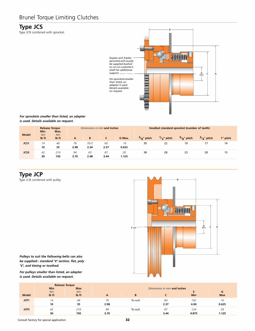
Type JCSType JCB combined with sprocket
CGMAX A
B
E MIN
Type JCPType JCB combined with pulley
Pulleys to suit the following belts can also
be supplied:- standard ‘V’ section, flat, poly
‘V’, and timing or toothed.
For pulleys smaller than listed, an adapter
is used. Details available on request.
For sprockets smaller than listed, an adapter
is used. Details available on request.
Release Torque Dimensions in mm and inches Smallest standard sprocket (number of teeth) Min. Max. Model Nm Nm lb ft lb ft A B C G Max. 3/8" pitch 1/2" pitch 5/8" pitch 3/4" pitch 1" pitch
JCS1 14 48 76 59.5 60 16 30 22 19 17 14
10 35 2.98 2.34 2.37 0.625
JCS3 42 210 94 63 87 28 38 28 23 20 15
30 150 3.70 2.48 3.44 1.125
Release Torque Min Max Dimensions in mm and inches Nm Nm E G Model lb ft lb ft A B C Min Max
JCP1 14 48 76 To suit 60 102 16
10 35 2.98 2.37 4.00 0.625
JCP3 42 210 94 To suit 87 124 28
30 150 3.70 3.44 4.875 1.125
CGMAX
A
B
Duplex and Triplexsprockets will usuallybe supplied bushed to run on customer’sshaft for additional support.
For sprockets smallerthan listed, an adapter is used.Details available on request.

33Consult factory for special application
Note:Ball bearing standard on model 1000. Ball bearing or bronze bush on model 550 depending on application requirement.
H Overload
movement
AEBDC
6 mm6 HOLES TAP J EQUISPACED
F
G
.236”
Brunel Torque Limiting Clutches
Normal Running
The drive is transmitted between the hub flange 1 and the drive flange 2 by the balls 4, spring-loaded into the pockets on the ball detent ring 3 secured by dowels.
Disengagement
On overload, the balls are displaced axially through the hub flange, further compressing the springs. Once out of their pockets, the balls roll on the face of the hub flange for one revolution before re-engaging and synchronizing the drive.
Torque Adjustment
The release torque is set by tightening nut 5 thus increasing the spring pressure. After setting, the nut is locked by a set screw.
Installation
Clutches can be supplied pilot bored or finish bored and keywayed. The hub may be fitted to either shaft and should be axially constrained against a shoulder to resist the resetting force and locked by means of a set screw onto the shaft key. The drive flange may be connected to a flexible coupling or can carry a sprocket or pulley.
Application
This type of protection is ideally suited to drives where it is essential to restart in the correct sequence and where access for manual resetting is not available.
1 Applicable to all variants.
Note: Type JBB clutches should always
be used with a limit switch to bring the
drive to rest within a few revolutions thus
preventing possible damage by continual
releasing and resetting.
Technical Features
• Instant release at pre-set torque
• Smooth hold-out for one revolution
• Means for motor switch-off
• Automatic self-engagement on restart
without loss of phasing
• Also available fitted with pulley (JBP)
• Rigid Coupling (JBR)
Release Torque 1 Dimensions in mm and inches Min Max Max Weight Nm Nm Speed kg Model lb ft lb ft rpm A B C D E Max E Min F G H J lb
JBB6 68 745 500 145 67 106f7 95 44 19 15 100 3 8
50 550 5.70 2.63 4.173 3.74 1.75 0.75 0.59 3.93 0.12 5/16-18 17.6
JBB7 338 1356 500 205 85 142f7 125 57 32 20 150 4 25
250 1000 8.07 3.34 5.591 4.92 2.25 1.25 0.78 5.9 0.16 7/16-14 55
Type JBB - Automatic ResetRelease Torque: 50 to 1000 Ib ft, 70 to 1356Nm

34Consult factory for special application
Brunel Torque Limiting Clutches
G
AEB
Ball bearing standard on Model JBS7. Ball
bearing or bronze bush on Model JBS6
depending on application requirement.
Duplex and Triplex sprockets will usually be
supplied bushed to run on customer’s shaft
for additional support.
For sprockets smaller than listed, an
adapter is used. Details on request.
Type JBSType JBB combined with chainwheel
Release Torque Dimensions in mm and inches Smallest standard sprocket (number of teeth) Min. Max. Model Nm Nm lb ft lb ft A B E Max E Min G 3/8" pitch 1/2" pitch 5/8" pitch 3/4" pitch 1" pitch
JBS6 68 745 145 67 44 19 85 40 31 26 22 18
50 550 5.70 2.63 1.75 0.75 3.34
JBS7 338 1356 205 80 57 32 130 51 40 32 28 22
250 1000 8.07 3.14 2.25 1.25 5.11
L NO OFF BOLTS
F
AEHKB
C
D
J
G
Type JBFType JBB combined with Brunel Eflex flexible coupling
Release Torque Dimensions in mm and inches Min. Max. Weight Model Nm Nm Kg
lb ft lb ft A B C D E Max E Min F G H Max H Min J K L lb
JBF6 68 745 145 145 40 25 44 19 105 5 58 16 22 80 4 23
50 550 5.70 5.70 1.57 0.98 1.75 0.75 4.13 0.19 2.28 0.63 0.87 3.15 51
JBF7 338 1356 205 195 65 30 57 32 155 5 90 32 25 120 6 40
250 1000 8.07 7.67 2.56 1.18 2.25 1.25 6.10 0.19 3.54 1.26 1.0 4.72 88

35
Brunel Power Modules
Limits Torque
Fast
Reliable
Easy to Install
Protect Equipment from:
• Overloads, Jams and Excess Torque
• Underloads, Run-dry, Cavitation
• Phase Loss, Phase Reversal, or Under-
voltage.
PTM-3 Programmable Load Monitor for any Electric Motor
• Absolutely limits torque to levels that you set.
• Detect trouble & provide early warning
• Protect machine, tools, & process• Optimize machine adjustments &
improve process quality• Reduce downtime & maintenance• Increase equipment output• Signal beginning or end of process
Benefits:Monitor:• Viscosity, Flow, Torque, Wear• Power Consumption, Load Profiles• Power Factor, Energy Usage• Equipment, Drivetrain, Process Data• Acquisition from Desktop PC View Real-Time & Plot: Watts, Amps, Volts, Power Factor, Frequency, HP, % Loads, Peak Loads. Remotely Set: Trip Levels, Delays
Typical Applications:• Pumps - blockage, run-dry cavitation protection• Mechanical drives - Immediate recognition of overload or underload• Conveyors and feeders - blockage protection• Grinding mills - feeder control and blockage protection
Features:• Front Panel programming & Actual Load Display• Up to three alarm limits• Analog or Digital output• Program and monitor unit remotely from PC• Accurate power transducer input for PLC/PC Controllers• Infra-red remote programming (optional)
PTM-3-4XL & PTM-3-4XLC 8FA 2
INDUSTRIAL CONTROL EQUIPMENT
36
Brunel Power Modules
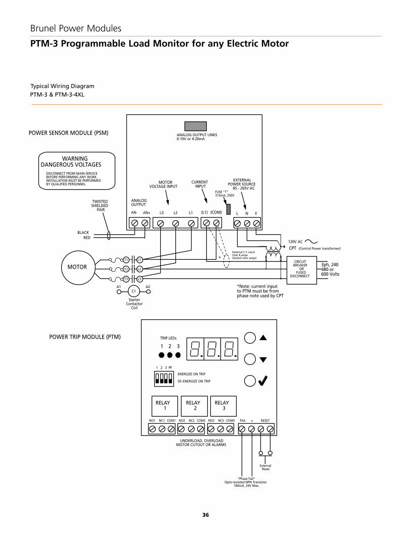
PTM-3 Programmable Load Monitor for any Electric Motor
Typical Wiring Diagram
PTM-3 & PTM-3-4XL
1 2 3
TRIP LEDs
RELAY1
RELAY2
RELAY3
NO1 NC1 COM1 NO2 NC2 COM2 NO3 NC3 COM3
ExternalReset
UNDERLOAD, OVERLOADMOTOR CUTOUT OR ALARMS
POWER SENSOR MODULE (PSM)
POWER TRIP MODULE (PTM)
DISCONNECT FROM MAIN SERVICE BEFORE PERFORMING ANY WORK. INSTALLATION MUST BE PERFORMED BY QUALIFIED PERSONNEL
WARNINGDANGEROUS VOLTAGES
1 2 3 PF
ENERGIZE ON TRIP
DE-ENERGIZE ON TRIP
"Phase Fail"Opto-Isolated NPN Transistor
100mA, 24V Max.
FAIL + RESET
C1A1
T1
T2
T3
ANALOGOUTPUT
MOTORVOLTAGE INPUT
CURRENTINPUT
EXTERNALPOWER SOURCE
85 - 265V AC
AN+ L3 L2 L1
MOTOR
L N E
BLACKRED
TWISTEDSHIELDED
PAIR
StarterContactor
Coil
A2
3 PH MAIN
CIRCUITBREAKER
ORFUSED
DISCONNECT
120V AC
L1
L2
L3
(L1) (COM)
FUSE "T"315mA, 250V
ANALOG OUTPUT LINKS0-10V or 4-20mA
*Note: current inputto PTM must be from phase note used by CPT
External C.T. req'dOver 8 amps (locked rotor amps)
CPT (Control Power transformer)
3ph, 240480 or 600 Volts
*
AN-

37
Brunel Power Modules
PTM-3 Specifications
Power Supply 85-264VAC 50-60Hz, 5W max.
Motor Voltage Single and Three Phase: 600V max.
Internal Current 5Amps max. (L1)for >5A use a standard external 5A secondary current transformer
Transformer
Frequency Range VFD Compatible 20-100 Hz
Accuracy Voltage ±2%, Current ±3%, Power ±5%
Analog Output 0-10V or 4-20mA (max. load 450)
Reaction Time 23ms actuation time or 19ms release time
Display 3 LED digits, 14.2 mm high, red
Displayed Values Load – calibrated to read 100 at normal running load
Status messages – start, stop, phase failure
Set-up values (i.e. trip levels).
Motor power, current and voltage
Trip Relays Three Form C Relays, contacts rated 10A @ 28VDC or 120VAC, 5A @ 240VAC
(May be switched to energize or de-energize on trip)
Trip Delays 0-25s in 0.1s increments
Trip Hold ON/OFF select, pushbutton reset, terminals for external
reset contacts
Start Delay 0-250s (0-9.9s in 0.1s increments; > 10s in 1s increments)
Phase Loss Output Opto-isolated NPN transistor, 100mA 24V max.
(Changes state if phase failure, 10% voltage drop, or phase sequence changes)
Enclosure NEMA 4X/IP66 Polycarbonate box with hinged clear cover. Enclosure can be drilled, sawed or punched on
bottom, sides or back for wiring access. Options: DIN rail adapter ‘G’ or 35mm ‘top hat’, open frame L
mounting bracket
Dimensions
Environment NEMA 4X / IP66, -4°F to +140°F (-20°C to +60°C)
200mm(H) x 120mm(W) x 90mm(D) Outside dimensions 7.87" 4.72" 3.54"
4.72 (120mm)
3.54 (90mm)
7.87 (200mm)
TRIPS
SET
POWER MODULE
1 2 3

38
Brunel Power Modules
PTM-4 Load Monitor
Features:
• Most cost-effective motor load protection. • Smallest unit available.
• Measures the motor active power.
• Internal Current Transformer. 1, 2, 4 & 8A motor current ranges.
• Single or three-phase motors.
• ‘Auto-Cal’ feature sets load reading to 100% with the motor running at normal load, together with default trip levels and hysteresis.
• Simple set-up of trip levels: greater than 100% = overload, less than 100% = underload.
• Easy ‘cloning’ of units.
• Diagnostic displays for Volts, Amps & Power.
• Intuitive display with simplified adjustment of parameters.
• Remote reset of latched relays.
• Analog output option: (4-20mA or 0-10V).
• Infra-red remote programming (optional)
TYPICAL WIRING DIAGRAMPTM-4
3 PH MAIN
600V 60Hz Max.MOTOR
CIRCUITBREAKER
ORFUSED
DISCONNECT
StarterContactor
Coil
C1A1 A2
T1
T2
T3
L1
L2
L3
L1 L2 L3CT+ CT-
1 2
V A P/Reset
C R1 R2A- A+ N LRS
A1C1
A2
WarningLight
Remote Trip Reset
Remote Trip Inhibit
Double Pole Double Throw monentary pushbotton
Relay C RI Normally Closed C R2 Normally Open
C1
RS
DISCONNECT FROM MAIN SERVICE BEFORE PERFORMING ANY WORK. INSTALLATION MUST BE PERFORMED BY QUALIFIED PERSONNEL
WARNINGDANGEROUS VOLTAGES
Analog OutputA-
*Note: Current Input to PTM-4Must be taken from phase notused by CPT (Control Power Transformer)
EXTERNALPOWER SOURCE
85 - 265V AC
120V ACNominal
CPT
External CT requiredif over 8 amps locked Rotor
*
RS
A+
A- for 1-10V outA+ for 4-20mA out
A- for 1-10V outA+ for 4-20mA out
Load meter
8FA 2
INDUSTRIAL CONTROL EQUIPMENT

39
Brunel Power Modules
PTM-4 Load Monitor Specifications
Power Supply 85-264VAC 50-60Hz, 5VA max.
Motor Voltage 600VAC max.
Motor Current Programmable: 1A, 2A, 4A, 8A.
Ranges (or >8A use an external 5A secondary current transformer).
Frequency 45-65Hz
Display Three 7 segment digits, 0.4in high, high intensity red.
Displayed Values Running: Load: (calibrated to read 100).
Stopped: Peak Load.
Status messages: Start, Stop.
Set-up: Trip Levels, Start & Trip delays, Hold ON/OFF
Diagnostics: Peak Load, Volts (RMS), Amps (RMS),
Watts or kW (auto-ranging),
Relays 2 contacts rated 10A @ 28VDC or 120VAC, 5A @ 240VAC. (Relay 1-NC, Relay 2-NO)
Trip Delays 0-25s in 0.1s increments.
Trip Hold (latch) ON/OFF select, pushbutton Reset, terminals for external Reset contacts
Start Delay 0-250s (0-9.9s in 0.1s increments)
Analog Output 0-10V or 4-20mA, max. load 450 Ohms (jumper selectable).
Option
Enclosure 1.772in (45mm) width x 3.071in (78mm) height x 4.606in (117mm) depth - Noral/Lexan - Gray (RAL 7035).
Wire sizes Upper terminals: 2x2.52mm (AWG 14) or 1x42mm (AWG 12).
Lower terminals: 1x2.52mm (AWG 14).
Mounting 35/36mm DIN rail. Optional front panel adapter, or NEMA 4X enclosure.
Environment Operating temperature: -4°F to + 122°F (-20°C to +50°C)
4.606(117mm)
3.071(78mm) 1.772
(45mm)
V
AP/Reset
1
2

40
Brunel Power Modules
Brunel Current Transformer
PTM-4 Mounting Bracket
CT Model
Current TransformerGeneral Purpose Compact Units, UR/cUR Recognized
Dimensions (inches)Part Number
(without brackets)
Window Size
(inches)
Current Rating
(Amperes) VA 60 HzVA 400
Hz
Accuracy(At Rated Current)
Rating Factor
30°C Ambient
A CEBH1
.20 DiameterMounting Hole
(2)
D CT-50 50:5 1.0 2.0 =2% 1.0CT-60 60:5 1.0 2.0 =2% 1.0CT-75 75:5 1.5 3.0 =2% 1.0CT-80 80:5 1.5 3.0 =2% 1.0
CT-100 100:5 2.0 4.0 =1% 1.0CT-120 1-1/8 120:5 2.5 5.0 =1% 1.0CT-125 125:5 2.5 5.0 =1% 1.0CT-150 150:5 2.5 5.0 =1% 1.0CT-200 200:5 2.5 5.0 =1% 1.0CT-250 250:5 2.5 5.0 =1% 1.0CT-300 300:5 2.5 5.0 =1% 1.0
CT Model A B C D E1.13 2.38 — .94 —

41
Brunel Proximity Sensors
Inductive Sensors
Housing Style Part Number FeaturesSensingRange
(mm) Output
18 mm - Embeddable Rotational SpeedMonitor, Potted-In Cable
IPSM185DC Uprox 5 3-Wire DC PNP
30 mm - Embeddable Rotational Speed Monitor, Potted-In Cable
IPSM3010DC Uprox 10 3-Wire DC PNP
Housing Style - Rectangular Part Number Features EmbeddableSensing Range
(mm) Output
14 mm - Embeddable/Nonembeddable, Potted-In Cable IP1420 20
Extruder Proximity Sensors
Waste Water Proximity Sensors
Housing Style Part Number Features ShieldedSensing Range
(mm)Output
ConfigurationSwitching
Frequency (Hz)
30 mm - Mini Quick-DisconnectIP3010NO Stainless Steel Yes 10 N.O. 15
IP3010NC Stainless Steel Yes 10 N.C. 12
Note 1: No ground pin on 12mm. Attach housing toground.
Note 2: Load can be switched to pin 2.

42
Brunel Proximity Sensors
Inductive Sensors
Housing Style Part Number FeaturesSensingRange
(mm) Output
30 mm - Embeddable, minifast Connection IP3015 Extended Range
15 2-Wire AC/DCShort-Circuit
Protected
Housing Style Part Number FeaturesSensing Range
(mm) Output
30 mm - Embeddable, Potted-In Cable IP3020 20 2-Wire AC/DCShort-CircuitProtection
IP3010 10 2-Wire AC/DC
Waste Water Proximity Sensors
Right Angle Cable for Quick-Disconnect Style Sensors Part Number Length (feet)
1.56 Green
4 1
23Red
Black
White1.78
RAC3 3
RAC6 6
RAC12 12
Accessories

43
Brunel Proximity Sensors
Inductive Sensors
High Speed Inductive Proximity Sensors
Housing Style Part Number Features SensingRange (mm) Output
12 mm - Embeddable, eurofast Connection HSIP1204 Stainless Steel 4 3-Wire DCPNP
18 mm - Embeddable, eurofast Connection HSIP1805 Stainless SteelFront Cap
5 3-Wire DCPNP
30 mm - Embeddable, eurofast Connection HSIP3010 Stainless SteelFront Cap
10 3-Wire DCPNP
Switches
Housing Style Part Number Features
Zero Speed Switch ZSS1R1 Speed Monitor - Single channel for over/under speed detection with start-up override, 120Vac.
Synchronization Monitor
SYNCMON1 K-System intrinsic safety barriers- Universal Logic Control - Single channel for speed, frequency, timer and syncronization applications with display, 24Vdc/120/
240Vac with display.

44
Pulse Stretcher Smart Plug
Dimensions Part Number Features
PULSESTRETCHER Red LED dispaly
Quick Disconnect Cordset
Style Part Number Features Length (inches) Used With
5-Pin Euro-style Cordset Double Ended DBLCS-5 Pin Euro Female Straight/ Male Straight 20 Flex Power ModuleExpandable I/O Module
5-Pin Mini-Style 5-Pin Cable Female Straight/Unterminated 72 AC Power Supplies
Brunel Proximity Sensors
Inductive Sensors
DC Sensor Power Supply
Power Supply Dimensions Part Number Supply Voltage Sensor Connection Supply/Output Cable
DCPOWERSPLY 105-130V AC 60 Hz 5-Pin Pigtail Euro-Style QD 5-Pin Mini QD
High Speed Inductive Proximity Sensors

45
Brunel Engineering Information
Torque Limiter Selection Checklist
Photocopy this page and complete thefollowing check list to ensure the correcttorque limiter selection is achieved, then fax it to: (940) 723-7888 or download this page at: www.brunelcorp.com/checklist and e-mail to [email protected]
Customer:
Project:
Prime mover:
(see page 42)
Service factor:
Driven equipment:
(see page 43)
Service factor:
Continuous power: Maximum power:
Operating speed: Overspeed:
Driving shaft diameter: Driven shaft diameter:
Driving shaft length: Driven shaft length:
Continuous misalignment: Transient misalignment:
Diameter constraints: Length constraints:
Distance between shaft ends: If indirect drive:
sprocket size/pulley size etc:
If you require help with torque limiter selections contact Brunel Corporation:Phone: (940) 723-7800 Fax: (940) 723-7888 E-mail: [email protected]

46
· From the continuous Power (Hp) and operating Speed (Rpm) calculate the Application Torque TNORM from the formula:
TNORM = 63,025 x (Hp/Rpm) lb-in
· Select Prime Mover Service Factor (Fp) from table.
· Select Driven Equipment Service Factor (Fm) from table.
· Calculate TMAX from the formula:
TMAX=TNORM (Fp + Fm)
· Select Torque Limiter such that TMAX < Torque Limiter Maximum Setting.· Check Rpm < Torque Limiter Maximum Speed (from catalog data).
· Check Torque Limiter Bore Capacity such that dmin < d < dmax.
· Consult the factory for alternatives if catalog limits are exceeded.
Brunel Engineering Information
Selection Procedure
TNORM = Application Torque (lb-in)
TMAX = Peak Application Torque (lb-in)
Hp = Continuous Power to be transmitted by torque limiter (hp)
Rpm = Speed of torque limiter application (rpm)
Fp = Prime Mover Service Factor
Fm = Driven Equipment Service Factor
dmax = Torque limiter maximum bore (in)
dmin = Torque limiter minimum bore (in)
Prime Mover Service Factors
Prime Mover Factors Fp
Diesel Engine 1 Cylinder *
2 Cylinder *
3 Cylinder 2.5
4 Cylinder 2.0
5 Cylinder 1.8
6 Cylinder 1.7
More than 6 Cylinder 1.5
Vee Engine 1.5
Gasoline Engine 1.5
Turbine 0
Electric Motor 0
Induction Motor 0
Synchronous Motor 1.5
Variable Speed*
Synchronous Converter (LCI) - 6 pulse 1.0
- 12 pulse 0.5
PWM/Quasi Square 0.5
Cyclo Converter 0.5
Cascade Recovery (Kramer, Scherbius) 1.5
*The application of these drive types is highly specialized and it is recommended that Brunel Corporation be consulted for further advice. The final selection should be made by Brunel Corporation.
For confirmation of torque limiter selectioncomplete the check list on page 41and fax to Brunel Corporation:Fax: (940) 723-7888
It is the responsibility of the system designer to ensure that the application of the torque limiter does not endanger the other constituent components in the system. Service factors given are an initial selection guide.
!WARNING
Selection Examples:
Waste Water Torque Limiter
Application: Torque Limiter applied between reducer
output shaft and drive sprocket
Prime mover: 1/2 Hp 4 pole induction motor 1750 Rpm
Driven equipment: chain & flight sludge conveyor system
Reducer: 925:1 ratio gear box
Reducer output speed = 1750 Rpm/925 ratio = 1.891 Rpm
TNORM = 63,025 X (Hp / Rpm) lb-in
= 63,025 X (.5 / 1.891)
= 16,664 lb-in
TMAX = TNORM (Fp + Fm)
16,664 (0 + 1.5)
TMAX = 24,996 lb-in
Choose: JSE1-0402EA
Torque Limiter Max Torque = 30,000 lb-in
Max Bore = 3.75"
Min Sprocket: H78 11 Tooth
Extruder Torque Limiter
Application: Torque Limiter applied between motor shaft
and reducer input shaft
Prime mover: 400 Hp DC drive 1750 max Rpm
Driven equipment: twin screw extruder
Motor shaft = 3 3/4"
GB shaft = 70mm
TNORM = 63,025 X (Hp / Rpm) lb-in
= 63,025 X (400 / 1750)
= 14,405 lb-in
TMAX = TNORM (Fp + Fm)
= 14,405 (0 + 1.15)
TMAX = 16,565 lb-in
Choose: JSE1-0128A
Torque Limiter Max Torque = 30,530 lb-in
Motor Rigid Hub Max Bore = 4.125"
Gearbox Flexible Hub Max Bore = 90mm

47
Brunel Engineering Information
Driven Equipment Service Factor
Application Load Service Factors Application Load Service Factors
Agitators Compressors
Liquids & Solids 1.40 Centrifugal 1.25
Liquids (Variable Density) 1.40 Lobe/Rotary 1.40
Pure Liquids 1.25 Reciprocating:
Semi-Liquids (Variable Density) 1.50 1 to 3 Cylinders 3.00
Blowers 4 or More Cylinders 1.75
Centrifugal 1.25 Conveyors - Uniformly Loaded or Fed
Lobe 1.50 Apron 1.25
Vane 1.25 Assembly 1.25
Brewing & Distilling Belt 1.25
Bottling Machinery 1.25 Bucket/Pan 1.25
Brew Kettles (Continuous Duty ) 1.25 Chain 1.25
Can Filling Machines 1.40 Flight 1.25
Cookers (Continuous Duty) 1.25 Live Roll 1.25
Mash Tubs (Continuous Duty) 1.25 Oven 1.25
Scale Hopper (Frequent Starts) 1.50 Screw 1.25
Can Filling Machines — Conveyors - Heavy Duty Not Uniformly Fed
Cane Knives — Apron 1.50
Car Dumpers — Assembly 1.50
Car Pullers -Intermittent Duty — Belt 1.50
Clarifiers 1.25 Bucket/Pan 1.50
Classifiers 1.50 Chain 1.50
Clay Working Machinery Dredge 1.50
Brick Press 2.00 Flight 1.50
Briquette Machine 2.00 Inclined Belt 1.50
Clay Working Machinery 1.40 Live Roll —
Extruders & Mixers 1.50 Oven 1.50
Pug Mills 1.40 Reciprocating 2.00
Coke Plants Screw 1.40
Pusher Rain Drive 2.50 Shaker 2.00
Door Opener 2.00 Cranes & Hoists
Pusher & Lorry Car Traction Drive 3.00 Bridge Drive 1.25
Cold Mills-Strip & Temper Mills 2.00 Main Hoists
Hot Mills-Strip & Sheet Mills 3.00 Medium Duty 1.40
Reversing, Blooming or Slabbing Mills — Heavy Duty 2.00
Edging Mills — Long or Cross Travel 1.75
Cooling Beds 1.50 Reversing 1.40
Drawbench 2.00 Skip Hoists 1.40
Furnace Pusher 2.00 Slope 1.75
Hot & Cold Saws 2.00 Trolley Drive 1.25
Ingot Curs 2.00 Crushers
Reelers 2.00 Ore 2.00
Straighteners 2.00 Stone 2.00
Seamless Tube Mills Piercer 3.00 Sugar 1.50
Rod Mills 3.00 Distilling (See Brewing)
Mill Tables 3.00 Crushers
Manipulators 3.00 Ore 2.00
Feed Rolls-Blooming Mills 3.00 Stone 2.00
Sugar 1.50

48
Brunel Engineering Information
Driven Equipment Service Factor
Application Load Service Factors Application Load Service Factors
Dredgers Laundry Tumblers 1.50
Cable Reels — Laundry Washers
Conveyors 1.40 Reversing 1.40
Cutter Head Drives 2.00 Line Shafts
Jig Drives 2.00 Heavy Shock Load 2.00
Maneuvering Winches — Moderate Shock Load 1.40
Pumps 1.40 Uniform Load 1.40
Screen Drive 2.00 Lumber Industry
Stackers 1.40 Conveyors - Burner 2.00
Utility Winches — Conveyors - Main or Heavy Duty 2.00
Elevators Conveyors - Main Log 2.00
Bucket - Uniform Load 1.25 Conveyors - Merry-Go-Round 2.00
Bucket - Heavy Load 1.50 Conveyors - Slab 2.00
Bucket - Continuous 1.40 Conveyors - Transfer 2.00
Centrifugal Discharge 1.50 Conveyors - Waste 1.40
Escalators 1.40 Chains - Floor 2.00
Freight 1.50 Chains - Green 2.00
Gravity Discharge 1.25 Cut-Off Saws - Chain 2.00
Passenger Service - Hand Lift — Cut-Off Saws - Drag 2.00
Fans Debarking Drums 2.00
Centrifugal 1.25 Feeds - Edger 2.00
Cooling Towers - Induced Draft 1.40 Feeds - Gang 2.00
Induced Draft with Damper 1.50 Feeds - Trimmer 2.00
Induced Draft without Control 2.00 Log Deck 2.00
Large (Mine, etc.) 1.40 Log Hauls - Incline Well Type 2.00
Large Industrial 1.50 Log Turning Devices 2.00
Light (Small Diameter) 1.25 Planer Feed 2.00
Feeders Planer Tilting Hoists 2.00
Apron 1.50 Rolls - Live - Off Brg. - Roll Cases 2.00
Belt 1.50 Sorting Table 2.00
Disc 1.25 Tipple Hoist 2.00
Reciprocating 2.00 Transfer - Chain 2.00
Screw 1.50 Transfer - Craneway 2.00
Food Industry Tray Drives 2.00
Beet Industry 1.50 MachineTools
Bottling 1.40 Bending Roll 1.40
Can Filling 1.40 Plate Planer 2.00
Cereal Cooker 1.25 Punch Press - Gear Driven 2.00
Dough Mixer 1.50 Tapping Machines 2.00
Meat Grinders 1.50 Other Machine Tools:
Generators (Not Welding) Auxillary Drives 1.25
Even Load 1.00 Main Drives - Uniform Load 1.50
Hoist & Railway Service 1.50 Main Drives - Heavy Duty 2.00
Weldger Load 2.00 Metal Mills
Hammer Mills 2.50 Bending 1.50
Hoists Bridle Roll Drives 2.00
Heavy Duty 2.00 Draw Bench - Carriage 1.50
Medium Duty 1.50 Draw Bench - Main Drive 1.50
Skip Type 1.50 Forming Machines 2.00
Kiln 2.00 Hammers 2.00

49
Application Load Service Factors Application Load Service Factors
Metal Mills (cont.) Paper Mills (cont.)
Presses 2.00 Dryers 1.25
Punching 2.00 Felt Stretcher 1.50
Shears 1.50 Felt Whipper 2.00
Slitters 1.40 Jordans 1.40
Straighteners 2.00 Presses 1.40
Table Conveyors: Pulp Machines (Reel) 1.40
Non-Reversing 2.00 Screens (Chip & Rotary) 1.50
Reversing 2.00 Stock Chests 1.40
Winding Reels - Strip 2.00 Suction Roll 1.40
Wire Drawing & Flattening Machine 2.00 Thickeners (AC) 1.40
Wire Winding Machine 1.40 Washer (AC) 1.40
Mills - Rotary Type Winders (Surface Type) 1.40
Ball 2.00 Plastic
Dryers & Coolers 1.40 Calenders 1.50
Kilns 1.40 Crushers 1.50
Pebble 2.00 Extruders Single Screw (Variable Speed) 1.50
Rod/Tube 2.00 Extruders Single Screw (Fixed Speed) 1.75
Tumbling Barrels 2.00 Extruders Twin Screw (Variable Speed) 1.15
Mixers Printing Presses 1.40
Concrete Mixers (Continuous) 1.50 Pullers
Concrete Mixers (Intermittent) 1.50 Barge Haul 2.00
Constant Density 1.25 Pulverisers
Drum 1.50 Roller/Hammer Mill (Light Duty) 1.50
Variable Density 1.40 Hog/Hammer Mill (Heavy Duty) 1.75
Grizzly 2.00 Pumps
Oil Industry Centrifugal 1.40
Chillers 1.50 Descaling with Accumulators 1.25
Oil Well Pumping — Proportioning 1.40
Paraffin Filter Press 1.50 Rotary Gear
Rotary Kilns 1.50 Lobe 1.25
Paper Mills Vane 1.25
Aerators — Reciprocating:
Agitators (Mixers) 1.50 1 Cylinder (Single or Double Acting) 3.00
Agitators (Pure Liquid) 1.25 2 Cylinders (Single Acting) 2.00
Barker Auxiliaries (Hydraulic) 2.00 2 Cylinders (Double Acting) 1.75
Barker (Mechanical) 2.00 3 Cylinders or More 1.50
Beater & Pulper 1.50 Rubber Industry
Bleacher 1.25 Batch Mixers 1.75
Calenders 1.40 Continuous Mixers 1.50
Calenders - Super 2.00 Extruders (Continuous) 1.50
Chemical 1.25 Extruders (Intermittent) 1.75
Chipper 2.00 Plasticator 2.50
Chip Feeder 1.50 Rubber Calender 1.40
Converting Machines (expect Cutters, Platers) 1.40 Rubber Mill (2 or More) 1.40
Conveyors (Chips/Barks) 1.40 Sheeter 1.40
Conveyors (Log) 2.00 Tire Building Machines —
Couch/Coating Rolls 1.25 Tire & Tube Press Openers —
Cutters (Platers) 2.00 Tubers & Strainers 1.40
Cylinders 1.50
Brunel Engineering Information
Driven Equipment Service Factor

50
Brunel Engineering Information
Driven Equipment Service Factor
Application Load Service Factors Application Load Service Factors
Sewage Disposal Equipment Textile Industry
Aerators 1.50 Batcher 1.50
Bar Screens 1.50 Dyeing Machinery 1.50
Chemical Feeders 1.25 Calender 1.50
Collectors (Circuline/Straightline) 1.25 Cards 1.50
Dewatering Screws 1.50 Card Machine 2.00
Grit Collectors 1.40 Dry Can 1.50
Scum Breakers 1.50 Dryers 1.50
Slow or Rapid Mixers 1.50 Loom 1.50
Sludge Collectors 1.40 Mangles 1.50
Thickeners 1.50 Nappers 1.50
Vacuum Filters 1.50 Pads 1.50
Screens Range Drives —
Air Washing 1.25 Slashers 1.40
Rotary (Stone or Gravel) 1.50 Soapers 1.50
Traveling Water Intake 1.25 Spinners 1.50
Skip Hoists — Tenner Frames 1.50
Slab Pushers Washers 1.50
Steering Gear 1.50 Winders 1.50
Stokers 1.50 Tobacco & Cigarette Machinery 1.50
Slitters — Tumbling Barrels 2.00
Steel Industry 1.50 Waste Water Treatment
Soaking Pit/Cover Drive: Chain & Flight Systems 1.50
Lift 1.00 Aerators 1.50
Coilers (Up or Down) Cold Mills Only 1.50 Screw Pumps 1.50
Coilers (Up or Down) Hot Mills Only 2.00 Screens 1.50
Travel 2.00 Windlass 1.50
Stokers 1.25 Wood Working Machinery
Sugar Industry Trimmers 2.00
Cane Carrier & Leveller 1.75 Haulage 2.00
Cane Knife & Crusher 2.00 Barkers 2.00
Mill Stands Turbine Driven-Helical/Herringbone Gears 1.50 Planes 2.00
Electric Drive or Steam Driven with all
Helical/Herringbone or Spur gears with any prime
mover
1.75 Saws 2.00
Example:
Metal Mill Straightener T= DC Drive HP x 5,252 x 2 Service Factor
= RPM
Minimum Torque Setting (lb-in)
T = NORM = Hp x 63025
Rpm
TMAX = TNORM (Fp + Fm)
TMAX = TNORM ( 0 + 2 ) = Hp x 63025 x2
Rpm

51
Belt Length
To determine the belt length to use for a drive when the center distance and wheel diameters are known:
C = Center Distance
D = Large Wheel Diameter
d = Small Wheel Diameter
Belt Length = 2C + 1.57(D + d) + (D - d)2
4C
Belt Speed
FPM = Diameter (Inches) x RPM x .262
Center Distance
To determine the actual center distance (C) on which a given drive will operate:
L = Belt Length
D = Large Wheel Diameter
d = Small Wheel Diameter
A = L – 1.57 (D + d)
Factor h – from the following chart
D - d
A h
D - d
A h
D - d
A h
D - d
A h
0.00 0.00 0.16 0.08 0.30 0.16 0.43 0.24
0.02 0.01 0.18 0.09 0.32 0.17 0.44 0.25
0.04 0.02 0.20 0.10 .034 0.18 0.46 0.26
0.06 0.03 0.21 0.11 .035 0.19 0.47 0.27
0.08 0.04 0.23 0.12 0.37 0.20 0.48 0.28
0.10 0.05 0.25 0.13 0.39 0.21 0.50 0.29
0.12 0.06 0.27 0.14 0.40 0.22 0.51 0.29
0.14 0.07 0.29 0.15 0.41 0.23
C = [ A - h (D - d) ]
2
Force (W) Lbs.
Horsepower (HP) and Velocity (V) Feet Per Minute W = 33,000 x HP
V
Horsepower
Horsepower (HP) is the rate of doing work. One HP is equal to raising 33,000 lbs. one foot in one min.
Force (W) lbs and Velocity (V) Feet per Minute HP = W x V
33,000
Torque (T) lb-in and Revolutions Per Minute (RPM) HP = T x RPM
63,025
Torque (T) lb-ft and Revolutions Per Minute (RPM) HP = T x RPM
5,252
Kilowatts to HP
HP = Kilowatts x 1.341
Pitch Diameter (D) of Gear or Sprocket
Velocity (V) Feet Per Minute and Revolutions Per Minute (RPM)
D = V
.2618 x RPM
Revolutions Per Minute
Velocity (V) Feet Per Minute and Pitch Diameter (D) or Gear or Sprocket – Inches
RPM = FPM
.262 x D
Horsepower (HP) and Torque (T) lb-in RPM = 63,025 x HP
T
Torque
Torque (T) is a turning movement or twisting effort.
T (lb-in) = 63,025 x HP
RPM
T (lb-ft) = 5,252 x HP
RPM
Horsepower (HP) and Revolutions Per Minute (RPM)
T (lb-in) = Force (lb) x Lever Arm (in)
T (lb-ft) = Force (lb) x Lever Arm (ft)
T (lb-ft) = Nm x .7376
Velocity (V) Feet Per Minute
Pitch Diameter (D) of Gear or Sprocket – Inches and Revolutions Per Minute (RPM)
V = .2618 x D x RPM
Brunel Engineering Information
Application Formulas

52
Brunel Engineering Information
Metric Conversion Chart
MULTIPLY BY TO OBTAIN
LENGTH
Millimeter .03937 Inch
Centimeter .3937 Inch
Meter 39.37 Inch
Inch 2.54 Centimeter
Feet 30.48 Centimeter
Feet .3048 Meter
ROTATION
RPM .1047 Rad./Sec.
RPM 6.00 Degrees/Sec.
Degrees/Sec. .1667 RPM
Rad./Sec 9.549 RPM
VELOCITY
Centimeter/second .3937 Inches/Second
Centimeter/second 1.969 Feet/Minute
Meter/second 3.281 Feet/Second
Meter/second 196.9 Feet/Minute
Meter/second 2.237 Miles per hour
Inch/second 25.4 Millimeters/Second
Inch/second 2.54 Centimeters/Second
Foot/second .3048 Meters/Second
Foot/minute .00508 Meters/Second
VOLUME
Centimeter3 .0610 Inches3
Centimeter3 .034 Fluid Ounce
Liter 61.02 Inches3
Liter .0353 Feet3
Liter .264 U.S. Gallon
Inch3 16.39 Centimeter3
Feet3 28.32 Liter
Gallon 3.785 Liter
WEIGHT
Gram .03527 Ounce
Kilogram 35.27 Ounce
Kilogram 2.205 Pounds
Ounce 28.35 Grams
Pound 453.6 Grams
MULTIPLY BY TO OBTAIN
AREA
Millimeters2 .00155 Inches2
Centimeters2 .155 Inches2
Meters2 10.76 Feet2
Inches2 645.16 Millimeters2
Inches2 6.452 Centimeters2
Feet2 929.03 Centimeters2
Feet2 .0929 Meters2
DENSITY
lg/cm3 .03613 Lb/In3
lg/cm3 62.43 Lb/Ft3
lb/in3 27.68 Gr/Cm3
lb/ft3 .016 G/Cm3
lb/ft3 16.02 Kg/M3
MOMENT OF INERTIA
Newton-Meters2 2.42 Lb. Ft.2
Oz.-In.2 .000434 Lb. Ft.2
Lb.-In.2 .00694 Lb. Ft.2
Slug-Ft.2 32.17 Lb. Ft.2
Oz.-In.-Sec.2 .1675 Lb. Ft.2
Lb.-In.-Sec.2 2.68 Lb. Ft.2
POWER
Joule/sec .001341 Horsepower
Kilocalorie/hour 3.967 BTW/Hour
Horsepower .33000 Lb. Ft./Min.
Horsepower 746 Watts
BTU/hour .2521 Kilocalorie/Hour
Watts .00134 Horsepower
TORQUE
Newton-meter 8.84 Lb. In.
Lb. In. .113 Newton-Meter
Lb. Ft. 1.3558 Newton-Meter
Lb. Ft. 12 Lb. In.

53
Brunel Corporation
Warranty
Brunel Corporation guarantees all products will leave the factory in good condition. We warranty our products against defects in workmanship and material for a period of 365 days (one year) after shipment. Adjustments under this warranty will be made only after completion of inspection of the part or product in the factory. Liability under the warranty shall extend only to the replacement or correction of any part or product determined by Brunel Corporation inspection as not conforming to this warranty. All materials must be returned freight prepaid.
This warranty shall not apply to any product which shall have been repaired or altered without the manufacturer’s knowledge and consent or operated or installed contrary to instruction or subjected to misuse, improper maintenance or damaged by accident or negligence.
This warranty is made in lieu of all other warranties, express or implied, including merchantability or fitness for a particular purpose, and there are no other warranties that extend beyond this express warranty.
Brunel Corporation reserves the right to discontinue models or to change specifications at any time without notice. No discontinuance or change shall create any liability on the part of Brunel in respect to its products in the hands of its customers or products on order not incorporating such change even though delivered after any such change.
Rotating equipment is potentially dangerous and should be properly guarded. The user should check for all applicable safety codes in his area and provide a suitable guard.
Performance Assurance
Rated torque and speeds of Brunel Corporation products are provided in current catalogs to assist the buyer in selecting the proper Brunel Corporation product. In addition, application assistance is offered by Brunel Corporation for guidance to the buyer in selection of a catalog product and application of custom designed products. Since the actual performance characteristics of all Brunel Corporation products in the buyer’s application are the responsibility of the buyer, performance assurance is usually accomplished through manufacture of a prototype by Brunel Corporation, and a test or qualification program on the part of the buyer.

For catalogs and/or technical assistance:
1304 Twin Oaks StreetWichita Falls, Texas 76302
Phone: (940) 723-7800Fax: (940) 723-7888
E-mail: [email protected]: brunelcorp.com
Product Catalog
Bru
nel C
orp
oratio
n Pro
du
ct Catalo
g2010 World Leader in Modular Torque Limiters