brio 36 installation manual - calrec 36... · rear connections 12 expansion options 13 ... hx7 8ez,...
TRANSCRIPT

calrec.com Putting Sound in the Picture
Audio Production System with Optional Networking
BRIO 36 INSTALLATION MANUAL

Calrec Audio LtdNutclough MillHebden BridgeWest YorkshireEngland UKHX7 8EZ
Tel: +44 (0)1422 842159Fax: +44 (0)1422 845244Email: [email protected]
calrec.com
No part of this manual may be reproduced
or transmitted in any form or by any means,
electronic or mechanical, including photocopying
and scanning, for any purpose, without the prior
written consent of Calrec Audio Ltd.
Whilst the Company ensures that all details in this
document are correct at the time of publication,
we reserve the right to alter specifications and
equipment without notice. Any changes we make
will be reflected in subsequent issues of this
document. The latest version will be available
upon request. This publication is for International
usage.
Calrec Audio Ltd reserve the right to change
specifications without notice. E & O.E.
The established policy of Calrec Audio
Ltd. is to seek improvements to the design,
specifications and manufacture of all products.
It is not always possible to provide notice outside
the company of the alterations that take place
continually.
Despite considerable effort to produce up to
date information, no literature published by
the company nor any other material that may
be provided should be regarded as an infallible
guide to the specifications available nor does
it constitute an offer for sale of any particular
product.
Apollo, Artemis, Summa, Brio 36, RP1, Hydra
Audio Networking and Bluefin High Density
Signal Processing (HDSP) are trade marks of
Calrec Audio Ltd. Dolby®E is a registered trade
mark of Dolby Laboratories, Inc. All other trade
marks are acknowledged.
© 2017 Calrec Audio Ltd. All Rights Reserved.

BRIO 36CONTENTSInformation� 5Information� 6Health�and�Safety� 8Package�Contents� 9
Getting�Started� 11Rear�Connections� 12Expansion�Options� 13
Expansion�I/O�cards� 13
Optional�Hydra�2�Module� 13
Hydra�I/O�Box�IDs� 14ID�configurations� 14
Changing�an�I/O�Box’s�HID� 14
Port�Labels�and�SW-P-08�Settings� 14
Duplicate�HIDs� 14
Spare/Replacement�I/O�Boxes� 14
Setting�Hydra�IDs�for�Fixed�Format�I/O�� 15Address�2� 15
Extended�ID�Addressing� 15
Setting�Hydra�IDs�for�Modular�I/O�� 16Connecting�Brio�36�to�the�Hydra2�Network� 17Hardware�Power�Connections� 18Setting�the�Date�and�Time� 19Connecting�a�Laptop�to�Brio�36� 20Configuring�LAN�Ports� 21Software�Updates� 22
Control�Surface� 23Surface�Measurements� 24Component�Connections� 26Surface�Layout� 27Headphone�and�Talkback�Microphone� 28
Headphone�and�Talkback�Microphone�Connections� 28
Power�Supply�Units� 29Disconnecting�the�PSUs� 29
Power�Distribution� 29
Connection�Information� 31Synchronisation� 32
Synchronisation�at�different�sample�rates:� 32
Audio�I/O�Connections� 33Built-In�Audio�Interfaces� 33
Power� 33
ID�configuration� 33
Modular�I/O�card�slots� 33
Hydra2�connection� 33
Small�Form-Factor�Pluggable�(SFP)�Overview�� 36SFP�slot�orientation� 36
SFP�latching�and�extraction� 37
SFP�slot�covers� 37
Loose�SFP�storage� 37
Copper�SFP�Connectivity� 38Shielded�cables�and�connectors� 38
Maximum�cable�length� 38
Cable�routing�considerations� 38
Termination�-�strain�relief� 38
Termination�-�pin-out� 39
Testing/certification� 39
Temporary�/�reusable�cables� 39
Fibre�SFP�Connectivity� 40Singlemode�vs�Multimode� 40
Identification� 40
Duplex�Connectors�/�Terminations� 40
Single�Strand,�Bi-Directional�SFPs� 40
SFP�Fibre�Specifications� 40
Fibre�-�General�Rules� 42Testing�/�Certification� 42
Areas�of�Loss� 42
Fibre�Handling�Practise� 42
Ruggedised�Fibre� 42
Cleaning�and�Preventative�Maintenance� 42
Cleaning�Fibre�Optic�Cables�and�Connectors� 43
Cleaning�Procedure� 43
Additional�Notes� 43
Cleaning�Optical�Transceivers� 43
Cleaning�Procedure� 43

4 BR IO 36 Audio Production System with Optional Networking
GPIO�Connections� 44GPI�(inputs)� 45
GPO�(outputs)� 45
Dry�closure�only�outputs� 45
Remote�Control�and�Production�Automation� 49SW-P-08�Source�to�Destination�Router�Remote�Control� 50
Network�Connection�&�Redundancy� 50
Brio�36�Connection�configuration� 50
SW-P-08�I/O�mapping�configuration� 50
Ember�Remote�Control� 51Brio�36�Connection�configuration� 51
Remote�Control–Calrec�Serial�Control�Protocol�� 52CSCP�versions� 52
Faders�controlled�by�CSCP� 52
Controls�available�via�CSCP� 52
Connection� 52
Connecting�via�Corporate�LAN� 52
Brio�36�Connection�configuration� 52
BR-IO���External�I/O�Rack� 55External�I/O�Rack�for�Brio�36� 56
External�I/O�Rack�Audio�Interfaces� 56
Port�Patching�Identification� 56
Hydra2�interfacing� 56
BR-IO�box�ID�setting� 57
BR-IO�box�Power�Supply� 57
Disconnecting�the�PSUs� 57
Reference�to�Power�/�Environmental�Specification� 57
Specifications� 59General�Specifications� 60Power/Environmental�Specifications� 61Audio�Performance�Specification� 64
calrec.com Putting Sound in the Picture
BRIO 36INFORMATION

6 BR IO 36 Audio Production System with Optional Networking Information
INFORMATION
Should you require any technical assistance with your Calrec product please contact your regional Calrec distributor. Customers within the UK or Ireland should contact Calrec directly.
For a complete list of worldwide distributors by region, go to www.calrec.com or contact us for more information.
Our�UK�customer�support�team�works�closely�with�our�global�distributor�network�to�provide�the�highest�level�of�after�sales�support.��Your�distributor�should�be�your�first�point�of�contact�and�will�often�be�able�to�provide�an�instant�solution,�be�it�technical�advice,�spares�or�a�site�visit�by�an�engineer.�
Product�WarrantyA�full�list�of�our�conditions�and�warranties�relating�to�goods�services�is�contained�in�Calrec’s�standard�terms�and�conditions.���A�copy�of�this�is�available�on�request.
RepairsIf�you�need�to�return�goods�to�Calrec�for�whatever�reason,�please�contact�your�regional�distributor,�or�Calrec�customer�support�beforehand�for�guidance,�as�well�as�to�log�the�details�of�the�problem�and�receive�a�reference�number.��
For�customers�outside�the�UK�and�Ireland,�shipping�via�the�distributor�saves�customers�from�dealing�with�exportation�paperwork.��If�there�is�a�need�to�send�direct�to�Calrec,�contact�us�beforehand�to�log�the�incoming�repair�and�for�assistance�with�exportation�documents.
Standard�of�ServiceEnsuring�the�highest�standards�is�a�priority,�if�you�have�any�comments�on�the�level�of�service,�product�quality�or�documentation�offered�to�you�by�Calrec,�please�contact�the�Calrec�Customer�Support�team�in�the�UK�who�will�endeavour�to�address�your�issues.��Calrec�welcomes�all�customer�feedback.
For�feedback�specific�to�this�document,�please�contact�[email protected].
Whenever you contact Calrec Customer Support please have the following information to hand:
•� Name.•� Company.•� Email�Address.•� Full�details�of�enquiry�(e.g.�fault�report).•� Serial�number�of�faulty�hardware�(if�
applicable).
Once�this�information�has�been�provided,�a�service�ticket�will�be�created�to�log�your�enquiry.��The�service�ticket�reference�number�will�be�given�via�email.
Serial�NumbersAll�units�produced�by�Calrec�are�given�a�serial�number�and�are�booked�into�a�central�record�system�at�the�time�of�manufacture.��These�records�are�updated�whenever�a�piece�of�hardware�is�dispatched�to�or�received�from�a�customer.
When�contacting�Calrec�Customer�Support�with�a�hardware�inquiry�it�is�important�that�the�correct�Calrec�serial�number�is�provided�to�enable�the�customer�support�team�to�provide�a�high�level�of�service.��Brio�36�serial�numbers�can�be�found�on�the�label�on�the�rear�of�the�chassis�as�shown�below.
After�Sales�ModificationsPlease�be�aware�that�any�modifications�other�than�those�made�or�approved�by�Calrec�Audio�Limited�or�their�agents,�may�invalidate�the�console’s�warranty.��This�includes�changes�to�cabling�provided�by�Calrec�and�variations�to�the�recommended�installation�as�detailed�in�Calrec�documentation.
Modifications�to�this�equipment�by�any�party�other�than�Calrec�Audio�Limited�may�invalidate�EMC�and�safety�features�designed�into�the�equipment.��Calrec�Audio�Limited�can�not�be�liable�for�any�legal�proceedings�or�problems�that�may�arise�relating�to�such�modifications.�
If�in�doubt,�please�contact�Calrec�Audio�Limited�for�guidance�prior�to�commencing�any�modification�work.
Telephone: (9:00am-5.30pm) +44 (0) 1422 842159
Email - Technical: [email protected]
Email - General: [email protected]
Postal Address:
Calrec Audio Ltd.Nutclough Mill,Hebden Bridge,West Yorkshire,HX7 8EZ,UK
Fax: +44 (0) 1422 842159
Website: www.calrec.com
EXAMPLE OF LABEL ON REAR OF CHASSIS SHOWING SERIAL NUMBER

CA LREC Putting Sound in the Picture 7
InstallationIn�many�installations�the�AC�power�connectors�will�not�be�readily�accessible,�effectively�making�the�equipment�permanently�connected.��The�installation�should�be�carried�out�in�accordance�with�all�applicable�installation�rules�and�regulations.
Service�PersonnelThe�AC�power�disconnect�devices�are�the�2�x�IEC�(IEC60320-1�C13/C14)�couplers�located�at�the�rear�of�each�unit.�WARNING:�The�apparatus�has�a�dual�power�system.��It�is�essential�that�BOTH�AC�power�IEC�couplers�are�disconnected�to�prevent�exposure�to�hazardous�voltage�within�the�unit.
Third�Party�EquipmentIntegrating�third�party�equipment�into�a�Calrec�system�may�compromise�the�product’s�ability�to�comply�with�the��radiated�emission�limits�set�in�the�EMC�(Electro�Magnetic�Compatibility)�standard�EN55022.�
Calrec�Audio�Limited�can�not�be�responsible�for�any�non-conformities�due�to�use�of�third�party�equipment.��If�in�doubt,�please�contact�Calrec�Audio�Limited�for�guidance�prior�to�integrating�any�third�party�equipment.
ESD�(Static)�Handling�ProceduresIn�its�completed�form,�this�equipment�has�been�designed�to�have�a�high�level�of�immunity�to�static�discharges.��However,�when�handling�individual�boards�and�modules,�many�highly�static�sensitive�parts�are�exposed.�In�order�to�protect�these�devices�from�damage�and�to�protect�your�warranty,�please�observe�static�handling�procedures,�for�example,�use�an�appropriately�grounded�anti-static�wrist�band.��
All�modules�and�cards�should�be�returned�to�Calrec�Audio�Limited�in�anti-static�wrapping.��Calrec�Audio�Limited�can�supply�anti-static�wrapping�upon�request.�
This�applies�particularly�to�digital�products�due�to�the�types�of�devices�and�very�small�geometries�used�in�their�fabrication,�analogue�parts�can,�however,�still�be�affected.
RoHS�LegislationIn�order�to�comply�with�European�RoHS�(Reduction�of�Hazardous�Substances)�legislation,��Calrec�PCB�and�cable�assemblies�are�produced�with�lead-free�(tin/copper/silver)�solder�instead�of�tin/lead�solder.
In�the�unlikely�event�of�a�customer�having�to�carry�out�any�re-soldering�on�any�Apollo,�Artemis,�Summa,�Brio�36�or�Hydra2�hardware,�it�is�imperative�that�lead-free�solder�is�used;�contaminating�lead-free�solder�with�leaded�solder�is�likely�to�have�an�adverse�effect�on�the�long-term�reliability�of�the�product.��Circuit�boards�assembled�with�lead-free�solder�can�be�identified�(in�accordance�with�IPC/JEDEC�standards)�by�a�small�oval�logo�(see�below)�on�the�top-side�of�the�circuit�board�near�the�PCB�reference�number�(8xx-xxx).��The�same�logo�is�used�on�the�connector�hoods�of�soldered�cable�assemblies.�
If�in�doubt,�please�check�with�a�Calrec�customer�support�engineer�before�carrying�out�any�form�of�re-soldering.
UKAS AND ANAB REGISTRATION
LEAD FREE STICKERLEAD FREE
ISO�9001�and�RAB�RegisteredCalrec�Audio�Ltd�has�been�issued�the�ISO9001:�2008�standard�by�the�Governing�Board�of�ISOQAR.
The�award,�for�both�UKAS�and�RAB�registration�(see�below),�is�the�most�comprehensive�of�the�ISO9000�international�standards.��Granted�in�recognition�of�excellence�across�design,�development,�manufacture�and�after-sales�support,�the�certification�follows�a�rigorous�and�thorough�review�of�Calrec’s�internal�and�external�communication�and�business�procedures.

8 BR IO 36 Audio Production System with Optional Networking Information
HEALTH AND SAFETY
Important�Safety�Instructions:•� Read�these�instructions.•� Keep�these�instructions.•� Heed�all�warnings.•� Follow�all�instructions.•� Do�not�use�this�apparatus�near�water.•� Do�not�block�any�ventilation�openings.�
Install�in�accordance�with�the�manufacturer’s�instructions.
•� Do�not�install�near�any�heat�sources�such�as�radiators,�heat�registers,�stoves,�or�other�apparatus�(including�amplifiers)�that�produce�heat.
•� Protect�the�power�cord�from�being�walked�on�or�pinched�particularly�at�the�plugs,�convenience�receptacles,�and�the�point�where�they�exit�from�the�apparatus.
•� Use�only�with�the�cart,�stand,�tripod,�bracket,�or�table�specified�by�the�manufacturer,�or�sold�with�the�apparatus.���When�a�cart�is�used,�use�caution�when�moving�the�cart/apparatus�combination�to�avoid�injury�from�tip-over.
•� Refer�all�servicing�to�qualified�service�personnel.��Servicing�is�required�when�the�apparatus�has�been�damaged�in�any�way,�such�as�power-supply�cord�or�plug�is�damaged,�liquid�has�been�spilled�or�objects�have�fallen�into�the�apparatus,�the�apparatus�has�been�exposed�to�rain�or�moisture,�does�not�operator�normally,�or�has�been�dropped.
•� Warning:�To�reduce�the�risk�of�fire�or�electric�shock,�do�not�expose�this�apparatus�to�rain�or�moisture.
•� Not�intended�for�outdoor�use.•� This�equipment�must�be�EARTHED.�•� Before�starting�any�servicing�operation,�
equipment�must�be�isolated�from�the�AC�power�supply.��The�disconnect�devices�are�the�2�x�IEC�connectors�(IEC�60320-1�C13/C14�couplers).
•� Do�not�allow�ventilation�slots�to�be�blocked.�
•� Do�not�leave�the�equipment�powered�up�with�the�dust�cover�fitted.
CleaningFor�cleaning�the�front�panels�of�the�equipment�we�recommend�using�a�soft�anti-static�cloth,�lightly�dampened�with�water�if�required.
Explanation�of�Warning�SymbolsTriangular�warning�symbols�contain�a�black�symbol�on�a�yellow�background,�surrounded�by�a�black�border.
The�lightning�flash�with�arrow�head�symbol�within�an�equilateral�triangle,�as�shown�on�this�page,�is�intended�to�alert�the�user�to�the�presence�of�dangerous�voltages�and�energy�levels�within�the�product’s�enclosure�that�may�be�of�sufficient�magnitude�to�constitute�a�risk�of�electric�shock�or�injury.
The�exclamation�mark�within�an�equilateral�triangle,�as�shown�on�this�page,�is�intended�to�prompt�the�user�to�refer�to�important�operating�or�maintenance�instructions�in�the�documentation�supplied�with�the�product.
EarthingThis�is�a�Class�I�product.�An�Earth�connection�MUST�be�provided�in�each�AC�power�cord.
The�Earth�Bolt�connection�at�the�rear�of�the�console�is�provided�for�those�users�who�wish�to�have�a�separate�ground/earth��connection�using�Earth�cable�at�least�6�mm2�in�cross�section�(10�AWG),�this�connection�is�optional�and�is�NOT�a�requirement�to�comply�with�safety�standards.
Lithium�Battery�Replacement���Caution:�Danger�of�explosion�if�battery�is�incorrectly�replaced.��Replace�only�with�the�same�or�equivalent�type.��Batteries�must�not�be�exposed�to�excessive�heat�such�as�sunshine,�fire�or�the�like�
This device complies with part 15 of the FCC Rules. Operation is subject to the following two conditions:
1.� �This�device�may�not�cause�harmful�interference.
2.� �This�device�must�accept�any�interference�received,�including�interference�that�may�cause�undesired�operation.
DANGEROUS VOLTAGES
IMPORTANT INSTRUCTIONS
Other�Symbols�in�UseFor�apparatus�intended�to�be�used�at�altitude�not�exceeding�2000m,�a�warning�label�containing�the�following��symbol�shown�below�shall�fixed�to�the�equipment�at�readily�visible�place.
ALTITUDE WARNING SYMBOL
����������������������
Lifting�and�Carrying�Brio�36Brio�36�has�two�lifting�handles�on�the�rear�of�the�unit.�These�should�be�used�when�lifting�the�unit�into�place.��Note:�this�unit�weighs�approximately�30kG��and�requires�at�least�2�persons�to�lift�or�carry�the�unit.
Levelling�or�Fixing�Brio�36�on�a�surface�for�table�mount.Brio�36�has�four�adjustable�feet�on�its�base�which�can�be�used�to�level�the�console�on�a�surface.��Alternatively�these�can�be�removed�and�four�M6�screws�fitted�to�fix�the�console�in�place.�Note�the�screws�should�not�screw�in�further�than�20mm�into�the�body�of�the�unit.

CA LREC Putting Sound in the Picture 9
PACKAGE CONTENTS
There are a number of options when ordering Brio 36 systems: connectivity type and I/O options.
Every�system�includes�a�control�surface�which�contains�the�processing�core.��Small�format�pluggable�transceivers�(SFPs)�are�required�for�Hydra2�I/O�box�connections�with�the�optional�Hydra�2�module�and�can�be�provided�by�Calrec.��I/O�packages�are�optional.�����������The�following�table�shows�all�Brio�36�options:
Surface and Core Packs
Brio 36 Surface
Brio�36�is�supplied�with�36�physical�faders,�arranged�as�3�sets�of�12�fader�panels�and�a�TFT�screen�with�its�associated�controls.��
Each�fader�has�a�dedicated�fader�meter�display,�2�user�definable�local�Switches�S1�and�S2�and�a�user�rotary�control�cell�above,�as�well�as�the�usual�AFL/PFL�and�Access�switches.��Brio�36�is�supplied�with�On/Cut�button�caps�fitted�for�each�fader�and�a�software�option�determines�if�this�acts�as�a�CUT�or�ON�switch.�The�top�right�hand�area�contains�the�Access�display�area�complete�with�touchscreen�TFT,��8�context�based�rotary�controls,�12�Global�user�switches�G1�to�G12,�A/B�layer�selection,�Link�Switch,�Monitor�Controls,�PFL�level,�Reset�switch�and�a�USB�port�used�for�data�transfers.�In�the�front�of�the�console�is�provided�a�further�USB�connector�and�a�1/4”�stereo�headphone�socket.
Brio 36 Core
Power,�Router,�Control�Processor,�and�DSP�are�all�self�contained�within�the�unit�which�has�2�x�IECconnectors�to�provide�PSU�redundancy.��The�core�operates�at�44.1,�48,�88.2�&�96�kHz�and�supports:
64�legs�as�mono,�stereo�and�5.1�Input�channels36�legs�as�mono,�stereo�and�5.1�Mains�&�Groups,�(Max�of�4�Mains�and�8�Groups)24�legs�as�mono�or�stereo�Auxs�64�legs�as�Direct�or�Mix-minus�outputs64�legs�as�Insert�sends�&�64�legs�as�Insert�returnsAutomatic�Mix-Minus�and�an�Off-Air�Conference�bus�for�Mix-minus.
Cabling One�Y-Split�IEC�cable�for�supplying�power�to�the�surface.
I/O packs
Fixed I/O
Brio�36�comes�fitted�with�the�following�I/O:
24�x�Analogue�Mic/Line�Input�(XLR)16�x�Analogue�Line�Output�(XLR)��8�x�AES�Digital�Inputs�with�SRC�(BNC)��8�x�AES�Digital�Outputs�(BNC)��4�x�GPIO�9-Pin�(D-SUB)�connectors�each�with�either�4�GPI�or�GPO�giving�a�total�of��8�in�and�8�out.
Optional I/O
The�unit�also�has�3x�double�sized�expansion�slots�in�which�any�of�the�modules�from�the�Modular�I/O�range�can�be�fitted.�
In�addition�there�is�an�optional�Hydra�2�module�to�allow�either�further�I/O�to�be�connected�or�to�network�audio�with�other�consoles.
SFP Packs
SFPsOne�of�the�following�options�may�be�selected:�LX�SFP�Pack;�SX�SFP�Pack;�Bi-Directional�SFP�Pack;�Copper�SFP�Pack�or�none�if�no�Hydra�2�module�fitted.
LX SFP Pack 4�x�Single�Mode�SFPs
SX SFP Pack 4�x�Multimode�SFPs
Bi-Directional SFP Pack 2�x�Bi-Directional�SFPs�(type�A)�and�two�Bi-Directional�SFPs�(type�B)
Copper SFP Pack 4�x�copper�SFPs

10 BRIO 36 Audio Production System with Optional Networking

calrec.com Putting Sound in the Picture
BRIO 36GETTING STARTED

12 BR IO 36 Audio Production System with Optional Networking Get ting Star ted
REAR CONNECTIONS
The BRIO 36 surface is designed to be a self-contained compact mixing console however there are a number of external connections that are made to interface to other equipment such as I/O, Networks and OEM equipment. Some of these require fibre connections via singlemode or multimode usually via LC SFPs.
Calrec�do�not�provide�interconnecting�fibres/cables,�as�the�length,�type�and�quality�will�vary�for�each�installation.��SFPs�can�be�supplied�with�your�Brio�36�system�if�specified�at�the�time�of�order.��������������For�more�information�on�fibre�and�different�connection�types�please�see�“Connection�Information”�on�page�31.
Looking�from�left�to�right�across�the�rear�panel,�there�are:-
�2�x�IEC�power�sockets�labelled�PSU�1�and�PSU�2,�either�of�which�can�power�the�console,�together�they�provide�power�redundancy.��The�IEC�inputs�should�be�fed�from�separate�AC�sources�to�protect�against�external�power�loss.��In�the�event�that�only�one�AC�outlet�is�available,�power�should�be�fed�via�the�supplied�IEC�Y-Split�cable�to�provide�redundancy�against�internal�PSU�failure.��There�is�a�separate�M4�earth�stud�fitted�between�them�which�can�be�used�for�an�additional�earth.
Plastic�clips�provide�strain�relief�for�each�AC�cable�and�should�be�tightened�properly�around�each�cable.�Metal�clips�provide�retention�to�further�protect�the�IEC�connectors�from�working�loose.�These�clips�fit�snug�around�large�IEC�connectors�with�screw�in�terminals�inside�for�wiring.�
BRIO 36 REAR CONNECTIONS
The�clips�may�not�provide�adequate�retention�on�their�own�for�some�pre-fabricated�IEC�connector�types.�If�there�is�concern�over�the�connectors�working�loose�during�transit,�we�recommend�that�IEC�sockets�with�built�in�latching�are�used.
Below�the�power�cable�strain�relief�clips�and�large�whisper�quiet�fan�are�6�x�BNC�connectors�that�provide�options�for�external�Sync�connections,�the�2�x�Wordclock,�2�AES�&�2�Video�BNC�ports�are�setup�from�the�System�Settings�>Sync�page�on�the�touchscreen.�
2�x�Hydra�2�SFP�interface�connections�are�located�next�to�the�Sync�connectors�which,�when�the�optional�Hydra�2�module�is�fitted�allows�connections�to�external�I/O�on�the�Calrec�network.��The�left�hand�SFP,�when�viewed�from�the�rear�of�the�surface,�is�the�primary�connection�and�the�SFP�on�the�right�is�the�secondary�connection.�
Next�to�these�are�the�GUI�and�Meter�DVI�out�connectors.��The�GUI�connector�provides�a�backup�to�the�touchscreen�interface�which�together�with�a�USB�keyboard�allows�the�system�to�continue�in�the�event�of�touchscreen�failure.���������Note:�there�is�a�USB�port�in�the�front�of�the�console�for�this�purpose.��
The�Meter�DVI�provides�up�to�4�rows�of�user�definable�metering,�including�compliant�loudness�meters,�and�dynamics�gain�reduction�meters�on�a�customer�provided�TFT�screen.
2�x�Ethernet�connectors�labelled�1�&�2�are�placed�to�the�right�of�the�DVI�Outputs�and�are�used�to�connect�to�3rd�party�
equipment�for�Ember+�,�SWP-08�control�or�other�OEM�interfaces.��Alternatively�they�can�connect�to�Calrec�H20�or�Calrec�Assist�interfaces.����
There�are�3�double�expansion�slots�labelled�C,�D�&�E��are�available�next�to�these�and�any�of�the�Calrec�Modular�I/O�cards�may�be�fitted�and�the�empty�spaces�filled�with�single�blanking�plates.
To�the�right�of�the�expansion�slots�are�placed�4�x�9-pin�D-Sub�connectors�each�of�which�carry�4�x�GPI�or�4�x�GPO�circuits�providing�a�total�of�8�In�&�8�Out�GPIOs.��
These�are�classed�as�being�in�slot�F,�for�patching�purposes.
2�columns�of�8�x�Digital�ports�on�BNCs��(1�column�of�8��AES3�Outputs�&�1�column�of��8�AES3�Inputs�with�SRC�column)�appear�next�to�the�GPIO�providing�8�x�Digital�Stereo�AES3�outputs�and�inputs.������
These�digital�outputs�and�inputs�are�classed�as�being�in�slot�B�for�patching�purposes.
There�are�16�analogue�line�outputs�on�XLR�male�connectors�next�to�the�AES�connectors�arranged�in�a�4�x�4�block�numbered�1-4,�5-8,�9-12�&�13-16.
Finally�there�are�24�analogue�Mic/Line�inputs�with�Phantom�Power�on�XLR�female�connectors�arranged�in�a�6�x�4�block�numbered�1-6,�7-12,�13-18�&�19-24.�
These�analogue�outputs�and�inputs�are�classed�as�being�in�slot�A�for�patching�purposes.

CA LREC Putting Sound in the Picture 13
EXPANSION OPTIONS
Expansion�I/O�cardsBrio�36�has�3�x�expansion�I/O�slots�accessible�from�the�rear�of�the�surface.�
Each�of�the�three�slots�can�be�fitted�with�any�card�from�Calrec’s�Modular�I/O�range,�“single”,�or�“double-wide”�cards.�Refer�to�the�Hydra2�Installation�manual�for�a�complete�list�of�the�card�types�available.
The�rear�connection�image�shown�on�the�previous�page�shows�a�JM6199�MADI�card�plugged�into�slot�E.
To�fit�these�cards,�remove�blanking�plates�from�the�desired�slots,�and�align�the�card�in�slot�runners,�with�the�“top”�of�the�card�to�the�left.��Slide�card�into�place,�firmly�seating�it�against�the�backplane�connector�and�fix�it�in�place�using�the�captive�screws�on�the�card.�It�is�important�to�observe�ESD�precautions�when�handling�expansion�cards�-�use�antistatic�bags�to�store�and�place�cards�down�on�when�not�fitted�in�the�surface,�handle�by�their�edges�and��use�an�anti-static�wriststrap�when�fitting.
On�booting�the�system,�any�expansion�cards�fitted�are�automatically�detected�and�made�available�to�the�user.��Expansion�cards�appear�in�the�UI�as�slots�C,�D�&�E,�alongside�the�fixed�internal�I/O�on�slots�A�&�B.��Any�empty�spaces�that�remain�can�be�filled�with�blanking�plates�as�required.
If�a�card�is�removed,�or�changed�for�one�of�a�different�type,�the�original�will�remain�visible�in�patching�screens�but�displayed�as�offline.��To�stop�a�card�that�is�no�longer�present�from�appearing�in�the�UI,�the�no�longer�present�I/O�should�be�removed�from�the�Required�I/O�List,�then�removed�from�it’s�H20�I/O�list,�and�then�the�console�reset�to�complete�its�removal.
Optional�Hydra�2�ModuleBrio�36�has�an�expansion�option�to�add�a�Hydra�2�module�inside�the�unit�which,�when�fitted�allows�the�user�to�connect�to�a�variety�of�I/O�boxes�directly�see�above�right�or�via�a�Hydra�2�hub�see�below�right�or�a�router�core�as�part�of�a�connection�to�a�network,��see�“Connecting�Brio�36�to�a�router�core”�on�page�17.���Note�its�cannot�connect�to�expansion�router�cards,�and�cannot�connect�to�other�Brio’s�directly,�or�just�via�a�H2hub.��
If�the�Brio�36�is�connected�directly�to�I/O�then�the�following�pages�show�its�connection�information�and�setup�for�the�Hydra�I/O�Boxes.��This�requires�the�Primary�and�Secondary�SFP�ports�to�be�connected�from�the�Brio�36�to�the�Primary�and�Secondary�ports�of�the�Hydra�2�I/O�box.���H2�Hubs�can�be�used�to�increase�the�number�of�external�I/O�connections.��SFPs�fitted�in�the�Brio�console�should�be�compatible�with�those�they�are�connecting�to�in�the�I/O�box,�H2Hub�or�Router.
Refer�to�the�Hydra2�Installation�manual�for�a�complete�list�of�I/O�options,�and�the�sample�rates�they�each�support.
The�Hydra2�module�also�allows�Brio�36�to�be�networked�with�other�Hydra2�mixing�consoles�and�routers,�providing�sharing�of�I/O.��
To�connect�to�a�wider�Hydra2�network�with�other�consoles�or�routers,�Brio�36�needs�to�connect�to�an�Apollo/Artemis/Summa�router�or�a�router�core.�running�V8�or�higher�and�cannot�connect�to�an�expansion�router�card.������������������
This�connectivity�is�shown�on�page�17�for�an�Artemis�Light/Summa�4U�router�core.
Two�Brio�36’s�cannot�be�directly�connected�together�or�via�a�H2Hub.
If�connecting�to�a�wider�Hydra2�network�(connecting�to�another�router�or�console),�the�system�should�be�given�a�unique�system�ID�for�the�network.��This�takes�the�form�of�a�unique�IP�address�for�the�console�which�is�nominally�set�to�192�.�1.
�This�system�ID�can�be�set�up�in�the�System�settings>Software�page�on�the�Brio�36�Touchscreen�from�V1.1�onwards.
CONNECTING BRIO 36 TO AN EXTERNAL I/O BOX
CONNECTING BRIO 36 TO I/O BOXES VIA H2HUB

14 BR IO 36 Audio Production System with Optional Networking Get ting Star ted
HYDRA I/O BOX IDs
Hydra2 I/O boxes with valid Hydra IDs (HIDs), are automatically detected and added to the Hydra database when first plugged in to the network. This database entry will remain until it is manually deleted via the network management organiser, H2O. This removes it from H2O, and prevents System status errors on the master router. From a console point of view, you just need to remove it from the required I/O list.
It�is�important�that�careful�consideration�is�given�to�HID�settings�prior�to�connecting�any�I/O�boxes�to�the�network,�especially�if�future�networking�of�standalone�systems�is�a�possibility.�
As�an�example,�consider�two�Calrec�systems,�each�with�several�I/O�boxes�with�HIDs�starting�at�‘1’�and�set�in�ascending�numerical�order.��If�you�later�decide�to�network�these�two�systems�together�you�will�have�multiple�I/O�boxes�with�the�same�HIDs�on�the�network.�
In�this�scenario�when�a�Show/Memory�containing�patches�is�loaded,�there�is�no�way�of�controlling�which�patches�will�be�made�to�which�I/O�box.��Instead�we�recommend�using�a�separate�numbering�range�for�each�standalone�system�so�no�conflicts�can�arise�in�the�future.
ID�configurationsFor�Brio�36’s�built�in�I/O�and�expansion�slots,�these�appear�in�the�I/O�box�list�with�a�Brio�36�console�icon�and�its�I/O�box�ID�is�set�automatically�based�on�the�system�ID�for�byte�2�+�256�to�ensure�it�will�not�conflict�with�other�I/O�on�the�network.��So�with�a�default�system�ID�of�192.1�the�I/O�has�an�ID�of�1�+�256�=�257.��This�built�in�I/O�appears�like�a�Modular�I/O�box�as�described�in�the�previous�section�and�its�‘box’/port�labels�can�be�edited�from�H2O.
For�Hydra�2�boxes�each�I/O�box�in�a�system�needs�to�be�given�a�unique�hydra�ID�(HID),�set�using�DIP�switches�accessible�from�the�rear�of�a�fixed�format�box,�or�on�the�side�of�the�controller�card�within�a�modular�I/O�box.�
I/O�box�IDs�are�pre-set�to�‘0’�at�the�Calrec�factory�to�effectively�set�the�boxes�into�an�‘off’�state�to�avoid�issues�in�the�event�of�multiple�boxes�being�placed�on�the�network�with�the�same�HID.�
Before�connecting�each�I/O�box�to�the�network�ensure�you�set�a�unique�HID�by�following�the�instructions�on�the�following�pages.�
Note, Some customers may find that their I/O boxes have been pre-configured with unique HIDs at the Calrec factory, prior to dispatch.
Changing�an�I/O�Box’s�HIDIf�you�have�already�connected�and�powered�up�an�I/O�box�and�then�wish�to�change�its�HID�you�will�need�to�follow�these�steps:
1.� Power�off�the�I/O�box.2.� Change�the�HID�to�a�new,�unique�value�
by�following�the�instructions�on�the�following�pages.
3.� Remove�the�I/O�box�from�the�console’s�required�list�(see�BRIO�36�User�Manual)
4.� If�on�a�multi-console�network,�remove�the�I/O�box�from�Hydra�database�in�H2O�(‘I/O�box�and�port�labels’�tab).
5.� Remove�Shows/memories/patches�which�reference�the�I/O�box.
6.� If�on�a�multi-console�network,�reset�the�router�by�simultaneously�pressing�ENABLE�and�ROUTER�on�the�front�of�the�core.
7.� Once�the�reset�has�completed,�power�up�the�I/O�box.�
If�you�plan�to�reuse�the�original�HID�it�is�important�that�you�follow�these�steps�including�removing�patches�(or�entire�Show/memories)�which�patch�to�the�original�I/O�box,�otherwise�these�patches�may�be�made�to�the�‘new’�I/O�box�next�time�the�Show/Memory�containing�the�patch�is�loaded.�
Port�Labels�and�SW-P-08�SettingsWhen�you�change�a�box’s�HID,�its�associated�port�labels�and�SW-P-08�settings�will�be�lost.�
�If�you�would�like�to�back�them�up�to�re-associate�with�the�I/O�box�once�you�have�changed�the�HID,�simply�follow�these�steps:
1.� Open�Chrome�and�navigate�to�H2O.*2.� Export�Label�and�SW-P-08�information�
to�a�CSV�file�by�following�the�instructions�in�the�‘Label�&�SW-P-08�Data�Import/Export’�section�of�the�H2O�User�Guide.
3.� Open�the�CSV�file�in�an�editor,�such�as�Microsoft�Excel.
4.� For�each�entry,�update�the�HID�to�your�new�value.
5.� Import�the�CSV�file�back�in�to�H2O�for�the�correct�I/O�box.
*For�guidance�in�the�use�of�H2O�refer�to�����the�H2O�User�Guide�which�can�be�found�on�the�Calrec�website
Duplicate�HIDsWhat�happens�if�you�connect�two�I/O�boxes�with�the�same�HID�to�your�Hydra2�network?
Firstly,�the�system�will�be�unpredictable�in�terms�of�its�use�of�the�ports�across�the�two�boxes.��A�patch�to�output�port�1�could�pick�either�box’s�output�port�to�patch�to,�and�each�time�the�patch�is�made,�either�port�may�be�chosen.
Secondly,�there�will�be�confusion�between��different�I/O�types.��For�example,�in�the�scenario�above�one�I/O�box�may�be�analogue�and�the�other�digital.
Spare/Replacement�I/O�BoxesReplacement�I/O�boxes�of�equivalent�type�should�be�set�with�the�same�IDs�as�the�units�they�are�replacing�to�allow�them�to�function�as�drop-in�replacements�with�existing�user�memories,�requiring�no�further�configuration.�
Care�should�be�taken�when�setting�HIDs�to�avoid�accidentally�duplicating�the�same�HID�on�more�than�one�box.�
Do not add extra I/O to the system unless you are confident it will not cause a conflict on the network.

CA LREC Putting Sound in the Picture 15
SETTING HYDRA IDs FOR FIXED FORMAT I/O
The 8-way DIP switch on the rear of all fixed format I/O boxes is set as an 8-bit binary representation of the HID value with the left hand switch used for the most significant bit, and the right hand switch for the least significant bit. A switch in the down/off position represents a binary 0 and a switch set in the up/on position represents a binary 1. Each switch/binary-bit equates to a decimal value, starting at 1, for the least significant bit. The remaining switches are double the value of their less significant neighbour, making the 8th/most significant bit equate to a decimal value of 128.
All�fixed�format�I/O�box�ID�switches�are�orientated�the�same�way,�though�some�boxes,�such�as�MADI�units,�use�a�different�style�switch�with�more�pronounced�labelling.��Ignore�any�labels�on�the�switch�itself�and�always�refer�to�the�Calrec�labelling�on�the�surrounding�panel�which�will�show�the�most�significant�bit�switch�on�the�left�and�the�binary�1�position�as�up.
Address�2Some�I/O�boxes,�such�as�MADI�units�are�fitted�with�2�banks�of�DIP�switches�Address�1�and�Address�2,��please�note�that��Address�2�should�all�be�set�to�the�off�position.
Extended�ID�AddressingFrom�V8.0,�the�number�of�unique�Hydra2�IDs�available�for�I/O�boxes�has�increased�from�254�to�511,�to�increase�the�total�number�of�I/O�boxes�that�can�sit�on�a�network.�
By�configuring�an�I/O�box�to�operate�in�the�“extended”�range,�its�HID�becomes�the�value�set�by�the�physical�DIP�switch�+�1024.�
SETTING THE HID ON A FIXED FORMAT I/O BOX
HID�range�is�set�by�the�presence�of�an�“Extends”�file,�located�on�each�I/O�box.����If�a�box�has�Extends�file�version�0.0.1,�it�will�operate�in�the�extended�HID�range.����If�a�box�does�not�have�an�Extends�file,�or�if�it�has�Extends�file�version�0.0.0,�then�it�will�operate�in�the�normal�HID�range�of�1-255.
Program�Updater�can�be�used�to�add�or�change�the�Extends�file�on�each�I/O�box.�Extends�files�are�available�in�the�MaintenanceUpdates�folder�of�a�software�release�package,�under�Hydra2�or�Modular�I/O�depending�on�box�type:
1.��Using�Program�Updater,�go�to�File>Select-Release-Directory,�browse�to,�then�select�the�appropriate�Maintenance�Updates�folder�for�the�I/O�type�to�be�configured.�
2.��Click�“Upgrade�Hydra�Network”�in�Program�Updater’s�header�to�scan�for�connected�I/O�boxes.
3.��Find�the�desired�I/O�box�in�the�listing.�If�an�Extends�file�is�already�on�that�box,�it�will�be�listed�under�it.��Right�clicking�on�the�extends�file�allows�you�to�choose�between�v0.0.0�&�v0.0.1�through�“Update�Application”.
4.��If�no�Extends�file�is�present�on�a�box,�right�clicking�the�blue�heading�line�for�the�box�allows�one�to�be�added�through�“Add�Application”
5.��If�no�Extends�files�are�offered�by�the�Add/Update�dialogue,�check�that�the�correct�release�directory�has�been�selected�for�the�box�type�as�per�step�1.
6.��If�a�file�is�being�added�or�changed,�it�will�be�highlighted�in�the�listing.��Click�Download�from�the�header�to�program�the�file�into�the�I/O�box.
Note,�fixed�format�MADI,�and�Br.IO�boxes�do�not�support�the�use�of�extended�HIDs.

16 BR IO 36 Audio Production System with Optional Networking Get ting Star ted
SETTING HYDRA IDs FOR MODULAR I/O
The HID for modular I/O boxes is set by a DIP switch on the controller card and is only accessible by removing the card. Refer to the Hydra2 installation manual and ensure ESD precautions are observed before removing any modular I/O box cards.
Ignore�any�labelling�on�the�DIP�switch�itself�and�refer�to�the�Calrec�labelling�printed�on�the�circuit�board�around�the�switch�to�clarify�its�orientation.�
When�viewing�the�card�from�the�side,�the�most�significant�bit�is�on�the�left�and�the�least�significant�bit�on�the�right.��Pulling�a�switch�towards�you�sets�it�as�a�binary�1,�away�from�you�as�a�binary�0.��
The�following�illustration�shows�the�ID�switch�on�the�modular�I/O�controller�card.�A�decimal�value�of�39�is�used�for�the�example.��These�illustrations,�along�with�simple�instructions,�are�displayed�on�the�top�of�the�modular�I/O�box�itself.�
REMOVING A MOD I/O CONTROLLER CARD AND SETTING ITS HID

CA LREC Putting Sound in the Picture 17
CONNECTING BRIO 36 TO THE HYDRA2 NETWORK
In order to connect to other consoles that you wish to use with a Brio 36 system it should be connected to the core router card(s) using fibre or copper cable connected via the correct SFP for your connection type. Note that Brio 36 cannot be connected to an Expansion Router or directly connected to another Brio 36.
For�a�redundant�system,�two�connections�are�required,�primary�and�secondary.��������
In�the�diagram�below�the�Brio�36�is�connected�to�a�4U�Artemis�Light/Summa�Router�core�and�the�primary�connection�is�shown�as�the�solid�line�and�the�secondary�connection�is�the�dashed�line.��The�connections�to�an�8U�Apollo�or�4U�Artemis�Beam/Shine�are�the�same�with�the�Brio�36�primary�connected�to�the�primary�router�card�and�the�Brio�36�secondary�connected�to�the�secondary�router�card.���Note�that�networking�with�Brio�36�is�supported�
from�V1.1�and�the�network�it�connects�to�must�be�running�V8�software�or�later.��See�������������������“Audio�I/O�Connections”�on�page�33�for�information�on�connecting�I/O.
To�be�connected�into�a�Hydra�Network�it�is�also�necessary�to�change�the�system�ID�away�from�192�.�1�which�is�the�default�for�a�standalone�console,�and�to�register�it�as�a�Client�in�H2O�so�that�it�can�see�all�the�available�I/O�on�the�network�and�be�seen�as�a�network�resource.
CONNECTING BRIO 36 TO A ROUTER CORE

18 BR IO 36 Audio Production System with Optional Networking Get ting Star ted
HARDWARE POWER CONNECTIONS
POWER CONNECTIONS TO THE BRIO 36 SURFACE
POWER CONNECTIONS TO THE 2015 CORE
Brio 36 and Hydra2 hardware requires mains power via standard IEC connections.
While�Calrec�hardware�can�be�run�off�one�power�connection,�it�is�advised,�for�redundancy,�that�you�connect�a�separate�power�source�to�the�primary�and�secondary�power�inlets.��In�the�following�diagrams�the�primary�power�connections�are�indicated�by�a�solid�arrow�and�the�secondary�connections�by�a�dashed�arrow.
POWER CONNECTIONS TO A MODULAR I/O BOX
POWER CONNECTIONS TO A FIXED FORMAT I/O BOX

CA LREC Putting Sound in the Picture 19
SETTING THE DATE AND TIME
Shows and memories and log files are time-stamped, making them easier to identify. When you first start up your Brio 36 system it is important to set the current date and time.
To�do�this:
Tap�SYSTEM�SETTINGS�in�the�top�right�hand�corner�of�the�touch�display.
Tap�the�+�and�-�buttons�to�set�the�current�date�and�time.
SETTING THE DATE AND TIME

20 BR IO 36 Audio Production System with Optional Networking Get ting Star ted
CONNECTING A LAPTOP TO BRIO 36
A laptop can be used on Brio 36 to access H2O for I/O port management and labelling, and to carry out software updates.
The�laptop�will�need�to�have�at�least�one�ethernet�port�(or�USB�LAN�connector)�which�should�be�connected�to�the���‘Ethernet�1�or�Ethernet�2�connection�which�is�located�on�the�rear�of�the�Brio�36�unit.
The�laptop�will�need�to�be�configured�to�use�a�static�IP�address�for�its�LAN�connection.�The�address�chosen�should�be�compatible�with�the�address�of�the�port�on�the�console�it�is�being�connected�to.
This�is�configured�in�LAN�settings�which�is�in�System�Settings>LAN�Configuration,�allowing�the�user�to�view�the�console’s�LAN�ports�addresses�and�to�be�able�to�change�them.��See�“Configuring�LAN�Ports”�on�page�21.
CONNECTING A LAPTOP

CA LREC Putting Sound in the Picture 21
CONFIGURING LAN PORTS
The Brio 36 control processor has two ports labelled LAN (or Ethernet) 1 and 2, on the rear of the unit. These ports can be used to connect the Brio 36 system to third party controllers for production automation (mixer remote control) and remote control over the mixers crosspoint router.
See highlighted area in adjacent picture.
Tap�SYSTEM�SETTINGS�in�the�top�right�of�the�screen�and�select�LAN�CONFIGURATION�from�the�left�hand�menu.��In�the�LAN�configuration�window�you�can�define�the�adaptor�settings�for�each�port�and�create�multiple�static�routes�for�each�port�as�required.
LAN CONFIGURATION SCREEN
CONTROL PROCESSOR LAN PORTS

22 BR IO 36 Audio Production System with Optional Networking Get ting Star ted
SOFTWARE UPDATES
Users can carry out system wide software updates on Brio 36 systems running version 1.0 or higher.
For�guidance�on�carrying�out�a�software�upgrade�to�a�Brio�36�system,�please�refer�to�the�System�Settings>Software�screen�on�the�surface’s�touchscreen�UI,�(see�FIGURE�1).���Users�will�need�to�connect�a�laptop/PC�to�the�console�processor,�and�understand�how�to�set�a�static�IP�address�on�their�device.�
See�“Connecting�a�Laptop�to�Brio�36”�on�page�20�and�“Configuring�LAN�Ports”�on�page�21�for�information�on�how�to�do�this.
Users�should�avoid�hot-plugging�or�removing�hardware�whilst�system�software�is�being�reprogrammed.���������������������������
Do�not�disconnect,�reset�or�power�down�during�this�process.��
On�every�boot�up,�the�system�checks�it’s�hardware�is�all�on�compatible�software,�any�mismatches�detected�are�automatically�reprogrammed�-�this�makes�swapping�out�of�hardware�and�moving�I/O�boxes�between�consoles�running�different�versions�simpler.�
Take�care�to�notice�on-screen�warnings�and�blue�reprogramming�notifications�in�the�UI�header�during�the�update�process.��
I/O�boxes�connected�via�the�optional�Hydra�2�module,�require�user�confirmation�before�reprogramming�in�order�to�avoid�them�being�accidentally�disconnected�or�powered�down�during�the�process.
As�well�as�displaying�reprogramming�notifications�and�progress�within�the�web-application,�notifications�and�progress�are�displayed�on�the�surface�(if�it’s�running).�
�If�the�system�is�functional�whilst�other�components�are�being�reprogrammed�in�the�background,�this�information�is�accessible�by�tapping�on�the�‘System�Reprogramming’�tab�in�the�touchscreen�header,�(see�FIGURE�2).
FIGURE 1: SYSTEM SETTINGS > SOFTWARE
unknown�on�the�replacement�and�so�will�require�reprogramming�and�user�data�restoring�from�a�previous�backup.��
On�power�up�and�boot,�the�replacement�will�also�need�to�be�configured�to�match�the�original�from�the�user�data�backup.������������������������������������
Before�carrying�out�software�upgrades,�users�should�choose�to�back-up�the�user�data�as�a�precaution�via�the�Software�Updater�application.��Should�a�system�lose�user�data,�it�can�be�restored�by�the�Software�Updater�in�order�to�recover�a�system�back�to�its�previous�identity.
Confirmation�for�I/O�box�reprogramming�is�also�available�from�the�surface.�
�If�an�I/O�box�is�repeatedly�flagged�as�needing�an�update,�even�after�the�system�has�been�updated,�a�manual�reset�of�the�box�should�resolve�the�issue.�����
The�main�processor�board�within�the�console�is�the�reference�for�the�rest�of�the�system.��Should�the�processor�board�need�to�be�replaced�for�any�reason,�the�system�must�be�powered�down�so�that�the�controller�card�can�be�replaced.��The�software�version�and�user�data�may�be�
FIGURE 2: SYSTEM REPROGRAMMING

calrec.com Putting Sound in the Picture
BRIO 36CONTROL SURFACE

24 BR IO 36 Audio Production System with Optional Networking Control Surface
TOP VIEW
The�following�diagrams�show�the�surface�measurements�all�in�millimeters�(mm).
SURFACE MEASUREMENTS

CA LREC Putting Sound in the Picture 25
FRONT VIEW
SIDE VIEW
26 BR IO 36 Audio Production System with Optional Networking Control Surface
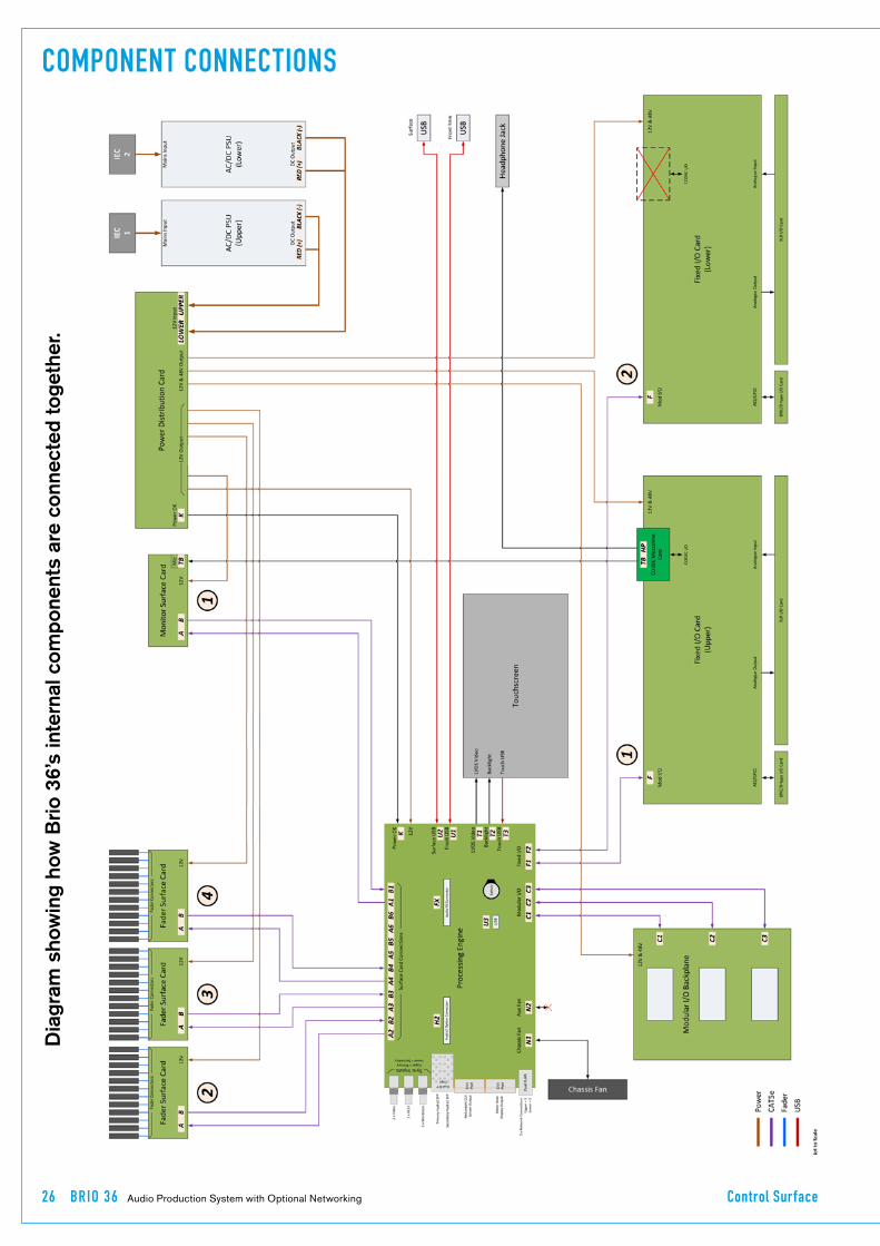
Dia
gram
sho
win
g ho
w B
rio 3
6’s
inte
rnal
com
pone
nts
are
conn
ecte
d to
geth
er.
COMPONENT CONNECTIONS

CA LREC Putting Sound in the Picture 27
SURFACE LAYOUT
The BRIO 36 surface is built as 2 panels top and bottom.
It is made up from 3 x 12 fader sections, 2 across the bottom and one top left and one Access Panel placed top right which contains the Access display area complete with touchscreen TFT, 8 context based rotary controls, 12 Global user switches G1 to G12, A/B layer selection, Link Switch, Monitor Controls, PFL level, Reset switch and USB port used for data transfers. In addition there is a USB port for a keyboard/mouse combination and a Stereo 1/4” Headphone socket in the front.
BRIO 36 SURFACE AREAS
12 Fader Section
12 Fader Section Touchscreen Panel
12 Fader Section
Access, User andMonitor Controls, Reset & USB Port
Fader ControlsAFL, PFL & Cut
Fader Displays Rotary Controls Access Buttons& User Buttons

28 BR IO 36 Audio Production System with Optional Networking Control Surface
The built-in talkback microphone and the headphone socket, are patched to dedicated internal ports in (SLOT M) and DO�NOT�appear as external audio port connections on the rear panel.
The�built-in�talkback�mic�appears�as�a�source�in�I/O�patching�lists�as�port�M-01.�By�default,�this�is�connected�to�the�console’s�DSP�talkback�input.�Other�internal�or�external�inputs�can�be�connected�instead�to�the�DSP�talkback�input�if�a�different�microphone,�or�output�from�a�3rd�party�comms�system�is�preferred.��
HEADPHONE AND TALKBACK MICROPHONE
The�output�from�the�built-in�microphone�can�also�be�patched�to�other�outputs/console�inputs�as�well�as�the�talkback�if�required�(e.g.�to�feed�into�a�comms�system).
The�headphone�socket�appears�as�destinations�M-01�(Left)�and�M-02�(right)�in�the�I/O�patching�lists.��By�Default,�this�is�connected�from�the�Studio�Monitor�2�output,�but�can�be�fed�from�other�monitor�or�path�outputs,�or�from�inputs�if�required.�
Headphone�and�Talkback�Microphone�ConnectionsThe�Brio�36�built-in�talkback�microphone�is�situated�above�the�User�G1�button�in�the�Monitor�panel�area,�directly�under�the�Touch�Display.��The�headphone�socket�is�fixed�to�the�front�right�of�the�surface,�just�under�the�arm�rest.
BRIO 36 LOCATIONS OF HEADPHONE SOCKET AND TALKBACK MICROPHONE.

CA LREC Putting Sound in the Picture 29
POWER SUPPLY UNITS
Brio 36’s power supply unit (PSU) contains two power supply units which are supplied with AC power by two independent male IEC inlets. These dual power supplies provide full power redundancy, a feature of all Calrec products.
Although�Brio�36�will�run�with�only�one�PSU�powered�on,�it�is�recommended�that,�to�ensure�power�redundancy,�these�two�IEC�inlets�should�be�supplied�by�separate�AC�power�supplies.�
A�PSU�failure�or�a�loss�of�AC�power�input�will�generate�a�system�status�error�message�(See�the�Brio�36�User�manual�for�more�information�on�system�status�monitoring).�
The two PSU’s employ load sharing, if one PSU fails, the other will automatically take over the full load with no loss of audio or operation.
Disconnecting�the�PSUsBrio�36�does�not�contain�a�separate�Mains�power�switch.��To�safely�disconnect�the�mains�power�both�IEC�connectors�need�to�be�removed�from�the�rear�of�the�console,�as�shown�below.
Power�DistributionThe�power�supply�module�connects�to�an�internal�Power�Distribution�Board�providing�12�V�DC�&�48�V�DC�power�to�Brio�36’s�internal�components.��
The�Touch�Display�is�powered�via�its�connections�to�the�Processing�Engine�card.��Note,�the�Touch�Display�also�has�a�backlight�which�is�powered�via�a�separate�12�V�DC�connection�from�the�Processing�Engine�card.
BRIO 36 REAR VIEW SHOWING PSU MAINS CONNECTION AND RATINGS LABEL

30 BRIO 36 Audio Production System with Optional Networking

calrec.com Putting Sound in the Picture
BRIO 36CONNECTION INFORMATION

32 BR IO 36 Audio Production System with Optional Networking Connection Information
SYNCHRONISATION
The Brio 36 has 6 BNC connections for external synchronisation:-2 x Wordclock inputs, 2 x AES inputs and 2 x Video inputs. If no external sync is connected and selected, the console will free-run on its own internal clock generated by the active router card.
General�rules�of�good�practise�require�that�all�equipment�connected�to�the�audio�console’s�digital�inputs�and�outputs�are�locked�to�the�same�referenced�sync�source�as�the�console�to�ensure�clean�audio.�In�systems�with�multiple�Calrec�processing�cores�connected�together,�it�is�of�paramount�importance�that�all�connected�processing�cores�are�locked�to�the�same�referenced�sync�source.�
If�one�or�more�cores�receives�a�sync�signal�that�is�not�locked�from�the�same�clock�reference�as�other�cores,�interruptions�to�both�audio�and�data�carried�by�routers�can�be�caused.��This�can�lead�to�false�error�warnings�and�I/O�boxes�going�offline.�Therefore,�it�is�essential�to�consider�a�robust�sync�distribution�design�for�a�facility�and�to�ensure�all�points�in�the�chain�are�correctly�configured�to�lock�to�the�appropriate�input�and�no�elements,�such�as�sync�regenerators,�are�free-running�or�making�changes�to�the�reference�source.
It�is�also�recommended�that�backup�sync�sources�and�paths�are�considered�to�maintain�full�functionality�in�the�event�of�the�loss�of�any�part�of�the�facility’s�sync�distribution�system.
External�sync�sources�can�be�fed�to�the�BNC�connectors�on�the�rear�of�the�console�as�shown�above�right.��Two�inputs�are�available�for�video�formats,�as�well�as�two�inputs�for�TTL�Wordclock�and�two�inputs�for�AES3�digital�audio�reference.
See�External�sources�table�right�and�the�Brio�36�User�manual�for�information�on�how�to�set�up�synchronisation�priority.���
The�console�will�always�attempt�to�boot�to�the�highest�priority�sync�selected,�and�move�down�the�priority�list�until�it�finds�a�valid�sync.
SYNC INPUTS
EXTERNAL SOURCES TABLE
If�a�valid�sync�later�fails,�it�will�move�down�the�list.�If�no�valid�sync�present,�will�always�default�to�internal�as�this�is�fixed�as�the�last�source�in�the�list.��The�priority�will�never�automatically�move�back�up�the�list�even�if�a�higher�priority�sync�becomes�available.��Press�the�reset�to�first�button�to�move�back�up�to�the�top�of�the�list.��
It�is�important�that�the�required�sync�source�is�available�before�the�console�boots�up�otherwise�it�won’t�be�locked�to�the�correct�sync,�if�this�occurs�press�the�‘Reset�to�first’�button�after�the�sync�generator�is�running.
Synchronisation�at�different�sample�rates:Hydra2�runs�at�48kHz�irrespective�of�whether�the�consoles�and�I/O�boxes�are�running�at�96kHz�or�not.���It�simply�uses�2�samples�per�96kHz�signal.��The�system�will�still�require�a�48kHz�sync�if�using�its�AES3�or�Wordclock�inputs�even,�if�all�consoles�and�I/O�are�operating�at�96kHz.

CA LREC Putting Sound in the Picture 33
AUDIO I/O CONNECTIONS
There are a number of ways to get Audio in and out of a Brio 36 system. There are built in Analogue and Digital Inputs, 3 double width modular I/O card slots which can use any of the cards from the Modular I/O box range and it can also connect to Hydra 2 networks via the optional H2 module.
The�optional�Hydra�2�Module�allows�further�I/O�to�be�connected�in�the�form�of�any�Hydra�2�I/O�box,�fixed�format�or�modular.��Multiple�I/O�boxes�can�be�connected�via�H2Hubs,�and�from�V1.1,�Brio�consoles�can�connect�to�router�ports�on�Apollo/Artemis/Summa/Router�cores�to�share�audio�over�a�wider,�multiconsole�Hydra2�network.
Built-In�Audio�InterfacesThe�image�below�shows�the�Audio�interfaces�available�to�he�user�without�the�optional�Hydra�2�interface�module.There�are:-8�x�Digital�AES�I/Ps,�with�SRC,8�x�Digital�AES�O/Ps,24�x�Analogue�Mic/Line�I/Ps,�16�x�Analogue�Line�O/Ps�3�double�width�Mod�I/O�card�slots.
Note�that�the�image�also�shows�the�built-in�GPIO�connectors,�there�are�4�x�9-pin�D-Type�connectors�each�of�which�carry�either�4�GPI�or�4�GPO�circuits,�this�gives�Brio�36�a�total�of�8�x�GPIs�and�8�GPOs.
Optional�Hydra�2�Audio�FormatsHydra2�I/O�units�come�in�a�variety�of�formats�and�connector�types,�including�MADI�and�SDI�embedders/de-embedders,�AES�digital�and�mic/line�analogue�formats,�all�with�a�variety�of�connector�types.��Please�refer�to�the�Hydra2�installation�manual�for�full�details�on�I/O.
PowerAll�External�Hydra2�I/O�units�are�fitted�with�dual�power�supplies�and�IEC�AC�power�input�connectors�operating�from�100-240�VAC.��Both�power�inputs�should�be�fed,�preferably�from�two�separate�AC�sources,�to�provide�full�redundancy.���
IEC�‘Y’�cords�can�be�supplied�to�allow�both�inputs�to�be�fed�from�a�single�cable�source,�in�the�event�that�only�one�supply�is�available,�to�ensure�both�PSUs�can�always�be�fed.
ID�configurationEach�I/O�box�in�a�system�needs�to�be�given�a�unique�hydra�ID�(HID),�see����“Hydra�I/O�Box�IDs”�on�page�14����������for�further�information.
Modular�I/O�card�slotsPlease�note�that�changing�the�card�type�fitted�in�a�modular�I/O�card�slot�requires�the�user�to�remove�it�from�the�required�I/O�List�however�if�on�a�network�it�also�needs�to�be�removed�from�the�network�
configuration�using�H20�and�resetting�the�master�router�is�required�to�add�the�replacement�cards�in�H2O.
For�guidance�in�the�use�of�H2O�refer�to�����the�H2O�User�Guide�which�can�be�found�on�the�Calrec�website
If�the�order�that�cards�are�fitted�in�a�modular�frame�is�important�in�your�installation,�please�discuss�this�with�your�supplier�prior�to�delivery.��If�for�any�reason�the�card�order�needs�to�be�changed�post�delivery,�please�contact�our�Customer�Support�team�or�your�local�distributor�for�guidance.��Cards�of�the�same�type�can�be�interchanged�with�no�configuration�change�required.��Additional�cards�can�be�fitted�in�previously�empty�slots�without�further�configuration.�
Hydra2�connectionLike�the�Hydra2�ports�on�the�router�card,�Hydra2�connections�on�the�back�of�the�Brio�36�and�I/O�boxes�are�SFPs�and�therefore�the�connection�type�required�(copper/single�mode�fibre/multimode�fibre)�needs�to�be�specified�during�the�ordering�process.�
Note, any fixed RJ45s on the rear of External Hydra2 I/O boxes are not functional, if copper connections are required, copper SFPs should be specified.
BUILT-IN AUDIO CONNECTIONS

34 BR IO 36 Audio Production System with Optional Networking Connection Information
MODULAR HYDRA2 I/O, CONTROLLER CARD FRONT INTERFACE
Connect�from�Primary�Hydra�2�SFP�on�Brio�36
Connect�from�Secondary�Hydra�2�SFP�on�Brio�36
Connection�from�Primary�����Hydra�2�SFP�on�Brio�36
Connection�from�Secondary�Hydra�2�SFP�on�Brio�36
No�Connection
FIXED FORMAT I/O REAR CONNECTIONS
CA LREC Putting Sound in the Picture 35
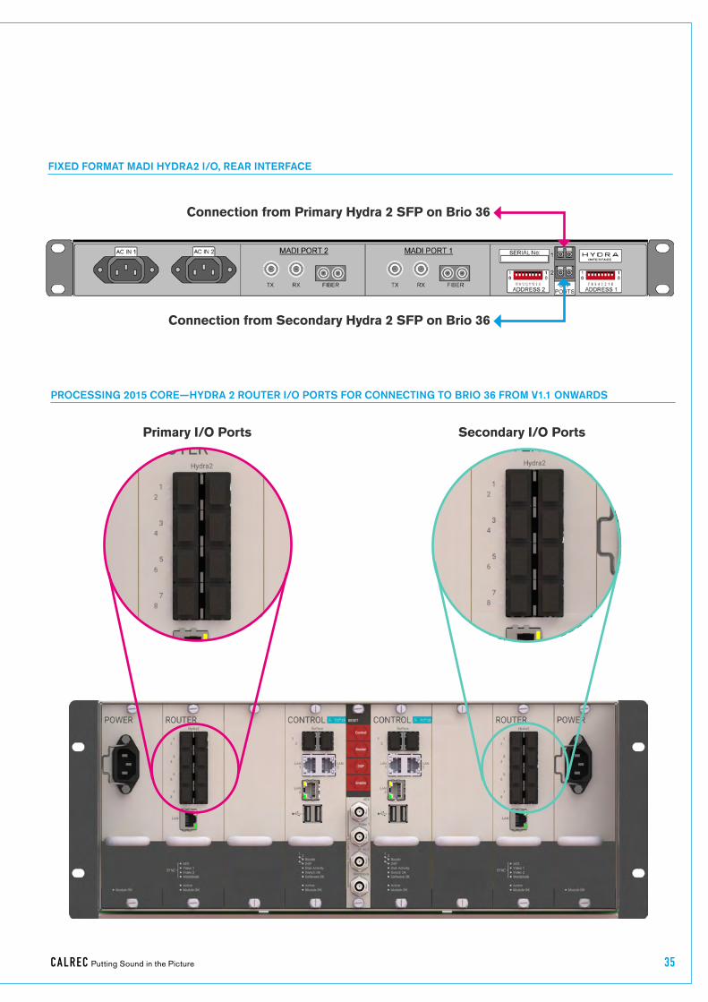
FIXED FORMAT MADI HYDRA2 I/O, REAR INTERFACE
Connection�from�Primary�Hydra�2�SFP�on�Brio�36
Connection�from�Secondary�Hydra�2�SFP�on�Brio�36
PROCESSING 2015 CORE—HYDRA 2 ROUTER I/O PORTS FOR CONNECTING TO BRIO 36 FROM V1.1 ONWARDS
Primary�I/O�Ports Secondary�I/O�Ports

36 BR IO 36 Audio Production System with Optional Networking Connection Information
SMALL FORM-FACTOR PLUGGABLE (SFP) OVERVIEW
Connections between the Brio 36 control surface (which includes the processing core) and all Hydra2 network connections, connections between I/O boxes and routers and router-to-router connections between cores, are all made via SFP modules.
SFPs�can�be�provided�for�RJ45�copper�connections,�as�well�as�singlemode�or�multimode�fibre�on�LC�connectors.��This�allows�for�each�port’s�connection�type�to�be�chosen�to�suit�cable-run�distances�and�the�existing�infrastructure.��SFPs�can�be�changed�easily�on�a�port�by�port�basis,�as�and�when�required.
If�Calrec�are�supplying�SFPs�for�your�installation,�the�correct�quantity�of�SFPs�are�supplied�pre-fitted.��The�type�of�each�connection—copper,�singlemode�fibre�or�multimode�fibre—should�be�specified�at�the�time�of�order�to�ensure�the�correct�SFP�types�are�supplied.��Additional�SFP�modules�can�be�ordered�if�required.��If�a�system�is�to�be�connected�to�an�existing�Hydra2�network,�please�discuss�this�with�your�Calrec�project�leader,�sales�person�or�local�distributor�to�ensure�that�SFPs�are�provided�and�ports�provisioned�for�the�additional�router�to�router�connections.
SFP�slot�orientationSFP�modules�plug�into�rear�panel�slots�on�Brio�36�&�fixed�format�I/O�boxes,�and�into�front�panel�slots�on�router�and�modular�I/O�controller�cards.��The�modules�can�be�fitted�or�removed�whilst�the�system�is�powered�up�and�without�removing�or�opening�any�card�or�box�casings.�
Note�the�orientation�of�the�SFP�modules�as�shown�in�the�illustrations�on�this�page.
BRIO 36 SFPS
SFP�Modules�fitted�in�Brio�36�are�orientated�so�that�the�RJ45�connector�catch�and�the�Fibre�LC�connect�key�are��at�the�top.
Likewise�for�fixed�format�I/O�boxes,�the�primary�SFP�module�is�the�opposite�way�around�to�the�secondary�SFP�module.��The�modules�are�orientated�so�that�the�release�catch�for�the�RJ45/LC�connector�plugs,�once�inserted,�are�on�the�outside�edge.�
For�modular�I/O�box�controller�cards,�both�SFP�slots�are�orientated�so�that�the�release�catch�on�the�cable/fibre�connector�is�on�the�right-hand�side.
Modules�fitted�in�Router�cards�even�numbered�router�ports�(left�hand�column)�are�fitted�the�opposite�way�around�to�those�in�the�odd�numbered�router�ports�(right�hand�column).��
SFP MODULES
1
3
5
7
2
4
6
8
16 15
SFPPORTS
2
INTERFACE
67 5 4 3 2 1 0ADDRESS 1
100
1
RYH D A1
ROUTER CARD SFPS
FIXED FORMAT I/O BOX SFPS
•� Router�card�shown�with�copper�SFPs�fitted�in�ports�1-4,�singlemode�fibre�(button�release)�in�ports�5-8.
•� I/O�box�shown�with�singlemode�fibre�SFPs�(button�release)�fitted.•� Both�SFP�types�above�have�
a�handle�latching�mechanism,�shown�in�the�locked�position.��The�unit�on�the�left�is�a�singlemode�duplex�LC�fibre�module.��The�unit�on�the�right�is�a�copper�RJ45�module�type�which�must�support�LOS�detection.
STATUSH2 I/F
RESET
WCLK OUT
1
2
HB1
SOFT
CTRL2
AUD2
PSU2
H_ACT
HB2
CTRL1
AUD1
PSU1
FAN1FAN2
FAN 12V
MODULAR I/O BOX SFPS
•� Modular�I/O�controller�card�SFPs�are�both�orientated�the�same�way�around�(Button�release�singlemode�fibre�SFPs�shown).
•� Brio�36�Hydra�2�interface�on�rear�shown�with�copper�SFPs�fitted.

CA LREC Putting Sound in the Picture 37
12
12
SFPS WITH HANDLES - LATCHED
•� Both�SFPs�shown�are�locked�in�place��-�Latch�/�extraction�handles�in�outer�position�(or�‘down’�position�for�fibre).
SFPS WITH HANDLES - UNLATCHED
•� Both�SFPs�free�to�remove�-�Latch�/�extraction�handles�in�inner�(or�‘Lifted’�for�fibre)�position.
AUTO-LATCHING SFP
•� Depress�the�release�button�to�remove.
SFP�latching�and�extractionCalrec�source�SFP�modules�from�various�manufacturers.��All�types�used�conform�to�the�same�specification,�however�the�latching�mechanisms�can�vary�slightly.
The�standard�copper�SFP�and�some�fibre�SFPs,�as�shown�in�the�photograph�on�the�previous�page,�have�latch/extraction�handles.��On�insertion,�the�handles�should�be�set�against�the�outer�edge�(the�same�side�as�the�release�catch�on�the�RJ45�/�LC�connector�plug�that�fits�into�the�SFP)�to�lock�it�into�place�and�prevent�accidental�removal�if�cables�are�pulled.�
To�remove�this�style�of�SFP,�remove�the�cable/fibre�and�slide�the�handle�(copper)�or�lift�the�handle�out�(fibre)�to�the�inside�edge,�as�shown�in�the�diagram�to�the�right.��The�module�can�then�be�removed�by�pulling�on�the�handle.
Other�SFPs�automatically�latch�into�place�when�they�are�inserted�fully�and�they�have�a�release�button�on�their�inside�edge.�The�fibre�SFPs�shown�in�the�orientation�diagrams�and�on�this�page�are�of�this�type�
and�have�blue�release�buttons.��To�remove,�depress�the�button�using�a�small�flat�blade,�screwdriver�or�similar�tool.��The�SFP�module�will�then�be�free�to�be�removed.
SFP�slot�coversDust�covers�should�be�fitted�to�all�SFP�slots�that�do�not�have�SFP�modules�fitted�in�them�in�order�to�maintain�connection�reliability.
Loose�SFP�storageSFP�modules�are�small,�yet�reasonably�expensive�devices.��When�removing�or�changing�SFPs,�take�care�to�keep�track�of�them�and�store�loose�modules�in�a�clean,�dry,�and�anti-static�environment.��Fibre�SFPs�should�always�have�a�dust�cover�fitted�into�their�optical�transceiver�end�when�no�fibre�is�connected�to�them.
Calrec will not be liable for lost or missing SFP modules, or damage due to poor storage. SFP�design�varies�depending�on�the�manufacturer,�please�ensure�that�SFPs�are�correctly�latched�in�place�after�fitting�them.��In�the�event�that�a�connection�is�not�automatically�established�after�hot-plugging�an�SFP,�please�reset�the�unit�the�SFP�is�plugged�in�to.

38 BR IO 36 Audio Production System with Optional Networking Connection Information
COPPER SFP CONNECTIVITY
Hydra2 network connections can be made via copper SFP modules. Copper connections require shielded F/UTP Category 5e or Category 6 cables with shielded RJ45 mating connectors. Surface to Core connections can only be made using optical/fibre SFP modules.
It is important to note that Copper SFPs must support LOS (Loss of Signal detection) - this is not standard for copper SFPs, but are commonly available, Calrec supplied Copper SFPs do support LOS.
Calrec�do�not�supply�copper�cables�as�it�is�often�preferable�to�terminate�them�after�they�have�been�run�through�cable�ducting�to�avoid�damaging�the�terminations,�and�to�be�able�to�cut�them�to�the�precise�length�required.
Shielded�cables�and�connectorsShielded�cabling�and�connectors�are�required�in�order�to�meet�EMC�(Electro-magnetic�compatibility)�standards�to�comply�with�the�radiated�emission�limits�set�in�the�EN55022�standard,�as�well�as�to�guarantee�performance�in�electrically�noisy�environments.
F/UTP�Cat5e/Cat6�cable�has�an�overall�foil�shield�around�the�conductor�cores.�Shielded�RJ45�connector�plugs�have�a�metallic�shield�around�them�which�should�be�clamped/bonded�to�the�shield�within�the�cable.��The�connector�shield�connects�with�the�chassis�of�the�RJ45�socket�that�
it�is�plugged�into,�providing�an�earth�to�the�cable�shield.
The�method�of�attaching�the�connector�shield�to�the�cable�shield�can�vary.��Please�refer�to�the�connector�manufacturer’s�information�for�further�guidance.
Maximum�cable�lengthThe�maximum�length�of�Cat5e/Cat6�cables�is�90�m/295�ft.��This�is�the�absolute�maximum�and�needs�to�include�any�patch�points�and�cables�that�may�be�in�the�path.��Hydra2�cable�runs�can�NOT�be�extended�using�Ethernet�switches,�hubs�or�repeaters.��If�a�run�between�Hydra2�hardware�exceeds�the�maximum�recommended�distance�for�copper�cabling,�fibre�and�optical�SFPs�should�be�used�instead.
Cable�routing�considerationsThe�layout�and�twist�rate�of�the�data�cores�within�Cat5e/Cat6�cables�are�integral�to�their�performance�at�high�speed�over�distance.��Poor�practise�during�installation�can�seriously�impact�upon�this.��The�following�are�general�rules�of�good�practise�but�please�refer�to�the�cable�manufacturer’s�information�for�comprehensive�installation�rules:
•� When�running�Cat5e/Cat6�network�cabling,�it�is�important�to�avoid�kinking�the�cable.��Kinks�can�seriously�impair�performance.��Cable�manufacturers�advise�that�kinked�cables�should�be�discarded�and�replaced�as�the�damage�caused�cannot�be�addressed�simply�by�straightening�them�out.
•� Cables�should�not�be�bent�in�tight�angles,�this�too�can�seriously�impair�performance.��Please�refer�to�the�cable�manufacturer’s�specification�on�minimum�bend�radii.
•� Excessive�pulling�force�when�routing�cables�can�deform�the�twist�rate�of�the�cable�cores,�causing�irreparable�damage.��Cable�manufacturers�specify�a�maximum�pulling�tension.
•� Cable�ties�should�not�be�over-tightened�as�this�deforms�the�internal�structure�of�the�cable.��Cable�ties�should�be�tight�
enough�to�support�the�cable�weight�but�not�so�tight�as�to�cause�any�visible�deformation�to�the�cable’s�outer�jacket.�Large,�heavy�bundles�of�cables�can�be�difficult�to�support�using�cable�ties�without�causing�damage.�‘Velcro’�style�hook-and-loop�cable�straps�can�be�a�good�alternative�to�plastic�cable�ties.
•� Whilst�neatly�bundled�parallel�cable�runs�are�tidy�and�aesthetically�pleasing,�they�can�increase�cross-talk,�which�can�impact�on�performance.��Avoid�neat�bundling�of�network�cables�over�any�kind�of�distance—the�majority�of�a�cables�length�is�normally�unseen,�running�under�floor�or�through�ducting�where�they�should�be�loosely�laid�rather�than�neatly�bundled.
Termination�-�strain�reliefPoor�termination�and�lack�of�strain�relief�is�one�of�the�most�common�causes�of�high�speed�network�cable�problems.���������������To�properly�relieve�strain�on�the�data�cores,�the�outer�jacket�of�the�cable�should�be�inserted�into�the�RJ45�housing�and�held�in�place�once�crimped�at�the�strain-relief�point,�as�shown�in�the�diagram�above.��This�also�maintains�the�integrity�of�the�twist�rate�and�shield�into�the�termination,�ensuring�the�full�length�of�the�cable�conforms�to�its�specification.��Slide�on�outer�boots�offer�additional�strain-relief�protection�but�are�not�sufficient�on�their�own.�
SHIELDED RJ45 CONNECTOR
Conductive�connector�mating�screen�clamped�/�bonded�to�cable�shield
Crimp�points
Cable�outer�jacket
Strain�relief
STRAIN RELIEVED RJ45 TERMINATION
•� Note,�this�is�a�simplified�diagram�that�does�not�include�the�shield.
CA LREC Putting Sound in the Picture 39
In�order�to�be�able�to�crimp�the�cable�jacket�inside�the�RJ45�and�land�the�data�cores�on�the�terminals,�the�amount�that�the�jacket�is�stripped�back�in�relation�to�the�cores�needs�to�be�accurate.��Cables�with�exposed�data�cores�should�not�be�used�as�they�will�be�unreliable.
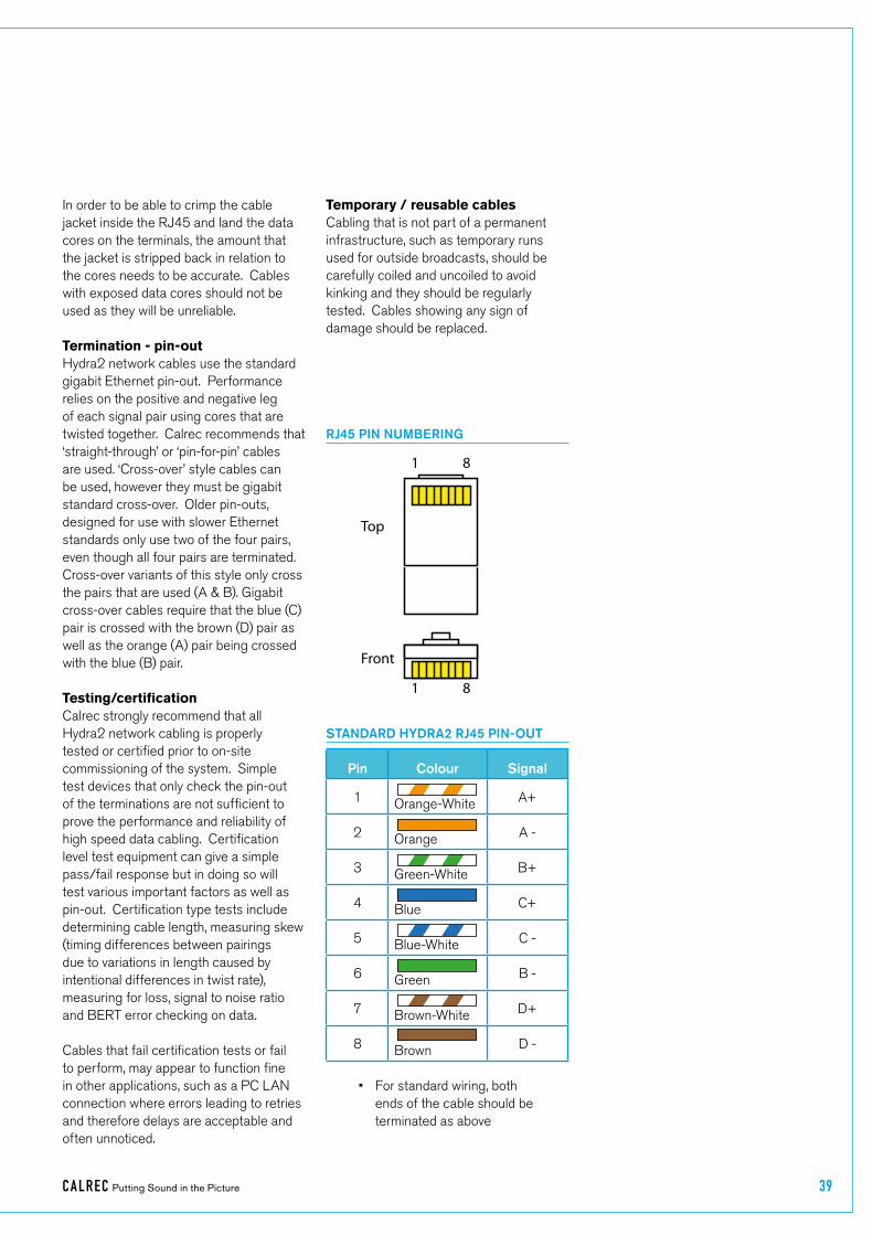
Termination�-�pin-outHydra2�network�cables�use�the�standard�gigabit�Ethernet�pin-out.��Performance�relies�on�the�positive�and�negative�leg�of�each�signal�pair�using�cores�that�are�twisted�together.��Calrec�recommends�that�‘straight-through’�or�‘pin-for-pin’�cables�are�used.�‘Cross-over’�style�cables�can�be�used,�however�they�must�be�gigabit�standard�cross-over.��Older�pin-outs,�designed�for�use�with�slower�Ethernet�standards�only�use�two�of�the�four�pairs,�even�though�all�four�pairs�are�terminated.�Cross-over�variants�of�this�style�only�cross�the�pairs�that�are�used�(A�&�B).�Gigabit�cross-over�cables�require�that�the�blue�(C)�pair�is�crossed�with�the�brown�(D)�pair�as�well�as�the�orange�(A)�pair�being�crossed�with�the�blue�(B)�pair.
Testing/certificationCalrec�strongly�recommend�that�all�Hydra2�network�cabling�is�properly�tested�or�certified�prior�to�on-site�commissioning�of�the�system.��Simple�test�devices�that�only�check�the�pin-out�of�the�terminations�are�not�sufficient�to�prove�the�performance�and�reliability�of�high�speed�data�cabling.��Certification�level�test�equipment�can�give�a�simple�pass/fail�response�but�in�doing�so�will�test�various�important�factors�as�well�as�pin-out.��Certification�type�tests�include�determining�cable�length,�measuring�skew�(timing�differences�between�pairings�due�to�variations�in�length�caused�by�intentional�differences�in�twist�rate),�measuring�for�loss,�signal�to�noise�ratio�and�BERT�error�checking�on�data.
Cables�that�fail�certification�tests�or�fail�to�perform,�may�appear�to�function�fine�in�other�applications,�such�as�a�PC�LAN�connection�where�errors�leading�to�retries�and�therefore�delays�are�acceptable�and�often�unnoticed.�
Temporary�/�reusable�cablesCabling�that�is�not�part�of�a�permanent�infrastructure,�such�as�temporary�runs�used�for�outside�broadcasts,�should�be�carefully�coiled�and�uncoiled�to�avoid�kinking�and�they�should�be�regularly�tested.��Cables�showing�any�sign�of�damage�should�be�replaced.
STANDARD HYDRA2 RJ45 PIN-OUT
Pin Colour Signal
1 Orange-White A+
2 Orange A�-
3 Green-White B+
4 Blue C+
5 Blue-White C�-
6 Green B�-
7 Brown-White D+
8 Brown D�-
1 8
Top
Front
1 8
RJ45 PIN NUMBERING
•� For�standard�wiring,�both�ends�of�the�cable�should�be�terminated�as�above

40 BR IO 36 Audio Production System with Optional Networking Connection Information
FIBRE SFP CONNECTIVITY
Optical SFP modules for fibre connectivity can be used for console to processing core, router to router, and router to I/O connections.
Fibre�connectivity�is�required�when�the�cable�run�between�units�exceeds�the�90�m�maximum�permissible�length�for�Cat5e/Cat6�copper�cabling.��Fibre�can�also�be�used�for�shorter�runs�if�it�is�simply�the�preferred�medium.
Note,�this�section�only�concerns�fibre�connections�made�via�SFPs.��Like�all�I/O�boxes,�MADI�units�have�pluggable�SFPs�for�their�Hydra2�connections�to�routers,�but�they�also�have�fibre�connectors�that�pass�the�actual�MADI�audio�format�in�and�out�of�the�system.��The�MADI�I/O�format�fibre�connectors�are�of�a�fixed�type�which�has�no�relation�to�SFP�choice.��Various��MADI�I/O�boxes�are�available�to�provide�different�types�of�MADI�fibre�interface.�Please�refer�to�the�Hydra2�installation�manual�for�more�details�on�MADI�I/O�options.
Singlemode�vs�MultimodeThe�core�within�multimode�fibre�is�relatively�thick�when�compared�to�singlemode.��Light�travels�through�multimode�fibre�at�multiple�angles,�‘bouncing’�off�the�sides�of�the�core�as�it�travels,�taking�multiple�paths�or�‘modes’�of�varying�length�from�one�end�to�the�other,�resulting�in�pulses�being�lengthened�as�they�travel.��Singlemode�fibre�has�a�very�fine�core�and�light�travels�in�a�single,�direct�path�from�one�end�to�the�other�without�
affecting�pulse�length.��The�result�is�that�singlemode�fibre�has�a�higher�bandwidth�capacity�and,�importantly,�low�signal�loss�allowing�much�greater�distances�to�be�achieved.��Light�can�be�transmitted�into�multimode�fibre�using�LEDs�or�low�powered�lasers�whilst�singlemode�requires�a�higher�powered�laser.
Calrec�recommend�the�use�of�singlemode�fibre�whenever�possible�in�order�to�maximise�the�flexibility�in�the�location�of�hardware�and�maintain�uniformity�across�the�system�by�using�a�single�type.��If�a�multimode�infrastructure�is�in�place,�fibre�length,�the�number�of�inter-connects�and�equipment�location�become�more�important.
SFP�modules�are�available�for�both�singlemode�and�multimode�fibre�types.�It�is�important�to�select�the�correct�SFP�for�the�type�of�fibre�being�used�in�the�installation.��If�using�a�mixture�of�singlemode�and�multimode�fibre,�it�is�important�to�ensure�the�correct�SFPs�are�matched�to�the�correct�fibre�type.
IdentificationThe�release�button/handles�of�fibre�SFPs�are�colour�coded�-�Blue�for�singlemode,�Black�for�multimode.�Blue�LC�connectors,�as�shown�here,�should�be�used�to�terminate�singlemode�fibre�and�beige�coloured�connectors�for�multimode.
Duplex�Connectors�/�TerminationsStandard�Calrec�fibre�SFPs,�both�multimode�and�singlemode,�use�duplex�
LC�connectors.��The�duplex�termination�requires�two�fibres�per�connection,�one�is�a�send�path,�the�other�is�a�receive�path.�When�terminating�the�fibre,�the�send�from�one�end�should�connect�to�the�receive�of�the�other�and�therefore�they�‘cross-over’,�terminated�A�to�B�and�B�to�A.
Single�Strand,�Bi-Directional�SFPsTo�reduce�the�amount�of�fibre,�Calrec�can�supply�singlemode�SFPs�that�send�and�receive�over�a�single,�or�simplex�LC�connector.��In�order�to�be�able�to�pass�data�in�both�directions�over�a�single�strand,�the�light�travelling�in�one�direction�needs�to�be�of�a�different�wavelength�to�the�light�travelling�in�the�other�direction.�Therefore,�Bi-Directional�SFPs�come�as�either�type�A�or�type�B��(as�indicated�by�an�A�or�B�at�the�end�of�the�model�number)�and�they�need�to�be�paired�up;�a�fibre�should�connect�between�a�type�A�and�a�type�B,�and�not�between�two�Bi-Directional�SFPs�of�the�same�type/wavelength.��The�units�are�colour�coded�to�aid�identification�between�A�types�&�B�types.
SFP�Fibre�SpecificationsSpecifications�are�shown�in�the�table�to�the�right.��The�maximum�distances�shown�here�assume�a�single�point-to-point�connection�with�no�intermediary�interconnections.��Losses�should�be�measured�across�the�total�signal�path�including�interconnects�-�between�points�of�SFP�transceiver�connection.��Losses�need�to�be�less�than�the�optical�power�budget�of�the�SFP�transceivers�being�used.
DUPLEX LC FIBRES CORRECTLY TERMINATED A TO B & B TO A
BI-DIRECTIONAL LC FIBRE CORRECTLY CONNECTED, TYPE A TO TYPE B
A
AB
B
A B

CA LREC Putting Sound in the Picture 41
SFP Type Connector Power Budget Fibre Type Max Distance
SX Multimode LC�Duplex 7.5�dB
62.5/125�µm 275�m
50/125�µm 550�m
LX Singlemode LC�Duplex 8�dB 8/125�µm 10�km
LX Singlemode bi-dir LC�Simplex 11.5�dB 9/125�µm 10�km
LH Singlemode LC�Duplex 23�dB 8/125�µm 70�km
SFP/FIBRE SPECIFICATIONS

42 BR IO 36 Audio Production System with Optional Networking Connection Information
FIBRE - GENERAL RULES
Testing�/�CertificationCalrec�strongly�recommends�that�all�fibres�are�properly�tested�or�certified�prior�to�on-site�commissioning�of�the�system.�A�certain�amount�of�signal�loss�occurs�over�the�length�of�a�fibre�path.��If�the�total�loss�of�a�path�exceeds�the�optical�power�budget�of�the�SFPs�in�use,�the�system�will�be�unreliable.
Areas�of�LossSignal�loss�occurs�in�various�areas.��Splice�loss�occurs�in�terminations—at�the�point�where�the�fibre�meets�the�connector.�Typically�splice�loss�should�be�<0.3�dB�per�termination.�Poor�termination�results�in�higher�loss.�
Connector�loss�occurs�at�the�point�where�the�connector�meets�the�SFP/optical�transceiver,�or�other�connectors,�such�as�extension�interconnects�or�patch-points.��Connector�loss�should�typically�be�<0.5�dB�per�interconnect.��Dust�or�other�contamination�between�interconnects�or�scratches�on�the�end�surface�contact�point�of�the�fibre�will�substantially�increase�the�amount�of�loss.��As�such,�dust�covers�should�always�be�fitted�to�optical�SFPs�when�no�fibre�is�connected,�and�to�fibre�connectors�that�are�not�landed.�
As�well�as�splice�and�connector�loss,�the�fibre�itself�has�inherent�loss�over�distance,�typically�fibre�loss�will�vary�from�3.5�dB�per�km�for�multimode�down�to�0.4�dB�per�km�for�singlemode.��Poor�installation�practise�and�lack�of�care�can�damage�the�fibre�and�result�in�substantially�increased�losses.�
Fibre�Handling�PractiseIt�is�important�to�follow�the�fibre�manufacturer’s�guidelines�when�handling�fibre�and�installing�fibre�runs.��Some�of�the�main�points�of�concern�are:
•� Minimum�bend�radii—fibre�should�not�be�bent�through�too�tight�an�angle.�Tight�angles�can�cause�significant�losses�and�permanent�damage�to�the�fibre.��Fibres�may�pass�initial�installation�testing�but�can�fail�at�a�later�date�due�to�stresses�on�the�core�of�the�fibre�caused�by�tight�bends.
•� Twists,�snags�and�kinks—Twists�in�fibre�runs�add�stresses�to�the�core�which�can�cause�damage�over�time.��Avoid�snagging�on�other�cables�or�conduit�which�will�cause�excessive�tensions�when�pulling�and�can�cause�kinks�and�excessive�bends�in�the�fibre.��When�routing�through�angled�conduit,�provide�enough�clearance�around�corners�to�avoid�the�fibres�being�pulled�sharply�around�the�inside�of�the�angle.
•� Pulling—observe�the�manufacturers�maximum�pulling�tension�specification.�Use�pulling�tools�and�lubrication�where�appropriate.��Never�pull�on�the�connector.
•� Strain�relief—fibres�should�have�adequate�strain�relief�to�prevent�tension�on�terminations,�however�use�of�plastic�cable�ties�can�crush�the�internal�construction�of�the�cable.��Hook-and-loop�‘Velcro’�straps�are�harder�to�over-tighten�and�offer�more�gentle�support�and�a�greater�surface�area�to�dissipate�the�pressure.
•� Crushing—never�place�heavy�items�on�top�of�unprotected�fibre.
Ruggedised�FibreTemporary/re-usable�fibre�runs,�or�runs�unprotected�by�conduit�and�likely�to�be�exposed�to�the�elements,�snagging�or�to�being�stood�on,�should�always�be�of�a�ruggedised/armoured�type�to�protect�the�internal�construction�of�the�core.
Cleaning�and�Preventative�MaintenanceContamination�of�transceiver�and�fibre�mating�contact�points�causes�signal�loss�and�can�cause�permanent�damage�by�scratching.
Dust�covers�should�be�fitted�to�all�fibre�connectors�and�SFP�optical�transceivers�when�they�are�not�mated.�It�is�also�important�to�ensure�that�dust�covers�themselves�are�kept�clean.
When�handling�fibres�without�dust�covers,�do�not�allow�the�ends�to�come�into�contact�with�any�surface.
Specialist�materials�should�be�used�for�the�cleaning�of�mating�contact�points�to�avoid�further�contamination�or�scratching.�The�following�items�are�low�cost�and�readily�available�from�camera�shops�and�laboratory�suppliers:
•� Canned�compressed�air—it�is�important�to�use�specialist�filtered,�clean,�dry�air,�free�of�contaminants�and�moisture.
•� Isopropyl�alcohol—Use�with�cotton�swabs�or�lint-free�wipes�to�ensure�no�residue�is�left.
•� Lint�free�wipes/long�fibre,�low�ash�lens�paper—needs�to�be�free�from�chemical�additives.
•� Ensure�wipes�and�swabs�are�stored�in�a�clean�environment�and�are�not�reused.

CA LREC Putting Sound in the Picture 43
WARNING
Never look into the end of an optical transceiver or fibre when in use. Laser radiation can be harmful to the human eye and should be avoided.
Remember that when disconnecting a fibre, the transmitting device at the other end may still be active.
Cleaning�Fibre�Optic�Cables�and�ConnectorsThere�are�multiple�ways�to�clean�fibre-optic�cables�and�connectors.�Included�below�are�some�helpful�tips:
•� Do�not�allow�the�end�of�the�fibre�optic�cable�to�make�contact�with�any�surface.
•� Do�not�excessively�bend�the�fibre�cable�as�this�may�cause�internal�breaks�along�the�fibre�resulting�in�poor�performance�or�instability.
•� Optics�and�optic�coatings�are�easily�chipped�and/or�scratched.��Use�of�finger�cots�or�powder�free�surgical�gloves�while�handling�fibre�optic�cables,�will�help�ensure�cleanliness.
•� Only�fresh�(dry)�spectroscopic�grade�Isopropyl�Alcohol�should�be�used�as�a�cleaning�solvent.
•� Ensure�that�the�module�power�is�off�and�that�other�light�sources�are�disabled.
Cleaning�Procedure1.� �Blow�the�fibre�surface�with�a�stream�of�
Clean�Dry�Air,�this�will�dislodge�larger�loose�particles.
2.� �Place�1-3�drops�of�spectroscopic�grade�Isopropyl�Alcohol�in�the�centre�of�a�lens�tissue.
3.� �Hold�the�fibre�by�the�connector�or�cable,�place�the�wet�portion�of�the�lens�tissue�on�the�optical�surface�and�slowly�drag�it�across.
4.� �Examine�the�surface�of�the�fibre�end�under�high�intensity�light�using�a�direct�magnifying�inspection�microscope�or�an�indirect�video�inspection�tool�if�available.��If�streaks�or�contaminants�still�remain,�repeat�the�process�using�a�fresh�lens�tissue.
5.� �Immediately�install�a�protective�cover�over�the�end�of�the�cable�to�avoid�re-contamination�or�insert�the�fibre�back�into�the�previously�cleaned�receptacle�for�immediate�use.
Additional�Notes•� Do�not�tip�the�can�of�Clean�Dry�Air�
whilst�aerosol�spraying�as�liquid�may�be�released�contaminating�the�surface�of�the�fibre.
•� Do�not�use�dry�lens�paper�as�it�is�extremely�abrasive.
•� Do�not�use�Acetone�as�a�cleaning�solvent�on�the�fibre�optical�surfaces.
•� To�ensure�the�purity�of�the�Isopropyl�Alcohol,�do�not�insert�the�lens�tissue,�swabs,�etc�into�the�liquid,�instead,�drip�the�liquid�on�to�the�material.
Cleaning�Optical�TransceiversThe�best�way�to�clean�a�transceiver�port�is�to�remove�particles�using�a�stream�of�Clean�Dry�Air.��Included�below�are�some�helpful�tips�to�properly�clean�fibre�optic�modules:
•� Always�handle�optical�SFP�modules�in�an�ESD�safe�manner�using�the�proper�safety�precautions.
•� Ensure�that�the�module�is�powered�off�and�handle�the�modules�with�care.
•� Always�use�Clean�Dry�Air�or�an�approved�canned�compressed�air�supply.
•� Always�hold�the�can�of�compressed�air�upright.��Tipping�may�release�liquids�into�the�air�stream.
•� Do�not�touch�the�inner�surfaces�of�the�module�including�the�Optical�Sub-Assemblies�(OSA),�or�insert�any�foreign�objects�into�the�ports.
•� Use�of�finger�cots�or�powder�free�surgical�gloves�are�not�required�but�may�be�used�for�cleanliness.
Cleaning�ProcedureWith�the�clean�dry�air,�blow�the�inner�barrel�of�the�Transmitter�and�Receiver�Optical�Sub-Assemblies�(OSA).��This�will�dislodge�loose�particles.
Examine�the�surface�of�the�OSA�lens�under�high�intensity�light�using�an�inspection�microscope.��If�contaminants�still�remain,�repeat�the�process.
Following�these�guidelines�should�provide�a�successful�installation�and�ensure�optimum�reliability�and�system�performance.
For�further�information�or�advice�please�feel�free�to�contact�Calrec.

44 BR IO 36 Audio Production System with Optional Networking Connection Information
GPIO CONNECTIONS
INTERNAL FIXED - GPIO, 4 INPUTS + 4 ISOLATED/DRY CLOSURE OUTPUTS
Function Pin
GPI 1/5+ 1
0V 6
GPI 2/6+ 2
0V 7
GPI 3/7+ 3
0V 8
GPI 4/8+ 4
0V 9
Ground 0V 5
Function Pin
GPO 1/5NO+ 1
NO- 6
GPO 2/6NO+ 2
NO- 7
GPO 3/7NO+ 3
NO- 8
GPO 4/8NO+ 4
NO- 9
Ground 0V 5
GPI�connectors�1-4�in�&�5-8�in
GPO�connectors�1-4�out�&�5-8�out
GPI�Circuit�Diagram�for�1/5�in
GPO�Circuit�Diagram�for�1/5�Out
GPIO cards provide logic inputs and outputs, which can be assigned to various functions from the Brio 36 interface.
GPIO allows console functions to trigger external devices e.g. fader starts for playback devices, and for external devices to trigger console functions, e.g. auto-fades controlled by a video switcher.
Internal�GPIO�interfaces�������������There�are�4�x�9-pin�connectors�on�the�back�of�the�Brio�36�surface�arranged�as��4�x�GPI�1-4,�4�x�GPO�1-4,�4�x�GPI�5-8�&�4�x�GPO�5-8�the�pinouts�and�connectors�arrangements�are�shown�right.��
Brio�36�GPI�have�single�pin�inputs�and�functions�are�activated�by�grounding�the�GPI�pin,�also�note�that�the�trigger�can�be�inverted�from�the�UI�causing�the�function�to�be�triggered�whilst�GPI�is�floating�and�cancelled�when�grounded.
The�GPI�and�GPO�circuit�diagrams�are�shown�below�for�each�single�input/output.
If�additional�GPIO�is�required,�please�discuss�this�with�your�supplier.�
Optional�GPIO�cards�can�be�fitted�in�one�of�the�3�expansion�slots�on�the�back�of�the�Brio�36�console�or�in�modular�Hydra2�I/O�frames,�or�any�fixed�format�Hydra2�box�with�a�height�of�2U�or�greater.��

CA LREC Putting Sound in the Picture 45
External�GPIO�interfaces����������Multiple�boxes�can�be�fitted�with�GPIO�cards�to�make�up�the�required�quantity�of�GPIO�ports.��The�physical�location�of�I/O�boxes�within�the�installation�should�be�considered�when�choosing�which�to�fit�with�GPIO�cards.
A�fixed�format�I/O�box�fitted�with�a�GPIO�card�has�two�D25�connectors�on�the�rear—female�for�inputs,�male�for�outputs.�GPIO�cards�for�modular�frames�have�a�single�D50�connector�on�the�front�for�both�inputs�and�outputs.��Two�versions�of�modular�card�are�available,�one�with�8�changeover�relay�outputs�and�one�with�16�normally�open�relay�closures.
GPI�(inputs)Each�GPIO�card�type�has�8�opto-isolated�inputs�allowing�for�remote�triggering�of�console�functions.��Applying�DC�or�AC�voltage�across�the�positive�and�negative�pins�of�an�input�will�trigger�it.��
A�common�way�to�trigger�a�GP�input�is�by�providing�a�dry�closure�from�a�relay�with�no�voltage�on�it.�If�using�a�dry�closure,�it�should�not�simply�be�wired�across�the�+/-�terminals�of�the�opto�input�-�one�half�of�the�closure�should�be�connected�to�a�ground�on�the�GPIO�card,�the�other�half�of�the�closure�to�an�opto�input,�and�the�other�input�should�be�linked�in�the�connector�hood�to�a�GPIO�card�+5V�pin,�as�shown�above.��This�prevents�potential�problems�in�connecting�power�between�different�manufacturers’�hardware.
0V
+IN
-IN
+5V
Trigger
GP Input
External
Closure
Calrec GPIO card
+5V
(Dry)
External wiring
GP INPUT WIRING EXAMPLE
CHANGEOVER OUTPUT EXAMPLE #1
changeover relay(shown inactive)
Calrec Fixed Format GPIO cardExternal wiring
Com
NO
NC
changeover relay(shown inactive)
Calrec modular GPIO WY5858
NO-
NO+
NC+
NC-
Connect NC- and NO- to
make common
•� Changeover�relay�shown�wired�to�provide�a�dry�closure�when�activated.�For�WY5859�treat�NO-�as�common
changeover relay(shown inactive)
Calrec GPIO cardExternal wiring
Com
NO
NM
•� Changeover�relay�shown�wired�to�provide�a�ground�when�activated.�The�ground�can�come�from�a�0V�pin�in�the�GPIO�card�connector�itself�as�long�as�the�receiving�equipment�has�the�same�ground�reference.�����������For�WY5858�and�WY5859�common�setup�see�above.
CHANGEOVER OUTPUT EXAMPLE #2
GPO�(outputs)The�fixed�format�I/O�box�GPIO�card�and�the�WY5858�modular�GPIO�card�both�have�8�changeover�relays,�each�with�access�to�the�normally�open,�normally�closed�and�either�common�relay�pins�or�normally�open/closed�negative�pins,�to�provide�flexibility�in�use.��
If�required,�these�contacts�can�be�used�to�switch�audio.��If�being�used�to�trigger�external�equipment�expecting�a�ground,�the�relay�common�should�be�connected�to�a�ground�from�the�external�equipment�and�either�the�normally�open�or�normally�closed�contact�used�as�the�trigger�line.
If�a�dry�closure�is�required�by�the�external�equipment,�this�can�be�achieved�by�wiring�one�leg�to�either�the�normally�open�or�normally�closed�contact�and�the�other�leg�to�the�common�or�normally�open/closed�negative�contact.
Normally�open�(NO)�contacts�short�to�the�common�or�negative�pin�when�the�relay�is�activated�by�the�selected�function.�
Normally�closed�(NC)�contacts�are�shorted�to�common�or�negative�when�the�function�is�not�active.
Dry�closure�only�outputsThe�WY5859�version�of�modular�I/O�card�provides�the�same�8�inputs�along�with�16�dry�closure�only�relay�connections,�which�short�when�activated�(NO+�&�NO-).
Pin-outs�for�all�GPIO�card�types�are�shown�the�on�following�pages.

46 BR IO 36 Audio Production System with Optional Networking Connection Information
FIXED FORMAT GPIO CONNECTIONS - 8 IN, 8 OUT
Function Pin
Opto 1+ 1- 14
Opto 2+ 15- 3
Opto 3+ 4- 17
Opto 4+ 18- 6
Opto 5+ 7- 20
Opto 6+ 21- 9
Opto 7+ 10- 23
Opto 8+ 24- 12
+5V
25811
Ground
1619222513
25 Pin Male D-Type - Wiring side of connecting cable
252423222120191817161514
13121110987654321
Function Pin
Relay 1Common 1
Normally Open 14Normally Made 2
Relay 2Common 15
Normally Open 3Normally Made 16
Relay 3Common 4
Normally Open 17Normally Made 5
Relay 4Common 18
Normally Open 6Normally Made 19
Relay 5Common 7
Normally Open 20Normally Made 8
Relay 6Common 21
Normally Open 9Normally Made 22
Relay 7Common 10
Normally Open 23Normally Made 11
Relay 8Common 24
Normally Open 12Normally Made 25
Ground 13
25 24 23 22 21 20 19 18 17 16 15 14
13 12 11 10 9 8 7 6 5 4 3 2
25 Pin Female D-Type - Wiring side of connecting cable
1
•� Calrec�connector�is�female,�requiring�male�terminated�cable
Function Pin
Relay 1
Common 1
Normally�Open 14
Normally�Made 2
Relay 2
Common 15
Normally�Open 3
Normally�Made 16
Relay 3
Common 4
Normally�Open 17
Normally�Made 5
Relay 4
Common 18
Normally�Open 6
Normally�Made 19
Relay 5
Common 7
Normally�Open 20
Normally�Made 8
Relay 6
Common 21
Normally�Open 9
Normally�Made 22
Relay 7
Common 10
Normally�Open 23
Normally�Made 11
Relay 8
Common 24
Normally�Open 12
Normally�Made 25
Ground 13
Function Pin
Opto 1+ 1
- 14
Opto 2+ 15
- 3
Opto 3+ 4
- 17
Opto 4+ 18
- 6
Opto 5+ 7
- 20
Opto 6+ 21
- 9
Opto 7+ 10
- 23
Opto 8+ 24
- 12
+5V
2
5
8
11
Ground
16
19
22
25
13
•� Calrec�connector�is�male,�requiring�female�terminated�cable

CA LREC Putting Sound in the Picture 47
Function Pin
GPI 1+ 1- 34
GPI 2+ 18- 2
GPI 3+ 35- 19
GPI 4+ 3- 36
GPI 5+ 20- 4
GPI 6+ 37- 21
GPI 7+ 5- 38
GPI 8+ 22- 6
Supply +5 V 17Supply 0 V 50
50 Pin Male D-Type - Wiring side of connecting cable
5034
18 33
171
WY5859 - MODULAR GPIO, 8 IN + 16 CLOSURE OUTPUT
Normally Open relay
Calrec GPIO card
NO+
NO-
Function Pin
GPI 1+ 1
- 34
GPI 2+ 18
- 2
GPI 3+ 35
- 19
GPI 4+ 3
- 36
GPI 5+ 20
- 4
GPI 6+ 37
- 21
GPI 7+ 5
- 38
GPI 8+ 22
- 6
Supply +5V 17
Supply 0V 50
Function Pin
GPO 1NO+ 39
NO- 23
GPO 2NO+ 7
NO- 40
GPO 3NO+ 24
NO- 8
GPO 4NO+ 41
NO- 25
GPO 5NO+ 9
NO- 42
GPO 6NO+ 26
NO- 10
GPO 7NO+ 43
NO- 27
GPO 8NO+ 11
NO- 44
GPO 9NO+ 28
NO- 12
GPO 10NO+ 45
NO- 29
GPO 11NO+ 13
NO- 46
GPO 12NO+ 30
NO- 14
GPO 13NO+ 47
NO- 31
GPO 14NO+ 15
NO- 48
GPO 15NO+ 32
NO- 16
GPO 16NO+ 49
NO- 33
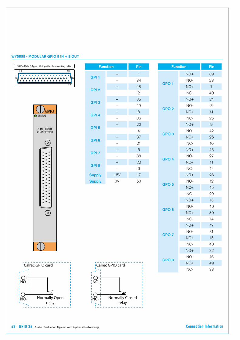
48 BR IO 36 Audio Production System with Optional Networking Connection Information
WY5858 - MODULAR GPIO 8 IN + 8 OUT
STATUS
8 IN / 8 OUTCHANGEOVER
GPIO
Function Pin
GPI 1+ 1
- 34
GPI 2+ 18
- 2
GPI 3+ 35
- 19
GPI 4+ 3
- 36
GPI 5+ 20
- 4
GPI 6+ 37
- 21
GPI 7+ 5
- 38
GPI 8+ 22
- 6
Supply +5V 17
Supply 0V 50
Function Pin
GPO 1
NO+ 39
NO- 23
NC+ 7
NC- 40
GPO 2
NO+ 24
NO- 8
NC+ 41
NC- 25
GPO 3
NO+ 9
NO- 42
NC+ 26
NC- 10
GPO 4
NO+ 43
NO- 27
NC+ 11
NC- 44
GPO 5
NO+ 28
NO- 12
NC+ 45
NC- 29
GPO 6
NO+ 13
NO- 46
NC+ 30
NC- 14
GPO 7
NO+ 47
NO- 31
NC+ 15
NC- 48
GPO 8
NO+ 32
NO- 16
NC+ 49
NC- 33
Function Pin
GPI 1+ 1- 34
GPI 2+ 18- 2
GPI 3+ 35- 19
GPI 4+ 3- 36
GPI 5+ 20- 4
GPI 6+ 37- 21
GPI 7+ 5- 38
GPI 8+ 22- 6
Supply +5 V 17Supply 0 V 50
50 Pin Male D-Type - Wiring side of connecting cable
5034
18 33
171
Normally Open relay
Calrec GPIO card
NO+
NO- Normally Closed relay
Calrec GPIO card
NC+
NC-

calrec.com Putting Sound in the Picture
BRIO 36REMOTE CONTROL AND PRODUCTION AUTOMATION

50 BR IO 36 Audio Production System with Optional Networking Remote Control and Production Automation
SW-P-08 SOURCE TO DESTINATION ROUTER REMOTE CONTROL
The Hydra2 router allows for 1-to-nsource to destination routing of Hydra2 inputs to Hydra2 outputs, without using console DSP, or control surface space. Control over input to output cross-point routing can be carried out from the Brio 36 touch screen interface, a standalone PC running the Hydra2 Organiser (H2O), or via 3rd party controllers supporting the SW-P-08 protocol.
As�well�as�physical�Hydra2�I/O�ports,�the�H2O�application�and�SW-P-08�controllers�also�have�access�to�Hydra�Patchbays,�providing�access�to�route�console�DSP�outputs�and�the�ability�to�change�sources�feeding�console�inputs.��See�the�Brio�36�User�manual�for�more�information�on�Hydra�Patchbays.
SW-P-08�is�a�well�proven�communications�protocol�with�a�very�wide�uptake�by�router�and�controller�manufacturers,�allowing�their�equipment�to�control,�or�to�be�controlled�by,�other�manufacturers’�equipment.��Although�in�widespread�use,�there�is�no�official�standard�and�there�can�be�slight�variations�in�different�manufacturers’�interpretation.��As�such,�where�possible,�Calrec�prefer�to�test�communications�with�specific�systems�before�they�are�used�for�the�first�time,�allowing�for�software�changes�to�be�made�if�required.
Please�refer�to�the�relevant�manufacturer’s�guidance�for�specific�information�relating�to�their�products.
The�following�3rd�party�SW-P-08�control�systems�have�so�far�been�factory-proven�by�Calrec:
•� L-S-B�VSM•� Colledia�BNCS•� Grass�Valley�Jupiter•� Evertz•� NVision•� Axon�Cortex•� Harris�Edge
Network�Connection�&�RedundancySW-P-08�controllers�connect�to�the�rear�panel�RJ45�sockets�labelled�‘Ethernet’�����1�or�2.
In�multi-console/multi-core�networked�systems,�the�connection�should�be�made�to�the�router�card�in�the�core�configured�as�the�Master.��Slaved�router�cores�do�not�support�SW-P-08�connections.��An�SW-P-08�connection�made�to�the�network’s�Master�Router�can�be�given�access�to�all�of�the�I/O�and�Hydra�Patchbays�on�the�network,�irrespective�of�which�core�the�I/O�connects�to�directly,�or�which�console�the�Hydra�Patchbays�are�configured�for.�
If�required,�multiple�SW-P-08�controllers�can�be�connected��simultaneously�to�the�same�RJ45�via�an�external�Ethernet�switch/hub.
The�rear�panel�Ethernet�connectors�use�a�standard�Ethernet�pin-out�and�passes�data�via�TCP/IP.�Screened�Cat5e�cabling�should�be�used�to�ensure�performance�in�electrically�noisy�environments.
For�3rd�party�controllers�that�pass�SW-P-08�data�over�RS232/RS422,�serial�to�TCP/IP�conversion�is�required.��Converter�units,�such�as�the�Perle�IOLAN�can�be�supplied�by�Calrec.
Brio�36�Connection�configurationThe�3rd�party�controller�(or�the�serial�to�TCP/IP�converter�if�used)�will�need�to�be�connected�via�one�of�the�two�ethernet�ports�and�must�be�configured�from�the�LAN�Configuration�page�in�System�Settings.
In addition to the IP address, the system will need to be configured to use TCP socket port 61000.
SW-P-08�I/O�mapping�configurationPhysical�I/O�and�Hydra�Patchbays�that�are�to�be�accessible�to�3rd�party�controllers�need�to�be�given�SW-P-08��source/destination�values�which�correspond�to�values�configured�in�the�3rd�party�controller.��SW-P-08�values�can�be�manually�typed�for�each�input�source/output�destination,�or�they�can�be�imported�(and�exported)�in�the�form�of�CSV�files.�
SW-P-08�mapping�requires�the�use�of�the�Calrec�H2O�GUI,�please�refer�to�the�H2O�user�guide�for�more�details.

CA LREC Putting Sound in the Picture 51
EMBER REMOTE CONTROL
The EMBER protocol is a sophisticated data exchange mechanism that has potential for controlling many functions across varied equipment types.
EMBER�control�has�been�incorporated�into�Calrec’s�product�range�to�allow�remote�control�functionality�over�both�mixing�consoles,�and�the�wider�Hydra2�network.
Currently,�Calrec�have�tested,�and�have�users�on-air�with�the�following�EMBER�controllers:
•� L-S-B�VSM•� Colledia�BNCS
Please�refer�to�the�relevant�manufacturer’s�guidance�for�specific�information�relating�to�their�products.
Currently,�EMBER�has�the�ability�to�control�the�following�features�when�connected�to�a�Calrec�Hydra2�network:
•� Loading�of�shows�and�user�memories�onto�control�surfaces.
•� Input�port�settings�-�mic�input�gain,�mic�input�phantom�power�switching�and�SRC�switching�on�digital�inputs.
•� View�and�edit�the�H20�based�Hydra2�I/O�box�and�port�labels.
•� Inserting�SMPTE2020�metadata�into�Hydra2�SDI�embedder�outputs—Metadata�sets�can�be�uploaded�and�edited�using�the�H20�application.�EMBER�controllers�can�select�any�of�the�available�metadata�sets�for�insertion�to,�or�removal�from�any�of�the�SDI�embedder�outputs�on�the�network.
•� EMBER�controllers�can�selectively�mute�any�of�the�audio�channels�within�the�SDI�outputs�of�Hydra2�embedders.
Network�Connection�&�RedundancyEMBER�clients�connect�to�the�rear�panel�RJ45,�labelled�‘Ethernet’,�1�or�2.�
In�multi-console/multi-core�networked�systems,�the�connection�should�be�made�to�the�Router�card�in�the�core�configured�as�the�Master.�Slaved�router�cores�do�not�support�EMBER�connections.��An�EMBER�connection�made�to�the�network’s�Master�Router�has�access�to�all�of�the�I/O�and�mixing�consoles�on�the�Hydra2�network.�
If�required,�other�controllers�can�be�connected�to�the�same�RJ45�on�the�router�at�the�same�time,�by�using�an�external�Ethernet�switch/hub.
The�rear�panel�Ethernet�connectors�use�a�standard�Ethernet�pin-out�and�passes�data�via�TCP/IP.�Screened�Cat5e�cabling�should�be�used�to�ensure�performance�in�electrically�noisy�environments.
For�3rd�party�controllers�that�pass�EMBER�data�over�RS232/RS422,�serial�to�TCP/IP�conversion�is�required.�Converter�units,�such�as�the�Perle�IOLAN�can�be�supplied�by�Calrec.
Brio�36�Connection�configurationThe�3rd�party�EMBER�controller�will�need�to�be�connected�via�one�of�the�two�ethernet�ports�and�must�be�configured�from�the�LAN�Configuration�page�in�System�Settings.
In addition to the IP address, the system will need to be configured to use TCP socket port 62000.
Control�configuration�and�enablingWith�a�valid�connection�made,�all�parameters�accessible�to�EMBER�are�made�available.��No�further�Calrec�configuration�is�required.
Brio�36�users�can�enable�or�disable�EMBER�controllers�from�being�able�to�change�their�control�surface�shows/user�memory�from�the�Brio�36�touch�screen�interface.

52 BR IO 36 Audio Production System with Optional Networking Remote Control and Production Automation
REMOTE CONTROL–CALREC SERIAL CONTROL PROTOCOL
The Calrec Serial Control Protocol (CSCP) allows for remote control over mixing console operational functions by 3rd party systems such as video switchers and production automation systems.
Several�broadcast�equipment�manufacturers�provide�serial�control�protocols�that�are�compatible�with�CSCP.�The�following�systems�are�currently�in�use�around�the�world,�actively�controlling�Calrec�audio�mixing�consoles�for�live,�on-air�applications:�
•� Ross�Overdrive�(Automated�Production�Control�system)�&�Ross�video�switchers.
•� Sony�ELC.•� Snell�Kahuna.•� Mosart.•� Grass�Valley�Ignite.
Please�refer�to�the�manufacturer’s�guidance�for�specific�information�relating�to�their�products.�
CSCP�versionsAdditional�controls�have�been�made�accessible�via�CSCP�since�it�was�first�introduced,�requiring�new�commands�to�be�added�to�the�protocol,�and�new�versions�released.��If�3rd�party�equipment�receives�CSCP�data�it�does�not�understand,�it�should�simply�ignore�it,�however�Calrec�cannot�guarantee�the�operation�of�third�parties,�and�as�such�makes�all�CSCP�versions�available�for�use�on�Brio�36.
Faders�controlled�by�CSCPThird�party�systems�with�a�CSCP�connection�to�a�Brio�36�console�have�access�to�control�and�read�back�the�status�of�up�to��72�path�faders.��Starting�with�the�lowest�numbered�fader�(usually�number�1)�on�layer�A,�up�to�the�highest�consecutively�numbered�fader,�followed�by�the�same�fader�numbers�on�layer�B�etc.�up�to�a�total�of�72�faders.�
Controls�available�via�CSCPCSCP�V1.0�allows�third�party�controllers:
•� Control�over�and�read-back�of�the�position�of�72�path�faders.
•� Read-back�of�the�72�faders’�path/port�labels.
•� Control�over�and�read-back�of�the�Cut/On�status�for�the�same�72�faders.�
•� Control�over�and�read-back�of�the�PFL�status�for�the�same�72�faders.
•� Control�over�and�read-back�of�Main�output�bus�levels�and�PFL�status.
•� Read-back�of�the�console’s�name/ID.
CSCP�V2.0�provides�the�same�functionality�as�V1.0�with�the�following�additional�features:
•� Control�over�and�status�read-back�of�the�same�72�faders’�routing�to�the�first�20�Auxiliary�output�buses�(Brio�36�has�24�Aux�buses).
•� Control�over�and�read-back�of�the�first�20�Aux�bus�output�levels�(Brio�36�has�24�Aux�buses).
•� Read-back�of�the�path�types�allocated�to�the�72�faders.
CSCP�V2.1�provides�all�the�functionality�of�V1.0�&�V2.0�along�with�the�following�additional�features:
•� Control�and�status�read-back�over�the�72�faders’�routing�to�Main�output�buses.
•� Control�and�status�read-back�over�‘Left�to�Both’�and�‘Right�to�Both’�input�controls�for�stereo�paths�on�the�same�72�faders.
ConnectionAlthough�the�protocol�is�based�on�and�passes�serial�data,�the�Calrec�connection�is�made�via�TCP/IP.��If�you�wish�to�interface�to�third�party�systems�that�only�support�point�to�point�RS232/422�serial�connections,�TCP/IP�conversion�will�be�required.��For�this�purpose,�Calrec�support�the�use�of,�and�can�supply�Perle�IOLAN�units.
Connecting�via�Corporate�LANIf�CSCP�control�is�to�be�supplied�over�a�corporate�LAN,�it�is�important�that�the�IP�address�of�the�ethernet�port�is�set�to�be�in�range�of�the�corporate�network.
Brio�36�Connection�configurationThe�CSCP�controller�will�need�to�be�connected�via�one�of�the�two�ethernet�ports�and�must�be�configured�from�the�LAN�Configuration�page�in�System�Settings.�
In addition to the IP address, both the Calrec system and the 3rd party require configuring to use the same TCP socket port. The default TCP socket port for CSCP is 49200.
If�multiple�consoles�are�to�be�controlled,�each�will�require�its�own�CSCP�connection.
User�&�boot�up�enable/disable
Once�configured,�CSCP�can�be�enabled�or�disabled�from�the�touch�screen�interface.��CSCP�settings�are�not�saved�as�part�of�the�show�or�user�memory�and�will�therefore�not�change�when�different�shows/memories�are�loaded�onto�the�control�surface.�

CA LREC Putting Sound in the Picture 53
PORTS AVAILABLE FOR SW-P-08, EMBER & CSCP CONNECTIONS ON THE BRIO 36 REAR PANEL

54 BRIO 36 Audio Production System with Optional Networking
calrec.com Putting Sound in the Picture
BRIO 36BR-IO EXTERNAL I/O RACK

56 BR IO 36 Audio Production System with Optional Networking BR-IO Ex ternal I/O Rack
BR-IO�is�a�4U�Hydra2�based�external�I/O�Rack�allowing�for�cost�effective�expansion�of�I/O�for�use�with�Brio�36�consoles.�
It�is�intended�to�be�placed�in�control/equipment�rooms,�trucks,�studios,�and�even�outdoor�use�providing�the�user�provides�appropriate�protection�against�the�elements�(flight-cases�/�covers�/�general�protection).��This�rack�has�the�same�complement�of�analogue�and�digital�I/O�that�can�be�found��in�a�Brio�36�system.
External�I/O�Rack�Audio�InterfacesThe�image�below�shows�the�BR-IO�rack�and�the�Audio�interfaces�available�to�the�user�from�this�I/O�Rack�are:-
24�x�Analogue�Mic/Line�I/Ps,�16�x�Analogue�Line�O/Ps,8�x�Digital�AES�I/Ps,�with�SRC,8�x�Digital�AES�O/Ps.��
The�Audio�Specifications�for�the�Analogue�and�Digital�inputs�and�outputs�are�the�same�as�those�built-in�to�the�Brio�36.��
These�can�be�found�in�the��“Audio�Performance�Specification”�on�page�64�
Port�Patching�IdentificationThe�BR-IO�has�it’s�own�ICON�which�appears�in�the�I/O�Boxes�patching�pages.��The�analogue�inputs�and�outputs�are�prefixed�by�the�Letter�‘A’�in�the�port�patching�pages�and�the�digital�inputs�and�outputs�are�prefixed�by�the�letter�‘B’�for�patching�purposes.�
For�example,�where�the�box�ID�is�set�to�434�then�Analogue�Mic/Line�Input�3�would�be�identified�as�434A-03.��See�below�for�a�I/O�Box�/�Port�Patching�example.
Hydra2�interfacingThe�interface�controller�on�the�right�hand�side�of�the�front�panel�of�the�unit�connects�the�I/O�to�the�optional�Hydra2�module�in�a�Brio�36�system�either�directly�or�via�a�H2Hub.
Two�Hydra2�‘Light’�based�interface�ports�are�provided�on�the�BR-IO�for�redundancy:��������Port�1�connects�to�the�Primary�H2�connection�on�a�Brio�36,��Port�2�connects�to�the�Secondary�Hydra�2�connection�on�the�same�Brio�36.��Multiple�BR-IO�units�may�be�added�via�a�H2�Hub�along�with�other�I/O�boxes�from�the�Hydra2�range.
Hydra2�based�network�components�interface�via�pluggable�SFP�modules,�the�correct�type�of�SFP�should�be�ordered�to�match�the�installation�requirements.
EXTERNAL I/O RACK FOR BRIO 36
AD6300 - BR-IO EXTERNAL I/O RACK.
BR-IO PORT PATCHING EXAMPLE

CA LREC Putting Sound in the Picture 57
BR-IO�box�ID�settingThe�ID�for�BR-IO�boxes�is�set�using�the�DIP�switches�on�the�controller�card�and�is�only�accessible�by�powering�the�BR-IO�unit�off�and�removing�the�access�panel�on�the�lid�of�the�BR-IO�box.��Ensure�ESD�precautions�are�observed�before�handling�any�BR-IO�box�cards.
ID�switches�on�the�I/O�controller�are�orientated�as�shown�in�the�image�below�left.��The�illustration�on�this�page�shows�the�ID�switch�on�the�modular�I/O�controller�card�from�the�top�view.��The�decimal�value�of�39�is�used�for�this�example,�and�as�with�all�externally�connected�I/O,��each�I/O�box�needs�a�unique�ID�to�function�correctly.
Note, always use a non-conductive tool to set the DIP switches to avoid damaging the card.
BR-IO HYDRA2 ’LIGHT’ INTERFACE CONTROLLER
I/O box reset
Wordclock sync output (BNC)
Serial USB - factory config / diagnostics only
SFP - Hydra2 port 1 (primary)
SFP - Hydra2 port 2 (secondary)
Status LEDsUnder�normal�operation:�
STATUS���-�ON�solid�greenH_ACT� �-�OFFHB1�� �-�Flashing�yellowHB2�� �-�Flashing�yellowSOFT� �-�Flashing�yellowCTRL1� �-�ON�solid�yellowCTRL2� �-�ON�solid�yellowAUD1� �-�ON�solid�yellowAUD2� �-�OFFPSU� �-�OFF��(red�if�fail)48V� �-�OFF��(red�if�fail)FAN� �-�OFF��(red�if�fail)
Hydra port LEDsUnder�normal�operation:
Upper�LED�-�Flashing�green�Lower�LED�-�ON�solid�yellow
1 2 4 8 16 32 64 128
10
10
BR-IO�box�Power�SupplyBR-IO�contains�two�power�supply�units�which�are�supplied�with�AC�power�by�two�independent�(IEC�60320-1�C13/C14�couplers).��
These�dual�power�supplies�provide�full�power�redundancy,�a�feature�of�all�Calrec�products.��
Although�BR-IO�will�run�with�only�one�PSU�powered�on,�it�is�recommended�that,�to�ensure�power�redundancy,�these�two�IEC�inlets�should�be�supplied�by�separate�AC�power�supplies.�
A�PSU�failure�or�a�loss�of�AC�power�input�will�generate�a�system�status�error�message.
The�two�PSU’s�employ�load�sharing,�if�one�PSU�fails,�the�other�will�automatically�take�over�the�full�load�with�no�loss�of�audio�or�operation.�
Disconnecting�the�PSUsThe�BR-IO�rack�does�not�contain�a�separate�mains�power�switch.��To�safely�disconnect�the�mains�power�both�IEC�connectors�need�to�be�removed�from�the�rear�of�the�unit.
BR-IO CONTROLLER ID SWITCHES
Front�Panel
Reference�to�Power�/�Environmental�SpecificationBR-IO�has�it’s�own�Power�/�Environmental�specification�which�can�be�found�in�the�bottom�half�of�the�”Power/Environmental�Specifications”�on�page�61.

58 BRIO 36 Audio Production System with Optional Networking

calrec.com Putting Sound in the Picture
BRIO 36SPECIFICATIONS
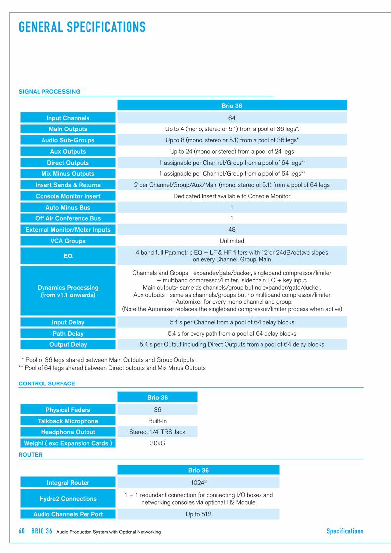
60 BR IO 36 Audio Production System with Optional Networking Specif ications
CONTROL SURFACE
Brio 36
Physical Faders 36
Talkback Microphone Built-In
Headphone Output Stereo,�1/4’�TRS�Jack
Weight ( exc Expansion Cards ) 30kG
Brio 36
Integral Router 10242
Hydra2 Connections1�+�1�redundant�connection�for�connecting�I/O�boxes�and�
networking�consoles�via�optional�H2�Module
Audio Channels Per Port Up�to�512
ROUTER
GENERAL SPECIFICATIONS
Brio 36
Input Channels 64
Main Outputs Up�to�4�(mono,�stereo�or�5.1)�from�a�pool�of�36�legs*.
Audio Sub-Groups Up�to�8�(mono,�stereo�or�5.1)�from�a�pool�of�36�legs*
Aux Outputs Up�to�24�(mono�or�stereo)�from�a�pool�of�24�legs
Direct Outputs 1�assignable�per�Channel/Group�from�a�pool�of�64�legs**
Mix Minus Outputs 1�assignable�per�Channel/Group�from�a�pool�of�64�legs**
Insert Sends & Returns 2�per�Channel/Group/Aux/Main�(mono,�stereo�or�5.1)�from�a�pool�of�64�legs
Console Monitor Insert Dedicated�Insert�available�to�Console�Monitor
Auto Minus Bus 1
Off Air Conference Bus 1
External Monitor/Meter Inputs 48
VCA Groups Unlimited
EQ4�band�full�Parametric�EQ�+�LF�&�HF�filters�with�12�or�24dB/octave�slopes��������������������������������������
on�every�Channel,�Group,�Main�����������������
Dynamics Processing(from v1.1 onwards)
Channels�and�Groups�-�expander/gate/ducker,�singleband�compressor/limiter�����������������+�multiband�compressor/limiter,��sidechain�EQ�+�key�input.
Main�outputs-�same�as�channels/group�but�no�expander/gate/ducker.Aux�outputs�-�same�as�channels/groups�but�no�multiband�compressor/limiter
+Automixer�for�every�mono�channel�and�group.��������������������������������������������������������������������(Note�the�Automixer�replaces�the�singleband�compressor/limiter�process�when�active)
Input Delay 5.4�s�per�Channel�from�a�pool�of�64�delay�blocks
Path Delay 5.4�s�for�every�path�from�a�pool�of�64�delay�blocks
Output Delay 5.4�s�per�Output�including�Direct�Outputs�from�a�pool�of�64�delay�blocks
��*�Pool�of�36�legs�shared�between�Main�Outputs�and�Group�Outputs�������������������������������������������������**�Pool�of�64�legs�shared�between�Direct�outputs�and�Mix�Minus�Outputs
SIGNAL PROCESSING

CA LREC Putting Sound in the Picture 61
POWER/ENVIRONMENTAL SPECIFICATIONS
Both the control surface and external I/O rack have two IEC AC power inlets feeding two sets of internal power distribution. Although both the control surface and external I/O rack will operate with one inlet supply we recommend both inlets are powered. This will ensure continued operation should a PSU or AC source fail. The operating AC supply voltage is 100 V - 240 V +/-10%.
The�average�half-cycle�r.m.s�inrush�current�per�inlet:•� On�initial�switch-on�<5�A•� After�5�s�interruption�<10�A
CONTROL SURFACE
BR-IO EXTERNAL I/O RACK
Brio 36 240V Operation 115V Operation 100V Operation
Supply Current 0.92�A 1.35�A 1.55�A
Power Factor 0.71 0.98 0.99
Power Dissipation (Heat) - Maximum Brightness
157�W 152�W 153�W
Power Dissipation (Heat) - Dark Mode
134�W 126�W 126�W
Cooling
The�control�surface�is�cooled�by�a�quiet�outtake�fan�on�the�rear�of�the�console.�The�air�intake�is�on�the�side�vents�of�the�console.��
At�least�50mm�(2’)�clearance�should�be�maintained�for�these�vents.�If�the�sides�are�obstructed,�the�trims�will�pull�air�from�below�and�rear.
Operating Ambient Air Temperature
0°C�-�40°C�
BR-IO 240V Operation 115V Operation 100V Operation
Supply Current 0.33�A 0.53�A 0.60�A
Power Factor 0.57 0.77 0.78
Power Dissipation (Heat) 46�W 47�W 47�W
Cooling
This�4U�Rack�is�cooled�by�a�quiet�outtake�fan�on�the�rear�of�the�unit.�The�air�intake�is�on�the�side�vents�of�the�unit.��
The�side�panels�of�the�BR-IO�unit�should�be�unobstructed�with�at�least�50mm�(2’)�clearance�to�allow�airflow.�No�clearance�is�required�above�or�below�the�unit.
Operating Ambient Air Temperature
0°C�-�40°C�
Weight 8.6kG
Note that Brio 36 is a self contained unit and the processing core is built into the console.

62 BR IO 36 Audio Production System with Optional Networking Specif ications
HYDRA2 FIXED FORMAT I/O
Fixed Format I/O
Power
All�fixed�format�Hydra2�I/O�units�have�two�IEC�AC�power�inlets�and�are�fitted�with�dual�power�supplies.��Units�will�be�fully�functional�on�one�PSU,�however�both�should�be�fed�where�possible�from�separate�sources�to�provide�redundancy�against�both�PSU�failure�and�external�power�loss.
The�operating�AC�supply�voltage�is�100�V�-�240�V�+/-10%.
The�peak�inrush�current�is�limited�(cold�start).��Figures�are�available�for�all�units.��This�reduces�the�chance�of�a�nuisance�trip�or�fuse�blow�from�power�up.��The�RMS�quiescent�current�figures�are�specified�on�the�rating�label�for�all�types�of�I/O�box�and�are�available�within�the�individual�data�sheets�in�the�Hydra2�Installation�Manual.
Power Factor
All�fixed�format�Hydra2�I/O�units�require�less�than�75W�of�input�power.��The�internal�power�supplies�fitted�have�passive�filtering�(as�opposed�to�active�power�factor�correction)�to�reduce�the�harmonics�to�within�the�limits�of�the�standard�EN61000-3-2.��At�the�time�of�writing�the�standard�does�not�apply�to�equipment�<75W.�If�the�lower�limit�is�ever�reduced�the�units�will�be�compliant�and�as�such�are�future�proof.
Heat Output and Efficiency
The�Heat�output�from�fixed�format�Hydra2�I/O�units�depends�on�the�supply�voltage�and�loading.��Typically�it�is�0.55�times�the�RMS�VA�(Volts�x�Amperes)�at�230V�and�0.7�times�the�RMS�VA�at�115V.��Heat�output�figures�are�available�for�all�types�of�I/O�box.
The�low�power�PSU�efficiency�is�again�dependant�on�supply�voltage�and�loading,�generally�>70%.
Cooling
All�fixed�format�Hydra2�I/O�units�of�2U�or�greater�are�cooled�under�control�with�fan�assistance.�Operation�is�not�dependant�on�the�fan;�it�is�there�to�extend�the�operating�life�of�the�unit.��There�is�an�80mm�low�power,�low�speed�and�low�noise�fan�mounted�to�the�right�hand�side�panel�of�each�unit�venting�air.��Fan�speed�is�monitored�and�system�status�warnings�are�generated�if�fans�slow�or�fail.��Air�is�drawn�in�through�the�left�hand�side�panel.�
1U�Hydra2�I/O�boxes�do�not�require�fan�assistance�having�sufficient�surface�area�to�radiate�heat�adequately.The�side�panels�of�all�fixed�format�Hydra2�I/O�units�should�be�unobstructed�with�at�least�50mm�(2’)�clearance�to�allow�airflow.�No�clearance�is�required�above�or�below�the�unit.
I/O�units�may�be�mounted�in�an�open�bay�providing�the�ambient�air�temperature�is�within�limits�(see�below).�The�units�may�also�be�housed�in�any�air�conditioned�bay.
Acoustic Noise <27�dB�SPL�(A-weighted,�1m�from�front).
Operating Ambient Air Temperature
0°C�-�40°C
Relative Humidity 5%�-�80%�Non-Condensing

CA LREC Putting Sound in the Picture 63
HYDRA2 MODULAR I/O
Hydra2 Modular I/O
Power
Modular�Hydra2�I/O�frames�are�fitted�with�dual�power�supplies�and�have�2�IEC�AC�power�input�connectors.��Units�will�be�fully�functional�on�one�PSU,�however�both�should�be�fed�where�possible�from�separate�sources�to�provide�redundancy�against�both�PSU�failure�and�external�power�loss.
The�operating�AC�supply�voltage�is�100�V�-�240�V�+/-10%.
The�peak�inrush�current�is�limited�(cold�start).��This�reduces�the�chance�of�a�nuisance�trip�or�fuse�blow�from�power�up.��The�RMS�quiescent�and�peak�inrush�current�figures�are�dependant�upon�the�quantity�and�type�of�I/O�cards�fitted.��Please�refer�to�the�Hydra2�installation�manual�for�more�details�on�modular�I/O.
Heat Output and EfficiencyThe�Heat�output�from�modular�Hydra2�I/O�units�depends�upon�the�quantity�and�card�types�fitted,�please�refer�to�the�Hydra2�installation�manual�for�more�detail�on�modular�I/O.
Cooling
Fans�mounted�to�the�PSUs�at�the�back�of�the�core�draw�air�through�the�PSUs�and�the�core�itself.��Air�is�drawn�up�through�the�base�of�the�core�which�is�recessed�to�allow�air�to�enter�through�the�side,�and�for�the�units�to�be�mounted�with�no�clearance�above�or�below.��The�bottom�of�the�sides�of�the�modular�I/O�box�should�be�unobstructed�with�at�least�50mm�(2’)�clearance�to�allow�airflow.
Modular�I/O�units�may�be�mounted�in�an�open�bay�providing�the�ambient�air�temperature�is�within�limits�(see�below).��The�units�may�also�be�housed�in�air�conditioned�bays.
Acoustic Noise <27�dB�SPL�(A-weighted,�1m�from�front).
Operating Ambient Air Temperature
0°C�-�35°C
Relative Humidity 5%�-�80%�Non-Condensing

64 BR IO 36 Audio Production System with Optional Networking Specif ications
AUDIO PERFORMANCE SPECIFICATION
BUILT-IN AES3ID UNBALANCED DIGITAL INPUTS
BUILT-IN AES3ID UNBALANCED DIGITAL OUTPUTS
BUILT-IN ANALOGUE INPUT SPECS
Format AES/EBU�(AES3)�24-bit.��Also�suitable�for�use�with�SPDIF�(IEC958�type�2)�signals
Interface 75�Ohm�unbalanced�(BNC),�0.3V-1.2V�Pk-Pk
Sample Rate Conversion 24-Bit�switchable�on�all�AES�inputs
SRC THD+N -116dB�@�1kHz,�0.00015%
Format AES/EBU�(AES3)�24-bit
Interface 75�Ohm�unbalanced�1V�Pk-Pk�(nominal)�into�75�Ohm�load�(BNC)
Jitter <0.018UI�(3.2ns)�peak
Analogue - Digital Conversion
24�Bit
Input Electronically�Balanced
Input Impedance 5.4k�Ohms�for�mic/line�level�gain�settings
Sensitivity +18�/�-78dB�for�Mic/Line�Inputs
Equivalent Input Noise -126dB,�22kHz�bandwidth,�max�gain�(150�Ohm�source)
Distortion-1dBFS�@�1kHz�-�Better�than�0.003%-20dBFS�@�1kHz�-�Better�than�0.036%-60�dBFS�@�1kHz�-�Better�than�0.2%
Frequency Response 20Hz�to�20kHz�+/-�0.5dB�on�Mic/Line�Inputs
Input CMR(Common Mode Rejection)
>75dB�(Typical�85dB)�on�Mic/Line�inputs
Notes
Analogue�input�for�0dBFS�can�be�pre-set�globally�to�+28,�+24,�+22,�+20,�+18�or�+15dBUPre-fader�headroom�on�mic�inputs�is�adjustable�globally�from�+24�to�+36dB�in�2dB�stepsFor�analogue�inputs/outputs�the�system�can�handle�analogue�levels�of�up�to�+27�dBu�from�analogue�input�to�analogue�output�at�line�upThese�levels�must�be�attenuated�in�the�system�before�they�are�fed�to�digital�outputs
BUILT-IN ANALOGUE OUTPUT SPECS
Digital - Analogue Conversion
24�Bit
Output Balance Electronically�balanced.�20Hz�to�20KHz,�better�than�-35dB,�typically�-45dB
Output Impedance <40�Ohms
Distortion-1dBFS�@�1kHz�-�Better�than�0.002%-20dBFS�@�1kHz�-�Better�than�0.002%-40�dBFS�@�1kHz�-�Better�than�0.2%
Frequency Response 20Hz�to�20kHz�+/-�0.25dB
Notes Analogue�output�for�0dBFS�matches�input�setting�into�>1kOhms�(+24dBu�max�into�600�Ohms)

CA LREC Putting Sound in the Picture 65
BUILT-IN SYNCHRONISATION INPUTS
BUILT-IN AUDIO PERFORMANCE DATA
Digital to Digital (AES3) Distortion
-1dBFS,�20Hz�to�10kHz�-�Better�than�0.0002%
Digital to Digital (AES3 with SRC) Distortion
-1dBFS,�20Hz�to�10kHz�-�Better�than�0.0002%
Frequency Response(Analogue Input to Output)
20Hz�to�20kHz�+/-�0.25dB
48kHz Synchronisation
NTSC/PAL�VideoTri-LevelInternal�Crystal�ReferenceTTL�Wordclock�(48kHz)�x2AES/EBU�(AES3)�Digital�Input�(48kHz)�x�2
BUILT-IN LATENCY @ 48KHZ SAMPLE RATE *
From To Via Samples =ms
AES3 inputs (SRC off)
AES3�Outputs Port�to�port 18 0.375
AES3�Outputs channel,�group,�and�aux�or�main�output 30 0.625
Analogue�Outputs
Port�to�port 65 1.354
Analogue�Outputs
channel,�group,�and�aux�or�main�output 77 1.604
Turning�SRC�on�adds�to�the�above: +�39 +�0.813
Mic/Line inputs
AES3�Outputs Port�to�port 43 0.896
AES3�Outputs channel,�group,�and�aux�or�main�output 55 1.146Analogue�Outputs
Port�to�port 90 1.875
Analogue�Outputs�
channel,�group,�and�aux�or�main�output 102 2.125
*�Note:��These�latency�figures�are�for�a�system�with�a�single�Router/DSP�core�rack.��Add�2�samples�for�each�input,�and�2�samples�for�each�output,�for�each�additional�core�rack�in�the�relevant�part�of�the�signal�path.

66 BR IO 36 Audio Production System with Optional Networking Specif ications
DYNAMIC RANGE FOR BUILT-IN ANALOGUE AND AES3 (INPUTS)
Built-In Analogue INPUTS system�set�for
to Digital Outputs with 0 dB gain +18�dBu�=�0�dBFS 108�dB�
+24�dBu�=�0�dBFS 114�dB�
to Analogue Outputs with 0 dB gain * N/A 112�dB�
Built-In AES3 UNBALANCED DIGITAL INPUTS
system�set�for SRC�on�I/P SRC�on�I/P
to Digital Outputs with 0 dB gain N/A off 141�dB� on 134�dB�
to Analogue Outputs with 0 dB gain +18�dBu�=�0�dBFS off 109�dB�� on 109�dB�
+24�dBu�=�0�dBFS off 115�dB�� on 115�dB�
*�The�analogue�to�analogue�dynamic�range�is�achieved�because�the�system�can�accept�analogue�signals�of�up�to�+28�dBu�from�input�to�output�at�0�dB�gain.��Obviously,�an�analogue�input�of�up�to�+28�dBu�must�be�attenuated�to�output�this�digitally,�but�this�attenuation�will�maintain�the�Dynamic�Range�of�the�input,�as�the�analogue�input�noise�will�be�attenuated�by�the�same�amount�as�the�signal,�and�the�analogue�input�noise�will�still�be�dominant�above�the�noise�floor�of�the�digital�system.
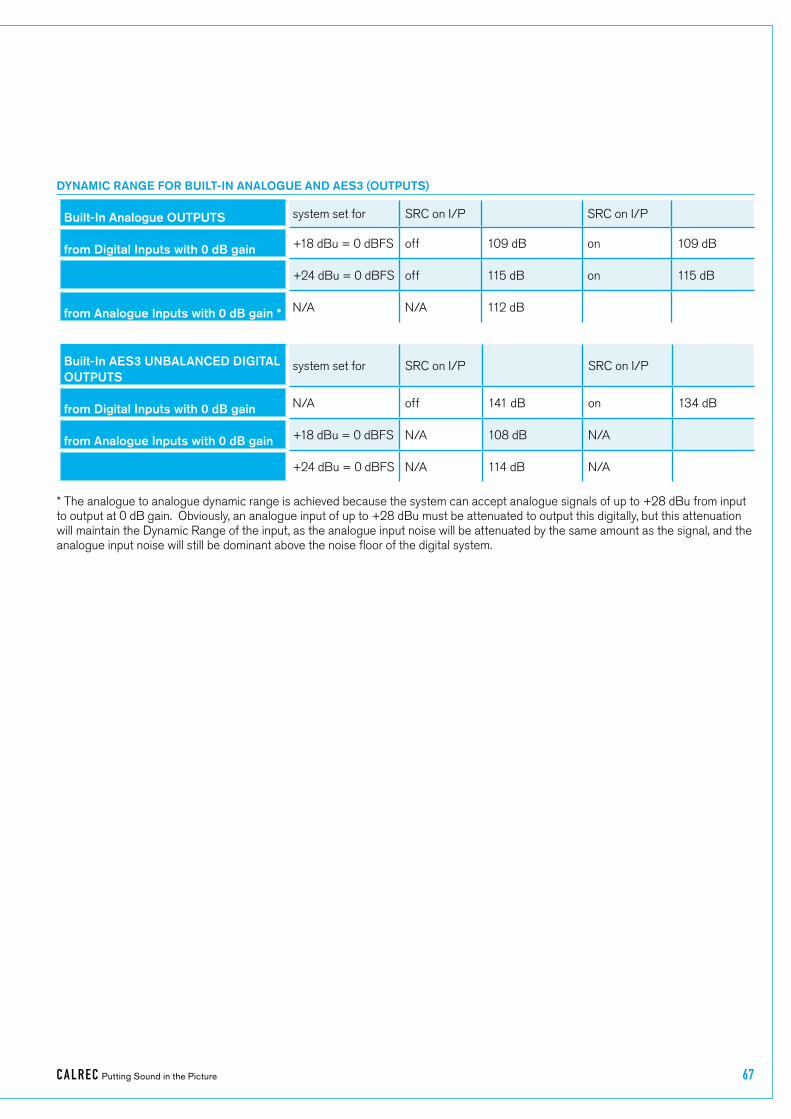
CA LREC Putting Sound in the Picture 67
Built-In Analogue OUTPUTS system�set�for SRC�on�I/P SRC�on�I/P
from Digital Inputs with 0 dB gain +18�dBu�=�0�dBFS off 109�dB� on 109�dB
+24�dBu�=�0�dBFS off 115�dB� on 115�dB
from Analogue Inputs with 0 dB gain * N/A N/A 112�dB�
DYNAMIC RANGE FOR BUILT-IN ANALOGUE AND AES3 (OUTPUTS)
Built-In AES3 UNBALANCED DIGITAL OUTPUTS
system�set�for SRC�on�I/P SRC�on�I/P
from Digital Inputs with 0 dB gain N/A off 141�dB� on 134�dB�
from Analogue Inputs with 0 dB gain +18�dBu�=�0�dBFS N/A 108�dB�� N/A
+24�dBu�=�0�dBFS N/A 114�dB�� N/A
*�The�analogue�to�analogue�dynamic�range�is�achieved�because�the�system�can�accept�analogue�signals�of�up�to�+28�dBu�from�input�to�output�at�0�dB�gain.��Obviously,�an�analogue�input�of�up�to�+28�dBu�must�be�attenuated�to�output�this�digitally,�but�this�attenuation�will�maintain�the�Dynamic�Range�of�the�input,�as�the�analogue�input�noise�will�be�attenuated�by�the�same�amount�as�the�signal,�and�the�analogue�input�noise�will�still�be�dominant�above�the�noise�floor�of�the�digital�system.
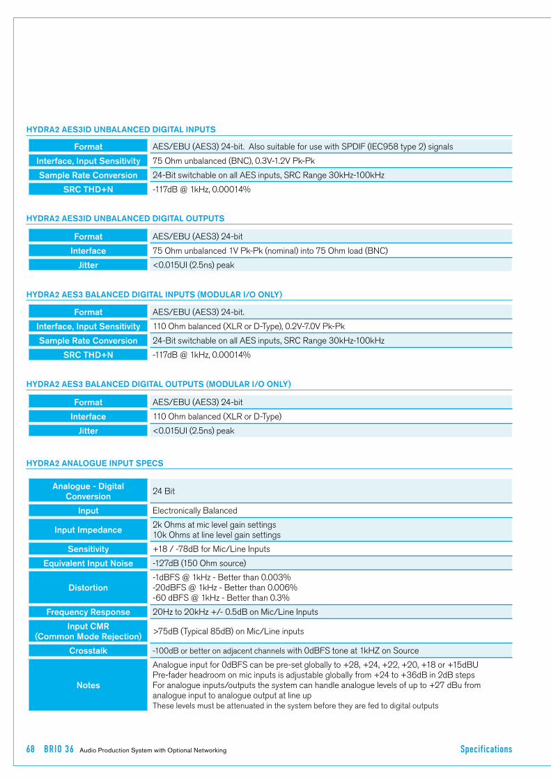
68 BR IO 36 Audio Production System with Optional Networking Specif ications
HYDRA2 AES3ID UNBALANCED DIGITAL INPUTS
HYDRA2 AES3ID UNBALANCED DIGITAL OUTPUTS
HYDRA2 ANALOGUE INPUT SPECS
Format AES/EBU�(AES3)�24-bit.��Also�suitable�for�use�with�SPDIF�(IEC958�type�2)�signals
Interface, Input Sensitivity 75�Ohm�unbalanced�(BNC),�0.3V-1.2V�Pk-Pk
Sample Rate Conversion 24-Bit�switchable�on�all�AES�inputs,�SRC�Range�30kHz-100kHz
SRC THD+N -117dB�@�1kHz,�0.00014%
Format AES/EBU�(AES3)�24-bit
Interface 75�Ohm�unbalanced�1V�Pk-Pk�(nominal)�into�75�Ohm�load�(BNC)
Jitter <0.015UI�(2.5ns)�peak
HYDRA2 AES3 BALANCED DIGITAL INPUTS (MODULAR I/O ONLY)
HYDRA2 AES3 BALANCED DIGITAL OUTPUTS (MODULAR I/O ONLY)
Format AES/EBU�(AES3)�24-bit.
Interface, Input Sensitivity 110�Ohm�balanced�(XLR�or�D-Type),�0.2V-7.0V�Pk-Pk
Sample Rate Conversion 24-Bit�switchable�on�all�AES�inputs,�SRC�Range�30kHz-100kHz
SRC THD+N -117dB�@�1kHz,�0.00014%
Format AES/EBU�(AES3)�24-bit
Interface 110�Ohm�balanced�(XLR�or�D-Type)
Jitter <0.015UI�(2.5ns)�peak
Analogue - Digital Conversion
24�Bit
Input Electronically�Balanced
Input Impedance2k�Ohms�at�mic�level�gain�settings10k�Ohms�at�line�level�gain�settings
Sensitivity +18�/�-78dB�for�Mic/Line�Inputs
Equivalent Input Noise -127dB�(150�Ohm�source)
Distortion-1dBFS�@�1kHz�-�Better�than�0.003%-20dBFS�@�1kHz�-�Better�than�0.006%-60�dBFS�@�1kHz�-�Better�than�0.3%
Frequency Response 20Hz�to�20kHz�+/-�0.5dB�on�Mic/Line�Inputs
Input CMR(Common Mode Rejection)
>75dB�(Typical�85dB)�on�Mic/Line�inputs
Crosstalk -100dB�or�better�on�adjacent�channels�with�0dBFS�tone�at�1kHZ�on�Source
Notes
Analogue�input�for�0dBFS�can�be�pre-set�globally�to�+28,�+24,�+22,�+20,�+18�or�+15dBUPre-fader�headroom�on�mic�inputs�is�adjustable�globally�from�+24�to�+36dB�in�2dB�stepsFor�analogue�inputs/outputs�the�system�can�handle�analogue�levels�of�up�to�+27�dBu�from�analogue�input�to�analogue�output�at�line�upThese�levels�must�be�attenuated�in�the�system�before�they�are�fed�to�digital�outputs

CA LREC Putting Sound in the Picture 69
HYDRA2 SYNCHRONISATION INPUTS
HYDRA2 AUDIO PERFORMANCE DATA
HYDRA2 ANALOGUE OUTPUT SPECS
Digital - Analogue Conversion
24�Bit
Output Balance Electronically�balanced.�20Hz�to�20KHz,�better�than�-35dB,�typically�-45dB
Output Impedance <40�Ohms
Distortion-1dBFS�@�1kHz�-�Better�than�0.006%-20dBFS�@�1kHz�-�Better�than�0.003%-60�dBFS�@�1kHz�-�Better�than�0.3%
Frequency Response 20Hz�to�20kHz�+/-�0.25dB
Notes Analogue�output�for�0dBFS�matches�input�setting�into�>1kOhms�(+24dBu�max�into�600�Ohms)
Digital to Digital (AES3) Distortion
-1dBFS,�20Hz�to�10kHz�-�Better�than�0.0001%
Digital to Digital (AES3 with SRC) Distortion
-1dBFS,�20Hz�to�10kHz�-�Better�than�0.0002%
Frequency Response(Analogue Input to Output)
20Hz�to�20kHz�+/-�0.5dB
48KHz Synchronisation
NTSC/PAL�VideoTri-LevelInternal�Crystal�ReferenceTTL�Wordclock�(48kHz)AES/EBU�(AES3)�Digital�Input�(48kHz)
HYDRA2 LATENCY @ 48KHZ / 96KHZ SAMPLE RATE *
From To Via Samples @48kHz @96kHz
AES3 inputs (SRC off)
AES3�Outputs Port�to�port 18 0.376ms 0.188ms
AES3�Outputs channel,�group,�and�aux�or�main�output 30 0.626ms 0.313ms
Analogue�Outputs
Port�to�port 65 1.354ms 0.677ms
Analogue�Outputs
channel,�group,�and�aux�or�main�output 77 1.604ms 0.802ms
Turning�SRC�on�adds�to�the�above: +�39 +�0.814ms +�0.407ms
Mic/Line inputs
AES3�Outputs Port�to�port 43 0.896ms 0.448ms
AES3�Outputs channel,�group,�and�aux�or�main�output 55 1.146ms 0.573msAnalogue�Outputs
Port�to�port 90 1.876ms 0.938ms
Analogue�Outputs�
channel,�group,�and�aux�or�main�output 102 2.126ms 1.063ms
*�Note:��These�latency�figures�are�for�a�system�with�a�single�Router/DSP�core�rack.��Add�2�samples�for�each�input,�and�2�samples�for�each�output,�for�each�additional�core�rack�in�the�relevant�part�of�the�signal�path.
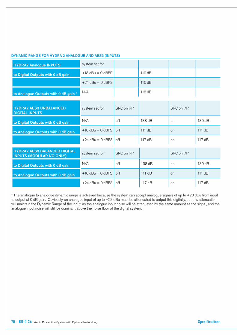
70 BR IO 36 Audio Production System with Optional Networking Specif ications
DYNAMIC RANGE FOR HYDRA 2 ANALOGUE AND AES3 (INPUTS)
HYDRA2 Analogue INPUTS system�set�for
to Digital Outputs with 0 dB gain +18�dBu�=�0�dBFS 110�dB�
+24�dBu�=�0�dBFS 116�dB�
to Analogue Outputs with 0 dB gain * N/A 118�dB�
HYDRA2 AES3 UNBALANCED DIGITAL INPUTS
system�set�for SRC�on�I/P SRC�on�I/P
to Digital Outputs with 0 dB gain N/A off 138�dB� on 130�dB�
to Analogue Outputs with 0 dB gain +18�dBu�=�0�dBFS off 111�dB�� on 111�dB�
+24�dBu�=�0�dBFS off 117�dB�� on 117�dB�
HYDRA2 AES3 BALANCED DIGITAL INPUTS (MODULAR I/O ONLY)
system�set�for SRC�on�I/P SRC�on�I/P
to Digital Outputs with 0 dB gain N/A off 138�dB� on 130�dB�
to Analogue Outputs with 0 dB gain +18�dBu�=�0�dBFS off 111�dB�� on 111�dB�
+24�dBu�=�0�dBFS off 117�dB�� on 117�dB�
*�The�analogue�to�analogue�dynamic�range�is�achieved�because�the�system�can�accept�analogue�signals�of�up�to�+28�dBu�from�input�to�output�at�0�dB�gain.��Obviously,�an�analogue�input�of�up�to�+28�dBu�must�be�attenuated�to�output�this�digitally,�but�this�attenuation�will�maintain�the�Dynamic�Range�of�the�input,�as�the�analogue�input�noise�will�be�attenuated�by�the�same�amount�as�the�signal,�and�the�analogue�input�noise�will�still�be�dominant�above�the�noise�floor�of�the�digital�system.

CA LREC Putting Sound in the Picture 71
HYDRA2 Analogue OUTPUTS system�set�for SRC�on�I/P SRC�on�I/P
from Digital Inputs with 0 dB gain +18�dBu�=�0�dBFS off 111�dB� on 111�dB
+24�dBu�=�0�dBFS off 117�dB� on 117�dB
from Analogue Inputs with 0 dB gain * N/A N/A 118�dB�
DYNAMIC RANGE FOR HYDRA 2 ANALOGUE AND AES3 (OUTPUTS)
HYDRA2 AES3 UNBALANCED DIGITAL OUTPUTS
system�set�for SRC�on�I/P SRC�on�I/P
from Digital Inputs with 0 dB gain N/A off 138�dB� on 130�dB�
from Analogue Inputs with 0 dB gain +18�dBu�=�0�dBFS N/A 110�dB�� N/A
+24�dBu�=�0�dBFS N/A 116�dB�� N/A
HYDRA2 AES3 BALANCED DIGITAL OUTPUTS (MODULAR I/O ONLY)
system�set�for SRC�on�I/P SRC�on�I/P
from Digital Inputs with 0 dB gain N/A off 138�dB� on 130�dB�
from Analogue Inputs with 0 dB gain +18�dBu�=�0�dBFS N/A 110�dB�� N/A
+24�dBu�=�0�dBFS N/A 116�dB�� N/A
*�The�analogue�to�analogue�dynamic�range�is�achieved�because�the�system�can�accept�analogue�signals�of�up�to�+28�dBu�from�input�to�output�at�0�dB�gain.��Obviously,�an�analogue�input�of�up�to�+28�dBu�must�be�attenuated�to�output�this�digitally,�but�this�attenuation�will�maintain�the�Dynamic�Range�of�the�input,�as�the�analogue�input�noise�will�be�attenuated�by�the�same�amount�as�the�signal,�and�the�analogue�input�noise�will�still�be�dominant�above�the�noise�floor�of�the�digital�system.

(926-218 Iss.3)
Calrec�Audio�LtdNutclough�Mill�Hebden�Bridge�West�Yorkshire�England��UK�HX7�8EZ
Tel��+44�(0)1422�842159�Fax�+44�(0)1422�845244�Email��[email protected]
calrec.com