brief description of kr 4 and kr 7 controllers - klingenburg-usa.com · 1 brief description of kr 4...
TRANSCRIPT
1
Brief description of KR 4 and KR 7 controllersE N E R G Y R E C O V E R Y
1. Function of the controller
2. Terminal connections
3. Technical data
4. Initial operation
5. Manual mode / external mode
6. Trouble-shooting and fault messages
7. Safety and precautions
Page 2
Page 4
Page 5
Page 6
Page 7
Page 10
Page 14
32
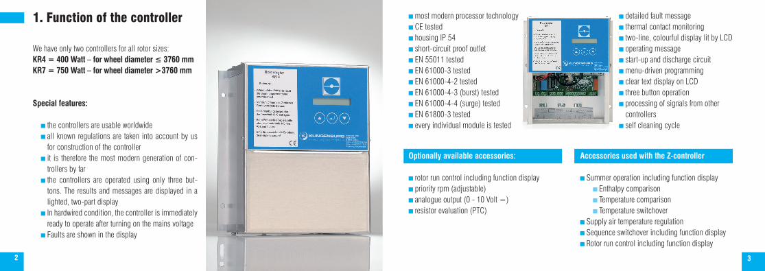
1. Function of the controller
We have only two controllers for all rotor sizes:KR4 = 400 Watt – for wheel diameter ≤ 3760 mmKR7 = 750 Watt – for wheel diameter >3760 mm
Special features:
the controllers are usable worldwide all known regulations are taken into account by us
for construction of the controller it is therefore the most modern generation of con-
trollers by far the controllers are operated using only three but-
tons. The results and messages are displayed in a lighted, two-part display
In hardwired condition, the controller is immediately ready to operate after turning on the mains voltage
Faults are shown in the display
most modern processor technology CE tested housing IP 54 short-circuit proof outlet EN 55011 tested EN 61000-3 tested EN 61000-4-2 tested EN 61000-4-3 (burst) tested EN 61000-4-4 (surge) tested EN 61800-3 tested every individual module is tested
detailed fault message thermal contact monitoring two-line, colourful display lit by LCD operating message start-up and discharge circuit menu-driven programming clear text display on LCD three button operation processing of signals from other controllers
self cleaning cycle
Optionally available accessories:
rotor run control including function display priority rpm (adjustable) analogue output (0 - 10 Volt =) resistor evaluation (PTC)
Accessories used with the Z-controller
Summer operation including function display Enthalpy comparison Temperature comparison Temperature switchover
Supply air temperature regulation Sequence switchover including function display Rotor run control including function display
54
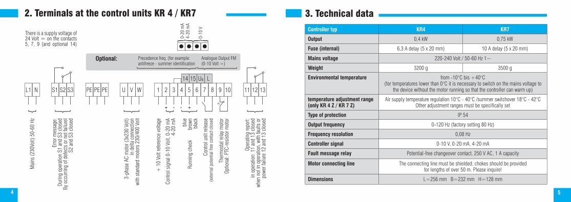
2. Terminals at the control units KR 4 / KR7
L1 N S1 S2 S3 PE PE PE U V W 1 2 3 4 5 6 7 8 9 10 11 12 13
Mai
ns (2
30Vo
lt) 5
0-60
Hz
Erro
r mes
sage
:Du
ring
oper
atio
n S1
and
S3
clos
edBy
occ
urrin
g of
def
ects
or n
et fa
ilure
l S2
and
S3
clos
ed
3-ph
ase
AC m
otor
(3x2
30 V
olt)
in d
elta
con
nect
ion
with
sta
ndar
d m
otor
s 23
0/40
0 Vo
lt
+ 1
0 Vo
lt re
fere
nce
volta
ge
Cont
rol s
igna
l 0-1
0 Vo
lt, 0
-20
mA
4-20
mA
+ - - +bl
ueRu
nnin
g ch
eck
bro
wnbl
ack
Cont
rol u
nit r
elea
se(e
xtern
al p
oten
tial f
ree
cont
act c
lose
d
Ther
mos
tat r
elay
mot
orOp
tiona
l: PT
C-re
sist
or m
otor
Oper
atin
g re
port:
in o
pera
tion:
11
and
13 c
lose
dwh
en n
ot in
ope
ratio
n, w
ith fa
ults
or
powe
r fai
lure
12
and
13 c
lose
d
14 15 Ua L
Analogue Output FM(0-10 Volt =)
Precedence freq. (for example: antifreeze - summer identification
Optional:
0-20
mA
4-20
mA
0-10
V
There is a supply voltage of 24 Volt = on the contacts 5, 7, 9 (and optional 14)
3. Technical data
Controller typ KR4 KR7
Output 0,4 kW 0,75 kW
Fuse (internal) 6,3 A delay (5 x 20 mm) 10 A delay (5 x 20 mm)
Mains voltage 220-240 Volt / 50-60 Hz 1~
Weight 3200 g 3500 g
Environmental temperature from -10°C bis +40°C (for temperatures lower than 0°C it is necessary to switch on the mains voltage to
the device without the motor running so that the controller can warm up)
temperature adjustment range(only KR 4 Z / KR 7 Z)
Air supply temperature regulation 10°C - 40°C /summer switchover 18°C - 42°COther adjustment ranges must be specifically set
Type of protection IP 54
Output frequency 0-120 Hz (factory setting 80 Hz)
Frequency resolution 0,08 Hz
Controller signal 0-10 V, 0-20 mA, 4-20 mA
Fault message relay Potential-free changeover contact, 250 V AC, 1 A capacity
Motor connecting line The connecting line must be shielded; chokes should be provided for lengths of over 50 m. Please inquire!
Dimensions L=256 mm B=232 mm H=128 mm

76
4. Initial operation of the KR4 / KR7 base controller
The KR controller is operated with only three buttons. The selection is made with the left ( ) and the right buttons ( ). The selection is confirmed with the middle button ( ). When all three buttons are pressed at the same time, you access the programming mode.
Initial operationAfter connection to the mains voltage, the software version appears briefly in the display.
Then for connected controller enabling:
If the controller is not enabled, this appears:
Start by pressing all three buttons: A message appears after about 2 seconds:
K R _ V : x . x D / E
A c t . f r e q . : 0 0 H zN o m . f r e q . : 0 0 H z
A c t . f r e q . : 0 0 H zC o n t r . b l o c k e d !
P l e a s e w a i t !
Navigating through the menu items
You can choose between English and German. Other menu languages are available upon request. The change is made by activating the selection button .
Confirm by selecting the enter button . Next this appears:
As before, use the select buttons to choose and confirm with Enter ( ). Per your selection, the controller navi-gates through the query options for “manual mode” or “external mode”, as described below.
Manual modeThis image appears:
A frequency can be set by using the selection button, which will be started after programming is completed and the start command is entered (via ) Continued to page 8 “ Display in Manual Mode and External Mode”.
E n g l i s h
D e u t s c h
M a n u a l o p e r a t i o n
D r i v e E x t e r n a l
2 0 H z M a n . f r e q u e n c y :
5. Manual mode / External mode

98
External mode:This image appears:
The start point is adjustable from 5-40% based on the controller signal. With a setting of 10%, the controller reacts only with 1V controller signal. With this, the interference voltage is suppressed, which could lead to unwanted running of the controller.Display in Manual Mode and External Mode:
Contained in this menu item is the maximum end frequency that the controller can start in full controller signal (10 volt =); adjustable in the range of 50 -120 Hz At maximum frequency the rotor must turn at approx. 10 rpm. The maximum rpm adjusts itself according to the type of drive unit. Caution! All motors from Klingenburg are suitable for frequencies up to 120Hz. This appears next:
If you select „cleaning cycle on,“ the value is preset to 20 minutes. You must be absolutely certain that the con-troller release is set during the entire operation time of the ventilation system and that the activation takes place via the controller signal or the keypad. The cleaning cycle ensures that the rotor moves regularly in a half rotation if no request comes from the controller signal or keypad for longer than 20 minutes.
0 5 % S t a r t p o i n t :
F r e q u e n c y 8 0 H z M a x i m a l
o f f ! C l e a n i n g
a c t i v e 2 0 M I N . C l e a n i n g
Continuous operation in „stealth mode“ between 0-1V is not implementable.Using the selection buttons the cleaning interval can be adjusted for 40, 60, 80 and 100 minutes.Press enter to confirm .
Manual mode / external modeThe turning of the rotor can be monitored with run control. If you have ordered a controller with the “run control” option, selec:
Switching on/off the run control takes place with the selection buttons, and is confirmed with the enter key. During operation the run control function will be indicated with a black field (>10 Hz).
In order to apply the changes that have been input, it is necessary to save them. To save these values, press enter
a c t i v e ! R u n c o n t r o l
o f f ! R u n c o n t r o l
A c t . f r e q . : 8 0 H z ©M a n . f r e q . : 8 0 H z
s t o r e d ! N o tS t o r e D a t a ?
s t o r e d !
Discarding changes
Saving changes
The run control function is not active for frequencies from 0 - 10 Hz
Run control !

1110
The following image appears in the display in manual mode:
To start or stop the controller in manual mode, press the enter key
This image appears in external operation:
If a request comes from the controller signal, the desired frequency is displayed and the controller goes into operation.
6. Trouble-shooting and fault messages
Trouble-shooting:Error-free running, for example 50% demand, is indicated with the following image:
A c t . f r e q . : 8 0 H z M a n . f r e q . : 8 0 H z
A c t . f r e q . : 0 0 H z N o m . f r e q . : 0 0 H z
A c t . f r e q . : 4 0 H z N o m . f r e q . : 4 0 H z
If the following image should appear instead:
Check the following table of errors.
Search method for KR4/KR7 base controller
(no display is visible) test the fuse / check the mains voltage
Controller not enabled. No fault message!
Test thermal contact/PTC-resistor. The fault message contact is activated when the overtemperature fault occurs Connection of thermal contact/PTC resistor to controller A supply voltage of 24V = must be on terminals 5, 7 and 9 to earth (terminal 3 or 4). If no voltage is avail-able, check control cables, possibly remove short-circuit.
A c t . f r e q . : 0 0 H z C o n t r . b l o c k e d !
H i g h t e m p e r a t u r e E r r o r ! M o t o r
E : 0 1 !H a r d w a r e e r r o r :

1312
For operation with run control: For operation without run control: Space from proximity switch to rotor Change the controller programming Connect the proximity switch to the controller (see run control description) V-belt jumps off V-belt over or under tension
Even though controller signal is present, this appears:
Placement of the jumpers according to description The controller is set to manual mode Is the controller signal there? Connect controller signal to controller (polarity!)
Fault codes:In addition to the run control fault and motor overtemperature, the controller 7 also recognizes different faults. These faults are indicated in the display with a two place error code:
E : x x !
orA c t . f r e q . : 0 0 H z N o m . f r e q . : 0 0 H z
A c t . f r e q . : 8 0 H z M a n . f r e q . : 8 0 H z
H a r d w a r e e r r o r :
e r r o r R u n c o n t r o l 01 Overvoltage (motor / rotor blocked, short circuit between U, V, W)
05 Overload (controller / motor overloaded)
09 Mains under voltage
14 Earth fault
15 Mains overvoltage
21 Overtemperature in the power amplifier, environmental temperature too high, controller overloaded
99 Software error
The controller is again operation-ready when the fault is erased by removal of the error via interruption of the mains voltage or by pressing all three buttons at the same time.Caution! When using a restart mode integrated into the software, the controller does not go directly to fault with over- or undervoltage and overcurrent. Rather, it tries within 10 minutes to reset itself. If a reset takes place within the 10 minutes, the controller continues to run in normal mode. If the KR4/7 cannot reset itself during a longer lasting malfunction, after 10 minutes a fault message occurs on the fault message outlet and the fault indicator appears on the controller display.WarningThis function causes an independent restart of the frequency converter along with the drive if there is still a malfunction after the expiration of a set wait time – when a start command is still there. In the case of a restart, ensure that no people are endangered.

1514
7. Safety and precautions
Before installation and initial operation of the frequency converter, please read through the product handbook carefully and observe all warnings and safety precautions. Make sure that the product manual is easily reachable in the area of the frequency converter.
Definition of tips:Warning! Failure to comply with this information could cause death, severe bodily injury or significant physical damage.Caution! Failure to comply with this information could cause minor bodily injury or physical damage.General: During operation it must be ensured that the mains voltage is constantly on.
Warning! This frequency converter creates dangerous electrical voltage and controls dangerous rotating parts. Failure to comply with the information in this manual could cause death, severe bodily injury or significant physical damage. The installation, initial operation and maintenance of this drive may only be performed by expert staff that are well versed in the functionality and equipment as well as the machine.
The device contains intermediate circuit capacitors that also carry out switchover of dangerously high voltages on the grid side. After switching off the voltage, wait at least 15 minutes before opening the device and working on it. Please be sure that no live parts are touched.
The ground fault safety serves only as protection for the frequency converter and not as personal protection. In accordance with VDE 0160 (German abbreviation for the Association for Electrical, Electronic &Information Technologies), the three-phase frequency converter must not be operated on a leakage current circuit breaker, because a possible direct current component will reduce the sensitivity of the leakage current circuit breaker in the event of a fault.
The provisions of VDE 0160 should be observed as protective measures. Ground the frequency converter to the connection provided for it. To avoid injury and damage, do not touch any parts within the housing – not with hands or any kind of object – when mains voltage is present or the intermediate circuit capacitor is not loaded. Do not work on wiring or test signals when mains voltage is present.
Pay special attention when the automatic restart is activated. To avoid injury from possible uncontrolled restart of the fre-quency converter after a power outage, install a switch element on the grid side that de-energises in a power outage and can only be turned on after return of voltage by manual confirmation (e.g., contactor, etc.).
Ensure that the input voltage corresponds with the voltage listed on the label. Environmental influences such as high tempera-ture and high humidity are to be avoided as well as dust, dirt and aggressive gases.
The install location should be a well-ventilated location away from direct sunlight. Install the device on a non-flammable, vertical wall that does not transmit vibrations. Do not connect mains voltage to the output terminals U/T1, V/T2, W/T3.
Please contact the motor or machine manufacturer if standard motors with a frequency of > 60 Hz will be operated. All frequency converters are tested for dielectric strength and insulation resistance measurements. Insulation resistance measurements, for example, in the course of inspection, must not be conducted between the power terminals and earth. Do not carry out insulation resistance measurements on the control terminals.
During operation it must be ensured that the mains voltage is constantly on. Control commands and operating signals (such as start/stop) must only be implemented via the control terminals or the control panel and not by switching the mains supply or a motor contactor.
Do not install capacitors or overvoltage arrestors in the motor lead.Caution!
In order to guarantee that your Klingenburg frequency converter operates securely and reliably, all respective safety regula-tions, such as accident prevention regulations, VDE regulations, etc,. must be observed.
As these regulations could contain different details within the German speaking areas, the user must observe the require-ments that are valid for their area.
Klingenburg GmbH cannot exonerate the user from the obligation to follow the most current safety regulations. The technical data and descriptions in these operating instructions are compiled according to the best of our knowledge and belief. Prod-uct improvements are constantly performed. For this reason, Klingenburg GmbH reserves the right to make such changes without prior notice.
Despite the careful creation of these instructions, Klingenburg GmbH cannot be held liable for errors or damage which arise from use of this manual.

Klingenburg GmbHBoystraße 11545968 GladbeckGermany Tel.: +49-20 43-96 36-0 Fax: +49-20 43-7 23 62E-mail: [email protected] www.klingenburg.de
E N E R G Y R E C O V E R Y
DNKR
4/7
Stat
us 0
1.14