bridgsteel v2 chbdc steel girder design user’s … bridgsteel v2 – chbdc steel girder design ......
TRANSCRIPT

BRIDGsteel v2 – CHBDC Steel Girder Design User’s Manual
Simplified Bridge Solutions Ltd. [email protected] (705-446-9694)
www.bridge-structural.com
BRIDGsteel (Beta) v1 1 User’s Manual
web: www.bridge-structural.com ph: 705-446-9694
CONTENTS
CONTENTS ............................................................................................................................... 1
1.0 INSTALLATION .............................................................................................................. 2
1.1 HARDWARE REQUIREMENTS .................................................................................................. 2 1.2 INSTALLATION AND UNINSTALL PROGRAM............................................................................. 2
2.0 DEFINITIONS ................................................................................................................. 3
3.0 NOTATION ..................................................................................................................... 3
4.0 INTRODUCTION ............................................................................................................ 5
4.1 GENERAL................................................................................................................................. 5 4.2 DESCRIPTION .......................................................................................................................... 5
5.0 INPUT ............................................................................................................................. 6
5.1 GENERAL................................................................................................................................. 6 5.2 INPUT ....................................................................................................................................... 6 5.3 PROPERTIES ........................................................................................................................... 6 5.4 LOADS ..................................................................................................................................... 7
6.0 DESIGN .......................................................................................................................... 9
6.1 DESIGN 1................................................................................................................................. 9 6.2 DESIGN 2................................................................................................................................. 9
7.0 OUTPUT .......................................................................................................................10
7.1 GENERAL............................................................................................................................... 10 7.2 RESULTS ............................................................................................................................... 10
8.0 PRINTING .....................................................................................................................14
9.0 TROUBLESHOOTING .................................................................................................15
10.0 LIMITATIONS ...........................................................................................................16
APPENDIX 1 - PROGRAM FEATURES ............................................................................................ 17 APPENDIX 2 - SOFTWARE LICENSING AGREEMENT AND INSTALLATION.................................... 18 APPENDIX 3 – FILE TAB (PROJECT SET-UP) ............................................................................... 21 APPENDIX 3 – INPUT TAB ............................................................................................................. 22 APPENDIX 3 – PROPERTIES 1 TAB ............................................................................................... 23 APPENDIX 3 – PROPERTIES 2 TAB ............................................................................................... 24 APPENDIX 3 – PROPERTIES 3 TAB ............................................................................................... 26 APPENDIX 3 – LOADS 1 TAB ......................................................................................................... 27 APPENDIX 3 – LOADS 2 TAB ........................................................................................................ 29 APPENDIX 4 – DESIGN 1 TAB ....................................................................................................... 31 APPENDIX 5 – DESIGN 2 TAB ....................................................................................................... 32 APPENDIX 6 – PRINT TAB ............................................................................................................. 35

BRIDGsteel (Beta) v1 2 User’s Manual
web: www.bridge-structural.com ph: 705-446-9694
1.0 INSTALLATION
1.1 Hardware Requirements To successfully install BRIDGsteel, your computer must be equipped with the minimum: Windows XP or later operating system
P2 processor
64 MB of Ram
2 MB of free disk space
800 x 600 video
Microsoft Excel 2010 or later
1.2 Installation and Uninstall Program BRIDGsteel is equipped with an automatic installation program. The program is run and installed directly from our website. The package includes the
Excel workbook required as the starting point of your first new design. Later designs may utilize this workbook or other saved workbooks generated from the original Excel file.
The application as received will require registration to enable full Design functionality. The program will operate in demo mode only, until the program is registered.
The Excel files contain macros. The User will need to accept the macros in order to enable the program functionality.
An Uninstall routine will be installed in the same directory as the program directory. The program may be uninstalled and then reinstalled during an active license without issue.
Your system requires Microsoft .NET Framework to operate the BRIDGframe program (included in Windows 7 and later). During the BRIDGframe installation, your system may automatically be directed to the Windows download website to retrieve the necessary file.
After installation, the program will automatically check for the latest program version when the application is re-opened.

BRIDGsteel (Beta) v1 3 User’s Manual
web: www.bridge-structural.com ph: 705-446-9694
2.0 DEFINITIONS For definitions, see the applicable section of the Canadian Highway Bridge Design Code (CHBDC) CAN/CSA-S6-14.
3.0 NOTATION For notations, see the applicable section of the Canadian Highway Bridge Design Code (CHBDC) CAN/CSA-S6-14 and as follows:
Acomp – area of composite section using modular ratio
A’’ – area of steel girder and deck reinforcing within effective deck width of design strip
dna or dNA – distance to neutral axis Er – modulus of elasticity for rebar FLS-P – composite positive moment stresses using live load case FLS-N – composite negative moment stresses using live load case FLS-P (2) – composite positive moment stresses using live load case FLS-N (2) – composite negative moment stresses using live load case
fgb – stress in girder bottom
fgt – stress in girder top
frt – stress in top rebar in deck
Fy’ – s*Fy
Mfo – factored moment of other loads (excludes dead and live loads)
Mr CUST – moment resistance of plate girder I shapes Mr STD – moment resistance of standard rolled I shapes
NA – neutral axis N/A – not applicable NG – no / not good SLS-P – composite positive moment stresses using load cases SLS-N – composite negative moment stresses using load cases SLS-P (2) – composite positive moment stresses using load combinations SLS-N (2) – composite negative moment stresses using load combinations ULS-P 1&2 – composite positive Mr of class 1 & 2 sections using load cases ULS-P 1&2 (2) – composite positive Mr of class 1 & 2 sections using load combinations ULS-N 1&2 – composite negative Mr of class 1 & 2 sections using load cases ULS-N 1&2 (2) – composite negative Mr of class 1 & 2 sections using load combinations ULS-P 3&4 – composite positive Mr of class 1 & 2 sections using load cases ULS-P 3&4 (2) – composite positive Mr of class 1 & 2 sections using load combinations ULS-N 3&4 – composite negative Mr of class 1 & 2 sections using load cases ULS-N 3&4 (2) – composite negative Mr of class 1 & 2 sections using load combinations wdl – uniform dead load

BRIDGsteel (Beta) v1 4 User’s Manual
web: www.bridge-structural.com ph: 705-446-9694
This Page is intentionally left blank

BRIDGsteel (Beta) v1 5 User’s Manual
web: www.bridge-structural.com ph: 705-446-9694
4.0 INTRODUCTION
4.1 General BRIDGsteel by Simplified Bridge Solutions Ltd. is a program that provides bridge design conforming to the Canadian Highway Bridge Design Code (CHBDC) CAN/CSA-S6-14. The intent of this program is to provide a user-friendly tool for the majority of the steel girder bridge structures being designed today. As most of the User information is contained in the CHBDC, the User should refer primarily to the bridge code more so than the BRIDGsteel manual when using the program. Therefore, references to clauses, sections, tables and figures shall be that of the CHBDC unless noted otherwise.
4.2 Description BRIDGsteel is a program that uses Microsoft Excel (output) and Visual Basic (input) for designing steel I girders with composite concrete decks. The design process is for vertical loading during construction and the completed structure stage. Transverse or horizontal effect or loads and Exceptional Loads presently do not form part of this program release. Positive moment regions within the span length and negative moment regions at integral abutment and piers are addressed along with shear and shear connector requirements.
BRIDGsteel (Beta) v1 6 User’s Manual
web: www.bridge-structural.com ph: 705-446-9694
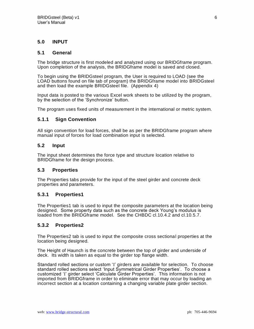
5.0 INPUT
5.1 General The bridge structure is first modeled and analyzed using our BRIDGframe program. Upon completion of the analysis, the BRIDGframe model is saved and closed. To begin using the BRIDGsteel program, the User is required to LOAD (see the LOAD buttons found on file tab of program) the BRIDGframe model into BRIDGsteel and then load the example BRIDGsteel file. (Appendix 4) Input data is posted to the various Excel work sheets to be utilized by the program, by the selection of the ‘Synchronize’ button. The program uses fixed units of measurement in the international or metric system.
5.1.1 Sign Convention
All sign convention for load forces, shall be as per the BRIDGframe program where manual input of forces for load combination input is selected.
5.2 Input The input sheet determines the force type and structure location relative to BRIDGframe for the design process.
5.3 Properties The Properties tabs provide for the input of the steel girder and concrete deck properties and parameters.
5.3.1 Properties1
The Properties1 tab is used to input the composite parameters at the location being designed. Some property data such as the concrete deck Young’s modulus is loaded from the BRIDGframe model. See the CHBDC cl.10.4.2 and cl.10.5.7.
5.3.2 Properties2
The Properties2 tab is used to input the composite cross sectional properties at the location being designed. The Height of Haunch is the concrete between the top of girder and underside of deck. Its width is taken as equal to the girder top flange width. Standard rolled sections or custom ‘I’ girders are available for selection. To choose standard rolled sections select ‘Input Symmetrical Girder Properties’. To choose a customized ‘I’ girder select ‘Calculate Girder Properties’. This information is not imported from BRIDGframe in order to eliminate error that may occur by loading an incorrect section at a location containing a changing variable plate girder section.

BRIDGsteel (Beta) v1 7 User’s Manual
web: www.bridge-structural.com ph: 705-446-9694
The User must consider changes to the girder such as drill holes through the flanges or web which influence the girder geometric properties. This tab also contains input required to establish the resistance of the girder during the construction stage or the naked girder. The unsupported length of the girder is typically that of the diaphragm spacing. The User may choose to enter factored moments within the girder, however this input is optional. If these factored moments
are left blank, the program defaults the variable ‘2’ to 1. The Factored Moments at Girder Left and Right End is positive for clockwise rotation and negative for counterclockwise rotation.
5.3.3 Properties3
The Properties3 tab is used to establish the effective contributing deck width for positive and negative moment regions as per cl.5.8.1. A ‘Calculate’ button has been provided to assist the User.
5.4 Loads The User has the option of completing the design using load cases automatically imported from BRIDGframe or by manually generating load combinations using BRIDGframe and inputting the results into BRIDGsteel.
5.4.1 Loads 1
The Loads1 tab is used to input construction load factors and to select whether to perform the composite design using individual load cases or to use User established load combination results. Loads 1 also includes the load factors for dead and superimposed dead loads if load case input is selected. Design using Load Cases is automated to load all individual loadings from BRIDGframe and develope the necessary limit state combinations. Input is simplified although there is more output involved. Design using load combinations requires the User to spend more time obtaining BRIDGsteel input values from BRIDGframe and has a greater possibility of error if the User does not generate the governing load combination condition. It does however, result in less BRIDGsteel output. If the User chooses to design using load cases, the loads that will be imported into BRIDGsteel from BRIDGframe will be that of the x/L location selected on the Input tab. If the User chooses to design using load combinations, the x/L location selected on the Input tab will not be relevant and the User must manually enter the required load combination data.
5.4.2 Loads 2
The Loads2 tab is used to input the remaining load case factors for the Live (truck), all ‘K’, wind, settlement and soil force effects when designing using load cases. Loads 2 will also be utilized if load combination is selected on the Loads 1 tab. For design using load combinations, ‘Remaining Loads’ is User defined. It may mean an individual load case or the summation of multiple load case results.

BRIDGsteel (Beta) v1 8 User’s Manual
web: www.bridge-structural.com ph: 705-446-9694
Remaining Load would mean any load or loads that are not being accounted for. For SLS, dead and sidl is already being accounted for and would not establish part of the Remaining Load. For ULS, dead and live is already being accounted for and would therefore not establish part of the Remaining Load. For Soil with inclusive temperature effects, BRIDGsteel will automatically use the maximum or minimum load factor that causes the maximum load effect at the location being designed.

BRIDGsteel (Beta) v1 9 User’s Manual
web: www.bridge-structural.com ph: 705-446-9694
6.0 DESIGN ULS-N 1&2 and ULS-N 3&4 designs are relative to the x/L location as selected on the INPUT tab. ULS-N 1&2 (2) and ULS-N 3&4 (2) is design by using load combination values manually entered by the User and is not related to the x/L location. The Design tabs contain additional input requirements for moment and shear design calculations and vibration. Design in negative moment regions is assumed to contain shear connectors.
6.1 Design 1 ULS: The Design 1 tab is used to input optional compression and tension design when doing moment design. This input was included if a User has chosen to design to cl.10.9.4. Although integral abutment or rigid frame bridge structures generate axial forces in the superstructure, generally these forces are not significant enough to utilize this input into the program. FLS: The User shall select the applicable Detail Category in accordance with Table 10.4, Table 10.7 and Figure 10.6. For example, at connection plates the detail category may be B at the bottom of bottom flange and top of top flange, and the detail category may be C1 at the top of bottom flange and bottom of top flange, where the welding takes place. SLS2: Vibration as per cl.3.4.4 is also included on the Design 1 tab but is only visible when designing for Positive Bending Moments.
6.2 Design 2 The Design 2 tab contains additional input to complete the Shear design. If Shear was not selected on the Input tab, this page will appear blank. Connector material property is as per cl.10.4.7.

BRIDGsteel (Beta) v1 10 User’s Manual
web: www.bridge-structural.com ph: 705-446-9694
7.0 OUTPUT
7.1 General The amount of output results is dependent on the number of x/L locations designed for, and whether the User has chosen to design using load cases or load combinations. References to the CHBDC are provided on each output sheet to assist the User in verifying the application.
7.2 Results The force type and location is specified on the input tab. Only the results relative to the input tab selection will be visible at any one time.
7.2.1 Info
The Info work sheet contains the general data required to be utilized by most of the design sheets. Much of this information is imported from the BRIDGframe file and much of it will have been previously entered in the Excel file.
7.2.2 Mr STD, Mr CUST, and Vr
The naked girder moment resistance for class 1, 2 and 3 sections, and the naked girder shear resistance are provided as per cl.10.10.2.3, 10.10.2.4, and 10.10.5 respectively.
7.2.3 SECT-P and SECT-N
The positive moment region section properties are calculated using the effective width of deck “ew” as per cl.5.8.2. Deck reinforcing is not included in the positive moment region section property calculations. The negative moment region section properties are calculated using the area of longitudinal deck reinforcing within the effective width of deck “ew” as per cl.5.8.1. The section properties will consist of the steel girder and deck reinforcing only; no deck concrete will be used to establish the negative moment region properties. For both SECT-P and SECT-N, the section properties are calculated for both the exterior and interior girder.
7.2.4 CONSTR
The program checks the capacity of the girder for moment and shear during the construction stage using data imported from BRIDGframe. The data imported from BRIDGframe is relative to the x/L location selected on the INPUT tab.

BRIDGsteel (Beta) v1 11 User’s Manual
web: www.bridge-structural.com ph: 705-446-9694
7.2.5 LIVE, DEAD-SIDL, K, SOIL, WIND, DSETT
LIVE: The live load used in BRIDGsteel is relative to the x/L location selected on the INPUT tab. The live load amplification factors for distribution of forces to the exterior and interior girder are imported from BRIDGframe and loaded into the INFO work sheet to be utilized by the live load calculations. ULS, SLS and FLS values are established for moments and axial loads (live load shear is performed on the shear sheets). This sheet is not applicable if the User chooses to design using load combinations. DEAD-SIDL, K, SOIL, WIND, DSETT: The primary function of these sheets are to accept the force values imported from BRIDGframe and determine the forces per girder for the different limit state conditions as applicable. Some of the load cases will include the stress results at critical section locations. The distribution of these forces is fixed as equal amongst the girders.
7.2.6 DTEMP, DSHR
These conditions impart an axial force equal in magnitude but opposite in direction between the girder and deck. The Axial force reported in BRIDGframe comprises of three components. The first being that in the entire superstructure due to frame action, the second being that in the girder due to the Driving force of the deck shrinkage, and the third being that of the deck due to being restrained by the composite girder. The Axial force from frame action is added to the individual axial forces in the girder and deck to get the total axial in each one of these two components. The driving axial forces are considered at SLS and FLS only.
7.2.7 VIBR
Vibration limitations are calculated as per cl.3.4.4. Imported BRIDGframe values for calculating the superstructure vibration are relative to the x/L location selected on the INPUT tab.
7.2.8 SLS-P, SLS-N, SLS-P (2), SLS-N (2)
SLS-P, SLS-N: SLS-P provides a stress check at the composite section properties critical locations in the positive bending moment region. SLS-N provides a stress check at the composite section properties critical locations in the negative bending moment region. Some loads are considered “Transitory Loads” and are isolated during this design process. Where a transitory load creates a net stress that decreases the total stress effect, that load case is removed from the design. Note; as this does not form part of the CHBDC, the result is reported as a percentage of the steel yield strength for the purpose of providing information to the User only, and not a condition to be met. The purpose of providing the stress design using transitory loads was to primarily provide the User with an indication of the total effects from a frame structure. A stress check as per cl.10.11.4 is provided but has been modified to include axial forces that occur from primarily a frame structure. SLS-P (2), SLS-N (2): these sheets provide a stress check as per cl.10.11.4 if the User has chosen to design using load combinations rather than by load cases. The results in accordance with cl.10.11.4 have been modified to include axial forces from primarily a frame structure.

BRIDGsteel (Beta) v1 12 User’s Manual
web: www.bridge-structural.com ph: 705-446-9694
7.2.9 ULS-P 1&2, ULS-P 3&4, ULS-P 1&2 (2), ULS –P 3&4 (2)
ULS-P 1&2 and ULS-P 3&4 designs are relative to the x/L location as selected on the INPUT tab. ULS-P 1&2 (2) and ULS-P 3&4 (2) is design by using load combination values manually entered by the User and is unrelated to the x/L location. ULS-P 1&2 and ULS-P3&4: provides a positive moment strength design for the composite exterior girder and interior girder design strip of a class 1 and 2 section or a class 3 and 4 section as per cl.10.11.5.2 or 10.11.6.2 respectively, using imported load cases from BRIDGframe. ULS-P 1&2 (2) and ULS-P 3&4 (2): provides positive moment strength design for the composite exterior girder and interior girder design strip of a class 1 and 2 section or a class 3 section as per cl.10.11.5.2 or 10.11.6.2 respectively, using load combination results manually input by the User.
7.2.10 ULS-N 1&2, ULS-N 3&4, ULS-N 1&2 (2), ULS-N 3&4 (2)
ULS-N 1&2 and ULS-N 3&4 designs are relative to the x/L location as selected on the INPUT tab. ULS-N 1&2 (2) and ULS-N 3&4 (2) is design by using load combination values manually entered by the User and is unrelated to the x/L location. ULS-N 1&2 and ULS-N 3&4: provides a negative moment strength design for the composite exterior girder and interior girder design strip of a class 1 and 2 section or a class 3 section as per cl.10.11.5.3 or 10.11.6.3 respectively, using imported load cases from BRIDGframe. ULS-N 1&2 (2) and ULS-N 3&4 (2): provides a negative moment strength design for the composite exterior girder and interior girder design strip of a class 1 and 2 section or a class 3 section as per cl.10.11.5.3 or 10.11.6.3 respectively, using load combination results manually input by the User.
7.2.11 FLS-P, FLS-N
Imported BRIDGframe values for FLS-P and FLS-N are relative to the x/L location selected on the INPUT tab FLS-P, FLS-N: provides a live load stress range fatigue design for the composite exterior girder and interior girder design strip as per cl.10.17 using the imported live load case from the BRIDGframe LIVE2 work sheet. Fatigue design is not done when using the load combinations option on the Loads 1 tab.
7.2.12 SHEAR
The Shear work sheet provides design for the shear capacity of the steel girder section and the shear connectors or studs. The shear capacity of the girder is a strength design check at ULS as per cl.10.10.5.2 and utilizes maximum moment and corresponding shear or maximum shear and corresponding moment. The shear connector design is that of ULS and FLS as per cl.10.11.8.3 and 10.17 respectively.

BRIDGsteel (Beta) v1 13 User’s Manual
web: www.bridge-structural.com ph: 705-446-9694
r*Ar*fy is not used to calculate ‘P’ for the positive moment region and is therefore set to equal 0 (zero). Imported BRIDGframe values for performing the shear design calculations are relative to the x/L location selected on the INPUT tab.
7.2.13 SHEAR (2) and Vf Mf (2)
Shear (2): The Shear (2) work sheet is for design using load combinations manually input by the User and provides shear connector design to that of ULS and FLS as per cl.10.11.8.3 and 10.17 respectively.
r*Ar*fy is not used to calculate ‘P’ for the positive moment region and is therefore set to equal 0 (zero). Vf Mf (2): ): The Vf Mf (2) work sheet is for design using load combinations manually input by the User and provides design for the shear capacity of the steel girder section. The shear capacity of the girder is a strength design check at ULS as per cl.10.10.5.2 and utilizes maximum moment and corresponding shear or maximum shear and corresponding moment.

BRIDGsteel (Beta) v1 14 User’s Manual
web: www.bridge-structural.com ph: 705-446-9694
8.0 Printing Printing of Excel sheets is done by selection of each work sheet as found on the program ‘Print’ sheet. Printing may also be done manually by selecting the data of interest and designating it for printing using the Print Area command. To print the program input sheets (tab dialogue pages), the User may: i) press ‘Ctrl,’ ‘Alt’ and ‘Prt Sc’ simultaneously when on the sheet of preference to print; then in Microsoft Word place the cursor where the top left corner of the saved print screen will be dropped and press ‘Ctrl’ and ‘V’ simultaneously.

BRIDGsteel (Beta) v1 15 User’s Manual
web: www.bridge-structural.com ph: 705-446-9694
9.0 Troubleshooting If the User does not Load a compatible Excel file, an Error or Error message will appear. Probable Resolution: Load a compatible Excel BRIDGframe and BRIDGsteel spreadsheets that was received with the program. The program fails during registration confirmation. Probable Resolution: The firewall may be blocking communication with our website. Configure the firewall to allow communication with www.bridge-structural.com. Confirm there is an internet connection. Further configuration of the firewall may be required to allow BRIDGsteel.exe and BRIDGsteelUpdater.exe to access the internet. If the appearance of the program is not as per the screen prints shown in the Appendix 4 Input Examples, the issue may be with the monitor settings. Right click on the Desk Top, select Properties/ Settings/ Advanced/ General Tab/ the DPI setting should be that of Normal Setting. The program fails and gives an error message when trying to analyse. Probable Resolution: Macros have not been allowed to run. Program requires Excel 2007 or later (2007 not recommended). Excel 2007 and later require special attention to have Trust settings configured to allow macros within BRIDGframe to run. Computer Regional Settings must be set for English. See also www.support.microsoft.com/kb/320369 Error Number 5 Access to the path ‘C:\ProgramFiles(x86)\Simplified Bridge Solutions\BRIDGframe\SBS.ini’ is denied. Probable Resolution: writing permission is required to C:\ProgramFiles\Simplified Bridge Solutions\BRIDGframe, or location program is saved in.

BRIDGsteel (Beta) v1 16 User’s Manual
web: www.bridge-structural.com ph: 705-446-9694
10.0 Limitations Stiffeners do not form part of this program. Longitudinal shear does not form part of this program. Steel girder shapes other than “I” girders are not fully supported. Horizontal curvature of bridge is limited to A5.1.3.2. Supported load cases are those generated in BRIDGframe. Distortion does not form part of this program. Splices and connections do not form part of this program. Openings in girder flanges and/or web, or changes in the deck slab are not part of the input of this program and therefore require User generated data input. Note: above limitations may be removed in future updates.

BRIDGsteel (Beta) v1 17 User’s Manual
web: www.bridge-structural.com ph: 705-446-9694
APPENDIX 1 - PROGRAM FEATURES BRIDGsteel composite steel girder design software
conformance with the Canadian Highway Bridge Design Code CAN/CSA-S6-14 simple and minimal tabular input automatic importing of data from BRIDGframe analysis program design of positive and negative moment regions, shear / shear connectors, and
vibration SLS, ULS and FLS design naked girder and composite girder design drop-down menu’s of standard steel sections customized plate girder building tool print tab makes printing worksheets simple print results are as per they appear on the worksheets
output is very clearly defined
output is in Microsoft Excel, making it very accessible for viewing and generating graphical output

BRIDGsteel (Beta) v1 18 User’s Manual
web: www.bridge-structural.com ph: 705-446-9694
APPENDIX 2 - SOFTWARE LICENSING AGREEMENT AND INSTALLATION BRIDGsteel Software Licensing Agreement By installing the BRIDGsteel Software (which consists of software, documentation and other items; hereafter: “Software”) created by Simplified Bridge Solutions Ltd., you agree to be bound by the terms and conditions of this License Agreement. As used in this License Agreement, “You” shall mean the individual us ing or installing the Software together with any individual or entity, including but not limited to your employer, on whose behalf you are acting in using or installing the Software. You shall be the “licensee” under this License Agreement. This License Agreement constitutes the complete agreement between you and Simplified Bridge Solutions Ltd. No amendment or modification may be made to this Agreement except in form of writing signed by you and Simplified Bridge Solutions Ltd. If you do not agree to any of the terms and conditions of the Agreement, you must discontinue use of the Software immediately.
1. License Grant In consideration for the license fee paid, and other good and valuable consideration, Simplified Bridge Solutions Ltd. grants to you only, the Licensee, the non-exclusive, non-transferable right to use the Software in accordance with the license you purchase. If you are using this product for your employer, this Agreement also includes your employer. You may only use the Analysis functionality of the Software on the computer for which the Software is licensed. The software may be distributed freely to facilitate the printing of analysis output.
2. Copyright The Software as developed by Simplified Bridge Solutions Ltd. and the accompanying materials are copyrighted and contain proprietary information. Unauthorized modification of the Software is expressly forbidden. Unauthorized copying of accompanying materials even if merged, or included with other software, is expressly forbidden. You may be held legally responsible for any infringement of intellectual property rights that is caused or encouraged by your failure to abide by the terms of this Agreement. Simplified Bridge Solutions Ltd. reserves all rights not specifically granted to Licensee. Simplified Bridge Solutions Ltd. warrants that Simplified Bridge Solutions Ltd. is the sole owner of all copyrights or other applicable intellectual property rights in and to the Software unless otherwise indicated in the documentation for the Software. Simplified Bridge Solutions Ltd. shall defend and hold Licensee harmless from any third party claims for intellectual property infringement for properly licensed Software provided by Simplified Bridge Solutions Ltd. You do not own the Software. The Software and documentation are licensed, not sold to you. You may not disassemble, decompose or otherwise reverse engineer the Software. You must not alter the Software. You may freely distribute the software to others. Others to print analysis output may use distributed copies; the analysis functionality will be disabled until a license is purchased.

BRIDGsteel (Beta) v1 19 User’s Manual
web: www.bridge-structural.com ph: 705-446-9694
3. Warranty and Risks Although extensive efforts have been made to assure that the Software is date compliant, correct, reliable and technically accurate, the Software is licensed to you as is and without warranties. You, your organization, and all users of the Software, assume all risks when using it. In any case, the entire liability under any provision of this Agreement shall be limited to the greater of the amount actually paid by You for the Software or the equivalent of the amount paid by You for the Software.
4. Support, Upgrades and Service Releases Simplified Bridge Solutions Ltd. shall offer free technical support that does not fall under the scope of providing engineering services, and product upgrades for the licensed term after purchasing the product. The product license expires at the term end; therefore, you must pay the annual maintenance fee in order to receive a renewal license and ongoing support and product upgrades.
5. Termination This Agreement is effective until terminated. This Agreement will terminate automatically without notice from Simplified Bridge Solutions Ltd. if you fail to comply with any provision contained herein or if the funds paid for the license are refunded or are not received. Upon termination, you must destroy the Software, and all cop ies of the Software, in part and in whole, including modified copies if any.
6. Non-Waiver The failure by either party at any time to enforce any of the provisions of this License Agreement or any right or remedy available hereunder or at law or in equity, or to exercise any option herein provided, shall not constitute a waiver of such provision, right, remedy, or option or in any way affect the validity of this License Agreement. The waiver of any default by either party shall not be deemed a continuing waiver, but shall apply solely to the instance to which such waiver is directed.

BRIDGsteel (Beta) v1 20 User’s Manual
web: www.bridge-structural.com ph: 705-446-9694
BRIDGsteel Installation Design parameters and calculation results for composite girder designs are stored in Excel workbooks, one workbook per design. BRIDGsteel is a dialog that provides the User Interface to these Excel workbooks. An example workbook is required as the starting point for your first new analysis. Later analysis may utilize this workbook or other saved workbooks generated from the original Excel file. All files are available for download directly from our website. Certain advanced features are disabled until the application is registered. BRIDGsteel will run in Demo mode only, if User is not licensed.
BRIDGsteel (Beta) v1 21 User’s Manual
web: www.bridge-structural.com ph: 705-446-9694
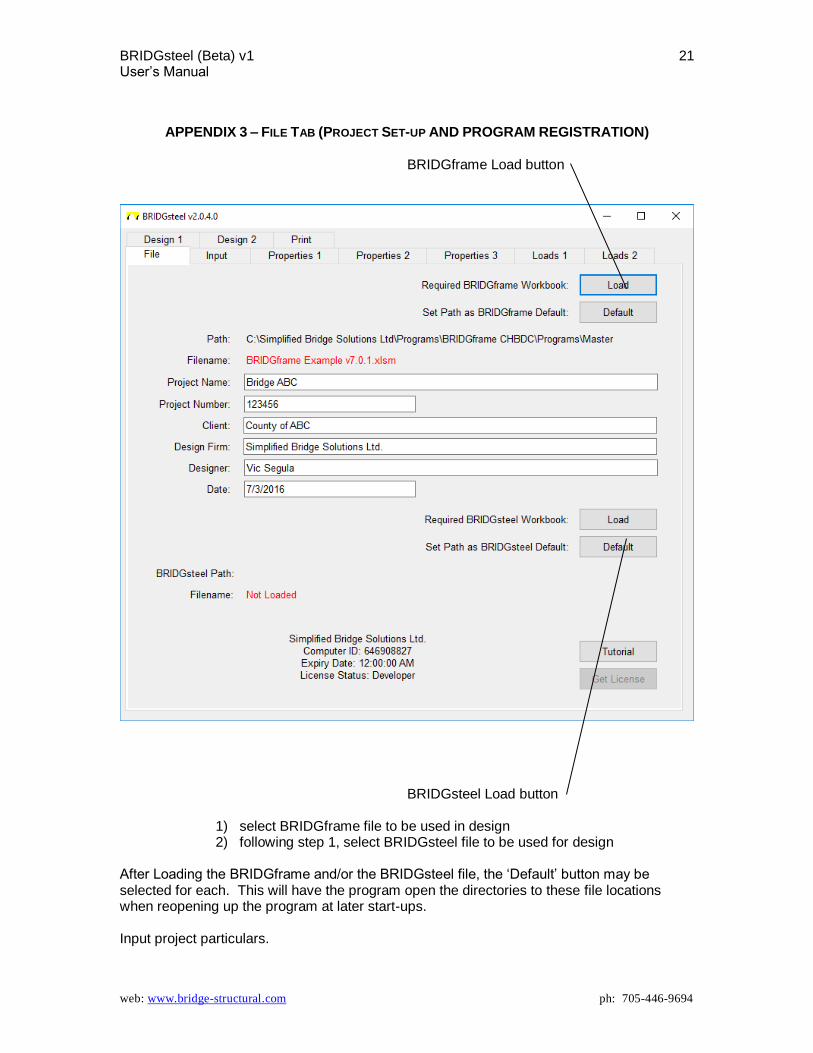
APPENDIX 3 – FILE TAB (PROJECT SET-UP AND PROGRAM REGISTRATION) BRIDGframe Load button
BRIDGsteel Load button
1) select BRIDGframe file to be used in design 2) following step 1, select BRIDGsteel file to be used for design
After Loading the BRIDGframe and/or the BRIDGsteel file, the ‘Default’ button may be selected for each. This will have the program open the directories to these file locations when reopening up the program at later start-ups. Input project particulars.
BRIDGsteel (Beta) v1 22 User’s Manual
web: www.bridge-structural.com ph: 705-446-9694
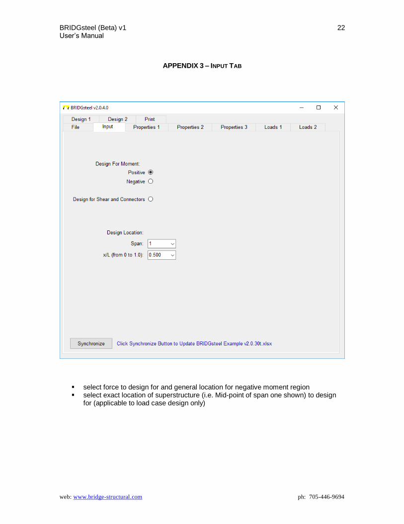
APPENDIX 3 – INPUT TAB
select force to design for and general location for negative moment region select exact location of superstructure (i.e. Mid-point of span one shown) to design
for (applicable to load case design only)

BRIDGsteel (Beta) v1 23 User’s Manual
web: www.bridge-structural.com ph: 705-446-9694
APPENDIX 3 – PROPERTIES 1 TAB
Check the available boxes if wanting to use the same properties as that of the BRIDGframe file, the click Import
BRIDGsteel (Beta) v1 24 User’s Manual
web: www.bridge-structural.com ph: 705-446-9694
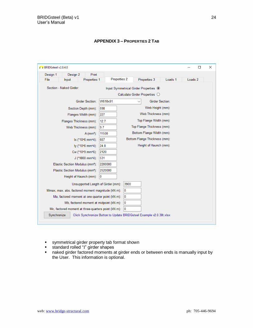
APPENDIX 3 – PROPERTIES 2 TAB
symmetrical girder property tab format shown standard rolled “I” girder shapes naked girder factored moments at girder ends or between ends is manually input by
the User. This information is optional.
BRIDGsteel (Beta) v1 25 User’s Manual
web: www.bridge-structural.com ph: 705-446-9694
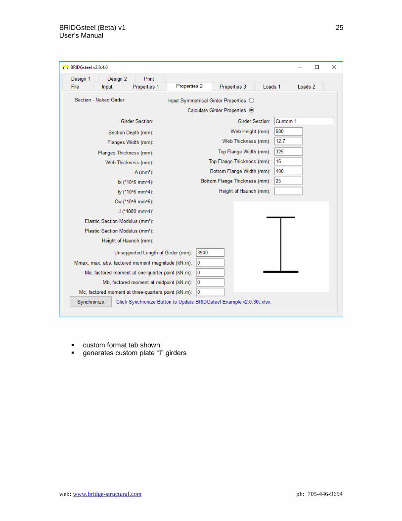
custom format tab shown generates custom plate “I” girders

BRIDGsteel (Beta) v1 26 User’s Manual
web: www.bridge-structural.com ph: 705-446-9694
APPENDIX 3 – PROPERTIES 3 TAB
effective deck width of composite girder design strip may be manually entered or automatically calculated
BRIDGsteel (Beta) v1 27 User’s Manual
web: www.bridge-structural.com ph: 705-446-9694
APPENDIX 3 – LOADS 1 TAB
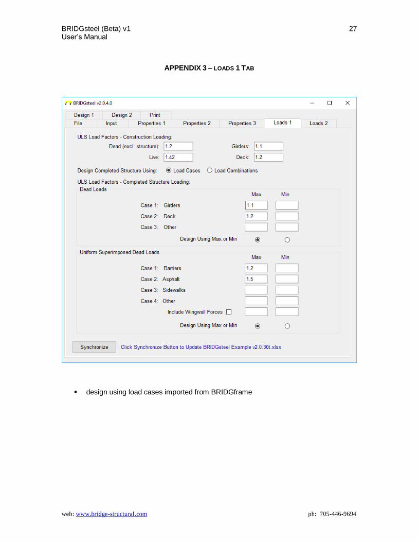
design using load cases imported from BRIDGframe
BRIDGsteel (Beta) v1 28 User’s Manual
web: www.bridge-structural.com ph: 705-446-9694
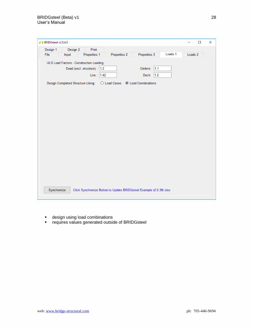
design using load combinations requires values generated outside of BRIDGsteel

BRIDGsteel (Beta) v1 29 User’s Manual
web: www.bridge-structural.com ph: 705-446-9694
APPENDIX 3 – LOADS 2 TAB
design using load cases imported from BRIDGframe
BRIDGsteel (Beta) v1 30 User’s Manual
web: www.bridge-structural.com ph: 705-446-9694
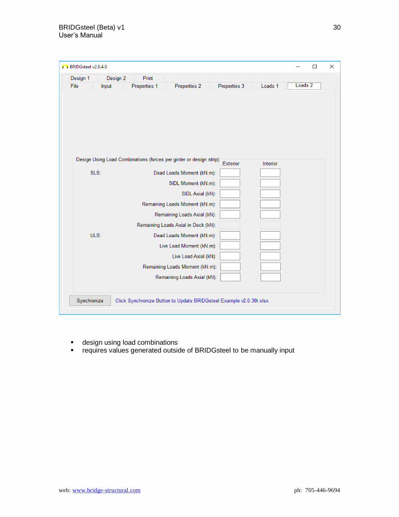
design using load combinations requires values generated outside of BRIDGsteel to be manually input

BRIDGsteel (Beta) v1 31 User’s Manual
web: www.bridge-structural.com ph: 705-446-9694
APPENDIX 4 – DESIGN 1 TAB
If User chooses to include compression and tension in ULS design, required data is to be provided by and manually entered by the User.
Note: tension & compression resistance is dependant on the amount of force that can actually be developed within the member.

BRIDGsteel (Beta) v1 32 User’s Manual
web: www.bridge-structural.com ph: 705-446-9694
APPENDIX 5 – DESIGN 2 TAB
if design for moments was selected on the INPUT tab, this sheet appears as blank for class 1 & 2 sections

BRIDGsteel (Beta) v1 33 User’s Manual
web: www.bridge-structural.com ph: 705-446-9694
if design for moments was selected on the INPUT tab and the class of section is 4 for custom plate girders, this sheet provides data and input for the reduction factor relative to the stiffeners that may be required

BRIDGsteel (Beta) v1 34 User’s Manual
web: www.bridge-structural.com ph: 705-446-9694
for shear design as selected on the INPUT tab ‘Synchronize All’ may be used to synchronize all at once rather than re-synchronizing
each sheet where applicable. More specifically, it allows the User to make one change in the Input on one of the tabs and go straight to Synchronize All.
BRIDGsteel (Beta) v1 35 User’s Manual
web: www.bridge-structural.com ph: 705-446-9694
APPENDIX 6 – PRINT TAB
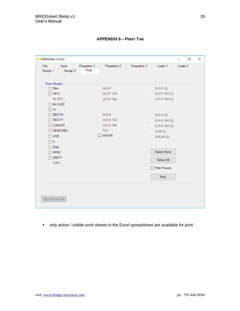
only active / visible work sheets in the Excel spreadsheet are available for print