bridge protocols ieee 802.1 spanning tree learning bridge protocol (stp)
DESCRIPTION
Common Protocols and Interfaces - Part 2. Bridge Protocols IEEE 802.1 Spanning Tree Learning Bridge Protocol (STP) IEEE Standard 802.1 is a bridging protocol STP defines forwarding table operation for bridges that span multiple networks - PowerPoint PPT PresentationTRANSCRIPT
Bridge ProtocolsIEEE 802.1 Spanning Tree Learning Bridge
Protocol (STP) IEEE Standard 802.1 is a bridging protocol STP defines forwarding table operation for bridges that
span multiple networks It provides the function of frame (packet) forwarding
table It is dynamic and corrects forwarding problems such as
forwarding loops or unavailable circuit paths. Each data frame passing through a bridge is examined
and forwarded on through a process called filtering
IEEE 802.1 Spanning Tree Learning Bridge Protocol (STP) (Continue…)
STP is a true bridging protocol and is inefficient and disadvantageous when used as a large networking protocol.
STP is better utilized when the network is made up of many point-to-point circuits.
STP elimination of loop paths ties up expensive leased-line resources.
Spanning tree table building after network failures takes considerable time and introduces long user delays.
IBM Source Routing Protocol (SRP) The IBM SRP allows LAN workstations to specify their
routing for each packet transmitted Each packet transmitted by a workstation on the LAN to
the bridge contains a complete set of routing information for the bridge to route upon
The information for source routing to perform its function is contained in the routing information field within the MAC sublayer frame
Refer to Figure 8.1 (p. 281) IBM’s Token Ring implementation of source routing has
a seven-hop count maximum
Source Route Transparent (SRT) Bridging IEEE SRT marries the IEEE STP and the SRP into one bit-
selective bridging protocol Many bridges achieve forwarding rates of over 14,500
frames per second sustained over a long period of time using this technique.
SRP has more overhead than SRT, but the processing is reduced for each bridge it traverses
SRT can also allow SNA source routing into Ethernet TCP/IP networks and DECnet networks
Source Routing Extensions Many vendors such as Bay Networks and Cisco Systems
have implemented extensions to the SRB protocol. These routers, while providing bridging capability, can
transit bridged traffic across an entire WAN composed of multiple routers, and still the entire network will only count as a single hop (eliminating the seven-hop count restriction)
Routing tables are built dynamically through use of the source route explorer packets
This method improves reliability of transmission, eliminates the hop count restriction, and can decreases response time across the network.
Routing Protocols Routers perform both routing and bridging functions.
However, both methods require that the router performs address translation.
There are multiple routing protocols that build forwarding tables using different metrics
Routers use a series of algorithms to perform the task of routing, along with dynamic routing tables to manage this routing
Almost all routers support bridging protocols, as it is preferable to perform translation bridging with a router as opposed to encapsulation bridging with a bridge
Routing Protocols Defined Routing, or gateway protocols, provide router-to-router
communications between like routers using routing tables.
Communications can take place between autonomous systems and within autonomous systems
EGP, IGRP, RIP, BGP, OSFP, IS-IS Serial line protocols provide communications over serial
or dial-up links between unlike routers
HDLC, PPP, SLIP Gateway protocols pass the routing table information and
“keep alive” packets, and the serial line protocol passes the true user data
Routing Protocols Defined (Continue…) Routers need to determine the best way to reach an
address through a network of nodes. Routing algorithms generally exchange information
about a topology based upon in one or two generic methods Distance vector: algorithms use neighbor nodes to
periodically exchange vectors of the distance to every destination in the network
Link state: algorithms have each router learn the entire link state topology of the entire network. This is currently done by flooding only changes to the link state topology through the network
Routing Protocols Defined (Continue…) The link state approach is more complex, but converges
much more rapidly Convergence is the rate at which a network goes from
an unstable state to a stable state
Distance Vector Routing Protocols It is used by the Internet’s Routing Information Protocol (RIP). A key advantage of the distance vector is its simplicity A key disadvantage is that the topology information message
grows larger with the network and the time for it to propagate through the network increases as the network grows IP RIP automatically summarizes at the edges of a class
(A,B,C) network OSFP can be configured to summarize on more arbitrary
area boundaries IPX RIP doesn’t do any summarization at all
Refer to Figure 8.2 (p. 284)
Distance Vector Routing Protocols (Continue…)
RIP Operates in a connectionless mode at the application
layer, interfacing with transport layer protocols through UDP
Its decision for routing is based upon hop count only (no length of the hop)
This can cause problems when a higher-bandwidth path is available and desirable for transport
Refer to Figure 8.3 (p. 285) RIP has a hop-count restriction of 16 hops, and is
prone to routing loops if misconfigured
Distance Vector Routing Protocols (Continue…) IGRP
Superior than RIP because it understands bandwidth limitations between hops, as well as time delays
It is tunable to make it faster if desired It doubles the transmit time of information between
nodes, amplifying the opportunity for a convergence problem
EGP and BGP Exterior routing protocols used between separately
administered networks ISPs use BGP to share routing information between their
networks
Link State Routing Protocols The link state advertisement method was designed to
address the scalability issues of the distance vector method. Routing tables are exchanged with neighbors, but every
device on the network must be at least one other device’s neighbor
Link state updates are sent using 64-byte packets (depending on the specific protocol) in a multicast mode, and require acknowledgments
This protocol will also notify users if their address is unreachable
This method is more memory intensive for the router, and requires large amounts of buffers and memory space
Link State Routing Protocols (Continue..) There are three major implementations of link state
routing protocols on the market: Open Shortest Path First (OSPF):
Based upon shortest path, bandwidth available, cost in dollars, congestion, interface costs, and time delay
All costs for links are designated on the outbound router port
Supports point-to-point, broadcast, and NonBroadcast MultiAccess (NBMA).
OSFP is only useful with TCP/IP networks
Link State Routing Protocols (Continue..) Intermediate System to Intermediate System (IS-IS)
Used to route between network nodesAn extension of IS-IS (Dual IS-IS) can support both
OSI and TCP/IP networks simultaneouslyHowever, OSPF provides a wider range of interface
costs than IS-IS Novell’s NLSP
Proprietary Novell protocol Refer to Table 8.1 (p. 297)
Network and Transport Layer Protocols- The Internet Protocol Suite (TCP/IP)
Structure of TCP/IP TCP provides a reliable, sequenced delivery fo data to
applications. UDP only provides an unacknowledged datagram
capability TCP also provides adaptive flow control, segmentation,
and reassembly, and prioritized data flows. Refer to Figure 8.4 (p. 289) A number of applications interface to TCP and UDP: FTP,
TELNET, SNMP, TFTP, RPC, NFS
IP Packet Formats Refer to Figure 8.5 (p. 290)
Internet Protocol (IP) Addressing Uses 32-bit IP addresses as a global addressing scheme IP addresses are grouped into classes A, B, C Refer to Figure 8.6 (p. 291) Internet addresses are assigned and managed by Internet
Assigned Numbers Authority (IANA) IP works with TCP for end-to-end reliable transmission of
data across the network TCP will control the amount of unacknowledged data in
transit by reducing either the window size or the segment size
TCP/IP Functions IP provides a connectionless datagram delivery service
to the transport layer TCP provides an end-to-end reliable delivery, error
control, retransmission, or flow control Refer to Figure 8.7 (p. 292) IP provides the means for devices to discover the
topology of the network, as well as to detect changes of state in nodes, links, and hosts
Refer to Figure 8.8 (p 294)
Traffic and Congestion Control Aspects of TCP/IP
TCP flow control uses a sliding window flow-control protocol, like X.25
However, the window is of a variable size, instead of the fixed window size used by X.25
Refer to Figure 8.9 (p. 294)
Service Aspects of TCP/IP TCP/IP implementations typically constitute a router, TCP/IP
workstation and server software, and network management. Operation of IP over a number of network, data link, and
physical layer services is defined.
IP Next Generation (IPng)-IPv6 Expands the address size from 32 to 128 bits Simple dynamic auto-configuration capability Easier multicast routing with addition of “scope” field Anycast feature-send packet to anycast address and it is delivered
to one of the nodes which allows nodal routing control Capability to define quality of service to a traffic flow added Reduction of overhead-some header fields are optional More flexible protocol design for future enhancements Authentication, data integrity, and confidentiality options Easy transition and interoperability with IPv4 Support for all IPv4 routing algorithms (e.g., OSPF, RIP, etc)
Legacy SNA SNA still maintains the predominant corporate
mainframe architecture, accounting for over 50 percent of world-wide data communications networks.
Traditional SNA architecture is master-slave and thus hierarchical in nature.
SNA is now moving toward a more distributed, peer-to-peer architecture called Advanced Peer-to-Peer Networking (APPN)
Building Blocks of Traditional SNA Host Processor: is also called a Central Processing Unit
(CPU). Devices include the IBM 3090, 4381, and 9370
Cluster Controller or Terminal Controllers: control a cluster of 8 to 32 typically coax-attached terminals and printers.
Refer to Figure 8.11 (p. 298) Refer to Figure 8.12 (p. 298) Establishment Controller Units: or ECUs are a form of
cluster controllers that can act as a gateway for mainframe connectivity to a Token Ring or Ethernet LAN for VTAM access.
Refer to Figure 8.13 (p. 299)
Communications Controllers (CCs) or Front-End Processors (FEPs): provide access for connecting cluster controllers to a mainframe through a Network Control Protocol (NCP).
FEPs perform front-end processing for the host, route data within the SAN protocol stack between CCs, and can act as concentrators to multiple controllers, terminals, and other communication devices.
Refer to Figure 8.14 (p. 300) Refer to Figure 8.14 (p. 301) Refer to Figure 8.15 (p. 301)
Interconnect Controllers: such as the IBM 3172 provide direct connection for a mainframe to an Ethernet, Token Ring, or FDDI LAN user access to VTAM
Refer to Figure 8.17 (p. 302) IBM Minicomputers: such as the AS400 and System/36
form the cornerstone of most APPN networks. Communications Access Methods: include both
ACF/VTAM and ACF/TCAM Operating Systems (OS) include MVS/XA, MVS/ESA,
DOS/VSE, and OS/2 Host Applications: include CICS,IMS/DC, and TSO
Network Addressable Units - PUs, LUs, and Domains
Synchronization of communications, resource management, and control of the network are managed by Network Addressable Units (NAUs) LU (logical unit) - are “sessions” between end-user access ports
on the network PU (physical unit) - manages the LU SSCP (systems services control point) - defines a single point
for domain control
A network device PU, LU, SSCP is combined to form the network addressable unit (NAU), which forms the network address for a given device.
Network Addressable Units - PUs, LUs, and Domains (Continue…)
Each device in the network is labeled a node An area controlled by one host is called the domain The primary communications protocol is SDLC Refer to Figure 8.18 (p. 304)
SNA Legacy Software Communications Virtual Telecommunications Access Method (VTAM) is the
software that resides in the host computer and communicates with the “dumb” terminals attached to the 3174
The FEP runs a software called Network Control Program (NCP)
IBM SNA/SDLC Migration to LAN/WAN Internetworking
One of the advantages of placing SNA traffic over a WAN is that broadcast packets and unnecessary polling overhead can be eliminated, similar to a more dynamic method of filtering
There are many methods of tying SNA networks into the non-SNA WAN environment
SNA over X.25 - NPSI IBM offers software and hardware called the Network
Control Protocol (NCP) Packet Switching Interface (NPSI) as one option for encapsulating SDLC traffic for transport across the WAN
NPSI encapsulates SNA traffic into X.25 packets Refer to Figure 8.19 (p. 305)
QLLC Conversion - SNA over X.25 The requirement for NPSI can be eliminated by
attaching a Token Ring interface to the 3475, and translating from MAC to QLLC protocol
Refer to Figure 8.20 (p. 305)
PAD/FRAD SDLC/Bisync/Async Consolidation/Encapsulation
Automatic teller machines (ATMs) use the bisync protocol to communicate their transactions back to the controller.
Low-speed SNA traffic using Async (polled and nonpolled), Bisync, and SDLC can be aggregated into a single device and the protocol encapsulated into a single protocol for access to the WAN.
Refer to Figure 8.21 (p. 307)
Traditional Source Route Bridging (SRB) and Remote SRB (RSRB)
SNA traffic can be bridged between Toekn Ring LANs and across the WAN
Replacing point-to-point SDLC links with a Token Ring connection eliminates polling across the entire WAN
Refer to Figure 8.22 (p. 308) While SRB offers a simplistic approach, it has many
problems associated with it
SDLC to LLC2 Protocol Conversion To methods to consolidate IBM 3x74 devices into a
single FEP SDLC to LLC2 protocol conversion Serial tunneling solution
In SDLC to LLC2 conversion, remote 3x74 devices can connect via SDLC to a TCP/IP router. The router will then convert the SDLC traffic into Token Ring format LLC2
LLC2 encapsulation is performed at logical link layer 2 Refer to Figure 8.23 (p. 309) An external device other than the WAN router is
sometimes used to convert the SNA SDLC to LLC2
SNA SDLC Serial tunneling (Synchronous Pass-Through over IP)
One method of routing point-to-point 3270 traffic from an IBM 3174 cluster controller is through SDLC serial tunneling, also called synchronous pass-through
The router encapsulates the SDLC traffic into an IP packet and routes it through the network
Synchronous or transparent pass-through, or tunneling, provides point-to-point mapping with IP encapsulation of the SNA SDLC traffic
Refer to Figure 8.24 (p. 310)
Remote SDLC/3270 polling with retransmission
Eliminates polling overhead with a technique called spoofing or local acknowknowledge
The access device passes only blocks containing SNA data over the dedicated SNA line. Polling is done locally with both primary and secondary modules performing the polling functions.
Refer to Figure 8.25 (p. 311) Two variations
encapsulation (or packetization) of SNA traffic or emulation
routing of PU2s and PU4s in native mode
Remote SNA switching with host pass-through This replaces the primary and secondary polling nodes with
primary and secondary SNA nodes in the router This provides dynamic path routing rather than the SNA-
specified routing, and eliminates the need to establish SNA cross-domain host sessions
Refer to Figure 8.26 (p. 311)
SNA Routing Method 1: APPN Type 4 routing establishes an optimum
path between routers for host communications through router emulation of SNA type 4 routing
Method 2: SNA cross domain type 5/4 host/FEP routing
RFC 1434, DLSw (RFC 1795), DLSw+, and RSRB
DSLw was developed to allow basic transport of SDLC traffic routed within TCP/IP
DLSw+ was designed to fix the scalability problems of DLSw by counting the entire TCP/IP network as a single “hop”, regardless of how many devices the network uses.
Refer to Figure 8.28 (p. 313)
RFC 1490 - SNA and Multiprotocol Traffic Encapsulation across FR Networks
TCP/IP encapsulation over FR offers the ability to perform routing and nondisruptive rerouting
of SNA traffic Refer to Figure 8.29 (p. 315)
Remote bridging over FR Routers located at every site perform a triple encapsulation of
the SNA data within LLC, MAC, and then FR frames Refer to Figure 8.30 (p. 315)
Native LLC2 over FR Use of native LLC2 over FR for direct FEP connection Refer to Figure 8.31 (p. 315)
Advanced Program-to-Program Communication (APPC)
provides peer-to-peer intelligent sessions between peripheral PU2.1 nodes
This constitutes an LU6.2 device-to-LU6.2 device session without involving the host using VTAM and the front-end processor using NCP
APPC supports both dynamic and automatic routing between LU6.2 devices, but it does not support multiple protocols nor mainframe to terminal traffic
The main limitations to APPC are the huge amount of memory (up to 500K) required to run a workstation and the lack of software support.
Advanced Peer-to-Peer Networking (APPN) It allows routing LAN traffic independent of a front-end
processor or a mainframe between workstations or peer devices called End Nodes (ENs).
ENs are typically LU workstations running APPN software The routing devices between ENs, such as FRADs and
routers, are called Network Nodes (NNs). Refer to Figure 8.32 (p. 318) APPN moves users away from FEPs and mainframes and
toward routers Unfortunately, the entire network-routed topology is stored
at each node, and error check and recovery with retransmission of lost packets is performed at each node in the network
Channel Extension - Cisco’s Channel Interface Processor (CIP)
Cisco has available a method of providing a VTAM-to-TCP/IP gateway that uses the direct interface from the host to the router via the older bus-and-tag interface or the newer 17 Mbps ESCON channel interface
Since TCP/IP and VTAM run in the mainframe, no 3172 and no NCP are required.
Refer to Figure 8.33 (p. 319)
NETBIOS/NETBEUI NETBIOS is predominantly used as the PC LAN program
networks and transport protocol in Token Ring implementations.
The IBM NETBIOS Extended User Interface (NETBEUI) allows NETBIOS to be transparently passed over the 802.2 LLC protocol and interface accessing the token ring adapter at the MAC layer
SNA-to-OSI Gateway Implementing a full SNA-to-OSI gateway is an
expensive alternative
CiscoCisco
IP Routing
Objectives
Understand the IP routing processCreate and verify static routingCreate and verify default routingResolve network loops in distance-
vector routingConfigure and verify RIP routingConfigure and verify IGRP routing
Routing
Definition
What must routers know?
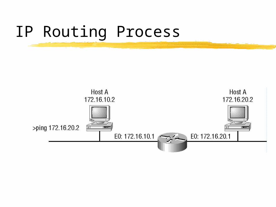
IP Routing Process
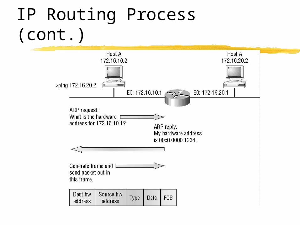
IP Routing Process (cont.)
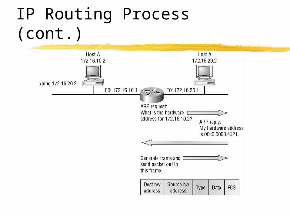
IP Routing Process (cont.)
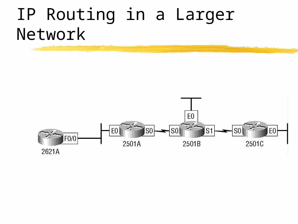
IP Routing in a Larger Network
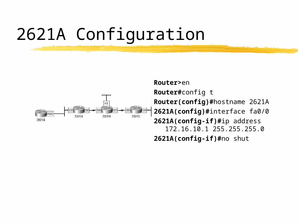
2621A Configuration
Router>enRouter#config tRouter(config)#hostname 2621A2621A(config)#interface fa0/02621A(config-if)#ip address
172.16.10.1 255.255.255.02621A(config-if)#no shut
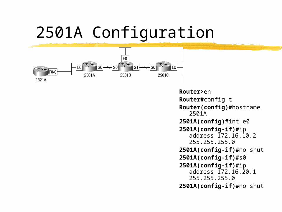
2501A Configuration
Router>enRouter#config tRouter(config)#hostname
2501A2501A(config)#int e02501A(config-if)#ip
address 172.16.10.2 255.255.255.0
2501A(config-if)#no shut2501A(config-if)#s02501A(config-if)#ip
address 172.16.20.1 255.255.255.0
2501A(config-if)#no shut
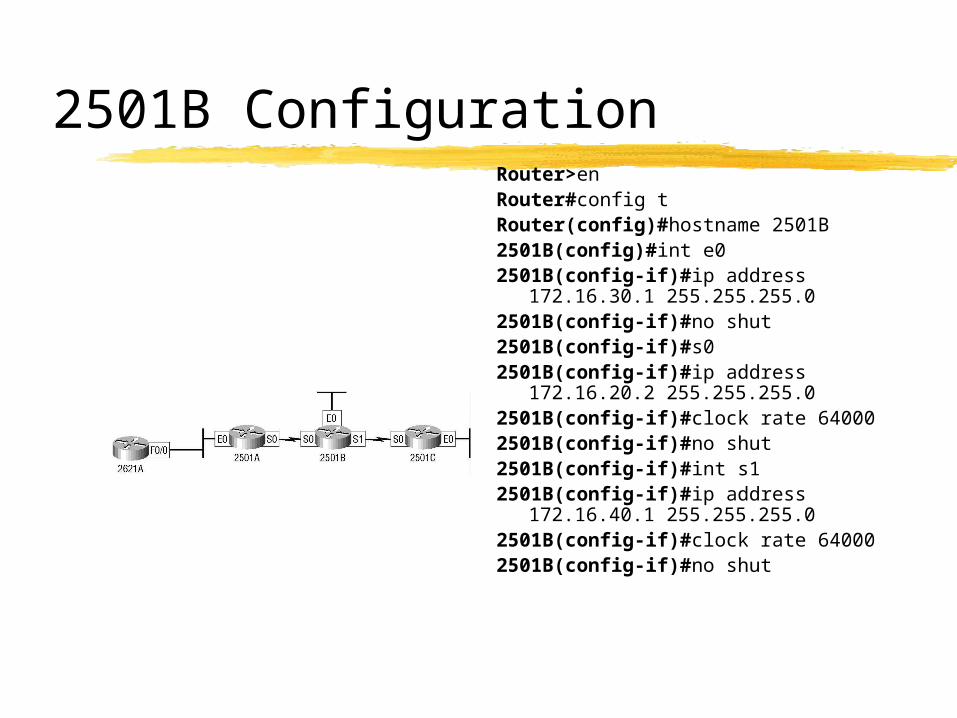
2501B ConfigurationRouter>enRouter#config tRouter(config)#hostname 2501B2501B(config)#int e02501B(config-if)#ip address
172.16.30.1 255.255.255.02501B(config-if)#no shut2501B(config-if)#s02501B(config-if)#ip address
172.16.20.2 255.255.255.02501B(config-if)#clock rate 640002501B(config-if)#no shut2501B(config-if)#int s12501B(config-if)#ip address
172.16.40.1 255.255.255.02501B(config-if)#clock rate 640002501B(config-if)#no shut
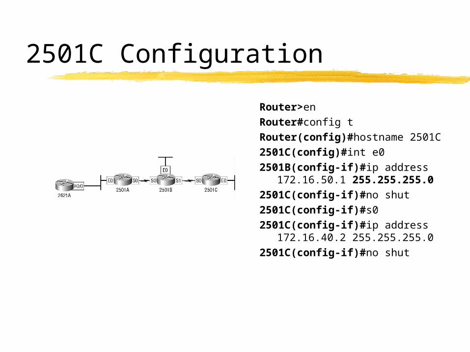
2501C Configuration
Router>enRouter#config tRouter(config)#hostname 2501C2501C(config)#int e02501B(config-if)#ip address
172.16.50.1 255.255.255.02501C(config-if)#no shut2501C(config-if)#s02501C(config-if)#ip address
172.16.40.2 255.255.255.02501C(config-if)#no shut
IP Routing in Our Network
Routing tables Configuration Types of routing
StaticDefaultDynamic
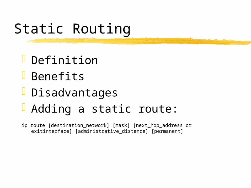
Static Routing
DefinitionBenefitsDisadvantagesAdding a static route:ip route [destination_network] [mask] [next_hop_address or exitinterface]
[administrative_distance] [permanent]
2621A & 2501A
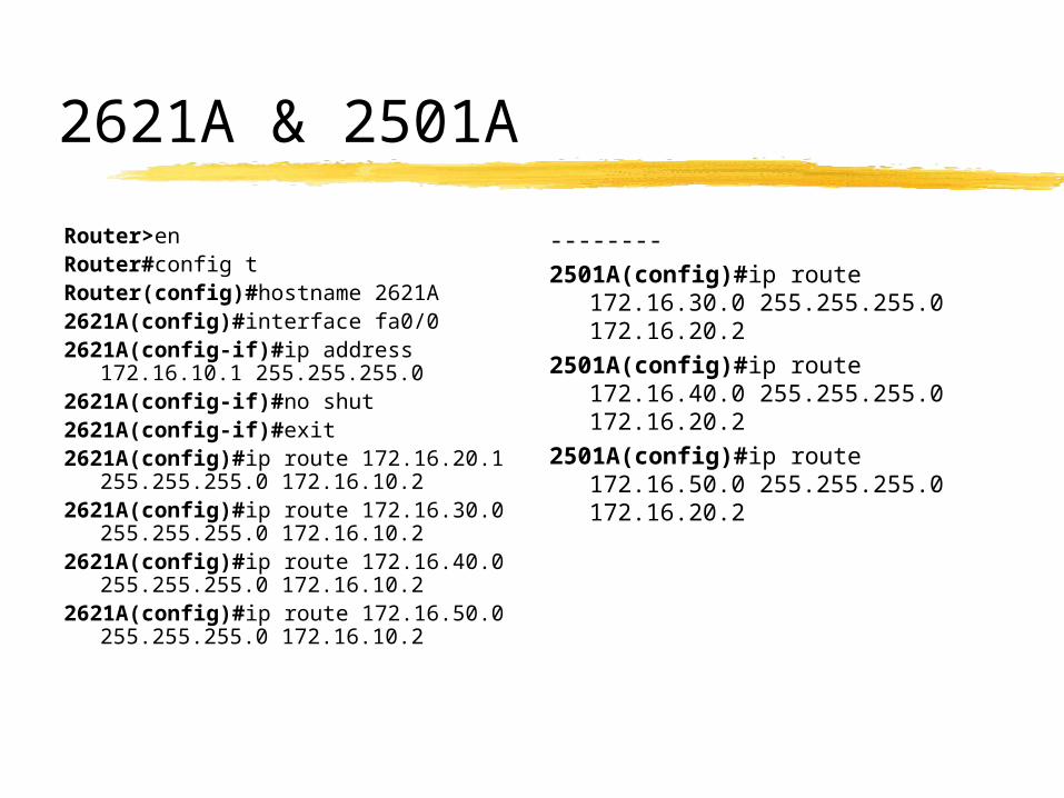
Router>enRouter#config tRouter(config)#hostname 2621A2621A(config)#interface fa0/02621A(config-if)#ip address
172.16.10.1 255.255.255.02621A(config-if)#no shut2621A(config-if)#exit2621A(config)#ip route 172.16.20.1
255.255.255.0 172.16.10.22621A(config)#ip route 172.16.30.0
255.255.255.0 172.16.10.22621A(config)#ip route 172.16.40.0
255.255.255.0 172.16.10.22621A(config)#ip route 172.16.50.0
255.255.255.0 172.16.10.2
--------2501A(config)#ip route
172.16.30.0 255.255.255.0 172.16.20.2
2501A(config)#ip route 172.16.40.0 255.255.255.0 172.16.20.2
2501A(config)#ip route 172.16.50.0 255.255.255.0 172.16.20.2
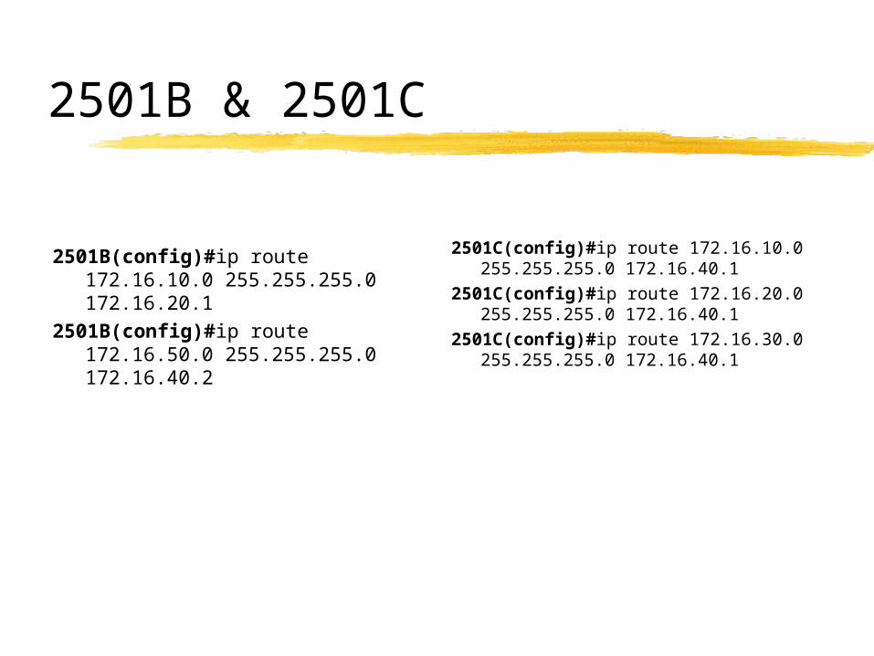
2501B & 2501C
2501B(config)#ip route 172.16.10.0 255.255.255.0 172.16.20.1
2501B(config)#ip route 172.16.50.0 255.255.255.0 172.16.40.2
2501C(config)#ip route 172.16.10.0 255.255.255.0 172.16.40.1
2501C(config)#ip route 172.16.20.0 255.255.255.0 172.16.40.1
2501C(config)#ip route 172.16.30.0 255.255.255.0 172.16.40.1
Default Routing
Definition
Configuration
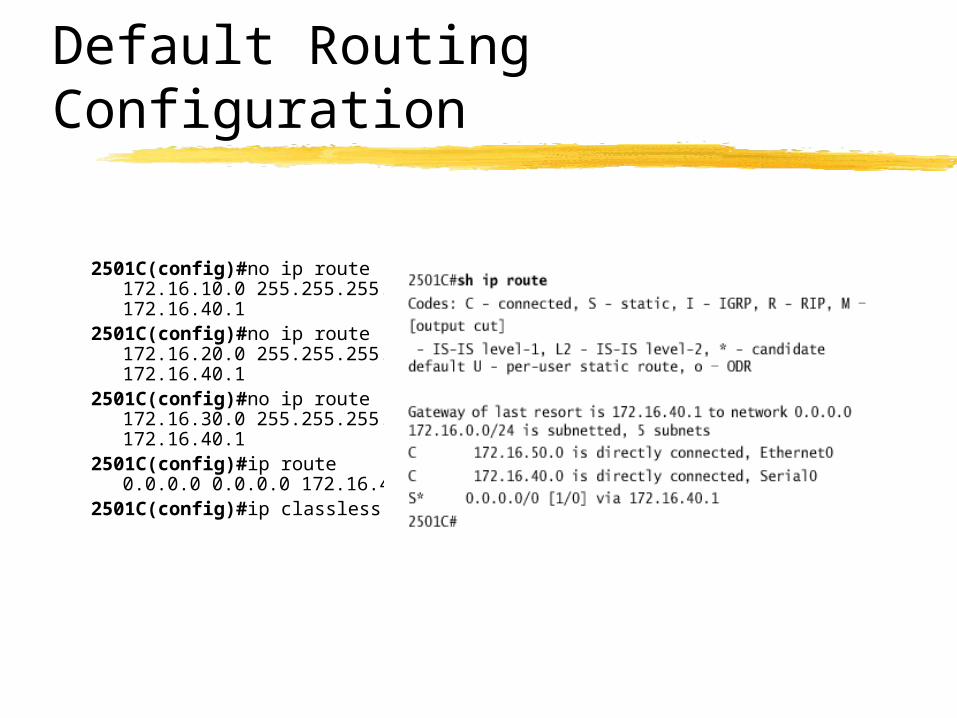
Default Routing Configuration
2501C(config)#no ip route 172.16.10.0 255.255.255.0 172.16.40.1
2501C(config)#no ip route 172.16.20.0 255.255.255.0 172.16.40.1
2501C(config)#no ip route 172.16.30.0 255.255.255.0 172.16.40.1
2501C(config)#ip route 0.0.0.0 0.0.0.0 172.16.40.1
2501C(config)#ip classless
Dynamic Routing
Definition
Types of Routing Protocols Interior Gateway Protocol (IGP) Exterior Gateway Protocol (EGP)
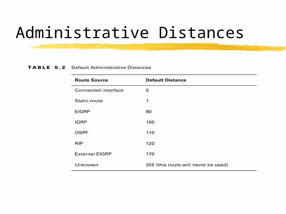
Administrative Distances
Classes of Routing Protocols
Classes
Distance Vector
Link State
Hybrid
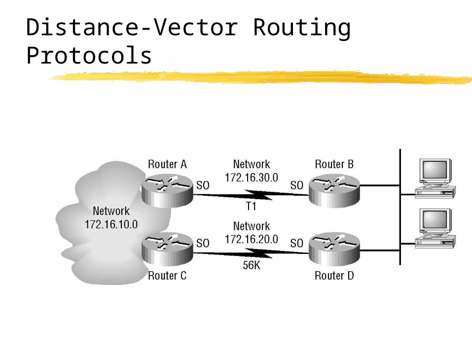
Distance-Vector Routing Protocols
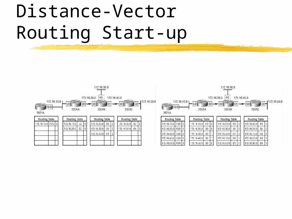
Distance-Vector Routing Start-up
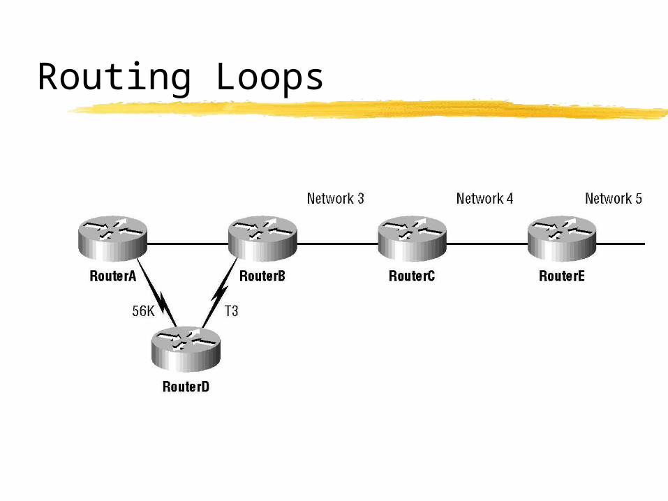
Routing Loops
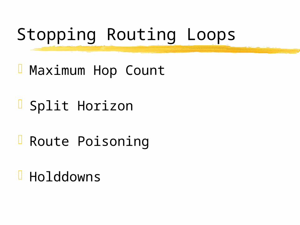
Stopping Routing Loops
Maximum Hop Count
Split Horizon
Route Poisoning
Holddowns
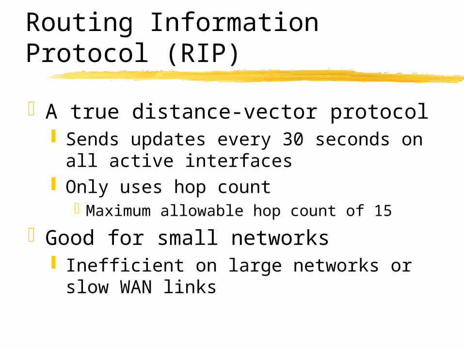
Routing Information Protocol (RIP)
A true distance-vector protocol Sends updates every 30 seconds on all
active interfaces Only uses hop count
Maximum allowable hop count of 15
Good for small networks Inefficient on large networks or slow
WAN links
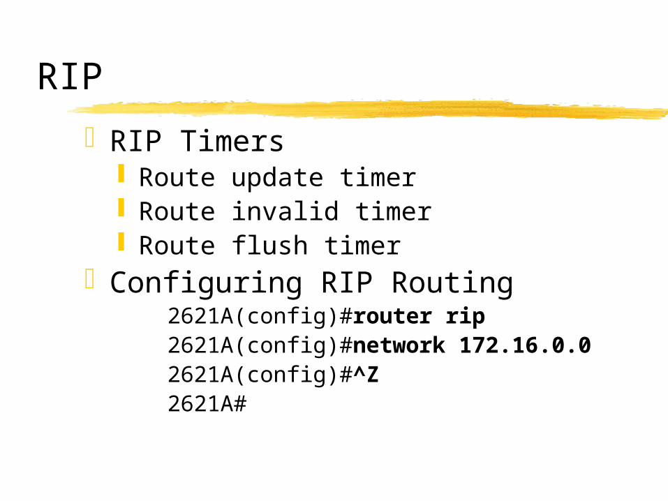
RIP
RIP Timers Route update timer Route invalid timer Route flush timer
Configuring RIP Routing2621A(config)#router rip2621A(config)#network
172.16.0.02621A(config)#^Z2621A#
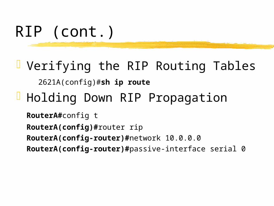
RIP (cont.)
Verifying the RIP Routing Tables2621A(config)#sh ip route
Holding Down RIP PropagationRouterA#config t
RouterA(config)#router ripRouterA(config-router)#network 10.0.0.0RouterA(config-router)#passive-interface
serial 0
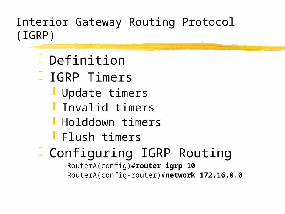
Interior Gateway Routing Protocol (IGRP)
DefinitionIGRP Timers
Update timers Invalid timers Holddown timers Flush timers
Configuring IGRP RoutingRouterA(config)#router igrp 10RouterA(config-router)#network 172.16.0.0
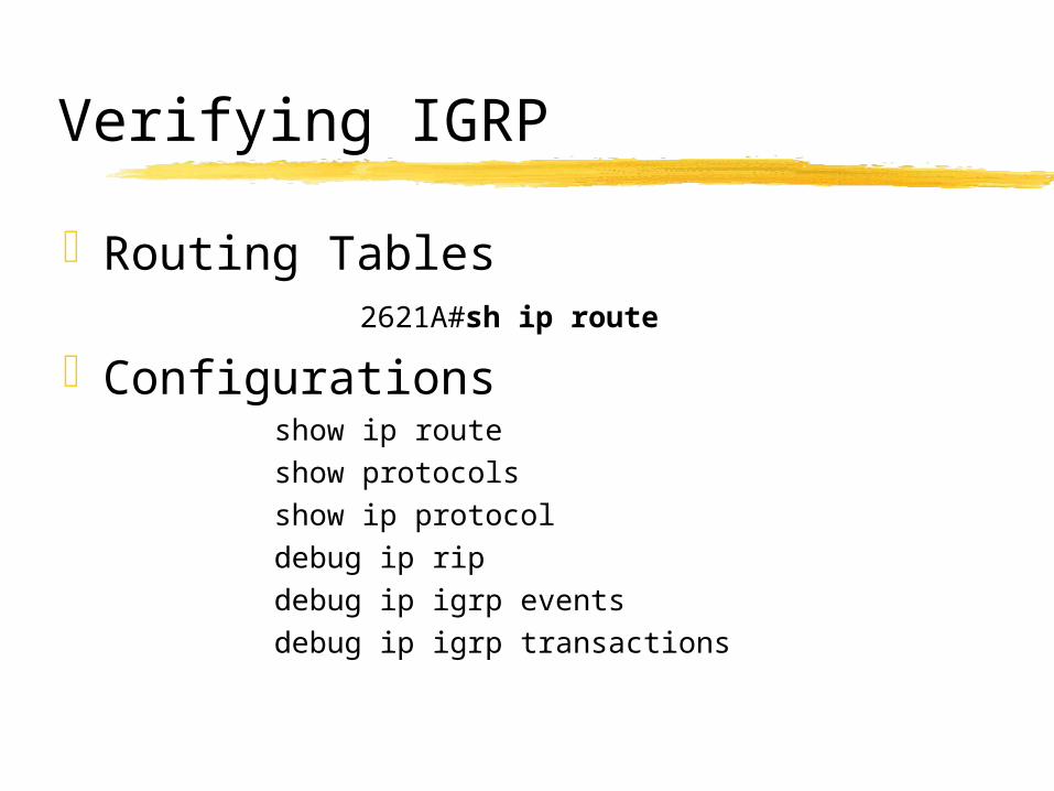
Verifying IGRP
Routing Tables2621A#sh ip route
Configurationsshow ip routeshow protocolsshow ip protocoldebug ip ripdebug ip igrp eventsdebug ip igrp transactions
Summary
Stated the IP routing processCreated and verified static routingCreated and verified default routingResolved network loops in distance-
vector routingConfigured and verified RIP routingConfigured and verified IGRP routing