bridge design manual m 23-50.06 july 2011 - washington state
TRANSCRIPT

WSDOT Bridge Design Manual M 23-50.18 Page 2-i June 2018
Chapter 2 Preliminary Design Contents
2.1 Preliminary Studies . . . . . . . . . . . . . . . . . . . . . . . . . . . . . . . . . . . . . . . . . . . . . . . . . . .2-1
2.2 Preliminary Plan . . . . . . . . . . . . . . . . . . . . . . . . . . . . . . . . . . . . . . . . . . . . . . . . . . . . . .2-72.2.1 Development of the Preliminary Plan . . . . . . . . . . . . . . . . . . . . . . . . . . . . . . . . . .2-72.2.2 Documentation . . . . . . . . . . . . . . . . . . . . . . . . . . . . . . . . . . . . . . . . . . . . . . . . . .2-92.2.3 General Factors for Consideration . . . . . . . . . . . . . . . . . . . . . . . . . . . . . . . . . . . 2-102.2.4 Permits . . . . . . . . . . . . . . . . . . . . . . . . . . . . . . . . . . . . . . . . . . . . . . . . . . . . . . 2-122.2.5 Preliminary Cost Estimate . . . . . . . . . . . . . . . . . . . . . . . . . . . . . . . . . . . . . . . . . 2-132.2.6 Approvals . . . . . . . . . . . . . . . . . . . . . . . . . . . . . . . . . . . . . . . . . . . . . . . . . . . . 2-13
2.3 Preliminary Plan Criteria . . . . . . . . . . . . . . . . . . . . . . . . . . . . . . . . . . . . . . . . . . . . . . 2-162.3.1 Highway Crossings . . . . . . . . . . . . . . . . . . . . . . . . . . . . . . . . . . . . . . . . . . . . . . 2-162.3.2 Railroad Crossings . . . . . . . . . . . . . . . . . . . . . . . . . . . . . . . . . . . . . . . . . . . . . . 2-202.3.3 Water Crossings . . . . . . . . . . . . . . . . . . . . . . . . . . . . . . . . . . . . . . . . . . . . . . . . 2-222.3.4 Bridge Widening . . . . . . . . . . . . . . . . . . . . . . . . . . . . . . . . . . . . . . . . . . . . . . . . 2-242.3.5 Temporary Bridges . . . . . . . . . . . . . . . . . . . . . . . . . . . . . . . . . . . . . . . . . . . . . . 2-242.3.6 Retaining Walls and Noise Walls . . . . . . . . . . . . . . . . . . . . . . . . . . . . . . . . . . . . 2-252.3.7 Bridge Deck Drainage . . . . . . . . . . . . . . . . . . . . . . . . . . . . . . . . . . . . . . . . . . . . 2-252.3.8 Bridge Deck Protection Systems . . . . . . . . . . . . . . . . . . . . . . . . . . . . . . . . . . . . 2-252.3.9 Construction Clearances . . . . . . . . . . . . . . . . . . . . . . . . . . . . . . . . . . . . . . . . . . 2-252.3.10 Design Guides for Falsework Depth Requirements . . . . . . . . . . . . . . . . . . . . . . . 2-262.3.11 Inspection and Maintenance Access . . . . . . . . . . . . . . . . . . . . . . . . . . . . . . . . . . 2-27
2.4 Selection of Structure Type . . . . . . . . . . . . . . . . . . . . . . . . . . . . . . . . . . . . . . . . . . . 2-30
2.5 Aesthetic Considerations . . . . . . . . . . . . . . . . . . . . . . . . . . . . . . . . . . . . . . . . . . . . . 2-37
2.6 Miscellaneous . . . . . . . . . . . . . . . . . . . . . . . . . . . . . . . . . . . . . . . . . . . . . . . . . . . . . . 2-40
2.7 WSDOT Standards for Highway Bridges . . . . . . . . . . . . . . . . . . . . . . . . . . . . . . . . . 2-412.7.1 Design Elements . . . . . . . . . . . . . . . . . . . . . . . . . . . . . . . . . . . . . . . . . . . . . . . . 2-412.7.2 Detailing the Preliminary Plan . . . . . . . . . . . . . . . . . . . . . . . . . . . . . . . . . . . . . . 2-422.7.3 Bridge Design Minimum Requirements . . . . . . . . . . . . . . . . . . . . . . . . . . . . . . . 2-43
2.8 Bridge Security . . . . . . . . . . . . . . . . . . . . . . . . . . . . . . . . . . . . . . . . . . . . . . . . . . . . . 2-442.8.1 General . . . . . . . . . . . . . . . . . . . . . . . . . . . . . . . . . . . . . . . . . . . . . . . . . . . . . . 2-442.8.2 Design . . . . . . . . . . . . . . . . . . . . . . . . . . . . . . . . . . . . . . . . . . . . . . . . . . . . . . . 2-442.8.3 Design Criteria . . . . . . . . . . . . . . . . . . . . . . . . . . . . . . . . . . . . . . . . . . . . . . . . . 2-45
2.9 Bridge Standard Drawings . . . . . . . . . . . . . . . . . . . . . . . . . . . . . . . . . . . . . . . . . . . . 2-47

Chapter 2 Preliminary Design
Page 2-ii WSDOT Bridge Design Manual M 23-50.18 June 2018
2.10 Appendices . . . . . . . . . . . . . . . . . . . . . . . . . . . . . . . . . . . . . . . . . . . . . . . . . . . . . . . . 2-48Appendix 2.2-A1 Bridge Site Data General . . . . . . . . . . . . . . . . . . . . . . . . . . . . . . . . . . . 2-49Appendix 2.2-A2 Bridge Site Data Rehabilitation . . . . . . . . . . . . . . . . . . . . . . . . . . . . . . 2-50Appendix 2.2-A3 Bridge Site Data Stream Crossing . . . . . . . . . . . . . . . . . . . . . . . . . . . . . 2-51Appendix 2.2-A4 Preliminary Plan Checklist . . . . . . . . . . . . . . . . . . . . . . . . . . . . . . . . . . 2-52Appendix 2.2-A5 Request For Preliminary Geotechnical Information . . . . . . . . . . . . . . . 2-54
2.99 References . . . . . . . . . . . . . . . . . . . . . . . . . . . . . . . . . . . . . . . . . . . . . . . . . . . . . . . . . 2-56

WSDOT Bridge Design Manual M 23-50.18 Page 2-1 June 2018
Chapter 2 Preliminary Design
2.1 Preliminary StudiesDifferent levels of preliminary studies are discussed below. Not all are applicable to a specific project. Bridge and Structures Office should participate in all applicable studies. Reports from the studies should be filed for future reference.
2.1.1 Interdisciplinary Design StudiesRegion may set up an Interdisciplinary Design Team (IDT) to review the various design alternatives for major projects. The IDT is composed of members from Regions, HQ, outside agencies, and consulting firms. The members have different areas of expertise, contribute ideas, and participate in the selection of design alternatives. This work will often culminate in the publication of an Environmental Impact Statement (EIS).
Bridge designers may be asked to participate either as a support resource or as a member of the IDT.
2.1.2 Value Engineering StudiesValue Engineering (VE) is a review process and analysis of a design project. The VE team seeks to define the most cost-effective means of satisfying the basic function(s) of the project. Usually a VE study takes place before or during the time that the region is working on the design. Occasionally, a VE study examines a project with a completed PS&E. VE studies are normally required for projects with cost overruns.
The VE team is headed by a facilitator and is composed of members with different areas of expertise from Regions, HQ, outside agencies, and consulting firms. The Team Facilitator will lead the team through the VE process. The team will review Region’s project as defined by the project’s design personnel. The VE team will determine the basic function(s) that are served by the project, brainstorm all possible alternatives to serve the same function(s), evaluate the alternatives for their effectiveness to meet the project’s basic functions, determine costs, and prioritize and recommend alternatives. The VE team will prepare a report and present their findings to the region. The Region is then required to investigate and address the VE team’s findings in the final design.
Bridge designers may be asked to participate either as a support resource or as a member of the VE team. VE studies usually take place over a three to five day period.
Engineers participating in VE studies, Cost-Risk Assessment (CRA) or Cost Estimate and Validation Process (CEVP) meetings shall call the S&E Engineers and double check all costs when providing cost estimates at VE studies and CRA meetings.
2.1.3 Preliminary Recommendations for Bridge Rehabilitation ProjectsWhen the Region starts a bridge rehabilitation project, they will submit a written memo requesting that the Bridge and Structures Office make preliminary project recommendations.
The Bridge and Structures Office will review the as-built plans, load ratings, existing inspection and condition reports prepared by the Bridge Preservation Office (BPO), and schedule a site visit with Region and other stakeholders. Special inspection of certain portions of the structure may be included in the site visit or scheduled later with Region

Chapter 2 Preliminary Design
Page 2-2 WSDOT Bridge Design Manual M 23-50.18 June 2018
and BPO. The purpose of the inspections is to obtain more detailed information as to the bridge’s condition, to obtain dimensions and take photographs of details needed for the project recommendations.
Following the site visit, the next steps are:• Determine the load capacity of the existing bridge.• Determine what type of rehabilitation work is needed and time frame required
to accomplish the work.• Determine any special construction staging requirements. Can the bridge be totally
shut down for the rehabilitation period? How many lanes will need to be open? Can the work be accomplished during night closures or weekend closures?
• Develop various alternatives and cost estimates for comparison, ranging from “do nothing” to “new replacement”.
• Determine what the remaining life expectancies are for the various rehabilitation alternatives.
• Determine the cost of a new replacement bridge. If the cost for the rehabilitation is equal or greater than 60 percent of a new replacement bridge, a new replacement bridge is recommended.
The Bridge and Structures Office will provide Region with a written report with background information. The Region will be given an opportunity to review the draft report and to provide input prior to finalization.
The Bridge Project Support Engineer and Specifications & Estimates Engineers (S&E) provide bridge scoping cost estimates to Regions for their use in determining budgets during Region's project definition phase. The S&E Engineers will check the Bridge Project Support Engineer's estimate as well as check each other.
2.1.4 Preliminary Recommendations for New Bridge ProjectsThe Region will seek assistance from the Bridge and Structures Office when they are preparing a design project requiring new bridges. Similar to the procedures outlined above for rehabilitation projects. The Region will submit a written memo requesting that the bridge office make preliminary project recommendations. The Bridge and Structures Office will provide scope of work, cost estimate(s), and a summary of the preferred alternatives with recommendations. Face to face meetings with the Region project staff are recommended prior to sending a written memo.
The Bridge Project Support Engineer and Specifications & Estimates Engineers provide bridge scoping cost estimates to Regions for their use in determining budgets during Region's project definition phase. The S&E Engineers will check the Bridge Project Support Engineer's estimate as well as check each other.
2.1.5 Type, Size, and Location (TS&L) ReportsThe Federal Highway Administration (FHWA) requires that major or unusual bridges must have a Type, Size, and Location (TS&L) report prepared. The report will describe the project, proposed structure(s), cost estimates, other design alternatives considered, and recommendations. The report provides justification for the selection of the preferred alternative. A letter of approval by FHWA of the TS&L study is the basis for advancing the project to the design stage.
Preliminary Design Chapter 2
WSDOT Bridge Design Manual M 23-50.18 Page 2-3 June 2018
The FHWA should be contacted as early as possible in the Project Development stage because the FHWA requires a TS&L study for tunnels, movable bridges, unusual structures, and major structures. Smaller bridges that are unusual or bridge projects for Local Agencies may also require a TS&L study. Other projects, such as long viaducts, may not. Check with the Bridge Project Support Engineer to see if a TS&L report is necessary.
The preparation of the TS&L report is the responsibility of the Bridge and Structures Office. The TS&L cannot be submitted to FHWA until after the environmental documents have been submitted. However, TS&L preparation need not wait for environmental document approval, but may begin as soon as the bridge site data is available. See the Design Manual M 22-01 for the type of information required for a bridge site data submittal.
A. TS&L General
The designer should first review the project history in order to become familiar with the project. The environmental and design reports should be reviewed. The bridge site data should be checked so that additional data, maps, or drawings can be requested. A meeting with Region and a site visit should be arranged after reviewing the history of the project.
The Materials Laboratory Geotechnical Services Branch must be contacted early in the TS&L process in order to have foundation information. Specific recommendations on the foundation type must be included in the TS&L report. The Materials Laboratory Geotechnical Services Branch will submit a detailed foundation report for inclusion as an appendix to the TS&L report.
To determine the preferred structural alternative, the designer should:
l. Develop a list of all feasible alternatives. At this stage, the range of alternatives should be kept wide open. Brainstorming with the Design Unit Managers and other engineers can provide new and innovative solutions.
2 Eliminate the least desirable alternatives by applying the constraints of the project. Question and document the assumptions of any restrictions and constraints. There should be no more than four alternatives at the end of this step.
3. Perform preliminary design calculations for unusual or unique structural problems to verify that the remaining alternatives are feasible.
4. Compare the advantages, disadvantages, and costs of the remaining alternatives to determine the preferred alternative(s).
5. Visit the project site with the Region, Materials Laboratory Geotechnical Services Branch, and HQ Hydraulics staff.
FHWA expects specific information on scour and backwater elevations for the permanent bridge piers, as well as, for any temporary falsework bents placed in the waterway opening.
After the piers have been located, a memo requesting a Hydraulics Report should be sent to the HQ Hydraulics Unit. The HQ Hydraulics Unit will submit a report for inclusion as an appendix to the TS&L report.

Chapter 2 Preliminary Design
Page 2-4 WSDOT Bridge Design Manual M 23-50.18 June 2018
The State Bridge and Structures Architect should be consulted early in the TS&L study period. “Notes to the File” should be made documenting the aesthetic requirements and recommendations of the State Bridge and Structures Architect.
Cost backup data is needed for any costs used in the TS&L study. FHWA expects TS&L costs to be based on estimated quantities. This cost data is to be included in an appendix to the TS&L report. The quantities should be compatible with the S&E Engineer’s cost breakdown method. The Specifications & Estimates Engineers will check the designer's estimated costs included in TS&L reports. In the case of consultant prepared TS&L reports, the designer shall have the S&E Engineers check the construction costs.
B. TS&L Outline
The TS&L report should describe the project, the proposed structure, and give reasons why the bridge type, size, and location were selected.
1. Cover, Title Sheet, and Index
These should identify the project, owner, location and the contents of the TS&L.
2. Photographs
There should be enough color photographs to provide the look and feel of the bridge site. The prints should be numbered and labeled and the location indicated on a diagram.
3. Introduction
The introduction describes the report, references, and other reports used to prepare the TS&L study. The following reports should be listed, if used.• Design Reports and Supplements• Environmental Reports• Architectural Visual Assessment or Corridor Theme Reports• Hydraulic Report• Geotechnical Reports
4. Project Description
The TS&L report clearly defines the project. A vicinity map should be shown. Care should be taken to describe the project adequately but briefly. The project description summarizes the preferred alternative for the project design.
5. Design Criteria
The design criteria identify the AASHTO LRFD and AASHTO Guide Specifications that will be used in the bridge design. Sometimes other design criteria or special loadings are used. These criteria should be listed in the TS&L. Some examples in this category might be the temperature loading used for segmental bridges or areas defined as wetlands.
Preliminary Design Chapter 2
WSDOT Bridge Design Manual M 23-50.18 Page 2-5 June 2018
6. Structural Studies
The structural studies section documents how the proposed structure Type, Size, and Location were determined. The following considerations should be addressed.• Aesthetics• Cost estimates• Geometric constraints• Project staging and
stage construction requirements
• Foundations• Hydraulics• Feasibility of
construction• Structural constraints• Maintenance
This section should describe how each of these factors leads to the preferred alternative. Show how each constraint eliminated or supported the preferred alternatives. Here are some examples. “Prestressed concrete girders could not be used because environmental restrictions required that no permanent piers could be placed in the river. This requires a 230-foot clear span.” “Restrictions on falsework placement forced the use of self supporting precast concrete or steel girders.”
7. Executive Summary
The executive summary should be able to “stand alone” as a separate document. The project and structure descriptions should be given. Show the recommended alternative(s) with costs and include a summary of considerations used to select preferred alternatives or to eliminate other alternatives.
8. Drawings
Preliminary plan drawings of the recommended alternative are included in an appendix. The drawings show the plan, elevation, and typical section. For projects where alternative designs are specified as recommended alternatives, preliminary plan drawings for each of the different structure types shall be included. Supplemental drawings showing special features, such as complex piers, are often included to clearly define the project.
C. Reviews and Submittals
While writing the TS&L report, all major decisions should be discussed with the Design Unit Manager, who can decide if the Bridge Design Engineer needs to be consulted. A peer review meeting with the Bridge Design Engineer should be scheduled at the 50 percent completion stage. If applicable, the FHWA Bridge Engineer should be invited to provide input.
The final report must be reviewed, approved, and the Preliminary Plan drawings signed by the State Bridge and Structures Architect, the Bridge Project Support Engineer, the Bridge Design Engineer, and the Bridge and Structures Engineer. The TS&L report is submitted with a cover letter to FHWA signed by the Bridge and Structures Engineer.

Chapter 2 Preliminary Design
Page 2-6 WSDOT Bridge Design Manual M 23-50.18 June 2018
2.1.6 Alternate Bridge DesignsBridge site conditions or current market conditions may justify the creation of alternate bridge designs. WSDOT has successfully used alternate bridge designs in the past to obtain best-value bridge design and construction solutions for specific locations. Alternate bridge designs may be considered when the following conditions can be satisfied:• Construction cost estimates for the alternate designs should be comparable (within
10 percent). Cost estimates should include anticipated life-cycle costs (painting, maintenance, inspection). Periods of market uncertainty, with associated structure cost fluctuations, can provide further justification for alternate bridge designs.
• Region staff must approve the design expenditures for the preparation of alternate bridge designs, including preliminary plans, final bridge plans, specifications and construction cost estimates.
• WSDOT Bridge Office staffing levels and design schedules should allow for the preparation of alternate bridge designs.
• Variations in pier location may be required in order to optimize superstructure design for different alternates. Environmental constraints, geotechnical, hydraulic and scour conditions all need to allow for variations in pier location.
• Construction staging and traffic control must be determined for the alternates.• Alternate bridge design concepts must be reviewed and approved by the Bridge and
Structures Architect.

Preliminary Design Chapter 2
WSDOT Bridge Design Manual M 23-50.18 Page 2-7 June 2018
2.2 Preliminary PlanThe Preliminary Plan preparation stage is the most important phase of bridge and buried structure design because it is the basis for the final design. The Preliminary Plan should completely define the bridge and buried structure geometry so the final roadway design by the Regions and the structural design by the Bridge and Structures Office can take place with minimal revisions.
During the Region’s preparation of the highway design, they also begin work on the structure site data. Region submits the structure site data to the Bridge and Structures Office, which initiates the start of the Preliminary Plan stage. Information that must be included as part of the structure site data submittal is described in Design Manual M 22-01 and Appendices 2.2-A1, 2.2-A2, and 2.2-A3.
2.2.1 Development of the Preliminary PlanA. Responsibilities
In general, the responsibilities of the designer, checker, detailer, and Design Unit Manager are described in Section 1.2.2. The Preliminary Plan Engineer is responsible for developing a preliminary plan for the bridge or buried structure. The preliminary plan must be compatible with the geometric, aesthetic, staging, geotechnical, hydraulic, financial, structural requirements and conditions at the bridge site.
Upon receipt of the structure site data from the Region, the Preliminary Plan Engineer shall review it for completeness and verify that what the project calls for is realistic and structurally feasible. Any omissions or corrections are to be immediately brought to the Region’s attention so that revised site data, if required, can be resubmitted to avoid jeopardizing the bridge design schedule.
The Design Unit Manager shall be kept informed of progress on the preliminary plan so that the schedule can be monitored. If problems develop, the Design Unit Manager can request adjustments to the schedule or allocate additional manpower to meet the schedule. The Preliminary Plan Engineer must keep the job file up-to-date by documenting all conversations, meetings, requests, questions, and approvals concerning the project. Notes-to-the-designer, and details not shown in the preliminary plan shall be documented in the job file.
The checker shall provide an independent review of the plan, verifying that it is in compliance with the site data as provided by the Region and as corrected in the job file. The plan shall be compared against the Preliminary Plan checklist (see Appendix 2.2-A4) to ensure that all necessary information is shown. The checker is to review the plan for consistency with office design practice, detailing practice, and for constructability.
The preliminary plan shall be drawn using current office CAD equipment and software by the designer or detailer.

Chapter 2 Preliminary Design
Page 2-8 WSDOT Bridge Design Manual M 23-50.18 June 2018
B. Site Reconnaissance
The structure site data submitted by the Region will include photographs and/or a video of the site. Even for minor projects, this may not be enough information for the designer to work from to develop a preliminary plan. For most bridge projects, site visits are necessary.
Site visits with Region project staff and other project stakeholders, such as, Materials Laboratory Geotechnical Services Branch, HQ Hydraulics, and Region Design should be arranged with the knowledge and approval of the Bridge Project Support Engineer.
C. Coordination
The designer is responsible for coordinating the design and review process throughout the project. This includes seeking input from various WSDOT units and outside agencies. The designer should consult with Materials Laboratory Geotechnical Services Branch, HQ Hydraulics, Bridge Preservation Office, and Region design and maintenance, and other resources for their input.
D. Consideration of Alternatives
In the process of developing the Preliminary Plan, the designer should brainstorm, develop, and evaluate various design alternatives. See Section 2.2.3 General Factors for Consideration and how they apply to a particular site. See also Section 2.1.5A. Preliminary design calculations shall be done to verify feasibility of girder span and spacing, falsework span capacity, geometry issues, and construction clearances. Generally, the number of alternatives will usually be limited to only a few for most projects. For some smaller projects and most major projects, design alternatives merit development and close evaluation. The job file should contain reasons for considering and rejecting design alternatives. This provides documentation for the preferred alternative.
E. Designer Recommendation
The designer should be able to make a recommendation for the preferred alternative after a thorough analysis of the needs and limitations of the site, studying all information, and developing and evaluating the design alternatives for the project. At this stage, the designer should discuss the recommendation with the Bridge Project Support Engineer.
F. Concept Approval
For some projects, the presentation, in “E” above, to the Bridge Project Support Engineer will satisfy the need for concept approval. Large complex projects, projects of unique design, or projects where two or more alternatives appear viable, should be presented to the Bridge Project Unit Manager and Bridge Design Engineer for his/her concurrence before plan development is completed. For unique or complex projects a presentation to the Region Project Engineer, and Bridge and Structures Office Peer Review Committee may be appropriate.

Preliminary Design Chapter 2
WSDOT Bridge Design Manual M 23-50.18 Page 2-9 June 2018
2.2.2 DocumentationA. Job File
An official job file is created by the Bridge Preliminary Plan Detailer when a memo transmitting site data from the Region is received by the Bridge and Structures Office. This job file serves as a depository for all communications and resource information for the job. Scheduling and time estimates are kept in this file, as well as cost estimates, preliminary quantities, and documentation of all approvals. Records of important telephone conversations and copies of e-mails approving decisions are also kept in the job file.
After completing the Preliminary Plan, the job file continues to serve as a depository for useful communications and documentation for all pertinent project related information and decisions during the design process through and including preparation of the Final Bridge PS&E.
B. Structure Site Data
All Preliminary Plans are developed from structure site data submitted by the Region. This submittal will consist of a memorandum intra-departmental communication, and appropriate attachments as specified by the Design Manual M 22-01. When this information is received, it should be reviewed for completeness so that missing or incomplete information can be noted and requested.
C. Request for Preliminary Foundation Data
A request for preliminary foundation data is sent to the Geotechnical Services Branch to solicit any foundation data that is available at the preliminary bridge design stage. See Appendix 2.2-A5. The Materials Laboratory Geotechnical Services Branch is provided with approximate dimensions for the overall structure length and width, approximate number of intermediate piers (if applicable), and approximate stations for beginning and end of structure on the alignment.
Based on test holes from previous construction in the area, geological maps, and soil surveys. The Materials Laboratory Geotechnical Services Branch responds by memo and a report with an analysis of what foundation conditions are likely to be encountered and what foundation types are best suited for the bridge site.
D. Request for Preliminary Hydraulics Data
A Request for preliminary hydraulics data is sent to the Hydraulics Branch to document hydraulic requirements that must be considered in the structure design. The Hydraulics Branch is provided a contour plan and other bridge site data.
The Hydraulics Branch will send a memo providing the following minimum data: seal vent elevations, normal water, 100-year and 500-year flood elevations and flows (Q), pier configuration, scour depth and minimum footing cover required, ice pressure, minimum waterway channel width, riprap requirements, and minimum clearance required to the 100-year flood elevation.

Chapter 2 Preliminary Design
Page 2-10 WSDOT Bridge Design Manual M 23-50.18 June 2018
E. Design Report or Design Summary and Value Engineering Studies
Some bridge construction projects have a Design File Report or Design Summary prepared by the Region. This is a document, which includes design considerations and conclusions reached in the development of the project. It defines the scope of work for the project. It serves to document the design standards and applicable deviations for the roadway alignment and geometry. It is also an excellent reference for project history, safety and traffic data, environmental concerns, and other information. If a VE study was done on the bridge, the report will identify alternatives that have been studied and why the recommended alternative was chosen.
F. Other Resources
For some projects, preliminary studies or reports will have been prepared. These resources can provide additional background for the development of the Preliminary Plan.
G. Notes
Notes of meetings with Regions and other project stakeholders shall be included in the job file.
2.2.3 General Factors for ConsiderationMany factors must be considered in preliminary bridge design. Some of the more common of these are listed in general categories below. These factors will be discussed in appropriate detail in subsequent portions of this manual.
A. Site Requirements
Topography Alignment (tangent, curved, skewed) Vertical profile and superelevation Highway Class and design speed Proposed or existing utilities
B. Safety
Feasibility of falsework (impaired clearance and sight distance, depth requirements, see Section 2.3.10) Density and speed of traffic Detours or possible elimination of detours by construction staging Sight distance Horizontal clearance to piers Hazards to pedestrians, bicyclists
C. Economic
Funding classification (federal and state funds, state funds only, local developer funds) Funding level Bridge preliminary cost estimate

Preliminary Design Chapter 2
WSDOT Bridge Design Manual M 23-50.18 Page 2-11 June 2018
D. Structural
Limitation on structure depth Requirements for future widening Foundation and groundwater conditions Anticipated settlement Stage construction Falsework limitations
E. Environmental
Site conditions (wetlands, environmentally sensitive areas, and cultural resources) Environmental requirements Mitigating measures Construction access
F. Aesthetic
General appearance Compatibility with surroundings and adjacent structures Visual exposure and experience for public
G. Construction
Ease of construction Falsework clearances and requirements Erection problems Hauling difficulties and access to site Construction season Time limit for construction
H. Hydraulic
Bridge deck drainage Stream flow conditions and drift Passage of flood debris Scour, effect of pier as an obstruction (shape, width, skew, number of columns) Bank and pier protection Consideration of a culvert as an alternate solution Permit requirements for navigation and stream work limitations
I. Maintenance
Concrete vs. Steel Expansion joints Bearings Deck protective systems Inspection and Maintenance Access (UBIT clearances) (see Figure 2.3.11-1)
J. Other
Prior commitments made to other agency officials and individuals of the community Recommendations resulting from preliminary studies
K. Bridge Security
Mitigation measures for the inappropriate and illegal access to the bridge Employing the methods of Crime Prevention Through Environmental Design (CPTED)

Chapter 2 Preliminary Design
Page 2-12 WSDOT Bridge Design Manual M 23-50.18 June 2018
2.2.4 PermitsA. Coast Guard
As outlined in the Design Manual M 22-01, Additional Data for Waterway Crossings, the Bridge and Structures Office is responsible for coordinating and applying for Coast Guard permits for bridges over waterways. The Coast Guard Liaison Engineer in the Bridge Project Unit of the Bridge and Structures Office handles this.
A determination of whether a bridge project requires a Coast Guard permit is typically determined by Region Environmental during the early scoping phase. This scoping is done before the bridge site data is sent to the Bridge and Structures Design Office.
The Region Design Engineer should request that the Environmental Coordinator consult with the Coast Guard Liaison Engineer prior to sending the bridge site data if possible.
Generally, tidal-influenced waterways and waterways used for commercial navigation will require Coast Guard permits. See the Design Manual M 22-01, chapter covering Environmental Permits and Approvals, or the Environmental Manual Chapter 500 for general permitting information. Section 9 Permit – Bridge Work in Navigable Waters can be found on the WSDOT Federal Environmental Permits and Approval web page, www.wsdot.wa.gov/environment/permitting/permitfsl.htm. Permitting procedures are available on the WSDOT Environmental Permitting tools and help page, www.wsdot.wa.gov/environment/permitting/permittools.htm
For all waterway crossings, the Coast Guard Liaison Engineer is required to initial the Preliminary Plan as to whether a Coast Guard permit or exemption is required. This box regarding Coast Guard permit status is located in the center left margin of the plan. If a permit is required, the permit target date will also be noted. The reduced print, signed by the Coast Guard Liaison Engineer, shall be placed in the job file.
The work on developing the permit application should be started before the bridge site data is complete so that it is ready to be sent to the Coast Guard at least eight months prior to the project ad date. The Coast Guard Liaison Engineer should be given a copy of the preliminary plans from which to develop the Coast Guard Application plan sheets, which become part of the permit.
B. Other
All other permits will be the responsibility of the Region (see the Design Manual M 22-01). The Bridge and Structures Office may be asked to provide information to the Region to assist them in making applications for these permits.

Preliminary Design Chapter 2
WSDOT Bridge Design Manual M 23-50.18 Page 2-13 June 2018
2.2.5 Preliminary Cost EstimateA preliminary cost estimate should be developed when the bridge type, foundation type, deck area and adjacent retaining walls are determined. At the Preliminary Plan stage the cost estimate is based on square-foot costs taken from the Chapter 12 and adjusted for structure specifics. Consult with a Specifications and Estimates Engineer. The preliminary cost estimate is based on recent bidding history on similar structures, degree of difficulty of construction, inflation trends, and length of time until Ad Date, and time for completion of construction. It is considered accurate to within 15 percent, but should be accurate enough to preclude a surprise increase at the time of the Engineer’s estimate, which is based on completed design quantities. The preliminary cost estimate shall be updated frequently as changes are made to the Preliminary Plan or new data influences the costs.
After a Preliminary Plan has been developed, but before sending to the Bridge Design Engineer for signature, the Preliminary Plan and Preliminary Bridge Geotechnical Information shall be submitted to one of the Bridge Specifications and Estimates Engineers. The information presented to the S&E Engineer shall include the complete Preliminary Plan and all backup data previously prepared on costs for the structures (such as preliminary quantity calculations, preliminary foundation type selection, etc,). The S&E Engineer will review the Preliminary Plan, prepare, sign, and date a cost estimate summary sheet, and return the package to the designer. When the Preliminary Plan is presented to the Bridge Design Engineer, the submittal shall include the summary sheet prepared by the S&E Engineer. The summary sheet and backup data will then be placed in the job file. Do not send the summary sheet to the Region.
After submittal of the Preliminary Plan to the Region, the Region shall be notified immediately of any increases in the preliminary cost estimate during the structural design.
2.2.6 ApprovalsA. State Bridge and Structures Architect/Specialists
For all preliminary plans, the State Bridge and Structures Architect and appropriate specialists should be aware and involved when the designer is first developing the plan. The State Bridge and Structures Architect and specialists should be given a print of the plan by the Preliminary Plan Engineer. This is done prior to checking the preliminary plan. The State Bridge and Structures Architect and specialist will review, approve, sign and date the print. This signed print is placed in the job file. If there are any revisions, which affect the aesthetics of the approved preliminary plan, the State Bridge and Structures Architect should be asked to review and approve, by signature, a print showing the revisions, which change elements of aesthetic significance.
For large, multiple bridge projects, the State Bridge and Structures Architect should be contacted for development of a coordinated architectural concept for the project corridor.
The architectural concept for a project corridor is generally developed in draft form and reviewed with the project stakeholders prior to finalizing. When finalized, it should be signed by the Region Administrator or his/her designee.
Approval from the State Bridge and Structures Architect is required on all retaining walls and noise wall aesthetics including finishes and materials, and configuration.

Chapter 2 Preliminary Design
Page 2-14 WSDOT Bridge Design Manual M 23-50.18 June 2018
In order to achieve superstructure type optimization and detailing consistency, the following guidelines shall be used for the preparation of all future Preliminary Plans:• Preliminary Plans for all steel bridges and structures shall be reviewed by the
Steel Specialist.• Preliminary Plans for all concrete bridges and structures shall be reviewed by the
Concrete Specialist.• Detailing of all Preliminary Plans shall be reviewed by the Preliminary Plans
Detailing Specialist.
These individuals shall signify their approval by signing the Preliminary Plan in the Architect/Specialist block on the first plan sheet, together with the State Bridge and Structures Architect.
B. Bridge Design
The Bridge Project Unit Manager signs the Preliminary Plan after it has been checked and approved by the Architect/Specialists. At this point, it is ready for review, approval, and signing by the Bridge Design Engineer.
After the Bridge Design Engineer has signed the Preliminary Plan, it is returned to the designer. The designer places the original signed Preliminary Plan in the job file and enters the names of the signers in the signature block. This Preliminary Plan will be sent to Region for their review and approval by email.
The email includes the preliminary plan and the WSDOT Form 230-038 Not Included in Bridge Quantities List and a brief explanation of the preliminary cost estimate. This is a list of non-bridge items that appear on the bridge Preliminary Plan and eventually will be covered in the Region’s design plans.
The following should be included in the email distribution list with attachments:
1. FHWA Washington Division Bridge Engineer (when project has Federal Funding)
2. Region Project Engineer, Design Team Leader and Designer, and the Region Project Development Engineer or equivalent.
3. Bridge Projects Unit Manager
4. Bridge Design Unit Manager, State Geotechnical Engineer,
5. HQ Hydraulics Engineer (when it is a water crossing),
6. Bridge Management Engineer (when it is a replacement),
7. Bridge Preservation Engineer,
8. HQ RR Liaison Engineer (when a railroad is involved), and Region Traffic Engineer (when ITS is required).
9. The Bridge Scheduling Engineer
10. Region and HQ Program Management Engineers.

Preliminary Design Chapter 2
WSDOT Bridge Design Manual M 23-50.18 Page 2-15 June 2018
C. Region
Prior to the completion of the preliminary plan, the designer should meet with the Region to discuss the concept, review the list of items to be included in the “Not Included in Bridge Quantities List” and get their input.
The Region will review the preliminary plan for compliance and agreement with the original site data. They will work to answer any “Notes to the Region” that have been listed on the plan. When this review is complete, the Regional Administrator, or his/her designee, will sign the plan. The Region will send back a print of the signed plan with any comments noted in red (additions) and green (deletions) along with responses to the questions raised in the “Notes to the Region.”
D. Railroad
When a railroad is involved with a structure on a Preliminary Plan, the HQ RR Liaison Engineer of the Design Office must be involved during the plan preparation process. A copy of the Preliminary Plan is sent to the HQ RR Liaison Engineer, who then sends a copy to the railroad involved for their comments and approval.
The railroad will respond with approval by letter to the HQ RR Liaison Engineer. A copy of this letter is then routed to the Bridge and Structures Office and then placed in the job file.
For design plans prepared within the Bridge and Structures Office, the Design Unit Manager or lead designer will be responsible for coordinating and providing shoring plans for structures adjacent to railroads. It is recommended that the Construction Support Unit design, prepare, stamp, and sign shoring plans. However, the design unit may elect to design, prepare, stamp, and sign shoring plans.
For consultant prepared design plans, the Design Unit Manager or lead reviewer will be responsible for coordinating and having the consultant design shoring plans for structures adjacent to railroads. The Construction Support Unit has design criteria and sample plan details which can be used by the design units and consultants.
A Construction Support engineer is available to attend design project kick-off meetings if there is a need for railroad shoring plans or other constructability issues associated with the project. Regardless of who prepares the bridge plans, all shoring plans should be reviewed by the Construction Support Unit before they are submitted for railroad review and approval at the 50 percent Final PS&E stage.
For completed shelf projects, the S&E Engineer will contact the Region Project Engineer and inform the Design Unit Manager or lead reviewer on the need for shoring plans for structures adjacent to railroads. If shoring plans are required, the Design Unit Manager or lead designer may ask the Construction Support Unit to prepare shoring plans.
At the 50 percent PS&E plan completion stage or sooner if possible, especially for seismic retrofit project, the S&E Engineer will send four (4) copies of the layout, foundation plan, temporary shoring plans, and appropriate special provision section for structures adjacent to railroads to the HQ RR Liaison Engineer, who will submit this package to the appropriate railroad for review and approval. The shoring plans shall show the pressure loading diagram and calculations to expedite the railroad’s review and approval.

Chapter 2 Preliminary Design
Page 2-16 WSDOT Bridge Design Manual M 23-50.18 June 2018
2.3 Preliminary Plan Criteria2.3.1 Highway Crossings
A. General
A highway crossing is defined as a grade separation between two intersecting roadways. Naming convention varies slightly between mainline highway crossings and ramp highway crossings, but essentially, all bridges carry one highway, road, or street over the intersecting highway, road, or street.
1. Mainline Highway Crossings
Names for mainline highway crossings are defined by the route designation or name of state highway, county road, or city street being carried over another highway, road, or street.
For example, a bridge included as part of an interchange involving I-205 and SR 14 and providing for passage of traffic on I-205 under SR 14 would be named SR 14 Over I-205 (followed by the bridge number).
2. Ramp Highway Crossings
Names for ramp highway crossings are defined by the state highway route numbers being connected, the directions of travel being connected, and the designation or name of the highway, road, or street being bridged.
For example, a bridge in the Hewitt Avenue Interchange connecting traffic from westbound US 2 to northbound I-5 and passing over Everett Street would be named 2W-5N Ramp Over Everett Street (followed by the bridge number). A bridge connecting traffic from northbound I-5 to westbound SR 518 and passing over northbound I-405 and a ramp connecting southbound I-405 to northbound I-5 would be named 5N-518W Over 405N, 405S-5N (followed by the bridge number).
B. Bridge Width
The bridge roadway channelization (configuration of lanes and shoulders) is provided by the region with the Bridge Site Data. For state highways, the roadway geometrics are controlled by the Design Manual M 22-01. For city and county arterials, the roadway geometrics are controlled by Chapter 42 of the Local Agency Guidelines M 36-63.
C. Horizontal Clearances
Safety dictates that fixed objects be placed as far from the edge of the roadway as is economically feasible. Criteria for minimum horizontal clearances to bridge piers and retaining walls are outlined in the Design Manual M 22-01. The Design Manual M 22-01 outlines clear zone and recovery area requirements for horizontal clearances without guardrail or barrier being required.
Actual horizontal clearances shall be shown in the plan view of the Preliminary Plan (to the nearest 0.1 foot). Minimum horizontal clearances to inclined columns or wall surfaces should be provided at the roadway surface and for a vertical distance of 6′ above the edge of pavement. When bridge end slopes fall within the recovery area, the minimum horizontal clearance should be provided for a vertical distance of 6′ above the fill surface. See Figure 2.3.1-1.

Preliminary Design Chapter 2
WSDOT Bridge Design Manual M 23-50.18 Page 2-17 June 2018
Bridge piers and abutments ideally should be placed such that the minimum clearances can be satisfied. However, if for structural or economic reasons, the best span arrangement requires a pier to be within clear zone or recovery area, and then guardrail or barrier can be used to mitigate the hazard.
There are instances where it may not be possible to provide the minimum horizontal clearance even with guardrail or barrier. An example would be placement of a bridge pier in a narrow median. The required column size may be such that it would infringe on the shoulder of the roadway. In such cases, the barrier safety shape would be incorporated into the shape of the column. Barrier or guardrail would need to taper into the pier at a flare rate satisfying the criteria in the Design Manual M 22-01. See Figure 2.3.1-2. The reduced clearance to the pier would need to be approved by the Region. Horizontal clearances, reduced temporarily for construction, are covered in Section 2.3.9.
Figure 2.3.1-1 Horizontal Clearance to Incline Piers
Figure 2.3.1-2 Bridge Pier in Narrow Median

Chapter 2 Preliminary Design
Page 2-18 WSDOT Bridge Design Manual M 23-50.18 June 2018
D. Vertical Clearances
The required minimum vertical clearances are established by the functional classification of the highway and the construction classification of the project. For state highways, this is as outlined in the Design Manual M 22-01. For city and county arterials, this is as outlined in Chapter IV of the Local Agency Guidelines M 36-63.
Actual minimum vertical clearances are shown on the Preliminary Plan (to the nearest 0.1 foot). The approximate location of the minimum vertical clearance is noted in the upper left margin of the plan. For structures crossing divided highways, minimum vertical clearances for both directions are noted.
E. End Slopes
The type and rate of end slope used at bridge sites is dependent on several factors. Soil conditions and stability, right of way availability, fill height or depth of cut, roadway alignment and functional classification, and existing site conditions are important.
The region should have made a preliminary determination based on these factors during the preparation of the bridge site data. The side slopes noted on the Roadway Section for the roadway should indicate the type and rate of end slope.
The Materials Laboratory Geotechnical Services Branch will recommend the minimum rate of end slope. This should be compared to the rate recommended in the Roadway Section and to existing site conditions (if applicable). The types of end slopes and bridge slope protection are discussed in the Design Manual M 22-01. Examples of slope protection are shown in Standard Plans M 21-01 Section A.
F. Determination of Bridge Length
Establishing the location of the end piers for a highway crossing is a function of the profile grade of the overcrossing roadway, the superstructure depth, the minimum vertical and horizontal clearances required for the structure, the profile grade and channelization (including future widening) of the undercrossing roadway, and the type and rate of end slope used.
For the general case of bridges in cut or fill slopes, the control point is where the cut or fill slope plane meets the bottom of roadside ditch or edge of shoulder as applicable. From this point, the fill or cut slope plane is established at the recommended rate up to where the slope plane intersects the grade of the roadway at the shoulder. Following the requirements of Standard Plans M 21-01 Section A, the back of pavement seat, end of wing wall or end of retaining wall can be established at 3′ behind the slope intersection. See Figure 2.3.1-3

Preliminary Design Chapter 2
WSDOT Bridge Design Manual M 23-50.18 Page 2-19 June 2018
Figure 2.3.1-3 Determination of Bridge Length
For the general case of bridges on wall type abutments or “closed” abutments, the controlling factors are the required horizontal clearance and the size of the abutment. This situation would most likely occur in an urban setting or where right of way or span length is limited.
G. Pedestrian Crossings
Pedestrian crossings follow the same format as highway crossings. Geometric criteria for bicycle and pedestrian facilities are established in the Design Manual M 22-01. Width and clearances would be as established there and as confirmed by region. Minimum vertical clearance over a roadway is given in the Design Manual M 22-01. Unique items to be addressed with pedestrian facilities include ADA requirements, the railing to be used, handrail requirements, overhead enclosure requirements, and profile grade requirements for ramps and stairs.
H. Bridge Redundancy
Design bridges to minimize the risk of catastrophic collapse by using redundant supporting elements (columns and girders).
For substructure design use:
One column minimum for roadways 40′ wide and under. Two columns minimum for roadways over 40′ to 60′. Three columns minimum for roadways over 60′. Collision protection or design for collision loads for piers with one or two columns is required. For superstructure design use:
Three girders (webs) minimum for roadways 32′ and under. Four girders (webs) minimum for roadways over 32′. See Appendix 2.3-A2-1 for details.
Note: Any deviation from the above guidelines shall have a written approval by the Bridge Design Engineer.

Chapter 2 Preliminary Design
Page 2-20 WSDOT Bridge Design Manual M 23-50.18 June 2018
2.3.2 Railroad CrossingsA. General
A railroad crossing is defined as a grade separation between an intersecting highway and a railroad. Names for railroad crossings are defined either as railroad over state highway or state highway over railroad. For example, a bridge carrying BNSF railroad tracks over I-5 would be named BNSF Over I-5 (followed by the bridge number) A bridge carrying I-90 over Union Pacific railroad tracks would be named I-90 Over UPRR (followed by the bridge number).
Requirements for highway/railway grade separations may involve negotiations with the railroad company concerning clearances, geometrics, utilities, and maintenance roads. The railroad’s review and approval will be based on the completed Preliminary Plan.
B. Criteria
The initial Preliminary Plan shall be prepared in accordance with the criteria of this section to apply uniformly to all railroads. Variance from these criteria will be negotiated with the railroad, when necessary, after a Preliminary Plan has been provided for their review.
C. Bridge Width
For highway over railway grade separations the provisions of Section 2.3.1 pertaining to bridge width of highway crossings shall apply. Details for railway over highway grade separations will depend on the specific project and the railroad involved.
D. Horizontal Clearances
For railway over highway grade separations, undercrossings, the provisions of Section 2.3.1 pertaining to horizontal clearances for highway crossings shall apply. However, because of the heavy live loading of railroad spans, it is advantageous to reduce the span lengths as much as possible. For railroad undercrossings skewed to the roadway, piers may be placed up to the outside edge of standard shoulders (or 8′ minimum) if certain conditions are met (known future roadway width requirements, structural requirements, satisfactory aesthetics, satisfactory sight distance, barrier protection requirements, etc.).
For railroad overcrossings, minimum horizontal clearances are as noted below:
Railroad AloneFill Section 14′
Cut Section 16′
Horizontal clearance shall be measured from the center of the outside track to the face of pier. When the track is on a curve, the minimum horizontal clearance shall be increased at the rate of 1½″ for each degree of curvature. An additional 8′ of clearance for off-track equipment shall only be provided when specifically requested by the railroad.
The actual minimum horizontal clearances shall be shown in the Plan view of the Preliminary Plan (to the nearest 0.1 foot).

Preliminary Design Chapter 2
WSDOT Bridge Design Manual M 23-50.18 Page 2-21 June 2018
E. Crash Walls
Crash walls, when required, shall be designed to conform to the criteria of the AREMA Manual. To determine when crash walls are required, consult the following:
Union Pacific Railroad “Guidelines for Design of Highway Separation Structures over Railroad (Overhead Grade Separation)”
AREMA Manual Railroad Liaison Engineer the Railroad.
F. Vertical Clearances
For railway over highway grade separations, the provisions of Section 2.3.1 pertaining to vertical clearances of highway crossings shall apply. For highway over railway grade separations, the minimum vertical clearance shall satisfy the requirements of the Design Manual M 22-01.
The actual minimum vertical clearances shall be shown on the Preliminary Plan (to the nearest 0.1 foot). The approximate location of the minimum vertical clearance is noted in the upper left margin of the plan.
G. Determination of Bridge Length
For railway over highway grade separations, the provisions of Section 2.3.1 pertaining to the determination of bridge length shall apply. For highway over railway grade separations, the minimum bridge length shall satisfy the minimum horizontal clearance requirements. The minimum bridge length shall generally satisfy the requirements of Figure 2.3.2-1.
Figure 2.3.2-1 Determination of Bridge Length For a Highway Over Railway Grade Separation
H. Special Considerations
For highway over railway grade separations, the top of footings for bridge piers or retaining walls adjacent to railroad tracks shall be 2′ or more below the elevation of the top of tie and shall not have less than 2′ of cover from the finished ground. The footing face shall not be closer than 10′ to the center of the track. Any cofferdams, footings, excavation, etc., encroaching within 10′ of the center of the track requires the approval of the railroad.

Chapter 2 Preliminary Design
Page 2-22 WSDOT Bridge Design Manual M 23-50.18 June 2018
I. Construction Openings
For railroad clearances, see Design Manual M 22-01. The minimum horizontal construction opening is 9′ to either side of the centerline of track. The minimum vertical construction opening is 23′-6″ above the top of rail at 6′ offset from the centerline of track. Falsework openings shall be checked to verify that enough space is available for falsework beams to span the required horizontal distances and still provide the minimum vertical falsework clearance. Minimum vertical openings of less than 23′-6″ shall be coordinated with the HQ Railroad Liaison Engineer.
2.3.3 Water CrossingsA. Bridge Width
The provisions of Section 2.3.1 pertaining to bridge width for highway crossings apply here.
B. Horizontal Clearances
Water crossings over navigable waters requiring clearance for navigation channels shall satisfy the horizontal clearances required by the Coast Guard. Communication with the Coast Guard will be handled through the Coast Guard Liaison Engineer. For bridges over navigable waters, the centerline of the navigation channel and the horizontal clearances (to the nearest 0.1 foot) to the piers or the pier protection shall be shown on the Plan view of the Preliminary Plan. Pier locations shall be reviewed by the HQ Hydraulics unit.
C. Vertical Clearances
Vertical clearances for water crossings must satisfy floodway clearance and, where applicable, navigation clearance.
Bridges over navigable waters must satisfy the vertical clearances required by the Coast Guard. Communication with the Coast Guard will be handled through the Coast Guard Liaison Engineer. The actual minimum vertical clearance (to the nearest 0.1 foot) for the channel span shall be shown on the Preliminary Plan. The approximate location of the minimum vertical clearance shall be noted in the upper left margin of the plan. The clearance shall be shown to the water surface as required by the Coast Guard criteria.
Floodway vertical clearance will need to be discussed with the Hydraulics Branch. In accordance with the flood history, nature of the site, character of drift, and other factors, they will determine a minimum vertical clearance for the 100-year flood. The roadway profile and the bridge superstructure depth must accommodate this. The actual minimum vertical clearance to the 100-year flood shall be shown (to the nearest 0.1 foot) on the Preliminary Plan, and the approximate location of the minimum vertical clearance shall be noted in the upper left margin of the plan.
D. End Slopes
The type and rate of end slopes for water crossings is similar to that for highway crossings. Soil conditions and stability, fill height, location of toe of fill, existing channel conditions, flood and scour potential, and environmental concerns are all important.

Preliminary Design Chapter 2
WSDOT Bridge Design Manual M 23-50.18 Page 2-23 June 2018
As with highway crossings, the Region, and Materials Laboratory Geotechnical Services Branch will make preliminary recommendations as to the type and rate of end slope. The Hydraulics Branch will also review the Region’s recommendation for slope protection.
E. Determination of Bridge Length
Determining the overall length of a water crossing is not as simple and straightforward as for a highway crossing. Floodway requirements and environmental factors have a significant impact on where piers and fill can be placed.
If a water crossing is required to satisfy floodway and environmental concerns, it will be known by the time the Preliminary Plan has been started. Environmental studies and the Design Report prepared by the region will document any restrictions on fill placement, pier arrangement, and overall floodway clearance. The Hydraulics Branch will need to review the size, shape, and alignment of all bridge piers in the floodway and the subsequent effect they will have on the base flood elevation. The overall bridge length may need to be increased depending on the span arrangement selected and the change in the flood backwater, or justification will need to be documented.
F. Scour
The Hydraulics Branch will indicate the anticipated depth of scour at the bridge piers. They will recommend pier shapes to best streamline flow and reduce the scour forces. They will also recommend measures to protect the piers from scour activity or accumulation of drift (use of deep foundations, minimum cover to top of footing, riprap, pier alignment to stream flow, closure walls between pier columns, etc.).
G. Pier Protection
For bridges over navigable channels, piers adjacent to the channel may require pier protection such as fenders or pile dolphins. The Coast Guard will determine whether pier protection is required. This determination is based on the horizontal clearance provided for the navigation channel and the type of navigation traffic using the channel.
H. Construction Access and Time Restrictions
Water crossings will typically have some sort of construction restrictions associated with them. These must be considered during preliminary plan preparation.
The time period that the Contractor will be allowed to do the work within the waterway may be restricted by regulations administered by various agencies. Depending on the time limitations, a bridge with fewer piers or faster pier construction may be more advantageous even if more expensive.
Contractor access to the water may also be restricted. Shore areas supporting certain plant species are sometimes classified as wetlands. A work trestle may be necessary in order to work in or gain access through such areas. Work trestles may also be necessary for bridge removal as well as new bridge construction. Work trestle feasibility, location, staging, deck area and approximate number of piles, and estimated cost need to be determined to inform the Region as part of the bridge preliminary plan.
I. Culvert that qualify as a bridge per National Bridge Inspection Standards (NBIS) shall be designed to meet above requirements for Water Crossings.

Chapter 2 Preliminary Design
Page 2-24 WSDOT Bridge Design Manual M 23-50.18 June 2018
2.3.4 Bridge WideningA. Bridge Width
The provisions of Section 2.3.1 pertaining to bridge width for highway crossings shall apply. In most cases, the width to be provided by the widening will be what is called for by the design standards, unless a deviation is approved.
B. Traffic Restrictions
Bridge widening involve traffic restrictions on the widened bridge and, if applicable, on the lanes below the bridge. The bridge site data submitted by the region should contain information regarding temporary lane widths and staging configurations. This information should be checked to be certain that the existing bridge width and the bridge roadway width during the intermediate construction stages of the bridge are sufficient for the lane widths, shy distances, temporary barriers, and construction room for the contractor. These temporary lane widths and shy distances are noted on the Preliminary Plan. The temporary lane widths and shy distances on the roadway beneath the bridge being widened should also be checked to ensure adequate clearance is available for any substructure construction.
C. Construction Sequence
A construction sequence shall be developed using the traffic restriction data in the bridge site data. The construction sequence shall take into account the necessary steps for construction of the bridge widening including both the substructure and superstructure. Placement of equipment is critical because of limited access and working space limitations. Space is required for cranes to construct shafts and erect the girders. Consult the Construction Support Unit for crane information, such as: boom angle, capacities, working loads, working radius, and crane footprint. Construction work off of and adjacent to the structure and the requirements of traffic flow on and below the structure shall be taken into account. Generally, cranes are not allowed to lift loads while supported from the existing structure. Checks shall be made to be certain that girder spacing, closure pours, and removal work are all compatible with the traffic arrangements.
Projects with several bridges being widened at the same time should have sequencing that is compatible with the Region’s traffic plans during construction and that allow the Contractor room to work. It is important to meet with the Region project staff to assure that the construction staging and channelization of traffic during construction is feasible and minimizes impact to the traveling public.
2.3.5 Temporary BridgesA. Bridge Width
The lane widths, shy distances, and overall roadway widths are determined by the Region. Review and approval of detour roadway widths is done by the HQ Traffic Office.
B. Live Load
For live load design criteria of temporary bridges, see Section 10.13.2.

Preliminary Design Chapter 2
WSDOT Bridge Design Manual M 23-50.18 Page 2-25 June 2018
C. Temporary Bridge Type
Temporary bridge is typically designed by the Contractor per Contract Documents unless otherwise specified.
D. Temporary bridge traffic barrier shall be designed to meet applicable AASHTO design codes.
2.3.6 Retaining Walls and Noise WallsThe requirements for Preliminary Plans for retaining walls and noise walls are similar to the requirements for bridges. The plan and elevation views define the overall limits and the geometry of the wall. The section view will show general structural elements that are part of the wall and the surface finish of the wall face.
The most common types of walls are outlined in Chapter 730 of the Design Manual M 22-01. The Bridge and Structures Office is responsible for all nonstandard walls (retaining walls and noise walls) as spelled out in the Design Manual M 22-01.
2.3.7 Bridge Deck DrainageThe Hydraulics Branch provides a review of the Preliminary Plan with respect to the requirements for bridge deck drainage. An 11″x17″ print shall be provided to the Hydraulics Branch for their review as soon as the Preliminary Plan has been developed. The length and width of the structure, profile grade, superelevation diagram, and any other pertinent information (such as locations of drainage off the structure) should be shown on the plan. For work with existing structures, the locations of any and all bridge drains shall be noted.
The Hydraulics Branch or the Region Hydraulics staff will determine the type of drains necessary (if any), the location, and spacing requirements. They will furnish any details or modifications required for special drains or special situations.
If low points of sag vertical curves or superelevation crossovers occur within the limits of the bridge, the region should be asked to revise their geometrics to place these features outside the limits of the bridge. If such revisions cannot be made, the Hydraulics Branch will provide details to handle drainage with bridge drains on the structure.
2.3.8 Bridge Deck Protection SystemsAn appropriate Bridge Deck Protection System shall be selected for each bridge in accordance with Section 5.7.4. The Preliminary Plan shall note in the lower left margin the type of Bridge Deck Protective System to be utilized on the bridge.
2.3.9 Construction ClearancesMost projects involve construction in and around traffic. Both traffic and construction must be accommodated. Construction clearances and working room must be reviewed at the preliminary plan stage to verify bridge constructability.
For construction clearances for roadways, the Region shall supply the necessary traffic staging information with the bridge site data. This includes temporary lane widths and shoulder or shy distances, allowable or necessary alignment shifts, and any special minimum vertical clearances. With this information, the designer can establish the falsework opening or construction opening.

Chapter 2 Preliminary Design
Page 2-26 WSDOT Bridge Design Manual M 23-50.18 June 2018
The horizontal dimension of the falsework or construction opening shall be measured normal to the alignment of the road which the falsework spans. The horizontal dimension of the falsework or construction opening shall be the sum of the temporary traffic lane widths and shoulder or shy distances, plus two 2′ widths for the temporary concrete barriers, plus additional 2′ shy distances behind the temporary barriers. For multi-span falsework openings, a minimum of 2′, and preferably 4′, shall be used for the interior support width. This interior support shall also have 2′ shy on both sides to the two 2-foot wide temporary concrete barriers that will flank the interior support.
The minimum vertical clearance of the construction opening shall normally be 16′-6″ or as specified by the Region. The vertical space available for the falsework must be deep to accommodate the falsework stringers, camber strips, deck, and all deflections. If the necessary depth is greater than the space available, either the minimum vertical clearance for the falsework shall be reduced or the horizontal clearance and span for the falsework shall be reduced, or the profile grade of the structure shall be raised. Any of these alternatives shall be approved by the Region.
Once the construction clearances have been determined the designer should meet with the region to review the construction clearances to ensure compatibility with the construction staging. This review should take place prior to finalizing the preliminary bridge plan.
For railroads, see Section 2.3.2H.
2.3.10 Design Guides for Falsework Depth RequirementsWhere falsework is required to support construction of cast-in-place superstructure or segmental elements, the designer of the Preliminary Plan shall confirm with the Region the minimum construction opening. See Section 2.3.9
The bridge designer shall consult with the Construction Support Engineer on falsework depth requirements outlined below.
Bridge designers shall evaluate falsework depth requirements based on the following guidelines:
A. Falsework Spans < 36′ and No Skews
No design is necessary. Provide for a minimum vertical clearance and a minimum falsework depth of 4′ to accommodate:
W36X___ steel beam sections ¾″ camber strip ⅝″plywood 4 x 4 joists 6″ depth for segmental falsework release
B. Falsework Spans > 36′ or Spans with Skews or Limited Falsework Depth
While the falsework or construction openings are measured normal to the alignment which the falsework spans, the falsework span is measured parallel to the bridge alignment.
The Preliminary Plan designer shall perform preliminary design of the falsework sufficiently to determine its geometric and structural feasibility. Shallow, heavy, close-spaced wide-flange steel beams may be required to meet the span requirements within the available depth. The preliminary design shall be based on design guides

Preliminary Design Chapter 2
WSDOT Bridge Design Manual M 23-50.18 Page 2-27 June 2018
in the Standard Specifications Section 6-02.3(17). Beams shall be designed parallel to the longitudinal axis of the bridge. The falsework span deflection shall be limited according to the Standard Specifications Section 6-02.3(17)B: generally span/360 for a single concrete placement, such as a slab, and span/500 for successive concrete placement forming a composite structure. This limits the stresses in the new structure from the construction and concrete placement sequences. Beam sizes shall be shown in the final plans (and in the Preliminary Plans as required) with the Contractor having the option of submitting an alternate design. The designer shall verify availability of the beam sizes shown in the plans.
C. Bridge Widening
For bridge widening where the available depth for the falsework is fixed, designers shall design falsework using shallower and heavier steel beams to fit within the available depth. Beam sizes and details shall be shown in the final plans (and in the Preliminary Plans as required) with the Contractor having the option of using an alternate design. The designer shall verify availability of the beam sizes shown in the plans.
In some cases it may be appropriate to consider a shallower superstructure widening, but with similar stiffness, in order to accommodate the falsework and vertical clearance.
D. Bridge with Skews
Falsework beams shall be laid out and designed for spans parallel to the bridge centerline or perpendicular to the main axis of bending. The centerline of falsework beams shall be located within 2′ of the bridge girder stems and preferably directly under the stems or webs in accordance with the Standard Specifications Section 6-02.3(17)E. Falsework beams placed normal to the skew or splayed complicate camber calculations and shall be avoided.
2.3.11 Inspection and Maintenance AccessA. General
FHWA mandates that bridges be inspected every 24 months. The BPO inspectors are required to access bridge components to within 3′ for visual inspection and to access bearings close enough to measure movement. Maintenance personnel need to access damaged members and locations that may collect debris. This is accomplished by using many methods. Safety cables, ladders, bucket trucks, Under Bridge Inspection Truck (UBIT), (see Figure 2.3.11-1), and under bridge travelers are just a few of the most common methods. Preliminary Plan designers need to be aware of these requirements and prepare designs that allow access for bridge inspectors and maintenance personnel throughout the Preliminary Plan and TS&L planning phases.

Chapter 2 Preliminary Design
Page 2-28 WSDOT Bridge Design Manual M 23-50.18 June 2018
Figure 2.3.11-1 Limits of Under Bridge Inspection TruckFACE OF CURB
60'-0" MAX.
11'-0" MAX.9'-0" MAX. FENCEOR RAIL HEIGHT
8'-6"
7'-0" MIN.BETWEEN
STRUCTURES
MAX. WORKING GRADE ±5%MAX. SUPERELEVATION 8%
B. Safety Cables
Safety cables strung on steel plate girders or trusses allow for walking access. Care must be given to the application and location. Built-up plate girder bridges are detailed with a safety cable for inspectors walking the bottom flange. However, when the girders become more than 8′ deep, the inspection of the top flange and top lateral connections becomes difficult to access. It is not feasible for the inspectors to stand on the bottom flanges when the girders are less than 5′ deep. On large trusses, large gusset plates (3′ or more wide) are difficult to circumvent. Tie-off cables are best located on the interior side of the exterior girder of the bridge except at large gusset plates. At these locations, cables or lanyard anchors should be placed on the inside face of the truss so inspectors can utilize bottom lateral gusset plates to stand on while traversing around the main truss gusset plates.

Preliminary Design Chapter 2
WSDOT Bridge Design Manual M 23-50.18 Page 2-29 June 2018
C. Travelers
Under bridge travelers, placed on rails that remain permanently on the bridge, can be considered on large steel structures. This is an expensive option, but it should be evaluated for large bridges with high average daily traffic (ADT) because access to the bridge would be limited by traffic windows that specify when a lane can be closed. Some bridges are restricted to weekend UBIT inspection for this reason.
D. Abutment Slopes
Slopes in front of abutments shall provide enough overhead clearance to the bottom of the superstructure to access bearings for inspection and possible replacement (usually 3′ minimum).
E. Inspection Lighting and Access
1. Reinforced Concrete Box and Post-Tensioned Concrete Box Girders
Refer to Section 5.2.6 for design criteria.
2. Composite Steel Box Girders• All steel box or tub girders shall have inspection lighting and access.• Inside clear height shall be 5 feet or greater to provide reasonable inspection
access.• Refer to Section 6.4.9 for design criteria.

Chapter 2 Preliminary Design
Page 2-30 WSDOT Bridge Design Manual M 23-50.18 June 2018
2.4 Selection of Structure Type2.4.1 Bridge Types
See Appendix 2.4-A1-1 for a bar graph comparing structure type, span range and cost range.
The required superstructure depth is determined during the preliminary plan development process. The AASHTO LRFD Section 2.5.2.6.3 shows traditional minimum depths for constant depth superstructures. WSDOT has developed superstructure depth-to-span ratios based on past experience.
The AASHTO LRFD Section 2.5.2.6.1, states that it is optional to check deflection criteria, except in a few specific cases. The WSDOT criteria is to check the live load deflection for all structures as specified in AASHTO LRFD Section 3.6.1.3.2 and 2.5.2.6.2.
The superstructure depth is used to establish the vertical clearance that is available below the superstructure. For preliminary plans, the designer should use the more conservative depth determined from either the AASHTO LRFD criteria or the WSDOT criteria outlined below. In either case, the minimum depth includes the deck thickness. For both simple and continuous spans, the span length is the horizontal distance between centerlines of bearings.
Refer to Section 2.3.11 for inspection and maintenance access requirements. Superstructure depth may be influenced when inspection lighting and access is required for certain bridge types.
The superstructure depth may be refined during the final design phase. It is assumed that any refinement will result in a reduced superstructure depth so the vertical clearance is not reduced from that shown in the preliminary plan. However, when profile grade limitations restrict superstructure depth, the preliminary plan designer shall investigate and/or work with the structural designer to determine a superstructure type and depth that will fit the requirements.
A. Reinforced Concrete Slab
l. Application
Used for simple and continuous spans up to 60′.
2. Characteristics
Design details and falsework relatively simple. Shortest construction time for any cast-in-place structure. Correction for anticipated falsework settlement must be included in the dead load camber curve because of the single concrete placement sequence.
3. Depth/Span Ratios
i. Constant Depth
Simple span 1/22 Continuous spans 1/25
ii. Variable Depth
Adjust ratios to account for change in relative stiffness of positive and negative moment sections.
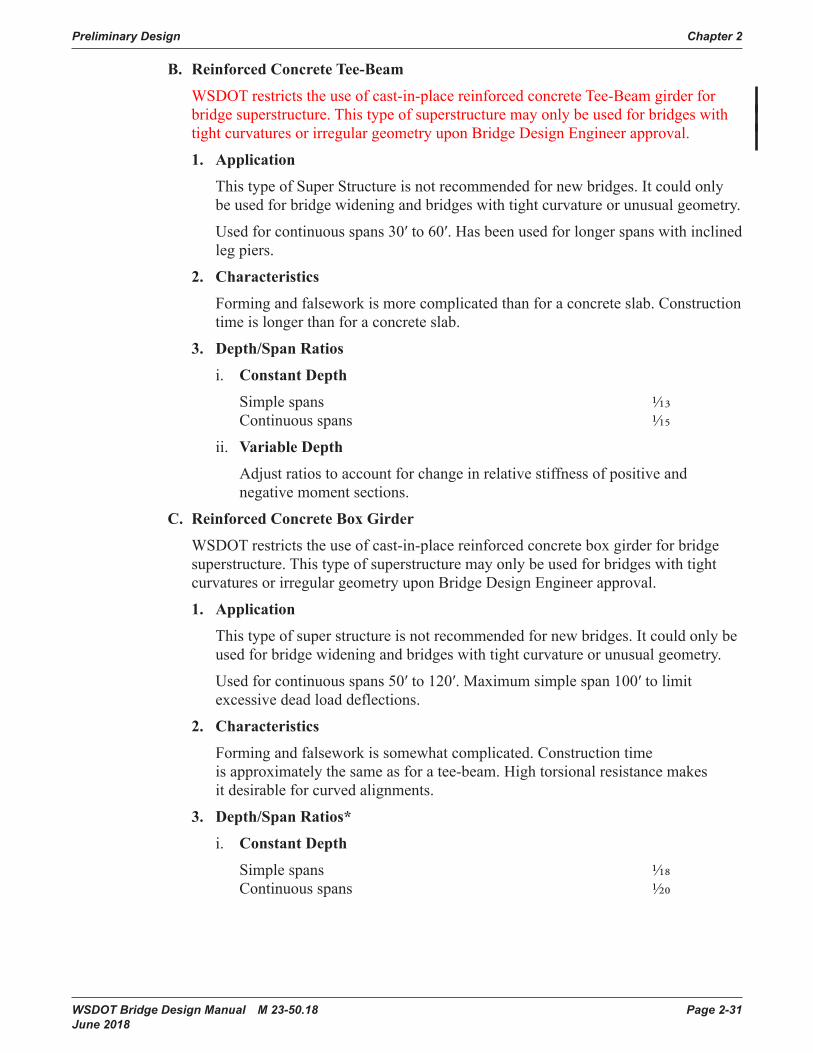
Preliminary Design Chapter 2
WSDOT Bridge Design Manual M 23-50.18 Page 2-31 June 2018
B. Reinforced Concrete Tee-Beam
WSDOT restricts the use of cast-in-place reinforced concrete Tee-Beam girder for bridge superstructure. This type of superstructure may only be used for bridges with tight curvatures or irregular geometry upon Bridge Design Engineer approval.
1. Application
This type of Super Structure is not recommended for new bridges. It could only be used for bridge widening and bridges with tight curvature or unusual geometry.
Used for continuous spans 30′ to 60′. Has been used for longer spans with inclined leg piers.
2. Characteristics
Forming and falsework is more complicated than for a concrete slab. Construction time is longer than for a concrete slab.
3. Depth/Span Ratios
i. Constant Depth
Simple spans 1/13 Continuous spans 1/15
ii. Variable Depth
Adjust ratios to account for change in relative stiffness of positive and negative moment sections.
C. Reinforced Concrete Box Girder
WSDOT restricts the use of cast-in-place reinforced concrete box girder for bridge superstructure. This type of superstructure may only be used for bridges with tight curvatures or irregular geometry upon Bridge Design Engineer approval.
1. Application
This type of super structure is not recommended for new bridges. It could only be used for bridge widening and bridges with tight curvature or unusual geometry.
Used for continuous spans 50′ to 120′. Maximum simple span 100′ to limit excessive dead load deflections.
2. Characteristics
Forming and falsework is somewhat complicated. Construction time is approximately the same as for a tee-beam. High torsional resistance makes it desirable for curved alignments.
3. Depth/Span Ratios*
i. Constant Depth
Simple spans 1/18 Continuous spans 1/20

Chapter 2 Preliminary Design
Page 2-32 WSDOT Bridge Design Manual M 23-50.18 June 2018
ii. Variable Depth
Adjust ratios to account for change in relative stiffness of positive and negative moment sections.
*If the configuration of the exterior web is sloped and curved, a larger depth/span ratio may be necessary.
D. Post-tensioned Concrete Box Girder
1. Application
Normally used for continuous spans longer than 120′ or simple spans longer than 100′. Should be considered for shorter spans if a shallower structure depth is needed.
2. Characteristics
Construction time is somewhat longer due to post-tensioning operations. High torsional resistance makes it desirable for curved alignments.
3. Depth/Span Ratios*
i. Constant Depth
Simple spans 1/20.5 Continuous spans 1/25
ii. Variable Depth
Two span structures
At Center of span 1/25 At Intermediate pier 1/12.5 Multi-span structures At Center of span 1/36 At Intermediate pier 1/18
*If the configuration of the exterior web is sloped and curved, a larger depth/span ratio may be necessary.
E. Prestressed Concrete Girder Sections
1. Application
Local precast fabricators have several standard forms available for precast concrete sections based on the WSDOT standard girder series. These are versatile enough to cover a wide variety of span lengths.
WSDOT standard girders are:
a. WF100G, WF95G, WF83G, WF74G, WF58G, WF50G, WF42G, WF36G, W74G, W58G, W50G, and W42G precast, prestressed concrete I-girders requiring a cast-in-place concrete bridge deck used for spans less than 200′. The number (eg. 95) specifies the girder depth in inches.
WF95PTG, WF83PTG and WF74PTG post-tensioned, precast segmental I-girders with cast-in-place concrete bridge deck use for simple span up to 230′, and continuous span up to 250′ with continuous post-tensioning over the intermediate piers.

Preliminary Design Chapter 2
WSDOT Bridge Design Manual M 23-50.18 Page 2-33 June 2018
b. U**G* and UF**G* precast, prestressed concrete tub girders requiring a cast-in-place concrete bridge deck are used for spans less than 140′. “U” specifies webs without flanges, “UF” specifies webs with flanges, ** specifies the girder depth in inches, and * specifies the bottom flange width in feet. U**G* girders have been precast as shallow as 26″.
Post-tensioned, precast, prestressed tub girders with cast-in-place concrete bridge deck are used for simple span up to 160′ and continuous span up to 200′.
c. W65DG, W53DG, W41DG, and W35DG precast, prestressed concrete decked bulb tee girders requiring an 1 ½” minimum HMA overlay roadway surface used for span less than 150′, with the Average Daily Truck limitation of 30,000 or less.
d. W62BTG, W38BTG, and W32BTG precast, prestressed concrete bulb tee girders requiring a cast-in-place concrete deck for simple spans up to 130′.
e. 12-inch, 18-inch, 26-inch, 30-inch, and 36-inch precast, prestressed slabs requiring 5″ minimum cast-in-place slab used for spans less than 100′.
f. 26-inch precast, prestressed ribbed girder, deck double tee, used for span less than 60′, and double tee members requiring an HMA overlay roadway surface used for span less than 40′.
g. WF36TDG, WF42TDG, WF50TDG, WF58TDG, WF66TDG, WF74TDG, WF83TDG, WF95TDG, and WF100TDG precast, prestressed concrete wide flange girders requiring a 5” minimum cast in place slab for simple spans up to 225’.
h. WF39DG, WF45DG, WF53DG, WF61DG, WF69DG, WF77DG, WF86DG, WF98DG, and WF103DG precast, prestressed concrete wide flange girders requiring an 1 ½” minimum Modified Conc. or 3 inch minimum HMA overlay roadway surface used for span less than 195′, with the Average Daily Truck limitation of 30,000 or less.
2. Characteristics
Superstructure design is quick for pre-tensioned girders with proven user-friendly software (PGSuper, PGSplice, and QConBridge)
Construction details and forming are fairly simple. Construction time is less than for a cast-in-place bridge. Little or no falsework is required. Falsework over traffic is usually not required; construction time over existing traffic is reduced.
Precast girders usually require that the bridge roadway superelevation transitions begin and end at or near piers; location of piers should consider this. The Region may be requested to adjust these transition points if possible.
Fully reinforced, composite 8 inch cast-in-place deck slabs continuous over interior piers or reinforced 5 inch cast-in-place deck slabs continuous over interior piers have been used with e. and f.

Chapter 2 Preliminary Design
Page 2-34 WSDOT Bridge Design Manual M 23-50.18 June 2018
F. Composite Steel Plate Girder
1. Application
Used for simple spans up to 260′ and for continuous spans from 120′ to 400′. Relatively low dead load when compared to a concrete superstructure makes this bridge type an asset in areas where foundation materials are poor.
2. Characteristics
Construction details and forming are fairly simple Construction time is comparatively short. Shipping and erecting of large sections must be reviewed. Cost of maintenance is higher than for concrete bridges. Current cost information should be considered because of changing steel market conditions.
3. Depth/Span Ratios
i. Constant Depth
Simple spans 1/22 Continuous spans 1/25
ii. Variable Depth
@ Center of span 1/40 @ Intermediate pier 1/20
G. Composite Steel Box Girder
1. Use
Used for simple spans up to 260′ and for continuous spans from 120′ to 400′. Relatively low dead load when compared to a concrete superstructure makes this bridge type an asset in areas where foundation materials are poor.
Inside clear height of less than 5 feet shall not be used because reasonable inspection access cannot be provided.
2. Characteristics
Construction details and forming are more difficult than for a steel plate girder. Shipping and erecting of large sections must be reviewed. Current cost information should be considered because of changing steel market conditions.
3. Depth/Span Ratios
i. Constant Depth
Simple spans 1/22 Continuous spans 1/25
ii. Variable Depth
At Center of span 1/40 At Intermediate pier 1/20
Note: Sloping webs are not used on box girders of variable depth.

Preliminary Design Chapter 2
WSDOT Bridge Design Manual M 23-50.18 Page 2-35 June 2018
H. Steel Truss
1. Application
Used for simple spans up to 300′ and for continuous spans up to 1,200′. Used where vertical clearance requirements dictate a shallow superstructure and long spans or where terrain dictates long spans and construction by cantilever method.
2. Characteristics
Construction details are numerous and can be complex. Cantilever construction method can facilitate construction over inaccessible areas. Through trusses are discouraged because of the resulting restricted horizontal and vertical clearances for the roadway.
3. Depth/Span Ratios
a. Simple spans 1/6
b. Continuous spans
@ Center of span 1/18 @ Intermediate pier 1/9
I. Segmental Concrete Box Girder
1. Application
Used for continuous spans from 200′ to 700′. Used where site dictates long spans and construction by cantilever method.
2. Characteristics
Use of travelers for the form apparatus facilitates the cantilever construction method enabling long-span construction without falsework. Precast concrete segments may be used. Tight geometric control is required during construction to ensure proper alignment.
3. Depth/Span Ratios
Variable depth At Center of span 1/50 At Intermediate pier 1/20
J. Railroad Bridges
1. Use
For railway over highway grade separations, most railroad companies prefer simple span steel construction. This is to simplify repair and reconstruction in the event of derailment or some other damage to the structure.
2. Characteristics
The heavier loads of the railroad live load require deeper and stiffer members than for highway bridges. Through girders can be used to reduce overall structure depth if the railroad concurs. Piers should be normal to the railroad to eliminate skew loading effects.

Chapter 2 Preliminary Design
Page 2-36 WSDOT Bridge Design Manual M 23-50.18 June 2018
3. Depth/Span Ratios
Constant depth Simple spans 1/12 Continuous two span 1/14 Continuous multi-span 1/15
K. Timber
1. Use
Generally used for spans under 40′. WSDOT restricts the use of timber girders for bridge superstructures to non-vehicle use bridges or temporary bridges.
2. Characteristics
Excellent for short-term duration as for a detour. Simple design and details.
3. Depth/Span Ratios
Constant depth Simple span – Timber beam 1/10 Simple span – Glulam beam 1/12 Continuous spans 1/14
L. Other
Bridge types such as cable-stayed, suspension, arch, tied arch, and floating bridges have special and limited applications. The use of these bridge types is generally dictated by site conditions. Preliminary design studies will generally be done when these types of structures are considered.
2.4.2 Wall TypesRetaining walls, wingwalls, curtain walls, and tall closed abutment walls may be used where required to shorten spans or superstructure length or to reduce the width of approach fills. The process of selecting a type of retaining wall should economically satisfy structural, functional, and aesthetic requirements and other considerations relevant to a specific site. A detailed listing of the common wall types and their characteristics can be found in Chapter 8.
2.4.3 Buried Structure TypesTunnel and Culverts may be used where required in accordance to specific site conditions. The process of selecting a type of buried structure should economically satisfy structural, functional, and aesthetic requirements and other considerations relevant to a specific site. A detailed listing of the common types and their characteristics can be found in Chapter 8.

Preliminary Design Chapter 2
WSDOT Bridge Design Manual M 23-50.18 Page 2-37 June 2018
2.5 Aesthetic Considerations2.5.1 General Visual Impact
Bridge, retaining walls and noise walls have a strong visual impact in any landscape. Steps must be taken to assure that even the most basic structure will complement rather than detract from its surroundings. The EIS and bridge site data submitted by the Region should each contain a discussion on the aesthetic importance of the project site. This commentary, together with submitted video and photographs, will help the designer determine the appropriate structure type.
The State Bridge and Structures Architect should be contacted early in the preliminary bridge plan process for input on aesthetics. Normally, a visit to the bridge site with the State Bridge and Structures Architect and Region design personnel should be made.
Aesthetics is a very subjective element that must be factored into the design process in the otherwise very quantitative field of structural engineering. Bridges that are structurally efficient using the least material possible are generally visually well proportioned. However, the details such as pier walls, columns, and crossbeams require special attention to ensure a structure that will enhance the general vicinity.
For large projects incorporating several to many bridges and retaining walls, an architectural theme is frequently developed to bring consistency in structure type, details, and architectural appointments. The preliminary plan designer shall work with the State Bridge and Structures Architect to implement the theme.
2.5.2 End PiersA. Wingwalls
The size and exposure of the wingwall at the end pier should balance, visually, with the depth and type of superstructure used. For example, a prestressed girder structure fits best visually with a 15′ wingwall (or curtain wall/retaining wall). However, there are instances where a 20′ wingwall (or curtain wall/retaining wall) may be used with a prestressed girder (maximizing a span in a remote area, for example or with deep girders where they are proportionally better in appearance). The use of a 20′ wingwall shall be approved by the Bridge Design Engineer and the State Bridge and Structures Architect.
It is less expensive for bridges of greater than 40′ of overall width to be designed with wingwalls (or curtain wall/retaining wall) than to use a longer superstructure.
B. Retaining Walls
For structures at sites where profile, right of way, and alignment dictate the use of high exposed wall-type abutments for the end piers, retaining walls that flank the approach roadway can be used to retain the roadway fill and reduce the overall structure length. Stepped walls are often used to break up the height, and allow for landscape planting. A curtain wall runs between the bridge abutment and the heel of the abutment footing. In this way, the joint in the retaining wall stem can coincide with the joint between the abutment footing and the retaining wall footing. This simplifies design and provides a convenient breaking point between design responsibilities if the retaining walls happen to be the responsibility of the Region. The length shown for the curtain wall dimension is an estimated dimension based on experience and preliminary foundation assumptions. It can be revised under

Chapter 2 Preliminary Design
Page 2-38 WSDOT Bridge Design Manual M 23-50.18 June 2018
design to satisfy the intent of having the wall joint coincide with the end of the abutment footing.
C. Slope Protection
The Region is responsible for making initial recommendations regarding slope protection. It should be compatible with the site and should match what has been used at other bridges in the vicinity. The type selected shall be shown on the Preliminary Plan. It shall be noted on the “Not Included in Bridge Quantities” list.
D. Noise Walls
Approval of the State Bridge and Structures Architect is required for the final selection of noise wall appearance, finish, materials and configuration.
2.5.3 Intermediate PiersThe size, shape, and spacing of the intermediate pier elements must satisfy two criteria. They must be correctly sized and detailed to efficiently handle the structural loads required by the design and shaped to enhance the aesthetics of the structure.
The primary view of the pier must be considered. For structures that cross over another roadway, the primary view will be a section normal to the roadway. This may not always be the same view as shown on the Preliminary Plan as with a skewed structure, for example. This primary view should be the focus of the aesthetic review.
Tapers and flares on columns should be kept simple and structurally functional. Fabrication and constructability of the formwork of the pier must be kept in mind. Crossbeam ends should be carefully reviewed. Skewed bridges and bridges with steep profile grades or those in sharp vertical curves will require special attention to detail.
Column spacing should not be so small as to create a cluttered look. Column spacing should be proportioned to maintain a reasonable crossbeam span balance.
2.5.4 Barrier and Wall Surface TreatmentsA. Plain Surface Finish
This finish will normally be used on structures that do not have a high degree of visibility or where existing conditions warrant. A bridge in a remote area or a bridge among several existing bridges all having a plain finish would be examples.
B. Formliner Finishes
These finishes are the most common and an easy way to add a decorative texture to a structure. Variations on this type of finish can be used for special cases. The specific areas to receive this finish should be reviewed with the State Bridge and Structures Architect.
C. Pigmented Sealer
The use of a pigmented sealer is used to control graffiti and can also be an aesthetic enhancement. Most commonly it is always used in urban areas. The selection should be reviewed with the Bridge Architect and the Region.

Preliminary Design Chapter 2
WSDOT Bridge Design Manual M 23-50.18 Page 2-39 June 2018
D. Architectural Details
Rustication grooves, relief panels, pilasters, and decorative finishes may visually improve appearance at transitions between different structure types such as cast-in-place abutments to structural earth retaining walls. Contact the State Bridge and Structures Architect for guidance.
In special circumstances custom designs may be provided. Designs rising to the level of art shall be subject to the procedures outlined in the Design Manual M 22-01
2.5.5 SuperstructureThe horizontal elements of the bridge are perhaps the strongest features. The sizing of the structure depth based on the span/depth ratios in Section 2.4.1, will generally produce a balanced relationship.
Designs rising to the level of "Art" shall be subject to the procedures outlined in the Design Manual M 22-01.
Haunches or rounding of girders at the piers can enhance the structure’s appearance. The use of such features should be kept within reason considering fabrication of materials and construction of formwork. The amount of haunch should be carefully reviewed for overall balance from the primary viewing perspective. Haunches are not limited to cast-in-place superstructures, but may be used in special cases on precast, prestressed I girders. They require job-specific forms which increase cost, and standard design software is not directly applicable.
The slab overhang dimension should approach that used for the structure depth. This dimension should be balanced between what looks good for aesthetics and what is possible with a reasonable slab thickness and reinforcement.
For box girders, the exterior webs can be sloped, but vertical webs are preferred. The amount of slope should not exceed l½: l for structural reasons, and should be limited to 4:1 if sloped webs are desired. Sloped webs should only be used in locations of high aesthetic impact.
When using precast, prestressed girders, all spans shall be the same series, unless approved otherwise by the Bridge Design Engineer.

Chapter 2 Preliminary Design
Page 2-40 WSDOT Bridge Design Manual M 23-50.18 June 2018
2.6 Miscellaneous2.6.1 Structure Costs
See Section 12.3 for preparing cost estimates for preliminary bridge design.
2.6.2 Handling and Shipping Precast Members and Steel BeamsBridges utilizing precast concrete beams or steel beams need to have their access routes checked and sites reviewed to be certain that the beams can be transported to the site. It must also be determined that they can be erected once they reach the site.
Both the size and the weight of the beams must be checked. Likely routes to the site must be adequate to handle the truck and trailer hauling the beams. Avoid narrow roads with sharp turns, steep grades, and/or load-rated bridges, which may prevent the beams from reaching the site. The Bridge Preservation Office should be consulted for limitations on hauling lengths and weights.
Generally 252 kips is the maximum weight of a girder that may be hauled by truck.
The site should be reviewed for adequate space for the contractor to set up the cranes and equipment necessary to pick up and place the girders. The reach and boom angle should be checked and should accommodate standard cranes.
2.6.3 Salvage of MaterialsWhen a bridge is being replaced or widened, the material being removed should be reviewed for anything that WSDOT may want to salvage. Items such as aluminum rail, luminaire poles, sign structures, and steel beams should be identified for possible salvage. The Region should be asked if such items are to be salvaged since they will be responsible for storage and inventory of these items.

Preliminary Design Chapter 2
WSDOT Bridge Design Manual M 23-50.18 Page 2-41 June 2018
2.7 WSDOT Standards for Highway Bridges2.7.1 Design Elements
The following are standard design elements for bridges carrying highway traffic. They are meant to provide a generic base for consistent, clean looking bridges, and to reduce design and construction costs. Modification of some elements may be required, depending on site conditions. This should be determined on a case-by-case basis during the preliminary plan stage of the design process.
A. General
Fractured Fin Finish shall be used on the exterior face of the traffic barrier. All other surfaces shall be Plain Surface Finish.
Exposed faces of wingwalls, columns, and abutments shall be vertical. The exterior face of the traffic barrier and the end of the intermediate pier crossbeam and diaphragm shall have a 1:12 backslope.
B. Substructure
End piers use the following details:
15′ wingwalls with prestressed girders up to 74″ in depth or a combination of curtain wall/retaining walls.
Stub abutment wall with vertical face. Footing elevation, pile type (if required), and setback dimension are determined from recommendations in the Materials Laboratory Geotechnical Services Branch Geotechnical Report.
Intermediate piers use the following details:
“Semi-raised” Crossbeams – The crossbeam below the girders is designed for the girder and slab dead load, and construction loads. The crossbeam and the diaphragm together are designed for all live loads and composite dead loads. The minimum depth of the crossbeam shall be 3′.
“Raised” Crossbeams – The crossbeam is at the same level as the girders are designed for all dead and live loads.
Round Columns – Columns shall be 3′ to 6′ inch diameter. Dimensions are constant full height with no tapers. Bridges with roadway widths of 40′ or less will generally be single column piers. Bridges with roadway widths of greater the 40′ shall have two or more columns, following the criteria established in Section 2.3.1.H. Oval or rectangular column may be used if required for structural performance or bridge visual.
C. Superstructure
Concrete Slab – 7½ inch minimum thickness with epoxy coated steel reinforcing bars in general with 5 inch minimum thickness for deck girders and 8 inch minimum thickness for steel girders.
Prestressed Girders – Girder spacing will vary depending on roadway width and span length. The slab overhang dimension is approximately half of the girder spacing. Girder spacing typically ranges between 6′ and 12′.
Intermediate Diaphragms – Locate in accordance with Table 5.6.2-1 and Section 5.6.4.C. Provide full or partial depth in accordance with Section 5.6.4.C.4.

Chapter 2 Preliminary Design
Page 2-42 WSDOT Bridge Design Manual M 23-50.18 June 2018
End Diaphragms – “End Wall on Girder” type.
Traffic Barrier – Use 3’-6” high “F-shape” or Single-sloped barrier to meet worker fall protection requirements.
Fixed Diaphragm at Inter. Piers – Full or partial width of crossbeam between girders and outside of the exterior girders.
Hinged Diaphragm at Inter. Piers – Partial width of crossbeam between girders. Sloped curtain panel full width of crossbeam outside of exterior girders, fixed to ends of crossbeam.
BP Rail – 3′–6″ overall height for pedestrian traffic. 4′–6″ overall height for bicycle traffic.
Sidewalk – 6-inch height at curb line. Transverse slope of -0.02 feet per foot towards the curb line.
Sidewalk barrier – Inside face is vertical. Outside face slopes 1:12 outward.
Expansion Joints – refer to table in Section 9.1.1 for guidance regarding maximum bridge superstructure length beyond which the use of either intermediate expansion joints or modular expansion joints at the ends is required.
D. Examples
Appendices 2.3-A2-1 and 2.7-A1-1 detail the standard design elements of a standard highway bridge.
The following bridges are good examples of a standard highway bridge. However, they do have some modifications to the standard.
SR 17 Undercrossing 395/110 Contract 3785 Mullenix Road Overcrossing 16/203E&W Contract 4143
2.7.2 Detailing the Preliminary PlanThe Bridge or Culvert Preliminary Plan is used and reviewed by the Bridge and Structures Office or consultant who will do the structural design, Region designers and managers, Geotechnical engineers, Hydraulics engineers, Program managers, FHWA engineers and local agency designers and managers. It sometimes is used in public presentation of projects. With such visibility it is important that it's detailing is clear, complete, professional, and attractive. The designer, detailer, and checker shall strive for completeness and consistency in information, layout, line style, and fonts. Appendix B contains examples of Preliminary Plans following time-proven format that may be helpful. See also Chapter 11.
Typical sheet layout is as follows:
1. Plan and Elevation views. (This sheet ultimately becomes the Layout sheet of the design plan set)
2. Typical Section including details of stage construction.
Superelevation diagrams, tables of existing elevations, Notes to Region, and other miscellaneous details as required shall go on Sheet 2, 3, or 4, as many as required. See also the Preliminary Plan Checklist for details, dimensions, and notes typically required. The completed plan sheets shall be reviewed for consistency by the Preliminary Plans Detailing Specialist.

Preliminary Design Chapter 2
WSDOT Bridge Design Manual M 23-50.18 Page 2-43 June 2018
2.7.3 Bridge Design Minimum RequirementsThe following requirements defines WSDOT policy for all bridge designs regard-less of the contracting methods (DBB, DB, GCCM, etc.). The following items are required for all WSDOT bridges and structures and cannot be negotiated or compromised for Practical Design purposes or alternative technical concepts (ATC) used in Design-Build projects:
1. In general, black rebar cannot be substituted for epoxy coated rebar in structures. Specifically, black rebar cannot be substituted for epoxy rebar in bridge decks.
2. Prestressed girder bridges must be designed for zero tension at service limit state, and continuous prestressed girders must be designed as simple spans for both dead an live loads. The same girder depth must be used for multiple spans.
3. Deletion of bridge approach slabs is not allowed.
4. Deletion of intermediate diaphragms is not allowed for prestressed girder bridges.
5. Stay-In-Place metal forms (SIP) are not allowed for bridges.

Chapter 2 Preliminary Design
Page 2-44 WSDOT Bridge Design Manual M 23-50.18 June 2018
2.8 Bridge Security2.8.1 General
Security based bridge design and its direct correlation to modern social issues is addressed in this section. Criminal activity, illegal encampments, graffiti, hindrance to economic development and public eyesore create unwanted expensive. They also pose safety hazard for State Maintenance and Operations practices. The issue exists in urban areas as well as rural and recreational locales.
Bridges are dominant structures in landscapes. They are held to a higher standard of design due to their influence on communities, where economic and social settings are affected by their quality. Initial project cost savings may quickly be overshadowed by increased externalized costs. These externalized costs are born by local municipalities and businesses as well as other departments within WSDOT.
WSDOT bridge inspectors are required to inspect all bridges at least once every 24 months. The presence of the illegal encampments, as well as garbage, hypodermic needles, and feces often makes it impossible to do a close, hands-on inspection of the abutments and bearings of bridges. The Bridge Preservation Office has requested that maintenance clean up transient camps when it becomes difficult or impossible to do an adequate inspection of the bridges. Campfires set by the homeless have also caused damage to bridges.
Bridge Maintenance Crews also face the same difficulty when they need to do repair work on bridges in the urban area. Clean up requires (per law) posting the bridge seventy-two hours prior to any work. Material picked up is tagged, bagged, and stored for retrieval. Often the offenders are back the next day.
2.8.2 DesignDesign is determined on a case by case basis using two strategies. These strategies are universally accepted best practices. The first, Crime Prevention through Environmental Design (CPTED), is a multi-disciplinary approach to deterring criminal behavior. The second, Context Sensitive Solutions (CSS), is also multi-disciplinary and focuses on project development methods. Multi-disciplinary teams consist of engineers and architects but may include law enforcement, local businesses, social service providers, and psychologists.
A. CPTED principals are based upon the theory that the proper design and effective use of the built environment can reduce crime, reduce the fear of crime, and improve the quality of life. Built environment implementations of CPTED seek to dissuade offenders from committing crimes by manipulating the built environment in which those crimes proceed from or occur. The six main concepts are territoriality, surveillance, access control, image/maintenance, activity support and target hardening. Applying all of these strategies is key when preventing crime in any neighborhood or right-of-way.

Preliminary Design Chapter 2
WSDOT Bridge Design Manual M 23-50.18 Page 2-45 June 2018
Natural surveillance and access control strategies limit the opportunity for crime. Territorial reinforcement promotes social control through a variety of measures. These may include enhanced aesthetics or public art. Image/maintenance and activity support provide the community with reassurance and the ability to stop crime by themselves. Target hardening strategies may involve fencing or concrete enclosures or they may include all techniques to resolve crime or chronic trespass into one final step.
B. WSDOT implements FHWA’s CSS design development principles through Executive Order E 1028. The CSS methods require designers to consider the physical, economic, and social setting of a project. Stakeholder’s interests are to be accounted for; including area residents and business owners.
2.8.3 Design CriteriaNew bridges need to address design for the environment by basic criteria:• Slopes under bridges need to be steep slope, and hardened with something like solid
concrete so that flat areas cannot be carved into the hillside. Flat areas under bridge superstructures attract inappropriate uses and should be omitted.
• Illegal urban campers have been known to build shelters between the concrete girders. Abutment walls need to be high enough that they deny access to the superstructure elements. When it is not feasible to design for deterrence the sites need to be hardened with fencing buried several feet into the soil or with solid concrete walls. See Figures 2.8.3-1 and 2.8.3-2 for high security fence and concrete wall examples.
• Regular chain link is easy cut, therefore stouter material needs to be specified.• Landscape design should coordinate with region or headquarters landscape architects.
Areas need to be visible to law enforcement.
Figure 2.8.3-1 Bent Type Abutment Plan
Figure 2.8.3-1
CONCRETE FASCIA WITHINSPECTION DOOR.
BRIDGE ABUTMENT END PIERCONFIGURATION WITH COLUMNS.
APPROACH EMBANKMENT WALL

Chapter 2 Preliminary Design
Page 2-46 WSDOT Bridge Design Manual M 23-50.18 June 2018
Figu
re 2
.8.3
-2
POST F
OUNDATION (
TYP.)
CONTINUOUS C
ONC.
CURB (
TYP.)
RAIL (
TYP.)
ABUTMENT F
OUNDTAION
POST (
TYP.)
BRIDGE S
ECURITY F
ENCE
IN F
RONT O
F A
BUTMENT
FINISHED G
ROUND LINE
BRIDGE S
ECURITY F
ENCE
ON T
OP O
F A
BUTMENT
1" G
AP (
TYP. AT
HORIZONTAL ELE
MENTS)
½" GAP (
TYP. AT
VERTICAL ELE
MENTS)
GALV
. STEEL WELD
ED
WIRE M
ESH F
ABRIC
BRIDGE S
ECURITY F
ENCE
RETURN T
O A
BUTMENT
SEE D
ETAIL
1
BOTTOM O
FGIRDER F
LANGE
DETAIL
1
PRY R
ESISTANT E
LEMENT W
ITH
DIRECT C
ONNECTION T
O R
AIL
RAIL
POST
GALV
. STEEL WELD
ED
WIRE M
ESH F
ABRIC

Preliminary Design Chapter 2
WSDOT Bridge Design Manual M 23-50.18 Page 2-47 June 2018
2.9 Bridge Standard Drawings2-B-1 Bridge Preliminary Plan Example - Precast Slab Bridge
2-B-2 Bridge Preliminary Plan Example - Temporary Bridge
2-B-3 Bridge Preliminary Plan Example - Bridge Cross Sections
2-B-4 Bridge Preliminary Plan Example - Precast Tub Girder Bridge
2-B-5 Bridge Preliminary Plan Example - Bridge Cross Section
2-B-6 Bridge Preliminary Plan Example - Roadway Data
2-B-7 Bridge Preliminary Plan Example - Precast Girder Bridge Widening
2-B-8 Bridge Preliminary Plan Example - Widened Bridge Cross Section
2-B-9 Bridge Preliminary Plan Example - Existing Roadway Survey Data
2.3-A1 Bridge Stage Construction Comparison
2.3-A2 Bridge Redundancy Criteria
2.4-A1 Bridge Selection Guide
2.7-A1 Standard Superstructure Elements

Chapter 2 Preliminary Design
Page 2-48 WSDOT Bridge Design Manual M 23-50.18 June 2018
2.10 AppendicesAppendix 2.2-A1 Bridge Site Data General
Appendix 2.2-A2 Bridge Site Data Rehabilitation
Appendix 2.2-A3 Bridge Site Data Stream Crossing
Appendix 2.2-A4 Preliminary Plan Checklist
Appendix 2.2-A5 Request For Preliminary Geotechnical Information
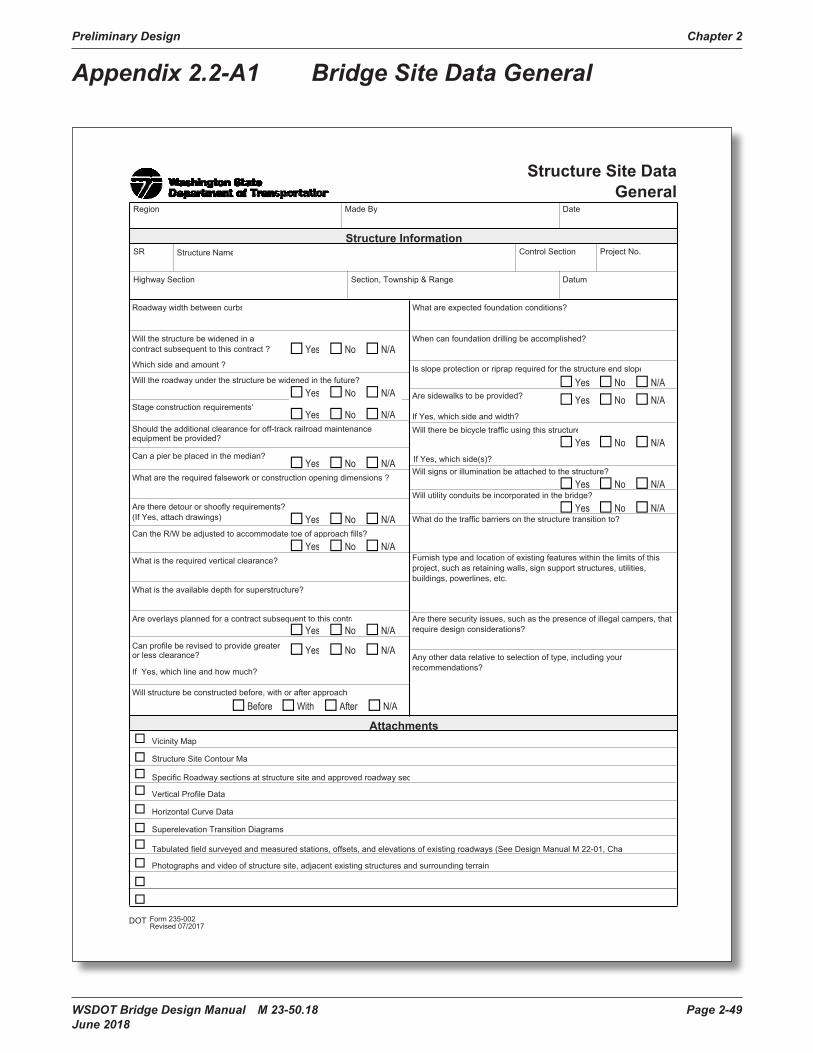
Preliminary Design Chapter 2
WSDOT Bridge Design Manual M 23-50.18 Page 2-49 June 2018
Appendix 2.2-A1 Bridge Site Data General
Yes No N/A
Yes No N/A
Yes No N/A
Yes No N/A
Yes No N/A
Yes No N/A
Yes No N/A
Yes No N/A
Yes No N/A
Yes No N/A
Before With After N/A
Yes No N/AYes No N/A
Yes No N/A
Structure Site DataGeneral
Vicinity Map
Structure Site Contour Map
Specific Roadway sections at structure site and approved roadway sec
Vertical Profile Data
Horizontal Curve Data
Superelevation Transition Diagrams
Photographs and video of structure site, adjacent existing structures and surrounding terrain
Attachments
Roadway width between curbs
Will the structure be widened in acontract subsequent to this contract ?
Which side and amount ?
Can a pier be placed in the median?
What is the required vertical clearance?
Can profile be revised to provide greateror less clearance?
If Yes, which line and how much?
Yes No N/A
Yes No N/A
Yes No N/A
Are sidewalks to be provided?
If Yes, which side and width?Will there be bicycle traffic using this structure
Can the R/W be adjusted to accommodate toe of approach fills?
What is the available depth for superstructure?
Are overlays planned for a contract subsequent to this contra
Will signs or illumination be attached to the structure?
Yes No N/A
Yes No N/A
Yes No N/A
Yes No N/A
Yes No N/A
SR Control Section Project No.
Region Made By Date
Structure InformationStructure Name
Highway Section Section, Township & Range Datum
Should the additional clearance for off-track railroad maintenanceequipment be provided?
Will the roadway under the structure be widened in the future?
Stage construction requirements?
Are there detour or shoofly requirements?(If Yes, attach drawings) Yes No N/A
What are the required falsework or construction opening dimensions ?
Yes No N/A
Will structure be constructed before, with or after approach f
Before With After N/A
When can foundation drilling be accomplished?
What are expected foundation conditions?
Furnish type and location of existing features within the limits of thisproject, such as retaining walls, sign support structures, utilities,buildings, powerlines, etc.
Is slope protection or riprap required for the structure end slope
Yes No N/A
Any other data relative to selection of type, including yourrecommendations?
Yes No N/A
Will utility conduits be incorporated in the bridge?Yes No N/A
What do the traffic barriers on the structure transition to?
Tabulated field surveyed and measured stations, offsets, and elevations of existing roadways (See Design Manual M 22-01, Cha
Are there security issues, such as the presence of illegal campers, thatrequire design considerations?
If Yes, which side(s)?
DOT Form 235-002Revised 07/2017

Chapter 2 Preliminary Design
Page 2-50 WSDOT Bridge Design Manual M 23-50.18 June 2018
Appendix 2.2-A2 Bridge Site Data Rehabilitation
Yes No
Yes No
Yes No
Yes No
Right of
Thickness
Roadway deck elevations at curb lines (10-foot spacing)
Existing drains to be plugged, modified, moved, other?
Proposed overlay (HMA, HMA w /membrame, MC, epoxy) Thickness
Yes NoIs traffic barrier/railing to be modified?
Existing rail type
Proposed rail replacement type
Yes NoWill terminal design “F” be required?
Yes NoWill utilities be placed in the new barrier?
Existing roadway width, curb to curb CLLeft of CL
Proposed roadway width, curb to curb CLLeft of Right of CL
Existing wearing surface (concrete, HMA, HMA w /membrane, MC, epoxy, other)
Will the structure be overlayed with or after rail replacement? With Rail Replacement After Rail Replacement
Condition of existing expansion joints
Yes NoExisting expansion joints watertight?
Inch Inch Inch
Estimate structure temperature at time of expansion joint measurement
Type of existing expansion joint
Describe damage, if any, to existing expansion joints
Existing Vertical Clearance
Video tape of project
Photographs of existing expansion joints.
Measure width of existing expansion joint, normal to skew.CL@@ curb line @ curb lineroadway
Sketch indicating points at which expansion joint width was measured.
Proposed Vertical Clearance (at curb lines of traffic barrier)
Attachments
Existing deck chloride and delamination data.
Structure Information
Structure Site Data Rehabilitation
SR Control Section Project No.
Region Made By Date
Structure Name
Highway Section Section, Township & Range Vertical Datum
DOT Form 235-002ARevised 07/2017

Preliminary Design Chapter 2
WSDOT Bridge Design Manual M 23-50.18 Page 2-51 June 2018
Appendix 2.2-A3 Bridge Site Data Stream Crossing
Amount and Character of Drift
Structure Information
Structure Site DataStream Crossings
FinesSand
GravelCobble
Boulder
SR Control Section Project No.
Region Made By Date
Name of Stream Tributary of
Elevation of W.S.
Other Data Relative to Selection of Type and Design of Structure, Including your Recommendations (e.g., requirementsof riprap, permission of piers in channel.)
Manning’s “N” Value (Est.)
Highway Alignment and Profile (refer to base map and profiles)
Streambed: Profile and Cross Sections defining bankfull width and bank shelf widths and slopes (See Sect. 710.03WSDOT Design Manual)
Photographs
Character of Stream Banks (e.g., rock, silt.) / Location of Solid Rock
Structure Name
Highway Section Section, Township & Range Datum (e.g. NGVD29, NAVD88, USGS)
Site Contour Map (See Sect. 710.04 WSDOT Design Manual)
(@ Date/Time of survey)
Attachments
Flow (CFS) WSE (ft) Flow (CFS) WSE (ft)
Streambed Material2-YR
100-YR500-YR
2-YR100-YR500-YR
MLLWMHHW
Non-Tidal Tidal
DOT Form 235-001Revised 07/2017

Chapter 2 Preliminary Design
Page 2-52 WSDOT Bridge Design Manual M 23-50.18 June 2018
Appendix 2.2-A4 Preliminary Plan ChecklistProject __________________ SR ______ Prelim . Plan by ____________ Check by _____ Date_______
Plan
Survey Lines and Station TicksSurvey Line Intersection AnglesSurvey Line Intersection StationsSurvey Line BearingsRoadway and Median WidthsLane and Shoulder WidthsSidewalk WidthConnection/Widening for Guardrail/BarrierProfile Grade and Pivot PointRoadway Superelevation Rate (if constant)Lane Taper and Channelization DataTraffic ArrowsMileage to Junctions along MainlineBack to Back of Pavement SeatsSpan LengthsLengths of Walls next to/part of BridgePier Skew AngleBridge Drains, or Inlets off BridgeExisting drainage structuresExisting utilities Type, Size, and LocationNew utilities - Type, Size, and LocationLuminaires, Junction Boxes, ConduitsBridge mounted Signs and SupportsContoursTop of Cut, Toe of Fill Bottom of DitchesTest Holes (if available)Riprap LimitsStream Flow ArrowR/W Lines and/or Easement LinesPoints of Minimum Vertical ClearanceHorizontal ClearanceExist . Bridge No . (to be removed, widened)Section, Township, RangeCity or TownNorth ArrowSR NumberBearing of Piers, or note if radial
Miscellaneous
Structure TypeLive LoadingUndercrossing Alignment Profiles/Elevs .Superelevation DiagramsCurve DataRiprap DetailPlan Approval BlockNotes to RegionNames and SignaturesNot Included in Bridge Quantities ListInspection and Maintenance Access
Elevation
Full Length Reference Elevation LineExisting Ground Line x ft . Rt of Survey Line End Slope RateSlope Protection Pier Stations and Grade Elevations Profile Grade Vertical CurvesBP/Pedestrian RailBarrier/Wall Face TreatmentConstruction/Falsework OpeningsMinimum Vertical ClearancesWater Surface Elevations and Flow Data RiprapSeal Vent ElevationDatum Grade elevations shown are equal to …For Embankment details at bridge ends . . .Indicate F, H, or E at abutments and piers

Preliminary Design Chapter 2
WSDOT Bridge Design Manual M 23-50.18 Page 2-53 June 2018
Typical Section
Bridge Roadway WidthLane and Shoulder WidthsProfile Grade and Pivot PointSuperelevation RateSurvey LineOverlay Type and Depth Barrier Face Treatment Limits of Pigmented Sealer BP/Pedestrian Rail dimensions Stage Construction, Stage trafficLocations of Temporary Concrete BarrierClosure PourStructure Depth/Prestressed Girder TypeConduits/Utilities in bridge Substructure DimensionsBridge Inspection Lighting and Access
Left Margin
Job NumberBridge (before/with/after) Approach FillsStructure Depth/Prestressed Girder TypeDeck Protective SystemCoast Guard Permit Status (Requirement for all water crossing)Railroad Agreement StatusPoints of Minimum Vertical ClearanceCast-in-Place Concrete Strength
Right Margin
Control SectionProject NumberRegionHighway SectionSR NumberStructure Name

Chapter 2 Preliminary Design
Page 2-54 WSDOT Bridge Design Manual M 23-50.18 June 2018
Appendix 2.2-A5 Request For Preliminary Geotechnical Information
Date:Requested By:
Geotechnical Information Provided By:
Project Name:
Request for Preliminary StructureGeotechnical Information
Project Location:
End Pier Stations: Intermediate Pier Stations:
Permissible Embankment Slope: Seismic Acceleration Coefficient:
End Pier(s) Recommendation:
Approximate Dead Load: Approximate Live Load:
Furnish information on anticipated foundation type, pile or shaft sizes, permanent vs. temporary casing, expected pile orshaft lengths, special excavation, underground water table elevation and the need for seals/cofferdams:
Provide other Geotechnical information impacting structure's preliminary cost estimate:
Interior Pier(s) Recommendation (See information requested for end piers):
Approximate Dead Load: Approximate Live Load:
Liquefaction Issues. Indicate potential for liquefaction at the piers, anticipated depth of liquefaction, potential for lateralspread, and the need for soil remediation:
DOT Form 230-04507/2017

Preliminary Design Chapter 2
WSDOT Bridge Design Manual M 23-50.18 Page 2-55 June 2018
Not Included InStructure Quantities List
Environmental And Engineering Service CenterBridge and Structures Office
SR Job Number Project Title
Designed By Checked By Date Supervisor
Type of Structure
The following is a list of items for which the Bridge and Structures Office is relying on the Region to furnishplans, specifications and estimates.
1.
2.
3.
4.
5.
6.
7.
8.
9.
10.
11.
12.
13.
14.
15.
16.
17.
DOT Form 230-038Revised 07/2017

Chapter 2 Preliminary Design
Page 2-56 WSDOT Bridge Design Manual M 23-50.18 June 2018
2.99 References1. Federal Highway Administration (FHWA) publication Federal Aid Highway
Program Manual.
FHWA Order 5520.1 (dated December 24, 1990) contains the criteria pertaining to Type, Size, and Location studies.
Volume 6, Chapter 6, Section 2, Subsection 1, Attachment 1 (Transmittal 425) contains the criteria pertaining to railroad undercrossings and overcrossings.
2. WAC480-60 Railroad Companies - Clearances
3. American Railway Engineering and Maintenance Association (AREMA) Manual for Railroad Engineering. Note: This manual is used as the basic design and geometric criteria by all railroads. Use these criteria unless superseded by FHWA or WSDOT criteria.
4. WSDOT Design Manual M 22-01.
5. WSDOT Geotechnical Design Manual M 46-03.
6. WSDOT Hydraulics Manual M 23-03.
7. WSDOT Local Agency Guidelines M 36-63.
8. American Association of State Highway and Transportation Officials AASHTO LRFD Bridge Design Specification.
9. The Union Pacific Railroad “Guidelines for Design of Highway Separation Structures over Railroad (Overhead Grade Separation)”
10. WSDOT Context Sensitive Solutions Executive Order E 1028
11. Newman, O. Defensible Space: Crime Prevention Through Urban Design. New York: Macmillan. 1972.
12. Jacobs, Jane. The Death and Life of Great American Cities. New York: Random House. 1961.