bridge design aids, - caltrans · this pile shaft material
TRANSCRIPT

BRIDGE DESIGN AIDS MARCH 1990 12·0
Thefollowing pages ofBridge Design Aids, Section 12, have been reviewed in February 1990 and found 10 be valid and appropriate for continued use:
Pages Dace Ticle
12-30 thru 12-49 September 1986 Pile Shaft Design
These pages wilt-be updated from rime-to-time when significant changes in the technology occur.
/J J//~ . .<:::::J.:- -A,..«f~ /~D. Mancani
TPJ:rnkp

BRIDGE DESIGN AIDS September 19 86 12-30 ==:==============================================================
PILE SHAFT DESIGN
GENERAL
This pile shaft material <12-30 thru 12-49) replaces previously distributed literature concerning pile shaft design. The two design charts which estimate the depth to the point of effective fixity based on the Kocsis procedure, contained in the memorandum dated November 1984, have been replaced. These charts are no longer to be used.
After obtaining input from representatives of both design and research, new charts have been developed based on Pro fessor Reeses research efforts. The new charts more accurately estimate the point of effect~ve fix i ty.
The drilled shaft foundation is generally cheaper than other foundation types and permits the location of columns in tight locations with a minimum of disturbance to existing facilities. The use of this foundation is generally limited to areas where ~oil conditions permit economical e xcavation tor the shaft and where ground water is not encountered. The presence of ground water does not prohibit the use of the drilled shaft, however the cost becomes considerably higher in this case. Lined and slurry displacement shafts require special considerations and should be cleared with the columns and piles committee.
The design problems involved with the use of the pile shaft are slightly different from those of ordinary pile and spread footing foundations. The pile shaft has a smaller lateral stiffness and therefore requires more refined foundation data at an earlier stage in the design process. This smaller lateral stiffness must also be considered in the design and analysis of the superstructure as well as the substructure components.
Engineering Geology Translab should be consulted where foundations are composed of rock or rock 1 ike materia 1 in order to determine weakness due to jointing and fracture planes.
The following memo describes the recommended procedure for the design and analysis of large diameter pile shafts. The procedure is divided into a number of distinct steps. It is a simplified method in which an equivalent column technique is used . An example problem is included. It is suggested that first-time users study the various steps before using the procedure.
Any comments or questions concerning pile shaft design should be directed to SASA 5-1439.

BRIDGE DESIGN AIDS September 1986 12-31 ================================================================= _,.
PILE SHAFT DESIGN PROCEDURE
1. Determine an equivalent column len gth using the rigorous or simplified procedu re.
2.-4. Run the BPS, BENT, and STRUDL programs using the equivalent column lengths to determine column service loads to be used in programs YIELD and PILE. The superstructure may be designed using these listings.
5. Design the TOP of column rei nforcement for all l:~ad groups I thru VII using the YIELD progr am a nd the equivalent column length.
6. Using the PILE program, determine the ma x imum service moments in the pile shaft for the components of group loads I thru VII. Detailed soil data f ro m Engineering Geology is required for use of the PILE program.
7.-8. Using the YIELD program, determ in e the amount of vertical reinforcement required to resis t the max im um moment in the pile shaft. The plastic momen t capacity of the column and shaft is also determined at this time.
9 • Using the PI LE program, analyze the pile sh a ft for the plastic condition. The plastic mome n t , the associated axial load, a nd the assumed plastic shear are applied at the top of the column . The program is then run interactively by incrementing the shear until a plastic hinge forms in the. pi 1 e shaft.
The she ar reinforcement is then designed for the lesser of the shears resulting from seismic plastic hinging or group loads I to VI and ARS unreduced seismic group load VII.
10. Perform a final check of t he overall stability of the p il e shaft using the PI LE program .
Knowledge on the use of the PILE and YIELD programs in addition to BDS, BENT and STRUDL are required for successful application of this procedure.

BRIDGE DESIGN AIDS September 1986 12-3 2 ======= ============== ========== =================== ========== ==== =
PILE SHAFT DESIGN EXAMPLE PROBLEM
<R efe rence: Bridge Design Practice Manual 2-3 l
Center of gravity of supers1ructure = top of column
75' 1001 75'
' ' Span I Span 2 Span 3
:f.A" ~
Soffit 0 (\1 Ground line
-Abut I Bent 2 Bent 3 Abut 4
Column~ Sym. about tl
<Di_ ~
t
8"
3'-1 11 2~3" 7'-s" 4'-9"
COLUMN/SHAFT DATA: Dia = 5.5 Ft A = 23.8 Ft I = 44.9 Ft F'c = 3250 Psi Lc = 20 Ft Lp = 60 Ft Ec = 468000 Ksf
SOIL DATA: Sand Above The W<ltel' Table Lay er Class Unit Wt Thickness Blow Count Friction Angle
<Kef) (Ftl <Blows/F tl <Degrees)
1 Loose . 13 10 10 28 2 Dense .14 50 45 40
Peak Rock accelerat ion = 0.3 G Depth of Al l uvium = 70 Ft
BRIDGE DESIGN AIDS Sep tember 1 986 12-33 === ================ ======== == ====================================
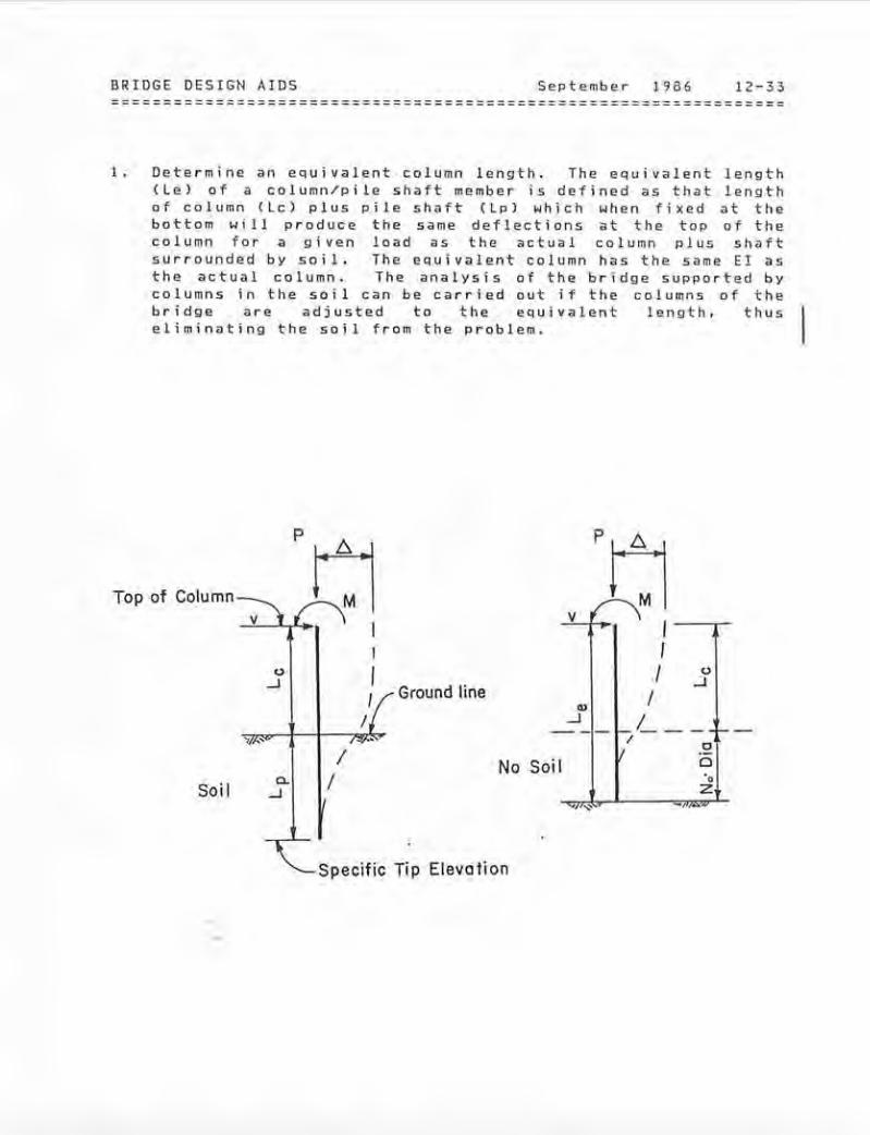
1. Dete rmi ne an equivalent column length . The equivalent length (Lel of a co lumn/pil e shaft member is defined as that length of column (Lcl plus pi le shaft (L p) which when fixed at the bottom wi 11 produce the same deflections at the top of the column for a g i ven load as the actua l column plus shaft surrounded b y soil . The equivalen t column has the same EI as the actual column. The a nal ys i s of the br i dge sup p orted by columns in the soi 1 can be ca rr ied out i f the columns of the b ridge are adjusted to t h e equ ival e nt le ng th , thus eliminating the soil from the problem.
p
Top of Column w 1~1 v v
I I
() ()
...J ./ JGround line
Q) I
-.J ·- - 1-.
/ L- - 1-
' ·' It .!:!I 0No Soil a. ••I zSoil ...J _," ··-
Specific Tip Elevation
-.

BRIDGE DESIGN AIDS September 1986 12-34
SIMPLIFIED METHOD
Often detailed soil informat ion lags the bridge preliminary report and it is desired to proceed with the design. Therefore, a 'Simplified Method' may be used to determine the equivalent length. The designer must obtain the soils general classification (sand or clay) and the standard penetration index CNl or an estimate of the soils relative density (loose, compact. dense etc . ) .
Assume the top of the column is at the e.G. of the superstructure, (3 feet above the soffit).
Lc = 20' + 3' = 23'
The charts are based on a single layer of soil. For this example, assume a si ngle layer of dense sand 55 feet thick and neglect the first 5 feet of loose sand.
Lc (Adjusted> = 23' + 5 ' = 28 '
Enter Figure 1. on page 16 with the blow count CN=45l and determine the number of pile diameters CNo=3> ' from the ground line to the point of effective fix i ty.
Le = Lc +(No x Dial = 28' + (3 x 5 .5'> = 44.5' (use 45'>
There are some s i tes where the 'Simplified Method' should not be used:
Cll Sites with large variations in soil stiffness with depth. (2) Sites with soft intermediate layers.
For these cases. use the "Rigorous Method' to determine the equivalent length as desc r ibed on page 12-45.

------ ------ -----
BRIDGE DESIGN AIDS September 1986 12-35 ==================~== ================= ================= ==== ======
2. Run programs BDS a nd BENT (with or without sides •H>y) at the service level using the equ iv alent column length (Le). Determine the necessary service co l umn loads to be used in programs YEILD and PILE at the TOP of the column. The shears at the top of t he column are obtained by summ ing moments about the bottom of the column and dividing by the equivalent length. Th e moments at the bottom of the column are used only to obtain the shea r fo r ces and in no case a r e to be used to design the shaft .
BENT OUTPUT - TOP of Column Loads : CServjce)
·---- LL + IMPACT ----· 1 2 3
DEAD TRANS LONG AXIAL LOAD MY-MAX MX-MAX N-MAX
MY 0 1367 65 117 MX -225 -80 -672 -108 N 1122 226 170 305 PMY 3944 2368 3944 PMX -175 -933 -175 PN 459 276 459
+P - · +P +M _..-1.......
+V ___: t' -M~ +V-
BDS Pi le Shoft
------ ------
------ ------
-----
-----
BRIDGE DESIGN AIDS September 1986 12-36 =================================================================
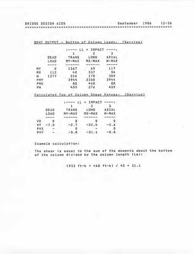
BENT OUTPUT Bottom of Column loads: (Service)
·---- LL + IMPACT ----· 1 2 3
DEAD TRANS LOHG AXIAL LOAD MY-MAX MX-MAX H-MAX
MY 0 136 7 65 117 MX 112 40 337 54 N 1277 226 170 305 PMY 3944 2358 3944 PMX 88 468 88 PH 459 276 459
Calculated Top of Column Shear Forcgs: CServjcg)
.---- LL + IMPACT ----. 1 2 3
DEAD TRANS LOHG AXIAl lOAD MY-MAX MX-MAX N-MAX
vx 0 0 0 0 VY -7.5 -2.7 -22.4 -3.6 PVX 0 0 PVY -5 . 8 -31.1 -5.8
Example calculation:
The shear is equal to the sum of the moments about the bottom of the column divided by th e co l umn length Clel:
(933 ft-k + 468 tt-k) / 45 = 31.1

------ ------ -----
BRIDGE DESIGN AIDS September 1986 12-37
3. Run STRUDL Co r SEISABl using the equ i valent column length and obtain the unreduced elastic ARS seismic loads at the top of the column. The loads are RMS values and thus do not have a sign .
STRUOL OUTPUT - TOP of Column Loads: <Unreduced ARSl
CASE I CASE II ------- ---------
MY 3667 11 0 0 MZ 5543 18475 N 41 138 vz 193 58 VY 252 84\
4. De t e r 11lne Wind, WL, LF, CF , and T load s at the top of the column using STRUDL or hand p r ocedu r es. Use the equivalent column length in the se anoolyses . The looods at the bottom ot the columns produced in the STRUDL analysis 11re fictitious ;;and in no case ;;a re t o be used to design the s haft.
ST RUDL OUTPUT - TOP ot Column Loa d s: CSeryicg)
Wind WL LF CF-MY TEMP
MY 175 14 0 0 0 MZ 289 107 86 0 420 N 2 1 1 0 1 vz 10 2 0 0 0 VY 13 s 4 0 22

BRIDGE DESIGN AIDS September 1986 12-38
5. Using the YIELD program, design the top of the column for group loads I thru VII (moments and axial loads). Use the equivalent length as the column length and appropriate fixities. This will allow the correct moment magnification facto rs to be calculated.
YIELD INPUT - Top of Column Service Logds (Groups I - VI J):
:---- LL + IMPACT ----: 1 2 3
DEAD TRANS LONG AXIAL LOAD MY-MAX MX-MAX N-MAX WINO WL LF CF TEMP
----- ----- -----I'IY 0 1367 65 117 175 14 0 0 0 HX 225 80 672 108 289 107 86 0 420 N 1122 226 170 305 2 1 1 0 1 PHY 3944 2368 3944 PHX 175 933 175 PN 459 276 459
CARS) UNREDUCED SEISMIC (Ductility Factor z • 6)
CASE 1 CASE 2
MY 3667 1100 HX 5543 18475 N 41 138
YIELQ RESULTS:
Column Diameter = 5.5 ft. Controlling Group Loading = IP Case 1 Percent Steel Required = 1.43 Total Area of Steel Required = 47.2 so . ln. Number of bars Required = 37.2 ~ 1.27 so. in.
* Use 38 - tl O bars
----- ------- ------- ---------
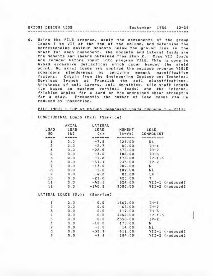
BRIDGE DESIGN AIDS September 19B6 12-39 ================================================================= 6. Using the PILE program, apply the components of the group
loads I to VII at the top of the column, and determine the corresponding maximum moments below the ground line in the shaft for each component. The moments and lateral loads are the moments and shears obtained from step 2. Case VII loads are reduced before input into program PILE. This is done to avoid excessive deflections wh i ch occur beyond the yield point. No ax i a 1 loads are app 1 i ed the because prog r am VIE LD considers slenderness by applying moment magnification factors. Obtain from the Eng ineering Geology and Technical Services Branch at Translab the soi 1 classifications, thickness of so i 1 layers, so i 1 densities , pile shaft 1ength (Lp based on maximum vertical loads> and the internal friction angles for a sand or the undrained shear strengths for a clay. FreQuently the number of load cases can be reduced by inspection.
PILE INPUT- TOP of Column Component Loads (Groups I- VII>:
LmiGITUDINAL LOADS (Mxl: (Service)
AXIA L LATERAL LOAD LOAD LOAD MOMENT LOAD
NO (k) ( k) (k-ft) COMPONENT
1 o.o -7 . 5 225.00 DL 2 0.() -2 . 7 80.00 IH-1 3 0.() -22.4 672.00 IH-2 4 o.o -3.6 108.0() IH-3 5 0.() -5.B 175.0() IP-1 , 3 6 o.o -31. 1 933.00 IP-2 7 0.0 -13.0 289.00 w 8 0.0 -5.0 107.00 WL 9 0.0 -4.0 86.0() LF
10 o.o -21.8 420.0() T 11 0.0 -42.1 924.0() VII-1 (reduced) 12 0 . 0 - 140.2 3080.0() VII-2 (reduced)
LATERAL LOADS (My): (Se rv ice>
l 0.() o.o 1367.00 IH-1 2 o.o 0.() 65 . 00 IH-2 3 0.0 0.0 117.00 IH-3 4 0.0 0.0 3944.00 I P-1, 3 5 0.0 o. o 2358.00 IP-2 6 o.o -10.0 1 75.0() w 7 ().0 -2.0 14.00 WL 8 o.o -32.1 612.00 VII-1 (reduced) 9 o.o -9.6 184.00 Vll-2 (reduced)

------ ---------
---------
BRIDGE DESIGN AIDS September 1986 12-40 =========================== ========== ============= ====== =========
PILE OUTPUT - Moments
LONGITUDINAL MOMENTS
MAX Mx LOAD MOMENT
NO (k-ftl
1 67 2 15 3 134 4 22 5 36 6 187 7 -161 8 -61 9 -48
1 0 -305 11 -490 12 -1717
; n Shaft below ground 1 i ne:
( Mx l : (Service)
LOAD COMPONENT
DL IH-1 IH-2 IH-3 IP-1,3 IP-2 w WL LF T VII-1 (reduced) VII-2 (reduced)
LATERAL MOMENTS (My l : <Service)
MAX My LOAD MOMENT
NO ( k-ft) -----
1 1370 2 65 3 117 4 3940 5 2370 6 -159 7 -34 8 -457 9 -137
LOAO COMPONENT
IH-1 IH-2 IH-3 IP-1,3 IP-2 ·w WL VII-1 VII-2
(reduced) (reduced)

------ ------ -----
BRIDGE DESIGN AIDS September 1986 12-41 =================================================================
7. Using the YIELD program. design the pile shaft below the ground l i ne for group loads I VII (moments and axial loads l. To obtain the unreduced seismic moments for Group VII loads, mu)tiply the reduced seismic moments in the pile shaft below the ground line, from step 6, by the ductility factor CZl. Use the equivalent column length and appropriate end fixities in the input.
YIELD INPUT - Service loads in Shaft CG~oups loads I - VII):
.---- ll + IMPACT ----. 1 2 3
DEAD TRANS LONG AXIAL LOAD MY-MAX MX-MAX N-MAX WIND WL LF CF TEMP
MY 0 1370 65 117 159 34 0 0 0 MX 67 15 134 22 161 61 48 0 305 N 1277 226 170 305 2 1 l 0 1 PMY 3940 2370 3940 ~MX 36 187 36 PN 459 275 459
UNREDUCED SEISMIC <Ductility Factor Z = 6)
CASE 1 CASE 2
MY 2742 822 MX 2940 10302 N 41 138
YIELD RESULTS:
Column Diameter = 5.5 ft. Controlling Group loading = IP Case l Percent Steel Required = 1.25 Total Area of Steel Required = 42.75 sq. in. Number of bars Required = 33 . 6 ~ 1.27 sq. in.
* Use 38 - 110 bars (same as at top of. column)
Top of column moments govern the design.

BRIDGE DESIGN AIDS September 1986 12-42 =================================================================
8. Run program YIELD in the check mode and determine the probable plastic moment and plastic shear at the top and bottom of the column. Assume the length of column is equal to the equivalent column length.
Note: The plastic moment capacity of the shaft may be different than the plastic moment capacity of the top of the column (ie. different diameter, percent steel, or axial load).
YIELP OUTPUT- Plastic Moment Capacjty of Column/Pile Shaft
Pp(top) 1122 K" Mp(topl 9699 K-Ft" Vp(topl = 436 K
Pp<bot> = 1277 K Mp<bot> 9921 K-Ft"

BRIDGE DESIGN AIDS September 1986 12-43 ============================================~================== = =
9. Using program PILE, apply at the top of the column the associated probable plastic moment <tip) and axial load (Ppl while incrementing the plastic shear until a second plastic hinge forms in the pile shaft .
a. If the plastic shear (Vpl is l ess than the unreduced elastic ARS (seismic) + dead load shear, design the shear reinforcement tor the plastic shear (Vpl.
c. If the plastic shear CVpl is greater than the unreduced elastic ARS (seismic> + de ad load shear, design the shear reinforcement for group loads I to VI and unreduced elastic group loads VII.
PILE INPUT/OUTPUT;
TOP TOP TOP AXIAL SHEAR MOMENT MAX. M LOCATION
LOAD p v M IN SHAFT FROM TO!' NO ( k)
----( k)
----Ck-ft l -----
(k-ttl -------
(ftl -------
l 1122 -450 9699 5600 37 2 1122 -500 9699 7310 37 3 1122 -550 9699 8950 37 4 1122 -560 9699 9280 37 5 1122 -570 9699 9610 37 .. 6 1122 -580 9699 9940 37 7 1122 -590 9699 10300 37 8 1122 -600 9699 10600 37
.. The plast ic hinge forms in the shaft.
Vp ( 580 Kl < Vars (849 Kl
Design the shear reinforcement for the plastic shear.
From YIELD in the CHEC K mode:
Use #5 bars at max. pitch = 3 5/8 in.
Shear Capacity of t5 bars = Vu ( 731 Kl > Vp ( 580 Kl OK
Note; The Pastic Hinge occured at 37 feet from the top of the col umn . The YIELD prog ram calculated the plastic moment capacity of the shaft at 45 feet from the top of the column . In this example the decrease in plast i c moment capacity due to a lower axial load at 37 teet as oppo,sed to 45 feet is small and is ignored.

BRIDGE DESIGN AIDS September 1986 12-44
10. The pile shaft is considered stable when a substantial decrease in pile shaft length does not result in excessive deflection. The amount of reserve shaft length is an indication of the factor of safety against overturning. A stab i 1 i ty ratio greater t han 1 . 0 is mandatory. A good rule of thumb is ; the greater the uncertaInty of the so i 1, then the greater the stability ratio. A stability ratio below 1.5 is not recommended without reliable soil data .
P = 1122 K V = -580 K Mp = 9699 K-Ft
Column Length <Lcl a 23'
PP I 'M
r-.P6 ~Def.-c <)
..J- 5 Ground line c 0
-<) -., ., 4
a.l /Q ., c 3. ::::i "}_' "0 c 2::J 0...
(!)
- Critical Pile Length ., Q
10 20 30 40 so eo 70 80
Lp - Pile shaft Length ( ft )
CRITICAL PILE LENGTH = 35 feet
STABILITY RATIO = 60/35 : 1.7
Pile Shaft Langth (Lpl vs. Oefl~ction <Defl Gl'aph 1.

------- ------- ----------- ---------
BRIDGE DESIGN AIDS September 1986 12-45 =================================================================
RIGOROUS METHOD
This procedure should be used at the following sites:
(1) Sites with lar ge variations in soil stiffness with depth. (2) Sites with soft intermediate layers.
1. Obtain Geology
detailed soil at Translab.
information from Engineering
SOIL DATA:
Sand Above The Water Table
Layer Class Unit Wt Thickness Friction Angle (?hi ) <Kef) <Ftl <Degrees)
----- -------- -------------------1 Loose .13 10 28
2 Dense .14 50 40
2. Apply apprcximate service level loads to the top of the column using the program PILE. Apply the shear and the moment as separate load cases to isolate them and their results. Note both the deflections and the rotations at the top of the column.
PILE INPUT/OUTPUT:
APPLIED APPLIED SHEAR MOMENT
LOAD M DEFLECTIONS ROTATIONS NO ( "k) (k-ft) < i n l <radl
1 100 1.5353 0.00439 2 500 0 . 2635 0 . 00102

-----------------------
-------------------------
BRIDGE DESIGN AJDS September 1986 12-46 : =================================================================
3. Solve for the equivalent length using the following equations. These four equations should result in approximately equal lengths. Average the results to determine the equivalent length.
l/3 l/2 3DvEI 2RvEI
L( Dv l = ------- L( Rv l = ------v v
l/2 2DmEI RmEI
U Dml = ------- L( Rml = ------M M
Dv = Top of column deflection due to applied shear ( v) •
Om = Top of column deflection due to applied moment ( M l • Rv = Top of column rotation due to applied shear ( v) •
Rm = Top of column rotation due to applied moment ( M l •
1/3 3M(l.5353/l2)*468b00M44 . 9
UDv l = ------------------------- = 43.2 ft 100
l/2 2M(0.00439)M468000M44.9
U Rv l = = 43.0 ft 100
l/2 2*(0.2635/l2)M468000M44.9
LCDml = = 43.0 ft 500
(0.00102)*468000*44 . 9 LC Rm l = 42.9 ft= --------------------
500
Le = C43.2 + 43.0 + 43.0 + 42.9l / 4 = 43.0 Ft
Note: 'Simplified' procedure gave an Le. = 45 . 0 Ft.

BRIDGE DESIGN AIDS September 1986 12-47 ==~==============================================================
Two observations should be noted with this example.
(1) Equivalent column lengths are used to design the superstructure and substructure. It Is conservatl ve to assume a longer equivalent column length for the design of the superstructure. Howev~r. this will produce unconservative top of column loads.
(2) A more accurate equivalent column length is produced with the additional effort displa.yed above, but for normal conditions the additional accuracy is not worth the required additional time and effort.
With the equivalent column modeling technique the bridge superstructure design, substructure design and the detailed geotechnical report may be completed simultaneously. Since the pile shaft design is dependent on the detailed soil information, the initial assumptions should be compared to the soil information included in the final geotechnical report.

BRIDGE ~ESIGN AIDS September 1986 12-48
7T-------~--------~--~------------------------------~ Depth to Point of Effective Fixity
in
SAND. 6 ~--------J---------~--F~~~P~\========R=/=C==P=i=le=s.==4=-=IO=f=t==Di=a=.======9
£1Column Length= 20 ·100ft, E • 468,000 ksf c (Using Reeses Approach, August, 1980)
·;c-"' N. x Dia.li: McBride/Maroney 2185.. 5
-~ ....., -w 0-...0 "' 4
z~.. E 0 0 0 -...
.&:1 "' 3
z" E
1--+--==1===Very SlightlyLoo$8 Loose Compact Compact Dense
2+-------~----~ '. ------~------+------~~~----~ 0 10 ~ w ~ 50 60
Standard Penetration Index- N, Blows/ft.
Approximateo-28 28-30 30-36 36·41 •in degrees
Depth to Point of effective Fixity in Sand
Figur-e 1.
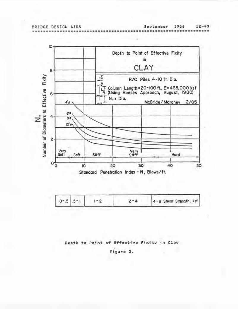
BRIDGE DESIGN AIDS September 1986 !2-49
10
Depth to Point of Effective F.ixity
in
CLAY8 >.
I~·;:c- RIC Piles 4·10 ft. Oio.-i:.: .. "' "='1!Column Length=20·IOO ft, E~468,000 ksf > (Using Reeses Approach, August, 1980)
-6
Iu.. N.x Cia. 4'~' Mc8ride I Moronev 2/85
w0 ~~,~. -"' 4z:;; a·-~-.. E ~·:~ ~ 0 0 ~~ - 20 ...., J:J · e ~ z
VerySoft
..
' Soft
'-Stiff
I
VerfStlf
I
I
1-Hard
I 10 20 30 40
Standard Penetration Index- N, Blows/ft.
o-.s l .s-1 1• 2 14 ·6 Shear Strenqth, ksf I
Depth to ?oint oi Effeetive Fixity in Cl~Y
Figure 2.