bridge deck construction manual - caltrans...the structure construction bridge deck construction...
TRANSCRIPT

State of California Department of Transportation Division of Engineering Services
Bridge Deck Construction Manual
Issued By Structure Construction
January 1991
Revision 01 October 2015

(This page left intentionally blank.)

DECK CONSTRUCTION MANUAL CHANGE LETTER REVISION NO. 1
Change Letter – Revision No. 1 October 30, 2015
The Bridge Deck Construction Manual is available on the Structure Construction (SC) Intranet site Technical Manuals: http://onramp.dot.ca.gov/hq/oscnet/sc_manuals
Revisions
SECTION REMOVE DATED SECTION INSERT DATED ENTIRE MANUAL
BRIDGE DECK CONSTRUCTION MANUAL
January 1991
ENTIRE MANUAL
BRIDGE DECK CONSTRUCTION MANUAL
Revision No. 1
October 2015
Background The State of California, Department of Transportation, Division of Engineering Services, Bridge Deck Construction Manual, January 1991, has been updated. The entire manual was revised, revisions include:
• Updated references to the current 2010 Standard Specifications (SS).
• Terms were updated to reflect the 2010 Standard Specifications. For example, approve is revised to authorize and cement revised to cementitious material.
• Updated the forms referenced in the manual to be consistent with the revisions made since the manual was issued.
• Added photos to depict operations described. Added descriptions and titles to tables and figures.
• Updated the format of the manual to meet the standards in the Style Guide for Structure Construction Technical Manuals.
• All appendices were removed. Relevant information and references were added to the text of the manual.
STEVE ALTMAN Deputy Division Chief Structure Construction Division of Engineering Services
CALTRANS ● DECK CONSTRUCTION MANUAL CHANGE LETTER

PREFACE OCTOBER 2015
Preface The Structure Construction Bridge Deck Construction Manual is intended to serve as a guide and a reference source for Bridge Engineers and others involved in field engineering and inspection of bridge decks under construction. As this manual is intended solely as guidance material, contract documents should always prevail in case of conflicts.
Most of the manual is devoted to construction techniques that will produce the structural quality and ride characteristics required by the 2010 Standard Specifications. References are made to the 2010 Standard Specifications and the Bridge Construction Records and Procedures Manual throughout the text to facilitate the reader’s use of this manual. There are also numerous tips and valuable information included within each chapter that are a compilation of the knowledge and wisdom gained from the experiences of Caltrans Bridge Engineers over the years.
The techniques and procedures involved in bridge deck construction have remained fairly consistent since the first publication of this manual in 1991. However, introduction of new materials, methods, and specifications such as the “Quiet Deck” and “Crack-Less Concrete Bridge Deck” specification have prompted a fresh look at how we prepare for the placement of deck concrete through the final application of the curing process. Early attention to details, along with sound engineering and construction practices, will help to ensure a bridge deck that will provide exceptional drivability and increased durability for the design life of the deck.
CALTRANS • DECK CONSTRUCTION MANUAL PREFACE

TABLE OF CONTENTS OCTOBER 2015
TABLE OF CONTENTS Chapter 1 Preconstruction Planning Page
1-1 Concrete Mix and Materials 1-2 1-1.1 Aggregates 1-2 1-1.2 Water-Cement Ratio 1-2 1-1.3 Admixtures 1-2 1-1.4 Mix Designs and Trial Batches 1-2
1-2 Batch Plants 1-3 1-3 Deck Construction Conference 1-4
1-3.1 Sequence and Limit of Placement 1-4 1-3.2 Location of Screed Rails and Construction 1-5
Joints 1-3.3 Concrete Conveyance, Placement Method, and 1-5
Rate 1-3.4 Finishing Method 1-6 1-3.5 Finishing Crew and Operators (for a typical 2-
land bridge) 1-6
1-3.6 Special Equipment Required of Advisable 1-7 1-3.7 Curing Equipment 1-7 1-3.8 Construction Details 1-8 1-3.9 Construction Conditions and Safety 1-8
Chapter 2 Bridge Deck Forms Page 2-1 Deck Construction 2-1
2-1.1 Types of Construction Details 2-1 2-1.2 Structural Adequacy 2-9 2-1.3 Vertical Alignment Grading 2-11 2-1.4 Horizontal Alignment 2-13
2-2 Inspection 2-13 2-2.1 Structural Adequacy, Mortar Tightness, and 2-13
Condition of Surface 2-2.2 Depths of Structural Sections 2-14 2-2.3 Hinges, Construction Joints, Paving Notches, 2-15
and Approach Slabs 2-2.4 Overhangs 2-16 2-2.5 Miscellaneous Items–Drains, Conduit, etc. 2-17 2-2.6 Expansion Joints 2-17
© Copyright 2015 California Department of Transportation All Rights Reserved
CALTRANS • DECK CONSTRUCTION MANUAL TC - 1

TABLE OF CONTENTS OCTOBER 2015
Chapter 3 Reinforcing Steel Page 3-1 General Specification Review for Bridge Deck
Reinforcement 3-1
3-1.1 Standard Details 3-1 3-1.2 Detailing and Fabrication 3-2
3-2 Inspection 3-2 3-2.1 Placement 3-2 3-2.2 Clearances 3-3 3-2.3 Splices 3-3 3-2.4 Blocking and Tying 3-4
Chapter 4 Grade Control, Screeds, and Bulkheads Page 4-1 Computations 4-1
4-1.1 “4-Scale” Contours 4-1 4-1.2 Profiles 4-2 4-1.3 Dead Load Deflection, Camber, and Settlement 4-4 4-1.4 Field Notes 4-6
4-2 Grading and Inspection 4-7 4-2.1 Contract Surveying 4-7 4-2.2 Levels and Transits 4-7 4-2.3 Overhangs 4-7 4-2.4 Screeds 4-9 4-2.5 Bulkheads 4-10 4-2.6 Paving Notches 4-11 4-2.7 Inspection Tools 4-11 4-2.8 Finishing Machines 4-11
Chapter 5 Concrete Placement and Consolidation Page 5-1 Transportation 5-1
5-1.1 Equipment 5-1 5-1.2 Delivery Rate 5-1 5-1.3 Mix Consistency and Uniformity 5-3 5-1.4 Inspection and Tests 5-3
5-2 Conveyance and Placement 5-4 5-2.1 Equipment 5-5 5-2.2 Inspections 5-7
5-3 Vibration 5-7
Chapter 6 Concrete Finishing and Curing Page 6-1 Specification Review for Concrete Deck Finishing 6-1
© Copyright 2015 California Department of Transportation All Rights Reserved
CALTRANS • DECK CONSTRUCTION MANUAL TC - 2

TABLE OF CONTENTS OCTOBER 2015
Chapter 6 Concrete Finishing and Curing Page 6-1.1 General Specifications 6-1 6-1.2 Highlights 6-1
6-1.2A Testing Roadway Surfaces 6-1 6-2 Curing Bridge Decks 6-8
6-2.1 Curing Compound Method 6-8 6-2.2 Curing Water Method 6-9
© Copyright 2015 California Department of Transportation All Rights Reserved
CALTRANS • DECK CONSTRUCTION MANUAL TC - 3

TABLE OF CONTENTS OCTOBER 2015
LIST OF TABLES Table Number Table 1-1 Finishing Crew and Operators 1-6
Table 5-1 All Concrete Tickets Should be Checked for Conformance 5-3
Table Description Page
© Copyright 2015 California Department of Transportation All Rights Reserved
CALTRANS • DECK CONSTRUCTION MANUAL TC - 4

TABLE OF CONTENTS OCTOBER 2015
LIST OF FIGURES Figure Number Figure Description Page Figure 2.1-1 Typical Deck Form Support for a Concrete Box
Girder Bridge 2-1
Figure 2.1-2 Typical Deck Sheathing Supports on a Concrete Box Girder Bridge
2-2
Figure 2.1-3 Stay-in-Place Metal Forming on a Precast Girder Bridge
2-3
Figure 2.1-4 Example of a Slab Bridge 2-4 Figure 2.1-5 Example of a Steel Girder Bridge 2-4 Figure 2.1-6 Example of a T-Beam Bridge 2-5 Figure 2.1-7 Sample T-Beam and Overhang Falsework Details 2-6 Figure 2.1-8 Sample Precast Concrete Girder Deck and Overhand
Falsework Details 2-7
Figure 2.1-9 Sample Steel Girder Bridge Falsework Details 2-8 Figure 2.1-10 Overhang Post Supports Bearing Directly on the
Falsework 2-10
Figure 2.1-11 A String-Line Strung Between Deck Dowels 2-12 Figure 2.2-1 Diagram of How to Use an Improvised Snap Tie
Depth Gauge 2-15
Figure 2.2-2 Finisher Checking the Freshly Placed Deck Concrete Near the Expansion Joint Blockout
2-16
Figure 2.2-3 Threaded Spacer Rods Used to Hold the Correct Width
2-17
Figure 2.2-4 Joint Seal Assembly Installation 2-18 Figure 3.2-1 Precast Mortar Blocks Under the Bottom Rebar Mat 3-4 Figure 3.2-2 Truss Bars Must Not be Allowed to Rotate out of
Vertical 3-5
Figure 4.1-1 Deck Contour Plot Sample 4-2 Figure 4.1-2 Calculate Grades for Widened Decks 4-2 Figure 4.1-3 Measuring for Precast, Prestressed “I” Girder Camber 4-4 Figure 4.2-1 Wedge System for the Overhang 4-8 Figure 4.2-2 Screed Rail Should Extend Beyond Pour Area 4-9 Figure 4.2-3 Check Carefully to Avoid Creating a Bump 4-10 Figure 4.2-4 Inspect Adjustment of the Finishing Machine 4-12 Figure 4.2-5 Check Finishing Machine Height 4-12 Figure 4.2-6 Fine Tune Legs 4-13 Figure 5.2-1 Crane and Bucket Concrete Placement 5-5
© Copyright 2015 California Department of Transportation All Rights Reserved
CALTRANS • DECK CONSTRUCTION MANUAL TC - 5

TABLE OF CONTENTS OCTOBER 2015
Figure Number Figure Description Page Figure 5.2-2 Concrete Pump 5-7 Figure 5.3-1 Vibrating Concrete 5-8 Figure 6.1-1 Smoothness Testing, per California Test 547 6-2 Figure 6.1-2 Coefficient of Friction Testing per California Test
342 6-3
Figure 6.1-3 Crack Comparator Makes Checking Crack Width Easier
6-4
Figure 6.1-4 Typical Grade Rail Setup 6-5 Figure 6.1-5 Typical Research Setup Quantifying Tire-Pavement
Interface Noise Level 6-6
Figure 6.1-6 Longitudinal Tining Typical Process 6-7 Figure 6.1-7 Close-up of Grooving 6-7 Figure 6.2-1 Applying Spray Cure from a Moveable Bridge
Following the Finishing Machine 6-9
Figure 6.2-2 Misting Cure Medium 6-9
© Copyright 2015 California Department of Transportation All Rights Reserved
CALTRANS • DECK CONSTRUCTION MANUAL TC - 6

CHAPTER 1 OCTOBER 2015
CHAPTER 1: PRECONSTRUCTION PLANNING
Preconstruction planning refers to the preliminary planning phases that precede actual construction and building. During preconstruction planning, project partners review the project parameters; assess resources, personnel, and construction methods; and ensure that all necessary details have been addressed.
Chapter 1 outlines key components, personnel, and procedures necessary for bridge deck construction. Following are a series of lists, guidelines, and questions to serve as frameworks for preconstruction planning:
• Section 1-1, Concrete Mix and Materials, draws from Chapters 2 and 3 of the Concrete Technology Manual to provide abbreviated lists of what to consider for deck concrete mix and materials—aggregates, cementitious materials, water cement ratio, admixtures, and strength requirements. Section 1 also addresses mix designs and trial batches as proposed by the Contractor and reviewed by the Structure Representative.
• Section 1-2, Batch Plants, covers the batch plant review, bringing together Contractor, district/region personnel, and structure personnel. Ideally, prior to batch plant review, bridge deck construction is discussed at the preconstruction conference, especially if there are unusual conditions.
Otherwise, the batch plant review should take place prior to and during trial batching the concrete for construction. Here, discuss the best management practices, grade control, access and operational considerations (traffic control, round trip times for concrete trucks, etc.), falsework requirements, sequence of concrete placement, scheduling, batch construction rate, backup plan, concrete quality control, and strength requirements.
• Section 1-3, Deck Construction Conference, emphasizes the importance of a deck construction conference for talking through project specifics. This section provides detailed lists for the Contractor and Engineer to discuss during the meeting: sequence and limit of placement; location of screeds and construction joints; concrete conveyance, placement method, and rate; finishing method; finishing crew and operators; special equipment required or advisable; curing equipment; construction details; and construction conditions and safety.
Preconstruction planning is akin to building a solid foundation: Taking the time at the start of a project to carefully plan and consider all facets of deck construction is vital to the success of a project.
CALTRANS • DECK CONSTRUCTION MANUAL CHAPTER 1 - 1

CHAPTER 1 OCTOBER 2015
1-1 Concrete Mix and Materials
The Concrete Technology Manual, Chapters 2 and 3, includes a complete discussion on concrete mixes and materials. The following is an abbreviated list of pertinent items to discuss prior to construction:
1-1.1 Aggregates1
Discuss the following items regarding aggregates: 1. Source. 2. Natural or manufactured. 3. Tests and gradation. 4. Moisture control. 5. Lightweight concrete.
1-1.2 Water Cement Ratio Detail these considerations regarding the water cement ratio:
1. Aggregate particle size and configuration. 2. Admixtures. 3. Strength requirements (typically found in the contract plans in the Structure
Design Notes).
1-1.3 Admixtures2
Specify type(s) of admixtures: 1. What type(s) are permitted?3
2. Are types compatible?4
3. How will admixtures affect strength, shrinkage, and workability? 4. What tests must be done? Obtain approval prior to incorporating in work. 5. Dispensing and calibration.
1-1.4 Mix Designs and Trial Batches5
1. The Contractor is responsible for mix designs, and the Structure Representative reviews them. As this is a review and not an approval, the Structure Representative must make a timely review to bring any issues to the Contractor’s attention as soon as possible. Discuss the following:
2. Cementitious material content and strength requirements.6
1 2010 Standard Specifications (SS), 90-1.02C, Aggregates, 2010 SS 90-1.02F (2), Storage of Aggregates, 2010 SS 90-2, Minor Concrete, 2010 SS 90-3, Rapid Strength Concrete. 2 2010 SS 90-1.02E, Admixtures, or Specials. 3 Bridge Construction Records and Procedures Manual (BCR&P) 100-4.0. 4 2010 SS 90-1.02E(1), Admixtures, General. 5 2010 SS 90-1.01C(6), Mix Design; Concrete Technology Manual, Chapter 3, Review of Concrete Mix Designs.
CALTRANS • DECK CONSTRUCTION MANUAL CHAPTER 1 - 2

CHAPTER 1 OCTOBER 2015
3. Admixture(s).7
4. Combined gradation of aggregates.8
5. Type of cement.9
6. Workability, placing, and finishing characteristics. 7. Schedule of trial batches.10
8. Uniformity (using the same concrete mixes as other projects supplied by the same plant).
9. Shrinkage.11
1-2 Batch Plants
Conduct a field review of the Contractor's proposed batch plant at an early stage in the contract for specification compliance. District/region personnel usually make this review, but it is good practice for Structure personnel to accompany them during the review.
It is a good idea for Structure personnel to be aware of what the review involves and to check the following items:
1. Aggregate storage and handling (intermingling, contamination, moisture control, etc.).12
2. Storage of cementitious materials (protection, weighing, venting, sampling, quantity available, etc.).13
3. Admixture(s) (storage, introduction, and measurement). Mineral admixtures are treated as Supplemental Cementitious Materials (SCM) in the 2010 Standard Specifications.14
4. Water (adjustment for aggregate moisture content variation).15
5. Plant equipment and measuring devices (compliance with specifications, condition, and maintenance).16
6 2010 SS 51-1.02B, Concrete; 2010 SS 90-1.01D(5)(a), Compressive Strength General; 2010 SS 90-1.02B(1), Cementitious Materials General; and Specials.
7 2010 SS 90-1.02E, Admixtures. 8 2010 SS 90-1.02C(4)(d) Combined Aggregate Grading. 9 2010 SS 90-1.02B(2), Cement. 10 2010 SS 90-1.01D(5)(b), Compressive Strength, Prequalification. 11 2010 SS 90-1.01D(3) Shrinkage; and Specials. 12 2010 SS 90-1.02F(2), Storage of Aggregates; Concrete Technology Manual Chapter 4, Proportioning, Mixing, and Transporting. 13 2010 SS 90-1.02B(1), Cementitious Materials, General. 14 2010 SS 90-1.02E(1), Admixtures, General; 2010 SS 90-1.02F(4)(b), Proportioning and Dispensing Liquid Admixtures. 15 2010 SS 90-1.02D, Water; Concrete Technology Manual Chapter 4, Proportioning, Mixing, and Transporting. 16 2010 SS 5-1.33, Equipment; 2010 SS 9-1.02B, Weighing Equipment and Procedures; 2010 90-1.02F, Proportioning Concrete.
CALTRANS • DECK CONSTRUCTION MANUAL CHAPTER 1 - 3

CHAPTER 1 OCTOBER 2015
6. Transit-mix trucks (compliance with specifications, capacity, condition, and maintenance)17 and volumetric mixer trucks.18
7. Hot and/or cold weather provisions.19
8. Inspection facilities provided. 9. Delivery ticket format and information.20
1-3 Deck Construction Conference
Prior to the stem and soffit pour, hold a meeting with the Contractor to discuss the particular features of the deck being constructed.
It is important that the Engineer understands the Contractor's proposed methods so that they can determine if these methods are compatible with the specifications and requirements of the contract. Resolve any previously unidentified differences at this time.
Below is a general outline of what this meeting might entail, but the Engineer is responsible for the particulars of each job and should determine and discuss the following:
1-3.1 Sequence and Limit of Placement Address the following questions as they pertain to the project:
1. Do the plans and specifications require certain concrete placement sequences? 2. How will the Contractor handle screed rail grades for varying width of deck,
multiple pours, screed rail supports buried on girder stems, etc.? 3. Will the Contractor place any longitudinal or transverse joints other than those
shown on the plans?21
4. Are longitudinal joints located on or close to a lane line? 5. Is stage construction required or proposed by the Contractor? 6. Are there any long-standing hinges? 7. What quantity of concrete is required for the various deck segments? 8. Will placement interfere with public traffic, existing power lines, or other
obstructions? 9. In what direction is the pour? 10. Are there any closure pours? 11. How are closure pours formed, and how are they stripped?
17 2010 SS 90-1.01C(7), Concrete Delivery; 2010 SS 90-1.02G(3), Transporting Mixed Concrete; 2010 SS 90-1.02G(4), Time or Quantity of Mixing. 18 2010 SS 90-3, Rapid Strength Concrete. 19 2010 SS 90-1.03C, Protecting Concrete; Concrete Technology Manual Chapter 4, Proportioning, Mixing, and Transporting; 20 2010 SS 90-1-01C(7), Concrete Delivery. 21 See SP BO-5.
CALTRANS • DECK CONSTRUCTION MANUAL CHAPTER 1 - 4

CHAPTER 1 OCTOBER 2015
12. Does the contract provide for falsework release alternatives? 1-3.2 Location of Screed Rails and Construction Joints The location of screed rails and construction joints is critical. Discuss the following details:
1. Locations the Contractor plans on placing the rail supports for the finishing machine: a . Edge of deck. b . At longitudinal construction joints. c . At exterior or intermediate girder location.
2. Type of structure may influence screed rail position and support. 3. Details for longitudinal joints referred to in the Standard Plans (SP). Locating
screed rail supports at the girder is preferred.22
4. Evaluation of the support system of screed rails for deflection, rotation, and stability.
5. Screed rails should be adjustable within themselves. 6. Grade control at longitudinal and transverse construction joints. 7. Grade control for screed rails and method of establishing grade. 8. Stability of bulkheads for construction joints.
1-3.3 Concrete Conveyance, Placement Method, and Rate Discuss the following with regards to the length and time of haul from batch plant to construction site:
1. Can the concrete be delivered at a uniform rate? 2. Will delivery, placement, and finishing of concrete cause a hazard to the public? 3. After delivery to the site, what placing method will be used to place the concrete
in the deck (pump, tailgate method, bucket and crane, slick line, etc.)? 4. Will the placing method require additional support considerations in the
formwork of reinforcing steel? 5. What is the anticipated rate of placement? Is this consistent with the rate of
delivery, and how will this affect the surface finishing capabilities? 6. Will there be proper vibration of concrete after placement? What is the number of
vibrator crew members required for accomplishing proper vibration? 7. What penetration depth is required? How will this affect method of placement
(pumping) or the capability of the strike-off machine to properly work a given penetration in the concrete?23
8. Will conveyance and placement be interrupted for any reason such as moving the pump truck or crane and/or finishing equipment? What provisions are in place for keeping concrete fresh?
9. Will the placement method cause segregation or result in a non-uniform or uneven pour front?
10. Where are the Contractor’s approved temporary concrete washouts?
22 SP B0-5. 23 2010 SS 90-1.02A, Materials, General.
CALTRANS • DECK CONSTRUCTION MANUAL CHAPTER 1 - 5

CHAPTER 1 OCTOBER 2015
1-3.4 Finishing Method Consider the following regarding the finishing method for concrete:
1. Finishing is the Contractor's responsibility.24
2. The Engineer's interest is in the end results of: a. Rideability. b. Durability. c. Surface texture (for coefficient of friction and sound) surface crack intensity. d. Physical properties of the concrete (plastic and final states) and cure details. e. Longitudinal tining or grooving if applicable.
3. The Engineer's responsibility is to establish grade control points. 4 . Special finishing considerations:
a . Lightweight concrete. b . Adverse weather conditions (heat, wind, cold, rain, etc.). c . Overlays. d . A review of the project Rain Event Action Plan (REAP) as it applies to a deck
pour.25
1-3.5 Finishing Crew and Operators (for a typical 2-lane bridge) Because the specifications do not require specific methods in deck finishing, the Contractor decides on the size and classification of the crew. However, the staffing of a deck pour is an important area of discussion with the Contractor since the staffing affects the time required to complete the deck pour. This affects concrete delivery, which may be delayed by traffic, problems at the batch plant, etc. The site of pour must not be too far in distance from batch plant in order to ensure a timely pour. The degree of mechanization and the individual abilities of laborers will vary from job to job, but a suggested average crew size is detailed in Table 1.1:
Table 1.1. Finishing Crew and Operators
Number of Positions Duties 1 Foreman who is in charge of the pour 2 Laborers to rake ahead of the machine 1 Operator of the machine 2 Finishers for edging 1 Broom and cure laborer 2 Crew members operating vibrators 1 Bridge Carpenter or Pile Driver Carpenter to watch the falsework on slab
bridge pours and overhang supports for large and heavy overhangs 1 Laborer tending concrete truck
24 2010 SS 51-1.01D(4), Testing Roadway Surfaces. 25 2010 SS 13-3.03B, Rain Event Action Plan.
CALTRANS • DECK CONSTRUCTION MANUAL CHAPTER 1 - 6

CHAPTER 1 OCTOBER 2015
1-3.6 Special Equipment Required or Advisable Discuss the following precautions as they pertain to the project:
1. Cooling of concrete in hot weather requires:26
a. Ice machine at the plant or refrigerated water. b. Fogging or sprinklers over the coarse aggregate stockpiles. c. Shade cover over the aggregate stockpiles. d. Cool water supply at deck pour. e. Fogging rebar and forms with cool water ahead of placement (be cautious of
over-watering to avoid runoff, which may pond at falsework supports or cause erosion and storm water discharges).
2. Critical back-up equipment for machinery (pumps, light plants, generators, spare parts etc.).
3. Heating and protecting concrete in cold weather requires: a . Heating for water. b . Heating for coarse aggregate. c . Covering stockpiles with black polyethylene sheeting (visqueen). d . Protecting completed deck as necessary to maintain temperature requirements.
(Possible use of an external heat source. In freezing weather, deck curing temperatures have been kept in the mid 60°F by using burlene or carpets on the deck, followed by black polyethylene sheeting (visqueen), followed by additional carpets.)
4. Possibility of rain. If there is impending inclement weather, do not schedule concrete deck placements. However, if there is a chance of rain, take precautionary measures and make appropriate materials available at the site at all times, such as:
1. Black polyethylene sheeting (visqueen). 2. Method of placing and removing black polyethylene sheeting (visqueen). 3. A plan for getting rid of excess water on the low side of deck. 4. Building an emergency bulkhead.
1-3.7 Curing Equipment Discuss the following considerations regarding curing:
1. Water supply at the site. 2. Sufficient supply and pressure to produce a fog mist. 3. Fog nozzle. 4. Adequate means of applying curing compound.27
a . Contractor should demonstrate (prior to concrete placement) the adequacy of the system for applying curing compound to the deck surface (e.g. power atomizing spray).
b . The conventional hand pump garden sprayer is not permitted for deck curing
26 2006 SS 90-6.02, Machine Mixing. 27 2010 SS 90-1.03B(3)(c & d), Mixing and Application (Curing Compound Method).
CALTRANS • DECK CONSTRUCTION MANUAL CHAPTER 1 - 7

CHAPTER 1 OCTOBER 2015
compound. This includes Hudson type spray cans. 5. Ensure that there are no leaks in the curing compound hose lines. The hoses or
other components must not drag and damage the fresh texture on the deck surface. 6. Water for cure and for use in deck construction is to conform to the requirements
of the Standard Specifications.28
7. Adequate supply of burlene or other cure blankets for the deck square footage. 8. Means of keeping the different types of curing compound separate and
identifiable. 9. Method to prevent cure blankets from blowing off or moving in the event of
strong wind. This would be in addition to the weight of any cure water (for example, 2 x 6s laid on the cure blankets at edges and elsewhere as necessary).
10. Will cure water run continuously or will the blankets or carpets be watered on a regular schedule?
1-3.8 Construction Details Make a complete review of plans and specifications, including:
1 . Skew versus camber versus strike-off device and screed rail grade. 2 . Is the bridge on a radius, or are the edges of decks flared? 3 . Super-elevation and transitions. 4 . Bent cap steel related to deck steel (cap steel is tight up into cap stirrups and deck
steel is on top of the bent cap steel). 5 . Openings through bent caps, deck, and bent cap steel clearance. 6 . Hinges and prestressing hardware versus deck grades. 7 . Steel girder structures versus deck grades. 8 . P/S P/C girders: deck grades and thickness for uneven cambers and cross slopes. 9 . Variable span lengths: non parallel abutments or bents. 10. Stem and diaphragm stirrup hook location and resulting effect on deck steel
placement. 11. Specified openings and the effect on screed rail control for deck grades. 12. Longitudinal and transverse construction joints. 13. Details of paving notch. 14. Sidewalk and railing steel layout and height. 15. Lane lines. 16. Utilities, drains, manholes, etc. 17. Block-outs in the deck for prestress duct vents.
1-3.9 Construction Conditions and Safety Discuss the following construction conditions and safety precautions:
1. Will appropriate installation of rails and kickboards at the edge of the deck, finishing and cure bridges, and other locations be performed?29
2. Is the Contractor ensuring the placement of equipment so that they will not
28 2010 SS 90-102D, Water. 29 Construction Safety Orders-CSO 1620 & 1621.
CALTRANS • DECK CONSTRUCTION MANUAL CHAPTER 1 - 8

CHAPTER 1 OCTOBER 2015
operate over the public or railway? Lane closures must be utilized to prevent pumps, cranes, or other equipment from being placed over the traveling public.
3. Will equipment interfere with overhead power or utility lines? 4. Will the public be adversely affected by delivery of concrete? Is there a
possibility that placement will be interrupted? 5. Will strike-off location and finishing machine length interfere with hand railing?
Handrails should be kept in place. 6. Runways for foot traffic should not be less than 20" wide. 30
7. Are eye-wash stations placed and spaced properly per Cal/OSHA GISO 5162?
30 CSO 1624.
CALTRANS • DECK CONSTRUCTION MANUAL CHAPTER 1 - 9

CHAPTER 2 OCTOBER 2015
CHAPTER 2: BRIDGE DECK FORMS
Constructing a bridge deck that is both structurally sound and durable requires careful planning and preparation. This chapter discusses specific details about essential elements of bridge deck construction and inspection.
2-1 Deck Construction
In the construction process, pay careful attention to construction details, structural adequacy, alignment and grading. The following essential elements are discussed in greater detail in this chapter:
1. Types of construction details. 2. Structural adequacy. 3. Vertical alignment and grading. 4. Horizontal alignment.
2-1.1 Types of Construction Details1
Deck construction centers around two types of finished forms: 1. Stay-in-place or lost-deck forming. 2. Exposed surface forms.
2-1.1.A Stay-In-Place or Lost-Deck Forming By far the most common stay in place form system used for box girder bridge construction is known as a lost-deck form system. Although there are variations in forming methods and construction details, the general system of forming a typical box girder bridge deck is shown on Figures 2.1-1 and 2.1-2.
Figure 2.1-1. Typical Deck Form Support for a Concrete Box Girder Bridge.
1 2010 Standard Specification (SS), 51-1.03C(2), Forms. CALTRANS • DECK CONSTRUCTION MANUAL CHAPTER 2 - 1

CHAPTER 2 OCTOBER 2015
Figure 2.1-2. Typical Deck Sheathing Supports on a Concrete Box Girder Bridge.
For typical cast in place structures the lost-deck forms/falsework that support the bridge deck concrete are typically comprised of sheathing, joists, ledgers, and possibly posts.
Sheathing can be either: • Plywood, interior or exterior grade. • Oriented strand board. • Other adequate board.
Sheathing should be mortar tight with all holes patched. In lieu of dutchmen patching, metal is sometimes used to cover small holes and gaps in forms to prevent mortar leaks. Metal and precast concrete stay-in-place forms, some having a structural significance in the final product, have been permitted on some projects (usually detailed on the contract plans or by Contract Change Orders [CCO]).
The sheathing sits atop the joists which are generally 4 x 4 or 2 x 4 material.
Ledgers support the joists and are typically supported by either: • Posts. • Rebar placed in the side of the girder stem prior to pouring, bars are generally #4,
#5 or #6. • Low velocity powder driven nails typically used to attach wood ledgers to
concrete.
For precast or steel girder bridges it is common to see stay-in-place forms in locations where:
• The removal of the forming would be difficult. • Would require additional time possibly adding a season to the work. • Cause environmental impacts.
When stay-in-place forms are proposed via a CCO, it is important to gather input from
CALTRANS • DECK CONSTRUCTION MANUAL CHAPTER 2 - 2

CHAPTER 2 OCTOBER 2015
Structure Maintenance and Investigation (SM&I), as well as Structure Design (SD), as the girders may need to be checked for the additional dead load. See Figure 2.1-3 for an example of stay-in-place forms.
Figure 2.1-3. Stay-in-Place Metal Forming on a Precast Girder Bridge.
2-1.1.B Exposed Surface Forms In deck construction, exposed surfaces refer to those surfaces that, when the forms are removed, the concrete surface will be visible. These surfaces include the edge of the deck, soffits of slab bridges, deck soffits for T-beam, steel girder, precast concrete girder bridges, and deck overhangs for all bridge types. In slab bridges, the plywood soffit forms are directly attached to and supported by the falsework joists or stringers and are considered an integral part of the falsework system (see Falsework Manual). Deck slab forms for T-beam, steel girder, and precast concrete girder bridges, and overhangs are usually of conventional joist and plywood construction. The bridge superstructure dictates the method of support for the forms. See Figures 2.1-4, 2.1-5, and 2.1-6 for examples of a slab bridge, a steel girder bridge, and a T-beam bridge. Figures 2.1-7 through 2.1-9 are construction details for each type of bridge superstructure. The bridge superstructure dictates the method of support for the form system.
CALTRANS • DECK CONSTRUCTION MANUAL CHAPTER 2 - 3

CHAPTER 2 OCTOBER 2015
Figure 2.1-4. Example of a Slab Bridge.
Figure 2.1-5. Example of a Steel-Girder Bridge.
CALTRANS • DECK CONSTRUCTION MANUAL CHAPTER 2 - 4

CHAPTER 2 OCTOBER 2015
Figure 2.1-6. Example of a T-Beam Bridge.
CALTRANS • DECK CONSTRUCTION MANUAL CHAPTER 2 - 5

CHAPTER 2 OCTOBER 2015
Figure 2.1-7. Sample T-beam and Overhang Falsework Details.
CALTRANS • DECK CONSTRUCTION MANUAL CHAPTER 2 - 6

CHAPTER 2 OCTOBER 2015
Figure 2.1-8. Sample Precast Concrete Girder Deck and Overhang Falsework Details.
CALTRANS • DECK CONSTRUCTION MANUAL CHAPTER 2 - 7

CHAPTER 2 OCTOBER 2015
Not
es
1)
Not
per
mitt
ed u
nles
s sho
wn
on sh
opD
raw
ings
and
app
rove
d by
the
Eng
inee
r.Se
ct. 5
5-1.
02B
(7) S
tand
ard
Spec
ifica
tions
.
2)
Loa
ds m
ust b
e ap
plie
d w
ithin
6″
of a
flan
geor
stiff
ener
and
dis
trib
uted
to p
reve
nt lo
cal
dist
ortio
n of
the
web
. Tem
pora
ry st
ruts
mus
tbe
pro
vide
d as
nec
essa
ry to
res
ist l
ater
allo
ads.
Sect
. 55-
1.03
B S
tand
ard
Spec
ifica
tions
.
Figure 2.1-9. Sample Steel Girder Bridge Falsework Details.
CALTRANS • DECK CONSTRUCTION MANUAL CHAPTER 2 - 8

CHAPTER 2 OCTOBER 2015
2-1.2 Structural Adequacy Check the adequacy of all bridge deck forming systems by stress analysis, as they are considered part of the supporting falsework.2 It should be noted, however, that form behavior cannot always be predicted or determined by analytical calculations of its load carrying capacity. If the physical properties and condition of the material are known, calculate theoretical deflections. In the case of lost-deck forms, the sheathing is frequently a material (plywood chip board), or grade of material, whose modulus of elasticity is questionable, particularly when the moisture content approaches the saturation point. Consequently, deflections may, and probably do, exceed some arbitrary value commonly accepted and known in industry as a negligible amount.
There is also evidence that deflections and joint take-up of the forms is not instantaneous, but continues, in some cases, beyond the initial set period of the concrete, resulting in noticeable surface cracking along the stems.
Deflection and settlement can and do occur after concrete placement. Normally, yielding of the forms is not structurally detrimental to the deck slab as long as the deflection does not continue after the initial set period. A uniform riding deck surface may not be achievable if the concrete subsides after form deflection and settlement.
The joists supporting the deck slabs of steel, precast concrete girder bridges, and deck overhangs are considered falsework. The sheathing deflections or undulations between joists, constituting forms for exposed concrete surfaces, are covered by the Standard Specifications.
The structural adequacy and deflection of timber joists is determined by stress analysis. If the manufacturer's loading data is in question, load test patented joists to determine the dead load deflection for the actual condition of loading.
Normally, ledgers support patented or timber joists for steel and precast concrete girder bridges. Ledgers are either underpinned by posts to the bottom flanges of the girders or suspended from the girders by hangers.
Use custom or homemade hangers (e.g. bar stock bent to form a "U" which fits over the top of the girders) only after they are satisfactorily load tested and approved by the Engineer. This method of fabrication creates high stress points at the bends, and use of this type of hanger has resulted in total failure under relatively light loads. For this reason, Structure Construction (SC) policy is to use half of the ultimate load carrying capacity of these hangers as the allowable load.3 Many types of patented hangers are available for deck forming systems on either steel or precast concrete girder bridges. The safe working loads recommended by most manufacturers are based on, and subject to,
2 2010 SS, 48-2.01D(3)(a), Quality Control and Assurance, Design Criteria, General. 3 Allowable or Working Load = Ultimate Load ÷ 2. CALTRANS • DECK CONSTRUCTION MANUAL CHAPTER 2 - 9

CHAPTER 2 OCTOBER 2015
specific loading conditions, and any modification of the units themselves or deviation from their intended use will affect their load carrying capacity. The hanger bolts must be either flush with or a specified distance from the edges of the girder flange. The rated capacity of some hangers depends on whether they are used on steel or concrete girders. Investigate hangers for potential uplift and subsequent rotation issues due to unbalanced loading.
The forming system may provide restraint, or the hangers may be welded to the girders subject to the conditional requirements.4 Do not weld or tack brackets, clips, shipping devices, or other material not described to any part of the girders unless shown on the shop drawings. On conventional steel girder bridges, the extension of the haunch or deck forms under the girder flanges affords restraint.
Figure 2.1-10. Overhang Post Supports Bearing Directly on the Falsework.
The falsework system supports overhang forms by underpinning soffit forms with posts (See Figure 2.1-10).
On steel and precast concrete girder bridges, overhang brackets or jacks attached to the exterior girder support the forms (as shown in Figures 2.1-8 and 2.1-9). Both systems are considered falsework and are analyzed as such.5
Construct falsework and concrete forms on steel structures such that loads applied to girder webs:
1. Are applied within 6″ of a flange or stiffener. 2. Do not produce local distortion of the web.
4 2010 SS, 55-102B(7)(a), Welding, General. 5 2010 SS, 55-1.03B, Falsework. CALTRANS • DECK CONSTRUCTION MANUAL CHAPTER 2 - 10

CHAPTER 2 OCTOBER 2015
Provide temporary struts and ties to: 1. Resist lateral loads applied to girder flanges. 2. Prevent appreciable vertical movement between the edge of deck form and the
adjacent steel girder.
When screed rails are located in the overhang area, deflection must be minimal for appearance and satisfactory grade control. Determination of deflection is difficult particularly when brackets or jacks with cantilevered joists or outriggers are used. If analysis or precedent cannot ascertain form behavior and deflection, a load test is justified.
Contractors widely use patented overhang brackets and jacks, such as those manufactured by:
1. Dayton Superior Concrete Accessories, Inc. 2. Waco Scaffold and Supply Company. 3. OCM, Inc.
Design information, including deflection data, for these units is available from the manufacturer and must be requested from the Contractor to check these products for contract compliance.
2-1.3 Vertical Alignment and Grading Preconstruction planning is critical to vertical alignment and grading. The Contractor must determine and propose a deck framing system, the types of material to be used, where screed rails will be located (e.g. on the edge of deck forms), and how the forms will be adjusted. Discuss grading requirements and procedures at this time.
Control for lost-deck forms in box girder bridges is usually established on lost-deck dowels after the soffit and stem pour. Remove the girder forms and walkways used during the stem and soffit pour. They are usually used as lost-deck forms. When the walkways are removed, safe access to lost-deck dowels is also removed. The contractor must install adequate safety features to safely access the lost-deck dowels before establishing decks grades in the field.
The Engineer gives cuts to the top of deck. Provide a cut from the top of a rebar dowel cast in the girders at predetermined points to give adequate control for deck forming. The Contractor then determines the elevation of form supports. In some cases you may use a hacksaw to make a saw cut on the rebar dowel (or lost-deck dowel) at the top of the deck elevation at each dowel. Run a string line transversely across the deck to the lost deck dowel at the corresponding station (See Figure 2.1-11). The Contractor will move the string line along the length of the bridge from dowel sets to dowel sets and build lost-deck forms from this string line. Provide grades at all breaks in the grade and at intervals not closer than 8 ft longitudinally and 24 ft transversely to the centerline of bridge. A typical distance between lost-deck dowels is in 10-foot stations. If deck grading will be CALTRANS • DECK CONSTRUCTION MANUAL CHAPTER 2 - 11

CHAPTER 2 OCTOBER 2015
complicated, additional dowels may be necessary. Discuss dowel layout with the Contractor in advance. Consider the amount of vertical curve and camber when determining these intervals so that string lining between these points will not cut out camber or vertical curve. Refer to the Falsework Manual for more discussion on camber.
Figure 2.1-11. A String-Line Strung Between Deck Dowels.
Right after establishing deck grades, make a visual check at random locations to see how these grades correlate with what is already poured. To quickly visually assess deck grades, place tape at the saw cut on the lost-deck dowel. The tape must be consistently placed below the saw cut. This tape will provide a quick visual check, as well as a quick reference to locate saw cuts for later use:
1. Do the stirrup heights fit? (Check the length of the stirrup before the stem pour.) 2. Is the structural depth correct? Now is the time to consider any necessary grade
adjustments, not after placement, when the deck steel is found to be not quite right.
Grade for the deck overhangs requires extra attention since these grades produce one of the more obvious lines of the structure. First, determine all grades at the locations where a grade adjustment is to be made. Field-measure the locations of the overhang supports and plot these on the 4-scale drawing or edge of deck profile line. Before grading the overhangs, enough load should be on the forms to tighten up the joints. Usually this is accomplished when a major portion of the deck rebar is in place.
Many different schemes have been proposed for grading overhangs (e.g. grade every other support, grade it all 0.25″ low the first time then bring it up, etc...). Whatever method is used, always grade upward to the final elevation. Until the Contractor's system has been proven on the job, the Engineer should be prepared to check each location. The final check of the overhang is the "eye ball," but make sure to complete all final wedging and adjustments at the face of girders and the overhang. See Chapter 4, Grade Control, Screeds and Bulkheads, for a detailed discussion on grading overhangs.
CALTRANS • DECK CONSTRUCTION MANUAL CHAPTER 2 - 12
CHAPTER 2 OCTOBER 2015
2-1.4 Horizontal Alignment The particular horizontal alignment of the specific structure under construction dictates the tools necessary to provide this line. Before the horizontal line is set on the edge of deck forms, the grade of these forms must be close. The Contractor can accomplish this rough grading with the use of templates and the lost-deck grade dowels.
Establish straight lines with a transit and/or string line. Establish curved lines with a transit and standard chord offset procedure using the centerline of abutments and bents as control points. On complex projects, get District Surveys Services involved.
No matter what method of establishing line is used, always check the following two items:
1. Check into known points at each end of the structure. 2. Check the overall width at several locations throughout the length of the structure.
2-2 Inspection6
The inspection process affects the entire area encompassing the deck. From construction to overhangs and expansion joints, inspection assesses how the deck is built, any and all materials and artifices touching and associated with the deck, and the deck’s impact on the overall surroundings.
The following are essential elements to consider for the inspection phase: 1. Structural adequacy, mortar tightness, and condition of surface. 2. Hinges, construction joints, paving notches, and approach slabs. 3. Overhangs. 4. Miscellaneous items–drains, conduit, etc. 5. Expansion joints.
2-2.1 Structural Adequacy, Mortar Tightness, and Condition of Surface The structural adequacy of the forming system, as with falsework, is not determined solely on the basis of stress analysis. Inspection of the forms is necessary to ensure their stability. Personnel who are thoroughly familiar with the forming plans (i.e., the person who checked the falsework or someone who at least reviewed it) should perform the inspection.
Where appearance is important, mortar tightness and surface condition for the forms of exposed concrete surfaces is also important. Because the lost-deck is not visible, the subject of mortar tightness is often dismissed. Nevertheless, the Contractor must be directed to patch any lost-deck form hole greater than 0.25 in. and any spaces between
6 See the Field Construction Practices Manual for additional guidance. CALTRANS • DECK CONSTRUCTION MANUAL CHAPTER 2 - 13

CHAPTER 2 OCTOBER 2015
fillet and deck soffit. Loss of mortar or grout through holes or cracks in the forms affects the appearance of the concrete, as well as its structural quality. Tin is often used to patch holes or cracks, and spray foam is also useful in that capacity, especially around deck drains, etc., so long as there is solid backing. Note that construction paper and aluminum are not to be used to patch lost-deck forms.
2-2.2 Depths of Structural Sections Check deck slab thickness, including the effective depth(s) and coverage of reinforcing steel, to ensure structural adequacy and conformance. This is usually done by measuring from a string line pulled between the screed rails or bulkheads prior to the finishing machine adjustment. Additionally, take a measurement from the strike-off or rollers of the finishing machine during the adjustment of the machine. During the pour, check the depths again by stabbing the plastic concrete following strike-off. See Figure 2.2-1 for a visual of a good tool for checking depth—a snap tie with the correct deck thicknesses marked.
CALTRANS • DECK CONSTRUCTION MANUAL CHAPTER 2 - 14

CHAPTER 2 OCTOBER 2015
Figure 2.2-1. Diagram of How to Use an Improvised Snap Tie Depth Gauge.
Effective depth and clearance of reinforcement is discussed in Chapter 3, Reinforcing Steel.
2-2.3 Hinges, Construction Joints, Paving Notches, and Approach Slabs When using a finishing machine, set forms or bulkheads for hinges and expansion and construction joints approximately 0.25 in low to clear the rollers and to make the grade at the joint. After final floating, attach a filler strip or edger board to the form for dressing and edging the joint, or saw cut the edge later. After the finishing machine passes, check the section of deck leading up to the joint at several locations with a straightedge held longitudinally to the bridge (See Figure 2.2-2). This allows the concrete finishers to blend in the joint and match the deck.
CALTRANS • DECK CONSTRUCTION MANUAL CHAPTER 2 - 15

CHAPTER 2 OCTOBER 2015
Figure 2.2-2. Finisher Checking the Freshly Placed Deck Concrete Near the Expansion Joint Blockout.
On multi-frame bridges connected by a hinge, it is important to adjust grades so that the final surfaces match on either side of the hinge. See Memo to Designers 11-34, Hinge Curl for details. After the first deck is poured, profile and monitor it. Using the information from the first deck, adjust the grades of the second deck to match the first. Don't forget to include settlement in the second deck grades when trying to match the first.
After the deck concrete is placed, construct the top section of the abutment backwall, formed between the expansion joint and paving notch. Use the deck surface to establish the finished plane for this section.
Check proposed approach slab grades (as well as the entire bridge) with the road plans when reviewing the 4-scale drawings. After the bridge deck is poured, it should be profiled so that adjustments can be made in the approach slab grades if necessary. Typically, profiling the last 100 ft of the bridge deck is sufficient to make any adjustments between the as-built deck profile, the new approach slab, and the new roadway profile. Consult with District personnel so that both parties are aware of any proposed grade changes.
2-2.4 Overhangs The importance of stability of the deck overhang forming systems for aesthetic reasons and deck grade control was noted earlier. To avoid repetition, their inspection is included in the following:
1. Chapter 4, Grade Control, Screeds and Bulkheads. 2. Inspection Check List for bridge forming and support systems in Field
Construction Practices Manual.
CALTRANS • DECK CONSTRUCTION MANUAL CHAPTER 2 - 16

CHAPTER 2 OCTOBER 2015
2-2.5 Miscellaneous Items–Drains, Conduit, etc. All drains, conduit, manholes, etc. should be shown and identified on the 4-scale layout and grade sheet for each structure. Attach road plans and standard plans showing pertinent drainage, electrical details, and sign details to the bridge plans for reference.
Miscellaneous items must be checked for proper location and be adequately secured to prevent movement during concrete placement and finishing operations. Set drains low enough to be in accordance with the plans. Set the plane of the grate parallel to the deck surface with the inlet properly sealed to prevent entrance of concrete and other foreign material.
2-2.6 Expansion Joints7
Saw cut joints to be sealed with type A and B seals at locations shown on the contract plans and to the dimensions determined in accordance with Bridge Construction Records and Procedures Manual, BCM 135-2.0, Bridge Deck Expansion Joints and Joint Seals.
Figure 2.2-3. Threaded Spacer Rods Used to Hold the Correct Width.
7 2006 SS, 51-2.02. Sealed Joints. CALTRANS • DECK CONSTRUCTION MANUAL CHAPTER 2 - 17

CHAPTER 2 OCTOBER 2015
Figure 2.2-4. Joint Seal Assembly Installation.
Place joint seal assemblies in block-outs between the deck and approach slab or in hinge sections. Concrete is then deposited around the assembly. Typically threaded spacer rods hold the correct width of the seal assembly opening as concrete is placed around the joint seal assembly (as shown in figure 2.2-3). The Contractor should submit shop drawings for joint seal assemblies early for acceptance so that the reinforcing steel can be checked for proper clearance at these locations. Figure 2.2-4 shows an example of a joint seal assembly being installed.
Set these assemblies to exact bridge deck grade and carefully check grade for their entire length. The assembly is sometimes warped or bent during fabrication by welding or galvanizing, in which case they should be straightened by reworking. Give careful inspection consideration to skewed joints so the assembly fits properly at the barrier rail. See Bridge Construction Records and Procedures Manual, BCM 135-2.0, Bridge Deck Expansion Joints and Joint Seals, for more discussion on joint seal assemblies.
Prior to joint seal installation, conduct grinding to avoid any damage to the joint seal or assembly. The Standard Specifications do not require deck grinding to be completed prior to the installation of type A or B joint seals, as it does for joint seal assemblies. Unless deck grinding is performed first, the correct depth of installation remains uncertain. To achieve a smooth deck before installing the joint seal assembly, place asphalt or concrete (rat slab) over a sand bed in the joint seal assembly block-outs prior to deck grinding. The Contractor is responsible for any damage to the joint seal assembly and is responsible for constructing the completed roadway surface true to the required grade and cross section, including smoothness across the joint seal or assembly8.
8 2010 SS, 51-1.03F(5), Finishing Roadway Surfaces. CALTRANS • DECK CONSTRUCTION MANUAL CHAPTER 2 - 18

CHAPTER 3 OCTOBER 2015
Chapter 3: Reinforcing Steel
Reinforcing steel (rebar, reinforcing bar, or reinforcing) as used in reinforced concrete structures, is strength-graded steel that has been manufactured with deformations to provide tension capacity of the concrete element.
• Section 3-1 below details industry standards and resources for rebar use and fabrication.
• Section 3-2 describes mandatory inspection standards, including proper placement, clearances, and rebar modification such as splicing, blocking, and tying.
3-1 General Specification Review for Bridge Deck Reinforcement
All reinforcement for bridges must conform to specifications of the American Society for Testing and Materials (ASTM) A 706/A 706M.1 ASTM A 615/A 615M Grade 40 or 60 are still allowed for use in some applications. Welded wire fabric may be used in certain circumstances, but must be on an equivalent area basis. If plans show that the deck reinforcing has an epoxy coating-1.0, then all Standard Specifications (SS) 52-2, Epoxy-Coated Reinforcement and Epoxy-Coated Prefabricated Reinforcement, requirements must be met.
3-1.1 Standard Details Standard Details are found in the Standard Plans. The Index to Plans sheet of the structure contract plans usually lists the standard plans used. Following are examples of commonly used standard details. Standard Plan Detail BO-5, lists transverse and longitudinal reinforcing spacing requirements, location of deck construction joints, and deck reinforcing placement notes. If there are access openings in the deck, check B7-11 for reinforcing details. Review the plans to ensure that access openings are not in wheel lines. If there is a conflict, discuss it with the Structure Designer. For placement of deck drains, check plans B7-5 through 8. Concrete Barrier details are found in Plans B11-54 through B11-70.
Other information, such as hook and bend length, and radius, are in the Bridge Construction Records and Procedures Manual (BCR&P), Volume 2, Section 165, Reinforcing Steel. The details conform to American Concrete Institute (ACI) code requirements for hooks and bends. ACI code (BCM 165-1.0) governs unless different lengths are shown on the plans.
1 2010 SS 52-1.02B, Bar Reinforcement.
CALTRANS • DECK CONSTRUCTION MANUAL CHAPTER 3 - 1
CHAPTER 3 OCTOBER 2015
3-1.2 Detailing and Fabrication Deck contours (4-scales) should be made available to the Reinforcing Steel Fabricator to reduce the probability of detailing errors. Special details for deck reinforcing and change orders affecting reinforcement should be brought to the Contractor’s attention.
Errors in detailing or fabrication are more likely to occur on bridges with the following characteristics:
• Varying girder spacing. • Varying deck thickness. • Large skew. • Varying skew. • Wide, curved bridges with small curvature radius. • Future widening.
Fabrication is seldom a problem unless the standard industry practices for fabrication dimensions, as shown in BCR&P, BCM 165, Reinforcing Steel, are ignored.
3-2 Inspection
On bridges with the characteristics listed in 3-1.2, watch for incorrect reinforcing in the corners, truss bars not centered over the girders, incorrect bar termination location, omission of bars at the overhangs and at the bent cap, etc. Also common is omission of reinforcement shown on the Standard Details, especially around barrier rail-mounted utilities. The best time to inspect truss bars for length and depth is prior to placement.
During field inspection of the reinforcing steel, check the markings on the bars. The markings signify the bar size, grade, and steel mill. A complete guide to reading the bar markings is BCM 165-2.0, Identification of Reinforcing Steel Bars, of the Bridge Construction Records and Procedures Manual.
Carefully confirming that all deck reinforcing and clearances meet contract plans and Standard Specification requirements improves safety and reduces future repair costs. Following are some specific materials and procedures to include during inspections.
3-2.1 Placement Reinforcing must be placed as shown in the contract plans, the Standard Plans, or any applicable change orders. A significant amount of current bridge maintenance funds are spent on deck rehabilitation projects. It is important for deck reinforcement and clearances to match plans to reduce future deck rehabilitation costs.
Correct placement is covered in the Standard Specifications2. For specific practices and
2 2010 SS 52-1.03(D), Placing.
CALTRANS • DECK CONSTRUCTION MANUAL CHAPTER 3 - 2

CHAPTER 3 OCTOBER 2015
standards not covered in the Standard Specifications, check with the Designer to determine the tolerances or variations in placement that are allowed.
Periodic and timely inspections are strongly recommended during bar placement for early detection and correction of errors. Proactive inspection prior to placement can save the project time and money. Timely inspection minimizes re-work costs and results in a better product.
3-2.2 Clearances Correctly placed deck reinforcement that provides the planned clearance or cover for the bars is extremely important. Too little cover will not adequately protect reinforcing from water and chloride intrusion resulting in rusting that can dramatically shorten the life of the deck. This is especially true in a marine environment or where de-icing chemicals are used. Concrete spalling on the deck or edge of the deck can occur from corroding reinforcing bars with inadequate cover; this creates unsightly stains and costly maintenance.
Always inspect the clearance to the top deck, the minimum clearance at the boundaries, and the reinforcing bar ends to make sure they match the typical section in the contract plans. In marine environments or in areas where de-icing chemicals are used, cover may be increased. In addition, on segmental bridges or bridge decks constructed under the quiet deck specification, there most likely will be thicker deck coverage. This thicker cover allows for texture grinding later on to provide a final grooved, quiet riding surface.
3-2.3 Splices Lap splicing is the most common method of splicing deck bars.3 The minimum lap splice length for ASTM A 706/A 706M rebar is 45 bar diameters for rebar sizes #8 or smaller and 60 bar diameters for #9 thru #11 rebar. Unless otherwise shown on the plans, the splices in adjacent bars must be staggered. The minimum distance between the staggered splices must be the same as the length required for a lap splice in the largest bar. During inspection, make sure the splices are securely tied and will not move during the deck pour. Additional longitudinal mild steel reinforcement that is continuous over the bent caps must be continuous or spliced using ultimate butt splices.
For widenings and closure pours, reinforcing splices may be welded or mechanically spliced.4 A list of approved couplers for service splice qualifications or ultimate butt splice qualifications may be found in the Authorized List of Couplers for Reinforcing Steel.5
3 2010 SS 52-6.03B, Lap Splicing. 4 2010 SS 52-6.03C, Service Splices and Ultimate Butt Splices and BCM 165-7.0, Qualification of Bar Reinforcement Splices, for the correct procedures to follow for welded or mechanically spliced reinforcing. 5 http://www.dot.ca.gov/hq/esc/approved_products_list/pdf/steel_reinforcing_couplers.pdf
CALTRANS • DECK CONSTRUCTION MANUAL CHAPTER 3 - 3

CHAPTER 3 OCTOBER 2015
3-2.4 Blocking and Tying All deck reinforcing must be securely tied and blocked up off the deck to prevent any movement during placement of the deck concrete. The use of wooden, plastic, or aluminum supports is not permitted.6 If ferrous metal chairs are used, they must have at least one inch of cover. The plastic coatings on the chair feet are not considered to be effective cover. The Specifications also do not permit placing reinforcing bar into wet concrete during the pour. Precast mortar blocks (dobies) are used to assure attainment of the required concrete cover on the bottom rebar and for ferrous chairs (Figure 3.2-1).
Figure 3.2-1. Precast Mortar Blocks Under the Bottom Rebar Mat.
Between the girders, “ducked" or buried bars are shown on the plans to support the bottom mat. Typically, they are #4 bars spaced at about two feet on center. Truss bars and precast mortar blocks support the top mat. Truss bars must be securely tied to prevent any rotation. Truss bars, as shown in Figure 3.2-2, must not be allowed to rotate out of vertical position. If they rotate, the top mat will be out of position and result in reduced deck strength. If truss bars are not used, the contractor will use precast mortar spacer blocks to support the top mat. At or near the girders, some contractors will attempt to support the top deck mat on the stirrup tails. This can be an effective method of support, provided that the tails are correctly positioned to do this task and the bars are securely tied to the tails to prevent movement before or during the pour.
6 2010 SS 52-1.03D, Placing.
CALTRANS • DECK CONSTRUCTION MANUAL CHAPTER 3 - 4

CHAPTER 3 OCTOBER 2015
Figure 3.2-2. Truss Bars Must Not be Allowed to Rotate out of Vertical.
Mats of reinforcing steel must be tied firmly and securely in position during the pour. This is accomplished by wiring at intersections and splices. ACI recommends that bars be tied at every other intersection and this may be adequate in most cases. More frequent tying may be necessary at corners, over bent caps, and other special locations.7
72010 SS Section 52-1.03D, Placing.
CALTRANS • DECK CONSTRUCTION MANUAL CHAPTER 3 - 5

CHAPTER 4 OCTOBER 2015
CHAPTER 4: GRADE CONTROL, SCREEDS, AND BULKHEADS
Chapter 4 covers computations, grading, and inspections performed by the Contractor, Engineer, Structure Representative, field personnel, and construction personnel. Specific construction components include profiles, overhangs, screeds, bulkheads, and paving notches. These require in-depth scrutiny and review to prevent problems in grading and construction. Tools— particularly the finishing machine—benefit from regular maintenance and care for adequate measurement and construction. This chapter addresses the importance of attention to detail, proper planning, well-maintained tools, and meticulous processes for grading and inspection.
4-1 Computations
By thoroughly following best practices and procedures, the Contractor, Engineer, field personnel, and other partners safeguard the quality of their work and can seamlessly integrate new construction within existing frameworks. Topics covered in this section include:
1. “4-Scale” contours: Plot the entire deck construction environment and present an overview of elements, grades, and more.
2. Profiles—bridge deck widening and new construction: Ensure that new construction is well graded and built at the outset.
3. Dead load deflection, camber, and settlement: Plan for ongoing maintenance and review as construction settles and shifts.
4. Field notes: Detailed note taking and documentation are integral to the quality assurance process.
4-1.1 “4-Scale” Contours Bridge deck contour plots drawn to a scale of 1-in. to 4-ft are referred to as “4-scales” (see Figure 4.1-1). In most cases, bridge deck contour plots (4-scales) are available from Structure Design. Bridge Construction Memo (BCM) 2-4.0, Bridge Deck Contours and Geometrics,1
outlines how to obtain 4-scale contour plots.
1 http://onramp.dot.ca.gov/hq/oscnet/sc_manuals/crp/vol_1/crp002.htm
CALTRANS • DECK CONSTRUCTION MANUAL CHAPTER 4 - 1

CHAPTER 4 OCTOBER 2015
Figure 4.1-1. Deck Contour Plot Sample
After receiving the 4-scale contours, perform a detailed check of the plan dimensions and grades. Correct detail errors and conflicting dimensions before making copies of the bridge deck contour plots (4-scales) available to the Contractor. Check each bridge 4-scale sheet against the final finish grade profiles and the superelevation diagrams shown in the roadway plan sheets. Draw the edge of deck profiles to check for dips or humps caused by superelevation transitions, alignment tapers, and other anomalies. Extend the profile beyond the bridge paving notches and include retaining walls, wingwalls, bridge approach rail, and a section of roadway. Sections of the 4-scale may require revision to avoid possible grade problems.
4-1.2 Profiles When widening or installing a new deck, the Engineer and field personnel must work together to ensure the new deck is carefully constructed and graded. Problems and poor alignment can be prevented, particularly at the outset of the project, with careful attention to detail, an understanding of potential hurdles and problems, and foresight. It is more efficient and effective to do the job well and thoroughly the first time than to attempt reworking a hurried pour.
4-1.2.1 Widenings Widened decks are typically constructed to match both an existing bridge deck and theoretical grades generated for the outside edge of the widened deck. Field personnel generally develop deck contours for widening (see Figure 4.1-2).
Figure 4.1-2. Calculate Grades for Widened Decks.
CALTRANS • DECK CONSTRUCTION MANUAL CHAPTER 4 - 2
CHAPTER 4 OCTOBER 2015
Some features of existing decks that may cause problems are: 1. Too much camber. 2. Too little camber. 3. Bumps not corrected on the original contract. 4. Rough surfaces and other defects under removed overlays, curbs, and rails.
Correct these problems with grinding or overlays.
Sometimes medians are widened so that the top deck must match two existing bridge decks and a theoretical centerline profile. This type of widening may result in the existing bridge deck profiles conflicting with each other and with the theoretical centerline profile. If this occurs, adjust the profiles, vary the deck slopes, or seek other solutions. Closure pours between new left and right structures pose similar challenges. Determine the existing bridge deck profile elevations and cross slope by potholing overlays on existing bridges needing widening.
When edge profiles for the existing decks and roadways are included in contract plans, verify their elevations prior to starting construction. Develop profiles as early as possible to determine if remedial work is necessary. Identify grade problems and solutions early as well. For structures that cross over ramps, roads, or tracks, ensure that required permanent clearances will not be impaired by using field-acquired grades and extending the planned widening girder bottoms or soffit elevations from the existing structure.
4-1.2.2 New Construction On long ramp structures, viaducts, and structures requiring multiple pours, potential bump problems exist at each transverse bulkhead, expansion joint, or hinge. Proper profiling and grade control of the adjacent work safeguards against grade or slope discontinuities at the edge of deck grades.
Extra care and caution are required when a second deck pour must match an existing deck at a hinge or a transverse construction joint. Care taken at the end of the first pour is essential to obtain a satisfactory joint. It is much easier and more effective to match a correctly poured joint than it is to compensate for irregularities.
After the first deck pour, create a cross section and profile of the deck. Establish a grid of points on the first day after the pour, preferably at even stations and offsets. Shoot and monitor elevations at this time until grades are established for the second deck pour. Use these elevation points to check for the possibility of long-term falsework settlement and to monitor the movement of post-tensioned hinges. Adjust soffit grades, “lost deck,” and screed grades if necessary. Extend and compare profiles of the first deck onto the second deck profiles with theoretical values. Then, adjust the second deck pour grades.
Maintain exact stationing and bench data on decks with steep cross-slopes, sharp vertical curves, or steep profile grades. The Engineer assures the correct stationing for the next segment, either
CALTRANS • DECK CONSTRUCTION MANUAL CHAPTER 4 - 3

CHAPTER 4 OCTOBER 2015
by marking stationing in the newly finished edge of deck or another method. Lay out and shoot edge of deck points the first day after the pour as well.
4-1.3 Dead Load Deflection, Camber, and Settlement Camber for the decks of conventionally reinforced concrete box girder, T-beam, and slab bridges is the algebraic summation of the anticipated long-term deflection due to creep of the concrete and the initial dead-load deflection. Experience shows that for box girder and T-beam structures, essentially all of the falsework deflection occurs when the girders are poured. This is true even for post-tensioned bridges with long falsework spans. Studies indicate that for a post-tensioned box girder bridge, 50% or less of the theoretical deflection due to the deck slab dead load is realized when the deck is poured. Therefore, the deck camber for conventional reinforced or post-tensioned box girder and T-beam structures would normally not include falsework deflection.
Deck camber for precast, prestressed girder bridges depends on the elapsed time between stressing the girders and placing the deck (see Figure 4.1-3). Because a significant portion of the dead load is not applied to the girders until the deck is placed, the prestressed "I" girders tend to creep upwards. The Contractor furnishes camber calculations2 for precast, prestressed girders and shows them on the shop drawing submittal. When reviewing the shop drawings, pay particular attention to the time between casting and storage of the girders and the placement of the deck, especially for stage construction projects and widenings.
Figure 4.1-3. Measuring for Precast, Prestressed “I” Girder Camber.
Deck camber for steel girder bridges includes the initial deflection of the girder(s) from the dead load of the deck but does not include the deflection caused by the weight of the girder(s). In the case of composite design, add a residual amount to compensate for the additional deflection due to drying shrinkage of the slab.
2 http://www.dot.ca.gov/hq/esc/techpubs/manual/bridgemanuals/bridge-memo-to-designer/page/Section%2011/11-1.pdf.
CALTRANS • DECK CONSTRUCTION MANUAL CHAPTER 4 - 4

CHAPTER 4 OCTOBER 2015
Long-term deflection of conventionally reinforced concrete bridges continues over a period of about four years. Approximately 25% of the total deflection occurs immediately after falsework is removed. Delay falsework removal to reduce initial and total deflections.
Consequently, on widenings3, the plans or Special Provisions frequently require falsework support for a longer period of time. To further reduce the grade differential between widened and existing decks, the specifications may also require that a minimum period of time elapse between falsework release and closure pour. Typically, contract plans show only one camber diagram for the widening and is usually restricted from deflecting the same as an independent bridge. Depending on the amount of camber and the time of the closure pour, the total anticipated deflection for the section of the widening located next to the existing bridge may never be realized. Therefore, it may be necessary to adjust the amount of camber for this section of the widening in order to reduce possible grade differentials that could develop between the widened and existing decks.
As with falsework members, the dead load deflection of steel girder bridges must be checked. Before steel girder fabrication, check the effect of built-in camber using the 4-scale layouts. Use fills from the girder flanges to grade deck forms and screeds for steel girder bridges. Determine deck forms by comparing the profiles of the girders with those of the finished deck, including anticipated deflection, along the girder line.
There are three important factors to remember in connection with steel girder profiles: 1. Safety: Do not perform work of any kind without adequate safety devices, such as a
safety belt attached to a cable, a safety rail running the length of the girder, safety nets, etc.4
2. Grade points: Accurately lay out grade points and reference them to the center lines of bearing.
3. Elevation check timing: Only run level circuits early in the morning when temperature variation is minimal and while the girder temperature is constant or stable. Do not go back later in the day and attempt to check elevations. These elevations may not even be the same the next morning.
Settlement can occur in the falsework and the forming system. Bridge deck settlement normally results from form take-up, assuming that falsework settlement is terminated or stabilized. Exceptions include:
1. Slab bridges where settlement is compensated for by screed adjustment during concrete placement operations.
2. Post-tensioned bridges where falsework settlement occurs because of prestressing forces applied after deck pour.
3. Deck-forming systems like overhangs, designated as falsework.
3 http://www.dot.ca.gov/hq/esc/techpubs/manual/bridgemanuals/bridge-memo-to-designer/page/Section%209/9-3.pdf. 4 Caltrans Safety Manual, Chapter 12, Personal Protective Equipment.
CALTRANS • DECK CONSTRUCTION MANUAL CHAPTER 4 - 5

CHAPTER 4 OCTOBER 2015
Both the ASTM Standard Specifications and the Falsework Manual address the falsework settlement. Some falsework settlement is normal because of take-up in forms, but the quality of workmanship must yield falsework that will “support the loads imposed without excessive settlement or take-up beyond that shown on the falsework drawings."
4-1.4 Field Notes An organized and systematic approach towards bridge deck construction is important. Proper field book entries are essential for providing required bridge deck elevations in a timely manner. Entries for box girder deck construction should include the following:
1. Lost deck elevations: Saw cuts are typically placed on girder stirrups (or rebar) cast into the girder stems to provide the Contractor with top deck elevation control points. The Standard Specifications state, “Elevation control points will not be closer together than approximately 8 ft longitudinally and 24 ft transversely to the bridge centerline.” Space the deck elevation control points closely enough to allow use of a string line to check the deck. Deck elevation control points can be grade marks placed a constant distance below finished deck grade, grade marks at finished grade, or fills to finished deck grade from preset points.
A small error of closure normally exists between field-measured points and layout-scaled dimensions. This is true in soffit grades as well as lost deck grades. If these errors are not adjusted and discrepancies are allowed to accumulate, the camber diagrams will not correctly relate to the substructure, and wingwall and column grades will not match the superstructure grades.
One acceptable method for adjusting errors is to assume that bents, piers, and abutments are in the correct location and prorate the error out within the spans. Layout the points on the 4-scale as measured in the field and shrink or expand the scale to make field measurements match the layout. Adjust soffit stations and soffit grade points accordingly.
2. Overhangs: When the overhang is formed after the girder stem pour, the Contractor should use the lost deck grades to establish grade for the inside portion of the overhang located next to the exterior girder.
Once the locations of the overhang adjustment points are determined, generate the overhang grades. Typically, these grades are taken directly from the edge of deck profiles drawn to check the 4-scale contours. Depending on the forming system used, additional camber may need to be added to the overhang grades. Always check the bench mark used for grading the overhang against that used for shooting lost deck grades.
3. Screeds: Use overhang grades to shoot the screed. Depending on the forming system used, additional camber may need to be added to the screed grades to compensate for deflection due to the weight of the finishing machine.
CALTRANS • DECK CONSTRUCTION MANUAL CHAPTER 4 - 6

CHAPTER 4 OCTOBER 2015
4. Bulkheads: Finishing equipment establishes finish deck grades at bulkheads and paving notches.
Tie together all grades used for deck construction and always check back to previously shot grades for continuity. Spot check lost deck grades when shooting overhang grades to check for long-term falsework settlement. Coordinate stationing and level data between adjacent pours to provide a matching deck surface. Location and accessibility to bench marks require foresight to prevent the loss of key elevation points.
4-2 Grading and Inspection
Grading and inspection address the many different components that must come together for quality assurance. As in the previous section, care and consideration of each of these elements is imperative to establish consistent grade and pass inspection. This section gives guidance regarding the following elements during grading and inspection:
1. Contract surveying: Structure Representatives and bridge construction personnel must check the quality of surveying conducted by Contractors throughout the project.
2. Levels, transits, and inspection tools: Regularly scheduled tool maintenance is critical. 3. Overhangs, screeds, bulkheads, and paving notches: The grading, inspection, and correct
placement of these structural elements are some of the most important processes for deck construction.
4. Finishing machines: Since there is usually only one available per job, successful bridge construction requires careful preparation and regular maintenance of this machinery.
4-2.1 Contract Surveying Some projects, such as segmental bridge construction, incorporate contract surveying to reduce staffing and to make the Contractor responsible for providing the line and grade required to complete the job. Bridge construction personnel are expected to perform enough surveying to assure that each structure is built to the lines and grades specified. Typically, the Structure Representative checks almost all of the Contractor's survey points at the beginning of each job. As the project progresses, the Structure Representative may adjust the amount of checking to reflect the level of confidence developed in the Contractor's surveyors.
4-2.2 Levels and Transits Establish a systematic schedule for maintaining, cleaning, and pegging levels on every project. Post it and keep it updated. Handle instruments with care, as they often get out of adjustment. Check level legs for stability as they can get loose and wobbly at leg tips and connection to the plate. Check Lenker rods for loose sole plates and sloppy operation.
4-2.3 Overhangs Grading and inspecting the overhang bulkheads and the overhang supports are two of the most important items of deck construction. Check the Contractor's plans for structural adequacy and details that may result in uneven settlement. Give extra attention to connections and bearing areas. All joints must be solid in order to prevent differential deflections due to the weight of the
CALTRANS • DECK CONSTRUCTION MANUAL CHAPTER 4 - 7

CHAPTER 4 OCTOBER 2015
finishing machine. Look for potential stability problems such as a tipping overhang caused by loads being concentrated along the outside section of the overhang.
If the overhang is constructed at the same time as the girder stem forms, the overhang must be kept clean. Methods to protect overhang forms include plastic sheeting, “lost deck” plywood covering, and building paper. If the overhang is built after the girder stem pour, check the grade at the exterior girder before the deck reinforcing steel is placed. Always check the overhang lumber for defects as the overhang is being constructed.
Install overhang jacks per the manufacturer's recommendations. For example, do not extend jacks too far, and make sure vertical legs and screw adjustments are plumb. Use bracing to prevent girder rotation and to keep web connections on steel girder bridges from dimpling. Check lumber for defects and watch for tipped joists. Ensure that the tails of the jacks do not encroach on the minimum vertical clearance.
Always rough grade the overhang before establishing the edge of deck line. Otherwise, the edge of deck line may shift if the overhang grades are adjusted an appreciable amount.
Discuss with the Contractor in advance and plan the methods and manpower requirements for grading the overhang. To get the required smooth lines that are the telltale hallmark of pride in workmanship, review with the Contractor will be necessary throughout the project. Emphasize form continuity and the importance of rechecking previously graded joints with rodmen and carpenters. Sometimes previously graded points change in elevation as the overhang is graded.
Figure 4.2-1. Wedge System for the Overhang.
It is common practice for the Contractor to rough-grade the overhang approximately 0.50 in. low. The Engineer then directs the final grade adjustments. It is usually easier and quicker to jack or wedge the overhang up than to try to lower it (see Figure 4.2-1). Grade both the interior and exterior supports simultaneously before the final grading operation to prevent overhang support geometry from causing a grade change at the edge of deck. After grading, feather wedge the joists tightly and eyeball the overhang.
CALTRANS • DECK CONSTRUCTION MANUAL CHAPTER 4 - 8

CHAPTER 4 OCTOBER 2015
4-2.4 Screeds Since screeds are normally placed on the overhang, one method for grading is to shoot the screed using the overhang grades and adjust the Lenker rod to compensate for the elevation difference between the overhang and the screed. Alternatively, the Contractor uses a template, or “story pole,” set on the graded overhang to grade the screed. As a last resort, the Contractor can grade both the overhang and the screed from the deck grades on the exterior girder. Spot-check screeds for adequate support.
Screeds for the finishing machine should be two in. diameter heavy wall pipe with spacing of supports not exceeding the recommendation of the manufacturer, typically 24 to 30 in.
Make sure the screed pipe is in good condition. Screeds should run the full length of the pour and extend beyond both ends enough for the finishing equipment to clear the pour area (see Figure 4.2-2). Grade screeds beyond the limits of the pour for proper grade at the bulkheads and paving notches. Put screed pipe splice sleeves in place to prevent cantilever action of the screed pipe. Vibrations sometimes turn screed pipe saddle adjustments and overhang adjustment nuts; wire or secure them to prevent rotation. Check all screed support elements during concrete placement. Non-uniform screed displacement or settlement can be caused by:
1. Lack of washers between adjusting nut and edge of deck panel. 2. Spaces between top plate and studs of overhang panel. 3. Spaces between overhang soffit and edge of deck panel.
Make field notes and have a level available during every deck pour in case of grade problems.
Figure 4.2-2. Screed Rail Should Extend Beyond Pour Area.
CALTRANS • DECK CONSTRUCTION MANUAL CHAPTER 4 - 9

CHAPTER 4 OCTOBER 2015
4-2.5 Bulkheads The Standard Specifications5 require the Contractor to “locate longitudinal construction joints in bridge decks along lane lines if a joint location is not shown.” Past practice is to place longitudinal bulkheads within a foot of lane line.
To ensure positive support, place bulkheads and screeds over girder lines whenever possible. Check reinforcing steel splice details with regard to joint locations. Avoid the bend areas of truss bars as they are very difficult to work around. Minimize deflection and settlement of bulkheads needing to be installed on the lost deck in a girder bay by “legging up from the soffit.” Check all operations in the vicinity of a bulkhead carefully to avoid creating a bump (see Figure 4.2-3). Refer to the appropriate section of the Standard Plans and/or the Project Plans for allowable deck construction joint details.
Figure 4.2-3. Check Carefully to Avoid Creating a Bump.
Place transverse bulkheads at the inflection points of the structure (usually the 1/5 point) or in the deck compression areas. The location can vary somewhat on prestressed box girder bridges. Discuss reinforcing steel splice details related to joint location before reinforcing steel fabrication, and again during deck concrete placement planning. Grading transverse bulkheads is basically the same as for paving notches.6
Consider any transverse bulkhead as a potential bump or problem area. Check all operations in the vicinity of a transverse bulkhead carefully–particularly grade control. A good straightedge during the first bulkhead pour will not guarantee a good riding joint. The area needs to be reprofiled before the second bulkhead pour.
Make sure bulkhead forms are properly constructed and bulkhead areas cleaned prior to placing concrete. Prohibit premature stripping of transverse or longitudinal bulkhead forms because of spalling and questionable repairs that result. Also prohibit simultaneous pouring on both sides of a joint, especially those with a waterstop.
5 2010 SS, 51-1.03D(4), Construction Joints. 6 Section 4-2.6, Paving Notches.
CALTRANS • DECK CONSTRUCTION MANUAL CHAPTER 4 - 10

CHAPTER 4 OCTOBER 2015
4-2.6 Paving Notches Grade all paving notches approximately 0.5 in. low to clear finishing equipment. When the paving notch is not formed prior to the girder stem pour, leave the concrete for the girder stem or abutment diaphragm low enough to receive the paving notch forms. Make sure there is an adequate method for holding the paving notch to proper line and grade.
Proper width, straight, and plumb joints are important when saw-cutting for Type B joint seals. Check reinforcing steel clearances, sealed hinge joints, and paving notches for possible interference with the joint seal saw cuts. Make straight material available, such as a nailing strip, after finishing operations to establish the grade. Nail the strip to the paving notch and use as a guide for edging only. Use a 0.25 in. edger without depressing the concrete or other methods approved by the Engineer.
4-2.7 Inspection Tools Have these tools on hand:
1. Twelve-foot straightedge: Used for projecting surface planes of adjacent structural sections, checking surface of finished deck, and checking localized grade deviations on screeds, bulkheads, and armor plate.
2. String line: Used to check "lost deck" forms from grade marks, deck thickness, reinforcing steel clearances from screeds, alignment of finishing machine carriage rails, and for laying out lines. Always watch for sags when using a string line.
3. Eyeball: The final, and probably the most important step; visually check for line and grade.
4-2.8 Finishing Machines The Terex® Bid-Well is the finishing machine most frequently used for bridge decks in California. Other brands of finishing machines used include the Allen, Borges, and Gomaco. Following are details about setup and adjustment of the Bid-Well. Bid-Well finishing machine weights7 are available online.
Take great care in adjusting the finishing machine. Depending on the condition of the equipment, anticipate three to eight hours to complete adjustments. Note that adjustments must be done during daylight (See Figure 4.2-4). If the machine appears to suffer from poor maintenance, be extra cautious—insist on chain repair kits, belts, even extra bearings, sprockets, etc. Machine maintenance and care is incredibly important: If the finishing machine breaks down, there is usually no alternative deck finishing method available on the job.
7 http://www.terex.com/construction/en/products/new-equipment/terex-bid-well/bridge-pavers/index.htm
CALTRANS • DECK CONSTRUCTION MANUAL CHAPTER 4 - 11

CHAPTER 4 OCTOBER 2015
Figure 4.2-4. Inspect Adjustment of the Finishing Machine.
Subtle adjustments of the machine during a pour for a 0.02 ft. change in grade often do more harm than good. Although much has been said and written about how a finishing machine can be programmed for various subtle changes in grade, it is more prudent to leave the machine at one setting for the entire deck pour.
Following is the recommended method for setting up and adjusting the Bid-Well Deck Finisher (double or single roller): 1. String line both trusses and adjust for crown or no crown conditions (make sure carriage is at
center of truss and string line is not sagging). 2. Move carriage to left or right side of deck adjacent to legs. 3. Place string line, which represents finished surface, across deck and parallel to trusses.
Distance from truss rail to string on both sides of roller carriage should be equal. 4. Move machine over string line until ends of both rollers are over the string. Check finishing
machine height with lowest end of rollers over string line (see Figure 4.2-5).
Figure 4.2-5. Check Finishing Machine Height.
5. Check distance from roller surface to string. It should be the same for both rollers.
CALTRANS • DECK CONSTRUCTION MANUAL CHAPTER 4 - 12

CHAPTER 4 OCTOBER 2015
6. Lower or raise rollers to string via leg adjustment. Move both legs—fore and aft—an equal amount.
7. Fine tune legs (raise rear leg 0.25 in. if desired). See Figure 4.2-6. 8. Repeat steps 4 to 7 by moving machine forward until back end of rollers are checked.
Figure 4.2-6. Fine Tune Legs.
When pouring the concrete, pay attention to the auger adjustment and roller skew. • At the beginning of the pour, observe the auger adjustment. Often, it is not set low
enough, which causes the rollers to load up and results in a ridge behind the machine. • During the concrete pour, the skew of the rollers is critical. If a ridge is left behind the
roller, it may be due to a change in the skew of the centerline of the rollers. Correct this by moving one side of the machine forward or back.
CALTRANS • DECK CONSTRUCTION MANUAL CHAPTER 4 - 13

CHAPTER 5 OCTOBER 2015
CHAPTER 5: CONCRETE PLACEMENT AND CONSOLIDATION
Detailed planning and coordination are necessary to achieve successful concrete placement and avoid near- or long-term failure of aggregate material strength, durability, and safety. Chapter 5 sections include concrete delivery timing and necessary transportation; concrete mix continuity and common placement methods; and vital concrete inspections and tests.
5-1 Transportation
Section 5-1 details concrete transportation factors to consider, including: 1. Necessary equipment. 2. Delivery rate. 3. Mix consistency and uniformity. 4. Inspections and tests.
5-1.1 Equipment The Standard Specifications (SS)1 allows the Contractor to transport concrete by truck agitators or truck mixers. Section 90-1.01D, Quality Control and Assurance, establishes mixed concrete tests and criteria to assure the material is suitable for placement.
Concrete usually is delivered to the job site by truck transit mixers.
Methods of concrete transportation that are infrequently used, such as truck agitators, open-top vehicles, barges, etc., will not be discussed in this document. These methods are used in special cases and should be individually researched. Mobile mixers used for polyester concrete are addressed in SS 15-5.06, Polyester Concrete Overlay.
5-1.2 Delivery Rate Since the rate of concrete delivery and placement affects the finishing operation, consider the following before placing concrete:
1. Total theoretical quantity (cubic yards) and expected delivery rate for the concrete placement.
2. Number of concrete pumps or concrete buckets and cranes. 3. Number and spacing of concrete trucks assigned to the concrete pour. 4. Method of concrete delivery at the concrete pump hopper. 5. Concrete pump capability to reach all areas of the pour, avoiding overhead
hazards and suspended loads over traffic.
1 2010 SS 90-1.02G, Mixing and Transporting Concrete.
CALTRANS • DECK CONSTRUCTION MANUAL CHAPTER 5 - 1

CHAPTER 5 OCTOBER 2015
6. Possible need to relocate the concrete pump(s). Consider local traffic impacts affecting delivery rates (i.e., rush hour, local schools’ start or end times, accidents, sporting events, etc.).
Once the concrete pour timing and estimated duration are determined, some issues to discuss with the Project Manager or Superintendent include:
1. Start time. 2. Adequate lighting. 3. Safety and traffic control.
Example: Assume that the Contractor plans to place 600 cubic yards (CY) at 45 CY/hr. This means that the pour will take more than13 hours. If the pour starts at 7:00 a.m., the contractor will finish placement and strike off around 8:30 p.m. The Contractor tells the Engineer that he has asked for five trucks per hour, but could only secure four. However, the Contractor has been assured by the Supplier that four trucks will be more than enough since each truck carries 10 CY of concrete. During previous pours, the Engineer noticed that it took roughly five minutes to discharge a 10 CY truck, about 30 minutes each way to and from the plant, and 10 minutes to charge the mixer. Considering just the need to achieve a pour rate of 45 CY/hr, the Contractor needs 4.5 trucks/hr, or one truck about every 14 minutes. However, to maintain a steady rate of pour, consider the time cycle it takes a truck to complete a round trip, which is 75 minutes. Therefore, if the 75-minute cycle is divided by the 14-minute pour rate, the result is 75/14 = 5.4 trucks, or six trucks to assure an adequate amount of material. The Engineer must inform the Contractor that, according to the supplied figures, at least six trucks will be required to maintain a 45 CY/hr pour rate.
Additional consideration is also needed for lights at night and crews who can work a double shift.
The key to a successful pour is preparation that will result in a well-scheduled start and maintain a constant delivery rate.
Increased mechanization and decreased use of manual methods have allowed deck pours to proceed at a rate set by capacity of the finishing equipment and the rate of delivery— rarely by the crew’s physical limitations. Therefore, pour rates can be reduced to mathematical calculations (with some allowances for mechanical malfunctions) and very little allowance for the "human factor."
Prior to the pour, mark 10-ft stations along the edge-of-deck handrails, and perform any necessary theoretical volume calculations. To verify and track the production rate during a deck pour, calculate the theoretical volume of concrete for a 10-ft section of deck, and then time its placement during the pour. This calculation should be done periodically
CALTRANS • DECK CONSTRUCTION MANUAL CHAPTER 5 - 2

CHAPTER 5 OCTOBER 2015
during the pour to fine-tune the estimated time of completion and the actual quantity of concrete being used.
5-1.3 Mix Consistency and Uniformity Standard Specifications2 state that “Concrete must be thoroughly mixed, homogeneous, and free of lumps or evidence of undispersed cementitious material.”
5-1.4 Inspection and Tests Methods, frequency of sampling, and testing protocols for concrete are covered in Chapter 8, Material Sampling and Testing, and Chapter 9, Job Control Sampling and Testing, of the Concrete Technology Manual, as well as Web links to California Test Methods and ASTM test methods. Testing frequency is described in Chapter 6, Sampling and Testing, of the Construction Manual. Standard Specifications3 state that uniformity of mixed concrete is checked by differences in penetration (California Test 533) and variations in the proportion of coarse aggregate (California Test 529). When the mix design specifies a penetration value, the difference in penetration of two samples from the same batch or truck must not exceed 0.5 in. When the mix design specifies a slump value, the variation in slump from samples of the same truck must not exceed the values set forth in the specifications.4
Table 5-1. All Concrete Tickets Should be Checked for Conformance
The weighmaster certificate must show: 1. Mix identification number. 2. Non-repeating load number. 3. Date and time the materials were batched. 4. Total quantity of water added to the load. 5. For transit-mixed concrete: the revolution counter reading at the time the truck
mixer is charged with cement. 6. Actual scale weights in pounds for the ingredients batched. Do not substitute
theoretical or target batch weights for actual scale weights.
It is absolutely essential for the first few loads to be checked and to verify that the approved mix is being delivered in conformance with the specifications.5
The Concrete Technology Manual (CTM) page 4-27, Transporting Mixed Concrete, outlines the procedure for checking load tickets. (Also see Table 5-1.1, All Concrete Tickets Should be Checked for Conformance).
2 2010 SS 90-1.02G(1), Mixing and Transporting Concrete, General. 3 2010 SS 90-1.01D(4), Concrete Uniformity or 2010 SS 90-1.02A, Materials, General. 4 2010 SS 90-1.02A, Mixing and Transporting Concrete. 5 2010 SS 90-101C(7), Concrete Delivery of the Specifications.
CALTRANS • DECK CONSTRUCTION MANUAL CHAPTER 5 - 3

CHAPTER 5 OCTOBER 2015
The Standard Specifications6 state “Do not add water to the concrete in excess of that in the authorized mix design.” Standard Specifications7 also state that the amount of water used in concrete mixes must be regulated so that the penetration values of the concrete comply with California Test 533 or the slump of the concrete as determined by ASTM Designation C143. Refer to the table in Standard Specifications Section 90-1.02G(6) for nominal range.
The Contractor designs and proposes the use of a concrete mix based on the desired mix workability, available local resources, and Standard Specifications and Special Provisions requirements. This mix may contain SCMs and/or chemical admixtures to enhance concrete performance, provided the admixtures are on the Authorized Material List8 from Materials Engineering and Testing Services (METS). The Engineer reviews the proposed concrete mix designs and authorizes the mixes that comply with the specifications.
If water needs to be added, it should be added before the discharge of more than 1/4 cubic yard. Once discharge has begun, it is a challenge for the Contractor to add water and still meet the maximum water content allowed for the mixed design, since the volume of concrete left inside the truck cannot be accurately measured. The amount of added water should never exceed maximum water allowed for the mix design. It is a best practice to calculate the amount of free water allowed in advance of the pour to determine how much water can be added, if necessary.9 After water is added, a minimum of 30 revolutions at mixing speed should be completed to assure the added water is thoroughly mixed and the concrete is homogeneous.
In the event of equipment failure or a concrete placement stoppage, consider the following:10
1. 90-minute rule. This can be shorter on a hot day. 2. Maximum 250 revolutions. 3. Concrete in the pipes of the concrete pump may have exceeded the 90-minute rule.
5-2 Conveyance and Placement
Section 5-2 details concrete conveyance and placement methods, including: 1. Equipment: Concrete buckets, Concrete pumps, and the advantages and
disadvantages of each method. 2. Inspections and environmental compliance.
6 2010 SS 90-1.02G(3), Transporting Mixed Concrete. 7 2010 SS 90-1-02G(6), Quantity of Water and Penetration or Slump. 8 http://www.dot.ca.gov/hq/esc/approved_products_list/index.html. 9 Concrete Technology Manual, Chapter 3. 10 Also refer to SS 90-1.02G(3), to fully understand how to administer and apply these rules.
CALTRANS • DECK CONSTRUCTION MANUAL CHAPTER 5 - 4

CHAPTER 5 OCTOBER 2015
5-2.1 Equipment Contractors have tried several different methods of placing concrete during deck pours. Some of the successful methods to date are the use of buggies, conveyor belts, pumps, and buckets. Concrete buckets and pumps are the two most common methods used in the field.
5-2.1.1 Concrete Buckets The term “concrete buckets” actually refers to the crane and bucket method of concrete placement (see Figure 5.2-1). Assume an average pour rate of 45 CY/hr when using one crane with two, 1 CY buckets. Two buckets are typically used for this method. While the crane is maneuvering and placing the first bucket, the second bucket is being filled. This ensures continuous placement of fresh concrete to the pour front.
Figure 5.2-1. Crane and Bucket Concrete Placement.
Advantages of using the crane and bucket method: 1. The crane can be used on other phases of work; therefore, pours do not require
special equipment and setup. 2. The crane has a high degree of mobility, which allows concrete placement under
difficult conditions. 3. A homogeneous mix is assured in most cases. 4. Cleanup is minimal.
CALTRANS • DECK CONSTRUCTION MANUAL CHAPTER 5 - 5

CHAPTER 5 OCTOBER 2015
Reasons why the Contractor will use the crane and bucket method: 1. Smaller pour. 2. Contractor owns the crane and bucket equipment. 3. Provides for a slower, more controlled pour rate.
Disadvantages of using the crane and bucket method: 1. There may be areas outside of the crane’s radii that do not encompass the pour
front. 2. Safety problems from swinging booms may occur during high pour rates that
require use of additional cranes. 3. Overhead wires and loads over traffic are a serious hazard. 4. Impact due to concrete dropping from a high bucket can cause forms to fail.
When the crane and bucket method is used, take care to position the bucket on a sheet of plywood to catch spills as it is being filled with concrete, and to keep the bottom of the bucket frame and boot out of the dirt.
5-2.1.2 Concrete Pump Concrete pumps are the most popular and reliable method for placing deck concrete. Truck-mounted pumps are more versatile and have higher pour rates than previously used methods. Present day pumps can be expected to deliver up to 100 CY/hr without major breakdowns or malfunctions.
Reasons why Contractors use the concrete pump method: 1. Delivery of a constant rate of concrete during the pour. 2. A concrete pump can reach farther than a crane. 3. Pumps are less labor-intensive since the machine does the pumping work.
Cranes with buckets and other previously used methods of conveyance generally are limited to receiving ready-mix concrete in one or two locations; by comparison pumps are mobile and can quickly change locations. A concrete pump has the ability to place concrete in difficult-to-reach locations (see Figure 5.2-2). This is very important for keeping a fresh pour front for deck concrete placement. A concrete pump has advantages in areas where overhead space is congested with utility lines or other obstructions because it requires less headroom. Pumps also offer a less disruptive, ominous presence and, in general, are less hazardous than cranes since there is no need for crew to take evasive maneuvers to avoid swinging buckets.
CALTRANS • DECK CONSTRUCTION MANUAL CHAPTER 5 - 6

CHAPTER 5 OCTOBER 2015
Figure 5.2-2 Concrete Pump.
Note: Whether using crane and buckets or a concrete pump, remember that no suspended loads are permitted to pass over public traffic. (A concrete pump boom is considered to be a suspended load.) Additionally, ensure that all pump hose and pipe sections are properly clamped together with collars, and that the locking safety devices for the collars are being used.
5-2.2 Inspection Forms and surfaces that will come in contact with fresh concrete must be wet. Water ponding is prohibited. Maintain uniform consistency of concrete and a uniform pour front parallel to the finishing machine. The concrete must be adequately consolidated but not overly vibrated. Continuously check reinforcing steel clearances. Any displaced steel must be repositioned, blocked, and tied. Broken dobies also must be replaced. Check the position of waterstops, deck drains, manholes, conduit, prestressing hardware and accessories; reposition any that have been displaced.
5-2.2.1 Storm Water Pollution Prevention Plan (SWPPP) Caltrans is a committed steward of the environment. Project permits must be followed so that Caltrans can keep commitments made to other agencies. All concrete placement methods must comply with the approved Water Pollution Control Program (WPCP) and/or SWPPP. Transit trucks and concrete pumps must use approved and designated washout pits. Spills must be cleaned promptly.
5-3 Vibration
Section 5-3 details proper mix and placement of concrete that will be settled using
CALTRANS • DECK CONSTRUCTION MANUAL CHAPTER 5 - 7

CHAPTER 5 OCTOBER 2015
vibration as a method of consolidation after the pour, and to avoid air and rock pockets.
Standard Specifications11 states that concrete shall be placed and consolidated …”using methods that (1) Do not cause segregation of the aggregate and (2) Produce dense, homogeneous concrete w without voids or rock pockets.” It also requires the Contractor to consolidate all concrete by means of high frequency internal vibrators within 15 minutes after it is deposited in the forms. The importance of proper vibration cannot be overstated (see Figure 5.3-1).
Figure 5.3-1. Vibrating Concrete.
Prior to vibration, concrete presents a dry, irregular surface. By contrast, vibrated concrete appears moist once the fine aggregates rise and the large aggregates settle.
The Operator’s technique should vary with the depths and complexity of each section. In deep sections where it is possible to get full penetration of the vibrator, it is imperative for the vibrator operator to hit the concrete approximately every 2 ft and make sure that the head of the vibrator enters almost vertically. In thin deck sections it still is imperative for the Operator to hit the concrete approximately every 2 ft, but it is not as important to enter the concrete vertically.12
The vibrator should not be dragged horizontally over the top of the concrete surface, nor should the vibrator be allowed to run continuously while the operator is not providing his or her full attention. If this occurs, the fine and large aggregates will not settle properly, and the deck cross section no longer will be homogeneous. Material in this condition leads to added maintenance and costs over the life of the deck.
11 2010 SS 51-1.03D(1), Placing Concrete, General. 12 Concrete Technology Manual, Chapter 5, p. 45, Concrete Construction, Consolidating Concrete.
CALTRANS • DECK CONSTRUCTION MANUAL CHAPTER 5 - 8

CHAPTER 5 OCTOBER 2015
Special care must be taken when vibrating areas where there is a high concentration of reinforcing steel.
Note: If the concrete is poured in lifts (columns, girders, stems, etc.), it is important to make sure that the vibrator penetrates deep into the previous lift to ensure that there will be no exposed construction joints, cold joints, or rock pockets.
Additional information about concrete placement and consolidation can be found in Chapter 5 of the Concrete Technology Manual.
CALTRANS • DECK CONSTRUCTION MANUAL CHAPTER 5 - 9

CHAPTER 6 OCTOBER 2015
CHAPTER 6: CONCRETE FINISHING AND CURING
Bridge decks and approach structures must meet quality standards before opening to public traffic. This chapter details Standard Specifications (SS)1 for surface requirements, as well as finishing and curing methods.
6-1 Specification Review for Concrete Deck Finishing
The Specifications require that bridge decks meet certain qualitative criteria before the bridge deck is opened to public traffic. This section contains concrete finishing specifications for new bridge decks and structure approach slabs.
6-1.1 General Specifications General criteria for finished bridge decks include: (Pedestrian Overcrossings (POC’s) have different requirements.)
1. Decks must meet specified requirements for longitudinal smoothness as measured by, based on bridge profilograph and transverse smoothness, using a 12-foot straightedge.
2. Decks must not have more than 50 linear feet of cracks that are more than 0.02 in. wide at any point within any 500-square ft area.
3. Deck surface texture must have a friction coefficient of not less than 0.35. 4. Decks must meet the “quieter bridge deck” specifications to reduce tire and/or
pavement interface traffic noise. 5. Decks must be cured by the curing compound and water method.
Bridge deck and approach structures finishing quality is soley the Contractor’s responsibility. The Contractor may propose other construction methods to the Engineer to achieve a deck that meets specification requirements.
6-1.2 Highlights Following subsections provide details from 2010 Standard Specification about:
1. Requirements and methods used to test deck and approach surface smoothness and continuity.
2. Specifications for surfacing processes. 3. Abatement methods to reduce traffic noise caused by tire and pavement interface.
6-1.2.A Testing Roadway Surfaces Requirements for testing roadways are covered in the Standard Specifications.2 The
1 2010 SS 51-1.01D(4), Testing Roadway Surfaces and 2010 SS 51-1.03F(5), Finishing Roadway Surfaces. 2 2010 SS 51-1.01D(4), Testing Roadway Surfaces.
CALTRANS • DECK CONSTRUCTION MANUAL CHAPTER 6 - 1

CHAPTER 6 OCTOBER 2015
Engineer tests roadway surfaces for smoothness, coefficient of friction, (except POC’s) and crack intensity, as detailed in the following:
1. Surface Smoothness Requirements The Engineer must test surface smoothness for completed roadway surfaces of structures and approach slabs, and the adjacent 50 feet of approach pavement and surfaces of concrete decks to be covered with another material. The Contractor must allow 10 days for the Engineer to perform smoothness testing. Deck smoothness testing will be performed by the Engineer, using the bridge profilograph per California Test 5473 (see Figure 6.1-1.) The test consists of two profiles in each lane, 3 ft from the lane line, plus one test on each shoulder, 3 ft from the curb, or rail face.
Figure 6.1-1. Smoothness Testing, per California Test 547.
The deck surface must comply with the following smoothness requirements: a. Profile trace must not have high points over 0.02 ft. b. Profile count of five or less in any 100-foot section for portions within the
travelway. c. Surface must not vary more than 0.02 ft. from the lower edge of a 12-foot
long straightedge placed transversely to the direction of traffic. d. Any surfaces not meeting the smoothness requirements must be ground down,
in accordance with the Standard Specifications4, until the required smoothness is attained. The minimum cover remaining over the reinforcing bar must not be less than 1-1/2 in.
e. Deck portions that cannot be corrected by grinding must be replaced as directed by the Engineer.
3 See http://www.dot.ca.gov/hq/esc/ctms/pdf/CT_547Mar2012.pdf for California Test 547. 4 2010 SS 42-3, Grinding.
CALTRANS • DECK CONSTRUCTION MANUAL CHAPTER 6 - 2

CHAPTER 6 OCTOBER 2015
Since grinding is common on deck areas at hinges and construction joints, it is recommended that additional concrete be placed in these areas to maintain the minimum reinforcing cover after grinding. See the Bridge Construction Records and Procedures Manual (BCR&P)5 for policy regarding communications with the Contractor.
2. Coefficient of Friction Requirements After the deck surfaces and approach slabs have been textured, the deck surface will be tested for the coefficient of friction of the concrete surface under California Test 342, as shown in Figure 6.1-2.
Deck surfaces and approach slabs must have a friction coefficient of not less than 0.35. Deck and approach slab portion surfaces not meeting the minimum coefficient of friction must be ground according to SS.6
Figure 6.1-2. Coefficient of Friction Testing per California Test 342.
3. Crack Intensity Requirements Deck crack intensity measurements are performed by the Engineer after the deck surface concrete is cured, but before prestressing and before falsework release, with the use of a crack comparator as shown in Figure 6.1-3).
5 Bridge Construction Memo (BCM) 112-2.0, Testing Bridge Deck Surfaces for Compliance with the Straightedge or Profilograph Requirements. 62010 SS Section 42, Grove and Grind Concrete.
CALTRANS • DECK CONSTRUCTION MANUAL CHAPTER 6 - 3
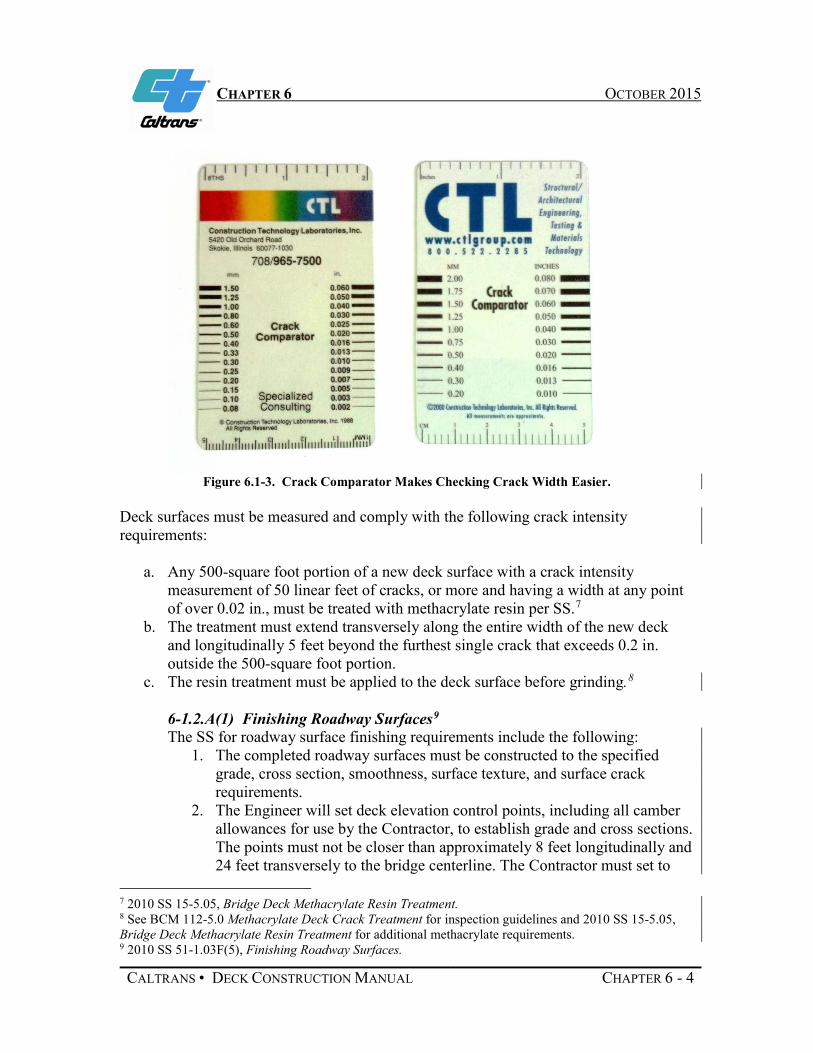
CHAPTER 6 OCTOBER 2015
Figure 6.1-3. Crack Comparator Makes Checking Crack Width Easier.
Deck surfaces must be measured and comply with the following crack intensity requirements:
a. Any 500-square foot portion of a new deck surface with a crack intensity measurement of 50 linear feet of cracks, or more and having a width at any point of over 0.02 in., must be treated with methacrylate resin per SS.7
b. The treatment must extend transversely along the entire width of the new deck and longitudinally 5 feet beyond the furthest single crack that exceeds 0.2 in. outside the 500-square foot portion.
c. The resin treatment must be applied to the deck surface before grinding.8
6-1.2.A(1) Finishing Roadway Surfaces9
The SS for roadway surface finishing requirements include the following: 1. The completed roadway surfaces must be constructed to the specified
grade, cross section, smoothness, surface texture, and surface crack requirements.
2. The Engineer will set deck elevation control points, including all camber allowances for use by the Contractor, to establish grade and cross sections. The points must not be closer than approximately 8 feet longitudinally and 24 feet transversely to the bridge centerline. The Contractor must set to
7 2010 SS 15-5.05, Bridge Deck Methacrylate Resin Treatment. 8 See BCM 112-5.0 Methacrylate Deck Crack Treatment for inspection guidelines and 2010 SS 15-5.05, Bridge Deck Methacrylate Resin Treatment for additional methacrylate requirements. 9 2010 SS 51-1.03F(5), Finishing Roadway Surfaces.
CALTRANS • DECK CONSTRUCTION MANUAL CHAPTER 6 - 4

CHAPTER 6 OCTOBER 2015
grade all rails and headers used to support the finishing equipment, and must move all finishing equipment over the entire length of the section to be placed to check steel and bulkhead clearances before concrete placement on any deck section, as shown in Figure 6.1-4.
Figure 6.1-4. Typical Grade Rail Setup.
3. Complete the smoothness testing and any required grinding before applying seal coats.
4. Bridge decks to be covered with membrane seals will be finished to a smooth surface free of mortar ridges and other projections. The coefficient of friction requirements do not apply for these bridges decks.
6-1.2.A(B) Bridge Deck Surface Texture One of the primary sources of traffic noise is tire-pavement interface. Engineers have researched methods to reduce highway system noise impact beyond building sound barriers. Noise testing equipment is seen in Figure 6.1-5. Research has shown that traffic noise can be minimized at a minimal cost by incorporating quiet pavement strategies in construction practices. These deck surface texture practices will be covered in the Standard Specifications.10
10 2010 SS 51-1.03F(5)(b), Bridge Deck Surface Texture.
CALTRANS • DECK CONSTRUCTION MANUAL CHAPTER 6 - 5

CHAPTER 6 OCTOBER 2015
Figure 6.1-5. Typical Research Setup Quantifying Tire-Pavement Interface Noise Level.
To reduce the tire-pavement noise in noise sensitive areas, all new bridge deck projects advertised for bid after January 1, 2011, include the Standard Special Provision (SSP), Bridge Deck Surface Texture. The 2010 Standard Specification Section 51-1.03F(5)(b), which has been reserved, will include the Bridge Deck Surface Texture requirements in this section.
Standard Specifications provide the following two texturing options depending on whether or not the bridge deck or approach slab is located in a noise sensitive or non-noise sensitive area. These two methods are:
1. Longitudinal tining (see Figure 6.1-6). 2. Longitudinal grinding and grooving (see Figure 6.1-7).
For the longitudinal tining option, the specification requires that initial texturing be performed with burlap drag or a broom device that produces striations parallel to the centerline. Final texturing should be performed with spring steel tines that produce grooves parallel with the centerline.
CALTRANS • DECK CONSTRUCTION MANUAL CHAPTER 6 - 6

CHAPTER 6 OCTOBER 2015
Figure 6.1-6. Longitudinal Tining Typical Process.
For the longitudinal grinding and grooving option, the specification requires placing .25 in. of sacrificial concrete cover on the bridge deck above the finished grade.
Figure 6.1-7. Close-up of Grooving.
The following sequence must be used to perform grinding and grooving surfaces:
CALTRANS • DECK CONSTRUCTION MANUAL CHAPTER 6 - 7

CHAPTER 6 OCTOBER 2015
1. Comply with the smoothness and deck crack treatment requirements of the Standard Specifications.11
2. Grind the entire surface between the face of concrete barriers to within 18 inches of the barrier toe under Standard Specifications12. Grinding must not reduce the concrete cover on reinforcing steel to less than 1-3/4 in.
3. Groove the ground surfaces longitudinally, parallel to the centerline13 .
The Contractor may propose to the Engineer other techniques or devices to achieve the requirements of bridge longitudinal texturing. For additional information about longitudinal texturing of new bridges and approach slabs, see the Bridge Construction Records and Procedures Manual.14
6-2 Curing Bridge Decks
Proper curing of concrete deck surfaces is one of the key elements in controlling cracks. The Specifications15 require bridge decks to be cured by both the curing compound method and the water method.
The following requirements must be met for compound and water curing of bridge decks.
6-2.1 Curing Compound Method The steps for curing using the Compound Method are as follows:
1. The curing compound must be Curing Compound Number 1. 2. Apply the curing compound at a nominal rate of 150 sq ft/gal. At any point, the
application rate must be within ±50 sq ft/gal of the nominal rate. The average application rate must be within ±25 sq ft/gal of the nominal rate when tested per California Test 535.
3. Apply the curing compound in a manner that prevents runs, sags, thin areas, skips, or holidays.
4. Apply the curing compound using power-operated spraying equipment with an operational pressure gage and a means of controlling the pressure. The Engineer may allow hand-spraying for small and irregular areas that, in the Engineer’s opinion, are not reasonably accessible to power-operated spraying.
5. Apply the curing compound to the finished concrete surface immediately before the moisture sheen disappears from the concrete surface, but before drying shrinkage or craze cracks start to appear (see Figure 6.2-1).
6. If the film of curing compound is damaged before the expiration of seven days
11 2010 SS 51-1.01D(4), Testing Roadway Surfaces. 12 2010 SS 42-3, Grinding. 13 2010 SS 42-2, Grooving. 14 BCM 112-6.0 Quieter Bridge Deck Construction. 15 2010 SS 51-1.03H, Curing Concrete Structures and 2010 SS 90-1.03B, Curing Concrete.
CALTRANS • DECK CONSTRUCTION MANUAL CHAPTER 6 - 8

CHAPTER 6 OCTOBER 2015
after the concrete is placed, immediately apply additional compound.
Figure 6.2-1. Applying Spray Cure from a Moveable Bridge Following the Finishing Machine.
6-2.2 Curing Water Method 1. Concrete must be kept continuously wet by applying water for a curing period of
at least seven days after the concrete is placed.A curing medium such as cotton mats, rugs, carpets, or earth or sand blankets, may be used to retain moisture during the curing period.
2. Keep the concrete surface damp by applying water with an atomizing nozzle (fogging) that forms a mist and not a spray until the surface is covered with the curing medium (Figure 6.2-2). Do not apply the water under pressure directly on the concrete or allow the water to flow over or wash the concrete surface.
Figure 6.2-2. Misting Cure Medium.
CALTRANS • DECK CONSTRUCTION MANUAL CHAPTER 6 - 9

CHAPTER 6 OCTOBER 2015
Other requirements include: 1. Maintain concrete at a temperature of not less than 45°F for 72 hours after the
pour, and at not less than 40°F for an additional four days. 2. For each batch of curing compound delivered to the job site, the Contractor must
submit curing test samples to Materials Engineering and Testing Services (METS). Samples must be from the shipping containers at the Manufacturer’s source of supply. A Certificate of Compliance must be submitted to the Engineer and to METS.
For additional information about curing bridge deck surfaces, see Bridge Construction Records and Procedures Memo 105-3.0 thru 105-5.0 and Chapter 5 of the Concrete Technology Manual.
CALTRANS • DECK CONSTRUCTION MANUAL CHAPTER 6 - 10

ACKNOWLEDGEMENTS OCTOBER 2015
Acknowledgements The 2015 edition of the Bridge Deck Construction Manual was updated by a group of dedicated Bridge Engineers from the Structure Construction Bridge Deck and Barrier Rail Technical Team.
Thanks to Steve Harvey, P.E., Supervising Bridge Engineer, for his sponsorship of the Bridge Deck and Rail Technical Team. His guidance and leadership proved invaluable towards the successful updating of this manual. Thanks to Senior Bridge Engineers Loren Newell, P.E. and Sonny Fereira, P.E. for their dedicated contributions and teamwork as Technical Team Chairman and Vice-Chairman. Thanks to the Senior Bridge Engineer team members David Tenorio, P.E., Monty Navarro, P.E., and Richard Yates, P.E. for their help updating chapters and Bridge Construction Memos. Thanks to Structure Representative and team members David Clark, P.E., and Steve Elkins, P.E., for their input on current field practices, manual edits and compilation of jobsite photographs. The entire Bridge Deck and Rail Technical Team are to be applauded for their efforts.
Thanks to Senior Bridge Engineer Cheryl Poulin, P.E. for her tireless efforts towards keeping this team on track and supplying them with tools necessary to update this manual. Thanks to Marty Cook, AGPA, for assembling the manual in a readable format while keeping it in conformance with a writing style consistent with Structure Construction practices.
Special thanks to the Caltrans engineers who drafted the original 1991 Bridge Deck Construction Manual. Their vision, dedication, and research, produced a manual that has been used by many throughout the years.
Signed,
STEVE ALTMAN Deputy Division Chief Structure Construction Division of Engineering Services
CALTRANS • DECK CONSTRUCTION MANUAL ACKNOWLEDGEMENTS