bridge chapter 04
TRANSCRIPT

8/12/2019 Bridge Chapter 04
http://slidepdf.com/reader/full/bridge-chapter-04 1/24
4 Concrete PlacementClasses of Structural Concrete
Concrete Plant Inspection
Types of Plants
Plant Technician
Preparations for Concrete Placement
Plan Review Site
Preparations
Weather Restrictions
Concrete Delivery
Delivery Equipment
Delivery Tickets
Field Tests
Recording Test Results
Concrete Placement
Segregation
Consolidation of Concrete
Construction oints Special Cases
Finishing Concrete Surfaces
!inishing "earing #reas
$ther Surface Treatments

8/12/2019 Bridge Chapter 04
http://slidepdf.com/reader/full/bridge-chapter-04 2/24
Curing Substructure Concrete
Cold Water Curing
Method of Measurement and Basis for Payment

8/12/2019 Bridge Chapter 04
http://slidepdf.com/reader/full/bridge-chapter-04 3/24
C!PT"# F$%#&
C$%CRETE P&#CE'E%T
The major topics to be discussed in this chapter are:
1) Classes of concrete
2) Concrete plants
3) Preparations for concrete delivery
4) Field tests
) Concrete placement
!) Concrete finishin"
#) Curin" methods
Technicians are re$uired to have a basic %no&led"e of concrete used in
brid"e construction and the plants that produce the concrete' (uch an
understandin" helps to form a cooperative relationship bet&een the
Technicians at the plant and the Technicians in the field'
C'!SS"S $F ST#%CT%#!' C$(C#"T"
(tructural concrete is produced as Class * Class +* and Class C' The
differences bet&een the classes are in the cement and a""re"ate contents
and &ater,cementitious ratios'
+rid"e construction often re$uires the use of all three classes of concrete'
For e-ample* the plans may re$uire Class + concrete for the footin"s*
Class for the piers and bents* and Class C for the dec%s and railin"s' The
.otes section of the /eneral Plan sheet lists the classes of concrete to beused' The +ill of 0aterials section on the detail sheets also lists these
classes' n most cases* the Contractor may substitute Class C concrete for
Class concrete and Class or Class C concrete for Class + concrete'
41

8/12/2019 Bridge Chapter 04
http://slidepdf.com/reader/full/bridge-chapter-04 4/24
The materials used in the production of structural concrete include
combinations of the follo&in":
1) Fine and coarse a""re"ates
2) Portland cement
3) Fly ash a coal byproduct)
4) ater
) dmi-tures* includin" retarders* accelerators* &ater
reducers* and air entrainin" a"ents
C$(C#"T" P'!(T I(SP"CTI$(
T(PES $! P&#%TS
.56T cate"ori7es concrete plants as captive plants or commercial
plants' Captive plants are usually temporary plants constructed on the
jobsite) and are used primarily to produce concrete for a specific
contract' hen the contract is finished* the plant is disassembled and
moved' Commercial plants Fi"ure 41)* on the other hand* are
permanent installations'
Figure 4)*+ Commercial Plant
42

8/12/2019 Bridge Chapter 04
http://slidepdf.com/reader/full/bridge-chapter-04 5/24
Concrete plants are inspected and certified by the 6ffice of 0aterials
0ana"ement' Commercial plants are inspected once a year' Captive plants
are inspected at the be"innin" of each construction season and &henever
they are moved to a ne& location'
P&#%T TEC)%*C*#%
There are t&o reasons for havin" Technicians at concrete plants' The first
is to insure that .56T receives the $uality of materials the Contractor
has a"reed to supply* and the second is to insure those materials are
delivered in the proper $uantities'
Plant Technicians are responsible for observin" all &ei"hin"* batchin"*
and mi-in" operations* e-cept &hen mi-in" ta%es place a&ay from the
plant site' Technicians are re$uired to ensure that all materials have been
sampled* tested* and approved' The plant scales used for batchin" cement
and a""re"ates are re$uired to be chec%ed for accuracy t&ice a day'
Plant Technicians are re$uired to maintain a cooperative relationship &ith
the Contractor and plant personnel' +ein" prepared for &or% and %no&in"
the re$uirements for the concrete are necessary to maintain this
relationship'
P#"P!#!TI$(S F$# C$(C#"T" P'!C"M"(T
The smooth delivery of concrete to the jobsite is critical' 5elays in the
delivery of the concrete or durin" the placement operation may cause
problems that are time consumin" and costly to resolve' The fieldTechnician* the Contractor* and the concrete plant Technician are re$uired
to &or% to"ether to ensure the correct concrete is delivered on time and in
the necessary $uantities'
P&#% RE+*EW
Preparin" for the delivery of concrete be"ins &ith a revie& of the plans'
The class or classes of concrete are re$uired to be chec%ed' The +ill of
0aterials section of the detail sheets is used to locate the estimated
$uantities for each class of concrete' (ubstitutions of a hi"her class of
concrete are "enerally allo&ed8 ho&ever* the Contractor is never permittedto substitute an inferior class of concrete for the class of concrete re$uired
in the plans'
The detail sheets also provide important information concernin" the
concrete pour* such as the pour se$uence and the locations and dimensions
of the construction joints and %ey&ays'
43

8/12/2019 Bridge Chapter 04
http://slidepdf.com/reader/full/bridge-chapter-04 6/24
S*TE PREP#R#T*$%S
The Technician is re$uired to ensure that the site has been ade$uately
prepared for concrete placement' (uch preparations include that:
1) 9-cavations have been de&atered
2) Forms have been chec%ed for ade$uate bracin" and proper
elevations and ali"nment
3) Chamfer strips have been installed and are in "ood shape
4) Trash and debris have been removed from all forms
) einforcement has been tied securely and chec%ed for
proper clearance and spacin"
!) The Contractor has ade$uate manpo&er and e$uipment to
handle the pour to include a sufficient number of
vibrators and bac%ups'
WE#T)ER RESTR*CT*$%S
The Technician is re$uired to %no& the &eather forecast for the concrete
placement operation' eather conditions may influence everythin" from
the timin" and method of concrete delivery and placement to postponin"
the operation alto"ether' deally* concrete is placed in temperatures
bet&een ; and <;= F* &hen there is no threat of rain* and &hen steps have been ta%en to protect the concrete from e-cessive &ind'
n "eneral* &hen the temperature is 3= F or belo&* the temperature of the
concrete is re$uired to be bet&een ; and >;= F at the time of placin"' The
Contractor may heat the &ater and,or a""re"ates used in the concrete mi-
to achieve this ran"e of temperatures8 ho&ever* the heatin" is re$uired to
be done in accordance &ith the (pecifications for cold&eather concrete'
The Technician is re$uired to use a dial thermometer to chec% the concrete
temperature &henever the concrete is suspected to be near the
(pecifications limits'
C$(C#"T" D"'I,"#-
.o concrete may be placed &ithout a Technician on the job and another
Technician at the concrete plant' Prior to the be"innin" of concrete
delivery* the Technician is re$uired to contact the plant Technician to
doublechec% the follo&in" items:
44

8/12/2019 Bridge Chapter 04
http://slidepdf.com/reader/full/bridge-chapter-04 7/24
1) The class of concrete to be used
2) The $uantity of concrete needed for the pour
3) The slump and air content re$uirements
4) The proposed startin" time of delivery
) The desired rate of delivery'
DE&*+ER( E,-*P'E%T
Concrete is typically delivered to the job site in mi-er truc%s* a"itator
truc%s* or in nona"itatin" e$uipment' ll delivery truc%s are re$uired to
comply &ith the e$uipment (pecifications desi"nated in (ection ./0+
0i-er truc%s Fi"ure 42) are desi"ned for mi-in" concrete at or on the&ay to the job site' For this reason* mi-er truc%s al&ays have a &ater tan%
on board and a measurin" device that is capable of controllin" the amount
of &ater that is added to the mi-' "itator truc%s deliver readymi-ed
concrete' ny &ater on the truc% is for cleanin" purposes only* not for
mi-in"'
Figure 4)0+ Mi1er Truc2s
4
8/12/2019 Bridge Chapter 04
http://slidepdf.com/reader/full/bridge-chapter-04 8/24
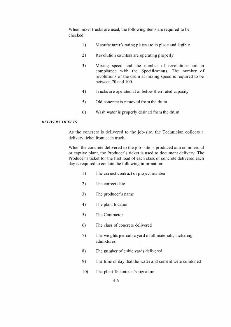
hen mi-er truc%s are used* the follo&in" items are re$uired to be
chec%ed:
1) 0anufacturer?s ratin" plates are in place and le"ible
2) evolution counters are operatin" properly
3) 0i-in" speed and the number of revolutions are in
compliance &ith the (pecifications' The number of
revolutions of the drum at mi-in" speed is re$uired to be
bet&een #; and 1;;'
4) Truc%s are operated at or belo& their rated capacity
) 6ld concrete is removed from the drum
!) ash &ater is properly drained from the drum
DE&*+ER( T*C.ETS
s the concrete is delivered to the jobsite* the Technician collects a
delivery tic%et from each truc%'
hen the concrete delivered to the job site is produced at a commercial
or captive plant* the Producer?s tic%et is used to document delivery' The
Producer?s tic%et for the first load of each class of concrete delivered each
day is re$uired to contain the follo&in" information:
1) The correct contract or project number
2) The correct date
3) The producer?s name
4) The plant location
) The Contractor
!) The class of concrete delivered
#) The &ei"hts per cubic yard of all materials* includin"
admi-tures
>) The number of cubic yards delivered
<) The time of day that the &ater and cement &ere combined
1;) The plant Technician?s si"nature
4!

8/12/2019 Bridge Chapter 04
http://slidepdf.com/reader/full/bridge-chapter-04 9/24
fter the first load is delivered* the Producer?s name* the plant
location* the Contractor* and the &ei"hts of the various materials
used in batchin" may be omitted from the Producer?s tic%ets for
the rest of the day or until the mi- desi"n is chan"ed' f the mi-
desi"n is chan"ed* the tic%et for the first load of the revised mi- is
re$uired to indicate all chan"es'
FI"'D T"STS
Conductin" and,or observin" concrete field tests is one of the most
important duties of a Technician' Typical field tests include slump*
air content* yield* and &ater,cementitious ratio' The e$uipment
used to conduct the tests is re$uired to be clean* in "ood shape* and
capable of providin" accurate results' The air meters Fi"ure 4 3)
used in air content tests and the scales used in yield tests are
re$uired to be calibrated and approved' ll test e$uipment is
provided by 5istrict Testin"'
Figure 4)3+ !ir Content Meter
The procedures for conductin" slump* air content* fle-ural
stren"th* and yield tests are detailed in the .56T /eneral
nstructions to Field 9mployees' The re$uired fre$uency for
conductin" all tests is listed in the Fre$uency 0anual' That
fre$uency of tests listed* ho&ever* is a minimum and may be
increased as specified by the plans* the (pecial Provisions* or by
the P9,P(' The follo&in" is a brief description of the purpose of

8/12/2019 Bridge Chapter 04
http://slidepdf.com/reader/full/bridge-chapter-04 10/24
each test'
4#

8/12/2019 Bridge Chapter 04
http://slidepdf.com/reader/full/bridge-chapter-04 11/24
(lump tests are conducted to determine the consistency of fresh
concrete and to chec% the uniformity of concrete from batch to
batch' Typical specification limits for slump for structural concrete
are bet&een 1 and 4 in' @nacceptable slump measurements usually
indicate improper mi- proportions* especially the &ater content'Contractors are not permitted to add &ater simply to ma%e the mi-
easier to pour' ny such chan"e to the mi- desi"n re$uires prior
approval'
ir content tests are conducted to determine ho& much air is
contained in the concrete' n most cases* air has been purposely
added or entrained in concrete to ma%e the concrete more durable'
llo&able air content may ran"e from to > A* dependin" on the
ma-imum si7e of the a""re"ates used in the mi-' esults outside
the specified limits indicate a re$uirement to adjust the amount of
admi-ture in subse$uent batches'
Bield tests are conducted to determine the &ei"ht per cubic foot of
fresh concrete &hich is used to determine the cement in barrels per
cubic yard' Bield tests are not used to chec% the batchin" of any
one mi- component'
Fle-ural stren"th is conducted to determine &hen forms and,or
false&or% may be removed from a structure or to determine &hen a
structure may be put into service' This test re$uires placin" fresh
concrete in a beam mold and allo&in" the concrete to set and cure
under the same conditions as the concrete used in the structure'
The concrete is then removed from the mold and bro%en in a
controlled environment by a beam brea%er' The test results may
then be used to ma%e certain assumptions re"ardin" the stren"th of
the concrete used in the structure'
ater,cementitious ratio is the ratio of the total amount of free
&ater in the a""re"ates* includin" all free &ater in the concrete* to
the amount of cement in the concrete'
REC$RD*%/ TEST RES-&TS
The results of the slump* air content* and yield tests are recordedand submitted on Form T !2' Fle-ural stren"th tests are
documented on Form T #1* and &ater,cementitious ratio is
recorded on Form T !2>'
C$(C#"T" P'!C"M"(T
Compared to the preparations leadin" up to the pour and the
testin"* the actual placement operation is relatively simple8
ho&ever* there are still items that may "o &ron"'

8/12/2019 Bridge Chapter 04
http://slidepdf.com/reader/full/bridge-chapter-04 12/24
4>

8/12/2019 Bridge Chapter 04
http://slidepdf.com/reader/full/bridge-chapter-04 13/24
SE/RE/#T*$%
(e"re"ation occurs &hen the coarse and fine a""re"ates used in the
concrete separate and become unevenly distributed throu"hout the mi-'
The lar"er coarse a""re"ate sin%s to the bottom &hile the fines rise to the
top' (e"re"ation al&ays leads to an inferior $uality of concrete' For the
most part* ho&ever* se"re"ation may be prevented &ith the use of proper
placement e$uipment and techni$ues'
Concrete is re$uired to be placed as close as possible to the location the
concrete occupies in the structure' The concrete should not be dumped in a
central location and then spread to the location re$uired in the structure
Fi"ure 44)'
Figure 4)4+ Concrete Placement
hen possible* concrete is re$uired to be deposited in layers no more than
24 in' thic% Fi"ure 4)' Care is re$uired be ta%en* ho&ever* to place each
successive layer before the precedin" layer has ta%en the initial set' Thisinitial set is usually 4 minutes to an hour* dependin" on the temperature'
Too much time bet&een the placement of layers usually results in a cold
joint &hich is a &ea% line of separation bet&een the layers'
Figure 4)+ Concrete 'ayers
4<

8/12/2019 Bridge Chapter 04
http://slidepdf.com/reader/full/bridge-chapter-04 14/24
5roppin" concrete from too "reat a hei"ht causes the finer particles in the
mi- to splash a&ay from the lar"er* heavier particles' n addition* the force
of the mi- stri%in" the reinforcin" steel may shift bars out of position' The
ma-imum drop hei"ht or allo&able free fall is ft' oppers &ith fle-ible
chutes called tremies are re$uired to be used to funnel the mi- do&n into
tall* narro& forms' or%ers may be stationed inside the forms to move thechutes around to ensure an even distribution of the concrete' The hoppers
may not rest on the reinforcin" steel and are re$uired to be supported by
the form&or%'
C$%S$&*D#T*$% $! C$%CRETE
Fresh concrete naturally contains air poc%ets or voids' f the concrete &ere
left that &ay* the finished product &ould have a rou"h surface and have
$uestionable stren"th' To eliminate voids and to ensure a "ood bond to the
reinforcin" steel* the concrete is re$uired to be consolidated to a uniform
density'
The most common method of consolidatin" concrete is by vibratin" the
concrete &ith a portable spud type vibrator Fi"ure 4!)' 0ost vibrators
have an effective radius of 1> in' all around' 6nce the vibrators are
inserted* they consolidate an area appro-imately 3 ft in diameter'
Figure 4)5+ Spud ,ibrator
41;

8/12/2019 Bridge Chapter 04
http://slidepdf.com/reader/full/bridge-chapter-04 15/24
lthou"h the procedure is a simple operation* vibratin" concrete is often
conducted incorrectly' (ome points that ensure a "ood job include:
1) Dibratin" is re$uired to be done immediately as the
concrete is placed
2) Dibrators are re$uired to be inserted and &ithdra&n
vertically and should not be dra""ed throu"h the concrete
3) Dibrators are re$uired to be inserted and &ithdra&n &ithin
seconds' 6vervibratin" forces the finer a""re"ates to the
top and drives the lar"er a""re"ates to&ard the bottom'
4) hen concrete is poured in layers* the head of the vibrator
is re$uired to penetrate throu"h the top layer and partially
throu"h the layer underneath Fi"ure 4#)'
Figure 4).+ Depth of ,ibration
) The &or%ers are re$uired to avoid contactin" thereinforcin" steel &ith the vibrator so that the bond bet&een
the steel and the concrete is not bro%en
!) The &or%ers are re$uired to avoid contactin" the form
&alls &ith the vibrator as that may loosen the forms and
may also cause honeycombin" of the concrete surface
#) The Contractor is re$uired to have a bac%up vibrator on
hand for lar"er pours in case of e$uipment problems
C$%STR-CT*$% $*%TS
The purpose of a construction joint is to join a section of fresh concrete to
a previously poured section that has already set' Construction joints are
necessary &hen a substructure unit is too lar"e to pour in one continuous
operation or &hen rain* e$uipment problems* or other conditions interrupt
the pour' @nless construction joints are specifically called for on the plans*
the Contractor is re$uired to have &ritten permission to use the
411

8/12/2019 Bridge Chapter 04
http://slidepdf.com/reader/full/bridge-chapter-04 16/24
joints' (ome joints* ho&ever* may be described on the plans as optional*
and may be used at the Contractor?s discretion' n addition* the Contractor
may re$uest the relocation or elimination of construction joints' (uch a
chan"e is re$uired to be approved by the P9,P('
To ma%e a construction joint* either planned or unplanned* the Contractoris re$uired to form a raised %ey&ay or %ey&ays in the section to be poured
later' fter the first section has hardened* the surface is s&ept clean &ith
&ire brooms and %ept &et' f a Type construction joint is specified
Fi"ure 4>)* the surface is notched bet&een the reinforcement'
mmediately before the fresh concrete is placed* the Contractor dra&s the
forms up ti"ht a"ainst the concrete in place' To improve the bond bet&een
the sections* the Contractor may apply a bondin" epo-y to the e-posed
surface before resumin" the pour'

8/12/2019 Bridge Chapter 04
http://slidepdf.com/reader/full/bridge-chapter-04 17/24
Figure 4)6+ Type ! Construction 7oint
To resist shear and other forces* construction joints in footin"s and inabutments for arch brid"es are re$uired to be vertical' ori7ontal
construction joints are used in &alls and columns' Eoints that are e-posed
to vie& are re$uired to be constructed strai"ht* clean* and &aterti"ht' This
is done by finishin" the concrete &ith the underside of a strai"ht
412
8/12/2019 Bridge Chapter 04
http://slidepdf.com/reader/full/bridge-chapter-04 18/24
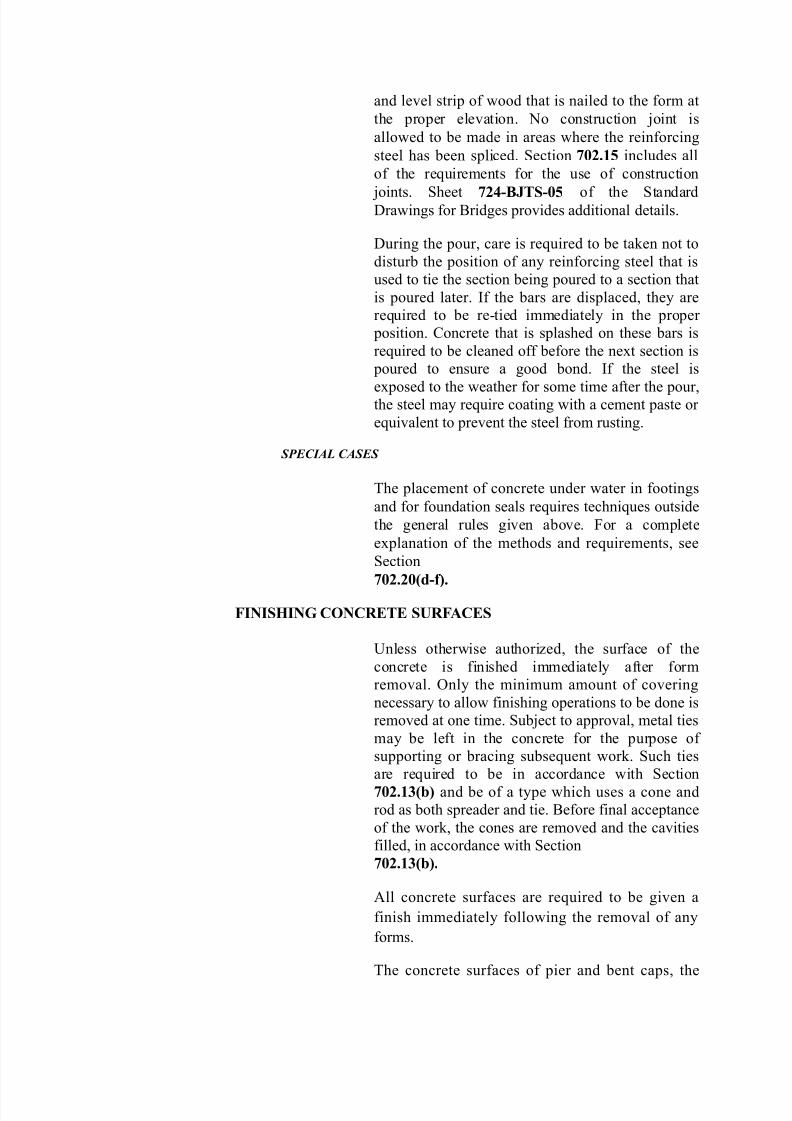
and level strip of &ood that is nailed to the form at
the proper elevation' .o construction joint is
allo&ed to be made in areas &here the reinforcin"
steel has been spliced' (ection ./0+* includes all
of the re$uirements for the use of construction
joints' (heet .04)B7TS)/ of the (tandard5ra&in"s for +rid"es provides additional details'
5urin" the pour* care is re$uired to be ta%en not to
disturb the position of any reinforcin" steel that is
used to tie the section bein" poured to a section that
is poured later' f the bars are displaced* they are
re$uired to be retied immediately in the proper
position' Concrete that is splashed on these bars is
re$uired to be cleaned off before the ne-t section is
poured to ensure a "ood bond' f the steel is
e-posed to the &eather for some time after the pour*the steel may re$uire coatin" &ith a cement paste or
e$uivalent to prevent the steel from rustin"'
SPEC*#& C#SES
The placement of concrete under &ater in footin"s
and for foundation seals re$uires techni$ues outside
the "eneral rules "iven above' For a complete
e-planation of the methods and re$uirements* see
(ection
./0+0/8d)f9+
FI(ISI(: C$(C#"T" S%#F!C"S
@nless other&ise authori7ed* the surface of the
concrete is finished immediately after form
removal' 6nly the minimum amount of coverin"
necessary to allo& finishin" operations to be done is
removed at one time' (ubject to approval* metal ties
may be left in the concrete for the purpose of
supportin" or bracin" subse$uent &or%' (uch ties
are re$uired to be in accordance &ith (ection
./0+*38b9 and be of a type &hich uses a cone and
rod as both spreader and tie' +efore final acceptance
of the &or%* the cones are removed and the cavities
filled* in accordance &ith (ection
./0+*38b9+
ll concrete surfaces are re$uired to be "iven a
finish immediately follo&in" the removal of any
forms'
The concrete surfaces of pier and bent caps* the

8/12/2019 Bridge Chapter 04
http://slidepdf.com/reader/full/bridge-chapter-04 19/24
front face of mud&alls* and any other concrete
surfaces specified are re$uired to be sealed' The
material used for sealin" is re$uired to be in
accordance &ith (ection ./;' The seal is applied to
obtain a finished film thic%ness of at least 2; m
1; mils)' 0i-in"* surface preparation* and themethod of application are re$uired to be in
accordance &ith the manufacturerGs
recommendations8 ho&ever* the surfaces to be
sealed are prepared in accordance &ith (ection ./;
prior to applyin" the sealer'
413

8/12/2019 Bridge Chapter 04
http://slidepdf.com/reader/full/bridge-chapter-04 20/24
t the time of the removal of forms* the concrete surface is scraped to
remove all fins and irre"ular projections' The surface is then po&er "round
to smooth all joints and chamfers'
fter "rindin" is completed* a paste of "rout is applied to the concrete
surface &ith a spon"e float to fill all air holes and small irre"ularities' The
paste "rout is re$uired to be ! parts of premi- mortar mi- for masonry
and 1 part &hite portland cement in accordance &ith !STM C)*/* Type
1'
fter the paste "rout ta%es the initial set* the surface of the concrete is
scraped &ith a steel dry&all %nife to remove the paste from the surface'
!*%*S)*%/ "E#R*%/ #RE#S
The brid"e seats and areas in bet&een re$uire special treatment at the
finishin" sta"e' The tops of the brid"e seats are re$uired to be finished ate-actly the ri"ht elevation and be completely level to ensure full contact
&ith the bottom of the bearin" device' The areas in bet&een the brid"e
seats are re$uired to be sloped or cro&ned sli"htly to ensure ade$uate
surface draina"e' +oth results are obtained throu"h proper finishin"
techni$ues'
$T)ER S-R!#CE TRE#T'E%TS
The plans or (pecial Provisions may provide for the use of surface
treatments other than the three classes of concrete finishes' For e-ample*
the plans may re$uire the Contactor to leave a rou"h surface te-ture ofe-posed a""re"ate' This may be done by blastin" off the surface mortar
&ith a hi"hpressure &ater hose'
The surfaces of pier and bent caps* the front face of mud&alls* and any
other areas specified are re$uired to be sealed a"ainst moisture penetration
&ith an approved concrete sealer' The surfaces to be sealed are
sandblasted to remove form oil and other forei"n matter and are re$uired
to be completely dry before the application' The sealant is applied in a
crisscross pattern and is re$uired to be a thic%ness of 1; mils' .o sealed
surface is rubbed' (ection ./; describes this operation in detail'
414
8/12/2019 Bridge Chapter 04
http://slidepdf.com/reader/full/bridge-chapter-04 21/24
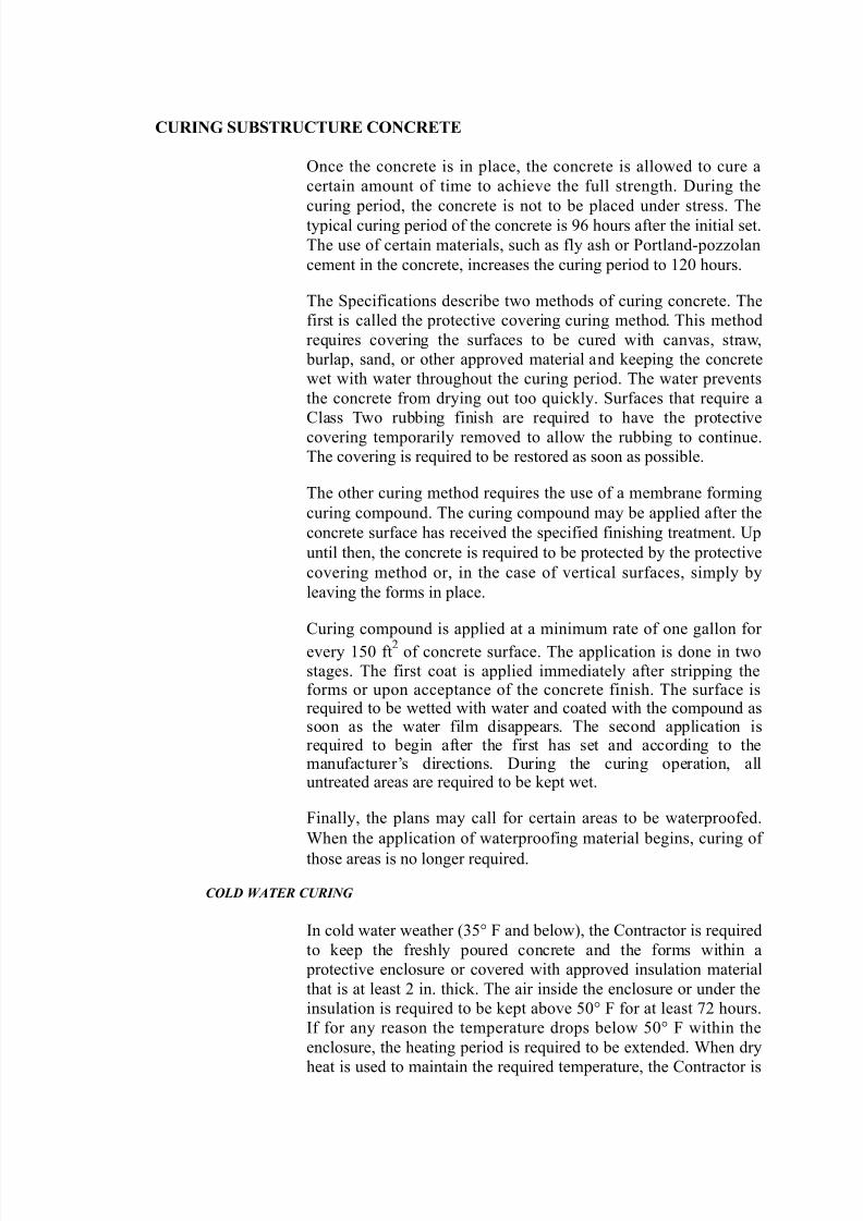
C%#I(: S%BST#%CT%#" C$(C#"T"
6nce the concrete is in place* the concrete is allo&ed to cure a
certain amount of time to achieve the full stren"th' 5urin" the
curin" period* the concrete is not to be placed under stress' Thetypical curin" period of the concrete is <! hours after the initial set'
The use of certain materials* such as fly ash or Portlandpo77olan
cement in the concrete* increases the curin" period to 12; hours'
The (pecifications describe t&o methods of curin" concrete' The
first is called the protective coverin" curin" method' This method
re$uires coverin" the surfaces to be cured &ith canvas* stra&*
burlap* sand* or other approved material and %eepin" the concrete
&et &ith &ater throu"hout the curin" period' The &ater prevents
the concrete from dryin" out too $uic%ly' (urfaces that re$uire a
Class T&o rubbin" finish are re$uired to have the protective
coverin" temporarily removed to allo& the rubbin" to continue'
The coverin" is re$uired to be restored as soon as possible'
The other curin" method re$uires the use of a membrane formin"
curin" compound' The curin" compound may be applied after the
concrete surface has received the specified finishin" treatment' @p
until then* the concrete is re$uired to be protected by the protective
coverin" method or* in the case of vertical surfaces* simply by
leavin" the forms in place'
Curin" compound is applied at a minimum rate of one "allon for
every 1; ft2 of concrete surface' The application is done in t&osta"es' The first coat is applied immediately after strippin" theforms or upon acceptance of the concrete finish' The surface isre$uired to be &etted &ith &ater and coated &ith the compound assoon as the &ater film disappears' The second application isre$uired to be"in after the first has set and accordin" to themanufacturer?s directions' 5urin" the curin" operation* alluntreated areas are re$uired to be %ept &et'
Finally* the plans may call for certain areas to be &aterproofed'
hen the application of &aterproofin" material be"ins* curin" of
those areas is no lon"er re$uired'
C$&D W#TER C-R*%/
n cold &ater &eather 3= F and belo&)* the Contractor is re$uired
to %eep the freshly poured concrete and the forms &ithin a
protective enclosure or covered &ith approved insulation material
that is at least 2 in' thic%' The air inside the enclosure or under the
insulation is re$uired to be %ept above ;= F for at least #2 hours'
f for any reason the temperature drops belo& ;= F &ithin the
enclosure* the heatin" period is re$uired to be e-tended' hen dry
heat is used to maintain the re$uired temperature* the Contractor is

8/12/2019 Bridge Chapter 04
http://slidepdf.com/reader/full/bridge-chapter-04 22/24
re$uired to devise a means of providin" enou"h moisture
41

8/12/2019 Bridge Chapter 04
http://slidepdf.com/reader/full/bridge-chapter-04 23/24
in the air &ithin the enclosure to prevent the concrete from dryin"
out too $uic%ly' eaters may be used to maintain the re$uired
temperature if they provide continuous operation and the
Contractor has ta%en ade$uate fireprevention and safety measures'
hen rubbin" the concrete is re$uired* the forms are removed andthe rubbin" conducted durin" the protection period' "ain* if this
means that the concrete is e-posed to temperatures belo& ;= F
before the re$uired #2 hours has transpired* the period of
protection and heatin" is re$uired to be e-tended'
M"T$D $F M"!S%#"M"(T !(D B!SIS F$# P!-M"(T
Concrete is measured and paid for by the cubic yard placed in
accordance &ith the plans or as directed' Forms* false&or%* and
other miscellaneous items re$uired to complete the &or% are not
paid for separately' The costs for these items are included in thecosts of the concrete'

8/12/2019 Bridge Chapter 04
http://slidepdf.com/reader/full/bridge-chapter-04 24/24
41!