bre global test report - d+b facades€¦ · bre global test report bs 8414-1:2015 + a1:2017 test...
TRANSCRIPT

Commercial in Confidence © BRE Global Ltd 2017 Page 1 of 36 BRE Global Test Report
BS 8414-1:2015 + A1:2017 test on d+b facades rain screen cladding system with 100mm-thick Rockwool insulation and aluminium cassette panels.
Prepared for: d+b facades (UK) Ltd. Date: 1st December 2017 Report Number: P109241-1000 Issue: 1 BRE Global Ltd Watford, Herts WD25 9XX Customer Services 0333 321 8811 Prepared for: d+b facades (UK) Ltd. The Packway, Larkhill, Salisbury, SP4 8PY

BS 8414-1 Test on d+b facades System Panel. Report Number: P109241-1000 Issue 1
Commercial in Confidence © BRE Global Ltd 2017 Page 1 of 36 This report is made on behalf of BRE Global and may only be distributed in its entirety, without amendment, and with attribution to BRE Global Ltd to the extent permitted by the terms and conditions of the contract. Test results relate only to the specimens tested. BRE Global has no responsibility for the design, materials, workmanship or performance of the product or specimens tested. This report does not constitute an approval, certification or endorsement of the product tested and no such claims should be made on websites, marketing materials, etc. Any reference to the results contained in this report should be accompanied by a copy of the full report, or a link to a copy of the full report. BRE Global’s liability in respect of this report and reliance thereupon shall be as per the terms and conditions of contract with the client and BRE Global shall have no liability to third parties to the extent permitted in law. Opinions and interpretations expressed herein are outside the scope of UKAS Accreditation. Prepared by Name David Farrington Position Fire Testing Manager Date 01 December 2017 Signature Authorised by Name Stephen Howard Position Director of Fire Testing and Certification Date 01 December 2017 Signature

BS 8414-1 Test on d+b facades System Panel. Report Number: P109241-1000 Issue 1
Commercial in Confidence © BRE Global Ltd 2017 Page 2 of 36
Table of Contents
1 Introduction 3 2 Test Details 4 3 Details of Test Apparatus 5 4 Description of the System 6 4.1 Summary 6 4.2 Description of product 6 4.3 Installation sequence 7 4.1 Conditioning of the specimen 8 5 Test Results 8 5.1 Test conditions 8 5.2 Temperature profiles 8 5.3 Visual observations 9 6 Post-Test Damage Report 11 6.1 Aluminium panels 11 6.2 Top hat section rail 11 6.3 Mineral wool insulation 11 6.4 Horizontal (compression) cavity barriers 12 6.5 Vertical (compression) cavity barrier 12 7 Conclusion 12 8 Reference 13 9 Figures 14 9.1 Diagrams of finished face of the cladding system 14 9.2 Installation photographs 16 9.3 System drawings 21 9.4 Temperature data 27 9.5 Post-test photographs 31

BS 8414-1 Test on d+b facades System Panel. Report Number: P109241-1000 Issue 1
Commercial in Confidence © BRE Global Ltd 2017 Page 3 of 36
1 Introduction The test method, BS8414 Part 1:2015 + A1:2017 [1] describes a method of assessing the behaviour of non-load bearing external cladding systems, rain screen over cladding systems and external wall insulation systems when applied to the face of a building and exposed to an external fire under controlled conditions. The fire exposure is representative of an external fire source or a fully developed (post-flashover) fire in a room, venting through an opening such as a window aperture that exposes the cladding to the effects of external flames. The specification and interpretation of fire test methods is the subject of on-going development and refinement. Changes in associated legislation may also occur. For these reasons it is recommended that the relevance of test reports over 5 years old should be considered by the user. The laboratory that issued the report will be able to offer, on behalf of the legal owner, a review of the procedures adopted for a particular test to ensure that they are consistent with current practices, and if required may endorse the test report. BRE was not involved in the design, installation, procurement or specification of the materials and cladding system that was submitted for testing. The tested system was defined by the Test Sponsor. All measurements quoted in this report are nominal unless stated otherwise.

BS 8414-1 Test on d+b facades System Panel. Report Number: P109241-1000 Issue 1
Commercial in Confidence © BRE Global Ltd 2017 Page 4 of 36
2 Test Details
Name of Laboratory: BRE Global Ltd. Laboratory Address: Bucknalls Lane, Garston, Watford, Hertfordshire. WD25 9XX Test reference: P109241-1000 Date of test: 25th September 2017 Sponsor: d+b facades (UK) Ltd. Sponsor address: The Packway, Larkhill, Salisbury, SP4 8PY Method: The test was carried out in accordance with BS 8414-1:2015 + A1:2017 Deviations: None

BS 8414-1 Test on d+b facades System Panel. Report Number: P109241-1000 Issue 1
Commercial in Confidence © BRE Global Ltd 2017 Page 5 of 36
3 Details of Test Apparatus The product was installed on to wall number 2 of the BRE Global test facility. This apparatus is representative of the face of a building and consists of a masonry structure with a vertical main test wall and a vertical return wall at a 90º angle to and at one side of the main test wall. See Figure 1. The main wall includes the combustion chamber. Figure 1. Test apparatus dimensions as specified by test Standard[1]. Note: The test apparatus may be constructed left- or right-handed.

BS 8414-1 Test on d+b facades System Panel. Report Number: P109241-1000 Issue 1
Commercial in Confidence © BRE Global Ltd 2017 Page 6 of 36
4 Description of the System
4.1 Summary
Generic cladding type Rain screen Relevant test method BS 8414-1 Substrate Masonry Insulation Rockwool RWA45 (100mm-thick) Cavity depth 140mm between insulation and facade Vertical cavity barriers Firetherm Spanatherm stone wool fire barrier (100mm-thick x 250mm-deep) Horizontal cavity barriers Firetherm Spanatherm stone wool fire barrier (100mm-thick x 250mm-deep) External finish 3mm-thick Aluminium hook-on cassette
4.2 Description of product Table 1. List of component parts used in the construction of the system Item Description 1 115mm-deep by 65mm-wide by 5mm-thick aluminium ‘U’-shaped brackets fixed with a single M12 by 150mm-long HILTI anchor bolt – see Figure 4. 2 120mm-deep by 55mm-wide (with flanges extending width to 115mm) by 7mm-thick top hat channel section aluminium rail with Ø13.5mm rods welded internally within the channel at 290mm-centres – see Figure 5. 3 100mm-thick Rockwool RWA45 insulation board (supplied 1200mm by 600mm and cut to size) – see Figure 7. 4 300mm-long by 30mm-wide ‘L’-shaped steel skewers. 5 100mm-thick by 250mm-deep horizontal and vertical cavity barriers cut from Firetherm Spanatherm foil-faced stone wool insulation boards (supplied 1200mm by 600mm). 6 3mm-thick aluminium cassette panels with edges folded back and incorporating ‘L’-shaped cut-outs with rounded edges at 290mm-centres on the vertical edges of the panel - see Figure 8.
BS 8414-1 Test on d+b facades System Panel. Report Number: P109241-1000 Issue 1
Commercial in Confidence © BRE Global Ltd 2017 Page 7 of 36
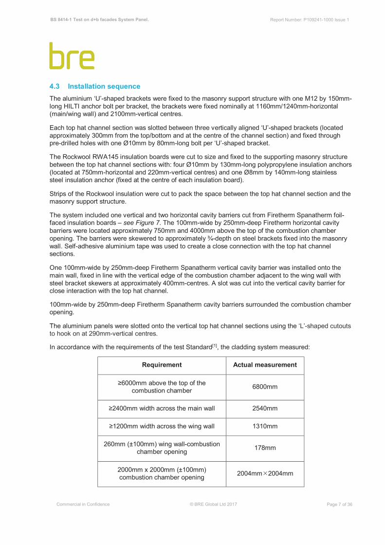
4.3 Installation sequence The aluminium ‘U’-shaped brackets were fixed to the masonry support structure with one M12 by 150mm-long HILTI anchor bolt per bracket, the brackets were fixed nominally at 1160mm/1240mm-horizontal (main/wing wall) and 2100mm-vertical centres. Each top hat channel section was slotted between three vertically aligned ‘U’-shaped brackets (located approximately 300mm from the top/bottom and at the centre of the channel section) and fixed through pre-drilled holes with one Ø10mm by 80mm-long bolt per ‘U’-shaped bracket. The Rockwool RWA145 insulation boards were cut to size and fixed to the supporting masonry structure between the top hat channel sections with: four Ø10mm by 130mm-long polypropylene insulation anchors (located at 750mm-horizontal and 220mm-vertical centres) and one Ø8mm by 140mm-long stainless steel insulation anchor (fixed at the centre of each insulation board). Strips of the Rockwool insulation were cut to pack the space between the top hat channel section and the masonry support structure. The system included one vertical and two horizontal cavity barriers cut from Firetherm Spanatherm foil-faced insulation boards – see Figure 7. The 100mm-wide by 250mm-deep Firetherm horizontal cavity barriers were located approximately 750mm and 4000mm above the top of the combustion chamber opening. The barriers were skewered to approximately ¾-depth on steel brackets fixed into the masonry wall. Self-adhesive aluminium tape was used to create a close connection with the top hat channel sections. One 100mm-wide by 250mm-deep Firetherm Spanatherm vertical cavity barrier was installed onto the main wall, fixed in line with the vertical edge of the combustion chamber adjacent to the wing wall with steel bracket skewers at approximately 400mm-centres. A slot was cut into the vertical cavity barrier for close interaction with the top hat channel. 100mm-wide by 250mm-deep Firetherm Spanatherm cavity barriers surrounded the combustion chamber opening. The aluminium panels were slotted onto the vertical top hat channel sections using the ‘L’-shaped cutouts to hook on at 290mm-vertical centres. In accordance with the requirements of the test Standard[1], the cladding system measured: Requirement Actual measurement
6000mm above the top of the combustion chamber 6800mm 2400mm width across the main wall 2540mm 1200mm width across the wing wall 1310mm 260mm (±100mm) wing wall-combustion chamber opening 178mm 2000mm x 2000mm (±100mm) combustion chamber opening 2004mmÍ2004mm

BS 8414-1 Test on d+b facades System Panel. Report Number: P109241-1000 Issue 1
Commercial in Confidence © BRE Global Ltd 2017 Page 8 of 36
4.1 Conditioning of the specimen The system did not require conditioning between completion of construction and the test. 5 Test Results
5.1 Test conditions Test Date: 25th September 2017
Ambient Temperature: 17°C Wind speed: < 0.1 m/s, test undertaken indoors. Frequency of measurement: Data records were taken at five second intervals. Thermocouple locations:
Level 1 – External (50mm proud of façade). Level 2 – External (50mm proud of façade). Level 2 – Midpoint of cavity. Level 2 – Midpoint of insulation. For each layer, thermocouples were applied in sequence from the outer edge of the main wall to the outer edge of the wing wall. 5.2 Temperature profiles Figure 15-18 provide the temperature profiles recorded during the test. Figure 8 shows the system before the test.
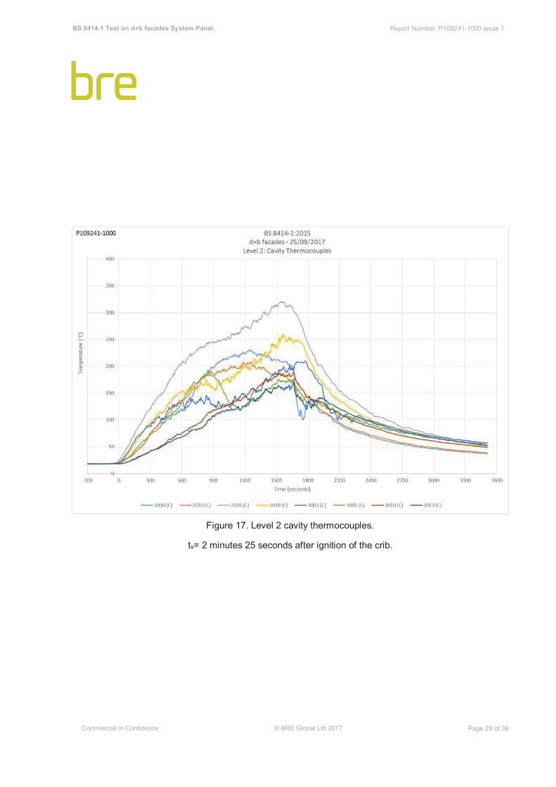
Parameter Result Ts, Start Temperature 17°C ts, Start time 2 minutes 25 seconds after ignition of crib. Peak temperature / time at Level 2, External 487°C (22 minutes 45 seconds after ts) Peak temperature / time at Level 2, Cavity 321°C (25 minutes 45 seconds after ts) Peak temperature / time at Level 2, Insulation 30°C (41 minutes 55 seconds after ts)

BS 8414-1 Test on d+b facades System Panel. Report Number: P109241-1000 Issue 1
Commercial in Confidence © BRE Global Ltd 2017 Page 9 of 36
5.3 Visual observations Table 2. Visual Observations – Refer to Figure 2 for system schematic. Time*
(mins:secs) ts
(mins:secs) Description 00:00 Ignition of crib. 00:45 The flame tips reach the top of the crib. 02:00 The flames from the combustion chamber are impinging on the cladding system. 02:25 00:00 Start time (ts) criteria achieved: External temperature 2.5m above the top of the combustion chamber in excess of 217°C (=200°C+Ts). 02:30 00:05 Flame tips to top of panel 1B&1C. 03:20 00:55 Flame tips to mid height of panels 2B&2C. 03:45 01:20 Flame tending towards wing wall panel 1A. 04:00 01:35 Smoke clearing. 04:40 02:15 Flame tips to top of panels 2B&2C. 06:10 03:45 Panel coating removed up to mid-height of panels 1B&1C to expose aluminium. 06:45 04:20 Smoke emission from top of system. 07:00 04:35 Sporadic flaming to top of panels 3B&3C. 07:15 04:50 Consistent flaming to top of panels 2B&2C. 09:00 06:35 Panel coating removed to top of panels 1B&1C to expose aluminium. 09:15 06:50 Flames at the base of panels 2B&2C. 09:45 07:20 Flaming along ¾-width of horizontal joint at the base of panels 2B&2C. 10:30 08:05 Consumption of bottom of panel 1B. 11:00 08:35 Consumption of bottom of panels: 1B (1m by 0.6m), 0B (0.5 by 0.3m), 0C (0.3m x 0.3m).

BS 8414-1 Test on d+b facades System Panel. Report Number: P109241-1000 Issue 1
Commercial in Confidence © BRE Global Ltd 2017 Page 10 of 36
Time* (mins:secs)
ts
(mins:secs) Description 12:40 10:15 Panel coating removed up to mid-height of panel 2B. 14:20 11:55 Consumption of panels: 1B (full-height x 0.7m wide), 1C (full-height by 0.3m), 0B (70% height by 0.7m wide), 0C (70% height by 0.7m wide). 14:30 12:05 Detachment from system. 16:20 13:55 Flaming on wing wall to top of panel 1A. 17:15 14:50 Flaming along panel 1A-2A horizontal junction. 17:40 15:15 Flaming to edge of wing wall at panel 1A-2A horizontal junction. 18:45 16:20 Sustained surface flaming on wing wall. 19:00 16:35 Consumption of bottom of panels 2B&2C. Consumption of central rail where exposed. 21:00 18:35 Wing wall surface flaming ceased. 21:41 19:16 Panel coating removed up to top of panels 2B/2C. Distortion and consumption at base of panels 3B&3C. 23:30 21:05 Detachment of cavity barrier along top edge of combustion chamber opening. 24:30 22:05 Wing wall flaming has ceased. Over 80% consumption of panels 0B&1B. Over 20% consumption of panel 1C. Over 50% consumption of panel 0C. 28:00 25:35 No significant visual change since the last observation. Consumption to bottom of panels 2B&2C. 30:00 27:35 Crib extinguished. 60:00 57:35 Test terminated. *Time from point of ignition.
BS 8414-1 Test on d+b facades System Panel. Report Number: P109241-1000 Issue 1
Commercial in Confidence © BRE Global Ltd 2017 Page 11 of 36
6 Post-Test Damage Report
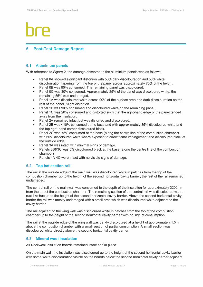
6.1 Aluminium panels With reference to Figure 2, the damage observed to the aluminium panels was as follows: • Panel 0A showed significant distortion with 50% dark discolouration and 50% white discolouration tapering from the top of the panel across approximately 75% of the height. • Panel 0B was 90% consumed. The remaining panel was discoloured. • Panel 0C was 30% consumed. Approximately 25% of the panel was discoloured white, the remaining 55% was undamaged. • Panel 1A was discoloured white across 90% of the surface area and dark discolouration on the rest of the panel. Slight distortion. • Panel 1B was 90% consumed and discoloured white on the remaining panel. • Panel 1C was 20% consumed and distorted such that the right-hand edge of the panel tended away from the insulation. • Panel 2A remained intact but was distorted and discoloured. • Panel 2B was <10% consumed at the base and with approximately 85% discoloured white and the top right-hand corner discoloured black. • Panel 2C was <5% consumed at the base (along the centre line of the combustion chamber) with 60% discoloured white where exposed to direct flame impingement and discoloured black at the outside edge. • Panel 3A was intact with minimal signs of damage. • Panels 3B&3C was 5% discoloured black at the base (along the centre line of the combustion chamber) • Panels 4A-4C were intact with no visible signs of damage.
6.2 Top hat section rail The rail at the outside edge of the main wall was discoloured white in patches from the top of the combustion chamber up to the height of the second horizontal cavity barrier, the rest of the rail remained undamaged. The central rail on the main wall was consumed to the depth of the insulation for approximately 3200mm from the top of the combustion chamber. The remaining section of the central rail was discoloured with a rust-like hue up to the height of the second horizontal cavity barrier. Above the second horizontal cavity barrier the rail was mostly undamaged with a small area which was discoloured white adjacent to the cavity barrier. The rail adjacent to the wing wall was discoloured white in patches from the top of the combustion chamber up to the height of the second horizontal cavity barrier with no sign of consumption. The rail at the outside edge of the wing wall was darkly discoloured at a height of approximately 1.5m above the combustion chamber with a small section of partial consumption. A small section was discoloured white directly above the second horizontal cavity barrier. 6.3 Mineral wool insulation All Rockwool insulation boards remained intact and in place. On the main wall, the insulation was discoloured up to the height of the second horizontal cavity barrier with some white discolouration visible on the boards below the second horizontal cavity barrier adjacent

BS 8414-1 Test on d+b facades System Panel. Report Number: P109241-1000 Issue 1
Commercial in Confidence © BRE Global Ltd 2017 Page 12 of 36
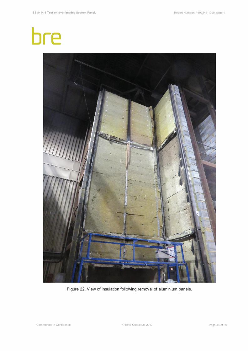
to the vertical cavity barrier. Above the second horizontal cavity barrier some insulation to the right of the central rail was discoloured brown– see Figure 23. All plastic insulation fixings were consumed below the height of the second horizontal cavity barrier (approximately 4000mm above the combustion chamber opening). On the wing wall, the insulation boards below the first horizontal cavity barrier were discoloured. There were three localised areas that were darkly discoloured, each tapering up approximately 200mm at the outside edge of the wing wall, from the combustion of the polypropylene insulation anchors. Above the first horizontal cavity barriers the Rockwool insulation boards were similarly discoloured with six dark areas of localised discolouration at approximately 1500-3000mm above the combustion chamber – see Figure 24. All plastic insulation fixings were consumed below an approximate height of 3200mm above the combustion chamber opening). Above the second horizontal cavity barrier, the Rockwool insulation boards on the wing wall sustained minimal visible damage. 6.4 Horizontal (compression) cavity barriers Approximately 25% of the first row horizontal cavity barrier had detached from the main wall. There was aluminium deposited on the cavity barrier from the top hat section rail. On the wing wall a small amount of detachment was observed at the outside edge of the wall – see Figure 22. The second row horizontal cavity barrier was severely damaged. On the main wall, along the centre line of the combustion chamber, there was significant detachment and localised areas of dark discolouration. The significant section of horizontal cavity barrier on the wing wall also detached and was darkly discoloured – see Figure 23. 6.5 Vertical (compression) cavity barrier Below the first horizontal cavity barrier the vertical cavity barrier was mostly intact with some discolouration. A substantial proportion of the vertical cavity barrier had detached from an approximately 300mm-long section directly above the height of the first horizontal cavity barrier. Another, approximately 500mm-long section, had detached, 400mm below the height of the second horizontal cavity barrier with additional, small areas of detachment in between. Directly above the second horizontal cavity barrier the vertical cavity barrier was discoloured for approximately 300mm and slightly distorted at the top and base creating a curved profile. 7 Conclusion BS8414 Part 1:2015 + A1:2017 [1] does not contain acceptance criteria and therefore this test report does not indicate a pass or fail of the product.

BS 8414-1 Test on d+b facades System Panel. Report Number: P109241-1000 Issue 1
Commercial in Confidence © BRE Global Ltd 2017 Page 13 of 36
8 Reference 1. BS 8414-1:2015 + A1:2017, ’Fire performance of external cladding systems – Part 1: Test method for non-load bearing external cladding systems applied to the masonry face of the building’, British Standards Institution, London, 2015.

BS 8414-1 Test on d+b facades System Panel. Report Number: P109241-1000 Issue 1
Commercial in Confidence © BRE Global Ltd 2017 Page 14 of 36
9 Figures
9.1 Diagrams of finished face of the cladding system Figure 2. Layout of panels and numbering system used for reporting. Not to scale.

BS 8414-1 Test on d+b facades System Panel. Report Number: P109241-1000 Issue 1
Commercial in Confidence © BRE Global Ltd 2017 Page 15 of 36 Figure 3. TC positions and panel numbering (0A – 4C). Not to scale.

BS 8414-1 Test on d+b facades System Panel. Report Number: P109241-1000 Issue 1
Commercial in Confidence © BRE Global Ltd 2017 Page 16 of 36
9.2 Installation photographs
Figure 4. ‘U’ bracket fixed to wall.

BS 8414-1 Test on d+b facades System Panel. Report Number: P109241-1000 Issue 1
Commercial in Confidence © BRE Global Ltd 2017 Page 17 of 36 Figure 5. Vertical rails fixed to ‘U’ brackets.

BS 8414-1 Test on d+b facades System Panel. Report Number: P109241-1000 Issue 1
Commercial in Confidence © BRE Global Ltd 2017 Page 18 of 36 Figure 6. Close up view of vertical rail and 'U' bracket.

BS 8414-1 Test on d+b facades System Panel. Report Number: P109241-1000 Issue 1
Commercial in Confidence © BRE Global Ltd 2017 Page 19 of 36 Figure 7. View of Rockwool insulation and cavity barriers installed.

BS 8414-1 Test on d+b facades System Panel. Report Number: P109241-1000 Issue 1
Commercial in Confidence © BRE Global Ltd 2017 Page 20 of 36 Figure 8. Completed installation prior to test.
BS 8414-1 Test on d+b facades System Panel. Report Number: P109241-1000 Issue 1
Commercial in Confidence © BRE Global Ltd 2017 Page 21 of 36
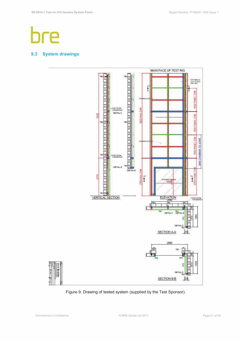
9.3 System drawings Figure 9. Drawing of tested system (supplied by the Test Sponsor).

BS 8414-1 Test on d+b facades System Panel. Report Number: P109241-1000 Issue 1
Commercial in Confidence © BRE Global Ltd 2017 Page 27 of 36
9.4 Temperature data Figure 15. Level 1 external thermocouples. ts= 2 minutes 25 seconds after ignition of the crib.

BS 8414-1 Test on d+b facades System Panel. Report Number: P109241-1000 Issue 1
Commercial in Confidence © BRE Global Ltd 2017 Page 28 of 36
Figure 16. Level 2 external thermocouples. ts= 2 minutes 25 seconds after ignition of the crib.
BS 8414-1 Test on d+b facades System Panel. Report Number: P109241-1000 Issue 1
Commercial in Confidence © BRE Global Ltd 2017 Page 29 of 36
Figure 17. Level 2 cavity thermocouples. ts= 2 minutes 25 seconds after ignition of the crib.

BS 8414-1 Test on d+b facades System Panel. Report Number: P109241-1000 Issue 1
Commercial in Confidence © BRE Global Ltd 2017 Page 30 of 36
Figure 18. Level 2 insulation thermocouples. ts= 2 minutes 25 seconds after ignition of the crib.

BS 8414-1 Test on d+b facades System Panel. Report Number: P109241-1000 Issue 1
Commercial in Confidence © BRE Global Ltd 2017 Page 31 of 36
9.5 Post-test photographs
Figure 19. Full height photograph of the cladding system post-test.

BS 8414-1 Test on d+b facades System Panel. Report Number: P109241-1000 Issue 1
Commercial in Confidence © BRE Global Ltd 2017 Page 32 of 36 Figure 20. View of main wall panels above the combustion chamber.

BS 8414-1 Test on d+b facades System Panel. Report Number: P109241-1000 Issue 1
Commercial in Confidence © BRE Global Ltd 2017 Page 33 of 36 Figure 21. View of wing wall panels above the combustion chamber.
BS 8414-1 Test on d+b facades System Panel. Report Number: P109241-1000 Issue 1
Commercial in Confidence © BRE Global Ltd 2017 Page 34 of 36 Figure 22. View of insulation following removal of aluminium panels.

BS 8414-1 Test on d+b facades System Panel. Report Number: P109241-1000 Issue 1
Commercial in Confidence © BRE Global Ltd 2017 Page 35 of 36
Figure 23. Damage to insulation above the second row of horizontal cavity barrier.

BS 8414-1 Test on d+b facades System Panel. Report Number: P109241-1000 Issue 1
Commercial in Confidence © BRE Global Ltd 2017 Report Ends Page 36 of 36 Figure 24. Main-wing wall junction below the second horizontal cavity barrier.