bre - eurocode 7, a commentary
TRANSCRIPT


Eurocode 7a commentary
Brian SimpsonArup Geotechnics
Richard DriscollBRE
BREGarston Watford WD2 7JR

Prices for all availableBRE publications canbe obtained from: Construction ResearchCommunications Ltd151 Rosebery AvenueLondon, EC1R 4QX Tel 0171 505 6622Fax 0171 505 [email protected]
BR 344ISBN 1 86081 226 0
© Copyright BRE 1998First published 1998
Published by Construction ResearchCommunications Ltd bypermission of Building ResearchEstablishment Ltd. Applications to copy allor any part of thispublication should bemade to: Construction ResearchCommunications Ltd,PO Box 202, Watford,Herts, WD2 7QG
Cover: bridge piers ofthe Øresund Link,SwedenClient:ØresundkonsortietConcept design: ASO GroupDetailed design and build:Sundlink

SUMMARY OF CONTENTS
Page
FOREWORD iv
PART A FUNDAMENTALS 1
PART B IMPORTANT FEATURES OF EUROCODE 7 PART 1 15
PART C CLAUSE-BY-CLAUSE COMMENTARY 41
PART D THE WAY AHEAD 107
PART E WORKED EXAMPLES 123
REFERENCES 177
iii

FOREWORD
This Commentary consists of guidance and recommendations related to draftEurocode 7 Part 1 – DD ENV 1997-1:1995. Its contents are necessarily of ageneral nature, and responsibility for the application of the commentary, inparticular engineering projects, remains with the user.
AuthorsBrian Simpson, Arup GeotechnicsRichard Driscoll, BRE
Steering GroupS Desai, Department of the Environment, Transport and the RegionsD I Bush, The Highways AgencyP R J Morrison, Arup GeotechnicsC A Raison, Keller Ground EngineeringH D St John, Geotechnical Consulting GroupR P Thompson, Edge Consultants U.K. Ltd
ACKNOWLEDGEMENTS
‘Eurocode 7: a commentary’ has been prepared under Contract No 39/10/11from the Department of the Environment, Transport and the Regions. Theassistance of Dr S Desai is gratefully acknowledged. Dr Paul Morrison isthanked for his contributions to the worked examples and other parts of thecommentary.
iv EUROCODE 7: A COMMENTARY

Eurocode 7: a commentary
Part A Fundamentals
11

CONTENTS
A1 INTRODUCTION 3A1.1 Purpose of this commentary 3A1.2 Basis of this commentary 3A1.3 Background of development of the Eurocodes 3A1.4 Historical note on the development of Eurocode 7 4A1.5 National Application Documents 5A1.6 Current status of EC7 and the British NAD 5
A2 HOW TO USE EUROCODE 7 6A2.1 Who should use it 6A2.2 The system of Eurocode documents 6A2.3 Overview of Eurocode 7 Part 1 6A2.4 The United Kingdom National Application Document for
Eurocode 7 Part 1 7A2.5 Eurocode 7, Parts 2 and 3 7A2.6 Other CEN and ISO documents 8A2.7 Relationship to British Standards 8A2.8 Some terminology 9
A3 HOW TO USE THIS COMMENTARY 10A3.1 The five parts of the commentary 10A3.2 Abbreviations adopted 10A3.3 Requirements, recommendations and some administrative
definitions 11
2 EUROCODE 7: A COMMENTARY

A1 INTRODUCTION
A1.1 Purpose of this commentaryThis commentary is intended to help the reader to understand Eurocode 7, inthe form published in 1995, by providing:a reviews of new concepts;b clarification of the text;c comparisons against existing British practice;d worked examples.
It does not attempt to replace text books on geotechnical engineering, but islimited to the task of explaining the intentions of Eurocode 7, especiallywhere these differ from previous design approaches. The commentary doesnot debate alternatives to Eurocode 7; possible future changes to theEurocode are discussed in Part D.
A1.2 Basis of this commentaryThe basis of this commentary is Eurocode 7: Geotechnical Design – Part 1:General rules, published in 1995. The serial number of this document in thesystem of the Comité Européen de Normalisation is ENV 1997-1. (Note thatin this reference ‘1997’ is a reference number, not a year.) In this commentaryit will generally be referred to as ‘EC7-1’, or, where it is obvious that Part 1 isreferred to, simply as ‘EC7’. In Britain, the British Standards Institutionpublished DD ENV 1997-1:1995, containing EC7-1 together with its UnitedKingdom National Application Document (see A1.5 and A1.6).
The commentary is in five Parts, A to E, as explained in A3.1, and referencesto the commentary are in the form ‘A1.2’, ‘C8.2.3’, etc. References toEurocodes are in the form ‘EC7, 1.2.3’, ‘EC3-5, 5.3.4’, etc. The latter of thesereferences means ‘Eurocode 3, Part 5, subclause 5.3.4’.
A1.3 Background of development of the EurocodesThe objectives of the Eurocodes are set out in a foreword which is common toall of them. It appears as follows in ENV1997-1:1995, though in more recentEurocodes item (2) has been omitted.1 The structural Eurocodes comprise a group of standards for the structural
and geotechnical design of buildings and civil engineering works.2 They are intended to serve as reference documents for the following
purposes:(a)As a means to prove compliance of building and civil engineering works with the essential requirements of the Construction ProductsDirective (CPD).(b)As a framework for drawing up harmonised technical specifications forconstruction products.
3 They cover execution and control only to the extent that is necessary toindicate the quality of the construction products, and the standard of theworkmanship, needed to comply with the assumptions of the design rules.
4 Until the necessary set of harmonised technical specifications for productsand for methods of testing their performance is available, some of theStructural Eurocodes cover some of these aspects in informative annexes.
In summary, the Eurocodes were originally intended as checking documentsfor design, proving compliance with the European regulations; the omissionof Objective 2 makes this less clear. In their preparation there has been strongemphasis on the need to ensure fair competition in the construction industryand to harmonise requirements between countries. Their purpose is to giverules which will lead to acceptable assemblies of products. They are notintended to advise or educate; these tasks are left to text books. As item 3above suggests, they contain relatively little about construction, which is leftto other CEN standards. CEN committee TC288 has been responsible for the
PART A FUNDAMENTALS 3

development of geotechnical construction standards (see Table A3.2 at theend of this Part).
The Eurocodes were initiated by the Commission of the EuropeanCommunities (CEC) as a development of the Construction ProductsDirective (CEC Council Directive 89/106/EEC dated 21 December 1988,together with Interpretative Documents published 16 July 1993). TheConstruction Products Directive requires a series of harmonised EuropeanStandards which provide certain ‘Essential Requirements’ of safety, economyand fitness for use, but which do not, by their [national] disparity, hinder tradewithin the Community. The task of producing these Standards was delegated tothe Comité Européen de Normalisation (CEN), of which national standardsbodies such as BSI are members.
Initially, the Eurocodes were directed almost exclusively at buildingstructures. However, their scope has gradually increased and now includescivil engineering structures such as bridges, with developments underway fortowers, silos etc. Their main geotechnical application to date has been tobridge structures in Denmark (Braestrup (1996)) and France. In thegeotechnical field, any of these structures may require a wide range ofgeotechnical design.
At the present stage of development (early 1998), nine Eurocodes havebeen nominated:EN 1991 Eurocode 1 Basis of design and actions on structuresEN 1992 Eurocode 2 Design of concrete structuresEN 1993 Eurocode 3 Design of steel structuresEN 1994 Eurocode 4 Design of composite steel and concrete structuresEN 1995 Eurocode 5 Design of timber structuresEN 1996 Eurocode 6 Design of masonry structuresEN 1997 Eurocode 7 Geotechnical designEN 1998 Eurocode 8 Design of structures for earthquake resistance.EN 1999 Eurocode 9 Design of aluminium alloy structures
It is likely that Eurocode 1 will be divided into two documents: Basis ofdesign separated from Actions on structures. The relationship of theseEurocodes to corresponding British codes is shown in Table A3.1 at the end ofthis Part.
A1.4 Historical note on the development of Eurocode 7In 1976 the European Commission agreed to sponsor development of a set ofEuropean codes of practice for building structures. The purpose of these wasto encourage free trade between member states. In 1980, an agreement wasreached between the Commission of the European Communities (CEC) andthe International Society for Soil Mechanics and Foundation Engineering(ISSMFE), according to which the Society should undertake to surveyexisting codes of practice for foundations within the member states and todraft a model code which could be adopted as Eurocode 7. In 1981, theISSMFE established an ad hoc committee for this task. Following manyconsultations and international meetings, this committee produced in 1987 a‘draft model for Eurocode 7’. The CEC sponsored further work on this draftcode for three years to 1990, after which the work was transferred for furtherdevelopment, issue and maintenance to CEN, with agreement that the EFTAsecretariat would also support the work. CEN/TC250 was therefore set up,and this committee has overseen the development of Eurocodes since 1990. A sub-committee is responsible for each Eurocode, that for Eurocode 7 beingCEN/TC250/SC7.
During the whole of this process, the development has been led and themain committees have been chaired by Dr Niels Krebs Ovesen of Denmark.The chairmanship of CEN/TC250/SC7 will pass to Dr Roger Frank, ofFrance, in May 1998.
4 EUROCODE 7: A COMMENTARY

A1.5 National Application DocumentsIn the approach adopted to date, each nation is to publish a NationalApplication Document (NAD) for each Eurocode. Numerical values of safetyfactors and some other quantities are given in the Eurocodes as ‘boxed values’,generally in square brackets [ ]. The boxed values are intended to beindicative, and each nation is to specify the values to be used for constructionon its own territory (irrespective of the nationality or location of the designer).These are provided in the National Application Documents.
Some of the available NADs for EC7 have been quite extensive, and haveadded to or amended the rules of the Eurocode.
National Application Documents are written in the languages of theircountries of origin, though most are being translated into English, at leastinformally. They may refer to other national codes which are not available inEnglish. British engineers may reflect, however, on the great advantage they gain from the fact that English is the most common language inEuropean usage.
The possible future status of NADs is discussed in D2.4.
A1.6 Current status of EC7 and the British NADEurocode 7 Part 1 was published as an ‘ENV’ (a European pre-standard) byCEN in October 1994 and by BSI in 1995 as DD ENV 1997-1:1995. Two yearslater, in 1997, Eurocode 7 Part 1 was subjected to voting and accepted in July1997 for further development to become an EN (European standard, orEuronorm). Since this process will take several years, the 1995 publicationforms the basis of this commentary.
Also in 1997, ENV (pre-standard) versions of Parts 2 and 3 of Eurocode 7were accepted for publication. These will probably be available in 1998,publication being withheld until translation into French and German iscomplete. Part 2 is a standard for ‘Design based on laboratory testing’ and Part 3 ‘Design based on field testing’. These are considered further in A2.5.
British Standard DD ENV 1997-1:1995 also contains the United KingdomNAD. This is partly an ‘NAD for the draft (ENV) EC7’, but also principally a‘draft NAD for the final EC7 (EN)’. It is relatively short, though it containssome material in addition to the boxed values.
PART A FUNDAMENTALS 5
A2 HOW TO USE EUROCODE 7
A2.1 Who should use itEurocodes are intended to be used by engineers in general building and civilengineering design. They are particularly relevant on projects involvinginternational cooperation or competition, especially on publicly funded work,where it may become a legal requirement to accept designs which satisfy theEurocodes. They have also been found useful in some situations where thesafety systems of existing national codes are difficult to apply.
Eurocodes are written for use by qualified and experienced personnel. Theprecise terms of these qualifications are not defined, except that they must beappropriate and adequate for the project in hand. In almost all cases, thisdemands that designs to EC7 are supervised by a qualified civil engineer withrelevant geotechnical training and experience. It is also a basic assumptionthat all construction activities are carried out in accordance with relevantstandards (EC7, 1.4).
It is not the main purpose of Eurocodes to provide assistance orinformation to designers, and they are not teaching manuals. Henceinexperienced designers will not be able to proceed adequately on the basis ofthe Eurocodes alone. This is particularly true for EC7.
The Eurocodes are intended to provide a check on the safety of proposedstructures, so they will be used by both designers and checkers.
A2.2 The system of Eurocode documentsThe current list of Eurocodes was provided in A1.3 above. Eurocode 1, Basisof design and actions on structures, sets out the basic approach to be adoptedto design, especially calculations, and provides definitions for terminology inthe limit state system. Some of this material is repeated in other Eurocodes,particularly EC2 and EC3, but it is intended that this repetition will beremoved in the future. EC7 generally avoids repeating material from EC1, soit is necessary that the user of EC7 also has EC1 available and is familiar withit. It is possible that in the future ‘Basis of design’ will become ‘EC0’ – EN1990.
The Eurocodes aim to be an inter-dependent and consistent set, withoutrepetition of material. Thus, to design a steel pile, EC7 will be used with EC3,or for a concrete retaining wall, EC7 will be used with EC2. The systems offactors of safety have been selected to make this possible. Design for seismicsituations receives very little attention in Eurocodes 2 to 7 as these rely onEC8 for this purpose. EC8, however, refers back to other Eurocodes.
All the Eurocodes contain two levels of text: Principles and ApplicationRules. Principles are mandatory requirements of defi nitions. Application Rulesare ways in which the design may be shown to comply with the Principles;they are not mandatory. This distinction is discussed further in C1.3.
It will be clear from A1.5 above that no current Eurocode is complete initself, but must be supplemented by the NAD of the country in whichconstruction is to take place. In Britain, EC7 and the UK NAD are publishedtogether by BSI, as noted in A1.6.
A2.3 Overview of Eurocode 7 Part 1EC7-1 provides, in outline, all the requirements for design of geotechnicalstructures. It provides little assistance or information, which the designer musttherefore seek in other texts. It relies upon other Eurocodes and CENdocuments, as outlined in this section of the commentary.
The sections of EC7-1 may be grouped as follows:
Overall approach1 General2 Basis of geotechnical design
6 EUROCODE 7: A COMMENTARY

Ground investigation3 Geotechnical data
Design aspects of construction activities4 Supervision of construction, monitoring and maintenance
Design of specifi c elements5 Fill, dewatering, ground improvement6 Spread foundations7 Pile foundations8 Retaining structures9 Embankments and slopes
All users should be familiar with Sections 1 to 4. In particular, Section 2provides the basic approach to limit state design and to calculations, includingthe values of most of the partial factors of safety (but see A2.4 on the UKNAD); further factors are provided for design of piles and anchors in Sections7 and 8. Users will generally then proceed to one of the sections 5 to 9 asrequired, though it should be noted that overall site stability is covered inSection 9, which is relevant to all the items considered in Sections 5 to 8.
Generally, the code provides specific rules for ultimate limit staterequirements but leaves the criteria for serviceability limit states to be decidedby designers and their clients. It outlines the basic requirements of calculationmethods but in most cases does not give detailed formulae. The rules of CENprohibit the inclusion of worked examples of calculations.
A discussion of the geotechnical design procedure based on EC7-1 ispresented in B1.
A2.4 The United Kingdom National Application Document for Eurocode 7Part 1
For design of projects to be constructed in the United Kingdom, the user ofEC7-1 must use the UK NAD for EC7-1, contained in the BSI publication DDENV 1997-1:1995. This provides the ‘British’ values of partial factors of safetyand some other constants, which over-ride the ‘boxed values’ given in EC7-1itself. In the 1995 publication, the British values are identical to the boxedvalues, but it would be unsafe to assume that this will remain the case in future,so it is wise to develop the habit of referring to the NAD for factor values, ifthe construction will be in the UK. Equally, for construction in anotherEuropean country, the NAD of that country must be used, so the habit ofusing the NAD rather than EC7-1 itself will still be helpful.
The UK NAD also contains a short annex giving clarification of some of themore difficult clauses of EC7-1 and provides cross-references to relevantBritish codes. In particular, where EC7-1 has used phases like ‘internationallyrecognised standards’ or ‘standardised procedures’, the NAD requires, in itsAnnex A, that British Standards are used. (Note: In the 1995 publication of theNAD, the words ‘Normative’ and ‘Informative’ have been interchanged, inerror, in the headings of Annexes A and B and in the list of references at theend of the NAD.)
A2.5 Eurocode 7, Parts 2 and 3In general, Eurocodes do not consider testing of materials. EC1 Part 1 has asection on ‘Design assisted by testing’, but this is concerned mainly withtesting of prototype structural elements. Nevertheless, the mandate fordrafting Eurocode 7 required that it should include soil testing, and this led tothe development of Parts 2 and 3, respectively ‘Geotechnical design assistedby laboratory testing’ and ‘Geotechnical design assisted by field testing’.These documents were approved for publication as pre-standards (ENVs) in1997. They are outside the scope of this commentary, but their future role isbriefly described here.
PART A FUNDAMENTALS 7

In scope, Parts 2 and 3 of EC7 lie somewhere between BS 5930 on siteinvestigation and BS 1377 on soil testing; they also provide rather moreinformation on interpretation of test results. Part 3 provides guidance on thescope of site investigation required for common structures and Part 2discusses the suites of tests which could be included. They are principally ofuse to engineers who have to specify and interpret testing, rather than totechnicians responsible for carrying out the tests.
Both Parts lead to the calculation of ‘derived values’ for parameters, basedeither on direct calculation or on calibrations. For example, a method ofderiving angle of shearing resistance from SPT results is given in Part 3. Each‘derived value’ is based on a single test result; the set of derived values,possibly from more than one type of test, may be used in the assessment ofcharacteristic values of the parameters to be used in design calculations. Thusderived values are not the same as characteristic values, which are discussedfurther in B4.
In their pre-standard (ENV) form, Parts 2 and 3 also contain somecalculation methods based on the parameters considered. It is likely that these will either be moved into Part 1 or eliminated in the EN versions ofthese two parts.
A2.6 Other CEN and ISO documentsLists of CEN and ISO standards relevant to geotechnical design andconstruction are presented in Tables A3.2 and A3.3, which also listcorresponding or related British Standards.
Within the European system being developed by CEN, the Eurocodes areto be used together with codes on production of civil engineering productsand on geotechnical construction practice. These are produced by variousCEN technical committees, CEN/TC288 being responsible for the standardson geotechnical construction.
EC7, in the form ENV 1997-1:1995 was published before the current draftsof the TC288 documents and so does not refer to them. The TC288 standardsrefer to EC7, and also make some additions to its design requirements, mostnotably in relation to design of ground anchors in prEN 1537. However, it isintended that they will not contain design requirements when the system iscomplete, with all of them being adequately covered by EC7.
A2.7 Relationship to British StandardsUnder the rules of CEN, codes published by national standards institutionsthat conflict with the principles of the Eurocode must normally be withdrawnwhen a CEN standard is produced at EN status. However, an exception hasbeen made for Eurocodes, allowing a period of ‘coexistence’ of nationalstandards with the EN for some years after publication of the EN.
For EC7 a particular problem arises in deciding which British Standards arein conflict with the EN. For example, BS 8002 contains material on the designof retaining walls which is not included in EC7. The same applies to othercodes such as BS 8004, BS 8006, BS 5930, etc. The British codes provide muchadvisory information, which is ‘informative’ rather than obligatory, so they aresomewhat different in nature from the Eurocodes; it might therefore bequestioned whether they conflict with the Eurocode.
A possible way ahead for the user could be to design to the rules of EC7 butto use the British codes as supplementary advice. This approach isrecommended by this commentary, though it would become difficult in asituation where the British code clearly demands a more conservativeapproach than does EC7. How would a court of law view a design whichcomplied with the Eurocode but not with an equally current British code?
A possible solution to this dilemma might be for BSI to continuepublication of the British codes, adding a rider that, in case of conflict, theEurocode governs.
8 EUROCODE 7: A COMMENTARY

The situation is different for the relationship between EC7 Parts 2 and 3and BS 1377 – Methods of test for soils for civil engineering purposes. BS 1377provides precise descriptions of the apparatus and procedures required bytests, together with methods of calculating the results of individual tests. Theuse and interpretation of the tests are not within its scope, however. As notedin A2.5, EC7 Parts 2 and 3 consider mainly the planning, interpretation anduse of suites of tests, but have relatively little detail on the test methods. Hereagain, the two codes are not in conflict.
A2.8 Some terminologyThe Eurocodes introduce some terms which are not familiar in Britain. Insome cases, English words are defined to have meanings which may beunexpected. Some of these terms are noted here, with references to otherpoints in this commentary or the Eurocodes where more definitive definitionswill be found. A fairly comprehensive list of terminology is given in EC1, 1.5,and this is supplemented by EC7, 1.5. See also C1.5.
ActionGenerally equivalent to ‘load’. EC1, 1.5.3.1 says that an action is an appliedforce or an imposed displacement. EC7, 2.4.2(1)P notes that For any calculationthe values of actions are known quantities. Actions are not unknowns in thecalculation model. See also C2.4.2.
Characteristic valuesSee B4.
Design valuesSee B2.4.
ExecutionThe construction of a project on site. See EC1, 1.5.1.10 and 1.5.1.1-5.
Limit statesSee B2.1.
Principles and Application RulesSee EC1, 1.4 and EC7, 1.3. Principles are mandatory paragraphs; theirnumbers are followed by the letter P.
PART A FUNDAMENTALS 9

A3 HOW TO USE THIS COMMENTARY
A3.1 The five parts of the commentaryThis commentary is divided into five sections which are intended to be usedin different ways.
Part A – FundamentalsThe user should read through Part A to obtain a general backgroundunderstanding to the use of Eurocode 7.
Part B – Important features of Eurocode 7 Part 1Part B consists of a series of essays on concepts in EC7-1 which require clearunderstanding if the code is to be used effectively. Some of these concepts arerelatively new and have been controversial during the development of EC7.They have been developed, however, because they are believed to offer theclearest way available to communicate the essence of good, systematiseddesign practice.
The reader is advised to study Part B and to understand its concepts as wellas possible.
Part C – Clause-by-clause commentaryPart C is drafted on the assumption that it will be read alongside EC7-1. Itdoes not repeat the text of EC7-1, but is intended to provide clarification of itsmeaning, pointers to related clauses and guidance to other publications whichassist the use of the clauses.
Part C should be used for reference whilst working with EC7-1.Numbering refers specifically to the EC7 clause, subclause etc which is
being discussed. Each numbered heading is prefaced by a ‘C’ to distinguish,for example, commentary on Clause 1.1 (C1.1) from Clause 1.1 itself (EC7, 1.1).
Part D – The way aheadPart D considers the use of EC7-1 outside the United Kingdom, and alsodiscusses future development and research needs.
Part E – Worked examplesPart E supplements earlier parts by providing extended examples of theapplication of EC7-1 to engineering design problems.
A list of errata for EC7-1 is provided as Appendix 2 in Part C.
A3.2 Abbreviations adoptedThe following abbreviations are used in this commentary.BSI British Standards InstitutionCEN Comité Européen de NormalisationECn Eurocode nEC7-1 Eurocode 7 Part 1, as contained in the DD ENV 1997-1:1995EN Euronorm, European standardENV published European pre-standard (Vornorm in German)NAD National Application Document. The United Kingdom NAD is
contained in BSI publication DD ENV 1997-1:1995prEN Pre-norm – draft document circulated for comment but not
generally published (similarly prENV)SLS serviceability limit stateULS ultimate limit state
10 EUROCODE 7: A COMMENTARY

A3.3 Requirements, recommendations and some administrativedefinitions
The Eurocodes use the verbs ‘shall’ and ‘should’ in a carefully defined manner.As noted in C1.3, ‘shall’ is used in Principles and ‘should’ in Application Rules.
In this commentary, the verb ‘must’ is used to mean that, in the opinion ofthe authors of the commentary, EC7-1 is imposing a mandatory requirement.
The word ‘recommended’ is used to indicate the recommendations of theauthors of this commentary.
In C1.5.2, definitions are suggested for the words ‘considered’, ‘assess’ and‘evaluate’, which are used repeatedly in EC7-1.
The following hierarchy of numbering is taken from ‘Harmonised editorialstyle for Eurocodes’ issued by CEN/TC250 in January 1996:Section 3Clause 3.1Subclause 3.1.1Paragraph 3.1.1(4)
In this commentary, these nouns have been omitted where the context allows.References to EC7-1 are in the form ‘EC7, 1.2.3’. References to otherEurocodes appear as ‘EC3-5, 5.3.4’, etc., and references to the commentaryare in the form ‘A1.2’, ‘C8.2.3’, etc.
PART A FUNDAMENTALS 11
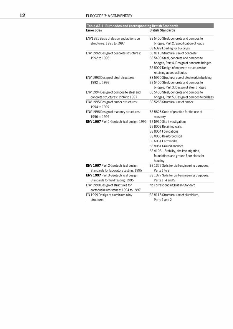
Table A3.1 Eurocodes and corresponding British StandardsEurocodes British Standards
ENV1991 Basis of design and actions on BS 5400 Steel, concrete and composite structures: 1995 to 1997 bridges, Part 2, Specification of loads
BS 6399 Loading for buildingsENV 1992 Design of concrete structures: BS 8110 Structural use of concrete
1992 to 1996 BS 5400 Steel, concrete and composite bridges, Part 4, Design of concrete bridges
BS 8007 Design of concrete structures for retaining aqueous liquids
ENV 1993 Design of steel structures: BS 5950 Structural use of steelwork in building1992 to 1998 BS 5400 Steel, concrete and composite
bridges, Part 3, Design of steel bridgesENV 1994 Design of composite steel and BS 5400 Steel, concrete and composite
concrete structures: 1994 to 1997 bridges, Part 5, Design of composite bridgesENV 1995 Design of timber structures: BS 5268 Structural use of timber
1994 to 1997ENV 1996 Design of masonry structures: BS 5628 Code of practice for the use of
1996 to 1997 masonryENV 1997 Part 1 Geotechnical design: 1995 BS 5930 Site investigations
BS 8002 Retaining wallsBS 8004 FoundationsBS 8006 Reinforced soilBS 6031 Earthworks BS 8081 Ground anchorsBS 8103-1 Stability, site investigation,
foundations and ground floor slabs for housing
ENV 1997 Part 2 Geotechnical design BS 1377 Soils for civil engineering purposes, Standards for laboratory testing: 1995 Parts 1 to 8
ENV 1997 Part 3 Geotechnical design BS 1377 Soils for civil engineering purposes, Standards for field testing: 1995 Parts 1, 4 and 9
ENV 1998 Design of structures for No corresponding British Standardearthquake resistance: 1994 to 1997
EN 1999 Design of aluminium alloy BS 8118 Structural use of aluminium, structures Parts 1 and 2
12 EUROCODE 7: A COMMENTARY

Table A3.2 Other Euronorms and corresponding British Standards[a]
Euronorms British Standards
ENV 206 Concrete performance, production, BS 1881 Testing concreteplacement and compliance criteria BS 5328 Concrete Parts 1–4
EN 1536 Execution of special geotechnical BS 8004 Foundationsworks – Bored piles BS 8008 Safety precautions and procedures
for the construction and descent of machine-bored shafts for piling and other purposes
BS 5228-4 Noise and vibration control applicable to piling operations
EN 1537 Execution of special geotechnical BS 8081 Ground anchoragesworks – Ground anchors
EN 1538 Execution of special geotechnical BS 8002 Retaining wallsworks – Diaphragm walls
EN 12063 Execution of special geotechnical BS 8002 Retaining wallsworks – Sheet pile walls BS 5228-4 Noise and vibration control
applicable to piling operationsEN 12699 Execution of special geotechnical BS 8004 Foundations
works – Displacement piles BS 5228-4 Noise and vibration control applicable to piling operations
EN 12715 Execution of special geotechnical works – Grouting
EN 12716 Execution of special geotechnical works – Jet grouting
prEN 12794 Execution of special BS 8004 Foundationsgeotechnical works – Precast concrete BS 5228-4 Noise and vibration control foundation piles applicable to piling operations
prEN 13793 Building foundations – Thermal design to avoid frost heave
prEN 288008 Execution of special BS 8004 Foundationsgeotechnical works – Micropiles
[a] With the exception of ENV 206 and prEN 13793, all the above Euronorms have been developed by CEN committee TC288
Table A3.3 ISO and corresponding British StandardsISO standards British Standards
prEN ISO 13819-1 Offshore structures BS 6349 Maritime structures, Parts 1 to 7ISO 14688 Identification and classification BS 5930 Site investigations
of soilsISO 14689 Geotechnics – Identification and BS 5930 Site investigations
description of rocksISO #BZNK Geotechnics – Laboratory and BS 1377 Soils for civil engineering purposes,
field investigation and monitoring Parts 1 to 9ISO #BZNL Geotechnics – Foundations BS 6031 Earthworks
earthworks and retaining structures BS 8002 Retaining wallsBS 8004 Foundations
PART A FUNDAMENTALS 13

Eurocode 7: a commentary
Part B Important features of Eurocode 7 Part 1
15
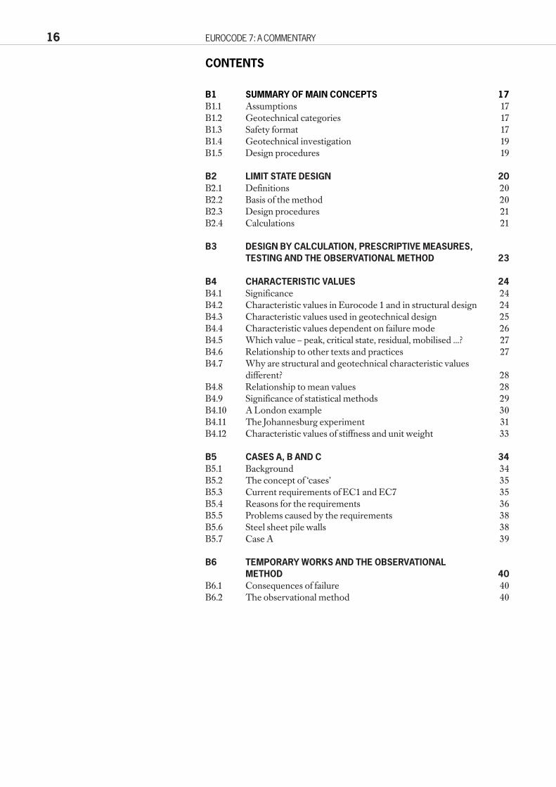
CONTENTS
B1 SUMMARY OF MAIN CONCEPTS 17B1.1 Assumptions 17B1.2 Geotechnical categories 17B1.3 Safety format 17B1.4 Geotechnical investigation 19B1.5 Design procedures 19
B2 LIMIT STATE DESIGN 20B2.1 Definitions 20B2.2 Basis of the method 20B2.3 Design procedures 21B2.4 Calculations 21
B3 DESIGN BY CALCULATION, PRESCRIPTIVE MEASURES, TESTING AND THE OBSERVATIONAL METHOD 23
B4 CHARACTERISTIC VALUES 24B4.1 Significance 24B4.2 Characteristic values in Eurocode 1 and in structural design 24B4.3 Characteristic values used in geotechnical design 25B4.4 Characteristic values dependent on failure mode 26B4.5 Which value – peak, critical state, residual, mobilised ...? 27B4.6 Relationship to other texts and practices 27B4.7 Why are structural and geotechnical characteristic values
different? 28B4.8 Relationship to mean values 28B4.9 Significance of statistical methods 29B4.10 A London example 30B4.11 The Johannesburg experiment 31B4.12 Characteristic values of stiffness and unit weight 33
B5 CASES A, B AND C 34B5.1 Background 34B5.2 The concept of ‘cases’ 35B5.3 Current requirements of EC1 and EC7 35B5.4 Reasons for the requirements 36B5.5 Problems caused by the requirements 38B5.6 Steel sheet pile walls 38B5.7 Case A 39
B6 TEMPORARY WORKS AND THE OBSERVATIONAL METHOD 40
B6.1 Consequences of failure 40B6.2 The observational method 40
16 EUROCODE 7: A COMMENTARY

B1 SUMMARY OF MAIN CONCEPTS
B1.1 AssumptionsAlthough it may well be applied elsewhere, it is important to realise that EC7-1is drafted for use in Western Europe. Assumptions which follow from this arelisted in Clause 1.4, which sets the standards for good practice to be followedon every project. The factors of safety used in the code are based on this goodpractice. Where standards of data collection, analysis, design, constructionand maintenance fall below those standards, a more conservative designapproach should be followed. Continuity between each of the stages of theproject is also assumed, with a free flow of information and data between theground investigators, designers and constructors.
The design process should therefore be an unbroken continuous process,with appropriately qualified and experienced personnel carrying out each stage.
Some problems in the interpretation of these assumptions are noted in C1.4.
B1.2 Geotechnical categoriesA flow diagram illustrating the recommended route throughgeotechnical design to EC7 is shown on Figure B1.1.
Clause 2.1 introduces the concept of GeotechnicalCategories. EC7 divides structures into GeotechnicalCategories 1, 2 or 3 according to a number of geotechnicaldesign requirements, principally related to the complexity ofthe structure and previous experience of the particularground conditions. Most engineered structures will fall incategory 2, whilst very simple designs may be in Category 1and complex problems fall into Category 3; Figure B1.2 is aflow diagram showing the decisions required incategorisation. The categories are used in the code toindicate the degree of effort required in site investigation and design. In C2.1, it is suggested that the categories alsoindicate the qualifications of the personnel required for the work.
Categorisation is not a mandatory part of the code, allreference to it being in application rules rather thanprinciples. Concern has been expressed, particularly byfoundation contractors, about its legal implications.
The intention is that a preliminary classification of astructure according to geotechnical category shouldnormally be made prior to the geotechnical investigations.The category should be checked and possibly changed ateach stage of the design and construction process, asindicated by the asterisks in Figure B1.1. The procedures of higher categories may be used to justify more economic designs, or where the designer considers them tobe appropriate.
B1.3 Safety formatIn common with all the Eurocodes, EC7 is based on theprinciples of limit state design. The application of this ingeotechnical engineering is discussed in B2. Calculations areprincipally to be carried out by applying partial safety factorsto characteristic values of soil parameters, which arediscussed further in B4. Design is not entirely based oncalculation, however, and use of observation and testing isalso encouraged, as noted in B3.
PART B IMPORTANT FEATURES OF EUROCODE 7 PART 1 17
*
*
Design Investigation[Ground Investigation]
(Clause 3.2)
NO
YES
Sufficient Information?
Ground Investigation Report(Clause 3.4)
Design
Geotechnical Design Report(Clause 2.8)
Construct works
*
** = Recategorise structure ( Clause 2.1)
*
CategoriseStructure
(Clause 2.1)
Preliminary Investigation[Desk Study](Clause 3.1)
Figure B1.1 The EC7 design process

18 EUROCODE 7: A COMMENTARY
N0
N0
YE
S
YE
S
YE
S
YE
S
Is th
e st
ruct
ure
“sm
all a
nd r
elat
ivel
ysi
mpl
e”?
Are
the
grou
nd c
ondi
tions
kno
wn
from
com
para
ble
expe
rienc
e to
be
suffi
cien
tly s
trai
ghtfo
rwar
d th
at r
outin
em
etho
ds m
ay b
e us
ed fo
r fo
unda
tion
desi
gn a
nd c
onst
ruct
ion?
If ex
cava
tion
belo
w th
e w
ater
tabl
e is
invo
lved
,do
es c
ompa
rabl
eex
perie
nce
indi
cate
that
it w
ill b
est
raig
htfo
rwar
d?
Is th
e si
te fr
ee fr
om a
bnor
mal
ris
ks s
uch
as u
nusu
al lo
adin
g or
sei
smic
ris
k?
Eg.
Sim
ple
1 an
d 2
stor
ey h
ouse
s an
d ag
ricul
tura
lbu
ildin
gs w
ith a
max
imum
col
umn
load
of
250k
N a
nd 1
00kN
/m fo
r w
alls
and
usi
ngco
nven
tiona
l typ
es o
f spr
ead
and
pile
dfo
unda
tions
.
Ret
aini
ng w
all a
nd e
xcav
atio
n su
ppor
t whe
reth
e di
ffere
nce
in g
roun
d le
vels
doe
s no
t exc
eed
2m.
Sm
all e
xcav
atio
ns fo
r dr
aina
ge w
orks
, pip
ela
ying
, etc
.
Cat
egor
y 1
Is th
e st
ruct
ure
very
larg
e or
unu
sual
?
Doe
s it
invo
lve
unus
ual o
r ex
cept
iona
llydi
fficu
lt gr
ound
?
Doe
s it
invo
lve
abno
rmal
ris
ks?
Are
the
load
ing
cond
ition
s un
usua
l or
exce
ptio
nal?
Is th
e st
ruct
ure
in a
hig
hly
seis
mic
are
a?
Eg.
Spr
ead
foun
datio
nsR
aft f
ound
atio
nsP
iled
foun
datio
nsW
all a
nd o
ther
str
uctu
res
reta
inin
g or
sup
port
ing
soil
or w
ater
Exc
avat
ions
Brid
ge p
iers
and
abu
tmen
tsE
mba
nkm
ents
and
ear
thw
orks
Gro
und
anch
ors
and
othe
r tie
bac
k sy
stem
sTu
nnel
s in
har
d, n
on fr
actu
red
rock
and
not
subj
ecte
d to
spe
cial
wat
er ti
ghtn
ess
or o
ther
requ
irem
ents
.
Cat
egor
y 2
Eg.
Str
uctu
res
or p
arts
of s
truc
ture
s w
hich
do
not
fall
with
in th
e lim
its o
f Geo
tech
nica
l Cat
egor
ies
1 an
d 2.
Cat
egor
y 3
YE
S
YE
S
YE
S
YE
S
YE
S
N0
N0
N0
N0
N0
N0
N0
Figu
re B
1.2
Geo
tech
nica
l cat
egor
isat
ion

B1.4 Geotechnical investigationIn Section 3, EC7-1 provides outline requirements for geotechnical siteinvestigation, dividing the activities into preliminary and design investigations.The preliminary investigation (EC7, 3.1 and 3.2.2) corresponds to what istraditionally referred to in the UK as a ‘Desk Study’. It identifies the groundrelated hazards which the structure will face both during construction (eg theneed for dewatering) and in the permanent condition (eg the need to resistwhatever onerous combination of loads is most critical). The designinvestigation (EC7, 3.2.3) corresponds to what used to be called in the UK‘Site Investigation’ and is now more properly referred to as the ‘GroundInvestigation’. It investigates the hazards identified in the preliminaryinvestigation and produces design parameters which are appropriate for thegeotechnical category. This process is illustrated in Figure B1.1.
The code requires that the final design is accompanied by formal reports,both factual and interpretative, of the investigations on which it is based. The
contractual issues which this raises arediscussed in C3.4. The factual report onthe design investigation is incorporatedin the ‘Ground Investigation Report’(EC7, 3.4) which also includesevaluation and interpretation of thedata. The Ground Investigation Reportcan be included in the ‘GeotechnicalDesign Report’ (EC7, 2.8) which alsoincludes design assumptions, designcalculations and the plan for sitesupervision and monitoring required bythe design.
Clause 3.3 also gives requirements forthe process of evaluating the mainground parameters used in calculations(generally characteristic values for EC7).Methods of carrying out field andlaboratory tests are not described in EC7Part 1, but in Parts 2 and 3 (see A2.5).
B1.5 Design proceduresThe later sections of EC7-1 consider thedesign of some specific types offoundations and other geotechnicalstructures. The code generally does notspecify the precise form of calculationsto be used, but states what criteria are tobe checked by the calculations.
Clause 2.8 requires that assumptions,data, calculations and results of theverification of safety and serviceabilitymust be recorded in a GeotechnicalDesign Report. The level of detail ofGeotechnical Design Reports will varygreatly, depending on the type of design.For simple designs, a single sheet may besufficient. An example of such a sheet isgiven in Figure B1.3.
The scope of the report includes aplan of supervision and monitoring, asappropriate, and the clause requires thatrelevant parts of the report must beprovided to the client.
PART B IMPORTANT FEATURES OF EUROCODE 7 PART 1 19
Job No.
Made by:
Checked by:
Approved by:
Date ......................
Date ......................
Date ......................
Sheet no of..............Job Title
Structure Reference:
Reports used:Ground Investigation report (give ref. date)Factual:
Interpretation:
Section through structure showing actions:
Codes and standards used (level of acceptable risk)
Assumed stratigraphy used in design with properties:
Description of site surroundings:
Information to be verified during construction.Notes on maintenance and monitoring.
Calculations (or index to calculations)
Figure B1.3 Single page geotechnical design report
‘NNeeww ssttaarrtt hhoouussiinngg ddeevveellooppmmeenntt
SSttrriipp ffoouunnddaattiioonnss
BBllooggggss IInnvveessttiiggaattiioonnss LLttdd rreeppoorrtt AABBCC//112233 ddaatteedd 2211 FFeebb 9955
DDiittttoo
EEuurrooccooddee 77LLooccaall bbuuiillddiinngg rreeggss
FFoorrmmeerrllyy aaggrriiccuullttuurraall llaanndd..GGeennttllyy ssllooppiinngg ((44°))
CChhaarraacctteerriissttiicc llooaadd 6600 kkNN//mm..LLooccaall eexxppeerriieennccee pplluuss LLooccaallBBuuiillddiinngg RReegguullaattiioonnss ((rreeff ......................................))iinnddiiccaatteess wwoorrkkiinngg bbeeaarriinnggpprreessssuurree ooff 110000 kkPPaa aacccceeppttaabbllee..TThheerreeffoorree aaddoopptt ffoooottiinnggss 00..66 mmwwiiddee,, mmiinniimmuumm ddeepptthh 00..55 mm((BBuuiillddiinngg RReeggss)) bbuutt ddeepptthh vvaarriieessttoo rreeaacchh cc
uu6600 kkPPaa ÐÐ tteesstt oonn
ssiittee..
TTooppssooiill aanndd vveerryy wweeaatthheerreedd ggllaacciiaall ttiillll uuppttoo 11 mm tthhiicckk,, oovveerrllyyiinngg ffiirrmm ttoo ssttiiffff ggllaacciiaallttiillll ((cc
uu6600 kkPPaa oonn ppoocckkeett ppeenneettrroommeetteerr))..
CCoonnccrreettee ccaasstt oonn uunn--ssoofftteenneedd ggllaacciiaall ttiillllwwiitthh cc
uu6600 kkPPaa ((ppoocckkeett ppeenneettrroommeetteerr))

B2 LIMIT STATE DESIGN
B2.1 DefinitionsLimit state design is a procedure in which attention is concentrated onavoidance of limit states. Limit states are defined as ‘states beyond which thestructure no longer satisfies the design performance requirements’ (EC1, 3.1(1)P). Strictly, it is the exceedence of a limit state which is not acceptable,though EC7 often refers to avoiding the occurrence of a limit state.
This definition of limit states is essentially practical and relates to thepossibility of damage, economic loss or unsafe situations. It is not directlyconcerned with states of stress in materials or distinctions between elastic andplastic behaviour, though designers may need to consider these in order todemonstrate that limit states will not be exceeded.
Limit state design is concerned with any state in which a structure does notsatisfy the design performance requirements. For example, cracking ordistortion which has no more consequence than giving a disappointingappearance constitutes a limit state, just as does a catastrophic collapse. Theseverities of these two limit states are obviously very different.
It has been found convenient to categorise limit states as ultimate orserviceability limit states. EC1 defines ultimate limit states as those associatedwith collapse or with other similar forms of structural failure (3.2(1)P).Serviceability limit states correspond to conditions beyond which specified servicerequirements for a structure or structural element are no longer met (3.3(1)P). Theserviceability requirements should generally be determined in contracts and/or inthe design (3.3(4)).
EC1, Section 3 adds more detail to this description of ultimate andserviceability limit states. For geotechnical design, it is important to note thatultimate limit states include failure by excessive deformation, ... loss of stability ofthe structure or any part of it. Hence, a state in which part of a structure becomesunsafe because of foundation settlement or other ground movements shouldbe regarded as an ultimate limit state, even if the ground itself has not reachedthe limits of its strength, to form a plastic failure mechanism. For example,large amounts of heave of plastic, over-consolidated London Clay haveoccurred over long periods following the removal of trees. While there is noquestion of the ground strength having reduced, to the degree that bearingcapacity failure is approached, the movements have been large enough toinduce collapse in a building, following loss of bearing in lintels over windowand door openings. The application of this concept to retaining walls is notedin EC7, 8.4(2).
Limit states are generally checked by considering design situations, inwhich adverse conditions apply; design values, which are deliberatelypessimistic, are used for both loads and material strengths. Design values areused in calculations for both ultimate and serviceability limit states, thoughthe values will usually be different for the two states. The Eurocodes specifyhow design values are to be derived. The design values required forserviceability limit states are often equal to the characteristic values ofparameters (formally, a partial factor of 1.0 is applied), but there is nofundamental reason why this must always be so. EC7 states that SLS designvalues will normally equal characteristic values for actions in 2.4.2(18) and formaterials in 2.4.3(13).
B2.2 Basis of the methodThe definitions considered above show that limit state design is concernedwith what might go wrong. Attention is concentrated on states which it isintended will not occur rather than on what, it is hoped, will actually happen.Occasional exceedence of serviceability limit states might be economicallytolerable, but generally ultimate limit states must be avoided. Thus the designshould have appropriate degrees of reliability (EC1, 2.1(1)P).
20 EUROCODE 7: A COMMENTARY

The aim of limit state design is to avoid limit states in general, and to makevery remote any possibility of an ultimate limit state. Ultimate limit states areintended to be unrealistic possibilities. Hence, in calculations, the codessometimes require the adoption of design values for parameters which areunrealistically pessimistic.
It may be questioned whether there is anything distinctive about limit statedesign, or whether the definitions are so broad that they incorporate alldesign processes. This is particularly relevant in geotechnical design, where,historically, there has been more consideration of plastic failure mechanisms –undesired states – than on working states of elastic stress. The distinctivefeature of limit state design is essentially one of emphasis, with attentionconcentrated on what might go wrong.
Limit state design is sometimes contrasted with permissible stress designin which attention is concentrated on prediction of the stresses in materials inthe intended working state. This terminology becomes confused if permissiblestresses at the limit states are considered – and there is no logical reason whythese should not be used. Hence it is preferable to contrast limit state designwith working state design.
Some of the pros and cons of limit state design have been discussed bySimpson (1997).
B2.3 Design proceduresThe basic limit state design procedure has two stages:a set up design situations;b show that limit states will not be exceeded in the design situations.
EC1, Clause 2.3 states: The selected design situations shall be sufficiently severe andso varied as to encompass all conditions which can reasonably be foreseen to occurduring the execution and use of the structure. Design situations are categorised aspersistent, transient and accidental situations, and the limit states relevant tothe various situations may vary. For example, for an accidental situation,which involves exceptional conditions, the structure may be required merelyto survive without collapse; in this case serviceability limit states would not be relevant. More information on design situations may be found in EC1, 2.3and EC7, 2.2.
The limit state method does not restrict the means by which it may bedemonstrated that limit states will not be exceeded in the design situations.Often, calculations will be used for this purpose, but other approaches providealternatives or supplements to design by calculation. These include loadtesting at full scale or on models, which is particularly relevant to design ofpiles and ground anchors (EC1, Section 8 and EC7, 2.6); prescriptivemeasures, in which well-established details are adopted without calculation(EC7, 2.5); and the Observational Method (EC7, 2.7). These methods arediscussed further under the relevant clauses in Part C.
The definition of serviceability limit states often requires the specificationof a limiting value of displacements or strain. It is essential that this isrealistically assessed as values representing an unacceptable condition.Unnecessarily severe values may lead to highly uneconomic design.
B2.4 CalculationsHistorically, the limit state method became popular at about the time thatpartial safety factors began to be adopted. The two are therefore often linked,though there is no fundamental connection between them. A calculationusing a global factor of safety or directly assessed pessimistic design valuescould be sufficient to demonstrate that limit states will not occur. It was notedabove that the limit state method does not necessarily require calculations asthe basis of design.
Limit state calculations are usually carried out by showing that the designproperties of materials are sufficient to withstand the design values of all
PART B IMPORTANT FEATURES OF EUROCODE 7 PART 1 21

applied actions (ie loads – see A2.8). The design values generally incorporateall the required safety elements, with no further overall factor of safety.Generally, design values of parameters, Xd, are derived from characteristicvalues, Xk, by applying partial factors γ:for actions: Fd = Fk × γfor materials: Xd = Xk / γ
The derivation of design values by applying partial factors to lesspessimistic characteristic values provides a means by which codes of practicecan exert some influence over the degree of pessimism of the design values.The concept of ‘characteristic’ values in geotechnical engineering is discussed in B4.
The limit state design method requires that all possible limit states areconsidered and eliminated, with ‘appropriate degrees of reliability’. In general,this will at least mean that ultimate and serviceability limit states must beconsidered. For geotechnical design, this puts an increased emphasis on theneed to consider deformations, but EC7 aims to discourage excessive orspurious attempts to calculate displacements.
The purpose of partial factors is generally stated to be to allow foruncertainties and inaccuracies in the values of the parameters (EC1, 9.3.1 and9.3.3). Some authorities deduce from this that the values of the partial factorsmay be derived from statistical studies of these uncertainties. In this approach,the factors used for ULS design have no bearing on the serviceability of thestructure. This contrasts with the use in BS 8002 of a ‘mobilisation factor’,which is effectively a partial factor, but its stated purpose is to prevent stresslevels in materials reaching a point at which displacements becomeunacceptable; that is, the factor’s role is mainly in serviceability.
Referring to partial factors on actions, Eurocode 1 takes a broader view in9.4.3(3): The values have been based on theoretical considerations, experience andback calculations on existing designs. The calibration of the ULS factors based onexperience and back calculations will necessarily mean that their values makesome provision for serviceability as well as ultimate requirements. EC7 notesin 2.4.1(7) that in some situations it is necessary to use factors applied in theanalysis of one limit state in order to cover another, for which calculations arenot reliable.
In the authors’ opinion, this pragmatic approach to the use of partial factorsis realistic. The factors adopted are inevitably calibrated against previousdesigns and therefore make some provision for serviceability as well asultimate safety. Where EC7 makes additional requirements for checks onserviceability, these should be followed, however.
22 EUROCODE 7: A COMMENTARY

B3 DESIGN BY CALCULATION, PRESCRIPTIVE MEASURES, TESTINGAND THE OBSERVATIONAL METHOD
The fundamental design requirements for limit state design are set out in EC7,2.1. In 2.1(7), it is stated that these requirements may be achieved by:a use of calculations;b adoption of prescriptive measures;c experimental models and load tests; ord an observational method.
It is clear that design based on calculation is not the only process envisaged.The same paragraph says that these four approaches may be used incombination. This often forms the basis of good geotechnical engineering.
Prescriptive measures (EC7, 2.5) involve conventional and generallyconservative details in the design, and attention to specification and control ofmaterials, workmanship, protection and maintenance. They may be used whencalculations are not available or not necessary. They could be used for design fordurability, for example, and will often be based on the observed performanceof existing structures. More generally, they might be used to make a quick,conservative design in cases where the cost of extensive site investigation andanalysis cannot be justified. In Hong Kong, the Geotechnical EngineeringOffice is preparing to publish a series of recognised prescriptive measures forstabilisation of small slopes, for example.
Design of piles and ground anchors has traditionally been based verylargely on load testing. This is in the category design by experimental models andload tests, in which confidence in the safety of the design depends on testresults, either in place of or in combination with calculations. This use of testresults in design is discussed further in EC7, 2.6, 7.5–7.7 and 8.8, and in E7, E8and E12. EC7 mentions the use of model testing in 2.6, but does not enlargeon this.
EC7, 2.7 is a specific clause about the Observational Method, which hasreceived a great deal of support from the geotechnical community. It is used inrecent publications Safety of New Austrian Tunnelling Method (NATM)Tunnels, by HSE and the CIRIA report on the Observational Method(Nicholson et al (1997)). Since the Observational Method relates mainly to thedesign of temporary works, it is considered further in B6.
PART B IMPORTANT FEATURES OF EUROCODE 7 PART 1 23

B4 CHARACTERISTIC VALUES
B4.1 SignificanceCharacteristic values of geotechnical parameters are fundamental to allcalculations carried out in accordance with the code. Their definition, ingeotechnical terms, has been the most controversial topic in the wholeprocess of drafting Eurocode 7. Some of the more difficult issues will beaddressed here. More straightforward matters will be left to Part C. The mostimportant text is in EC7, 2.4.3.
Two factors underlie the importance and controversy of characteristicvalues.a Calculations are to be carried out by applying partial safety factors to
characteristic values in order to obtain design values of parameters. Thepartial factors are specified by the code, so the selection of characteristicvalues is the main point in calculations at which engineers are to apply theirskills and judgment, with the possibility of dangerous mistakes.
b Engineers have always had the responsibility for selecting values ofmaterial parameters for calculations. This process has sometimes beenreferred to as a ‘black art’, and it is difficult to find helpful advice on thethought processes necessary to derive appropriate values from siteinvestigation and other information. In particular, the degree ofconservatism necessary in choosing values for design purposes is rarelydiscussed.
Eurocode 7’s definition of characteristic values is intended to make full use ofthe skills and judgment of experienced engineers, whilst helping lessexperienced engineers to choose values which are both reasonable and safe.This was, and remains, a major challenge.
B4.2 Characteristic values in Eurocode 1 and in structural designCharacteristic values, as used in Eurocode 7, are intended to comply withEurocode 1 as far as possible, whilst remaining true to principles of soundgeotechnical engineering. Although it arguably remains within the spirit ofEurocode 1, the definition adopted for geotechnical purposes differs from thatof Eurocode 1 in some important respects. To understand this, it is necessaryfirst to consider what Eurocode 1 says about characteristic values, Xk.
Eurocode 1, Subclause 9.3.3 states:The design value Xd of a material or product property is generally defined as:Xd = ηXk / γM or Xk / γMwhere:γM is the partial factor for the material or product property, given in ENVs 1992 to1999, which covers:● unfavourable deviations from the characteristic values;● inaccuracies in the conversion factors; and ● uncertainties in the geometric properties and the resistance model.
η is the conversion factor taking into account the effect of the duration of the load,volume and scale effects, effects of moisture and temperature and so on.
Characteristic values are introduced in Eurocode 1 Section 5 thus:(1)P Properties of materials (including soil and rock) or products are represented by
characteristic values which correspond to the value of the property having aprescribed probability of not being attained in a hypothetical unlimited test series.They generally correspond for a particular property to a specified fractile of theassumed statistical distribution of the property of the material in the structure.
(2) Unless otherwise stated in ENVs 1992 to 1999, the characteristic values shouldbe defined as the 5% fractile for strength parameters and as the mean value forstiffness parameters.Note: For operational rules, see annex D, for fatigue, information is given in annex B.
24 EUROCODE 7: A COMMENTARY

(3)P Material property values shall normally be determined for standardized testsperformed under specified conditions. A conversion factor shall be applied where itis necessary to convert the test results into values which can be assumed to representthe behaviour of the material in the structure or the ground (see also ENVs 1992 to 1999).
This text specifies the following features:a Characteristic values take account of the statistical distribution of the
property. That is, the range of uncertainty of the property is relevant totheir selection.
b They can normally be derived by a statistical process applied to a series oftests on specimens of the material. However, in principle they relate to ahypothetical, unlimited test series, so some correction may be required whentest series are limited.
c For strength properties, they are to correspond to the 5% low fractile of thetest results; this is the strength below which 5% of test results fall.
d Nevertheless, the characteristic values are said to represent the behaviour ofthe material in the structure or the ground, and corrections to test results maybe needed in order to achieve this.
e For stiffness, mean values are to be used. This is considered further in B4.12.
These definitions of characteristic value are clearly intended to be general.Eurocode 1 does not at this point mention the mode of failure or type of limitstate being discussed, or the severity of its consequences.
In structural design, characteristic values are generally defined usingstatistical procedures applied to the results of tests on material specimens.The specimen is generally not obtained from the structure and its relationship to material in the structure depends more on control ofworkmanship than on the designer’s observation or judgement. In thisrespect, the definition of characteristic value for ground materials given inEurocode 7 is distinctly different.
B4.3 Characteristic values used in geotechnical designIn Eurocode 7, the characteristic values of geotechnical material parametersare based on an assessment of the material actually in the ground and the waythat material will affect the performance of the ground and structure inrelation to a particular limit state (EC7, 2.4.3(2,3,4)). Field and laboratory testsare to be used, but they are only one means of assessing what is in the ground;characteristic values are not derived directly or solely from the test results.Statistical manipulation of test results will generally have only a minor role inthis process, if any. The resulting value is inevitably subjective to some extent,being influenced by the knowledge and experience of the designer. However,this is considered preferable to an alternative, mechanical approach which hasarithmetic objectivity but jettisons established engineering knowledge.
In many situations, the known geology of a stratum, and existingexperience of it give a fairly good indication of its parameter values. Soil testsare used as a check. It is good practice to base the selection of characteristicvalues on a combination of well established experience and the test results(EC7, 2.4.3(2,4)). If unusually good test results are obtained, engineers willnormally spot this and treat them with greater caution, unless furtherinvestigation is possible to establish that they are relevant. Unusually badresults may lead to further investigation, or may otherwise be taken at facevalue unless the evidence of other experience is overwhelming.
Construction activities may affect the properties of the ground, adversely orbeneficially (EC7, 2.4.3(4)). Common examples occur during boring ordriving of piles, or excavating to a level on which concrete will be cast. Inmany cases this will occur after any investigation and testing are complete.Nevertheless, the characteristic value is to account for these construction
PART B IMPORTANT FEATURES OF EUROCODE 7 PART 1 25

effects. Information from previous experiences and publications willcontribute to the selection of characteristic values in these circumstances.
Having reviewed these items, EC7 says that the characteristic value of a soil orrock parameter shall be selected as a cautious estimate of the value affecting theoccurrence of the limit state (EC7, 2.4.3(5)). This is standard engineeringpractice. The relationship of the ‘cautious value’ to mean values will beconsidered in B4.9 to B4.11 below.
B4.4 Characteristic values dependent on failure modeThe characteristic value of one parameter in one stratum is not necessarily thesame for two different failure modes. It may depend on the extent to which aparticular mode averages out the variable properties of the stratum (EC7,2.4.3(4, 6)).
Figure B4.1 shows a small industrial building, founded on pad footings neara long slope. The underlying materials are estuarine beds, mainly of sandswith some impersistent lenses of clay occurring at random. In this type ofsituation, the design of the footings would probably assume that they might befounded on clay, the more adverse condition for foundation design.
(An alternative could be, in some cases, to require an inspection and probe ateach footing, so avoiding this adverse condition.) On the other hand, whenthe possibility of a large slip surface is considered, it is inconceivable that thiswill lie entirely, or even mainly in clay. In this type of situation, thecharacteristic values for strength parameters of the beds would be different for
the footing design and for the slip, though their safetyis controlled by the same stratum in both cases.
Figure B4.2 shows results of a CPT test in a mixed,estuarine deposit which has been overconsolidated,variably, by desiccation. A piled foundation is to beconstructed in this material. If the piles are of fixedlength (perhaps limited by construction equipment),the characteristic values of soil strength for the baseand shaft may be quite different. The shaft averagesthe properties of a large amount of material, frommany periods of deposition, whilst the base could beformed in one of the weaker layers. In this case thecharacteristic values of soil strength for the shaftwould be higher than that for the base, in the samedeposit. On the other hand, if the constructionprocess allows the base to be tested, by pile driving for example, the characteristic value for the base could be higher that the averaged value used for theshaft. This discussion must also be modified to takeaccount of any systematic variation of strength with depth.
26 EUROCODE 7: A COMMENTARY
Estuarine bedsSands with Clay lenses
Figure B4.1 Small building on estuarine beds near slope
0
5
10
Dep
th (
m)
0 5 10 15 20Cone Resistance (MPa)
Figure B4.2 CPT results in variable deposit

B4.5 Which value – peak, critical state, residual, mobilised ...?The question has been asked: Which value is the characteristic value? It issometimes necessary to chose from one of the following, depending oncircumstances:a peak, critical state or residual shear strength;b ultimate strength or a ‘mobilised’ value;c strength of intact material or strength on joints;d strength at first loading or after repeated loading;e stiffness of intact rock or of the jointed material;f stiffness on first loading, or on unload-reload.
In all cases, the answer of Eurocode 7 is: the one that is relevant to the preventionof the limit state under consideration. EC7 does not differ in this respect fromnormal practice. For some particular situations, the code is able to specifywhich of these values is relevant. For example, where concrete is to be castagainst ground, which might therefore be disturbed, the critical state value forthe angle of shearing resistance is required (EC7, 8.5.1(4)). In consideringrocks, a study of the joint patterns will determine whether intact or jointstrength is relevant (EC7, 3.3.9).
This answer to the question is not the same as: the one which would becomerelevant if the limit state was not prevented. For example, in most plastic clays, if aslip occurred, the angle of shearing resistance would eventually fall to theresidual value. Nevertheless, it is not necessary to design for residual strengthin clays which have not previously slipped. Similarly, it may be unnecessary todesign for critical state values, though brittleness and ductility must beconsidered, as noted in EC7, 2.1(9) and C2.1.
Generally the strength to be used in Eurocode 7 is the maximum availableto prevent collapse, not a mobilised value.
B4.6 Relationship to other texts and practicesWith regard to characteristic values, the intention of the drafters of EC7 wasto clarify existing practice, rather than to introduce something new. The mainproblem was the difficulty of defining existing practice. Nevertheless, sometexts give helpful indications of the way in which parameter values are to bechosen and it is relevant to compare these with characteristic values.
CIRIA Report 104 suggests that design may be based on moderatelyconservative values of parameters. ‘Moderately conservative’ is defined (p 40)as meaning conservative best estimate. It could be objected that the latter term iscontradictory, since a value cannot be both conservative and a best estimatesimultaneously. CIRIA 104 states that this approach is used most often in practiceby experienced engineers. The authors consider that the conservative best estimatevalues of CIRIA 104 are essentially the same as the characteristic values of EC7.
In BS 8002, design values of soil strength (ie values entered intocalculations) are derived by factoring representative values. For effective stress parameters, there is a further requirement that the design value mustnot exceed the representative critical state value. A representative value isdefined (1.3.17) to be a conservative estimate of the mass strength of the soil.‘Conservative values’ are further defined (1.3.2) as values of soil parameterswhich are more adverse than the most likely values. They may be less (or greater)than the most likely values. They tend towards the limit of the credible range ofvalues. The authors suggest that this definition makes representative valuesessentially the same as moderately conservative values in CIRIA 104 andcharacteristic values in EC7.
The Dutch standard NEN 6740 (in Dutch) provides a more statisticalapproach to derivation of characteristic values. German recommendations forwaterfront structures (EAU (1980, p38)) discuss the statistical background tocharacteristic values, and also provide some more pragmatic suggestions:When a large number of shear parameters have been determined, the characteristicvalue can also be estimated as being that value which occurs immediately below the
PART B IMPORTANT FEATURES OF EUROCODE 7 PART 1 27
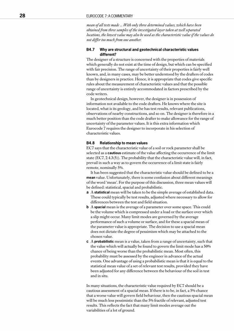
mean of all tests made ... With only three determined values, which have beenobtained from three samples of the investigated layer taken at well separatedlocations, the lowest value may also be used as the characteristic value if the values donot differ too much from one another.
B4.7 Why are structural and geotechnical characteristic valuesdifferent?
The designer of a structure is concerned with the properties of materialswhich generally do not exist at the time of design, but which can be specifiedwith fair precision. The range of uncertainty of their properties is fairly wellknown, and, in many cases, may be better understood by the drafters of codesthan by designers in practice. Hence, it is appropriate that codes give specificrules about the measurement of characteristic values and that the possiblerange of uncertainty is entirely accommodated in factors prescribed by thecode writers.
In geotechnical design, however, the designer is in possession ofinformation not available to the code drafters. He knows where the site islocated, what is its geology, and he has test results, relevant publications,observations of nearby constructions, and so on. The designer is therefore in amuch better position than the code drafter to make allowance for the range ofuncertainty of the parameter values. It is this extra information whichEurocode 7 requires the designer to incorporate in his selection ofcharacteristic values.
B4.8 Relationship to mean valuesEC7 says that the characteristic value of a soil or rock parameter shall beselected as a cautious estimate of the value affecting the occurrence of the limitstate (EC7, 2.4.3(5)). The probability that the characteristic value will, in fact,prevail in such a way as to govern the occurrence of a limit state is fairlyremote, nominally 5%.
It has been suggested that the characteristic value should be defined to be amean value. Unfortunately, there is some confusion about different meaningsof the word ‘mean’. For the purpose of this discussion, three mean values willbe defined: statistical, spacial and probabilistic.a A statistical mean will be taken to be the simple average of established data.
These could typically be test results, adjusted where necessary to allow fordifferences between the test and field situation.
b A spacial mean is the average of a parameter over some space. This couldbe the volume which is compressed under a load or the surface over whicha slip might occur. Many limit modes are governed by the averageperformance of such a volume or surface, and for these a spacial mean ofthe parameter value is appropriate. The decision to use a spacial mean does not dictate the degree of pessimism which may be attached to thechosen value.
c A probabilistic mean is a value, taken from a range of uncertainty, such thatthe value which will actually be found to govern the limit mode has a 50%chance of being worse than the probabilistic mean. Most often, thisprobability must be assessed by the engineer in advance of the actualevents. One advantage of using a probabilistic mean is that it is equal to thestatistical mean value of a set of relevant test results, provided they havebeen adjusted for any difference between the behaviour of the soil in testand in situ.
In many situations, the characteristic value required by EC7 should be acautious assessment of a spacial mean. If there is to be, in fact, a 5% chancethat a worse value will govern field behaviour, then the cautious spacial meanwill be much less pessimistic than the 5% fractile of relevant, adjusted testresults. This reflects the fact that many limit modes average out thevariabilities of a lot of ground.
28 EUROCODE 7: A COMMENTARY

Figure B4.3 shows the results of a series of test results fromwhich a Young’s modulus is to be obtained for calculation ofsettlement beneath a foundation. There is a clear increase ofstiffness with depth, but the designer has checked that there is nosystematic variation of the test results with position on the site, sothe variations shown can be treated as random. The foundationwill load a large volume of ground and it is unreasonable to assumethat its settlement could be determined by material from the lowerend of the range of variation, such as the lowest 5% fractile. Asuggested profile representing a cautious mean is shown on thefigure. This could be used as the characteristic stiffness, varyingwith depth.
Figure B4.4 shows the same data and characteristic profile asFigure B4.3, with the statistical mean, obtained by linearregression, added. It can be seen that these two are fairly similar inthis case. In general, where the range of possible parameter valuesis narrow, it will be acceptable to adopt a statistical mean as thecharacteristic value, the cautious spacial mean. However, wherethe range of values which could govern the limit mode is large, thecautious spacial mean should be more pessimistic than thestatistical mean.
Characteristic values for stiffness parameters are consideredfurther in B4.12.
There are some situations in which spacial means are notrelevant, or, at least, must be chosen so specifically that they arenot easily recognised as means. For example, if stability of a rockcutting is being considered, the mean strength of the rock may beof no relevance: what is needed is the strength along joints whichare inclined towards the cutting. It could be argued, of course, thatit is the (spacial) mean strength of the joints which is needed.Similarly, for a small foundation or the base of a pile, the meanstrength of the stratum may be irrelevant if there is a possibilitythat the small zone of soil affecting the foundation is less strong. Incases such as these, the characteristic value is considerably morepessimistic than the statistical (or probabilistic) mean for thestratum as a whole.
One alternative approach, which defines the characteristic valueas the statistical mean (or possibly the probabilistic mean), mightyet find favour in the Eurocodes. In this, the designer is given somediscretion in the value of the partial factors, depending on hisassessment of the uncertainty of the parameter.
B4.9 Significance of statistical methodsEC7 states that statistical methods may sometimes be helpful inassessing characteristic values, but that they should allow a prioriknowledge of comparable experience with ground properties to be takeninto account for example by means of Bayesian statistical methods (EC7,2.4.3(6)). This demands a high order of statistical technique,available from very few designers who have committed their timeto training and experience in geotechnical engineering. Attemptsby statisticians to tackle geotechnical design have often ended inridicule, and it is very difficult for one person to have a sufficientgrasp of both disciplines that he can combine them sensibly.
Nevertheless, some pointers to more general rules forassessment of data might be obtained from statistical analysis.Schneider (1997) has proposed that, where a spacial mean isrelevant, the characteristic value might be taken as half a standarddeviation from the mean. Trials, like the one described in B4.11below, suggest that this rule could be a useful guide.
PART B IMPORTANT FEATURES OF EUROCODE 7 PART 1 29
0
5
10
15
200 10 20 30 40 50 60 70
Young’s modulus, E (MPa)
Dep
th (
m)
Characteristic
Figure B4.3 Profile of Young’s modulus measurements
0
5
10
15
200 10 20 30 40 50 60 70
Young’s modulus, E (MPa)
Dep
th (
m)
Characteristic Statisticalmean
Figure B4.4 Characteristic and statistical mean lines

For some specific problems, statistical studies have proved very useful.Studies of correlation distances in slope stability problems (Vanmarcke (1977))and of variability in cone penetrometer testing (Been and Jefferies (1993))provide interesting examples.
B4.10 A London exampleFigure B4.5 shows the results of a series of undrained shear strengthmeasurements in London Clay. The measurements were made usingunconsolidated undrained triaxial tests. A statistical mean line has been drawnthrough the data and it is clear that undrained strength increases with depth.A characteristic line is required, and this should depend on how thecharacteristic values will be used – what is the limit mode being considered?For example, if the undrained strength is needed for calculation of ground
30 EUROCODE 7: A COMMENTARY
0
4
8
12
16
20
24
28
32
4003002001000
Dep
th b
elow
top
of L
ondo
n C
lay
(m)
Undrained shear strength (kPa)
BH1 BH2 BH3
Cautious(local)
Cautious(average)
Mean
Figure B4.5 Undrained shear strengths measured at one siteusing 100 mm diameter UU triaxial tests
0
4
8
12
16
20
24
28
32
0
Dep
th b
elow
top
of L
ondo
n C
lay
(m)
BH1 BH2 BH3
10 20 30 40 50 60SPT blowcount, N (blows/300mm)
Figure B4.6 SPT results from tests at the same site
0
4
8
12
16
20
24
28
32
4003002001000
Dep
th b
elow
top
of L
ondo
n C
lay
(m)
Undrained shear strength (kPa)
BH1 BH2 BH3
SPT
Adjacent sites
Figure B4.7 SPT results and results from adjacent sitescompared with the UU triaxial results
0
4
8
12
16
20
24
28
32
4003002001000
Dep
th b
elow
top
of L
ondo
n C
lay
(m)
Undrained shear strength (kPa)
BH1 BH2 BH3
SPT
Adjacent sites Characteristic
Figure B4.8 An assessment of a ‘characteristic’ profile ofundrained strength

movements around a retaining wall, a value such as the ‘cautious (average)’value shown on the figure could be used. However, for a problem in whichfailure might take place in a small zone of soil, such as an isolated foundationplaced at a deep level, a more cautious value – the ‘cautious (local)’ value –should be adopted. From these boreholes, results from standard penetrationtests were also available, as shown in Figure B4.6. In London Clay, there isusually a constant factor between standard penetration and undrained shearstrength results; the factor is about 4.5 to 5. However, if the mean line from theSPT results is transferred onto the undrained strength plot, as in Figure B4.7,it appears that the normal correlation does not work. In fact, the measuredundrained strengths are remarkably high: they are consistent with very lowwater contents, which were measured, but this might simply mean that thesamples had dried out on the way to the laboratory, though there was noreason to suspect this. Figure B4.7 also shows lines representing mean valuesthrough data from other nearby sites, both for undrained shear strength andSPT results. The usual close correlation applies to these, and it is clear that theundrained strengths for the new site are remarkably high.
On the basis of these inconsistent data sets, what value should be used asthe characteristic undrained strength? The values measured in the triaxialtests should not be ignored, but the SPT results and the data from adjacentsites should also affect the decision. The characteristic value proposed forthese data is shown on Figure B4.8. This is less than the initial assessments inFigure B4.5, which were based on the triaxial results only, and is closer to alower bound of this particular set of triaxial results.
Engineers often need to follow this sort of process when trying to interpretreal data. It may be that statistical methods could trace a similar logicalsequence. However, this would require quite advanced methods and anystatistical approach which failed to take account of the diverse array of data,typically available, would be harmful to the design process.
B4.11 The Johannesburg experimentFigure B4.9 shows a set of ‘relevant’ test results for the angle of shearingresistance of a soil stratum. In Johannesburg, an audience of geotechnicalpractitioners was told that there was no systematic variation of these resultsand the limit mode would average a large body of the material. Having beenintroduced to EC7, they were asked to assess the characteristic value theywould adopt. The reader is invited to make his own assessment.
PART B IMPORTANT FEATURES OF EUROCODE 7 PART 1 31
10
8
6
4
2
030 31 32 33
Angle of shearing resistance (°)
Red
uced
leve
l (m
)
34 35 36 37 38 39 40
Figure B4.9 Measured angle of shearing resistance (1)
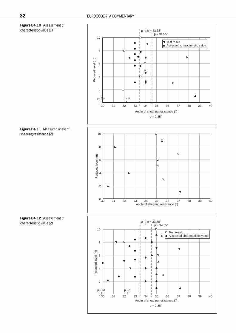
32 EUROCODE 7: A COMMENTARY
µ = 34.55°
σ = 2.35°
µ - 2σ µ - σ
10
8
6
4
2
030 31 32 33
Angle of shearing resistance (°)
Red
uced
leve
l (m
)
34 35 36 37 38 39 40
µ - σ = 33.38°12
Test resultAssessed characteristic value
Figure B4.10 Assessment ofcharacteristic value (1)
10
8
6
4
2
030 31 32 33 34 35 36 37 38 39 40Angle of shearing resistance (°)
Red
uced
leve
l (m
)
Figure B4.11 Measured angle ofshearing resistance (2)
µ = 34.55°
σ = 2.35°
µ - 2σ µ - σ
10
8
6
4
2
0 30 31 32 33
Red
uced
leve
l (m
)
34 35 36 37 38 39 40
µ - σ = 33.38°12
Test resultAssessed characteristic value
Angle of shearing resistance (°)
Figure B4.12 Assessment ofcharacteristic value (2)

The assessments made in Johannesburg are shown on Figure B4.10,together with the mean and values half and two standard deviations from themean. The assessments cluster around half a standard deviation from themean, as suggested by Schneider. Comments from the audience were thatthey felt that the assessment they had made was essentially the same as theywould previously have made in geotechnical design practice.
The same audience was then shown Figure B4.11. Again the reader isinvited to make an assessment of characteristic value. The Johannesburgresults, shown in Figure B4.12, were more uncertain in this case, despite thefact that the data had the same mean and standard deviation. Engineeringexperience was suggesting that the low values on this graph could not bedismissed so easily.
This experiment is considered to support the idea that ‘half a standarddeviation from the mean’ is a useful guide, whilst also suggesting that areliance on statistics alone would be dangerous.
B4.12 Characteristic values of stiffness and unit weightIt was noted in B4.2 that EC1, 5(2) defines characteristic values for stiffness tobe mean values. The context of this definition is probably ULS structuraldesign, in which values of stiffness are needed for analysis, but they rarely playa dominant part in determining the occurrence of a limit state.
In problems involving ground-structure interaction, however, the stiffnessof the ground is often a very important parameter. In these cases, the use of amean value for stiffness is questionable, since the calculations would thenimply a 50% probability that the limit state would be exceeded, for the givendesign loads. If the limit state under consideration is a SLS for whichdisplacements are being derived, partial load factors would be unity, sodisplacements calculated using a true ‘mean value’ stiffness would be bestestimates, with no reserve of safety. In design practice, engineers rarely takethis approach, preferring to make a more pessimistic estimate when there issignificant uncertainty. EC1, 5(2) is under review in the light of the foregoingreasoning (early 1998).
EC7-1 therefore uses the same definition of characteristic value for stiffnessas for strength. That is, a cautious estimate, not a mean value.
In assessing the occurrence of a limit state, a further parameter is involved,besides stiffness. This is usually a ‘limiting value’ of displacement or distortion(EC7, 2.4.6). It would, in principle, be possible to include sufficientconservatism in the specified limiting value that the actual occurrence of limitstates could be made ‘sufficiently improbable’, even though mean values wereused for stiffness. However, this would mean that the limiting values shouldbe chosen in relation to the level of uncertainty of ground stiffness, which issomewhat irrational.
EC7’s definition of characteristic value also applies to the unit weight of soiland rock. However, the uncertainty about unit weight is usually sufficientlylow that there is no need to make a distinction between mean and cautiousvalues. For fill materials behind retaining walls, special checks are required by8.3.1.1. Variability of unit weight is considered further in B5.4.2.
PART B IMPORTANT FEATURES OF EUROCODE 7 PART 1 33

B5 CASES A, B AND C
B5.1 Background
B5.1.1 OriginsThe adoption, meaning and purpose of ‘Cases A, B and C’ have competedwith characteristic values to be the most debated aspect of EC7. The cases aresets of partial factors to be applied to actions and to soil material properties.Their function is similar to the ‘load cases’ familiar to structural design, buttheir scope is extended to include factors on soil materials as well as loads. Allthree cases refer to design calculations for ultimate limit state, and values ofthe partial factors are given in the Table below (taken from Table 2.1 of EC7)].
Table B5.1 Partial factors – ultimate limit states in persistent and transient situationsActions Ground PropertiesPermanent Variable tan φ c' cu qu
[a]
Unfavourable Favourable Unfavourable
Case A [1.00] [0.95] [1.50] [1.1] [1.3] [1.2] [1.2]Case B [1.35] [1.00] [1.50] [1.0] [1.0] [1.0] [1.0]Case C [1.00] [1.00] [1.30] [1.25] [1.6] [1.4] [1.4]
[a] Compressive strength of soil or rock
Cases A, B and C are first defined in Eurocode 1, Table 9.2, which isreproduced as Figure C2.1. This comes in the middle of a section which dealswith combination rules for actions (ie load combinations), and the three casessupplement these, rather than providing an alternative. Table 9.2 of EC1 hassome important footnotes which will be discussed later.
The origin of Cases A and B lies in structural engineering codes: they are theload combinations considered for ‘stability’ and ‘strength’. In this structuralcontext, ‘stability’ refers to situations in which loads balance each other so thatthere is negligible reliance on the strength of a structure for safety. Typicalstructures of this type include canopies, and many structures duringconstruction, including both structural frames and balanced cantileverbridges. Case A is derived from such ‘stability’ considerations, requiring areduction factor to be applied to weight which acts in a stabilising manner. Inthe majority of structures, structural strength is a dominant feature in ensuringsafety, and for these the partial load factors of Case B are similar to the basicrequirements of BS 8110.
Case C came from earlier drafts of Eurocode 7. It has a unit factor onpermanent loads (generally weight) and a relatively small factor on variableloads. EC1 and EC7 in combination make it clear that in Case C the mainfactors are applied to the strength of ground materials. Thus, in Case B thenon-unit factors are all on loads and in Case C mainly on ground strength. Inall three cases, the values of partial factors to be applied to strength ofstructural materials are to be taken from the other Eurocodes, as relevant;they do not, in general, vary between cases.
The use of the three cases in EC1 Table 9.2 came about largely to assistintegration of EC7 with the other codes, and EC7 therefore follows theconcept of the three cases. However, it uses Case A in a special way byapplying it to potentially buoyant structures, which depend on a balance ofweight and water pressure, often with ground strength playing only a minorrole. EC7 recognises that there may be many situations which depend largelyon the balance of forces, but in which soil strength nevertheless plays a role. So,even for Case A, partial factors are applied to the strength of ground materials.
An example of the use of the three cases in checking the ultimate limit stateof a simple, potentially buoyant structure is given in E18. The reader may findit helpful to refer to that example to clarify the concepts described above,before studying the rest of this section.
34 EUROCODE 7: A COMMENTARY
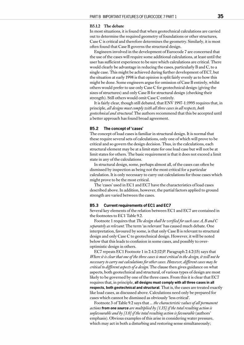
B5.1.2 The debateIn most situations, it is found that when geotechnical calculations are carriedout to determine the required geometry of foundations or other structures,Case C is critical and therefore determines the geometry. Similarly, it is mostoften found that Case B governs the structural design.
Engineers involved in the development of Eurocode 7 are concerned thatthe use of the cases will require some additional calculations, at least until theuser has sufficient experience to be sure which calculations are critical. Therewould clearly be advantage in reducing the cases, particularly B and C, to asingle case. This might be achieved during further development of EC7, butthe situation at early 1998 is that opinion is split fairly evenly as to how thismight be done. Some engineers argue for omission of Case B entirely, whilstothers would prefer to use only Case C for geotechnical design (giving thesizes of structures) and only Case B for structural design (checking theirstrength). Still others would omit Case C entirely.
It is fairly clear, though still debated, that ENV 1997-1:1995 requires that, inprinciple, all designs must comply with all three cases in all respects, bothgeotechnical and structural. The authors recommend that this be accepted untila better approach has found broad agreement.
B5.2 The concept of ‘cases’The concept of load cases is familiar in structural design. It is normal thatthese require several sets of calculations, only one of which will prove to becritical and so govern the design decision. Thus, in the calculations, eachstructural element may be at a limit state for one load case but will not be atlimit states for others. The basic requirement is that it does not exceed a limitstate in any of the calculations.
In structural design, some, perhaps almost all, of the cases can often bedismissed by inspection as being not the most critical for a particularcalculation. It is only necessary to carry out calculations for those cases whichmight prove to be the most critical.
The ‘cases’ used in EC1 and EC7 have the characteristics of load casesdescribed above. In addition, however, the partial factors applied to groundstrength are varied between the cases.
B5.3 Current requirements of EC1 and EC7Several key elements of the relation between EC1 and EC7 are contained inthe footnotes to EC1 Table 9.2.
Footnote 1 requires that The design shall be verified for each case A, B and Cseparately as relevant. The term ‘as relevant’ has caused much debate. Oneinterpretation, favoured by some, is that only Case B is relevant to structuraldesign and only Case C to geotechnical design. However, it will be notedbelow that this leads to confusion in some cases, and possibly to over-optimistic design in others.
EC7 repeats EC1 Footnote 1 in 2.4.2(12)P. Paragraph 2.4.2(15) says thatWhere it is clear that one of the three cases is most critical to the design, it will not benecessary to carry out calculations for other cases. However, different cases may becritical to different aspects of a design. The clause then gives guidance on whataspects, both geotechnical and structural, of various types of design are mostlikely to be governed by one of the three cases. From this it is clear that EC7requires that, in principle, all designs must comply with all three cases in allrespects, both geotechnical and structural. That is, the cases are treated exactlylike load cases, as discussed above. Calculations need only be prepared forcases which cannot be dismissed as obviously ‘less critical’.
Footnote 3 of Table 9.2 says that ... the characteristic values of all permanentactions from one source are multiplied by [1.35] if the total resulting action isunfavourable and by [1.0] if the total resulting action is favourable (authors’emphasis). Obvious examples of this arise in considering water pressure,which may act in both a disturbing and restoring sense simultaneously;
PART B IMPORTANT FEATURES OF EUROCODE 7 PART 1 35

it would be irrational to factor the disturbing and restoring components of thesame pressure differently.
For retaining walls, Paragraph 2.4.2(17) of Eurocode 7 effectively defines‘the ground’ as one source. That is, it says that All permanent characteristic earthpressures on both sides of a wall are multiplied by [1.35] if the total resulting actionis unfavourable and by [1.0] if the total resulting action is favourable (authors’emphasis). Since the term ‘earth pressures’ is defined, earlier in the sameclause, to include water pressures, it is clear that this factor of 1.35 applied toall earth pressures will have the effect of increasing bending moments andshear forces in the same ratio.
Paragraph 2.4.2(17) accepts that in some cases it is physically unreasonableto increase earth pressures, especially water pressures, by the factor 1.35. Forthese situations, EC7 allows the alternative of carrying out the calculationsusing unfactored characteristic earth pressures, then multiplying resultingbending moments and internal forces by 1.35, for Case B. EC7 says that thistreats the factors on actions in EC7, Table 2.1 as ‘model factors’.
Although the statements in 2.4.2(17) are restricted to earth pressures, theauthors recommend that this approach can be used more widely, but onlywhere direct application of the factor to earth pressures or to weight of earthleads to forces which are physically unreasonable.
Footnote 5 of EC1 Table 9.2 acknowledges that the factors applied toground properties in Cases B and C may be different, as is required by EC7Table 2.1. Footnote 6 confuses matters, however, stating that the use of designground properties may be introduced in accordance with ENV 1997 instead ofusing γG [1.35] and γQ [1.50]. These words effectively describe Case C, whichis presented as an ‘additional’, rather than ‘alternative’, requirement in EC7.
Footnote 6 notes that a model factor may be used with Case C, and thispossibility is also mentioned in EC7. Paragraph 2.4.2(15) says that a modelfactor may be introduced as relevant for structural design, and a similarstatement is made in 8.6.6(4) in relation to retaining structures. However, noboxed values are offered for these factors and none are supplied in the British NAD. Information on the possible future use of model factors isincluded in D2.2.
The only specific value attached to a model factor in EC7 is the use of[1.35], noted above, where it would be physically unreasonable, in Case B, tomultiply earth and water pressures by this factor.
B5.4 Reasons for the requirementsThere are two main arguments in favour of the approach that, in principle, alldesigns must comply with all three cases in all respects, both geotechnical andstructural. These are:a the need to have equilibrium in structural calculations, andb the possibility that one case alone might be lead to over-optimistic design.
B5.4.1 Equilibrium in structural calculationsThere has long been controversy over the choice of the factors 1.35 and 1.5 forstructural design. Some geotechnical engineers have argued that factors onweight should always be 1.0, and this view is supported by some structuralengineers in the UK and, more generally, in Scandinavia. Simpson (1992)suggested that the factor 1.35 may be reasonable, in structural design, if it isviewed as an allowance for uncertainty of load path as well as of weight itself.The same paper argued that the factor 1.35 was not relevant to geotechnicaldesign, but the considerations presented below are now thought to outweighthis view.
There is no real prospect that the factors 1.35 and 1.5 will be changed inEurocodes 1 to 4, at least, or in their NAD’s for most countries, including theUK. It is therefore necessary that EC7 enables designers to complete thedesign of structures in which these factors have been applied to loads in thestructural calculations. This becomes impossible if the geometry of the
36 EUROCODE 7: A COMMENTARY

structure cannot provide equilibrium,at its interface with the ground, withthese factored loads.
Figure B5.1 shows the designrequirements for a retaining wallwhich is founded on very goodground and is propped at its toe, soneither bearing capacity nor slidingare at issue. Eurocode 7 has no‘middle third rule’ or specified factorof safety against overturning, thoughSubclause 6.5.4 considers footingswith highly eccentric loads. Analysisof this wall to ULS Case C requires afooting width of 6.6 m, beingdetermined by the eccentricity of the resultant force between thefooting and the ground. However, ifthis width is used in a calculation forCase B it is found that the resultantforce is more eccentric and does notpass through the footing; a width of7.0 m is required. Hence a structural
designer would be led to an impasse. (For comparison, a conventional designrequiring a factor of safety on ‘overturning’ of 2.0 would require a footing widthof 9.05 m, whilst a design to BS 8002 would require 6.25 m. For unfactoredcharacteristic conditions, a footing width of 5.4 m would prevent overturning.)
Similar problems may occur for other structures subject to large lateralloads, such as chimneys and bridge piers. For retaining walls, the problembecomes worse when there is water pressure in the backfill, or fill of lowdensity or low angle of shearing resistance is used. A further exampleinvolving a tension-piled structure is noted in E12.
Problems of this type only affect a minority of designs, but they occursufficiently often to require that they are accommodated by the basicapproaches of EC7.
B5.4.2 Insufficient safety in one case aloneFew engineers who have studied this problem would argue for omitting Case C and using Case B alone. Since the strength of soil is generally derivedfrom friction, simply increasing its design weight, in slope stabilitycalculations, for example, provides no safety margin. In principle, it might bepossible to determine which zones of soil have a net disturbing effect andwhich a net restoring effect, and to factor the unit weights of these separately,but in practice this would be very difficult. In any case, the idea of factoring the unit weight of ground has little appeal as it leads to situations too remotefrom reality.
If Case B were omitted in the structural calculations for retaining walls,such as that shown in Figure B5.1, the ‘load factor’ on bending moment forultimate limit state structural design would be as low as 1.2 to 1.25 for dry soil,and even lower if the soil is saturated. This is uncomfortably low, particularlyfor walls of masonry or unreinforced concrete which have little ductility andability to release unexpectedly high earth pressures. (Design of the wallstructure for compaction pressures is discussed in C8.6.6.)
Similarly, for foundations subject mainly to permanent load, if Case B isomitted, the factor of safety on some structural stresses falls to unity for ULSdesign. (Shear stresses in spread foundations are one example.) It is clear thatthis approach cannot be acceptable to structural designers and could not beagreed with the drafters of the other Eurocodes.
PART B IMPORTANT FEATURES OF EUROCODE 7 PART 1 37
0.3
1.2
1m10
m
Prop B?
Water proofingmembraneδ = 0
Dry backfill
φ’k= 33°
γ = 19 kN/m3
γ concrete
= 24 kN/m3Sound rock
Figure B5.1 Retaining wall founded on sound rock

B5.5 Problems caused by the requirementsTwo main objections are raised to the principle that all designs must complywith all three cases in all respects, both geotechnical and structural. These are:a the designer has more work to do, carrying out additional (and, it is
implied, unnecessary) calculations, andb the resulting designs are uneconomic.
It was noted above that parallel sets of calculations for more than one case areonly required when it is not obvious which case will dominate. For mostsituations, the engineer is soon able to recognise by inspection which case willgovern the design, so only one set of calculations is needed. This situation issimilar to the use of load cases in structural design, as discussed above, or tothe approach required by CIRIA Report 104 for the design of embeddedretaining walls. Since design is increasingly carried out by computer, therepeat of a set of calculations with a different set of partial factors is usually notonerous, if it is necessary. Hence, objection a is considered by the authors tobe of little concern.
Objection b is important, however. To date (early 1998), it has been raisedonly in relation to design of flexible retaining walls, particularly steel sheet pilewalls. These are considered in the next section.
B5.6 Steel sheet pile wallsThere has been a long-standing difficulty in the design of the length andstrength of embedded retaining walls. This is epitomised in CIRIA Report 104in which the length is determined by one calculation, generally factoring the
strength of the ground in some way, andthe strength of the wall is determined by aseparate calculation with unfactoredground strength. The calculations do notcheck that the wall is strong enough to useits full length of embedment, should thisever be required. This causes confusion todesigners. The requirement in EC7 tocheck both Cases B and C in both respects(structural and geotechnical) has thepotential to remove this uncertainty.
Nevertheless, walls have been designedby this type of approach in the UK andelsewhere in Europe for many years. Theyhave performed satisfactorily and appearto be sufficiently strong. It might beconcluded that they are unnecessarilylong; in fact, UK designs to CIRIA Report104 are probably longer than manycontinental designs.
Design to EC7 Case C will generallylead to walls which are shorter than thoseof CIRIA 104, but the calculated bendingmoments may, at first sight, be bigger. Twopoints may be noted, however:a whilst CIRIA 104 specifies that the
earth pressure distributions adopted are to be simple, linear, active and passive lines, as in Figure B5.2a, Eurocode 7 has no such restriction;
b it might be appropriate to use full plastic moments of resistance in designs to the Eurocodes.
38 EUROCODE 7: A COMMENTARY
0
-1m
-5.4m
a) Simple earth pressure distribution
b) Earth pressure redistributed
0
-1m
-5.4m
No redistribution
With redistribution
Figure B5.2 Earth pressure distributions for propped wall

EC7’s requirements are merely that partial factors should be applied tostrengths and loads, and that equilibrium be achieved in a manner compatiblewith the deformation characteristics of the materials. For propped walls, ittherefore allows redistribution of earth pressure, as in Figure B5.2b, providedit is justified by either theoretical or empirical means. Such redistribution ofearth pressures reduces the bending moments in propped walls. E15 showshow the effects of redistribution may be obtained using the method of Rowe(1952, 1957), or software such as finite element programs, FREW orSPOOKS. For this example, the resulting bending moments for ultimate limitstate design to EC7 are similar to those of CIRIA Report 104. If further trialsshow this to be the case consistently, it could be justified to use the simplermethods of CIRIA 104 as a direct substitute for the requirements of EC7.
The design ULS moments of resistance of steel sheet pile sections areconsidered in Eurocode 3 Part 5 Clause 5.2. For most sheet pile sectionsspecified in practice, this allows full plastic moments of resistance to be used.Use of these in combination with Case C bending moments will return resultswhich are closer to CIRIA 104 designs, a desirable objective since these havebeen found to be sufficiently safe, whilst providing a self-consistent designapproach. An example of this may be seen in E14.
B5.7 Case AThe use of Case A to check ‘stability’ in structural analysis, and its adoption inEC7 as a check on buoyant structures were noted in B5.1.1 above.
For potentially buoyant structures, EC7 Table 2.1 requires a factor of safetyon weight of γG = [0.95]. This factored weight must then be greater than theworst uplift pressures which could occur in extreme circumstances (Paragraph2.4.2(10)P). No factors are applied to the uplift pressures. Other factors, whichusually play a minor role, are the effects of soil strength and of variable loads;these are ignored here.
The boxed value of the factor [0.95] has been agreed by most Europeancountries, but the authors advise caution in the use of a value so close to unity.The density of construction materials is usually known to good accuracy, andit is often found that structures contain slightly more material than thenominal amount. However, it is also possible that, at some point in thestructure’s life, some material might be removed, or substituted by a lightermaterial, and it is reasonable to make some allowance for this possibility. BS 6349, Maritime Structures, requires a factor of safety not less than 1.2 inthese circumstances (BS 6349-3, 2.5.21), which equates to a factor of 0.83 (= 1 / 1.2) in the terms of EC7. An allowance of 5% is very small, and a figureof at least 10% is recommended, making the factor γG = 0.90.
In principle, Case A could be applied to problems, other than buoyancy, inwhich forces and weight must balance with little involvement of materialstrength. The retaining wall in Figure B5.1 is an example of this. However, noexamples of this type have been found in which Case A would govern thedesign, and EC7 does not require that Case A be checked if there is nopotential for buoyancy.
PART B IMPORTANT FEATURES OF EUROCODE 7 PART 1 39

B6 TEMPORARY WORKS AND THE OBSERVATIONAL METHOD
B6.1 Consequences of failureEurocode 7 does not allow any reduction in safety levels merely because ofthe temporary nature of works or design situations. In relation to partialfactors, however, 2.4.2(14)P says that where it can be justified on the basis of thepossible consequences, less severe values may be used for temporary structures ortransient situations. This paragraph refers to partial load factors, and it isperhaps unfortunate that Eurocode 7 does not have a similar sentencereferring to partial material factors. However, the principle applied here isthat the justification for less severe safety requirements lies in the possibleconsequences, not the temporary nature of the situation. On a constructionsite, there are several features which reduce the consequences of failure. Thetwo main ones are:a Engineers and experienced construction workers are present on site and
are able to observe both the actual design situations which apply and thebehaviour of the geotechnical structure. In some cases, the behaviour mightbe being monitored precisely by measurement, but often simpleobservation by experienced personnel is all that is needed to check thatthere is no imminent limit state.
b If observation leads to the conclusion that the structure is near a limit state,then the personnel on site often have the knowledge and authority to takeaction to prevent a failure, or at least to move people and equipment out ofthe area of danger.
It is therefore often reasonable to argue that the consequences of failure arelower during construction than they would be for the completed structurewhen untrained, unobservant members of the public are relying on its safety.
B6.2 The observational methodEC7, 2.7 introduces design by the Observational Method. This allows thedesign to be varied, in a planned manner, during the course of construction inresponse to the observed performance of the structure. The essence of themethod is a precise plan of monitoring and of the response to be made to theresults found.
A more detailed discussion of the history and use of this approach can befound in the recent CIRIA report (Nicholson et al (1997)), which sets out insome detail the philosophy, safety and technical implications of theObservational Method and also discusses the contractual framework in whichit can be used. In the terms of the latter report, EC7, 2.7 is aimed primarily atthe area of ‘parameter uncertainty’. It is the intention of both publications toensure that the Observational Method may be used in a manner that is no lesssafe than conventional design, provided that the requirements of the methodare rigorously followed.
Combining EC7, 2.4.2(14)P and 2.7, it could be concluded that calculationscarried out in support of an observational approach would use the samecharacteristic values for parameters, but would have smaller partial factors ofsafety. This is at variance with the conclusions of Nicholson et al, who statethat it is preferable to retain the same nominal factors of safety in calculations,but to apply the factors to ‘best estimate values’, which are less cautious thanthe characteristic values of EC7. This may either be regarded as a decision notto adopt characteristic values for this purpose, or it could be said thatcharacteristic values are defined differently when used with the observationalmethod. The choice between these two approaches may depend on theperceived reason for using factors of safety – uncertainty or displacementcontrol, as discussed earlier in B2.4.
40 EUROCODE 7: A COMMENTARY

Eurocode 7: a commentary
Part C Clause-by-clause commentary
141

CONTENTS
C1 GENERAL 44C1.1 Scope 44C1.2 References 44C1.3 Distinction between principles and application rules 44C1.4 Assumptions 45C1.5 Definitions 45C1.6 SI units 46C1.7 Symbols common to all Eurocodes 46C1.8 Symbols used in Eurocode 7 46
C2 BASIS OF GEOTECHNICAL DESIGN 47C2.1 Design requirements 47C2.2 Design situations 48C2.3 Durability 49C2.4 Geotechnical design by calculation 49C2.5 Design by prescriptive measures 55C2.6 Load tests and tests on experimental models 55C2.7 The observational method 55C2.8 The geotechnical design report 56
C3 GEOTECHNICAL DATA 57C3.1 General 57C3.2 Geotechnical investigations 57C3.3 Evaluation of geotechnical parameters 57C3.4 Ground investigation report 58
C4 SUPERVISION OF CONSTRUCTION, MONITORING AND MAINTENANCE 60
C5 FILL, DEWATERING, GROUND IMPROVEMENT AND REINFORCEMENT 61
C5.1 General 61C5.2 Fundamental requirements 61C5.3 Fill construction 61C5.4 Dewatering 61C5.5 Ground improvement and reinforcement 61
C6 SPREAD FOUNDATIONS 62C6.1 General 62C6.2 Limit states 62C6.3 Actions and design situations 62C6.4 Design and construction considerations 62C6.5 Ultimate limit state design 63C6.6 Serviceability limit state design 68C6.7 Foundations on rock: additional design considerations 69C6.8 Structural design of spread foundations 69
42 EUROCODE 7: A COMMENTARY

C7 PILE FOUNDATIONS 70C7.1 General 70C7.2 Limit states 70C7.3 Actions and design situations 70C7.4 Design methods and design considerations 72C7.5 Pile load tests 73C7.6 Piles in compression 75C7.7 Piles in tension 78C7.8 Transversely loaded piles 78C7.9 Structural design of piles 79C7.10 Supervision of construction 79
C8 RETAINING STRUCTURES 80C8.1 General 80C8.2 Limit states 80C8.3 Actions, geometrical data and design situations 80C8.4 Design and construction considerations 84C8.5 Determination of earth and water pressures 84C8.6 Ultimate limit state design 85C8.7 Serviceability limit state 87C8.8 Anchorages 89
C9 EMBANKMENTS AND SLOPES 91C9.1 Scope 91C9.2 Limit states 91C9.3 Actions and design situations 91C9.4 Design and construction considerations 91C9.5 Ultimate limit state design 91C9.6 Serviceability limit state design 92C9.7 Monitoring 92
ANNEXESA Checklist for construction supervision
and performance monitoring 93B A sample analytical method for
bearing resistance calculation 94C A sample semi-empirical method for
bearing resistance evaluation 95D Sample methods for settlement evaluation 96E A sample method for deriving presumed bearing
resistance for spread foundations on rock 97F A sample calculation model for the tensile
resistance of individual or grouped piles 98G Sample procedures to determine
limit values of earth pressure 99
APPENDICES1 Bearing capacity factor Nγ for shallow foundations 1012 Errors in EC7 1023 Design to BS 8002 and Eurocode 7 103
PART C CLAUSE-BY-CLAUSE COMMENTARY 43

C1 GENERAL
C1.1 Scope
C1.1.1 Scope of Eurocode 7Eurocode 7, to be used in conjunction with Eurocode 1, applies to thegeotechnical aspects of design of buildings and civil engineering structures for strength, stability, serviceability and durability. It provides rules forcalculating design earth pressures, and, in this respect, acts as a loading codefor use with other Eurocodes. It also gives some minimum standards forconstruction requirements.
It does not cover seismic design, which is the subject of Eurocode 8 and in9.1(1) it is stated implicitly that dykes and dams are also excluded. EC1, 1.1states that it does not completely cover structures which require unusualreliability considerations, such as nuclear structures. By implication, this applies tothe full suite of Eurocodes.
C1.1.2 Scope of ENV 1997-1See A2.3.
C1.1.3 Further parts of Eurocode 7Parts 2 and 3 of EC7, for laboratory and field testing, respectively, have beenaccepted as pre-standards (ENVs, early 1998). Besides providing basicdescriptions of the performance of tests, these documents indicate howparameters required for design may be derived from the test results. Theirstatus, contents and further development are discussed in A2.5 and D2.3.
C1.2 ReferencesThe reasons for noting the two ISO documents on Units and Symbols is notstated in the text. In practice, there is no need to refer to them.
C1.3 Distinction between principles and application rulesAt this point Eurocode 7 repeats the definitions, given in Eurocode 1, ofprinciples and application rules. Throughout the text, the modal verb ‘shall’ isused in principles, whilst ‘should’ is used in application rules. The followingexplanation is taken from ‘Harmonised editorial style for Eurocodes’ issued byCEN/TC250 in January 1996:a Principles are requirements for which ‘shall’ is appropriate;b Application Rules are recommendations for which ‘should’ is appropriate;c for permissive provisions ‘may’ is appropriate;d in statements of possibility the appropriate form is ‘can’;e ‘may’ is used only to allow, never as an alternative for ‘might’ or ‘can perhaps’;f ‘can’ is never used to allow or authorise, but only to state a fact.
Occasionally, EC7-1 uses the form ‘shall normally’ in principles. This isintended to indicate a requirement which is mandatory unless the designercan justify a claim that the circumstances are exceptional.
In this commentary, the words ‘must’ and ‘recommended’ are used toconvey the opinions of the authors, as explained in A3.3.
C1.3(5)Eurocode 7 gives precise calculation rules for relatively few situations, thoughit does provide formulae for bearing capacity factors and coefficients of earthpressure (Annexes B and G). In cases such as these, simpler formulae could beused provided it was shown that they give results at least as conservative. Forexample, it might be convenient for a designer to use established charts inplace of the rather complex formulae provided in the code. This paragraphmay become more important in the future if more detailed calculation rulesare included in the code.
44 EUROCODE 7: A COMMENTARY

C1.4 AssumptionsIt is an underlying assumption of the Eurocode system that structures aredesigned by appropriately qualified and experienced personnel and thatconstruction is carried out to standards which are accepted as good practice inwestern Europe. The factors of safety proposed do not provide for deviationfrom these assumptions. The Site Investigation Steering Group (1993) providerecommendations on appropriate qualifications for personnel involved ingeotechnical work.
It is not entirely clear who is to make the assumptions listed in this clause,and why. Firstly, they are assumptions made by the code drafters. This meansthat the code does not make any provision for non-compliance with theassumptions listed. For example, the code makes no provision for lack ofnecessary maintenance in a completed structure or for poor standards ofconstruction. Features such as these are not allowed for within the margins ofsafety specified by the code.
The designer is permitted to make the assumptions which are listed,though he also has influence, to some degree, over ensuring compliance withthem. This is particularly true for the first three assumptions: data collection,qualifications of the designer and communication within the design andconstruction team. He may have little or no power to ensure compliance withthe remaining assumptions which concern actions taken after design, but heshould at least be satisfied that compliance with these assumptions is practicaland clearly intended at the time of design.
C1.5 Definitions
C1.5.1 Terms common to all EurocodesMuch of the terminology of limit state design is defined in EC1 and notrepeated in EC7. In fact, repetition of any kind is avoided as far as possible. It istherefore essential that users of EC7 have EC1 available. Some of thecommon terminology of limit state design is noted in A2.8.
C1.5.2 Special terms used in ENV 1997-1C1.5.2(1)PComparable experience: documented or other clearly established information relatedto the ground being considered in design, involving the same types of soil and rock andfor which similar geotechnical behaviour is expected, and involving similarstructures. Information gained locally is deemed to be particularly relevant.
Besides using theory and calculations, geotechnical engineering reliesheavily on experience. However, experience which is only partly understoodand partly applicable can be very dangerous. This paragraph demands clearcommunication of experience so that it is sufficiently objective to be bothunderstood and challenged by all competent parties.
It is recognised as part of the sound geotechnical process that theperformance of similar structures in the locality of a new design will beinvestigated, and lessons will be learnt from both success and failures. InBritish practice, this is often achieved by a visit to local Building Control offices.
The emphasis on relevant, and especially local, experience occursrepeatedly in the document. It is hoped that the required documentation ofexperience will make it more readily available to all comers. ‘I can’t explainwhy – it’s just my engineering judgement’ is not good enough!
Ground: soil, rock and fill existing in place prior to the execution of the construction works.
‘Ground’ is taken to mean the material which was present on site without the control of the geotechnical designer. It will normally need to be investigated. It may include fill as well as natural ground. Fill ‘placed during execution of the construction works’ is included within the definitionof ‘structure’.
PART C CLAUSE-BY-CLAUSE COMMENTARY 45

Three other verbs are used repeatedly in the text, and it would be beneficialif they were defined:
‘Considered’. This verb means that the engineer has given attention to anitem, and should generally make a note of the fact, possibly by no more than atick on a check list. The consideration may be very brief, leading to animmediate conclusion that the item is not significant for the design in hand.The verb ‘consider’ often does not imply the need for calculation, though thismay be appropriate in some cases.
‘Assess’. A quantity is said to be ‘assessed’ when a numerical value isdetermined by an engineer. This process may involve calculation, but notnecessarily so. It could include processes of rough estimation ordetermination simply on the basis of comparable experience. In most casesthis refers to prediction of the likely behaviour of a structure.
‘Evaluate’. This verb is used to mean ‘derive a value’ for a parameter. In mostcases this refers to derivation of characteristic values for material properties.
C1.6 SI units
C1.7 Symbols common to all EurocodesSee C1.5.1.
C1.8 Symbols used in Eurocode 7Geotechnical symbols have generally followed the recommendations of theInternational Society for Soil Mechanics and Foundation Engineering(ISSMFE (1977)). In particular, the symbol cu is retained for undrained shearstrength in preference to su. The symbol γ is also retained for unit weight,despite possible conflict with the symbol for partial factors.
46 EUROCODE 7: A COMMENTARY

C2 BASIS OF GEOTECHNICAL DESIGN
C2.1 Design requirementsC2.1(1)PA structure shall be designed in compliance with the general design principles given inENV1991-1 Eurocode 1 ‘Basis of Design’.
Section 2 sets out the approach to be taken in geotechnical design,including, but not restricted to, design based on calculation. It is based on thelimit state approach and relies on Eurocode 1 for definitions of some basicterms. It cannot be used without Eurocode 1. Part B of this commentarydiscusses many of the concepts which underlie the drafting of Section 2.
C2.1(2) to (5)SummaryThe approach to be taken to geotechnical design depends on the level ofcomplexity of each item of design. This concept is developed in (2) to (4)Pand leads in (5) to an application rule describing the use of three Geotechnical Categories:Geotechnical Category 1: Small and relatively simple structuresGeotechnical Category 2: Conventional types of structures and foundations
with no abnormal risksGeotechnical Category 3: More difficult structures
Initial categorisation will probably be made before site investigation, and thiswill be revised as necessary during the stages of design and construction.
It is expected that designs for Geotechnical Category 1 will be based onexperience and generally will not involve calculations; those for GeotechnicalCategory 2 will require conventional calculations and those for GeotechnicalCategory 3 will require specialist treatment.
Figure B1.2 shows the series of decisions needed to establish theappropriate category, whilst Figure B1.1 emphasises the fact that the categorymust be reviewed at all stages of the design and construction process.
CommentParagraph (5) is an application rule, which indicates that the use ofcategorisation is not mandatory, though a designer must nevertheless be ableto show that he has taken due account of the complexity of the design.
The important message of Paragraph (5) is that sound geotechnical designdoes not always require calculation. In straightforward circumstances, it isacceptable to say, ‘This has worked before in similar circumstances, so it isappropriate here’.
Design to Geotechnical Category 1 may not require the involvement of aqualified engineer. However, an essential feature of both Categories 1 and 2 isthat the designer is competent to judge that the situation is not more complexthan allowed within the category.
Broadly, items in Geotechnical Category 2 could be designed by anexperienced civil engineer with some geotechnical knowledge, whilst those inCategory 3 will normally need experienced specialist input.
In parts of some European countries, notably the Netherlands, pile design isvery routine and may not need the involvement of a qualified engineer insimple cases. However, the authors of this commentary consider that piledesign in the United Kingdom should not be considered to lie in Geotechnical Category 1.
It is essential to realise that it is individual items of construction which areto be categorised, not complete projects. Construction projects will ofteninclude both simple and difficult items, some of which can be designed bysimple appeal to experience and others of which need either conventionalengineering calculations or much more complex investigation and analysis.
Although it is initially attractive, the authors have some doubt about the
PART C CLAUSE-BY-CLAUSE COMMENTARY 47

value of this categorisation. It tends to introduce hard boundaries betweencategories where no hard boundaries exist. It also elevates the simplestatement ‘I need some advice here’ to the level of a major managementdecision. This is as likely to prevent acquisition of the necessary expertise as it is to ensure it, particularly since raising the category of an item of designmight mean passing control, conspicuously, to another engineer or another company.
It is notable that although Eurocode 7 sets out the three categories in some detail, little use is made of them in the rest of the text. If they were really valuable, they would perhaps have been used more extensively later inthe document.
C2.1(6)P and (7)SummaryFor each geotechnical design situation it shall be verified that no relevant limitstate is exceeded. This design requirement may be achieved by use ofcalculations, adoption of ‘prescriptive measures’, experimental models andload tests or the observational method. These four approaches may be used in combination.
CommentThese two short paragraphs are fundamental.
Paragraph (7) makes it clear that the use of calculations is not the only basisof design in the limit state method. It is good practice to use a combination ofthe four approaches. These are described in more detail later.
C2.1(8)P and (9)Consideration of brittleness and ductility is fundamental to good design. Thisis noted here, and mentioned again in the context of retaining wall design in8.6.1(4) and 8.6.6(3). In soils which may lose strength as strains develop, theiroperational strength must be considered in deriving characteristic values.This does not necessarily mean that their lowest (critical state, residual, etc)strength will be adopted as the characteristic value, but equally it suggests thatan over-optimistic use of peak strengths would be unwise. For example, inconventional practice it is unusual to adopt angles of shearing resistance, φ′,greater than about 38° for dense sands despite the fact that their peak valuemay be a few degrees higher. Though this value is well above their criticalstate angle, its use illustrates the balanced caution required here. Similarly, it isnormal practice, at least in Britain, to use only small or zero values of c′ .
C2.1(11)PIt is a code requirement that comparable experience is not ignored in design.No amount of calculation can negate this principle.
C2.2 Design situationsEurocode 1 specifies that calculations and other assessments shall be basedaround design situations. EC1, 2.3(1) requires that: The selected design situationsshall be sufficiently severe and so varied as to encompass all conditions which canreasonably be foreseen to occur during the execution and use of the structure. Settingup design situations is part of the process of ensuring adequate safety.
This clause provides a check list which should help to ensure that nothingis omitted from the design situation. One omission from this list, however,related to groundwater levels etc. is the question of desiccation, caused by tree roots or other effects, which may lead to swelling or heave of the ground.The list could also include construction sequence and situations arising during construction.
48 EUROCODE 7: A COMMENTARY

C2.3 DurabilityDurability is to be considered and again a check list is provided. Durabilitygenerally relates to manmade materials which are covered in otherEurocodes, in particular Eurocode 2, Part 3 for concrete in the ground andEurocode 3, Part 5 for steel in the ground.
C2.4 Geotechnical design by calculation
C2.4.1 IntroductionC2.4.1(3)P, (4) and (7)PTwo distinct types of calculation are noted here. The first, in (3)P and (4),involves a direct description of behaviour in the ground. This may involve theanalysis of a failure mechanism or direct calculation of displacements. (Notein (4) that although this paragraph addresses design by calculation, thepossibility that displacements may be based on comparable experience isincluded. Calculation of displacements is often difficult, and there is anintention to avoid spurious calculation).
Paragraph (7)P allows the possibility that avoidance of one specific limitstate may be ensured by carrying out analysis for a different limit state usingfactors to ensure that this [the first] limit state is sufficiently improbable. This couldinclude the common practice of relatively large factors of safety in foundationdesign in order to prevent unacceptable settlement. The factors are applied ina mechanism calculation (apparently ultimate state), in order to ensurecompliance with the serviceability state requirement.
Taking (4) and (7)P together, the need for displacement calculations couldbe avoided in situations where experience clearly shows that design with anadequate factor of safety against failure will not displace unacceptably.
C2.4.1(5)P and (6)It is intended that all methods of analysis adopted with this code ‘are eitheraccurate or err on the side of safety’. In general, factors of safety are not usedto allow for unconservative calculation methods. If a basic method is adoptedwhich may sometimes ‘err on the unsafe side’, then it should be modified byan appropriate factor to make it safe. This is a ‘model factor’; its value depends on the individual method and is additional to other factors requiredby the code.
EC1, 1.6 defines model factors as partial factors associated with theuncertainty of the resistance or action or action effect model. Since 1994,there has been much discussion about the use of ‘model factors’ in EC7, and it is possible that they will play a more prominent role in future versions (see D2.2).
C2.4.1(7)PIn geotechnical design, it is commonly the case that precise analysis ofsignificant items is impossible due to a lack of reliable data, theoreticalunderstanding, or both. It is therefore common practice to carry out suchcalculations as may easily be done, and to apply sufficient factors of safety toensure that other requirements are adequately covered.
The most common example of this is the use of calculations for a plasticfailure mechanism in the design of foundations, especially piling, with factorsof safety intended to be sufficient to ensure that displacements will beacceptable. The plastic failure mechanism would usually constitute anultimate limit state, whilst a state in which displacements becomeunacceptable could be either a serviceability or ultimate limit state, asdiscussed in B2.1.
PART C CLAUSE-BY-CLAUSE COMMENTARY 49

In Paragraph 8.4(2), for retaining walls, it is stated that the design methods andfactors of safety required by this code for ultimate limit state design are often sufficientto prevent the occurrence of this type of limit state (ie serviceability) provided the soilsinvolved are at least medium dense or firm, and adequate construction methods andsequences are adopted. This statement is probably more generally applicable,and the relationship of the values of the partial factors to serviceabilityrequirements is still under discussion in CEN/TC250/SC7 (early 1998). BS 8002 has a similar statement.
C2.4.1(8)P and (9)The code emphasises that analytical calculation should never become remotefrom field experience. It also allows calculations which are based entirely oncorrelations set up by field observation. In 7.4.1 on design methods for piling,an approach is set out which combines both calculation and observation.General application of this thinking is sound practice.
C2.4.2 Actions in geotechnical designEurocode 1 (ENV 1991-1:1994), 1.5.3.1 defines ‘action’ as follows:a Force (load) applied to the structure (direct action)b An imposed or constrained deformation or an imposed acceleration caused, for
example, by temperature changes, moisture variation, uneven settlement orearthquakes (indirect action).
The use of the word ‘action’ with the meaning adopted in the Eurocodes isunfamiliar to English speakers. It might be preferable to substitute the word‘load’, provided that this definition is sufficiently broad to include imposeddisplacements as well as forces. (This may be acceptable when it is rememberedthat ‘load’ is used with a broad meaning in other branches of engineering, forexample the ‘load’ on an electrical system, which is not a force). Britishengineers will remember that Newton spoke of ‘actions’ and ‘reactions’. Westill use the term ‘reaction’ to mean a force, but not the term ‘action’.
In the Eurocodes, an ‘action’ is a force which is not a ‘reaction’. It is a forcewhich is known at the start of a particular calculation; its value is not derivedwithin that calculation. ‘Reactions’ are know as ‘action effects’.
The following wording, proposed in UK comments on EC1, might be clearer:For any calculation, the values of actions are defined quantities, and are not derivedfrom the calculation model. In certain circumstances, some quantities may be eitheractions or action effects. For example the downdrag on a pile through an embankmentmay be considered an action in designing the pile and as an action effect whendesigning the embankment.
It is fruitless to try to find a more fundamental or philosophical definition of‘action’. We are accustomed to using the term ‘load’ in precisely the wayintended here. Consider, for example, the ‘load’ on a pile. Calculations are first carried out for the building to be supported, using a frame analysis inwhich the loads are the weights of the structural elements and other itemscarried by them. At this stage, a ‘reaction’ force is derived in a column in thelowest storey of the structure. The structural engineer then turns a page in hiscalculations and starts to derive the structural section required for the column; in that particular calculation what was previously a reaction hasbecome the ‘column load’, and it may have a variety of factors of safetyapplied. The same force later becomes the ‘pile load’, possibly with differentfactors applied. The essential feature of all these ‘loads’ or ‘actions’ (but notthe ‘reactions’) is that they are fixed values in the particular calculations inwhich they are used and partial load factors can be applied to them. In thiscontext, the purpose of the factors is to account for the possible variations inthe forces which are adverse for each of the elements to be designed,considered separately.
50 EUROCODE 7: A COMMENTARY

In geotechnical engineering, the question has often been asked: ‘Are earthpressures actions?’ The answer to this is that they are actions in calculations inwhich their values are know and fixed, but they are not actions in calculationsin which they are derived. Similar considerations apply to downdrag(negative skin friction).
C2.4.2(12)PA full discussion of Cases A, B and C is presented in B5.
Paragraph (12)P is copied directly from EC1. The use of the words ‘asrelevant’ is unfortunate. Paragraph (15) makes it clear that all designs mustcomply in all respects with all three cases. However, for each aspect of thedesign it will often be obvious which case is critical and others can bedismissed by inspection. EC7 does not demand calculations where they areobviously unnecessary.
Table 9.2 of EC1 is reproduced in Figure C2.1, and presents the load factorsto be used with Cases A, B and C. It also describes the three cases, showingtheir origin. Unfortunately, this could be taken to mean that only one of thethree cases needs to be applied: in particular only Case B for structural designand only Case C for geotechnical design. However, this procedure leavesunsafe gaps between the cases. In some circumstances, a structural designrequired by Case B is not sufficiently strong when used with the geometryrequired by Case C, or a design to the Case C geometry is not stable under theloading of Case B. Consistency is achieved by requiring that designs mustsatisfy all three cases.
The load factors of EC1 are adopted directly in EC7 for Cases B and C. Theconcept is extended by varying also the material factors on ground propertiesfor these two cases. The material factors on structural properties are notvaried and remain consistent with the other Eurocodes. Case A, which is usedin other Eurocodes to ensure stability against simple toppling failures and thelike, is used in EC7 to ensure stability of potentially buoyant structures. Theload factors required by EC7 for Case A are therefore different from EC1.
C2.4.2(14)PTable 2.1 of EC7 provides values for partial load factors for conventionalsituations. Paragraph (14)P notes that more severe values should be adoptedin cases of abnormally great risk or unusual or exceptionally difficult ground orloading conditions. It also makes an allowance for temporary works (‘temporarystructures or transient situations’) but only on the basis that the possibleconsequences of failure are less than in other situations. This can be justified inone of two ways:a during the temporary state, it will be possible to ensure that there is no
danger to personnel and that the economic loss is limited, orb because the structure is being regularly observed (possibly including precise
monitoring), there will be warning of a potential failure and it will bepossible to take remedial or avoiding action. This is discussed further in B6.
C2.4.2(15) and (17)The wording of Paragraphs (15) and (17) is particularly important and shouldbe read carefully. Examples of its application are given in E12, E14, E15 and E18.
C2.4.2(19)P, and (20)Although the Eurocode system is based mainly on the use of partial factors,the possibility that design values may be derived by other methods, includingdirect assessment by the engineer, is allowed. This is obviously relevant toparameters for which no partial factor values are provided, but which canaffect limit state conditions.
The designer is also allowed to decide that application of the conventionalpartial factors is not appropriate. However, he should follow this course with
PART C CLAUSE-BY-CLAUSE COMMENTARY 51

52 EUROCODE 7: A COMMENTARY
P: Persistent situation T: Transient situation A: Accidental situation
1) The design should be verified for each case A, B and C separately as relevant.
2) In this verification the characteristic value of the unfavourbale part of the permanent action is multiplied by the factor [1.1] and the favourable part by the factor [0.9]. More refined rules are given in ENV 1993 and ENV 1994.
3) In this verification the characteristic values of all permanent actions from one source are multiplied by [1.35] if the total resulting action effect is unfavourable and by [1.0] if the total resulting action effect is favourable.
4) In cases when the limit state is very sensitive to variations of permanent actions, the upper and lower characteristic values of these actions should be taken according to 4.2(3).
5) For cases B and C the design ground properties may be different, see [ENV 1997-1-1.]
6) Instead of using γG (1.35) and γQ (1.50) for lateral earth pressure actions the design
ground properties may be introduced in accordance with ENV 1997 and a model factor γsdis applied.
Case ALoss of static equilibrium;strength of structural materialor ground insignificant (see 9.4.1)
Case1) Action Symbol
Permanent actions: selfweight of structural and non-structural components,permanent actions causedby ground, groundwater andfree water
- unfavourable- favourable
Variable actions- unfavourable
Accidental actions
Case B5)
Failure of structure or structuralelements, including those of thefooting, piles, basement walls,etc., governed by strength ofstructural material (see 9.4.1)
Case C5)
Failure in the ground
Permanent actions6)
(see above)- unfavourable- favourable
Variable actions- unfavourable
Accidental actions
Permanent actions(see above)- unfavourable- favourable
Variable actions- unfavourable
Accidental actions
Situations
P/T A
γGsup4)
γGinf4)
γQ
γA
(1.10)2)
(0.90)2)(1.00)
(1.00)
(1.00)
(1.00)
γGsup4)
γGinf4)
γQ
γA
(1.35)3)
(1.00)3)(1.00)(1.00)
(1.00)
(1.00)
(1.50)
(1.50)
(1.00)(1.00)
(1.00)(1.00)
(1.00)
(1.00)
(1.30)
γGsup4)
γGinf4)
γQ
γA
Figure C2.1 Table 9.2 of EC1

great caution, ensuring that the design values are no less conservative than thefactored values derived using Table 2.1.
Paragraph (20) provides an overall requirement that design values assesseddirectly should be such that a more adverse value is extremely unlikely to affect theoccurrence of the limit state. It acknowledges that use of direct assessment maybe appropriate where application of Table 2.1 is clearly impossible.
The authors recommend that designers should always check that designvalues for ultimate limit state calculations, however derived, are at the limits ofcredibility or preferably beyond. It is unfortunate that this is not required bythe code if the normal route to design values via characteristic values isfollowed. The designer’s responsibility then stops at characteristic values.
C2.4.3 Ground propertiesC2.4.3(1)PAs for actions, the main method to be used for deriving design values ofground properties is division of a characteristic value by a partial factor.However, direct assessment is also allowed by 2.4.3(14)P.
C2.4.3(2) to (6)For a detailed discussion of the concept of characteristic values ingeotechnical design, with illustrative examples, see B4.
Characteristic values for ground materials are based on an assessment ofwhat is actually in the ground and the way that material will affect theperformance of the ground and structure in relation to a particular limit state.Field and laboratory tests are to be used, but they are a means of assessingwhat is in the ground; characteristic values are not derived directly or solelyfrom the test results. Paragraph (3) makes it clear that a conversion factor mayneed to be applied to test results to make them more representative of theground conditions. Paragraph (4)P emphasises that geological and otherbackground information, such as data from previous projects must be taken intoaccount besides the results of soil tests. It also states that the properties of theground might be changed by workmanship and construction activities, andthis is to be included in the assessment of characteristic values. The relevanceof individual test results will depend on the type of geotechnical structurebeing designed, and this may also affect the assessment of characteristic value.
The critical conclusion of this thought process is contained in Paragraph (5)P:The characteristic value of a soil or rock parameter shall be selected as a cautious
estimate of the value affecting the occurrence of the limit state.Paragraph (6) says that statistical methods may be employed provided that
they take account of comparable experience. In practice, this requires a veryhigh order of statistical competence which will rarely, if ever, be availablewithin the geotechnical community. This paragraph is helpful in setting alevel of probability to be adopted for characteristic values if statisticalmethods are used, namely, 5%. That is, there should be a 5% probability thatthe strength governing (ie dominating) the behaviour of the ground at thelimit state will be less than the characteristic value. The ‘ground’ to beconsidered in this assessment is the body or surface of ground (such as a slipsurface) which would need to fail in order for a limit state to occur.
C2.4.3(7)P, (10)P and (11)These paragraphs deal with situations in which soil strength acts in anunfavourable manner, such as the case of downdrag (negative skin friction). Inthese situations, the ‘cautious assessment’ required by (5)P is an uppercharacteristic value, greater than the most likely value.
Paragraph (11) is an application of (10)P and is not relevant to other earlierparagraphs. It refers to situations where the ground’s strength is acting in anunfavourable manner, but displacements will not be large enough to cause fullmobilisation of the strength of the ground.
PART C CLAUSE-BY-CLAUSE COMMENTARY 53

C2.4.3(8)PMinor uncertainties in the geometrical data, including ground surface, groundwater level and the levels of interfaces between strata are to be taken intoaccount in the characteristic values in the ground material properties. Thisparagraph may be erroneous – see further under C2.4.5.
C2.4.3(9)PThis is the pivotal paragraph of this clause, referring to Table 2.1 for the valuesof partial factors.
Eurocode 7 differs from some other codes (eg BS 8002) in applyingdifferent partial factors to c′ and tanφ′. This reflects a view that values for c′ aregenerally less reliable than those for tanφ′. The alternative view is that bothparameters are derived from the same tests and are used together, so theyshould be factored together, as in BS 8002. The distinction between thefactors is particularly unpopular in Germany, where relatively large values ofc′ are often used in design. E17 illustrates the importance of c′ .
In practice, soil strengths are usually of no more than minor importance toCase A. It might therefore be convenient to use the Case C factors for soilstrength in Case A, which is then regarded merely as a variant of Case C. Theresulting design may be slightly more conservative than required by EC7,however, as illustrated in E12.
C2.4.3(12)PBecause the design of piles and anchorages depends largely on load testing, adifferent approach is taken for these in Sections 7 and 8.
C2.4.3(13)PFor serviceability limit states, characteristic values essentially become designvalues. This means that if the occurrence of a limit state depends only on thestrength of ground materials, then there will in principle be a 5% probability ofinfringing the serviceability limit state. In practice, this may be tolerable sincethere is usually some margin in the definition of this state and a minorinfringement of it is generally not very significant.
The same comment applies where the serviceability limit state dependsonly on the stiffness of the ground. The discussion in B4.12 is relevant here.
C2.4.3(14)P and (15)See discussion at C2.4.2(19)P and (20).
Parameters for which partial factor values are not given in EC7 includeground permeability, which affects water pressures in non-hydrostaticsituations, and stiffness, which may influence distribution of earth pressuresand hence structural load effects, even at ultimate limit state. The latestversion of the Hong Kong ‘Guide to retaining wall design’ (GEO (1993)),includes partial factors on permeability. These are set to 1.0 for soil and rock,and to 10.0 for filter and drainage materials.
Partial factors for stiffness in ULS calculations are not given in EC7. Inmany cases, values of unity could be appropriate, unless the calculateddisplacements completely dominate the occurrence of a limit state. Referenceto 7.6.4(2)P, for settlement of piles, may be helpful.
C2.4.4 Design strength of structural materialsSummaryDesign strengths of structural materials are based on the other Eurocodes.
54 EUROCODE 7: A COMMENTARY

C2.4.5 Geometrical dataSummaryGeometrical data include level and slope of the ground surface, water levels,levels of interfaces between strata, excavation levels, the shape ofconstructions, etc. Minor deviations of these are allowed for in the designvalues for material parameters but major deviations must be allowed fordirectly. For ultimate limit states, the design values should be the mostunfavourable values which could occur in practice.
CommentIt is reasonable to state that the design values of material parameters (or thepartial factors) accommodate some minor deviations in geometric data. Theproblem noted earlier in C2.4.3(8)P was the statement that the characteristicvalues accommodate deviations in geometric data. It is very difficult to seehow this could be possible on the basis of other statements and definitionsabout characteristic values. The statement that such deviations are ‘minor’implies that they are small compared with the other uncertainties in thedesign, represented in part by the partial material factors. They can thereforebe accommodated within these factors.
C2.4.6 Limiting values for movementsThis subclause is useful but not exceptional. Paragraph (4)P requiresagreement between the geotechnical designer and the designer of thesupported structure on limiting values for movements.
C2.5 Design by prescriptive measuresSummaryThis clause presents an alternative to design by calculation, as discussedfurther in B3. The key to it is observation of the performance of other existingstructures. This may be contrasted with the Observational Method (EC7, 2.6),which involves observation of the performance of the structure itself. Where it is possible to specify a safe design merely on the basis of observation ofother structures, this is permitted by the code. This approach relies oncomparable experience (EC7, 1.5.2(1)P) and will generally be relevant toGeotechnical Category 1 designs (EC7, 2.1). It is also relevant to features suchas design against frost action, corrosion, etc. for which calculations are usuallynot performed.
C2.6 Load tests and tests on experimental modelsThis clause presents a further alternative to design by calculation, as discussedin B3. In practice, load tests, or model tests, and calculations should normallybe used in combination. See also C2.1(7).
C2.7 The observational methodThis clause allows the user of the code to design and proceed withconstruction by the observational method. It sets out basic requirements ofthe method, which must be applied conscientiously in order to comply withthe code. The method allows construction to proceed, based on designswhich may not comply with the partial factors required for calculations.Generally, these will be temporary works for which the method becomes anextension of 2.4.3(14)P.
The essential feature is that contingency measures are available andmonitoring is sufficient to ensure that contingency measures will beimplemented if they become necessary. In this regard, it is noted thatmonitoring need not necessarily involve accurate measurement. Sometimes,mere observation by site personnel is sufficient to give warning of animpending limit state.
See also B3.
PART C CLAUSE-BY-CLAUSE COMMENTARY 55

C2.8 The geotechnical design reportIt is a requirement of the code that a design report is produced summarisingthe assumptions, data and calculations on which the design is based. This isalso to include a plan of supervision and monitoring and an addendum to thereport is to be prepared to show that this has been carried out. An extract ofthe report containing requirements for supervision, monitoring andmaintenance is to be provided to the owner/client.
Paragraph (2) states that for simple situations a single sheet may constitutean adequate report. An example of this type is shown in Figure B1.3.
See also C3.4 on the Ground Investigation Report.
56 EUROCODE 7: A COMMENTARY

C3 GEOTECHNICAL DATAThis section lays down basic principles of geotechnical investigation andderivation of parameter values. It also requires that a geotechnicalinvestigation report must be produced. The section deals with basicprinciples, not with details. It will be supplemented by Parts 2 and 3 ofEurocode 7 which contain main requirements of site investigation and testprocedures, with discussion of derivation of parameter values from individualtests. Further information on Parts 2 and 3 is presented in A2.5 and D2.3.
Much of the section lays down sound requirements which are notcontentious. It is relatively short, however, and British readers will notice thatit does not cover soil description and classification. CEN/TC250/SC7 hasbeen instructed to cooperate with ISO in agreeing an international system ofclassification, but progress is slow.
C3.1 General
C3.2 Geotechnical investigations
C3.2.1 IntroductionC3.2.1(2)It is required (as an application rule) that ground conditions which mayinfluence the decision about the geotechnical category should be determinedas early as possible. The paragraph then makes a distinction between theextent of investigation required for Category 1 and that for Categories 2 and 3.
C3.2.2 Preliminary investigations
C3.2.3 Design investigationsC3.2.3(10)There is a specific requirement here for exploration points ‘normally’ spacedin the range 20 m to 40 m. These may include penetration tests or geophysicalsoundings besides borings or trial pits. For piles, it is required that theexploration extends to at least 5 diameters below the pile base. No mention ismade of under-reamed piles with large bases, though it is acknowledged thatthere will be cases where deeper soundings or borings are needed.
C3.3 Evaluation of geotechnical parameters
C3.3.1 GeneralThis subclause contains by implication a strong warning against unthinkinguse of test results in deriving characteristic values for parameters. Factorswhich may affect tests and their relevance to the field situation are listed.Checking of correlations between tests and comparisons with otherexperience is also emphasised strongly.
Specific examples of this general point are presented in the subclauseswhich follow.
C3.3.2 Characterisation of soil and rock type
C3.3.3 Unit weightThe terms unit weight, relative density (3.3.4), degree of compaction (3.3.5)and compactability (3.3.15) all relate to the density of the ground but haverelevance to different parameters. Unit weight shows how heavy the ground is.Relative density and degree of compaction are different measures of its stateof compactness which relate to strength and stiffness, whilst compactabilityshows how readily the material may be brought into a compact state.
C3.3.4 Relative densitySee C3.3.3.
PART C CLAUSE-BY-CLAUSE COMMENTARY 57

C3.3.5 Degree of compactionSee C3.3.3.
C3.3.6 Undrained shear strength of cohesive soilsSee C3.3.1.
C3.3.7 Effective shear strength parameters for soilsSee C3.3.1.
C3.3.7(4)British designers seldom take advantage, explicitly, of the difference betweentriaxial and plane strain effective strengths. This is common in Danishpractice, however.
C3.3.8 Soil stiffnessSee comment on 3.3.1. Analysis of observed behaviour is recommended here.
C3.3.9 Quality and properties of rocks and rock massesC3.3.9.1 Uniaxial compressive strength and deformability of rock materials
C3.3.9.2 Shear strength of joints
C3.3.10 Permeability and consolidation parameters
C3.3.11 Cone parametersAlthough this section comments on parameters rather than individual tests,some parameters used in design can only be derived from one type of test.Cone resistance, sleeve friction and pore pressure during penetration areparameters of this type. See C3.3.1.
C3.3.12 Blow count for standard penetration tests and dynamic probingSee C3.3.11.
C3.3.13 Pressuremeter parametersSee C3.3.11, C6.5.2.3 and Annex C.
C3.3.14 Dilatometer parametersSee C3.3.11.
C3.3.15 Compactability
C3.4 Ground investigation reportIt is a requirement of the code that a Ground Investigation Report beproduced. This will often be incorporated into the Geotechnical DesignReport described in Clause 2.8. The Ground Investigation Report is to includeboth factual material and a geotechnical evaluation of the information, statingthe assumptions made in the derivation of the geotechnical parameters. Theseparts may be combined into one report or divided into several reports.
The code makes no comment on the various parties who must preparethese reports and to whom they will be communicated. The third item in 1.4(1)P is relevant: adequate continuity and communication must existbetween the personnel involved in data – collection, design and construction.The code does not sanction a procedure in which these activities are carriedout by different parties with no opportunity for discussion and clarification.
The subject of the code is geotechnical design and it is therefore clear thatat the end of the process of geotechnical design, the designer must haveavailable a statement of factual information, a statement of geotechnicalevaluation and a statement of the design, including calculations. It may be thatother parties, earlier in the contractual arrangements, will have prepared
58 EUROCODE 7: A COMMENTARY

other versions of these reports which, under the contractual arrangements,are not passed on to the designer. This is particularly true of the geotechnicalevaluation. In this case, in order to comply with the code, the designer musthimself prepare any reports which are not supplied to him in an adequate form.
The code provides checklists intended to ensure that significant items arenot omitted from the ground investigation report.
C3.4.1 Presentation of geotechnical information
C3.4.2 Evaluation of geotechnical information
PART C CLAUSE-BY-CLAUSE COMMENTARY 59
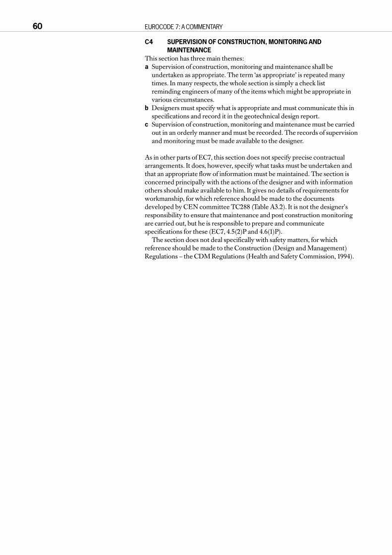
C4 SUPERVISION OF CONSTRUCTION, MONITORING ANDMAINTENANCE
This section has three main themes:a Supervision of construction, monitoring and maintenance shall be
undertaken as appropriate. The term ‘as appropriate’ is repeated manytimes. In many respects, the whole section is simply a check list reminding engineers of many of the items which might be appropriate invarious circumstances.
b Designers must specify what is appropriate and must communicate this inspecifications and record it in the geotechnical design report.
c Supervision of construction, monitoring and maintenance must be carriedout in an orderly manner and must be recorded. The records of supervisionand monitoring must be made available to the designer.
As in other parts of EC7, this section does not specify precise contractualarrangements. It does, however, specify what tasks must be undertaken andthat an appropriate flow of information must be maintained. The section isconcerned principally with the actions of the designer and with informationothers should make available to him. It gives no details of requirements forworkmanship, for which reference should be made to the documentsdeveloped by CEN committee TC288 (Table A3.2). It is not the designer’sresponsibility to ensure that maintenance and post construction monitoringare carried out, but he is responsible to prepare and communicatespecifications for these (EC7, 4.5(2)P and 4.6(1)P).
The section does not deal specifically with safety matters, for whichreference should be made to the Construction (Design and Management)Regulations – the CDM Regulations (Health and Safety Commission, 1994).
60 EUROCODE 7: A COMMENTARY

C5 FILL, DEWATERING, GROUND IMPROVEMENT ANDREINFORCEMENT
This section is effectively a check list of items which must be considered in thedesign of fills, ground improvement schemes and ground reinforcement. Ingeneral, it does not provide specific details.
C5.1 General
C5.2 Fundamental requirements
C5.3 Fill constructionThis sub-section covers selection, placement, compaction and checking offills. It provides a checklist of items which should all be covered inspecifications for earthworks.
As for natural ground, design calculations involving fill materials require theassessment of characteristic values of the material properties. At the time ofdesign, the fill to be used may not have been identified, though its propertieswill be specified. The assessment of characteristic values should follow theprinciples of 2.4.3, requiring a ‘cautious estimate’ of the properties which willbe available to prevent the occurrence of a limit state.
C5.3.1 Principles
C5.3.2 Selection of fill material
C5.3.3 Selection of fill placement and compaction procedures
C5.3.4 Checking the fill
C5.4 DewateringThe importance of control of groundwater is emphasised in 2.4.2(8)P andother places in the code. Design of dewatering is largely based on theObservational Method (EC7, 2.7). The code provides a check list of items tobe considered by designers.
C5.5 Ground improvement and reinforcementThe code provides little direction on ground improvement and groundreinforcement, and so relies on the abilities of specialist designers. It is statedin (3) that in many cases these works should be classified in GeotechnicalCategory 3. Referring to 2.1(5), it appears that the basis for this must be thatground improvement and reinforcement are not considered to be conventionaltypes of structures and foundations which could be classified under GeotechnicalCategory 2.
PART C CLAUSE-BY-CLAUSE COMMENTARY 61

C6 SPREAD FOUNDATIONSThis is the first of four sections which deal with the geotechnical design of thedifferent elements of construction.
The layout of these sections is the same in each case, consisting of:a A general statement of scope.b A list of limit states to be considered. The code encourages an orderly
approach to calculations, first listing the cases to be considered and theloads to be applied.
c Actions and design situations to be considered.d Design and construction considerations. These are mainly aspects of
construction which must be considered during the process of design.e Design for ultimate limit states.f Design for serviceability limit states.g Other items, such as ‘Foundations on rock’ in Section 6.
C6.1 GeneralSection 6 relates to spread foundations, which are usually located near to aground surface but might be used at depth, such as in a deep excavation.
C6.2 Limit statesThe list of limit states for spread foundations does not include failure byoverturning. This is considered to be a form of bearing resistance failure, inthe ultimate limit state, and to be covered by ‘excessive settlements’ in theserviceability limit state.
The list includes both combined failure in ground and in structure andstructural failure due to foundation movement. The first of these is intended torefer to situations where a failure mechanism forms in the ground and thestructure is ruptured at the same time. The second refers to situations wherethe ground itself has not failed, but displacements are sufficiently large torupture the structure. The displacements could be settlement, heave,horizontal movement or rotation, or a combination of these.
C6.3 Actions and design situations
C6.4 Design and construction considerationsC6.4(1)PThe third item in the check list relates to depth of penetration of frost. This isdealt with in BS 8004 (3.2.9.1) by the requirement that all foundations shall beplaced at depths not less than 0.45 m. The checklist requires that futureexcavations for services close to the foundation should be considered. It does notspecifically say that future excavations for other purposes should beconsidered, though this would be equally relevant. However, it does notdemand that spread foundations be designed to withstand all conceivablefuture excavations, even for services. It merely requires that the designerconsiders the situation and adopts a reasonable course of action.
C6.4(3)PThis paragraph allows spread foundations to be designed either by formallimit state calculations or by the use of presumed bearing pressures, related toserviceability limit state loads. This latter approach is essentially a‘prescriptive measure’ as defined in Clause 2.5. The section does not developthe use of presumed bearing resistance or suggest values, except for the case offoundations on rock (in 6.7 and Annex E). It emphasises the importance ofcomparable experience, as specially defined in 1.4.2(1)P. The process offinding out what has typically been done for similar structures in the sameground conditions is seen as an important aspect to geotechnical design,offered as an alternative, or better as an adjunct, to calculation.
Some suggested values of presumed bearing resistance are given in BS 8004, Tables 1 to 3.
62 EUROCODE 7: A COMMENTARY

C6.5 Ultimate limit state design
C6.5.1 Overall stabilityBesides checking the stability and serviceability of individual foundations, it isessential to check the stability of the site, or part of the site on which astructure is to be built. The reader is referred to Section 9 and to D2.2.
C6.5.2 Bearing resistance failureC6.5.2.1 GeneralThe basic requirement is represented by the inequality:Vd ≤ Rdwhere Vd is the ultimate limit state design load normal to the foundation, andRd is the design bearing resistance of the foundation against loads normal tothe foundation.
This may appear to be a trivial statement, but it has two importantimplications.a Having incorporated partial factors into both the design actions (Vd) and
design resistance (Rd), no further factor of safety is required, but merely thatRd is not less than Vd.
b The check is to be made in terms of forces normal to the foundation base.Note that the action Vd includes the weight of the foundations and of anybackfill material placed on top of them.
The code recommends that waterpressures are included explicitly in thecalculations. For drained conditions, itsuggests that water pressures aregenerally included as actions, for whicha typical situation is illustrated in FigureC6.1. It is consistent with the definitionof actions to treat drained waterpressures in this way, since they arequantities which are fixed at the start ofthe calculation (EC7, 2.4.2(1)). Thisapproach implies that resistance iscalculated in terms of effective stress.Note that the force due to pore pressureon the underside of the footing, U2, actsso as to reduce the value of Vd.
The principle of actions from a ‘single source’ noted in Table 9.2 of ENV 1991-1 is important here. Itsdevelopment for retaining structures,given in 2.4.2(17), is equally applicable tospread foundations. When designing forCase B, water pressures should bemultiplied by γG (generally 1.35, but 1.0 if favourable). However, provided theyare all treated as actions, hydrostaticwater pressures will all cancel outregardless of the factors applied. Ifpressures above the footing were treatedas actions, but those below asresistances, then an unreal imbalancewould be created by the application ofthe partial factors in Case B.
PART C CLAUSE-BY-CLAUSE COMMENTARY 63
F’1 U1 F’1 U1
S
W
U2 U2
Rd
d1
d2
d3 γ2
γ1
All design values (subscript d omitted for clarity):
Ab = area of footing base
Ac = area of column cross-section
γ1 = total unit weight of soil above water table
γ2 = total unit weight of soil below water table
S = action from superstructure
W = weight of footing
U1,U2 = forces due to water pressure
F1 = action effect of overburden
= (γ1d1+ γ2d1) (Ab- Ac)
= F’1+ U1
= (γ1d1+ (γ2 - γw) d2+ γwd2) (Ab- Ac)
where F’1 = effective action effect of overburden
U2 = γw (d2+ d3) Ab
Design value Vd = S + W + F1 - U2
= S + W + F’1 + U1 - U2
This must be matched by design resistance Rd, which in this case is an effective force.
Figure C6.1 Actions on a footing with hydrostatic water pressure

Figure C6.2 shows a situation of steadyseepage in which water pressures are fixed(and therefore are actions) but are nothydrostatic. In this situation, application ofthe factors γG = 1.35 in Case B will lead to anincrease in hydraulic gradient. However,the ‘single source’ principle would alsorequire that 1.35 be applied to the weight ofthe soil, so it is likely that the more criticalcase is γG = 1.0, with the soil/water systemacting favourably to support the footing.
Figure C6.3 shows a situation where adrained material with water pressures liesabove the footing and an undrainedmaterial beneath it. Again, the ‘singlesource’ principle will generally show that γG = 1.0 is critical.
C6.5.2.1(2)The use of buoyant weight is not recommended by the authors of thiscommentary because it tends to cause confusion. It is preferable to writecalculations in terms of total weight and explicit water pressures. Anexception occurs in the calculation of the Nγ term in the bearing capacityequation (Annex B), for which the use of buoyant unit weight of the soil ispractically unavoidable.
64 EUROCODE 7: A COMMENTARY
Figure C6.2 Footing in ground subjected to seepage
S
W
Rd
U1
Figure C6.3 Footing with hydrostatic water pressure in granular soil over undrained clay
Arrows show hydrostatic water pressures (vertical components only). Those acting on thefooting are included in Vd, whilst those alongside the footing augment Rd. In this (undrained)case, Rd is a total force acting on the base, which includes both the hydrostatic porepressures and excess pore pressures due to undrained shearing.
The action on the ground, Vd, which is to be supported by the undrained resistance Rd, isgiven by:
Vd = S + W + F′1 + U1 (all design values)
F′1 is defined in Figure C6.1.
A possible alternative approach is to include the hydr ostatic water pressures in the clay aspart of Vd, as for the drained case; these act upwards on the base of the footing, reducingthe value of Vd, as in Figure C6.1. The excess pore pressures generated at the base of thefooting due to shearing remain part of Rd, however. This is consistent with the definition ofactions in 2.4.2(1)P, since the hydrostatic component is known, but the excess porepressure is unknown, at the start (and end) of the calculation.

C6.5.2.2 Analytical methodC6.5.2.2(2)The calculation method for bearing capacity given in Annex B isrecommended for general use. This approach, using bearing capacity factors,is accepted in many countries, including Britain. It is sometimes challenged,particularly in France, on the grounds that it is not reasonable to assume aconstant value of φ′ throughout the ground at all states of stress. This relates tothe French preference for the empirical approach based on the results ofpressuremeter tests, as noted under Annex C.
Figure C6.4 shows the values of bearing capacity factors derived from theformulae of Annex B. This annex is marked as ‘informative’ and is introducedby an application rule at 6.5.2.2(2). The designer is therefore permitted to usealternative calculations, and he may need to do this for layered materials. Themethod in Annex B gives an indication of the degree of accuracy andconservatism which is appropriate. The formulae are taken from DIN 4017and are not believed to be markedly conservative. Appendix 1 compares thesevalues for Nγ with values from other similar formulae.
Some examples of the use of Annex B are presented in E2 to E4.
PART C CLAUSE-BY-CLAUSE COMMENTARY 65
a)
Angle of shearing resistance, φ (°)
Angle of shearing resistance, φ (°)
b)
20 26 34
50
45
40
35
30
25
20
15
10
5
0
Nγ
Nc
Nq
363230282422
0 15 35
1000
100
10
145302520105 40
Bea
ring
capc
ity fa
ctor
s, N
c N
q N
γ
Nc
Nq
Nγ
Bea
ring
capc
ity fa
ctor
s, N
c N
q N
γ
Figure C6.4 Bearing capacity factors derived from the formulae in Annex B

C6.5.2.2(3)P to (5)The standard formulae for bearing capacity do not easily take account of soillayering or discontinuities. These paragraphs encourage caution for suchcases, and (5) offer a simple calculation which may be very conservative insome cases.
C6.5.2.3 Semi-empirical methodSemi-empirical methods are those which rely on an established correlationbetween a test result and the ultimate bearing capacity. It is important not toextrapolate correlations beyond ‘comparable experience’ as defi ned in 1.4.2(1)P.Annex C provides an outline method for the use of pressuremeter tests.
C6.5.3 Failure by slidingC6.5.3(2)P to (3)It was noted in B2.1 that ultimate limit states may occur even when theground has not reached the limits of its strength, that is, without the formationof a complete failure mechanism in the ground. Hence it is necessary toconsider the displacement appropriate to the limit state considered. For this reason,Epd may not necessarily be the limiting passive resistance of the ground. Onthe other hand, it is likely that the shear resistance, Sd will be mobilised at itsmaximum available value with relatively little movement though it couldpossibly reduce as large movements take place. Hence it may not be possibleto obtain the maximum values of Sd and Epd simultaneously.
Passive resistance to relatively shallow bases of retaining walls may easilybe lost or much reduced by local excavations or erosion. This possibility is tobe considered. For retaining walls, a more prescriptive approach is adopted in 8.3.2.1(2).
C6.5.3(4)PErrorThe reference to Inequality (6.5) is an error. It should be (6.2).
C6.5.3(8)It should normally be assumed that the soil at an interface with concreteconstruction will be disturbed. Hence, critical state angles of shearingresistance are relevant to the interface, even if higher angles, taking advantageof the density of the soil, are used within the main body of soil. Thus thecharacteristic value of φ′k, for the interface, should be a cautious estimate ofthe critical state angle of shearing resistance. This is used to derive φ′d for theinterface and hence δd.
C6.5.3(9)PThis paragraph is mainly relevant to sliding of bases on stiff clays or weakrocks, for which undrained strength could be relevant, especially for rapidloading cases. Equation 6.4 is a standard requirement based on undrainedshear strength. The contact area is reduced in cases of eccentric loading. Therelevant value of cu is that available at the interface between the structure andthe soil. It would be preferable to refer to this as ‘adhesion’.
In some circumstances the vertical load from the foundation may beinsufficient to give a large contact area. Consider, for example, a light precast
concrete base pushed horizontally bya large force, as shown in Figure C6.5.In order to calculate the availablehorizontal resistance, the contactarea must be derived as a function ofthe vertical force and vertical bearingcapacity, with allowance for loadinclination. Mortensen (1983) hasshown that calculations of this type
66 EUROCODE 7: A COMMENTARY
Light vertical load
Large horizontal load
Figure C6.5 Light precast footing subjected to horizontal load

give a result which can besummarised as Inequality 6.5.
In some cases of rapid transientloading, for footings which fitintimately onto the ground surface,suction may ensure that no gap canform between footing and ground. Inthis case, Inequality 6.5 can bedisregarded. An example is shown inFigure C6.6.
C6.5.4 Loads with large eccentricitiesC6.5.4(1)PEC7 does not place a specific limit on the degree of eccentricity of the load ona foundation. For example, it does not have a ‘middle third rule’. This paragraphsays that special precautions are required where the resultant force lies outsidethe middle two-thirds of a footing, as illustrated in Figure C6.7. Even this maybe allowable where a relatively large footing is subject a comparatively smallvertical load, but with high eccentricity. Where the line of action of theresultant load will be close to the edge of the footing, emphasis is placed onensuring accuracy of construction and allowing a reasonable tolerance.
The authors of this commentary suggest that the middle third rule is a usefuland conservative first check, on the basis of SLS forces and material properties.However, it is not a code requirement. Examples are presented in E4 and E5.
ErrorThe combination of application rule and principle in (2) and (3)P does notmake sense.
PART C CLAUSE-BY-CLAUSE COMMENTARY 67
Light vertical load
Large horizontal load
Figure C6.6 Cast in situ footing subject to rapid transient horizontal load
L
B
B/6
B/6
L/6 L/6
R
0.6R
Figure C6.7 Definition of ‘large eccentricities’

C6.5.5 Structural failure due to foundation movementThe code recognises that an ultimate limit state may be caused in a supportedstructure by displacements in the ground, even if there is no plastic mechanismwithin the ground itself. It is diffi cult to give general advice for this situation andthe code is not very successful in providing application rules. It is important torecognise, however, that ground movements may lead to states far moreserious than normally accepted under the defi nition of serviceability limit state.
Common examples of severely damaging ground movements not causedby plastic mechanisms include:a large settlements of soft clays due to loading beyond the reconsolidation
pressure;b severe settlements of clays caused by desiccation due to tree roots;c swelling of clays due to the removal of trees or, in southern Europe, simply
due to seasonal variations in precipitation and evaporation;d settlement of loose fill due to inundation by water.
Neither the use of presumed bearing values nor the application of partialfactors can deal with heave or more complex problems. These must be treated individually.
It is conceivable that quasi-elastic settlements of the ground could causeultimate limit state failures of supported structures. However, examples of thisare hard to find.
The suggestion in Paragraph (2) is that the use of presumed bearingpressures derived from comparable, preferably local, experience may be thebest way to avoid settlement problems. The application of the boxed values ofthe partial factors probably achieves the same thing, at least for drained soil ofreasonable density and stiffness. However, for clays which are loaded rapidlyenough to remain undrained, the boxed values for cu are fairly small and maybe insufficient to prevent unacceptable settlement due to the approach ofplastic failure. For soft clays, partial factors provide no protection against limitstates due to drained settlement. This is discussed further in relation toserviceability limit states under 6.6.1 below.
It is always sensible to make an assessment of foundation settlement, eitherfrom experience or by calculation, for the worst conceivable loadings, to checkthat there is no danger of an ultimate limit state in the supported structure.
C6.6 Serviceability limit state designThe relationship of ground movement to ultimate and serviceability limitstates is discussed in B2.1. This clause, under the heading of serviceability limitstate, is equally applicable to ultimate limit states caused by groundmovement remote from shear failure. The only exception to this is 6.6(2)P,since for ultimate limit states ULS design loads must be used.
In Paragraph 8.4(2), for retaining walls, it is stated that the design methods andfactors of safety required by this code for ultimate limit state design are often sufficientto prevent the occurrence of this type of limit state (ie serviceability) provided thesoils involved are at least medium dense or firm, and adequate construction methodsand sequences are adopted. In general, the same is probably true for spreadfoundations on drained soils, if the boxed values are used for the partial factorson soil strength. This is an example of the approach discussed in 2.4.1(7)P.However, for undrained clays the boxed values are fairly small and may beinsufficient to prevent unacceptable settlement, if there is a serviceabilityrequirement for the undrained state.
The 6 paragraphs given here are relatively straightforward. The essentialfeatures to note are:a An assessment shall always be made of the vertical and horizontal
displacements. The word ‘assess’ does not necessarily imply calculation; anestimate based on appropriate experience would comply – see C1.5.2(1)P.
b Serviceability limit state design loads are to be used for this assessment. Ingeneral, these are equal to characteristic loads because the partial load
68 EUROCODE 7: A COMMENTARY
factors are unity (2.4.2(18)P). In some situations, it will be appropriate to use combination factors ψ, defined in EC1, 9.4.2, to obtain reduced valuesof the design loads. Similarly, the soil material properties are unfactored(EC7, 2.4.3(13)P).
C6.6.1 SettlementC6.6.1(2)The final two paragraphs should be read together. The assumption that a 20%increase in effective overburden stress may be considered negligible is notvalid for very soft soils, especially if this takes the cumulative effective stressover the reconsolidation pressure.
C6.6.1(6)See comments on Annex D.
C6.6.1(8)Error‘Shall’ should be ‘should’ in the first line of the final paragraph.
C6.6.2 Vibration analysisThe statements here are very basic. The reader must consult geotechnical textbooks for more information.
C6.7 Foundations on rock: additional design considerationsThe code provides basic statements on foundations on rock. Design is dependentmainly on engineering geological observation of the state of the rock with theuse of presumed bearing pressures based on comparable experience.
Following criticism, particularly from southern European countries, it islikely that the treatment of foundations on rock will be extended in futuredrafts of EC7.
C6.8 Structural design of spread foundationsAs for the geotechnical calculations, structural calculations should in principlebe carried out for all three cases A, B and C. However, in most situations it willbe obvious that the loading of Case B governs the structural design of spreadfoundations. The geometry of the foundation may well be determined byCase C, however. It is important that the structural design is then carried outfor the piece of structure which will actually be built. This implies that Case Bloading must be applied to the geometry derived from Case C, which willoften lead to larger bending moments in the footing than would result for thesmaller geometry required for Case B.
This process is exactly equivalent to the use of BS 8110 for the structuraldesign of foundations, in which the size of the foundations has beendetermined by other, geotechnical calculations. Some reduction of thebending moments might be justified by considering flexure of the foundations,but this is normally done only for rafts.
Examples are provided in E2 to E4.Eurocode 2 Part 3 contains more information about structural design of
concrete in the ground. However, this partly repeats information already inboth EC2-1 and EC7-1, and it is now considered unlikely that it will be part ofthe final Euronorm (EN) version of EC2. Some of the material in Part 3 willprobably be transferred to EC2-1.
C6.8(2)ErrorThe cross-reference to 2.1(8)P is pointless.
Eurocode 2 Part 3 contains more detailed specifications and helpfulformulae relating to linear distributions of contact pressure beneath footingsof various shape.
PART C CLAUSE-BY-CLAUSE COMMENTARY 69

C7 PILE FOUNDATIONSSee the general comments at the start of Section 6.
This section of Eurocode 7 is quite long and designers of piles will usuallyonly need to refer to parts of it. Its contents can be summarised as follows.7.1 to 7.4 Introductory;7.5 Pile load tests;7.6 Piles in compression;7.7 Piles in tension;7.8 Transversely loaded piles;7.9 Structural design of piles;7.10 Supervision of construction.
Clauses 7.1 to 7.5 will not be particularly controversial to British designers.Thus, for design of compression piles, the only clause which introducesunfamiliar requirements is 7.6.
As noted under 2.1(5), pile design in the United Kingdom is unlikely to lie inGeotechnical Category 1.
C7.1 General
C7.2 Limit statesIn this list, the term ‘overall stability’ refers to the stability of the site orbuilding as a whole, taking part of the piled structure into a general slopestability failure. It is not clear whether the term unacceptable vibrations refersto vibration due to vibratory loads on the piles in service or to vibration due topile driving.
C7.3 Actions and design situations
C7.3.1 GeneralC7.3.1(1)PSection 7 of the ENV was drafted before the text on Cases B and C wasprepared in Subclause 2.4.2. There is therefore an incompatibility betweenthese two sections. In principle, Section 7 is consistent with Case C, but notethat 2.4.3(12)P states that the partial factors for soil strength parameters givenin Section 2 are not to be used for piles. All three Cases A, B and C should bechecked, though experience will quickly show that for most commonsituations Case C always governs the geotechnical design of axially loadedpiles. (Exceptions occur for driven piles or bored, shaft controlled piles, whenthe dominant load is dead load. In this situation, using the boxed values of thepartial factors, Case B governs by a small margin. This is an unintendedanomaly which may be rectified in later versions of EC7.) Case B usuallygoverns structural design. In situations of buoyant loads or transverse loads, itmay be found that Cases A, B or C govern the geotechnical design. This isillustrated by E12.
C7.3.1(3)The need for high characteristic values in problems involving downdrag isnoted under 7.3.2.1(1)P.
When an interaction analysis is used to determine load distribution in alarge group of piles, the effect of both hard spots and soft spots should beconsidered, represented by upper and lower characteristic values of strengthand stiffness parameters. It can often be argued that the geotechnical designshould not be changed to account for these, but there may be need to considerthem in structural design. A relevant case study, but related to shallowfoundations, was presented by Simpson (1992).
70 EUROCODE 7: A COMMENTARY

C7.3.2 Actions due to ground displacementC7.3.2.1 GeneralC7.3.2.1(1)PThe treatment of downdrag and similar displacement-driven effectschallenges definitions and understanding of the term ‘action’. Reference toC2.4.2 and the clauses below is recommended.
Consideration of high characteristic values may be necessary in problemsinvolving downdrag, where it is conservative to take an upper estimate of themagnitude of the downdrag. EC7 does not give values for the partial factorsneeded to derive design values from upper bound characteristic strengths.Reciprocals of the values in Table 2.1 are sometimes used.
C7.3.2.1(2)PThe designer is allowed to chose between two approaches, treating eitherforces or displacements as the basic action. The more economic approachmay be chosen in each circumstance. An example of this is presented belowunder C7.3.2.2.
C7.3.2.2 Downdrag (negative skin friction)Downdrag will usually be analysed by calculating the maximum force whichcould be generated by negative skin friction, following Paragraph (2), andtreating this as an action (Paragraph (1)P). This implies that the force will bemultiplied by the factors for actions given in Table 2.1. Normally downdragwill be regarded as a permanent action because its ‘variation is always in thesame direction (monotonic) until the action attains a certain limit value’ (EC1,1.5.3.3). In circumstances where variable loads of short duration are alsoapplied to the pile, it may be justifiable to assume that the downdrag andvariable loads cannot occur at the same time. However, the cumulative effectof repeated loading should also be considered.
Where ground movement is treated as the action, its design value must beassessed directly in accordance with EC7, 2.4.2(19, 20). In many cases,increasing the magnitude of this movement by a factor would, in any case,have only a small effect on the force transmitted to the pile. The interactionbetween moving ground and the pile may be analysed using finite elements orother simpler approaches.
In all cases of downdrag, the characteristic value of the shaft adhesionshould be a cautious upper value. When ground movement is treated as anaction, then in Case C the characteristic shaft adhesion must be divided by afactor γm < 1. Values which are reciprocals of the strength factors in Table 2.1are suggested.
In E10, the two alternative approaches are considered on a fairly simple basis.
C7.3.2.3 HeaveC7.3.2.3(1)POnly one specific instruction is given in this subclause: the movement of theground shall generally be treated as an action. Unlike downdrag, heavemovements are almost always small enough that a study of the interactionbetween heaving ground and pile is appropriate. This could be carried out bynumerical analysis. Alternatively, a ‘balance point’ is found such that the pile ismoving up more than the ground below the balance point but less than theground above, and the whole system is in equilibrium.
This type of analysis is compared with results of a finite element analysis in E9.
PART C CLAUSE-BY-CLAUSE COMMENTARY 71

C7.3.2.3(2)EC7 has not been well developed for situations in which ground displacementis the action. In particular, no values are given for partial factors for situationswhere ground strength acts in a manner detrimental to the condition of thestructure. An analysis generally consistent with 2.4.2 can be carried out forCase B by calculating the unfactored tension in the pile and multiplying thisby 1.35 for ultimate limit state design. Lower bound values should be taken forany variable compressive forces at the head of the pile, possibly zero.
C7.3.2.4 Transverse loadingLoading of piles due to transverse ground movements is a difficult areanormally requiring specialist analysis. It could well be categorised asGeotechnical Category 3. EC7 provides general requirements of the analysis.
C7.4 Design methods and design considerations
C7.4.1 Design methodsC7.4.1(1)PThis paragraph makes it clear that all pile design calculations must be related,directly or indirectly, to the results of static load tests. Where the design isbased directly on static load tests, it must also be shown by calculations thatthe results are consistent with general experience. Pile designs may also bebased directly either on analytical calculations or on dynamic load tests;however, in these cases, the calculation methods or interpretation of thedynamic load tests must have been validated against previous static load tests.
This paragraph guards against two errors. It is recognised that a purelytheoretical calculation of pile capacity is likely to be unreliable, so calculationmethods must be related to general experience of pile load testing. On theother hand, a small number of tests, perhaps only one, on a specific site mightyield anomalous results, due either to some geological variation or poortesting technique. Thus blind reliance on tests, without backup calculation, isalso not allowed.
C7.4.1(2)Static load tests may be carried out on trial piles or working piles. Subclause7.5.2.1 strongly implies that tests on compression piles need not necessarily be taken to failure, whilst those on tension piles always should be. SinceClause 7.6 requires an assessment of the ultimate bearing resistance ofcompression piles, it will be necessary to extrapolate the results of tests nottaken to failure. The failure load should also be checked by calculation, inaccordance with 7.6.3.3.
The observed performance of an existing piled foundation may also be used as a substitute for load tests. The paragraph suggests that this isparticularly applicable to Geotechnical Category 1, where foundations simply become a copy of a design which has been successful locally. As notedin C2.1, calculations are usually not required for Geotechnical Category 1designs, but pile design will generally not lie within Geotechnical Category 1in the United Kingdom.
C7.4.2 Design considerationsThis subclause contains some important lists of items which should bechecked in the design of piles.
C7.4.2(2)PMost conventional methods of pile design are adapted to conventional ratesof testing and service loading. Only in unusual cases is it necessary to makespecific allowances for rate effects.
72 EUROCODE 7: A COMMENTARY

C7.4.2(3)PIt is reasonable that designers should consider potential changes ingroundwater regimes, but they should then decide whether to allow for themin the design. This may depend on whether their client is responsible for thechanges of groundwater regime, or whether this is the responsibility of someother party. This paragraph, however, appears to require that any potentialchanges in groundwater regime are in fact taken into account in every design.
C7.5 Pile load tests
C7.5.1 GeneralC7.5.1(1)PAs noted under 7.4.1, it is not mandatory on every project to have pile loadtests. Under some conditions, however, pile load tests are mandatory. Theseconditions are listed in this paragraph.
C7.5.1.2(2)The second grammatical paragraph in this ‘paragraph’ is rather out of place. A separate section on special situations, such as cyclic loading, would perhapsbe desirable in a future version of EC7.
C7.5.2 Static load testsC7.5.2.1 Loading procedureC7.5.2.1(1)PIt is clear from this paragraph that many pile load tests may not be taken tofailure. Only for trial piles is it required that ‘conclusions can be drawn’ about ultimate failure load. This is not really consistent with the designmethods given later (eg 7.6.3.2) which depend on ultimate resistance asmeasured in load tests. Paragraph 7.5.2.1(1)P states that the test procedureshall be such that the creep and rebound of a pile foundation can be assessedfrom the measurements on the pile. However, there is no specific mention of these items elsewhere in the chapter, except for settlement reducing pilesin 7.6.3.1(4).
C7.5.2.1(2)This paragraph breaks the CEN rules in that a reference is made to adocument which is not a CEN or ISO publication. The text will probablytherefore be changed in the final version of Eurocode 7.
The paragraph refers to the paper in the ‘ASTM Geotechnical TestingJournal’, (ASTM (1985)), ‘Axial pile loading test, suggested method’ (sic,actually ‘Axial pile loading test – Part 1: static loading’). This was written beforethe ‘Specification for piling and embedded retaining walls’ (ICE (1996)), andalso predates recent codes from other nations. Its requirements tend to beslightly less stringent than the ICE Specifi cation. It also adds some backgroundadvisory information, including comments on various national practices.
C7.5.2.2 Trial piles
C7.5.2.3 Working pilesC7.5.2.3(1)PThis paragraph could lead to difficult negotiations between client, designer,and constructor since clients will usually be very unwilling to increase thenumber of working pile load tests during construction. However, it will oftenbe possible to vary the number of working pile load tests within a presetmaximum (even if the maximum is 1 and the minimum is 0!). There could beoccasions when the designer has to inform other parties that unless thenumber of working pile tests is increased the design cannot comply with EC7.This type of situation has always existed, requiring negotiation and sometimesa strong will on the part of designers.
PART C CLAUSE-BY-CLAUSE COMMENTARY 73

74 EUROCODE 7: A COMMENTARY
4
3
2
1Lo
ad (
MN
)
M
K
C
Resistance (MN)
RM
RK
RC
Settlement
δdSδLS
δdBδdC
δLU
FB
FcFk
Curve M shows the measured load-settlement plot for a test on a single pile. By inspection,it is assessed that the shaft resistance of the pile is 2.6MN and the ultimate base resistanceis 1.6MN.
Curve K is the characteristic load-settlement plot, obtained by dividing the force on Curve Mby 1.5 (from Table 7.1). This is used without further factors for ULS Case B and for SLS design.
Curve C is derived from Curve K for ULS design to Case C. The shaft resistance is dividedby 1.3 and the base resistance by 1.6 (Table 7.2).
The applied loads are as follows (in MN):
From these design loads and the three curves, design settlements can be derived as shownon the figure: δds for serviceability loads (= characteristic in this case), and δdB and δdC for ULScases B and C.
The design requirement is then that the design settlements must not exceed the limiting valuesof the settlements, δLS for serviceability, and δLU for ultimate limit state. That is:
δdS ≤ δLS and both δdB and δdC ≤ δLU
The values set for δLS and δLU depend on the supported structure (see 2.4.6). In some cases,there may be no limit on the settlement for ULS, in which case δLU is simply “large” and theULS requirement becomes, in effect:
FB ≤ Rk and Fc ≤ RC
where and are the ultimate resistances on the characteristic and Case C curves, asshown in the figure.
Permanent
Variable
Total design loads
1.62
0.75
FB = 2.37
1.20
0.65
FC = 1.85
Characteristic ULS Case B ULS Case C
1.20
0.50
Fk = 1.70
Figure C7.1 Use of measured, characteristic and factored load-settlement curve for acompression pile
Rk Rc

C7.5.3 Dynamic load testsEurocode 7 allows design based on dynamic load tests, under the restrictedcircumstances described in (1)P. The rather cryptic requirement of (2)P isexplained in (3).
C7.5.4 Load test report
C7.6 Piles in compression
C7.6.1 Limit state designParagraph (1)P reflects the more general Clause 7.2 but selects the specificlimit states relevant to compression piles.
It is noted that an ultimate limit state might occur in a supported structuredue to displacement of the piled foundation, even if the piled foundation hasnot itself reached its ultimate capacity. Paragraph (2) states that this problemshould be addressed, when necessary, by using a factored load-settlementcurve. Figure C7.1 shows an example of how a measured load-settlementcurve could be transformed firstly to a characteristic curve, then to a designcurve for assessment of ultimate limit states.
C7.6.2 Overall stabilityC7.6.2(2)Where there is a possibility of a failure surface intersecting the piles, a soil-structure interaction analysis will probably be needed, allowing for thebending resistance of the piles helping to resist the failure.
C7.6.3 Bearing resistanceC7.6.3.1 GeneralC7.6.3.1(1)PSince the design load (or action) and design resistance already contain partialfactors, no further factor of safety is required in Inequality 7.1.
C7.6.3.1(3)PFor piles in groups, only two requirements have been recognised by the codedrafters: bearing resistance failure of piles individually and bearing resistanceblock failure. Other requirements, such as those proposed by AASHTO (1993and 1992) for overall stability and settlement have not been recognised.However, (5)P, (7)P and (8) should also be considered. Paragraph (4) makes itclear that block failure is to be analysed as a single pile of large diameter.
C7.6.3.1(4)The concept and use of ‘creep load’ is discussed in ASTM (1985).
C7.6.3.1(5)PFor ultimate bearing resistance, the only potential adverse effect of adjacentpiles is that of the group effect in (3)P and (4). It is not clear to what furthereffect this paragraph refers.
C7.6.3.1(8)The subclauses which follow deal essentially with the design of isolated piles.This paragraph makes it clear that the general procedure will require someinterpretation when multiple piles act together to support a foundation. Thestudy reported by Cooke et al (1981) is relevant here.
PART C CLAUSE-BY-CLAUSE COMMENTARY 75

C7.6.3.2 Ultimate bearing resistance from pile load testsC7.6.3.2(4)PThe basis of this paragraph is unclear. If it is considered that positive skinfriction is always developed at ultimate failure, then the pile resistancemeasured in the test should be used without correction. However, if it isconsidered that ultimate failure may be accompanied by negative skin friction,then the resistance measured in the test should be modified by subtracting anamount approaching twice the skin friction in the potentially settling layer.The latter view seems to be taken up in (5).
C7.6.3.2(6)PThe use of this paragraph is illustrated in E7.
C7.6.3.2(7)Paragraph 6(P) specifies minimum values for reduction factors ξ to be appliedto measured ultimate resistances in deriving characteristic values. Paragraph (7)discusses variability in ground condition which is known or at least suspected.It leaves some discretion with the designer in deciding whether this issufficiently accounted for by the factor ξ as specified in Table 7.1. As a simpleconservative rule, measured ultimate resistances could first be modified toallow for any known variabilities, then the factor ξ taken from Table 7.1 couldbe applied to derive characteristic values.
C7.6.3.2(8)P and (9)Usually, the load on a pile under test is only measured at the top of the pile.However, it is often possible to make a reasonable assessment of the separatecomponents of base and shaft resistance. Paragraph (9) suggests that the ratioof the base and shaft components might be derived by calculation, thoughtheir sum is based on the measured results.
The effect of an error in thisestimate is shown in Figure C7.2. Theerror in the design resistance Rd isplotted against the true ratio of shaftresistance Rs to total resistance Rt, forsituations where the ratio Rs / Rt hasbeen wrongly estimated. Even withthe estimated Rs / Rt in error by asmuch as ± 20%, the error in thedesign resistance is never more than5%, so is of little importance.
Figure C7.2 also shows the ‘error’,or difference in design resistance,obtained by using the Paragraph (11),with a single partial factor γt = 1.5. Inthis case the design resistance of thepile may be underestimated by up to13%, giving a less economic pile. Forpiles which are base-dominated (Rs / Rt small) a more economicresult may be obtained using γt = 1.5rather than γb = 1.6. This was notintended in the drafting of this clauseand it is recommended that γb = 1.6should be used in this case.
The use of Table 7.2 is illustratedfurther in E8.
76 EUROCODE 7: A COMMENTARY
Rs low Rs high γt
10
5
0
-5
-10
-150
Err
or in
Rd
(%)
0.2 0.4
True Rs/Rt
0.6 0.8 1
Figure C7.2 Effect of an inaccurate assessment of the share of resistance between shaftand base on calculated design resistance of a compression pile
Erro
r in
R d(%
)
Rs low Rs high
True Rs / Rt

C7.6.3.2(10)PTable 7.2 allows somewhat lower factors to be used for shaft resistance thanfor the bases of bored piles, but for driven piles a constant factor is used. Thesefactors refer to Case C loading and, when taken with the ξ factors in Table 7.1give overall factors in the range 1.95 to 2.4 when a single pile has been testedand the loading is entirely permanent loads. The overall factor becomes largerwhen there is a significant variable load. When several piles are tested,however, the overall factor may drop as low as 1.69 on the mean test result or1.43 on the lowest test result; higher values apply to the base components ofbored piles.
For Case B calculations, the ξ factors in Table 7.1 should be applied, but theγ factors in Table 7.2 are replaced by 1.0.
C7.6.3.2(11)Where it is not possible to distinguish base and shaft resistance, this paragraphprovides an alternative way of applying the partial factors, using γt from Table 7.2. Except for cases where shaft resistance is very much less than baseresistance, this approach will lead to a more conservative design than that ofParagraphs (8)P to (10)P. It is recommended that (11) should never be used toobtain a more economic design than would be achieved from a plausibleapplication of (8)P to (10)P.
C7.6.3.3 Ultimate bearing resistance from ground test resultsIn this approach, design shaft and base resistance are obtained fromcharacteristic shaft and base resistances by applying the same partial factors asused for the method based on load testing (Table 7.2). These factors areapplied directly to shaft and base resistances, not to fundamental soilparameters. The reason for this is that the link between measured soilparameters and best estimates of shaft and base resistance is often fairlytenuous. Hence the engineer is asked to make the best estimate of shaft andbase resistance, without any specific guidance from the code, and to divide thebest estimate value by [1.5] in order to achieve a characteristic value. Theprecise wording of this approach in (4)P should be studied.
Sample calculations are given in E2 to E4.
C7.6.3.3(4)P to (6)Although the method is based on the designer’s assessment of base and shaftresistance, usually by calculation, it is related very strongly to results of staticload tests. It is assumed that calculation rules have been derived by studyingthe results of load tests and an allowance of [1.5] is made for the likelyvariability of the test.
C7.6.3.4 Ultimate bearing resistance from pile driving formulaeSummaryPile driving formulae may be used as the basis of pile design, provided theformulae have been very thoroughly calibrated in very similar groundconditions.
C7.6.3.5 Ultimate bearing resistance from wave equation analysisSummaryWave equation analysis may be used as the basis of pile design provided that ithas been very well calibrated in very similar conditions.
PART C CLAUSE-BY-CLAUSE COMMENTARY 77

C7.6.4 Settlement of pile foundationsThis subclause requires that settlements should be ‘assessed’ (see C1.5.2 ). The assessment can probably be made from experience or from pile testresults, and should not normally require extensive analysis. It will normallyapply to the serviceability limit states, though it is noted that settlement ofpiles might cause ultimate limit states in the supported structure. In thesecases, (2)P requires that the whole load-settlement curve should be down-graded from characteristic to design values, as discussed in C7.6.1.
C7.7 Piles in tensionThe procedure for designing piles in tension is similar to that for piles incompression, except that the only design methods recognised are based onload tests or ground test results. The tensile resistance will normally bederived from the shaft resistance only. The partial factor applied will generallybe greater than that used for compression piles; the ENV (and British NAD)gives a value of 1.6 in 7.7.2.2(4)P. Designers using Clause 7.7 should first befamiliar with 7.6 for compression piles.
C7.7.1 General
C7.7.2 Ultimate tensile resistanceC7.7.2.1 General
C7.7.2.2 Ultimate tensile resistance from pile load tests
C7.7.2.3 Ultimate tensile resistance from ground test resultsNo value is given for the partial factor γm to be used in calculating tensileresistance from ground test results. Similarly, no factor ξ is specified relatingcalculations to characteristic values.
Paragraph (2)P could be taken to mean that design values for tensileresistance are to be assessed directly by the designer. However, it isrecommended that the values for ξ and γm in 7.7.2.2 should be used as a guide.The factor ξ may be taken as the ratio between best estimate tensile resistanceand characteristic value, as in 7.6.3.3(4)P.
C7.7.2.3(3)‘Annex G’ should read ‘Annex F’. This paragraph is out of place; Annex Frefers primarily to structural design of piles.
An example of the use of Annex F is given in E11.
C7.7.3 Vertical displacementC7.7.3(2)In cases where very long tension piles are used, the elastic stretching of thepiles themselves may exceed serviceability limits. It is sometimes necessary toincrease reinforcement to prevent this. In some designs mild steelreinforcement, working at relatively low stresses, is adopted for this purpose.
C7.8 Transversely loaded piles
C7.8.1 General
C7.8.2 Ultimate transverse load resistanceC7.8.2.1 GeneralC7.8.2.1(2)A standard approach, originally published by Broms, is given in Tomlinson (1994).
78 EUROCODE 7: A COMMENTARY

C7.8.2.2 Ultimate transverse load resistance from pile load test
C7.8.2.3 Ultimate transverse load resistance from ground test results and pile strength parameters
C7.8.3 Transverse displacement
C7.9 Structural design of pilesC7.9(1)PClause 2.4 requires calculations for all 3 cases A, B and C, as discussed earlierunder C7.3.1(1)P. An example is given in E12.
C7.9(2)PThe calculation method presented in Annex F shows how the design tensileforce in the pile might vary over the length, reducing towards the base of thepile. This is based on design soil strength, but makes no allowance for soilstiffness. In extreme cases, where the pile extends over most of its lengththrough highly deformable ground but reaches very stiff ground, it might benecessary to assume that the full tensile force must be carried over the wholelength of the pile. In general, this assumption might be too severe, though inpractical design it could be preferable to provide the same reinforcement overthe whole length.
C7.10 Supervision of constructionThe requirements of this clause are generally consistent with ‘Specification forpiling and embedded retaining walls’ (ICE (1996)).
C7.10(5)PThe requirement that records be kept for at least 5 years is not included in theICE Specification, but the CDM Regulations (Health and Safety Commission(1994)) implicitly require that as-built drawings are retained throughout thelife of the structure. These will normally contain a summary of the datarecorded during construction, including ground stratification.
PART C CLAUSE-BY-CLAUSE COMMENTARY 79

C8 RETAINING STRUCTURESSummaryThis section considers the design of all types of earth retaining structures, andincludes a clause on anchorages. It relies on Sections 6 and 7 for thefoundations of the structures (EC7, 8.2(4)) and on Section 9 for requirementsof overall stability.
The section has some similarities with BS 8002, but also some differences.Appendix 3 lists the main items required for retaining wall calculations,comparing BS 8002 and Eurocode 7. In particular, Eurocode 7 mentions‘unplanned overdig’ (8.3.2.1), but its requirements are slightly different fromthose of BS 8002 and they are applied only to ultimate limit state calculations.Eurocode 7 does not have a minimum surcharge to be applied to the retained ground.
Eurocode 7 applies partial safety factors, taken from Section 2, for ultimatelimit state design but uses unit factors for serviceability limit states. Thiscontrasts strongly with the approach of BS 8002. However, both codes pointout that for structural design, even at ultimate limit state, it may be necessaryto consider earth pressures greater than limiting active values where thesupported soil is overconsolidated or compacted and the structure is fairly rigid.
See general comments at the start of Section C6.
C8.1 GeneralC8.1(1)PStructures which retain water are included in this clause with regard to theirstrength and stability, but watertight design is not included.
C8.2 Limit statesC8.2(1)PThe final 3 items in the check list do not refer directly to the strength orstability of the wall. However, if flow of water or transport of soil particles isallowed to develop, instability and damage may ensue.
C8.2(4)The bases of gravity walls are spread foundations, often subject to markedlyeccentric loading. It was noted in C6.2 that no specific calculation is requiredfor ‘overturning’ since this is regarded as a form of bearing capacity failure.The particular requirements of 6.5.4 for highly eccentric loading areimportant, however. See C6.5.4(1).
C8.3 Actions, geometrical data and design situations
C8.3.1 ActionsBesides listing relevant actions, 2.4.2 also requires the use of Cases A, B and Cand the partial load factors to be applied. These are to be applied to retainingstructures, with the special note in 2.4.2(17) about the application of Case B.The clauses of Section 8 refer directly to ‘design values’ rather thancharacteristic values. These design values should generally be derived fromcharacteristic values in accordance with 2.4.2.
C8.3.1.1 Weight of backfi ll material
C8.3.1.2 SurchargesUnlike BS 8002, Eurocode 7 does not impose a minimum design surcharge.The authors recommend that designers make their own assessment of thecharacteristic surcharge. In some cases, especially where the retaining wallsare small, the surcharge may be appreciably less than the rather severe valuerequired by BS 8002.
80 EUROCODE 7: A COMMENTARY

C8.3.1.3 Weight of water
C8.3.1.4 Wave forces
C8.3.1.5 Supporting forcesFor the purpose of checking the stability of a retaining wall, the force in adead-man anchor will generally be a result of the wall-ground interaction andso it is not an action, in that calculation. However, a prestressed anchor could,in principle, have a prestress force which is chosen by the designer, togetherwith an additional component which results from the wall-groundinteraction. In this case, for the purpose of the stability check, the prestress isan action, and the additional component is a reaction, not an action. Inpractice, many prestressing systems are fairly extensible, so the ‘reaction’component is small compared with the prestress.
It was noted in C2.4.2 that the same force may be a reaction in somecalculations and an action in others. For prestressed anchors, for example, the‘reaction’ to wall-ground interaction, could be regarded as an action for thepurpose of the structural design of the wall. In this case it might be eitherpermanent or, if dependent on other variable loading such as traffic or tides, itcould be variable.
EC2, Table 2.2 gives values for partial factors on prestress actions inprestressed concrete, but separate values for ground anchors are not providedin the Eurocode system.
The sequence of evaluation of the various forces involved in design ofground anchors is discussed in C8.8.2.
C8.3.1.6 Collision forces
C8.3.1.7 Temperature effectsC8.3.1.7(2)The effect of temperature on prop loads has been considered in the recentCIRIA report ‘Prop loads: guidance on design’ (Twine and Roscoe (1997)).
C8.3.2 Geometrical dataIn most cases, small variations in geometrical data are considered to beaccommodated by the safety elements, mainly partial factors, included in thecalculations (C2.4.5). However, because the design of retaining walls isextremely sensitive to ground levels and water levels, special requirements areincluded in this subclause. (In 6.5.4, a similar exception was made for loadswith large eccentricities, for which a direct allowance for constructiontolerance of a spread foundation was required.)
C8.3.2.1 Ground surfacesC8.3.2.1(2)This paragraph requires that the ground level of passive soil should beassumed to be slightly lower than the lowest the designer expects to occur.This is not intended to give the designer or constructor permission to over-excavate in front of the wall. Rather, it is an allowance for the unforeseenactivities of nature or humans who have no technical appreciation of thestability requirements of the wall.
The requirements of EC7 are similar to those of BS 8002, but not identical.BS 8002 requires a minimum allowance of 0.5 m, whereas Eurocode 7 sets 0.5 m as a maximum. This paragraph is an application rule, and so It ispermissible to use alternative rules different from the application rules given in thisEurocode, provided it is shown that the alternative rules accord with the relevantprinciples (1.3(5)P). In 8.3.2.1, (2) is an application rule of the principle (1)P, sosome discretion is left with the designer. An alternative wording of thisparagraph has been proposed by Krebs Ovesen and Simpson as follows (themain changes being shown in bold type):
PART C CLAUSE-BY-CLAUSE COMMENTARY 81

In ultimate limit state calculations in which the stability of a retaining wall dependson the passive resistance of the ground in front of the structure, the ground level of thepassive soil should be lowered below the nominal, expected level by an amount ∆a.The value of ∆a should be selected taking account of the degree of control to beexerted on site over the level of the surface. For situations with a normal degreeof control, the following should be applied:a for a cantilever wall, ∆a should equal [10%] of its height, limited to a maximum
of [0.5] m.b for a supported wall, ∆a should equal [10%] of the height beneath the lowest
support, limited to a maximum of [0.5] m.
Smaller values of ∆a, including zero, may be used where the surface level is to becontrolled reliably throughout the period in which it is operational.
Larger values of ∆a should be used where the surface level is particularlyuncertain.
It is recommended that thisground level reduction should onlybe disregarded with great caution,particularly where embedded wallsrely heavily on relatively shortpenetrations into the restraining soil.Using the EC7 boxed values for soilstrength factors, Simpson (1994)showed that for small penetrationsthe effect of this allowance was togive an equivalent factor of safety onpassive pressure exceeding 2,whereas it drops to about 1.5 withoutthis allowance. This is illustrated inFigure C8.1. Hence, if the groundlevel allowance is disregarded, thevalues of partial factors to be used inthe calculations may need amendment.
The original purpose of thisallowance was described by Simpson(1992). Embedded walls which haveonly small penetrations into soilswith high shear strength (or highangles of shearing resistance) arevery sensitive to any reduction in theground level in front of the wall.Figure C8.2 compares twoexcavations in dense sand or gravel(φk′ = 40°). In excavation (a), the wallwould be at failure (for φk′) with apenetration of 1.25 m, but with apenetration of 2.0 m it would havereasonable factors of safety of 1.2 ontanφ′ or 2.0 on passive pressure (notethat EC7 requires 1.25 on tanφ′).However, excavation (b) shows thatif the excavation is taken only 0.5 mdeeper by any accidental or naturalprocess, the wall again reacheslimiting stability. The dramatic effectof this small ‘overdig’ has led thedrafters of both EC7 and BS 8002 torequire that a direct allowance ismade for it.
82 EUROCODE 7: A COMMENTARY
Depth (m)
0 1 32
4
3.5
3
2.5
2
1.5
1
0.5
0
Equ
ival
ent f
acto
r on
Kp
γφ
= 1.25
φ' = 35°
φ' = 25°
4 5 6 7 8 9 10
Figure C8.1 Overall factor of safety on Kp derived from boxed values with overdig allowance(after Simpson (1994))
φ’= 40°-8.5m-8m-8m
0mA B C D
Wall penetration (m):Factor of safety:
1.251
1.51
2.6Fφ = 1.2
2.0Fp = 2
Fφ = 1.2φ’mob = 35°
Figure C8.2 Effect of overdig on factor of safety of a wall with small penetration into densegranular material (after Simpson (1992))
(a) (b)

Terzaghi (1954) recommended a specific allowance for ‘overdig’: the depthof penetration of sheet pile walls was to be increased by 20% to allow for ‘theeffects of unintentional excess dredging, unanticipated local scour, and thepresence of pockets of exceptionally weak material’.
Figure C8.3 shows a simplecantilever retaining wall reproducedfrom CIRIA Report 104 example B2,which is considered in some detail inE14. Some results for this wall,calculated using simple active andpassive pressures, are shown in Table C8.1. It has been assumed thatthe ‘moderately conservative’parameters of CIRIA 104 areequivalent to EC7’s ‘characteristic’values. In Columns 1 and 2,Eurocode 7 Case C designs arecompared with and without overdigof 0.4 m, 10% of the retained height.It can be seen that the effect ofoverdig is to increase the length ofthe wall by about 20%, but, moreimportantly to increase the bending
moment in the wall by about 60%. For comparison, CIRIA Report 104requires that the bending movement is calculated initially using unit factors ofsafety, for which Columns 3 and 4 show that the effect of overdig is to increasewall length by 20% and bending moment by 70%. These results make it veryclear that a fairly modest reduction in the level of the passive material requiresa very much stronger wall of somewhat greater length. The requirements ofEurocode 7 for unplanned overdig should therefore be set aside only inexceptional circumstances and with great caution.
Table C8.1 The importance of ‘overdig’Case EC7 EC7 CIRIA CIRIA
Case C Case C F = 1 F = 1overdig no overdig overdigColumn 1 Column 2 Column 3 Column 4
γφ = Fs 1.25 1.25 1.0 1.0φ′d 20.5° 20.5° 25° 25°Overdig (m) 0.4 0 0.4 0Length (m) 14.42 12.28 11.95 10.0BM (kNm/m) 808 507 511 303
(= 303 × 1.7)
BM factor 1.0 1.0 1.5 ?? 1.5ULS BM (kNm/m) 808 507 767 ?? 455
C8.3.2.2 Water levelsInformation on design water levels and water pressures relevant to retainingwall design is dispersed throughout the code. Water levels (a geometricalparameter) are considered here and in 2.4.2(11), whereas water pressures areconsidered in 2.4.2(8)P to 2.4.2(10)P and in 8.5.6. The effect of drainage isconsidered in 8.4(5)P and (6)P. Paragraph 2.4.2(10)P makes it clear that adistinction can be made in the severity of assumptions used for ultimate andserviceability limit states. Subclause 8.5.6 considers water pressures from thepoint of view of practical soil mechanics. A practical example of normal andextreme water levels, not related to retaining walls, is presented in E12.
PART C CLAUSE-BY-CLAUSE COMMENTARY 83
1m
1m
h = 4m
γ = 20 kN/m3
γ = 10 kN/m3
φ’= 25° (moderatelyconservative)
Figure C8.3 Cantilever wall example (CIRIA Report 104, Example B2)

C8.3.3 Design situationsC8.3.3(1)PThe effect of future structures and surcharge loadings is to be ‘considered’ inthe design. However, the extent to which they should be accommodated bydesigns will depend on the legal and contractual situation.
C8.4 Design and construction considerationsC8.4(1)PErrorThe cross reference to 2.1 is thought to be incorrect. It should probably be 2.4.1.
C8.5 Determination of earth and water pressures
C8.5.1 Design earth pressuresMany of the subclauses in this clause refer to states of earth pressure which arenot at limiting active or passive values. These are generally not used in sizingthe geometry of retaining structures. However, they are relevant toassessment of ground movement, generally serviceability limit states, and tostructural design for both ultimate and serviceability limit states.
C8.5.1(4)The parameter values referred to here are all design values, factored accordingto Table 2.1.
This paragraph allows the ratio δ / φ′ to be set to 1.0 for concrete castagainst the ground, provided that the design critical state angle of shearingresistance is used for φ′. However, it also notes that the vertical equilibrium ofthe wall and the direction of vertical movements of the wall and groundshould be considered. In many situations, this makes it impossible for δ / φ′ toequal 1.0 in all the soil on both sides of the wall. If a lower value is adopted,such as 2/3, it is much more likely that equilibrium can be achieved. It maytherefore be wise to use 2/3 unless vertical equilibrium and displacements arechecked very rigorously.
The paragraph discusses k = δ / φ′ for sand and gravel, but not for clay in adrained state. However, its recommendations could probably be applied inthis case. A more detailed discussion is provided by BS 8002 (2.2.8).
Figure 8.4 of the code illustrates the type of situation in which verticalequilibrium is most important to selection of δ / φ′. The wall is being requiredto support vertical loads and to transfer these into the ground in friction. Thismay involve wall friction in a direction which is adverse for the calculation ofactive pressure; that is it causes an increase in the active pressure. Calculationsfor the horizontal earth pressures and vertical load capacity of the wall mustuse consistent values and directions for wall friction.
No mention is made here of the angle of friction across the ‘virtual back’ of agravity retaining wall. For walls with significant heels, it is usually assumedthat the force crossing the virtual back is parallel to the ground surface; that is,there is no friction across the virtual back if the ground surface is horizontal.An example is presented in E13.
The term ‘precast concrete’ is misused here. It should be taken to includeany form of concrete not cast directly against the soil.
C8.5.2 At-rest values of earth pressureC8.5.2(2)Several formulae of the type given in Equation 8.1 are discussed by Simpson et al (1979). These formulae are thought to be reasonably accurate for over-consolidation ratios up to about 10.
84 EUROCODE 7: A COMMENTARY
C8.5.3 Limit values of earth pressureC8.5.3(1)PThe graphs in Annex G are copied from CIRIA Report 104 and are based onCaquot, Kerisel and Absi (1973). Larger scale versions of these graphs, basedon Kerisel and Absi (1990) may be found in BS 8002. Annex G also givesequations for coefficients of active and passive pressure based on plasticitysolutions. These equations are quite complex, but are suitable for use incomputer programs.
C8.5.3(2)PThe most common item in which use of simple active and passive earthpressures may be unconservative is the calculation of strut loads. For thisreason, CIRIA Report 104, which uses simple active and passive earthpressures, advises a factor of safety of 2 on calculated strut loads. Eurocode 7does not apply a factor in this way, but requires in this paragraph that theeffect on the distribution of earth pressure of kinematic constraints such asstruts should be considered. This may be done in several ways:a by rules of thumb (eg Terzaghi and Peck (1967) or EAU (1980));b from field observations (eg Twine & Roscoe (1997)); orc by numerical analysis. This could involve finite element or other software
which takes account of pressure redistribution, such as FREW, SPOOKS,WALLAP etc.
See also C8.6.1(6)P.
C8.5.3(3)PThis paragraph should be read together with 8.5.1(4).
C8.5.4 Intermediate values of earth pressure
C8.5.5 Compaction effectsEarth pressures caused by compaction are not normally considered whensizing the geometry of a wall, but they may affect the structural design. Amethod for calculating earth pressures was published by Ingold (1979).
C8.5.6 Water pressuresSee earlier comments on 8.3.2.2.
Eurocode 7 does not have a minimum wall pressure, such as the ‘30z’ rule ofCP2 (‘5z’ in kPa). Instead, it requires a careful review of the water pressureswhich could occur in a range of circumstances. In this respect, Eurocode 7 issimilar to BS 8002.
C8.6 Ultimate limit state designThis clause covers ultimate limit states of failure in the ground, which usuallydetermine the geometry of retaining walls, and ultimate limit states ofstructural failure. Generally, the requirements of ultimate limit state designwill form the basis of most of the calculations required.
C8.6.1 GeneralC8.6.1(4)PThis paragraph cross-refers to 2.1(8)P and (9). Compatibility of deformationsis particularly important where there are brittle materials or structuralmembers. These could include light sheet pile sections, subject to localbuckling, struts which may buckle, and many forms of connections betweenstruts, ties and wall. If large movements are needed to release high in situearth pressures, reinforced concrete sections could become damaged andsuffer a reduction of strength.
PART C CLAUSE-BY-CLAUSE COMMENTARY 85

In other cases, where there is no brittle behaviour involved, there is no limitto the displacement allowed in ULS calculations. The only requirement isthat equilibrium is attained. Design calculations should, however, alsoconsider that large displacements may cause a ULS in an adjacent structure.
C8.6.1(6)PIt is important to consider redistribution of earth pressure, both as a means ofreducing calculated bending moments, and critically to avoid under-estimation of strut loads. If allowance is not made for redistribution, therequirement of CIRIA Report 104 becomes relevant and a large factor isapplied to calculated strut loads, ie 2.0. See also C8.5.3(2)P.
C8.6.2 Overall stability
C8.6.3 Foundation failure of gravity wallsAn example of the design of a gravity wall is given in E13.
C8.6.4 Rotational failure of embedded wallsExamples of the design of embedded walls are given in E14 and E15.
C8.6.5 Vertical failure of embedded wallsC8.6.5(3)PUsually prestressing forces are well controlled and unlikely to increase afterconstruction, unless free anchor lengths are very short (note 8.8.2(7)).Individual tendons may temporarily have high forces during stressing, but it isunlikely that the forces averaged over a reasonable number of anchors willsignificantly exceed the intended value. Paragraph 8.3.1.5(1)P points out thatforces caused by prestressing operations are regarded as actions. In calculations,the factors on actions taken from Table 2.1 should therefore be applied.
C8.6.5(4)P, (5), (6)PSee C8.5.1(4).
C8.6.6 Structural design of retaining structuresParagraph 8.5.1(6) points out that the earth pressures relevant to ultimate andserviceability limit state may be fundamentally different. From the point ofview of practical structural design, it is generally necessary that the loads onstructural elements for ultimate limit state calculations are greater than thosefor serviceability limit state. It is therefore recommended that the structuraldesign should be checked for pressures in the retained soil obtained byfactoring the serviceability limit state earth pressures (see comments on 8.7.4).This recommendation effectively means that Case B is replaced by arequirement that the permanent load factor [1.35] is applied to serviceabilityearth pressures, even if these are greater than the characteristic values oflimiting earth pressures used in the Case C ultimate limit state design check.The note in 2.4.2(17) on application of Case B still applies.
Note that this subclause refers only to ultimate limit state design of structures.
C8.6.6(3)PThis paragraph repeats the important sentiment of 2.1(9) and 8.6.1(4)P.
C8.6.6(4)EC3-5 categorises steel sheet pile sections, showing which are sufficientlyrobust to allow development of plastic hinges, and which would buckle beforethis becomes possible. See also C8.6.1(4)P.
The possible use of a model factor γSd is mentioned in 2.4.2(15). NeitherEurocode 7 nor the British NAD give values for this factor, and a value of 1.0has been adopted in almost all trial calculations known to the authors.Possible future developments are noted in D2.2.
86 EUROCODE 7: A COMMENTARY

C8.6.6(5)PErrorThis Paragraph is a repeat of (3)P and should be deleted.
C8.6.7 Failure by pull-out of anchorsThis subclause gives basic requirements. More details of calculation methodscan be found in BS 8081. See also C8.8.
C8.7 Serviceability limit state
C8.7.1 General
C8.7.2 DisplacementsThe intention of this subclause is to require careful consideration of likelydisplacements without demanding unnecessary calculation or encouragingdubious attempts at calculation which might be misleading. Figure C8.4shows a flow chart for the decisions required.
The draft of Eurocode 3 Part 5(prENV 1993-5:1997) containsadditional information onassessment of ground movements,particularly for sheet pile walls.
C8.7.2(1)PErrorThe cross-reference to 2.4.5 shouldbe 2.4.6.
C8.7.3 Vibrations
C8.7.4 Structural serviceability limit states
This is an important subclause,particularly if the comments inC8.6.6 are applied. However, EC7gives little detail. The user is requiredto find characteristic values ofstiffnesses both for the ground andfor structural elements. For structuralelements, EC1, 5(2) specifies that thecharacteristic values of stiffnessparameters should be mean values.This is accepted for structuralstiffnesses but is over-ridden in EC7for ground stiffness by 2.4.3(5)P,which is applied to all soil and rockparameters, not only strength. This isdiscussed further in B4.12.
Because it is difficult to quantifystiffness and to perform soil-structure interaction calculations, 1/2 (Ka + Ko) is sometimes adopted asthe earth pressure coefficient forstructural serviceability design ofconcrete gravity walls. The value ofKo should be derived as in 8.5.2(2).
PART C CLAUSE-BY-CLAUSE COMMENTARY 87
(5) Do the specialconditions of
(4) apply?
(1) Establish limiting valuesfor allowable displacements.
NO
(2) Cautious assessment of distortion and displacement based on
comparable experience.
(3 ) Does thecautious assessment in (2) exceed
the limiting values in (1)?
(4) Does the cautiousassessment in (2) exceed 50%
of the limiting values in (1)?
No further analysis isrequired by the code.
The design isfairly critical,
but might be justifiedby detailedanalysis of
displacements in accordance with
(5) and (6).
NO
NO YES
YES
YES
Figure C8.4 Flow chart for serviceability limit state displacements (Subclause 8.7.2)

Table C8.2 Use of partial factors in anchor design and useSource of action or force ⇒ ⇒ ⇒ ⇒ ⇒ ⇒ ⇒ Magnitude of force ⇒ ⇒ ⇒ ⇒ ⇒ ⇒
From wall analysis [a]
SLS design force ♦Case B ULS design force ↓ ♦Case C ULS design force ↓ ♦ULS design force (greater of ↓ ♦
cases B and C) ↓ ↓For anchor design and ↓ ↓
assessment testing ↓ ↓Required minimum ULS design ↓ ♦
resistance ↓ ↓Required minimum characteristic ↓ l x 1.5 [b]♦
resistance ↓ ↓ ↓Second check on characteristic ● ↓ ↓
resistance ↓ ↓Required minimum assessment ↓ l ♦ (x 1.1) [c]
test result ↓ ↓Required minimum mean ↓ l x 1.3 [c] ♦
assessment test result ↓ ↓Selected maximum assessment test ↓ l ? [d] ♦
load (> required mean test result) ↓ ↓For anchor use ↓ ↓
Typical preload in acceptance test l x 1.5 [e]♦ ↓Typical lock-off load l ♦ (x 1.1) [f] ↓Greater of these two ↓ ♦ ↓
Design of wall structure [g] ↓ ↓ ↓– anchors subject to ↓ ↓ ↓
acceptance tests only ↓ ↓ ↓Characteristic action for structural ↓ ♦ ↓
design ↓ ↓ULS design action – short term ↓ l x 1.0 to1.5 [h]♦ ↓
Design of wall structure [g] ↓ ↓– anchors subject to ↓ ↓
acceptance tests ↓ ↓Characteristic action for structural ↓ ♦
design ↓ ↓ULS design action – short term ↓ l x 1.0 to1.5 [h]♦
Design of wall structure [g] ↓– long term working state ↓Characteristic action for structural ♦
design ↓ULS design action – long term l x 1.35 [i]♦Check for major increase in load with l ?→?→?→?→♦
time
♦ Value of anchor force at indicated stage in the process
[a] SLS force may exceed ULS force in some cases. Case A should be treated as Cases B and C, when relevant
[b] For permanent anchors (EC7, 8.8.5(6)). Use 1.25 for temporary anchors
[c] EC7 Table 8.1, assuming more than 2 assessment tests
[d] Designer’s or constructor’s judgement, in order to achieve required mean result
[e] See BS 8081, 11.4.3. Use 1.25 for temporary anchors
[f] See BS 8081, 11.4.3
[g] Including bearing plates, walings and connections. prEN 1537:1996 contains information relevant to design of tendons
[h] EC1, Table 9.2 for variable actions. Reduced factors may be considered for short duration loading
[i] EC1, Table 9.2 for permanent actions
88 EUROCODE 7: A COMMENTARY

C8.8 AnchoragesThis clause on anchorages is quite short and for British use should besupplemented by reference to BS 8081. Anchorages are to be designed foractions based on 2.4.2 and the earlier clauses of Section 8.
The approach taken to geotechnical design of ground anchorages is basedentirely on load testing. Calculations of appropriate sizes, shapes, groutpressures etc. are not mentioned and are seen merely as tools used in theprocess of selecting an anchor for testing. For structural design of theanchorages, the user is directed to Eurocode 3 (EC7, 8.8.2(6)P).
Construction of ground anchorages is the topic of prEN 1537 ‘Groundanchors’. This also gives advice on the preliminary design of anchorages. Inthe terms of EC7, such preliminary design is the sizing of an anchor to beconstructed for test purposes.
C8.8.1 GeneralThe code says that this subclause refers to any type of anchorage, including soilnails, dead-man anchors, as well as pre-stressed anchors. However, most ofthe text is only relevant to pre-stressed anchorages. Dead-man anchors canbe designed according to Section 8 as a whole, considering Clause 8.8 onlywhere relevant.
C8.8.2 Anchorage designTypically, calculations for a retaining wall or other type of structure will havebeen carried out at ultimate limit state, for Cases B and C, and A if relevant.From each of these, a required minimum capacity will have been calculatedfor the anchors. It is necessary to derive from these the target values forassessment and acceptance tests, together with an appropriate lock-off forcefor the anchors and design forces for structural elements such as tendons andwalings. EC7 does not state clearly how these values are to be derived.
Table C8.2 illustrates the process involved in anchor design, from theanalysis of the retaining wall to design of structural members. Approximaterelative values of the forces and actions are indicated by a ♦ symbol.
It is recommended in this commentary that the minimum required anchorcapacity, derived from wall or other calculations, should be treated as theminimum ULS design resistance of the anchors. This design resistance mustequal the characteristic resistance divided by the factor γm (Equation 8.4). Thisleads to a minimum value for the characteristic resistance.
Calculations may also be performed for the serviceability limit state,yielding another minimum required resistance; the characteristic resistance ofthe anchors should also be not less than this value.
This approach to anchorage design differs from pile design in Section 7, inwhich piles are designed for Case B (factored loads, unfactored soil orunfactored load tests – γm = 1) and for Case C (unfactored (permanent) loads,factored soil or factored load tests). However, it is proposed here that anchorsare designed for Case B and/or C, which effectively give factored anchorloads, together with factored load tests. The anchor loads derived from Case Bor C are treated as required design anchor capacities.
It is considered that this approach generally leads to anchor designs similarto conventional practice, though possibly more conservative in some cases.An alternative might be to consider the required capacities derived from ULSwall calculations to be the required characteristic resistances of the anchors.This would be similar to the approach taken to pile design, but would beunconservative compared with conventional anchor design.
Assessment tests on anchors will normally prove the capacity of thegrout/ground interface but will not fail the tendon/grout interface or thetendons themselves. Hence separate partial factors are quoted for thetendon/grout interface and the tendons themselves.
A worked example is presented in E16.
PART C CLAUSE-BY-CLAUSE COMMENTARY 89

C8.8.3 Construction considerationsThis subclause gives only a very bare outline of the specification needed forcorrosion protection. Both BS 8081 and prEN 1537, Section 6 give guidanceon corrosion protection for temporary and permanent anchors.
C8.8.4 Anchorage testing
C8.8.5 Assessment testsC8.8.5(4)PIn prEN 1537:1996 ‘Ground Anchors’, the creep limit is defined as themaximum creep displacement rate permitted at a specific load level. The creepdisplacement rate (ks) is defined as:ks = (s2 – s1) / log10 (t2 / t1) (note that ks has units of displacement)where si = displacement at time ti.
For ULS the creep limit load is defined as the load at which ks is equal to 2 mm. prEN 1537 states that the limit of 2 mm will be used as one of the ULSfailure criteria in an assessment (on-site suitability) test. The creep limit rateshould not exceed 1 mm at proof load where investigation tests have beencarried out (or 0.8 mm where no investigation tests have been carried out).
The measurement of the creep displacement rate may be carried out usinga maintained load test, as defined in prEN 1537 which recommends timeintervals for measurement of anchor head displacement of 1, 2, 3, 5, 10, 15, 20,30, 45, 60 minutes. For fine grained soils, longer time intervals may be needed.
C8.8.6 Acceptance tests
C8.8.7 Supervision of construction and monitoringCommentA subclause should be added requiring that records be kept of groundconditions encountered.
90 EUROCODE 7: A COMMENTARY

C9 EMBANKMENTS AND SLOPESThis section covers two main topics: site stability (including slopes) andembankments. It might have been better to place a section on site stability atan earlier point in the code, since reference is made to this section fromSections 6, 7 and 8. In principle, embankments and slopes should be designedfor Cases A, B and C, as with other items. However, Case B is rarely found tobe critical, and 9.5.1(5)P states that Case A ... may generally be omitted. Thesection is therefore directed almost entirely to Case C. The partial factor ontanφ′ in Table 2.1 could be the only factor of safety against failure in many ofthe situations relevant to this section. The value of 1.25 is somewhat less thanconventionally used for major slope stability checks. For example, BS 6031requires an equivalent overall factor of safety of between 1.3 and 1.4.However, noting that higher partial factors are applied to c′ and cu it isconsidered that the factors in Table 2.1 are adequate provided that thecharacteristic soil strengths are ‘cautious estimates’ (2.4.3(5)P).
C9.1 ScopeC9.1(1)PIt is strange that dykes and dams are excluded from Section 9, though they arenot excluded in 1.1. It is recommended that dykes and dams should not bedesigned to ENV 1997-1:1995.
C9.2 Limit statesC9.2(1)PNote that deformations in the ground may cause either ‘structural damage’(ultimate limit states in the structure) or ‘loss of serviceability’ (serviceability limit states). In principle this is correct, but it is difficult to make a clear distinction in practice. Hence Paragraphs 9.5.2(1)P and 9.6(1)Pare almost identical.
C9.3 Actions and design situationsC9.3(2)PThe list should also include the effects of vegetation, both in strengtheningslopes and in causing desiccation which may lead to water-filled cracks.
C9.3(3)PIt is stated that the failure of drains, filters and seals shall be considered. Thisdoes not necessarily mean that the design must accommodate failure,provided that failure can be shown to be avoidable or sufficiently unlikely. Forultimate limit states, this means that it must be made extremely unlikely. Theprinciples developed under 8.3.2.2 and 8.4(5)P and (6) also apply here.
C9.4 Design and construction considerations
C9.5 Ultimate limit state design
C9.5.1 Loss of overall stabilityC9.5.1(3)PAs noted at the start of this section, it will usually be obvious by inspectionthat Case C is critical, and calculations for Cases A and B should not benecessary. (See also 9.5.1(5)P.) This conclusion assumes that the weight of theground is treated as a ‘single source’, as discussed in 2.4.2(17). The statementin 2.4.2 appears to be restricted to retaining walls, but could also be appliedhere. This is clarified by 9.5.1(6).
PART C CLAUSE-BY-CLAUSE COMMENTARY 91

C9.5.1(4)The implication of this application rule is that the following methods of slopestability are acceptable:a Bishop (1955) methods with either horizontal or inclined interslice forces;b Janbu (1957) with inclined interslice forces;c Morgernstern and Price (1965);d the method of Spencer (1967).
The following methods are not acceptable:e Fellenius (1927), also known as the Swedish circle method;f Janbu (1957) with horizontal interslice forces.
C9.5.2 DeformationsC9.5.2(1)PThis paragraph, still under the heading ultimate limit state design, refers tocases where deformation may cause ultimate limit states in supportedstructures. Compare 9.6(1)P for serviceability limit states.
C9.5.2(3)The main method available for limiting the deformation of a slope is bylimiting the mobilised shear strength. Where slopes support structures whichare very sensitive to movement, it might be necessary to use partial factorsapplied to shear strength which are slightly higher than those given in Table2.1. See the note at the start of this section.
C9.5.3 Superficial erosion, internal erosion and hydraulic uplift
C9.5.4 Rock slides
C9.5.5 Rock falls
C9.5.6 Creep
C9.6 Serviceability limit state design
C9.7 Monitoring
92 EUROCODE 7: A COMMENTARY

ANNEX AChecklist for construction supervision and performance monitoring
Annex A supplements Section 4.
PART C CLAUSE-BY-CLAUSE COMMENTARY 93

ANNEX BA sample analytical method for bearing resistance calculation
The calculation method for bearing capacity given in Annex B isrecommended for general use. It is a development of the original work ofBrinch Hansen (1970), taking advantage of more recent work, particularly thatof Smoltczyk and his co-workers in Stuttgart. This has led to a revision of theformula for Nγ, providing a less conservative value. A comparison of variousformulae for Nγ derived by different researchers over the past decades ispresented in Appendix 1. Formulae for Nc and Nq are well established.
The values of bearing capacity factors implied by the equations given inAnnex B are shown graphically in Figure C6.4.
Formulae for depth correction factors, d, have been omitted from Annex Bbecause they are regarded as unreliable. Although they have the potentialadvantage of providing continuity between the design of a footing and that ofa pile, their practical relevance is minor and they can be neglected, withoutundue conservatism, in the design of spread foundations.
Some examples of the use of Annex B are presented in E2 to E4.Traditional design uses an overall
factor of safety on bearing capacity inthe range 2 to 3 (BS 8004, 2.2.2.3.3.4notes this range, but only for‘cohesive’ soils). Figure CB.1 showsthe overall factors on bearingcapacity in drained soils derived fromthe equations in Annex B, togetherwith the boxed values of partialfactors (EC7, Table 2.1), also adoptedin the British NAD (Table 1). Theboxed values imply overall factors inthe range 2 to 2.5 for foundationsdependent mainly on Nc (ie‘cohesion’) or Nγ. Where bearingcapacity is strongly dependent on thebenefit of overburden pressure abovethe foundation depth, Nq becomesimportant. In this case, the overallfactor of safety could fall below 2.
For undrained soils, EC7 and the British NAD lead to an overall factor ofsafety of only 1.4 (ie the factor on cu). However, this is only relevant to veryshort term loading, and should not be confused with BS 8004’s requirement,which is intended for long term loading of clay soils. To comply with EC7,long term situations must be checked in the drained state, for both ULS andSLS requirements.
94 EUROCODE 7: A COMMENTARY
20 25 3530
Implied load factor for Gamma γm =1.253
2.5
2
1.5
1
Impl
ied
load
fact
ors
NγNc
Nq
Angle of shearing resistance, φ (°)
Figure CB.1 Overall factors of safety on bearing resistance implied by EC7 partialfactors (γφ= 1.25, γc′ = 1.6)

ANNEX CA sample semi-empirical method for bearing resistance evaluation
Annex C presents the basic principles of evaluation of bearing resistance fromMénard pressuremeter tests. Insufficient detail is given to make calculationspossible, though more will be included in EC7 Part 3 (ENV 1997-3), when it is published. For more information, reference should be made to Ménard(1975), Baguelin et al (1978) and the brief discussion of Mair and Wood (1987,section 6.7).
The semi-empirical use of the pressuremeter, popular in France, is based onresults from Ménard pressuremeters simply inserted into bored holes. Thisapproach has not found favour in the UK. Instead, attempts have been madeto derive fundamental parameters from pressuremeter results, and so self-boring pressuremeters have been favoured (Mair and Wood (1987)). Theseparameter values can then be used, in combination with other informationabout the nature of the soils, in standard bearing capacity or settlementcalculations etc.
PART C CLAUSE-BY-CLAUSE COMMENTARY 95

ANNEX DSample methods for settlement evaluation
D.1 Stress–strain methodThe method described here is a standard approach to settlement calculation.Stresses are derived from elasticity theory (such as the Boussinesq equations),and strains are then calculated for various layers in the ground according tothe Young’s modulus at each point. Vertical strains are integrated to finddisplacement. Computer programs such as VDISP in the Oasys GEO suiteperform this calculation.
The stress distribution used for this calculation is an approximation since itis derived taking no account of the distribution of stiffness in the ground.However, this is generally considered to be adequate provided stiffness isconstant or increases with depth (Gibson (1974)).
An example of this method is presented in E5.
D.2 Adjusted elasticity methodThe method described here is based on elasticity theory and would beaccurate if the Young’s modulus Em were constant with depth. However, thismethod could be quite unreliable if Young’s modulus varies significantly withdepth, especially if used to predict the settlement of a large variety of sizes andshapes of foundations. In general, the authors of this commentary considerthe stress-strain method to be preferable.
An example of this method is presented in E5.
D.3 Settlements without drainage
D.4 Settlements caused by consolidationThe prediction of settlements due to undrained behaviour and subsequentconsolidation is helpfully discussed by Burland, Broms and De Mello (1978).
D.5 Time–settlement behaviour
96 EUROCODE 7: A COMMENTARY

ANNEX EA sample method for deriving presumed bearing resistance for spreadfoundations on rock
Annex E supplements EC7, 6.7.
PART C CLAUSE-BY-CLAUSE COMMENTARY 97

ANNEX FA sample calculation model for the tensile resistance of individual orgrouped piles
An example of the application of this annex is presented in E11.
98 EUROCODE 7: A COMMENTARY

ANNEX GSample procedures to determine limit values of earth pressure
This annex gives two methods of deriving coefficients of active and passivepressure: charts and formulae. There is some confusion in the annex becausethe charts refer to Ka and Kp, whereas the formulae use Kγ and Kq.
The charts are taken directly from CIRIA Report 104, and are based on thework of Caquot, Kerisel and Absi (1973). Rather clearer charts, to a largerscale and based on more recent work of Kerisel and Absi (1990) may be foundin BS 8002. Both the charts and formulae relate to the components of forcesnormal to the wall surface (ie horizontal components if the wall surface isvertical). This contrasts with the published work of Kerisel et al whose factorsrelate to the resultant forces inclined at angle δ to the wall surface.
The terms used in the formulae will be unfamiliar to British users in tworespects.a The coefficients applied to the self weight of the soil Kγ and the effect of
surcharges Kq are treated separately. However, these two values areidentical for vertical walls.
b The formulae do not directly distinguish active and passive coefficients.Rather, the equations are formulated so that active or passive values may bederived by changing the signs of some of the parameters.
The numerical procedure provided in the annex is based on plasticitysolutions. Results obtained from the formulae are shown for horizontalground and vertical walls in Figures CG.1 and CG.2, for active and passivecoefficients, respectively. Figures CG.3 and CG.4 provide a comparisonbetween the EC7 and the Kerisel and Absi results. Close agreement is foundexcept for large angles of shearing resistance using high values of δ / φ′.
ErrorIn Equation G.14, the final symbol should be θ, not φ:Kγ = Kn cosβ cos(β – θ)
PART C CLAUSE-BY-CLAUSE COMMENTARY 99
0.50
δ/φÕ
1
10 15 20 25 30 35 40 45
Coe
ffici
ent
of a
ctiv
e pr
essu
re ,
Ka
Angle of shear resistance, φÕ (°)
0.8
0.6
0.5
0.4
0.3
0.2
0.1
0.66
0.33
0.00
1.00
0.9
0.7
10
10 15 20 25 30 35 40 45
8
6
5
4
3
2
1
0.66
0.50
0.33
0.00
δ/φÕ = 1.00
9
7
Angle of shear resistance, φÕ (°)
Coe
ffici
ent
of a
ctiv
e pr
essu
re ,
Kp
Figure CG.1 Coefficient of active earth pressure, Ka, based onEC7 Equation G12
Figure CG.2 Coefficient of passive earth pressure, Kp, based onEC7 Equation G12

100 EUROCODE 7: A COMMENTARY
δ/φ’ = 0.33
δ/φÕ = 0.66
105
104
103
102
101
100
99
98
97
96
9510 15 20 25 30 35 40 45
Ka
(K &
A)
/ Ka
(EC
7) (
%)
Angle of shear resistance, φÕ (°)
Figure CG.3 Ratio between coefficients of active earth pressurefrom Kerisel and Absi and from Equation G12
140
130
120
110
100
9010 15 20 25 30 35 40 45
Ka
(K &
A)
/ Ka
(EC
7) (
%) δ/φÕ
0.50
1.00
0.00
Angle of shear resistance, φÕ (°)
Figure CG.4 Ratio between coefficients of passive earthpressure from Kerisel and Absi and from Equation G12

APPENDIX 1Bearing capacity factor Nγ for shallow foundations
The stability of shallow foundations, including both mudmats and bases ofgravity structures, is conventionally checked using bearing capacity factorsNq, Nc and Nγ. The values of Nq and Nc are established by theory and there isno dispute about these. However, Nγ is established empirically and its valuehas been the subject of much debate over many years. It is particularly criticalto the design of large shallow foundations subject to a component ofhorizontal loading.
Brinch Hansen (1970) published the following formula for Nγ which hasbeen widely used:Nγ = 1.5 (Nq – 1) tanφ′ (C1.1)
Caquot and Kerisel (1953) published the more optimistic formula used bythe American Petroleum Institute documents (API, 1993):Nγ = 2.0 (Nq + 1) tanφ′ (C1.2)
Recent research in Germany and elsewhere has led to the adoption of thefollowing formula in DIN 4017 and in EC7:Nγ = 2.0 (Nq – 1) tanφ′ (C1.3)
Results obtained from theseformulae are shown in Figure Capp1.1.
In the range of practical interest,values of Nγ calculated from Eq C1.3(EC7) exceed those of C1.1 (BrinchHansen) by 33% but are 10 to 15%less than those of C1.2. Forcomparison, it is noted that foroffshore structures DnV (1992) usesEq C1.1 generally, but with C1.2 forlocalised stresses, whilst API-RP 2A-WSD (API (1993)) uses only Eq C1.2. The use of C1.3 in EC7 lies betweenthese two.
PART C CLAUSE-BY-CLAUSE COMMENTARY 101
Angle of shearing resistance, φ (°)15 20 4035
50
40
30
20
10
025 30
Bea
ring
capa
city
fact
or, N
γ
Caquot &Kerisel
EC7/DIN
Hansen
Figure Capp1.1 Values of bearing capacity factor, Nγ, calculated using the formulae of Brinch Hansen (1970), Caquot and Kerisel (1953) and EC7/DIN

APPENDIX 2Errors in EC7
Location Error6.5.3(4) (6.5) should be (6.2)6.5.4(1) The combination of application rule and principle in (2) and (3)P does not
make sense6.6.1(8) ‘Shall’ should be ‘should’ in the first line of the final paragraph6.8(2) The cross-reference to 2.1(8)P is pointless7.7.2.3(3) This paragraph should refer to Annex F, not Annex G. It is out of place;
Annex F is about structural design of piles. The paragraph therefore should be moved to 7.9.
8.4(1)P The cross reference to 2.1 is thought to be incorrect. It should probably be 2.4.1.
8.5.2(2) In the second paragraph, ‘horizon’ should be ‘horizontal’8.6.6(5)P This Paragraph is a repeat of (3)P and should be deleted8.7.2(1)P The reference to 2.4.5 should be 2.4.68.8.5(4) The line beneath the table should read ‘The characteristic anchorage
resistance, Rak, ...’9.4(2) Line 11: ‘settlements’ should be ‘settlement’
Line 14: ‘press ure’ should be ‘pressure’9.4(4) ‘scrubs’ should be ‘shrubs’Annex G In Equation G.14, the final symbol should be θ, not φ:Kγ = Kn cosβ cos(β – θ)
102 EUROCODE 7: A COMMENTARY

APPENDIX 3Design to BS 8002 and Eurocode 7
Initial assessment of soil propertiesBS 8002‘Representative values’.
EC7‘Characteristic values’.
CommentIn practice, Representative and Characteristic values will probably beindistinguishable. They are also similar to the 'moderately conservative'values of CIRIA Report 104. See B4.
Design values of soil strengthBS 8002Strength (c′ and tan φ′ or cu) divided by Mobilisation factor M.M = 1.2 for c′ and tanφ′, and 1.5 for cu.
EC7Strength divided by partial safety factor γm (Table 2.1).
Factor on: tan.φ′ c′ cu Permanent loads Variable loads(γG) (γQ)
BS 8002 M = 1.2 1.2 1.5 1.0 1.0EC7 Case B γm = [1.0] [1.0] [1.0] [1.35] unfavourable [1.0] favourable
[1.5] unfavourable [0.0] favourableEC7 Case C γm = [1.25] [1.6] [1.4] [1.0] [1.3] unfavourable
[0.0] favourable
CommentCharacteristic or representative values are divided by factors γm or M to obtaindesign values. These are the values entered into equilibrium and othercalculations. There are no overall factors of safety, but load factors are appliedto external loads in some cases.
Designs to EC7 must comply with both Cases B and C. In selecting the γGfactor, 'the ground' should be treated as a 'single source', so all earth pressuresand water pressures are multiplied by the same factor (generally the'unfavourable' value). In cases where this seems unreasonable, the alternativeof applying the same factor to bending moments and shear forces is allowed.
EC7 values are shown in brackets because they may be varied nationally.BS 8002 has a further requirement that the design strength shall not be
greater than that given by the representative critical state value of φ′ (φ′crit). In practice, this requirement will rarely govern the value of φ′d, but it may limitthe strength at low stress if c′rep > 0.
In use, the M and γm factors are similar, but their justifications are, inprinciple, different. Eurocodes see γvalues as allowances for probabilisticuncertainties, ensuring that ultimate limit states will not occur. BS 8002 usesM to ensure that in the working state materials are not overstressed, sodeformations should be tolerable, in common cases at least; that is,serviceability limit states will not occur.
In reality, the factors probably fulfil both roles. Their main justification isthat they have been shown by experience, or by comparison with previousdesigns, to produce suitable structures. That is, structures which rarely exhibiteither ultimate or serviceability limit states.
PART C CLAUSE-BY-CLAUSE COMMENTARY 103

Design angle of wall friction δBS 8002δdes = tan–1 (0.75 tanφ′des)
2/3φrep, or φ′crit, whichever is smaller. Restricted to20° for relatively smooth walls. Vertical equilibrium is also to be considered.
EC7δdes may be up to φ′crit, depending on the roughness of the wall, relativevertical movements and the need to preserve vertical equilibrium. For steel orpre-cast concrete walls, δdes should not exceed 2/3 φ′crit. EC7, 8.5.1(4), 6.5.3(8).
CommentSee C6.5.3(8) and C8.5.1(4).
Wall adhesionBS 8002cw,des = 3/4 cu,des = 1/2 cu,rep.Effective wall adhesion, c′w is not mentioned.
EC7Wall adhesion is given the symbol a. Both au and a′ are mentioned, butguidance is not specific.
CommentThe BS 8002 rules could be used with EC7. Use c′w = a′ = 0 at all times.
Water pressuresBS 8002‘... the most onerous that is considered reasonably possible.’ (3.2.2.3)
EC7ULS: ‘ the most unfavourable values which could occur in extremecircumstances.’
SLS: ‘ the most unfavourable values which could occur in normalcircumstances.’
(EC7, 2.4.2(10); see C8.3.2.2)
SurchargesBS 8002A minimum design surcharge of 10 kPa is required. When larger surcharges areactually expected, they should be used in the calculations with load factorsspecified by other codes for structural design.
EC7There is no minimum surcharge. Variable loads are multiplied by factors of 1.3to 1.5 for ultimate limit state design.
CommentThe BS 8002 requirement of a minimum surcharge of 10 kPa is severe,especially for small walls.
In both cases, surcharges should be applied at the worst locations thatcould occur.
Unplanned overdigFor walls which rely on passive soil for support, both codes require that thesurface of the passive soil be assumed lower than it is expected to be.
BS 8002Allow for over-dig of 10% of the height of cantilever walls, or 10% of theheight below the lowest prop for propped walls, with a minimum of 0.5 m.
104 EUROCODE 7: A COMMENTARY

EC7For ultimate limit state design, allow for over-dig of 10% of the height ofcantilever walls, or 10% of the height below the lowest prop for propped walls,with a maximum of 0.5 m.
CommentSee C8.3.2.1(2)
Bearing resistanceBS 8002Refers to BS 8004 for allowable bearing pressures. This is severe when used inconjunction with factored strength. Furthermore, BS 8004 does not treateccentric and inclined loads adequately; these are major features of wall bases.
EC7Calculations using bearing capacity factors Nγ, Nc and Nq, with the same set ofdesign soil strengths.
Equilibrium calculationCheck equilibrium with no requirement for an ‘overall’ factor of safety. It isoften helpful to calculate the value of a ‘spare’ overall factor of safety in someform, the only code requirement being that it is greater than 1. If it is too large,the design may be uneconomic.
Structural strengthBS 8002Derive bending moments and internal forces directly from the equilibriumcalculations and use these as both ultimate and serviceability values. Inprinciple, check ultimate strength of the structure for earth pressures derivedin the same way, but with the possibility of greater (factored) surcharges ifthese are required by other codes.
Also check the possibility of larger earth pressures in the working state ofthe structure (due to compaction, pre-consolidation, etc), and, if relevant,treat these as serviceability values.
EC7Derive bending moments and internal forces directly from the equilibriumcalculations and use these as ultimate limit state values.
Serviceability is to be checked using unfactored characteristic values of soilproperties and loads. (In a formal sense, a factor of 1.0 is applied.) Overdig isnot included in this calculation.
Also check the possibility of larger earth pressures in the working state ofthe structure (due to compaction, pre-consolidation etc), and, if relevant, treatthese as serviceability values.
CommentFor simple design to BS 8110, the BS 8002 requirement will mean that furtherfactors of about 1.4 must be applied to the moments and shears. This is moresevere than traditional design or EC7.
Note that compaction, pre-consolidation pressures etc are not included inthe equilibrium calculations, but only in the structural strength calculations. Itis assumed that if these high stresses push the wall towards instability they willbe relieved with relatively little movement.
MovementBoth BS 8002 and EC7 state that calculations of displacement will notnormally be necessary for typical walls, built on good ground with therequired factors of safety or mobilisation. However, a rough assessment ofmovements should always be made.
PART C CLAUSE-BY-CLAUSE COMMENTARY 105

Eurocode 7: a commentary
Part D The way ahead
107

CONTENTS
D1 THE USE OF EUROCODE 7 OUTSIDE THE UK 109D1.1 Introduction 109D1.2 Other European NADs 109D1.3 Other overseas usage of Eurocode 7 111
D2 FUTURE DEVELOPMENT OF EUROCODE 7 113D2.1 The Eurocode system 113D2.2 Eurocode 7 Part 1 113D2.3 Eurocode 7 Parts 2 and 3 113D2.4 National variation of Eurocode 7 114
D3 RESEARCH AND DEVELOPMENT NEEDS 115D3.1 Application of partial factors 115D3.2 Serviceability and deformations 115D3.3 Statistics and probability methods 115D3.4 Economy of design 116
108 EUROCODE 7: A COMMENTARY

D1 THE USE OF EUROCODE 7 OUTSIDE THE UK
D1.1 IntroductionConsiderable interest in Eurocode 7 is being expressed in many parts of theworld; for example, 26 countries were represented at a Seminar held by theInstitution of Structural Engineers in 1996 (Orr (1996)). Attitudes to theEurocode, at least in the Member States of the EU, may be differentiatedroughly by geographic location. The Scandinavian countries have, by andlarge, more readily accepted the use of partial factor design, reflecting perhapsthe influences of Brinch Hansen in the region. Indeed, in Denmark, theirnational codes, embodying partial factor design, are well advanced. Other‘northern’ European countries such as France, Germany and the UK, havingin place comprehensive, well-tried sets of geotechnical codes and standardsbased heavily on empiricism, have been less ready to embrace partial factors.The southern European countries generally have less comprehensive codesand rely to a greater extent on legislation and government to implementsafety regulations.
Elsewhere in the World, particular interest in EC7 has been shown in Japan,South Africa and Israel; some views on their opinions are given later.
In parts of Europe other than the EU member states, there is involvementin EC7 development (in Norway, the Czech Republic and Slovakia). Thesecountries are also developing their own NADs to permit implementation ofthe ENV.
Any UK company or designer wishing to work in any of these and theMember State countries must understand the requirements of the local NAD.
D1.2 Other European NADsAs noted in A1.5, the future status of NADs is uncertain. The present situation,which relates to the 1995 edition of EC7, is described here.
The purpose and use of National Application Documents (NADs) wasintroduced in A1.5 and A1.6, and the British NAD was discussed in A2.4. Forthe members of the EU, each State prepares its own National ApplicationDocument (NAD) for each Eurocode. These will generally be written in thenational language and, together with the national translation of the Eurocode,they will govern design of structures to be constructed in that country,irrespective of the nationality or location of the designer. In most cases,English translations of NADs are being prepared. Some of the southernEuropean countries have not yet produced NADs because these documentshave to be written by government departments and must acquire legal status;this takes time.
At the time of writing (early 1998), completed NADs (in English) wereavailable only from the UK, Ireland, Germany and Finland; these arediscussed in more detail below. Some countries have used their NADs tointroduce significant modifications and additions to EC7. The extent to which this will be allowed in the final publication of the EN is uncertain, but itwould seem that ‘National Annexes’ may be permitted in which normativematerial that does not conflict with EC7 may appear, together with otherinformative material.
Progress with NADs for the EU Member States and other Europeancountries that are participating as observers on CEN/TC250/SC7 isindicated in Table D3.1, from which a few general observations can be made:a NADs are likely to contain substantial amounts of material introducing
‘local’ requirements, usually by reference to national codes and standards;b several countries report difficulties where government legislation will be
required for the adoption of the Eurocodes and NADs;c there is some difficulty in applying Cases B and C, especially to the design
of retaining structures;d while usage of EC7 is very low, as is the case in the UK, those who have
used it are generally favourably disposed towards it.
PART D THE WAY AHEAD 109

D1.2.1 The German NADDIN (1996) have published the proceedings of a seminar in whichapplications of Eurocode 7 were demonstrated by extensive workedexamples. This reflects the state of German thinking about EC7 in 1996.
Features of this NAD are summarised in Table D3.2. As can be seen, there isextensive reference to DIN documents. (Note: the designation ‘V’ refers topre-standards, for experimental application.) These documents have beenincluded as Appendices in the NAD and embrace the concept of partial safetyfactors. The NAD introduces the role of a ‘Geotechnical Expert’ forGeotechnical Categories 2 and 3. Clause 8.2 of DIN V 1054-100 states:Before construction the geotechnical expert shall be responsible for planning anddirecting the necessary investigations, both in the field and in the laboratory. He shallgive decisive parameters and assess the results obtained as related to the design andexecution of the proposed works. He shall also assess the effects such results may have onother work involved, and notify the appropriate persons (designer, other experts etc).
During construction the geotechnical expert has to compare the real groundconditions with those expected, to assess the correspondence of design and executionfrom the geotechnical point of view and to carry out the measurements andevaluations which are necessary for this purpose.
This text does not define the nature of the geotechnical expert but ratherwhat he does. In EC7 there is an overall requirement (EC7, 1.4(1)P) thatpersonnel with ‘appropriate qualifications and experience’ shall perform thetasks. Any further attempt to define the qualifications of personnel shouldperhaps be a matter for legislation and contract: see also C1.4.
The German NAD significantly modifies the application of Cases A, B andC and corresponding γ factors by reference to DIN V 1054-100; Tables D3.3and D3.4 (taken from the DIN) show the values of partial safety factors foractions and for soil resistances respectively that replace the boxed values ofEC7, Table 2.1. Comparing Table D3.3 with EC7, Table 2.1, it can be seen thatLoad Case 1 factors are those in Table 2.1, but with additions such as γ= 1.2 forpermanent earth pressures at rest. The NAD does not explain the significanceof Load Case 2. An explanation of the thinking behind the adoption of thedifferent German values can be found in Gudehus and Weiβenbach (1996).
Comparing Table D3.4 with Table 2.1 shows that factors on soil strength,for Case 1C with Load Case C, are identical. However, for Case 1B it seemsthat factors > 1.0 on soil resistance will lead to a more conservative designthan for Table 2.1.
D1.2.2 The Finnish NADFeatures of this NAD are summarised in Table D3.5. The following points arenoteworthy:a a desire to make the use of Geotechnical Categories (see C2) normative;b changes to γvalues;c references to Finnish codes and standards, particularly for site investigation
and retaining structures;d emphasis on frost susceptibility.
D1.2.3 The Irish NADThe Irish NAD is intended to enable EC7 application in an ‘experimental way’and makes very few amendments to EC7; Table D3.6 shows the mainfeatures. The user is alerted to uncertainty about the legal and contractualsignificance of EC7 clauses covering the Geotechnical Design Report (2.8),the Ground Investigation Report (3.4) and Supervision, Monitoring andMaintenance (4.1).
110 EUROCODE 7: A COMMENTARY

D1.3 Other overseas usage of Eurocode 7
D1.3.1 South AfricaIn 1995, the South African Institution of Civil Engineers decided to adopt EC7as a standard for limit state design in geotechnics; it would be used in parallelwith existing design methods for a trial period of three years. Thus far, therehas been little use made of EC7. One reason for this is that the South AfricanBureau of Standards adopted for its structural codes a partial load factor fordead weight of 1.2 compared with the EC7 boxed value of 1.35. Anotherimportant reason is that many South African geotechnical engineers relyupon partial saturation when designing structures such as temporaryexcavations; this gives them added difficulties when consideringcharacteristic values of strength. It is not the material property variability thatthey must consider but rather the probability of the occurrence of an externalevent affecting the saturation of the soil. It would appear that South Africanengineers may have no difficulties in using EC7 for the design of spread andpiled foundations but baulk at its use for geotechnical structures such as slopesand embankments, for which they would prefer to take account more directlyof the variability of the input parameters.
D1.3.2 IsraelIsrael has been attracted to the concepts of EC7, including the separation ofPrinciples from Application Rules, and has decided to use EC7 as the basis fora new Israeli code. There will be no NAD, but substantial textual changes toreflect geological and climatic differences (eg desiccated, expansive soils).
D1.3.3 JapanThere is considerable interest in EC7 in Japan. The following remarks are asynopsis of a comprehensive set of essays prepared for the authors by someleading Japanese designers, code writers and academics.
Partial factor designIn Japan, the major design codes are traditionally developed by differentsectors of the government. Thus there are different design codes for roads,ports and harbours, buildings and energy facilities etc. In the not-too-distantfuture they hope to be able to produce and promote internationally a unifiedJapanese model code. Understandably, design thinking is dominated byseismicity and displacement based considerations are not yet amenable topartial factor approaches. Nevertheless, there is consistent support for partialfactor design because it is considered:a to be more rational. As technology develops in the future, it will be possible
to reflect improvements in design methods by altering the partial factorswithout losing the ‘safety balance’ of the whole structure, as could happenwith the global factor approach;
b to provide more flexibility to account for new changes in constructionmethods, developments in site exploration and advances in analytical tools.One of the impediments to developing new construction methods is theinflexibility of the global safety factor approach.
In 1996 a new design standard for foundations of railway structures waspublished. This was based on limit state design, but applying partial factors toloads and ground resistances, rather than to ground properties. Partialgeotechnical factors are applied to parts of the ground resistance: for example,there are different factors for the shaft and toe resistance of piles. It isconsidered that this approach gives greater freedom to change partialresistance factors to reflect changes in safety levels arising from advances inpile design and construction methods.
PART D THE WAY AHEAD 111
The Japanese Specification for Highway Bridges (SHB) is based onAllowable Stress Design (ASD). It is considered that one of the greatestdisadvantages of ASD is that all of the uncertainties are taken into account inone global safety factor and that this safety factor cannot be varied dependingon the uncertainties. Consequently, the next SHB will introduce partial safety factors.
Characteristic valueThe definition of ‘characteristic value’ in EC7 is supported by some and it isrecognised that it gives designers ‘total’ freedom (of choice), or ‘biggestuncertainty’. There is also support for the characteristic value to be the‘average’ (possibly a ‘statistical average’) value.
Others feel that the partial factor and the characteristic value should beconsidered as a pair and that EC7 should clearly define the derivation of thecharacteristic values applicable to the partial factors shown in Table 2.1.
Cases B and CThere is no consensus on Cases B and C. Some think the definitions areambiguous; others favour only one case (B) , with the Case C strength factoradopted for determining the resistance in the ultimate limit state design checkand with γF = 1.0 for soil self weight. If Cases B and C remain unaltered,conservative designs together with troublesome calculations may be unavoidable. Anattempt needs to be made to find a better alternative.
There is general agreement that γF = 1.35 is an ‘extraordinarily large valuefor dead load’.
D1.3.4 Hong KongThe Hong Kong ‘Guide to retaining wall design’ (GEO (1993)) uses theconcepts of EC7 and quotes its text extensively. One significant differencefrom the boxed values of EC7 is the choice of 1.2 for the factor on both tanφ′ and c′ .
112 EUROCODE 7: A COMMENTARY

D2 FUTURE DEVELOPMENT OF EUROCODE 7
D2.1 The Eurocode systemIn early 1998, mandates are being issued for a further round of development ofEurocodes. It seems likely that Eurocode 1 will be divided into twodocuments: the first on Basis of Design, and the second on loading. The Basisof Design document will probably have separate sections for different types ofstructures – buildings, bridges, towers etc – possibly with separate versions ofEC1 Table 9.2, giving differing values for load factors for each type of structure.
D2.2 Eurocode 7 Part 1During 1997 and 1998, a Working Group set up by CEN/TC250/SC7 has
been meeting to try to resolve some of the known problems with the ENV,and to review comments received. In early 1998, a mandate is about to beissued to CEN by the European Community which will require the formationof a Project Team, contracted to prepare EC7-1 for EN status. Their work onthe text is to be completed by mid-2000, and the EN is to be published as soon as possible thereafter, subject to time required for translation into threeofficial EU languages. The members of the Project Team will probably beC Bauduin (Belgium), G Bosco (Italy), R Driscoll (UK) and U Schmoltczyk(Germany, convenor).
The significance of publication as a Euronorm was discussed in A2.7.Much discussion in the Working Group has centred around the scheme of
the partial factors to be adopted, together with the use of Cases A, B and C.Various schemes are being proposed to reduce Cases B and C to a single case.There is a strong lobby for the use of ‘model factors’, placed at variouslocations within the calculations. These would allow a degree ofdifferentiation between the safety margins associated with different types ofstructural elements, but it is unclear whether they will be associated withspecific calculation methods or formulae. The outcome of these discussions isas yet uncertain; any changes will need to be consistent with Basis of Design.
At early 1998, no specific changes in the definition of characteristic valuesseem likely, though SC7 might try to issue a supporting document includingsome examples. In some countries there is considerable interest in attempts toproduce viable statistical methods of deriving characteristic values, requiringuse of fairly advanced statistical processes, as discussed in B4.9. As noted inA2.5, Parts 2 and 3 of EC7 lead the user to ‘derived values’ of parameters, so itis likely that this concept will require definition and adoption in Part 1. Itsdefinition is not yet clear, however.
It is likely that new sections on ‘Site stability’ and ‘Ground anchorages’ willbe introduced, removing some of the material from the current Sections 9 and 8, respectively.
Material which relates to design calculations and which has beenintroduced into CEN documents produced since 1994 will probably bemoved into EC7-1. This includes methods for calculation of settlement inEC7 Parts 2 and 3, based, in most cases, on the results of specific types of soiltest, such as pressuremeter or penetration tests. Material may also be movedfrom documents produced by TC288, notably in relation to design of groundanchors from prEN 1537.
D2.3 Eurocode 7 Parts 2 and 3The European Community decided in Autumn 1997 that mandates for thecompletion to EN status of Parts 2 and 3 will be issued, probably in about 1999.
The nature and status of Parts 2 and 3 was discussed in A2.5 and A2.7. It ispossible that the two parts will be consolidated into a single document. Someof their material will probably have been removed to Part 1, as noted above.
PART D THE WAY AHEAD 113

D2.4 National variation of Eurocode 7As this commentary is drafted (early 1998), there is considerable pressure ondrafters of Eurocodes to eliminate national variations. It appears likely thatboxed values, as such, will not be allowed in the Euronorms. However, it islikely that for EC7 some form of national appendices will be retained, at leastgiving national values for safety factors. In July 1997, CEN/TC250/SC7passed a resolution requiring ... that the partial factors remain boxed in ... Basis ofDesign. It is foreseen that development of EC7 to the status of a Euronorm willbe impossibly difficult if this facility is not available.
It was noted in A1.5 that some of the available NADs for EC7 have beenquite extensive, and have added to or amended the rules of the Eurocode. It isnot clear to what extent this will be allowed for the final versions ofEurocodes, though the following resolution was passed by CEN/TC250 inSeptember 1996:
CEN/TC250 accepts that EN 1997-1 may need to concentrate on thefundamentals of geotechnical design and may be supplemented by NationalStandards.
114 EUROCODE 7: A COMMENTARY

D3 RESEARCH AND DEVELOPMENT NEEDSCareful study of EC7-1 raises many questions, and research needs could befound in many of its clauses. Most of these needs, however, are not special toEC7 but merely reflect the levels of knowledge and uncertainty whichcharacterise geotechnical design. A selection of research needs which the useof EC7 will particularly emphasise is provided here.
D3.1 Application of partial factorsIt was noted in D2.2 that an acceptable scheme of applying partial factors isstill not agreed. Although this debate might temporarily be curtailed by theproduction of the Euronorm, it will doubtless recur until broad agreement isfound. Engineers with practical knowledge of geotechnical design, togetherwith a broad understanding of the purposes of factors of safety and theoptions for their implementation should be involved in this debate.
The continuing study of both successful geotechnical designs and failurescould form the basis of useful research in this area. In particular, a clearunderstanding is needed of the calculated factors of safety of structures asconstructed, noting that the constructed structure often incorporates elementsof safety which are not included in the minimum design calculated to a code.In this study, both ULS and SLS failures should be considered, together withthe relationship of these to factors of safety.
D3.2 Serviceability and deformationsThe limit state approach requires more explicit consideration of serviceabilitylimit states than has been the case previously. In part, this implies that thegeotechnical profession must improve its ability to calculate deformations.EC7 therefore provides strong encouragement for continuing research intothe deformation properties of soils, and the numerical methods needed to use these.
It should not be inferred, however, that EC7 encourages heavy numericalanalysis where it is not needed. Geotechnical understanding of deformationsis based mainly on case histories, leading either to simple empirical rules or tomore complex back-analysis. The collection, categorisation and simpleinterpretation of case histories remains of paramount importance.
The relationship between deformation and mobilised strength requiresfurther understanding. This is expressed in the ‘mobilisation factor’ of BS 8002.
D3.3 Statistics and probability methodsAcross Europe, there is considerable interest in the application of statisticalmethods to geotechnical analysis. The training of British engineers isprobably inferior to that of their European counterparts in this respect.
It is considered likely that statistical methods, well applied, could add to thegeotechnical profession’s understanding of uncertainty and safety in design.At worst, it is important that geotechnical engineers ensure that their work isnot damaged by spurious, but plausible, uses of statistics which they areunable to challenge through lack of knowledge. The development of aresearch programme in this area is therefore to be encouraged.
Topics to be considered could include:a statistical variations of common material properties, including study of
their standard deviations and the significance of extreme values;b the use of statistical methods in deriving characteristic values for material
parameters;c the relationship of factors of safety to probability of failure, and the use of
reliability indices, β.
PART D THE WAY AHEAD 115

D3.4 Economy of designThe original purpose of the Eurocodes was to facilitate trade and faircompetition in Europe. Studies will be needed to check whether this is beingachieved, both before the Eurocodes become influential and as they becomemore dominant. Emphasis on the economy of design achieved in the variousnations will be of particular importance.
116 EUROCODE 7: A COMMENTARY

Table D3.1 Progress with European NADs and comments on EC7-1 (ENV 1997)Country Position with ENV, NAD Specific issues/problems
Austria NAD published in 1996 Problems with errors in German translation. The 8 Austrian standards do not
use γ factors but are being converted to EC7 design philosophy. Use Case B
for structures, Case C for geometry. Same γon c′ and tanφ′
Belgium Completion expected by end 1997. NAD may For characteristic value will propose in NAD ‘representative mean value’ with
include specific design method from CPT results table of pessimistic default values. Prefer low γF and high γm. Support
Cases A, B, C. Want γmodel. As for Switzerland, those who use EC7 indicate
‘interesting and easy’, while those who do not indicate ‘difficult’
Czech Republic Available in Czech and on sale. Legal problems, with Have used LSD for many years; taking characteristic values from existing
no Govt ministry taking overall responsibility. Likely standards, leading to reduced γon loads. Does EC1 Table 9.2 apply only to
to adopt lower factor on pile resistance (ENV Tables buildings? Term ‘Geotechnical design’ not understood
7.1, 7.2 and 7.3) and reduced γG in Table 2.1
(eg from 1.5 to 1.4, 1.35 to 1.2 and 1.3 to 1.2)
Denmark NAD published. Updating Danish code to EC7 Some problems with Case B for retaining walls – leave out Case B?
(by end 1997?) – the ‘Danish Eurocode’!
Finland Translation and NAD published; use is ‘rare’. Available Too many Cases; sometimes conservative; problems of interpretation with
in English (see Table D3.2 for details of NAD) Chapter 7. How to deal with variable water levels?
France ENV & NAD published; NAD is ‘short’; legal problem: Cannot calibrate to existing practice because of ambiguity of characteristic
all public works contracts must refer to French value definition; therefore new definition of characteristic value required,
standards only eg ‘nominal value’. Unify Cases B, C? AFNOR mirror committee meets every
3 months; a testing committee of 20 people meets 10 times per year!
Germany Commentary published; calculation examples to be Over 500 calibrations point to need for ‘safety classes’ with γon tanφvarying
published. See Table D3.3 for details of NAD from 1.2 to 1.3. Want other specific changes including omission of 5% in
characteristic value definition
Greece Translation complete; draft NAD in circulation but No use of EC7 except for Athens Metro, with mixing-up of Cases B, C?
Govt approval not received. NAD does not change γ Greeks writing a guide book. EC1 limited to buildings
values and includes 50 pages of calculation methods
Holland No translation yet. NAD ready but ‘legal problems’; Trial calculations indicate problems with sheet pile wall design
includes calculation methods. Some use by
international contractors
Ireland NAD published but need EN to encourage use. In Concern about Cases B, C for retaining walls
NAD, Paragraph 2.4.6(7): Total settlements limited
to 25 mm not 50 mm. Adopts [boxed values] used in
ENV. Paragraph 6.6.1(2) modified to read: Normally,
this depth may be taken as the greater of 1.5 times
the width of the footing or the depth at which the
effective vertical stress due to the foundation load
amounts to 20% of the effective overburden stress
Italy Translation of EC7-1 completed; distribution during Some problems achieving Ministry Public Works recognition
1997? Not known who will write NAD. No interest
in Italy?
Norway Translation complete; draft NAD complete Problem with characteristic value definition; like ‘National Annexes’ concept
during 1997?
Portugal Translation and NAD complete. Boxed γ’s retained EC7 not sufficient on rocks. National Regulations being developed
Slovakia Translating EC7; completion and NAD expected Only small differences between national standards and EC7, usually
during 1997? concerning ‘execution’. γ’s similar. Term ‘Geotechnical design’ not understood
Spain Translation published. NAD published – very short Emphasise importance of geological models as opposed to calculations.
and boxed γ’s retained Cannot use EC7 to design. Important ground, eg rocks, partially-saturated soil
not sufficiently covered
Sweden Will complete translation in 1997. NAD will have only Still testing Eurocode and NAD: results showing ~15% increase in costs of
one case, not three cases A, B, C. Will have safety shallow foundations
levels
Switzerland NAD in German (not published); rejects section on EC7 ‘OK’ for those who have tried, not ‘OK’ from those who haven’t
Anchors
PART D THE WAY AHEAD 117

Table D3.2 Details of the German National Application DocumentFeatures
Makes extensive reference to the following DIN documents:● DIN V 1054-100 Calculation of partial safety factors used in earthworks and foundation
engineering● DIN V 4017-100 Calculation of design capacity of shallow foundations using the concept of
partial safety factors● DIN V 4019-100 Settlement calculations using the concept of partial safety factors● DIN V 4084-100 Calculation of slope and terrain rupture using the concept of partial safety
factors● DIN V 4085-100 Calculation of earth pressures using the concept of partial safety factors● DIN 4126-100 Design of diaphragm walls using the concept of partial safety factorsUses three combinations of actions and three safety classes, grouped into three load casesReplaces EC7, Table 2.1 with Table 3, taken from DIN V 1054-100EC7, 3.2: introduces the use of a ‘geotechnical expert’ for Geotechnical Category 3 and (usually)GC 2 situationsSupplements EC7, 3.2.3: ‘Design investigations’ are introducedEC7, 4.2.2: requires a construction log for GC 2 and 3EC7, 6.3: a national standard on the interaction of stiff structures and ground is envisagedEC7, 6.4: in Germany, ground is regarded as frost-free below 0.8 mEC7, 7.4.1: ‘analytical calculation methods’ are excludedEC7, 7.7.2.1: reference is made to Arbeitskreis ‘Baugruben’ (EB 62) (Excavation Working Group)for the interaction of grouped piles in tensionEC7, 8.3.2.2: additional safety margins applyEC7, 8.5.1: the only differentiation between ULS design earth pressure and SLS design earthpressure is in the use of different γvaluesEC7, 8.5.4: DIN V 4085-100 gives more detailed specifications
Table D3.3 Partial safety factors for actionsULS Action Symbol Load Case Load Case Load Case
1 2 3
1A Permanent, unfavourable γGsup 1.00 1.00 1.00Permanent, favourable γGinf 0.90 0.90 0.95Liquid Pressure γF 1.00 1.00 1.00Variable, unfavourable γQsup 1.50 1.00 1.00
1B Permanent, unfavourable γGsup 1.35 1.20 1.00Permanent, favourable γGinf 1.00 1.00 1.00Liquid Pressure γF 1.35 1.20 1.00Variable, unfavourable γQsup 1.50 1.30 1.00Perm. Transverse Pressure γH 1.35 1.20 1.00Perm. Shaft Resistance γM 1.35 1.20 1.00Perm. Earth Pressure γEg 1.35 1.20 1.00Variable Earth Pr, unfav γEq 1.50 1.30 1.00Earth Pr. at rest, perm γE0g 1.20 1.10 1.00Earth Pr. at rest, var, unfav γE0q 1.35 1.20 1.00
1C Permanent γG 1.00 1.00 1.00Liquid Pressure γF 1.00 1.00 1.00Variable, unfavourable γQsup 1.30 1.20 1.00Perm. Transverse Press. γH 1.00 1.00 1.00Perm. Shaft Resistance γM 1.00 1.00 1.00Perm. Earth PressureVariable Earth Pressure
2 Permanent – 1.00 1.00 1.00Variable 1.00 1.00 1.00
118 EUROCODE 7: A COMMENTARY

Table D3.4 Partial safety factors for soil resistancesULS Soil Resistance Symbol Load Case Load Case Load Case
1 2 3
1B Passive Earth Pressure γEp 1.40 1.30 1.20Bearing Capacity γS 1.40 1.30 1.20Sliding Capacity γSt 1.50 1.35 1.20Piles, axial γP 1.40 1.20 1.10Injection anchors γA 1.10 1.10 1.10Soil nails γN 1.20 1.10 1.05Flexible reinforcement γB 1.40 1.30 1.20
1C tanφ γφ 1.25 1.15 1.10c′ γc 1.60 1.50 1.40cu γcu 1.40 1.30 1.20Piles, axial γP 1.60 1.40 1.20Injection anchors γA 1.30 1.20 1.10Soil nails γN 1.30 1.20 1.10Flexible reinforcement γB 1.40 1.30 1.20
PART D THE WAY AHEAD 119
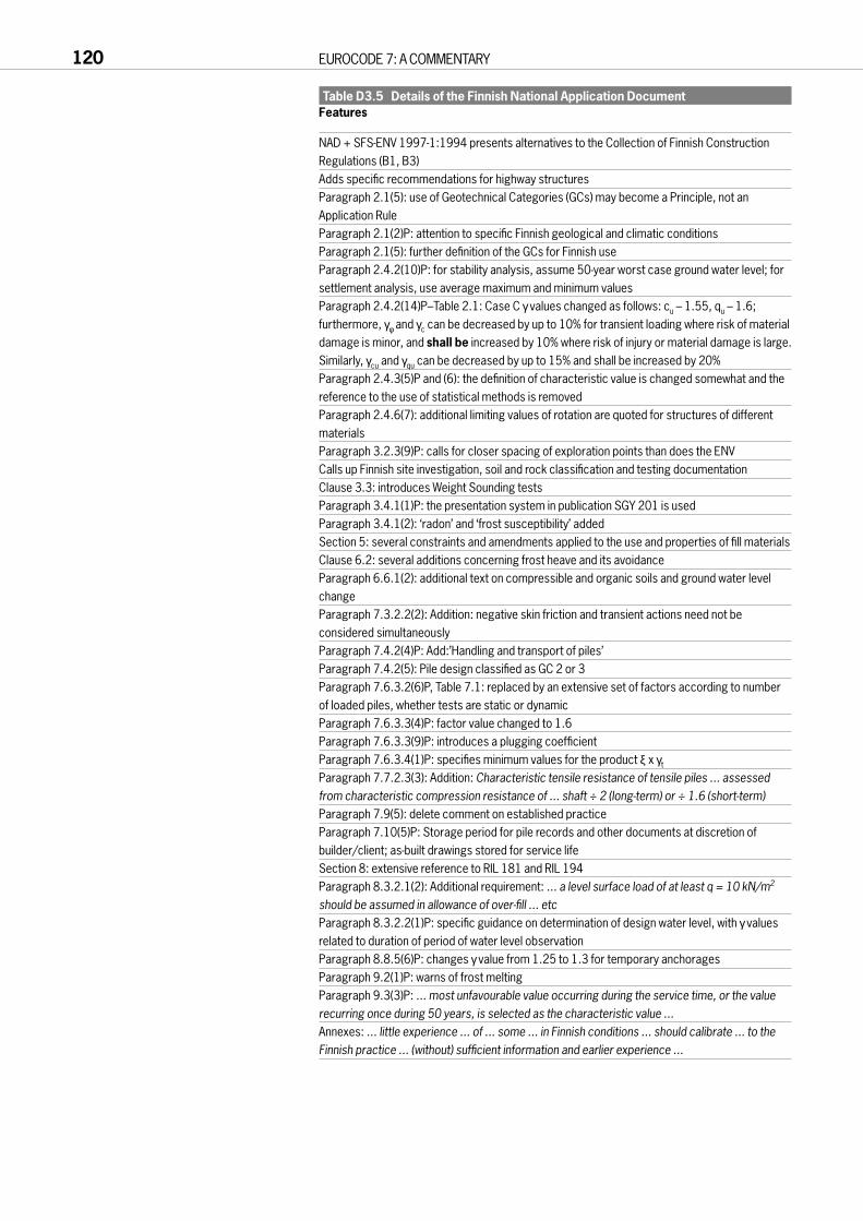
Table D3.5 Details of the Finnish National Application DocumentFeatures
NAD + SFS-ENV 1997-1:1994 presents alternatives to the Collection of Finnish ConstructionRegulations (B1, B3)Adds specific recommendations for highway structuresParagraph 2.1(5): use of Geotechnical Categories (GCs) may become a Principle, not anApplication RuleParagraph 2.1(2)P: attention to specific Finnish geological and climatic conditionsParagraph 2.1(5): further definition of the GCs for Finnish useParagraph 2.4.2(10)P: for stability analysis, assume 50-year worst case ground water level; forsettlement analysis, use average maximum and minimum valuesParagraph 2.4.2(14)P–Table 2.1: Case C γvalues changed as follows: cu – 1.55, qu – 1.6;furthermore, γφ and γc can be decreased by up to 10% for transient loading where risk of materialdamage is minor, and shall be increased by 10% where risk of injury or material damage is large.Similarly, γcu and γqu can be decreased by up to 15% and shall be increased by 20%Paragraph 2.4.3(5)P and (6): the definition of characteristic value is changed somewhat and thereference to the use of statistical methods is removedParagraph 2.4.6(7): additional limiting values of rotation are quoted for structures of differentmaterialsParagraph 3.2.3(9)P: calls for closer spacing of exploration points than does the ENVCalls up Finnish site investigation, soil and rock classification and testing documentationClause 3.3: introduces Weight Sounding testsParagraph 3.4.1(1)P: the presentation system in publication SGY 201 is usedParagraph 3.4.1(2): ‘radon’ and ‘frost susceptibility’ addedSection 5: several constraints and amendments applied to the use and properties of fill materialsClause 6.2: several additions concerning frost heave and its avoidanceParagraph 6.6.1(2): additional text on compressible and organic soils and ground water levelchangeParagraph 7.3.2.2(2): Addition: negative skin friction and transient actions need not beconsidered simultaneouslyParagraph 7.4.2(4)P: Add:’Handling and transport of piles’Paragraph 7.4.2(5): Pile design classified as GC 2 or 3Paragraph 7.6.3.2(6)P, Table 7.1: replaced by an extensive set of factors according to numberof loaded piles, whether tests are static or dynamicParagraph 7.6.3.3(4)P: factor value changed to 1.6Paragraph 7.6.3.3(9)P: introduces a plugging coefficientParagraph 7.6.3.4(1)P: specifies minimum values for the product ξ x γt
Paragraph 7.7.2.3(3): Addition: Characteristic tensile resistance of tensile piles ... assessedfrom characteristic compression resistance of ... shaft ÷ 2 (long-term) or ÷ 1.6 (short-term)Paragraph 7.9(5): delete comment on established practiceParagraph 7.10(5)P: Storage period for pile records and other documents at discretion ofbuilder/client; as-built drawings stored for service lifeSection 8: extensive reference to RIL 181 and RIL 194Paragraph 8.3.2.1(2): Additional requirement: ... a level surface load of at least q = 10 kN/m2
should be assumed in allowance of over-fill ... etcParagraph 8.3.2.2(1)P: specific guidance on determination of design water level, with γvaluesrelated to duration of period of water level observationParagraph 8.8.5(6)P: changes γvalue from 1.25 to 1.3 for temporary anchoragesParagraph 9.2(1)P: warns of frost meltingParagraph 9.3(3)P: ... most unfavourable value occurring during the service time, or the valuerecurring once during 50 years, is selected as the characteristic value ...Annexes: ... little experience ... of ... some ... in Finnish conditions ... should calibrate ... to theFinnish practice ... (without) sufficient information and earlier experience ...
120 EUROCODE 7: A COMMENTARY

Table D3.6 Details of the Irish National Application DocumentFeatures
Paragraph 2.4.2(15): For ease of application, a table of öd values is provided for Cases A, B and CParagraph 2.4.6(7): total settlements for normal strip and pad footings are limited to 25 mm notthe 50 mm in EC7Paragraphs 3.1(3), 3.2.3(6)P and 3.3.2(2)P: Reference Standards: Relevant documents are BS 1377 and BS 5930Paragraphs 5.3.2(1)P and 5.3.4(2): Proctor density to be derived using Method 3.4 of BS 1377-4Paragraph 6.4(2)P: width of foundation should not be less than that specified in Part E ofTechnical Guidance Document A of the Building RegulationsParagraph 6.6.1(2), fourth sentence, amended to read: Normally, this depth may be taken as thegreater of 1.5 times the width of the footing or the depth at which the effective vertical stressdue to the foundation load amounts to 20% of the effective overburden stressParagraph 7.6.3.3(4): a clarifying statement is made, similar to the U.K. NADParagraphs 8.3.2.1(1) and 8.3.2.1(2) are both to be satisfiedParagraph 8.6.6(4) (and 2.4.2(15)): a model factor of unity to be used for Cases A, B and C
PART D THE WAY AHEAD 121
Eurocode 7: a commentary
Part E Worked examples
123
CONTENTS
E1 INTRODUCTION 126
E2 ULS DESIGN OF A PAD FOOTING ON COHESIONLESS GROUND 127
E2.1 Introduction to E2 to E4 127E2.2 Data and load factors for E2 127E2.3 ULS calculations 127E2.4 Settlement assessment 130
E3 ULS DESIGN OF A PAD FOOTING – SHORT TERM LOADING ON STIFF CLAY 131
E3.1 Data 131E3.2 Bearing capacity calculations 131
E4 ULS DESIGN OF SPREAD FOUNDATION FOR A TOWER 132
E4.1 Data and load factors 132E4.2 Calculations 132
E5 APPLICATIONS OF ANNEX D – SLS SETTLEMENT CHECK 134
E5.1 Data 134E5.2 Method D.1 134E5.3 Method D.2 135E5.4 Calculation of the effect of moment loading 135
E6 DESIGN OF A COMPRESSION PILE 137E6.1 Data 137E6.2 Calculations 137
E7 CHARACTERISTIC CAPACITY OF COMPRESSION PILES DERIVED FROM LOAD TESTS 139
E7.1 Calculations 139E7.2 Comparisons between sequences of pile test results 140
E8 DERIVATION OF BASE AND SHAFT COMPONENTS FROM A COMPRESSION PILE LOAD TEST 141
E8.1 Introduction and data 141E8.2 Method A calculations 141E8.3 Method B calculations 141E8.4 Method C calculations 141E8.5 Method comparisons 143
E9 INPUT TO STRUCTURAL DESIGN OF A PILE IN HEAVING GROUND 144
E9.1 Purpose 144E9.2 Data 144E9.3 Method 1 145E9.4 Method 2 145
124 EUROCODE 7: A COMMENTARY

E10 PILE SUBJECT TO DOWNDRAG 147E10.1 Data 147E10.2 Approach 147E10.3 Characteristic values of forces 147E10.4 Case C1 - downdrag force (D) taken as action 147E10.5 Case C2 - settlement taken as action 148E10.6 Case B1 - downdrag force taken as action 149E10.7 Case B2 - settlement taken as action 149E10.8 Conclusion and discussion 149
E11 USE OF ANNEX F IN STRUCTURAL DESIGN OF A TENSION PILE 150
E12 PILES IN TENSION DUE TO BUOYANCY EFFECTS OF AN UNDERGROUND STATION 151
E12.1 Introduction 151E12.2 Calculations 151E12.3 Comment 153
E13 DESIGN OF A CONCRETE STEM WALL 154E13.1 Data 154E13.2 Ultimate limit states 154E13.3 Serviceability limit states 157
E14 DESIGN OF A CANTILEVER SHEET PILE WALL 158E14.1 Data and method 158E14.2 Comparative calculations 159E14.3 Required bending resistance 160E14.4 Discussion 160
E15 DESIGN OF A PROPPED EMBEDDED WALL 161E15.1 Description of problem 161E15.2 Basic set of calculations 161E15.3 More refined calculation 164E15.4 SLS check 164E15.5 Comments 166E15.6 Other checks required by EC7 166E15.7 Detailed comparative study 167
E16 DESIGN OF A GROUND ANCHOR 171E16.1 Description of problem 171E16.2 Method 171E16.3 Testing 171E16.4 Use in the construction 171E16.5 Other design checks 171E16.6 Comment 172
E17 DESIGN OF SLOPE IN DRAINED GROUND 173E17.1 Introduction 173E17.2 Data 173E17.3 Discussion 174
E18 ULS CHECK ON A SIMPLE, POTENTIALLY BUOYANT STRUCTURE 175
PART E WORKED EXAMPLES 125

E1 INTRODUCTIONPart E of the commentary consists of worked examples, to which reference ismade in the other parts. The examples have been developed to illustratespecific points about the application of EC7, and this also governs the amountof detail presented. All examples follow the rules of EC7 and are presented ina step by step approach demonstrating the checks that are required incarrying out a conforming design. Some include more detailed explanationthan would normally be found in design calculations, whilst in other casesdetail has been omitted so as not to obscure the points being illustrated.
The design examples cover a range of common geotechnical structures and are divided into spread footings, piles, walls and slopes as shown in theTable E1.1.
Further examples of the application of EC7 may be found in Frank (1994),DIN (1996), Orr and O’Brien (1996), Simpson (1996) and Carder (1998).
Table E1.1 Design examplesExample Structure Design example title Main EC7 clausesno type
E2 Spread ULS design of a pad footing on 2.4.2 Section 6footing cohesionless ground Annex B 6.5.1 and .2
E3 Spread ULS design of a pad footing - 2.4.2 Section 6footing short term loading on stiff clay Annex B 6.5.1 and .2
E4 Spread Design of spread foundation for 2.4.2 Section 6footing a tower Annex B 6.5.1 to .4
E5 Spread Application of Annex D: SLS Annex Dfooting settlement check
E6 Pile Design of a compression pile 2.4.2 Section 77.6.3.3
E7 Pile Characteristic capacity of Section 7compression piles derived from 7.6.3.2pile load tests
E8 Pile Derivation of base and shaft 2.4.2 Section 7components from a 7.6.3compression pile load test
E9 Pile Input to structural design of a 2.4.2 Section 7pile in heaving ground 7.3.2.3
E10 Pile Piles subject to downdrag 7.3.2E11 Pile Input to structural design of a Annex F Section 7
tension pileE12 Pile Examples for piles in tension 2.4.2 Section 7
due to buoyancy effects of an 7.7.2.2underground station
E13 Wall Design of a concrete stem wall 2.4.2 Section 8Annex G 8.5.1
8.5.4 and .58.7.2
E14 Wall Design of a cantilever sheet Annex G Section 8pile wall 8.3.2
E15 Walls Design of a propped embedded Annex G Section 8wall 8.6.1
E16 Ground Design of a ground anchor Section 8anchor 8.6.2 and .5
8.8.2 and .5E17 Slope Design of a slope in drained 2.4.2 Section 9
ground 9.5E18 ULS check on a simple,
potentially buoyant structure
126 EUROCODE 7: A COMMENTARY

E2 ULS DESIGN OF A PAD FOOTING ON COHESIONLESS GROUND
E2.1 Introduction to E2 to E4Design examples E2 to E4 look at ULS stability for spread footings. E2considers the drained bearing capacity of a footing on a medium dense sandand gravel layer. E3 uses the same load case as the first example but has a firmto stiff clay as the foundation stratum. In E4, the stability of a tall lightstructure with wind loading is considered. All three examples make use of theequations for bearing capacity in Annex B and the clauses in Section 6 of EC7.
E2.2 Data and load factors for E2The pad footing shown in Figure E2.1 is to bedesigned for a structure with large live load. Thefoundation stratum is medium dense sand andgravel with characteristic shear strengthparameters of φ′ = 35° and c′ = 0 kPa. Thecharacteristic loading conditions are shown inTable E2.1.
Table E2.1 Characteristic actions and partial factorsAction Case B: Partial factor (γ) Case C: Partial factors (γ)(kN) Unfavourable Favourable Unfavourable Favourable
Permanent:vertical Gvk = 1000 γG = 1.35 1.0 1.0 1.0
Variable:vertical Qvk = 2000 γQ = 1.5 0 1.3 0horizontal Qhk = 300 γQ = 1.5 0 1.3 0
The vertical and horizontal components of the variable load derive from asingle source, hence they are factored together. A moment results from thehorizontal load which is applied to the structure at 2 m above the top of thepad footing.
In addition to the actions that are applied to the structure, the verticalweight of the pad footing should also be included in the bearing capacitycalculation. Unit weights of the ground and concrete are 20 kN/m3 and 24.5 kN/m3 respectively. The water table is at depth and can be ignored forthis example.
E2.3 ULS calculationsIn order to satisfy EC7, Cases B and C must both be satisfied. For Case B therequired dimension of the 0.75 m deep footing was calculated to be 2.5 msquare, while for Case C the required dimension was 3.0 m square. Thesedimensions were found by iteration. As Case C governed sizing of the footingin this instance, the calculations for the final iteration of this case will bepresented below.
PART E WORKED EXAMPLES 127
Gvk = 1000kN
Qvk = 2000kN
Sand, φ'k= 35°,γ = 20kN/m3
c' = 0 kPa
Qhk = 300kN
Concrete γ = 24.5kN/m3
Elevation
Plan
B = L
0.75m
2.0m
Figure E2.1 Spread footing loads and geometry

E2.3.1 Case CDesign vertical action at footing base:Vertical action (Vd) = γG (Gvk + Wvk) + γQ Qvk (Wvk = Weight of pad)
= 1.0 × (1000 + 24.5 × 3.0 × 3.0 × 0.75) + 1.3 × 2000= 1000 + 165 + 2600= 3765 kN.
Similarly the design horizontal and moment action effects at footing base:Horizontal action (Hd) = γG Ghk + γQ Qhk
= 1.0 × 0 + 1.3 × 300= 390 kN
Moment action (Md) = γG Gmk + γQ Qmk= 1.0 × 0 + 1.3 × (2 + 0.75) × 300= 1073 kN.m.
The expressions for bearing capacity factors and associated shape factorsare given in Annex B of the Eurocode, and discussed below. For φk′ = 35° andγφ = 1.25 (from Table 2.1), the design value φd′ = tan–1((tan35°) / 1.25) = 29.3°.The associated design bearing capacity factors for Nq and Nγ are 16.9 and 17.8respectively (Nc is not used as c′ = 0).
Effect of moment loadingThe effect of a moment loading on the footing is to move the centroid of theloaded area of the pad base away from the centre of the footing. To accountfor this in the calculation of allowable bearing capacity, it is assumed that theresistance of the ground to the applied actions is centred on the centre ofgravity of the applied load. As shown in Figure E2.2, the zone of unused basehas a width of 2eb where eb is the load eccentricity. There is no eccentricity inthe perpendicular direction, so el = 0. Hence the Effective Area (A′) in thiscase is L(B – 2eb).
eb = Md / Vd= 1073 / 3765 (kN.m/kN)= 0.285 m.
Hence B′ = B – 2eb= 3 – 2 × 0.285 = 2.43 m
L′ = L – 2el = L.
ULS design vertical bearing resistanceThe ULS design vertical bearing resistance is a combination of threecomponents, namely the cohesive strength of the ground, the verticaleffective stress in the ground at the formation level of the spread footing andthe buoyant unit weight of the ground beneath the spread footing. Thesethree components are combined with factors depending on the size of thefooting and the load combinations applied to the footing as shown below:R / A′ = Cohesion + Effective stress + Density
= Nc c′sc ic + q′ Nq sq iq + 0.5γ′ B′ Nγ sγ iγwhere R = design bearing resistance
N = bearing capacity factors = spread footing shape factori = load inclination factor
q′ = effective stress at formation levelγ′ = buoyant weight of ground beneath footing.
Bearing capacity factorsThe following equations for the bearing capacity factors are taken from EC7,Annex B:Nq = eπ tanφ′ tan2 (45 + φ′ / 2)Nγ = 2(Nq – 1) tanφ′ when δ ≥ φ′ / 2 (rough base)Nc = (Nq – 1) cotφ′.
128 EUROCODE 7: A COMMENTARY
B -2eb
2eb
l- 2el
2el = 0in example
PressureDistribution
Effective Area
Figure E2.2 Effective area for eccentricloading

Effect of shapeThe above expressions for bearing capacity factors (Nq etc) are for a stripfooting. Where the spread footing is not a strip, the change in ratio ofdimensions must be accounted for using shape factors sq, sγ and sc (sq and sc aregreater than or equal to unity while sγ is less than or equal to unity). This isdone by considering the ratio of effective width to effective length, ie:sq = 1 + (B′ / L′) × sin (φd′)
= 1 + (2.43 / 3.0) × sin 29.3 = 1.45.sγ = 1 – 0.3(B′ / L′)
= 1 – 0.3(2.43 / 3.0) = 0.76.sc is not needed because c′ is equal to zero in this example.
Effect of loading inclinationHorizontal loads change the inclination of the resultant load that is distributedover the effective area of the footing. Expressions for inclination factors aregiven for the situation where the horizontal load is parallel to B′ and where itis parallel to L′ . In this case, the horizontal load is parallel to B′ .iq = (1 – 0.7 H / (V + A′ × c′ × cotφd′))
3
= (1 – 0.7 × 390 / 3765)3 = 0.80.iγ = (1 – H / (V + A′ × c′ × cotφd′))
3
= (1 – 390 / 3765)3 = 0.72.ic is not needed because c′ is equal to zero in this example.
The ULS design bearing pressure for Case C isR / A′ = Nc c′ sc ic + q′ Nq sq iq + 0.5γ′ B′ Nγ sγ iγ (EC7, Eq B2)
= 0 + (0.75 × 20) × 16.9 × 1.45 × 0.8 + 0.5 × 20 × 2.43 × 17.8 × 0.76 × 0.72= 0 + 283 + 236= 530 kN/m2.
Note that in this case, the water table is at depth and hence q′ = q and γ′ = γ.
The required ULS design bearing resistance isQ / A′ = 3765 / (3.0 × 2.43)
= 516 kN/m2 < 530 kN/m2, hence OK.
E2.3.2 Case BAs stated previously Case B is not critical for sizing of the spread footing inthis example. This is demonstrated by checking Case B using the samemethod as Case C, with the appropriate partial factors on load and groundshear strength.
E2.3.3 Overall factor of safetyFor comparison, if the partial factors on load and shear strength are set to unitythen the ULS bearing resistance is equal to 8950 kN for the 3 m square footing.This is equivalent to a factor of safety on applied characteristic load of 2.8.
E2.3.4 ULS structural designOnce the size of the footing is fixed it is necessary to consider the appliedforces to allow for the structural design of the footing. In Table E2.1 above it isclear that the partial factors applied to actions are greater in Case B than inCase C. For structural design Case B governs. Hence for structural design thedesign actions are (Case B):Vertical action (Vd) = γG (Gvk + Wvk) + γQ Qvk
= 1.35 × 1000 + 1.35 × 4.5 × 3.0 × 3.0 × 0.75 + 1.5 × 2000= 1350 + 223 + 3000= 4573 kN.
PART E WORKED EXAMPLES 129

130 EUROCODE 7: A COMMENTARY
Similarly the design horizontal and moment action effects at footing base are:Horizontal action (Hd) = γG Ghk + γQ Qhk
= 1.35 × 0 + 1.5 × 300= 450 kN
Moment action (Md) = γG Gmk + γQ Qmk= 1.35 × 0 + 1.5 × (2 + 0.75) × 300= 1238 kN.m.
These actions should then be used in design of the footing using theappropriate EC2 for reinforced concrete design, assuming a linear distributionof bearing pressure beneath the footing (EC7, 6.8(2)).
E2.4 Settlement assessmentAssessment of the settlement for this footing is given in E5.

PART E WORKED EXAMPLES 131
E3 ULS DESIGN OF A PAD FOOTING – SHORT TERM LOADING ON STIFF CLAY
E3.1 DataThe same loads are applied in this example as the footing in E2, but in thiscase the pad footing is on a stiff overconsolidated clay. The characteristicstrength of the clay, cuk, is 75 kPa and a check on undrained conditions only iscarried out in this example, as the critical loading is short-term.
E3.2 Bearing capacity calculationsUsing the formulae in Annex B.2 for undrained conditions, the length of sideof the footing for Case B was 3.75 m while for Case C is was 4.0 m. Hence, asfor E2, Case C is critical and B = L = 4.0 m. This may be checked as follows.For Case C, the design vertical action at footing base:Vertical action (Vd) = γG (Gvk + Wvk) + γQ Qvk (Wvk = weight of pad)
= 1.0 × (1000 + 24.5 × 4.0 × 4.0 × 0.75) + 1.3 × 2000=1000 + 294 + 2600=3894 kN.
The design horizontal and moment actions are as in E2, 390 kN and1073 kNm, respectively.
In Case C the design strength for the clay incorporates the partial factor γcuof 1.4 to give:cud = cuk / γcu
= 75 / 1.4= 53.5 kN/m2.
The allowable bearing resistance is R / A′ = (2 + π) sc ic cud + q (EC7, Eq B1)where R = design bearing resistance
A′ = effective areasc = 1 + 0.2 (B′ / L′)ic = 0.5 (1 + (1 – H / A′ cud)
1/2)q = total overburden pressure at base level.
The effective width B′ is equal to 3.45 m giving the shape factor (sc) a value of 1.17.
The design horizontal load is equal to 390 kN and the effective area is equalto 13.8 m2 giving the inclination factor a value of 0.84.
Hence the ULS design vertical bearing resistance is:R / A′ = (2 + p) sc ic cu + q
= 5.14 × 1.17 × 0.84 × 53.5 + 0.75 × 20= 285 kN/m2.
The required ULS design vertical bearing resistance is:Vd / A′ = 3894 / (4.0 × 3.45)
= 282 kN/m2 < 285 kN/m2, hence OK.In Paragraph 6.5.3(9)P the horizontal shear action at foundation level is
limited to A′cu. The undrained shear strength of the ground cu used here isthat available at the soil structure interface; ‘adhesion’ would be a better term,as used in 8.5.1(4). (If this is taken to be equal to cu in the body of the clay, thenthe formula for the inclination factor can only be evaluated for Sd ≤ A′cu.)
In Paragraph 6.5.3(9)P a second limit is placed on thehorizontal shear where water may penetrate to the base of thefooting and prevent suctions from developing (see Figure E3.1).In this case, the ratio Sd / Vd is limited to 0.4. For this examplethe ratio of Hd / Vd is 390 / 3894 = 0.1 < 0.4, hence OK.
E3.2.1 Overall factor of safetyIf the partial factors on load and shear strength are set to unitythen the ultimate bearing resistance is equal to 5852 kN; thecharacteristic vertical load is 3294 kN. This is equivalent to afactor of safety on applied characteristic load of 1.78.
Vd
Hd
cu
Check 6.5.3(9)P Hd < A’cu
6.5.3(9)P Hd < 0.4 Vd
A’
Figure E3.1 Limit on horizontal loads

E4 ULS DESIGN OF SPREAD FOUNDATION FOR A TOWER
E4.1 Data and load factorsThis example considers the bearing capacity of a talllightweight structure which is subjected to significanthorizontal loading (eg a windmill or chimney). Thecharacteristic actions and partial factors are shown in FigureE4.1 and Table E4.1.
A moment results from the horizontal load which isapplied to the structure at 10 m above the top of the padfooting. The pad footing is 2 m deep and is situated on a drymedium dense sand and gravel layer with φ′ = 35° and c′ = 0 kPa.
Table E4.1 Characteristic actions and partial factorsAction Case B: Partial factor (γ) Case C: Partial factors (γ)(kN) Unfavourable Favourable Unfavourable Favourable
Permanent:vertical Gvk = 600 γG = 1.35 1.0 1.0 1.0
Variable:vertical Qvk = 0 γQ = 1.5 0 1.3 0horizontal Qhk = 300 γQ = 1.5 0 1.3 0
E4.2 CalculationsThe required size of footing was calculated for both cases B and C. For Case B,it is necessary to consider the permanent vertical actions both as favourableand unfavourable. In this example, Case B with the permanent vertical actionsfavourable was found to be the critical case with a required footing dimensionof 5.6 m square. The required dimension for Case C was 5.4 m square. Hence,Case B was marginally critical for sizing of the pad footing (ie critical forgeotechnical stability). This possibility was discussed in B5.4.
For Case B with favourable permanent vertical load, the design actions are:Vertical Vd = (600 + 5.6 × 5.6 × 2 × 24.5) × 1.00
= 2137 kNHorizontal Hd = 300 × 1.5
= 450 kNMoment Md = 300 × (10 + 2) × 1.5
= 5400 kNm.The calculations showed that for such a high, light structure the moment
induced eccentricity resulted in the resultant force passing close to the edgesof the footing:eb = Md / Vd
= 5400 / 2137 = 2.53 mand B′ = B – 2eb
= 5.6 – 2 × 2.53 = 0.54 m.
Using the equations in Annex B and as used in E2 the design bearingresistance R is:R / A′ = Nc c’ sc ic + q′ Nq sq iq + 0.5γ′ B′ Nγ sγ iγ (EC7, Eq B2)
= 0 + (2 × 20) × 33.3 × 1.05 × 062 + 0.5 × 20 × 0.54 × 45.2 × 0.97 × 0.49= 0 + 871 + 116= 987 kN / m2.
132 EUROCODE 7: A COMMENTARY
Sand, φ'k= 35°, γ = 20kN/m3
B = L
10m
2.0m
Qhk = 300kN
Gvk = 600
Figure E4.1 Loading for a tall, lightweight structure

The required ULS design vertical bearing resistance is:Vd / A′ = 2137 / (5.6 × 0.54)
= 707 kN/m2 < 987 kN/m2, hence OK.In this situation a small increase in applied horizontal force to the structure
(and hence an increase in moment) would lead to overturning of thefoundation and hence in this situation it is vital to size the footing to allow forunforeseen situations. EC7, 6.5.4 requires that in situations such as these,where the design load passes outside the middle 2/3 of the footing, anallowance must be made for construction tolerances. This will typicallyrequire that the footing be extended a further 0.1 m, increasing B′ to about0.64 m and the footing dimensions to 5.8 m square. (In situations such as this apiled foundation solution may result in a lower cost foundation.)
The resulting bearing pressure for the factored loads of Case B is 707 kPa.For the serviceability loading it is less than 200 kPa, the precise valuedepending on the assumed distribution of bearing pressure.
The factor of safety against bearing capacity failure using characteristicloads and soil shear strengths is 10.3. This appears to be large and is mainly aresult of the large moment loading and its influence on the magnitude of B′ inaddition to increases in the bearing capacity factors and inclination factors.For SLS considerations the potential of the footing to rock under windloading should be considered, as in E5.4.
PART E WORKED EXAMPLES 133

E5 APPLICATIONS OF ANNEX D – SLS SETTLEMENT CHECK
E5.1 DataConsidering the load case for the pad footing in E2, it is necessary to calculatethe settlement of the footing for SLS conditions.
The ground conditions at the footing are medium-dense sand and gravel toa depth of 7 m with an average SPT value of 20. This sand and gravel layeroverlies a 13 m depth of overconsolidated clay. The characteristic Young’smoduli of these two layers are E′ = 50 MPa for the sand and gravel and E′ = 15 MPa increasing to 32 MPa at 13 m below the clay surface for the clay. At 20 m depth there is a rigid rock stratum.
Paragraph 2.4.2(18)P states that partial factors of unity shall be used for allpermanent and variable actions for verification of the serviceability limit state.Hence, the design actions are:Vertical Vd = 3165 kN(Horizontal Hd = 300 kN)(Moment Md = 825 kN.m).
Annex D proposes two methods (and two variants). Both methods arepresented below. Only movements under vertical loading will be consideredin E5.2 and E5.3. Rocking will be checked in E5.4.
E5.2 Method D.1Isotropic elasticity is assumed to apply to this situation. The settlement of theloaded area may be calculated by hand or by using proprietary software.
Fadum (1948) presents relationships for the change in vertical stressbeneath an uniformly distributed load in the form:∆σz = Σ qIσwhere q is the uniformly distributed load
Iσ is the influence factor depending of geometry of loaded area and position of soil element relative to loaded area. Stress changes are calculated for a set of loaded areas all of which have a corner above the point being investigated.
For a point some 2 m beneath the centre of the loaded area of dimensions 3 m by 3 m, the change in stress for the imposition of a UDL of 352 kN/m2 is:∆σz = Σ qIσ.
The Equivalent Loaded Area is 4 rectangles with dimensions 1.5 m by 1.5 m arranged symmetrically above the point at 2 m depth (superposition is assumed). The value of factor Iσ for one of these areas is 0.136 (Fadum (1948))= 4 × 352 × 0.136 = 192 kN/m2.
The strain in this element will be influenced by both the change in verticaland in horizontal stresses. For this element the change in horizontal stress iscalculated to be approximately 6% of the change in vertical stress (in thisinstance). The vertical strain (εz) can then be calculated using the equation:εz = ∆σz / E′ – ν′∆σx / E′ – ν′∆σy / E′ (x and y are horizontal directions)
= ∆σz / E′ (1 – 2 × 0.3 × 0.06) (ν′ is 0.3 in this case)= 192 / 50 000 (1 – 0.04)= 0.37%.To obtain the full settlement of the loaded area, it is necessary to integrate
along a vertical line the strain magnitude in each element of soil; the smallerthe elements the more accurate the solution.
134 EUROCODE 7: A COMMENTARY

This process of integration is most easily carried out on a computer. Theresults of a settlement analysis obtained using the Oasys program VDISP areshown on Figure E5.1. The maximum settlement is 24.3 mm, situated in thecentre of the loaded area, reducing to an average of 15 mm along each edge.To compare the strain calculated by the program and that calculated above,the displacement at the centre line of the loaded area at 1.9 m depth was 17.0 mm while at 2.1 m depth it was 16.3 mm. Hence the computed strain was(17.01 – 16.34) / 200 × 100% = 0.34% and this compares reasonably with thehand calculated strain above. This settlement calculation ignores the stiffnessof the structure.
E5.3 Method D.2In part 2 of Annex D, the ‘Adjusted Elasticity Method’ is presented. Thismethod allows the results of field measurements or soil tests to be used toprovide a back calculated stiffness for the ground which can then be usedelsewhere on a particular site. A simple form of equation is presented (Eq. D.1), a variation of which is presented below (settlement for a rigidrectangular element):ρz = q (BL)1/2 (1 – ν2) / (βz E)where βz is a factor depending on the ratio L / B (increasing from 1.06 to 1.4
for L / B = 1 to 10).Hence, for the loaded foundation above with q = 352 kN/m2 and B = 3.0 m,
L = 3.0 m and E = 50 000 kN/m2, the plate settlement is:ρz = 352 (3.0 × 3.0)1/2 (1 – 0.32) / (1.06 × 50 000)
= 19.9 mm.This uniform settlement is similar to the average settlement calculated
using the computer program. The inclusion of the clay layer in the VDISPcalculation will cause larger settlement at depth as compared to the assumptionin the Method D.2 calculation which assumes uniform ground properties.
E5.4 Calculation of the effect of moment loadingMoment loading could be incorporated in Method D.1 by dividing the verticalload into strips that would result in the correct moment being applied aboutthe centre of the footing. The result on moment loading would notsignificantly alter the settlement at the centre point of the footing. In MethodD.2, equations similar to those for settlement calculation exist for momentloading (Poulos and Davis (1974)) as shown above for E4.
PART E WORKED EXAMPLES 135
3
2
1
0
-1
-2
-3
-4
-5 -4 -3 -2 -1 0 1 2 3 4 5
Y (m)
X (m)
8
12
1620
24
Figure E5.1 Settlement analysis for spread footings (settlement in mm)
From the data in E4, the design loadings for SLS conditions at the base ofthe 5.6 m square base are:
Vd = 2137 kNHd = 300 kNMd = 3600 kN.The resulting load eccentricity is 1.68 m (3600 / 2137), well outside the
middle third of the foundation. The middle third check is useful as it helps the designer to visualise if part of the foundation will detach during loading; itis not, however, an EC7 criterion (see C6.5.4(1)P). Where the loadeccentricity lies outside the middle third of the foundation base, it is possiblethat an elastic calculation of rocking will underestimate movements. In thisexample the fact that the resulting load is outside the middle third of thefooting will be considered in an approximate fashion during the calculation offooting rotation.
Poulos and Davis (1974) state that the rotation of the foundation can becalculated using the following equation:
φ= M (1 – ν2) Iθ / (b2 × l × E)where φ= rotation in radians
M = moment in the direction of dimension ‘B’ν = Poisson’s ratio of groundIθ = geometrical factor
b, l = dimensions of footing, positive contact areaE = Young’s modulus of ground.
The eccentricity of the characteristic load eb is 1.68 m and hence theeffective width B′ is (5.6 – 2 × 1.68) 2.23 m. This effective width is thedimension which when loaded by a uniformly distributed load results in theappropriate vertical reaction to the applied vertical and moment loading.When, as in this case, the eccentricity is outside the middle third, the positivecontact width will be 1.5 × B′ or 3.35 m (clearly when the eccentricity is insidethe middle third the positive contact width is B). The calculation of footingrotation can then be carried out using b = 3.35 m and l = 5.6 m. The assumedground conditions are E = 50 000 kN/m2 and ν = 0.3 and the rotation of thefooting is:
φ= ± M (1 – ν2) Iθ / (b2 × l × E)= ± 3600 × (1 – 0.32) × 3.4 / (3.352 × 5.6 × 50,000)= ± 0.0035 rad.
The actual elastic rocking δ is :δ = ± φB / 2
= ± 0.0035 × 5.6 / 2= ± 9.9 mm.
The rocking movement at the top of the tower will be ± 42 mm and thisrocking movement must be checked against the requirements of the project. If it is not acceptable, a further increase in foundation size, or a change offoundation type, will be required.
136 EUROCODE 7: A COMMENTARY

E6 DESIGN OF A COMPRESSION PILE
E6.1 DataA structure is to be supported on bored piles. Each pile supports a singlecolumn with vertical characteristic loading of Gk = 1000 kN (permanent) andQk = 300 kN (variable). Based on this load information and the soil propertiesshown in Figure E6.1 it is necessary to calculate the required toe level of a 0.6 m diameter bored pile.
The following mean relationships for pile resistance will be used, using thesubscript ‘µ’ to denote mean, or most probable, ground properties and
resistances. The relationships must be based onthe results of a large number of pile tests insimilar ground conditions, as per 7.4.1(1)P.
Shaft resistance in gravel:qsiµ = Ks σv′ tan δµ
= 0.7 σv′ tan φµ′ .Shaft resistance in clay:
qsiµ = 0.6 cuµ.Base resistance in clay:
qbµ = 9 cuµ.The calculations and notation follow 7.6.3.3.
E6.2 CalculationsBefore calculating the required pile length, it isnecessary to calculate the characteristicresistance of the pile elements (incrementallengths of shaft and base). This is done by usingthe mean pile information above and Paragraph7.6.3.3(4)P, where the ratio between measuredresistance qm and characteristic resistance qk isrequired to be at least 1.5 (ie qm / qk ≥ 1.5). Thederivation of the characteristic property fromthe mean property is analogous to Paragraph7.6.3.2(6)P used for obtaining the characteristicbearing resistance from pile load tests.
Hence, the characteristic resistances are:characteristic shaft resistance in gravel:qsik = 0.7 σv′ tan φµ′ / 1.5
= 0.35 σv′characteristic shaft resistance in clay:qsik = 0.6 cuµ / 1.5
= 0.4 cuµcharacteristic base resistance in clay:qbk = 9 cuµ / 1.5
= 6 cuµ.These are also the design resistances for ULS Case B as per Table 2.1 where
all partial factors on ground properties are equal to unity.For the ULS design, Cases B and C (Table 2.1) must be checked. The
combination of partial factors on design pile resistance and design actions aretaken from EC7, Tables 2.1 and 7.2, as shown in Table E6.1.
Table E6.1 Combined use of partial factors from EC7, Tables 2.1 and 7.2.Actions (Table 2.1) Pile Resistance (bored)Permanent Variable Design load (Vd) γb γs
Case B 1.35 1.5 1800 kN 1.0 (Table 2.1) 1.0 (Table 2.1)Case C 1.0 1.3 1390 kN 1.6 (Table 7.2) 1.3 (Table 7.2)
PART E WORKED EXAMPLES 137
Gk =1000kN
Qk = 300kN
0m
-3m
-5m
Gravelφµ’ = 37°, γ = 19kN/m3
ClayShaft: cuµ = 100kN/m2 (average)Base: cuµ = 150kN/m2
Pile base level ?
Figure E6.1 Compression pile with characteristic actions and mean groundproperties

Hence, for derivation of the design resistance using Case C:design shaft resistance in gravel:qsid = qsik / γs
= 0.35 σv′ / 1.3= 0.27 σv′
design shaft resistance in clay:qsid =qsik / γs
= 0.4 cuµ / 1.3= 0.31 cuµ
design base resistance in clay:qbd = qbk / γb
= 6 cuµ / 1.6= 3.75 cuµ.
The required pile length for the two load cases can then be calculated usingthe following equations, with the appropriate design resistances:design base resistance:Rbd = qbd . Ab (Ab = base area = πr2)design shaft resistance:Rsd = Σ qsik . Asi (Asi = shaft area for length ‘i’ of shaft = πD.Li).
The calculations in Table E6.2 show that Case C is critical in this case forthe sizing of the pile.
Table E6.2 Calculations for compression pileCase B Case C
Length of shaft in gravel (m) 5 5Average σv′ in gravel (kN/m2) 43.5 43.5Rsk gravel (kN) 144 144Rsd gravel (kN) 144 110Rbk clay (kN) 254 254Rbd clay (kN) 254 159Design action Vd (kN) 1800 1390Required Rsd clay (kN) 1800 – 144 – 254 = 1402 1390 – 110 – 159 = 1121Required Rsk clay (kN) 1402 × 1.0 = 1402 1121 × 1.3 =1457
– not critical – criticalHence L shaft clay (m) Not critical 19.4Pile base level (m Datum) Not critical – 24.4
The SLS design case (pile settlement) has not been considered here. Thiswould be required in a complete pile design.
138 EUROCODE 7: A COMMENTARY
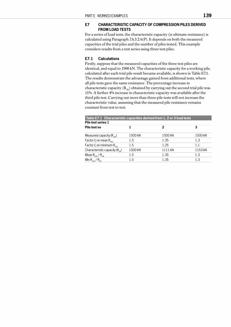
E7 CHARACTERISTIC CAPACITY OF COMPRESSION PILES DERIVEDFROM LOAD TESTS
For a series of load tests, the characteristic capacity (ie ultimate resistance) iscalculated using Paragraph 7.6.3.2.6(P). It depends on both the measuredcapacities of the trial piles and the number of piles tested. This exampleconsiders results from a test series using three test piles.
E7.1 CalculationsFirstly, suppose that the measured capacities of the three test piles areidentical, and equal to 1500 kN. The characteristic capacity for a working pile,calculated after each trial pile result became available, is shown in Table E7.1.The results demonstrate the advantage gained from additional tests, where all pile tests gave the same resistance. The percentage increase incharacteristic capacity (Rck) obtained by carrying out the second trial pile was11%. A further 4% increase in characteristic capacity was available after thethird pile test. Carrying out more than three pile tests will not increase thecharacteristic value, assuming that the measured pile resistance remainsconstant from test to test.
Table E7.1 Characteristic capacities derived from 1, 2 or 3 load testsPile test series 1Pile test no 1 2 3
Measured capacity (Rcm) 1500 kN 1500 kN 1500 kNFactor ξ on mean Rcm 1.5 1.35 1.3Factor ξ on minimum Rcm 1.5 1.25 1.1Characteristic capacity (Rck) 1000 kN 1111 kN 1153 kNMean Rcm / Rck 1.5 1.35 1.3Min Rcm / Rck 1.5 1.35 1.3
PART E WORKED EXAMPLES 139

E7.2 Comparisons between sequences of pile test results
Suppose that, in a second series of pile tests, threepiles were tested and the measured ultimatecapacities were 1550 kN, 1500 kN and 1400 kN.The analysis of the pile tests results would dependin the sequence in which the results becameavailable, as shown in Tables E7.2a, b & c, andFigures E7.1a, b & c.
Table E7.2a Pile test series 2aPile test no 1 2 3
Rcm 1550 kN 1500 kN 1400 kNMean Rcm 1550 kN 1525 kN 1483 kNξ on mean Rcm 1.5 1.35 1.3ξ on min Rcm 1.5 1.25 1.1Rck 1033 kN 1130 kN 1141 kNCritical Mean + Min Mean Mean
Table E7.2b Pile test series 2bPile test no 1 2 3
Rcm 1400 kN 1500 kN 1550 kNξ on mean Rcm 1.5 1.35 1.3ξ on min Rcm 1.5 1.25 1.1Rck 933 kN 1074 kN 1141 kNCritical Mean + Min Mean Mean
Table E7.2c Pile test series 2cPile test no 1 2 3
Rcm 1500 kN 1400 kN 1550 kNξ on mean Rcm 1.5 1.35 1.3ξ on min Rcm 1.5 1.25 1.1Rck 1000 kN 1074 kN 1141 kNCritical Mean + Min Mean Mean
The tables and graphs show that when there is areasonable variation between the capacitymeasured in the three tests (10% variation) thecharacteristic capacity always increases, even if thestrongest pile is tested first and the weakest piletested last (Series 2a). Hence, where a largenumber of piles are to be constructed there may besignificant savings available if more than one piletrial test is carried out.
If the variation in ultimate resistance betweenpiles is large (more than 20%) then it is possible thatthe characteristic resistance will decrease as thenumber of pile tests increases (assuming a strongpile was tested first). In this case it is necessary thatthe designer investigates the wide variation in pilecapacities prior to proceeding to construction.When this occurs the minimum measured capacity(rather than the mean) will control thecharacteristic capacity.
140 EUROCODE 7: A COMMENTARY
Rck
(kN
)
1200
1100
1000
900
Number of pile tests
0 1 2 3 4
c) Series 2c
Rck
(kN
)
1200
1100
1000
900
Number of pile tests
0 1 2 3 4
b) Series 2b
Rck
(kN
)1200
1100
1000
900
Number of pile tests
0 1 2 3 4
a) Series 2a
Figure E7.1 Pile test series

E8 DERIVATION OF BASE AND SHAFT COMPONENTS FROM A COMPRESSION PILE LOAD TEST
E8.1 Introduction and dataThe ULS design pile load capacity is obtained froma single pile load test using three methods ofinterpreting the pile load tests to failure.
Method A considers the maximum pile shaftcapacity by inspection;
Method B uses Chin (1972) to derive bothultimate shaft and base capacities; and
Method C uses the results of instrumentationwhich distinguishes between components of shaftand base resistance.
The pile has a 1.02 m diameter shaft and a 2.06 mdiameter base. The total length of the pile is 22 m.
E8.2 Method A calculationsFigure E8.1a shows the load-settlement pointsmeasured in the pile test, for which the ultimateresistance was 14.2 MN at a settlement/shaftdiameter ratio of δ / D = 10%. The pile shorteningline is also shown on Figure E8.1a. This line is theelastic compression of the pile assuming that thetotal imposed load results in compression of thewhole length of the pile shaft. The intersection ofthis pile shortening line with the pile load-defl ectioncurve is at approximately 6.2 MN (δ = 5 mm) and itis this load that may be assumed to approximatelyequal to the shaft friction of the pile. By inspection,it is therefore considered that the shaft resistance isabout 6.2 MN, so the base resistance is inferred tobe 8.0 MN.
E8.3 Method B calculationsFigure E8.1b shows the same data on a ‘Chin plot’.From this it could be inferred that the shaftcapacity is about 8.3 MN and the total ultimatecapacity (at very large displacement) 16 MN,giving a base capacity of 7.7 MN.
E8.4 Method C calculationsDuring the loading cycle, the test pile wasinstrumented at locations along the shaft and base.The load cells showed a shaft resistance of 6.7 MNand a base resistance of 7.5 MN at δ / D = 10%. Theresults for the shaft and base resistances are shownin Figure E8.1c.
In order to calculate the design resistance of thepile from the measured resistance in a pile load test,Paragraphs 7.6.3.2(6)P and 7.6.3.2(10)P must be used.
PART E WORKED EXAMPLES 141
a) Under-reamed pile, load-settlement curve
b) Chin plot
c) Instrumented test pile, load-section curve
16
14
12
10
8
6
4
2
0-20
Pile
hea
d lo
ad (
MN
)
Pile head settlement (mm)
Pile Pile shortening
0 20 40 60 80 100 120 140
A
2.5
2
1.5
1
0.5
0
Def
lect
ion/
Load
(m
m/M
N)
Pile head settlement (mm)
0 4 8 12 16
O
A
B
OA - Shaft dominatedBC - Base dominated
16
14
12
10
8
6
4
2
0-20
Pile
hea
d lo
ad (
MN
)
Pile head settlement (mm)
Total Shaft
0 20 40 60 80 100 120 140
A
Base
20
Figure E8.1 Design of a compression pile, assessing shaft and basecapacity from loading test

Paragraph 7.6.3.2(6)P considers the characteristic resistance of the pilebased on both the load test results and the number of load tests carried out(see E7):
Rck = Rcm / ξwhere Rck = the characteristic, k, resistance of the compression, c, pile test(s)
Rcm = the measured, m, resistance from the compression pile tests (only one test was carried out here)
ξ = a factor depending on the number of pile load tests and, where there is more than one test, whether the minimum Rcm or average Rcm is being considered (Table 7.1).
Paragraph 7.6.3.2(10) allows the design resistance to be derived from thecharacteristic resistance:Rcd = Rck / γ.
The partial factors (γ) are the equivalent of the ULS Case C factorspresented in Paragraph 2.4.2(14)P for use with ground properties. Values of γare provided for total pile capacity, shaft capacity and base capacity (Table 7.2).The value of γ is different for different types of pile installation (conventionalbored, continuous flight auger or driven). This example uses bored piles.
The design capacity of the pile is now calculated for Method C.For a single pile load test the value of ξ is 1.5 (Rcm for average and minimum
conditions are obviously the same). The measured pile resistance was 14.2MN, hence the characteristic resistances are:Rck = Rcm / ξRck = 14.2 / 1.5
= 9.47 MN total resistanceRsk = 6.7 / 1.5
= 4.47 MN (subscript ‘s’ for shaft)Rbk = 7.5 / 1.5
= 5.0 MN (subscript ‘b’ for base).The designer may then chose between two approaches:
either Rcd = Rck / γt= 9.47 / 1.5 = 6.31 MN (γt = 1.5 on total resistance)
or Rsd = Rsd + Rbd= 3.44 + 3.13 = 6.57 MN on combined shaft and base
where Rsd = 4.47 / 1.3 = 3.44 MN (γs = 1.3 on shaft)
+ Rbd = 5.0 / 1.6 = 3.13 MN (γb = 1.6 on base).
In this instance the capacity derived by resolving the total resistance intoshaft and base components is some 4% larger than the resistance of the pilewhen no distinction is made between shaft and base, providing a moreeconomic design which is in compliance with the code.
142 EUROCODE 7: A COMMENTARY

E8.5 Method comparisonsThe results for the three Methods are summarised in Table E8.1. In the table,the displacement that is appropriate to the total resistance in each Method isstated. It is clear that the displacements for Methods A and C are the same(the measured resistance) while Method B is for a larger displacement. Inorder to calculate the design pile resistance, the shaft and base resistance isexpressed as a fraction of the total resistance. This breakdown between shaftand base resistance is then used with the measured ultimate compressionresistance to obtain the design resistance of the pile.
Table E8.1 Method comparisonMethod A: Method B: Method C:By inspection Chin method By measurement
Shaft resistance (MN) 6.2 8.3 6.7Base resistance (MN) 8.0 7.7 7.5Total resistance (MN) 14.2 16.0 14.2
at δ= 10% D δ= large at δ= 10% DRatio shaft/total 0.437 0.519 0.472
resistanceRatio base/total 0.563 0.481 0.528
resistanceMeasured ultimate 14.2 14.2 14.2
compression resistance, Rcm (MN)
Characteristic ultimate 9.47 9.47 9.47compression resistance, Rck (MN)Rck = Rcm / 1.5 (Table 7.1)
Characteristic shaft 9.47 × 0.437 9.47 × 0.519 9.47 × 0.472 resistance, Rsk (MN) = 4.14 = 4.91 = 4.47
Characteristic base 9.47 × 0.563 9.47 × 0.481 9.47 × 0.528 resistance, Rbk (MN) = 5.33 = 4.56 = 5.00
Case C design shaft 4.14 / 1.3 4.91 / 1.3 4.47 / 1.3 resistance, Rsd (MN) = 3.18 = 3.78 = 3.43
Case C design base 5.33 / 1.6 4.56 / 1.6 5.00 / 1.6 resistance, Rbd (MN) = 3.33 = 2.85 = 3.13
Case C design total 6.51 6.63 6.56resistance, Rcd (MN)
In this example, the division between shaft and base resistance was variedbetween the three Methods. Nevertheless, the resulting design totalresistances for ULS Case C differed by less than 2%, due partially to the evendistribution between base and shaft resistances.
It is important to note that although there is some uncertainty in theassessment of the measured ratio of shaft to base resistance, the calculationuses the measured total resistance, which is clearly determined in the test tobe 14.2 MN.
PART E WORKED EXAMPLES 143

E9 INPUT TO STRUCTURAL DESIGN OF A PILE IN HEAVING GROUND
E9.1 PurposeThis example is used to illustrate the value of considering ground-structureinteraction in order to reduce design forces in a structure.
E9.2 DataEC7, 7.3.2.3 considers the reaction of a pile when theground that supports it swells. It states that themovement of the ground shall generally be treated as anaction. (This is an ‘indirect action’ as defined in EC1,4.1(1)). The example given below considers the ULSstate for structural design of the pile to withstandground heave prior to placement of permanent verticalload on the pile. The pile and ground conditions aresummarised in Figure E9.1. No consideration of theallowable displacement or calculation of crack width inthe pile section is presented.
In this example Case B is critical. The partial factor forCase B is 1.35 and this can be applied to the forcecalculated using characteristic ground strength. Theresulting design force (tension) will be greater than thatcalculated for Case C where there is a factor of 1.25applied to tanφ′. (Note that in this case tanφ′d = tanφ′k / γφ > tanφk′ as strong ground isdetrimental to the pile integrity. EC7 does not give a
value for the partial factor for this case, but γφ = 1 / 1.25 = 0.8 is assumed here.)Strictly, it might be argued that if ground displacement is treated as the
action, the factor of 1.35 should be applied to displacement, and not to theresulting forces, which are action effects. In this case, it could be found thatthe design action effects from Case B would be smaller, and Case C becomescritical. In the approach shown here, the partial load factor is applied to theaction effect. Further discussion of this question is presented in E10.
Two calculations are presented for the maximum mobilised tensile force inthe pile.a The first calculation considers the maximum forces that could be mobilised
in the pile if the pile were considered to be infinitely stiff. This calculationprovides an upper limit to the design tensile force in the pile.
b The second calculation incorporates the stiffness of the pile and assumesthat the pile cracks. The stiffness of the pile is calculated using only thereinforcement in the pile.
In both cases, allowance is made for the weight of the pile.
144 EUROCODE 7: A COMMENTARY
Clay:γb = 20kN/m3
φk = 23°E = 12 + 1.2z MPa(z is depth below ground)
Pile:15m long and 1m diameter
Figure E9.1 Pile in heaving ground

E9.3 Method 1In this upper limit calculation of the ultimate pile tensile force the pile skinfriction is assumed to be fully mobilised along the pile shaft. This isconservative, as mobilised skin friction is known to be related to the sheardisplacement between pile and surrounding ground. The level at which thecumulative skin friction, starting from the pile base, equals the cumulative skinfriction, starting at the pile head, is called the balance point and this is thepoint of maximum tensile stress in the pile. Typically, the balance point will beat about two thirds the depth of the pile shaft. The calculated stressdistribution, including the self-weight of the pile, is shown in Figure E9.2. Themaximum tensile stress due to heaving ground around the pile is 1411 kPa,equivalent to a tensile force of 1108 kN in the pile.
E9.4 Method 2In this calculation, both the stiffness of the ground and the stiffness of the pileare considered (in contrast to Method 1). This is most easily carried out usinga finite element program (or similar) which will iterate to a solution withcompatible stresses and strains. The cumulative stress in the pile shaft derivedis shown in Figure E9.2.
The maximum tensile stress in the pile shaft is 922 kPa, which is 35% lessthan the value calculated in Method 1. The stress of 922 kPa is equivalent to aforce of characteristic tensile force (Vk) of 724 kN, which should be used fordesign of the pile reinforcement.
The required area of tensile steel can then be calculated using thischaracteristic force and criteria in EC2.
The design tensile force is:Vd = Vk × γG
= 724 × 1.35= 978 kN.The characteristic yield strength (fyk) of the steel used is 460 N/mm2 and
the design yield strength is:fyd = fyk / γm
= 460 / 1.15= 400 N/mm2.Hence the required area of steel (As) is:
As = Vd / fyd= 978 / 0.4= 2445 mm2.
PART E WORKED EXAMPLES 145
Dis
tanc
e fr
om p
ile b
ase
(m)
15
10
5
0-1500 -1000 -500 0
Pile stress (kPa). Negative is tension
Method 1 Method 2
-750 -250-1250
Position ofBalance Point
Figure E9.2 Calculated ULS design tensile force

The stiffness of the pile has been calculated assuming that the longitudinalreinforcement in the pile is 8T20 bars (area 2513 mm2), which amounts to0.32% reinforcement of the pile section. It is assumed that the pile concrete iscracked and hence only the steel provides the longitudinal stiffness of the pile.(This is considered appropriate for a ULS calculation. In the workingcondition the concrete would probably add to the stiffness of the pile.)
The above example demonstrates the need (in this case, benefit) toconsider the stiffness and flexibility of the structure and the ground whencalculating forces for structural design.
146 EUROCODE 7: A COMMENTARY

E10 PILE SUBJECT TO DOWNDRAG
E10.1 DataFigure E10.1 shows a 300 mm diameterconcrete pile driven or bored through 5 m ofsoft organic clay into a stiffer bearing stratum.At the time the pile comes into use, a surchargeis to be placed at ground level which issufficient to mobilise limiting negative skinfriction between the pile and the soft clay.Assessment of the interaction between theshaft and the soft clay should take account ofthe relative movement of the pile and soil, andthis may lead to the adoption of values for thenegative skin friction which vary with depth.However, for simplicity it will be assumed thatthe characteristic negative skin friction is20 kPa, constant with depth. Similarly, it will beassumed that the characteristic shaft resistancein the bearing stratum is 50 kPa, constant withdepth. Base resistance is negligible.
The pile is to support a vertical characteristicpermanent action of 300 kN. The necessarypenetration LR into the bearing stratum is to
be calculated, together with the maximum compression force in the pile forstructural design, Fd.
E10.2 ApproachChecks are required for Cases B and C. This requires some interpretation ofEC7 Section 7 which was written for Case C alone. The concepts embodied inTable 2.1 will be followed, applying Case B directly and replacing the factorson soil strength in Case C by factors from Table 7.2 (EC7, 2.4.3(12)P).
EC7, 7.3.2.1 allows the designer to adopt either the ground displacement orthe downdrag forces on the pile as the action (see C7.3.2.1(2)). The designermust show that the pile conforms to EC7 by one of these methods, but he isfree to adopt whichever of these gives the more economic design. Treatingsettlement as an action is a more complicated approach, requiring considerationof the ground-pile interaction. However, it could often be used to show thatthe downdrag forces are less than the maximum determined by the limitingshaft adhesion, but this possibility is not addressed in this simple example.
E10.3 Characteristic values of forcesCharacteristic applied load, = Vk
= 300 kN.Characteristic downdrag force, = Dk
= πDLDqDk= π× 0.3 × 5 × 20 = 94.2 kN.
Characteristic shaft resistance, = Rk= π× 0.3 × 50 × LR= 47.1 × LR kN.
E10.4 Case C1 – downdrag force (D) taken as actionPartial factors for actions:
Vertical load, V: γG = 1.0 (Table 2.1)Downdrag, D: γG = 1.0 (Table 2.1).
Downdrag is classified as a ‘permanent’ action because its variation is alwaysin the same direction (monotonic) until the action attains a certain limit value(EC1, 1.5.3.3).
PART E WORKED EXAMPLES 147
Organic soft clay5m = LD
Surcharge placed
= 0
Stiff ClayLR ?
D
R
F
V
0.3m
Figure E10.1 Pile subject to downdrag

Partial factors for resistances:Shaft resistance, R: γs = 1.3 (Table 7.2).
Total design vertical load = Fd = Vd + Dd= Vk × γG + Dk × γG= 300 × 1.0 + 94.2 × 1.0 = 394.2 kN.
Design shaft resistance = Rd= Rk / γs= 47.1 × LR / 1.3.
Require Rd ≥ Fd.Hence 47.1 × LR / 1.3 ≥ 394.2 kN.So LR ≥ 10.88 m.Design force for concrete shaft = Fd = 394.2 kN.
E10.5 Case C2 – settlement taken as actionPartial factors for actions:
Vertical load, V: γG = 1.0 (Table 2.1)Settlement: γG = 1.0 (Table 2.1).
Partial factors for resistances:Shaft resistance, R: γs = 1.3 (Table 7.2).
When downdrag force was taken as an action, in Case C1, a factor of 1.0was applied to it. However, when settlement is taken to be the action, itseffect is transferred to the pile using the soil strength, which therefore acts inan unfavourable manner. EC7, 2.4.2(11) says that a partial factor less than 1.0must be applied in such cases, but a more precise value is not given. It could betaken to be 1 / γs from Table 7.2 or 1 / γcu from Table 2.1. This would give 1 / 1.3 = 0.769 or 1 / 1.4 = 0.714, respectively. A compromise value of γD = 0.75will be used here.
As noted above, a careful analysis of ground-pile interaction could beapplied to find the downdrag force, but this has not been done in this simpleexample. Instead, the assumption that the displacement would mobilise all theavailable shaft adhesion in the soft clay is adopted. The characteristic value ofthis is 94.2 kN, as shown above.Then Dd = 94.2 / γD
= 94.2 / 0.75 = 125.7 kN.
Total design vertical load = Fd = Vd + Dd= Vk × γG + Dk × γG= 300 × 1.0 + 125.7 = 425.7 kN.
Design shaft resistance = Rd = Rk / γs= 47.1 × LR / 1.3.
Require Rd ≥ Fd.Hence 47.1 × LR / 1.3 ≥ 425.7 kN.So LR ≥ 11.75 m.Design force for concrete shaft = Fd = 425.7 kN.
148 EUROCODE 7: A COMMENTARY

E10.6 Case B1 – downdrag force taken as actionPartial factors for actions:
Vertical load, V: γG = 1.35 (Table 2.1)Downdrag, D: γG = 1.35 (Table 2.1).
Partial factors for resistances:Shaft resistance, R: γs = 1.0 (Table 7.2).
Total design vertical load = Fd = Vd + Dd= Vk × γG + Dk × γG= 300 × 1.35 + 94.2 × 1.35 = 532.2 kN.
Design shaft resistance = Rd = Rk / γs= 47.1 × LR / 1.0.
Require Rd ≥ Fd.Hence 47.1 × LR / 1.0 ≥ 532.2 kN.So LR ≥ 11.29 m.Design force for concrete shaft = Fd = 532.2 kN.
E10.7 Case B2 – settlement taken as actionPartial factors for actions:
Vertical load, V: γG = 1.35 (Table 2.1).Any partial factor applied to settlement would have no effect in this case.Partial factors for resistances:
Shaft resistance, R: γs = 1.0 (Table 7.2).Partial factor for unfavourable soil strength transmitting effect of settlement topile = 1.0.Hence design downdrag force = 94.2 kN.Total design vertical load = Fd = Vd + Dd
= Vk × γG + 94.2= 300 × 1.35 + 94.2 = 499.2 kN.
Design shaft resistance = Rd = Rk / γs= 47.1 × LR / 1.0.
Require Rd ≥ Fd.Hence 47.1 × LR / 1.0 ≥ 499.2 kN.So LR ≥ 10.6 m.Design force for concrete shaft = Fd = 499.2 kN.
E10.8 Conclusion and discussionThe results of the calculations are summarised in Table E10.1.
It is necessary to satisfy both cases B and C, but the choice of force ordisplacement as the action is open to the designer. A pile with a penetrationinto the bearing stratum of LR = 10.88 m and structural capacity of Fd = 499.2 kN would therefore comply with the code.
This combination of LR and Fd is derived from calculations C1 and B2,which are not consistent in their use of downdrag force or settlement as theaction. However, both calculations C1 and C2, for example, are sufficient butnot necessary, and similarly B1 and B2. Hence a design which conforms withC1 and B2 is acceptable.
The Case B2 calculation has a factor of 1.0, in effect, on the negative skinfriction effect. The code may be open to criticism at this point.
The results for Cases B1 and C1 illustrate a situation which will frequentlyarise for shaft controlled piles subject to permanent loads, for the presentboxed values in Table 7.2. Because the factor on shaft resistance [1.3] is lessthan the load factor for permanent loads [1.35], Case B requires a longer pilethan Case C. The problem does not occur when variable loads dominatebecause of the additional factor of 1.3 in Table 2.1 for variable loads in Case C,compared with 1.5 in Case B (γq × γs = 1.3 × 1.3 for Case C > 1.5 × 1.0 for Case B). This inconvenience could be removed from EC7 by smalladjustments to the partial factors and ξ values.
PART E WORKED EXAMPLES 149
Table E10.1 Summary of resultsCalculation LR (m) Fd (kN)
C1 – downdrag force 10.88 394.2taken as action
C2 – settlement 11.75 425.7taken as action
B1 – downdrag force 11.29 532.2taken as action
B2 – settlement 10.60 499.2taken as action
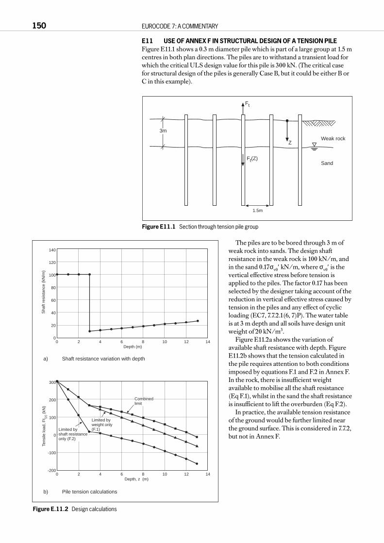
E11 USE OF ANNEX F IN STRUCTURAL DESIGN OF A TENSION PILEFigure E11.1 shows a 0.3 m diameter pile which is part of a large group at 1.5 mcentres in both plan directions. The piles are to withstand a transient load forwhich the critical ULS design value for this pile is 300 kN. (The critical casefor structural design of the piles is generally Case B, but it could be either B orC in this example).
The piles are to be bored through 3 m ofweak rock into sands. The design shaftresistance in the weak rock is 100 kN/m, andin the sand 0.17σv0′ kN/m, where σv0′ is thevertical effective stress before tension isapplied to the piles. The factor 0.17 has beenselected by the designer taking account of thereduction in vertical effective stress caused bytension in the piles and any effect of cyclicloading (EC7, 7.7.2.1(6, 7)P). The water tableis at 3 m depth and all soils have design unitweight of 20 kN/m3.
Figure E11.2a shows the variation ofavailable shaft resistance with depth. FigureE11.2b shows that the tension calculated inthe pile requires attention to both conditionsimposed by equations F.1 and F.2 in Annex F.In the rock, there is insufficient weightavailable to mobilise all the shaft resistance(Eq F.1), whilst in the sand the shaft resistanceis insufficient to lift the overburden (Eq F.2).
In practice, the available tension resistanceof the ground would be further limited nearthe ground surface. This is considered in 7.7.2,but not in Annex F.
150 EUROCODE 7: A COMMENTARY
Z
Ft(Z)
Weak rock
Sand
Ft
1.5m
3m
Figure E11.1 Section through tension pile group
a) Shaft resistance variation with depth
140
120
100
80
60
40
20
00
Sha
ft re
sist
ance
(kN
/m)
2 4 6 8 10 12 14Depth (m)
b) Pile tension calculations
Limited byshaft resistanceonly (F.2)
300
200
100
0
-100
-2000
Tens
ile lo
ad, F
t (z) (
kN)
2 4 6 8 10 12 14Depth, z (m)
Combinedlimit
Limited byweight only(F.1)
Figure E.11.2 Design calculations
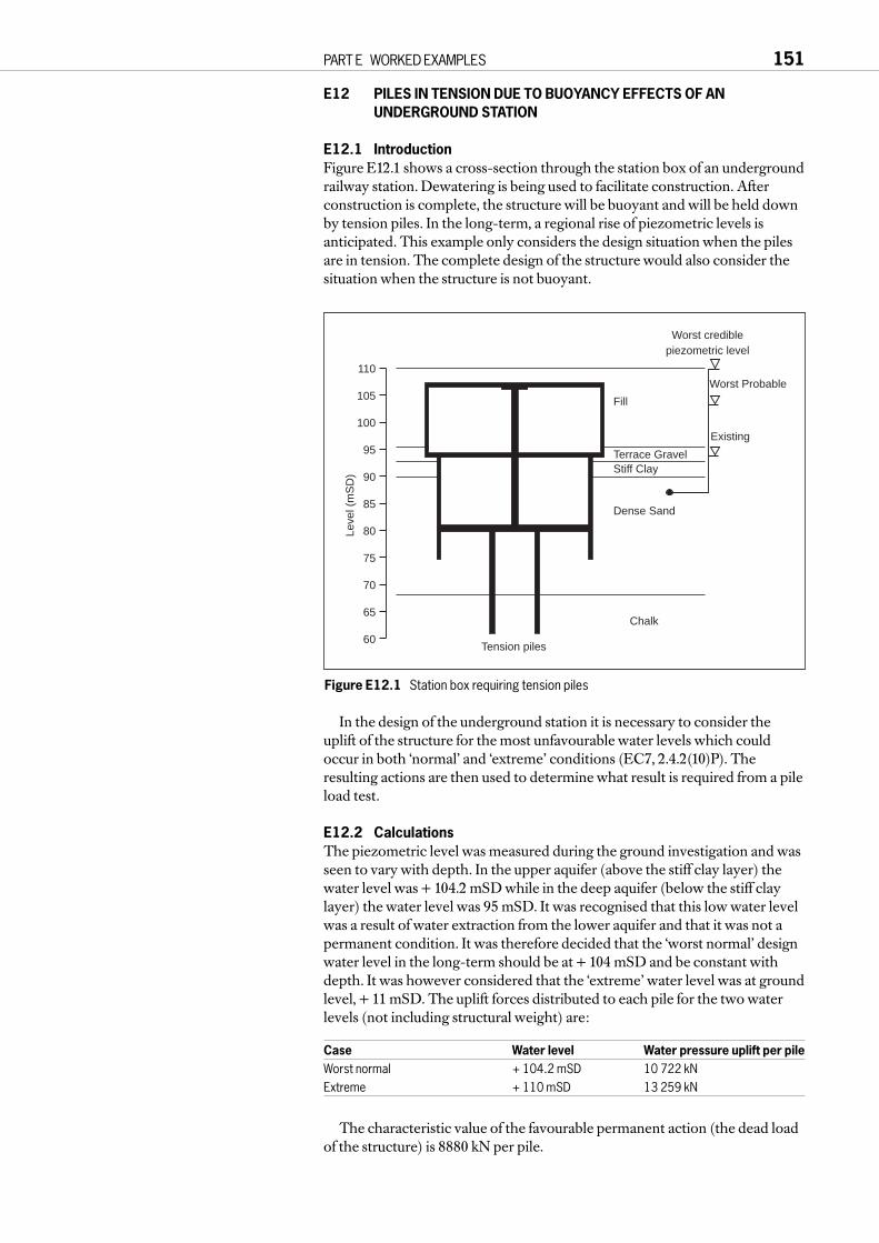
E12 PILES IN TENSION DUE TO BUOYANCY EFFECTS OF ANUNDERGROUND STATION
E12.1 IntroductionFigure E12.1 shows a cross-section through the station box of an undergroundrailway station. Dewatering is being used to facilitate construction. Afterconstruction is complete, the structure will be buoyant and will be held downby tension piles. In the long-term, a regional rise of piezometric levels isanticipated. This example only considers the design situation when the pilesare in tension. The complete design of the structure would also consider thesituation when the structure is not buoyant.
In the design of the underground station it is necessary to consider theuplift of the structure for the most unfavourable water levels which couldoccur in both ‘normal’ and ‘extreme’ conditions (EC7, 2.4.2(10)P). Theresulting actions are then used to determine what result is required from a pileload test.
E12.2 CalculationsThe piezometric level was measured during the ground investigation and wasseen to vary with depth. In the upper aquifer (above the stiff clay layer) thewater level was + 104.2 mSD while in the deep aquifer (below the stiff claylayer) the water level was 95 mSD. It was recognised that this low water levelwas a result of water extraction from the lower aquifer and that it was not apermanent condition. It was therefore decided that the ‘worst normal’ designwater level in the long-term should be at + 104 mSD and be constant withdepth. It was however considered that the ‘extreme’ water level was at groundlevel, + 11 mSD. The uplift forces distributed to each pile for the two waterlevels (not including structural weight) are:
Case Water level Water pressure uplift per pileWorst normal + 104.2 mSD 10 722 kNExtreme + 110 mSD 13 259 kN
The characteristic value of the favourable permanent action (the dead loadof the structure) is 8880 kN per pile.
PART E WORKED EXAMPLES 151
110
105
100
95
90
85
80
75
70
65
60
Leve
l (m
SD
)
Fill
Terrace GravelStiff Clay
Dense Sand
Tension piles
Chalk
Worst crediblepiezometric level
Worst Probable
Existing
Figure E12.1 Station box requiring tension piles

EC7 2.4.2(14)P specifies the load and material factors to be used for thethree cases, A, B and C. Case A is applicable to buoyancy problems only andhas partial factors ≠1 on both ground properties and actions. In principle,Case B has factors ≥ 1 on actions and unit factors on ground properties. CaseC has factors > 1 on ground properties and unit factors on permanent actions.EC1, 1.5.3.3 says that permanent actions include those for which the variation isalways in the same direction (monotonic) until the action attains a certain limit value.In this sense, ground water pressure is considered to be a permanent action.
EC7 2.4.2(10)P requires that for ultimate limit states, design values shallrepresent the most unfavourable values which could occur in extreme circumstances –that is, ‘extreme’ water pressures. For serviceability limit states, less severewater pressures may be used. This paragraph was drafted with Case C loadingin mind and it is unreasonable to multiply worst credible water pressures by afurther factor of 1.35 for the Case B calculations. The same ‘extreme’ waterpressures could have been used as design values for Case B, but as a Case Balternative it is considered that ‘worst normal’ water pressures could betreated as characteristic values, with a factor of 1.35 applied.
Table E12.1 shows the derivation of design tension forces for the piles ineach case. An extra Case A/C has been added; this is discussed below.
Table E12.1 Design tension forces per pileActions (partial factors) Water conditionsPermanent Variable Water Uplift Design Unfavourable Favourable Unfavourable table force tension
(mSD) (kN) (kN)
Case A 1.00 0.95 1.5 110.0 – 13 259 – 4823Case B 1.35 1.00 1.5 104.2 – 10 722 – 5595Case C 1.00 1.00 1.3 110.0 – 13 259 – 4379Case A/C 1.00 0.95 1.5 110.0 – 13 259 – 4823
Case B returns the largest design force to be used in structural design of thetension piles:
Unfavourable + Favourable = Resulting design tensionpermanent water permanent weight1.35 × (– 10 722 kN) + 1.00 × 8880 kN = – 5595 kN (Case B)
It is then necessary to consider the required design tension capacity of thepiles for geotechnical stability. It is assumed here that a single load test will becarried out. The calculations summarised in Table E12.2 show that Case C iscritical, so the tension capacity of pile to be load tested must be at least 10 510 kN.
Table E12.2 Required ultimate measured pile resistanceDesign ξ for 1 pile γm for Resultant factor Resultant tension load test tension piles on load test required load (action) result[a] result test result (kN) (ξ γm) (kN)
Case A – 4823 1.5 1.4[b] 2.11 – 10 176Case B – 5595 1.5 1.0[c] 1.5 – 8 393Case C – 4379 1.5 1.6[d] 2.4 – 10 510Case A/C – 4823 1.5 1.6 2.4 – 11 575
[a] Paragraph 7.7.2.2(2)P, Table 7.3
[b] Section 7 gives values of γm for Case C only. Values for Cases A and B have been derived as follows. Using γm from Paragraph 7.7.2.2(4)P and the ratio of γm on characteristic strength tanφfor Cases A and C in Paragraph 2.4.4(14)P, Table 2.1 the equivalent partial factor is obtained:
γm – Case A = γm – Case C × (γtan φ– Case A / γtan φ– Case C) = 1.6 × (1.1 / 1.25) = 1.41. Note that if the pile capacity was derived from qu the factor would be 1.6 × (1.2 / 1.4) = 1.37
[c] In Paragraph 2.4.4(14)P the partial factor on characteristic soil strength is 1.0 for Case B
[d] Cl 7.7.2.2(4)P
152 EUROCODE 7: A COMMENTARY

In both Tables E12.1 and E12.2 a non-standard case Case A/C has beenincluded. This case takes the worst (most conservative) criteria from Cases Aand C to derive the partial factors to be applied to actions and soil strengths.In the example above the Case A/C required an additional measured pile loadtest resistance of 10% over that required by the most critical of A and C (CaseC here). This could be seen as a useful, but conservative, simplification of theEC7 requirements.
As part of the construction procedure there was the possibility of increasingthe dead weight of the structure by 3000 kN per pile. The design tensionforces under these circumstances are shown in Table E12.3.
Table E12.3 Design tension forces, dead weight increased by 3000 kN per pileActions (partial factors) Water conditionsPermanent Variable Water Uplift Design Unfavourable Favourable Unfavourable table force tension
(mSD) (kN) (kN)
Case A 1.00 0.95 1.5 110.0 – 13259 – 1973Case B 1.35 1.00 1.5 104.2 – 10722 – 2595Case C 1.00 1.00 1.3 110.0 – 13259 – 1379Case A/C 1.00 0.95 1.5 110.0 – 13259 – 1973
Case B again returns the largest structural design capacity for the pileelement with a tension force of – 2595 kN.
Table E12.4 shows that the increase in structural dead weight has changedthe critical case for geotechnical strength of the system. Case A is now seen tobe critical with a required design strength of – 4163 kN some 26% greater thanCase C. The non standard case Case A/C returns a required test pile result of –4735 kN and this is 14% greater than Case A.
Table E12.4 Required ultimate measured pile resistance, dead weight increased by 3000 kN per pile
Design ξ for 1 pile γm for tension Resultant factor Resultant force load test piles[a] on load test required load (action) result result test result
(ξ γm) (kN)
Case A – 1973 1.5 1.4 2.11 – 4163Case B – 2595 1.5 1.0 1.5 – 3892Case C – 1379 1.5 1.6 2.4 – 3310Case A/C – 1973 1.5 1.6 2.4 – 4735
[a] See Table 2 above for derivation of partial factors
If the weight of the structure were increased by a further 1000 kN per pilethen Case B of the standard Cases A, B and C will become critical for bothstructural pile design and requirements on pile load test capacity.
E12.3 CommentFor buoyant structures (structures which require tying down) it is not initiallyobvious which design case will govern the required ultimate pile capacity. Inthe example above a change in dead weight of the structure changed thecritical case from C to A to B. In these examples the non-standard case Case A/C overestimates the required ultimate pile capacity by 10% to 14%.The non-standard case Case A/C is always biased towards the critical casewhether it be Case A or Case C and by doing so results in a single calculationthat is always within the requirements of the code.
PART E WORKED EXAMPLES 153

E13 DESIGN OF A CONCRETE STEM WALL
E13.1 DataFigure E13.1 shows a concrete stem wall supporting sloping ground. Thecharacteristic values of the soil parameters are shown in the figure, togetherwith some fixed dimensions. The design is to find the required length of theheel of the wall, and hence the footing width, B, together with the bendingmoments and shear forces in the wall for structural design. Both ultimate andserviceability limit states must be considered.
E13.2 Ultimate limit statesFor ultimate limit state design, the steps of the calculation are shown in TableE13.1. Both Cases B and C must be considered. Initially, it is assumed thatactive earth pressures may be used for the design, and the implications of thisare reviewed later.
Table E13.1 Calculations for concrete stem wallCase C1 Case C2 Case B1 Case B2
Characteristic φ′ (°) 32.5 32.5 32.5 32.5Factor on tanφ′ 1.25 1.25 1.0 1.0Design φ′ (°) 27.0 27.0 32.5 32.5γsoil (kN/m3) 19 19 19 19γcct (kN/m3) 25 25 25 25Characteristic surcharge p (kPa) 5 5 5 5Factor on surcharge 1.3 1.3 1.1[b] 1.1[b]
Design surcharge p (kPa) 6.5[a] 6.5[a] 5.5[a] 5.5[a]
δ / φ′ active 2/32/3
passive 2/32/3
2/32/3
base 1 1 1 1Design δ° active 20 (= β)[c] 18 20 (= β)[c] 21.3
passive 18 18 21.3 21.3base 27 27 32.5 32.5
Characteristic Ka 0.35 0.35Factor on Ka 1.35 1.35Design Ka
[d] 0.48 0.49 0.47 0.47Design Kp
[d] 4.1 4.1 6.0 6.0Design Nq
[e] 13.2 24.6Design Nc
[e] 24.0 37.0Design Nγ
[e] 12.4 30.1B (m) 5.3 ~ 4.3tan–1 (H / V) for base (°)[f] 22.7 22.2
< 27 √ < 32.5 √Max bending moment in wall (kN m/m) 396 372Max bending moment in toe (kN m/m) 79 78Max bending moment in heel (kN m/m) 365 336
[a] The partial factor on surcharge, taken to be a variable load, is zero when it is beneficial (ie beneficial surcharge is ignored). Cases C1 and B1 consider the overall stability of the wall, so no surcharge is assumed between the wall and the virtual back. Cases C2 and B2 consider the bending moments in the wall, for which surcharge between the wall and virtual back is adverse and so is included
[b] Because the effect of the surcharge will later be factored by 1.35, the input value of this variable action is here factored by 1.5 / 1.35 = 1.1
[c] On the virtual back, δ is set equal to the slope angle β; this is consistent with 8.5.2(2), though this paragraph refers to at rest states. Elsewhere, δ is limited to 2/3 φ′d, in accordance with 8.5.1(4) for ‘precast’ concrete (which really means concrete not cast directly against the soil). The use of δ= β is noted by Clayton et al (1993, p163)
[d] Values taken from Figures G2 and G3 in Annex G
[e] Values calculated using Annex B
[f] H and V are the horizontal and vertical components of the force between the base and the ground
154 EUROCODE 7: A COMMENTARY
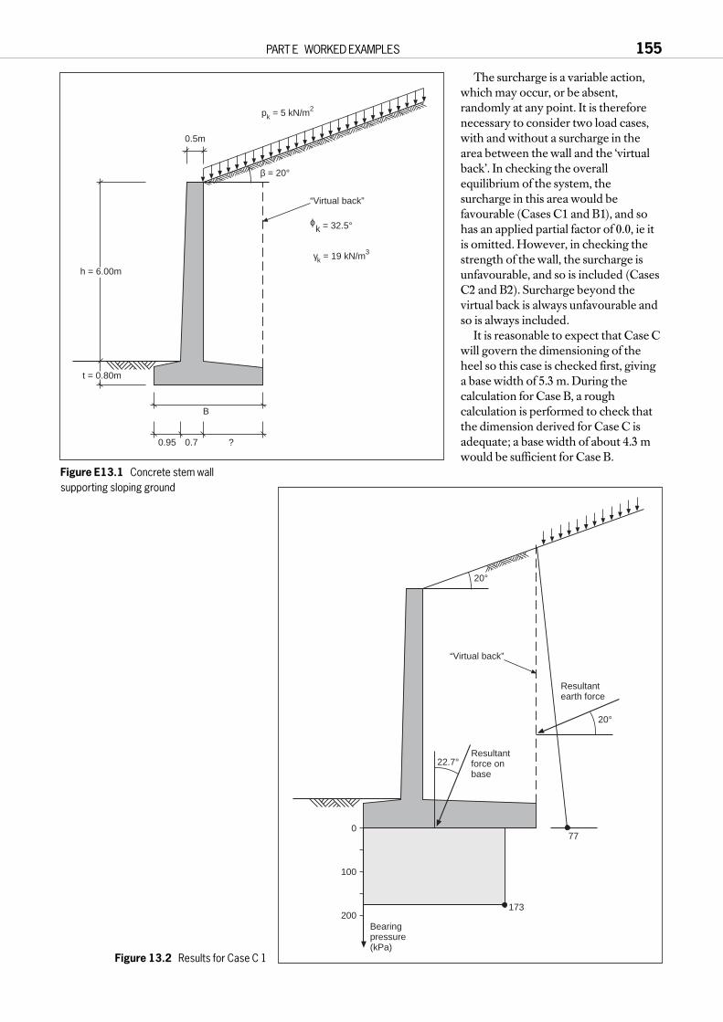
The surcharge is a variable action,which may occur, or be absent,randomly at any point. It is thereforenecessary to consider two load cases,with and without a surcharge in thearea between the wall and the ‘virtualback’. In checking the overallequilibrium of the system, thesurcharge in this area would befavourable (Cases C1 and B1), and sohas an applied partial factor of 0.0, ie itis omitted. However, in checking thestrength of the wall, the surcharge isunfavourable, and so is included (CasesC2 and B2). Surcharge beyond thevirtual back is always unfavourable andso is always included.
It is reasonable to expect that Case Cwill govern the dimensioning of theheel so this case is checked first, givinga base width of 5.3 m. During thecalculation for Case B, a roughcalculation is performed to check thatthe dimension derived for Case C isadequate; a base width of about 4.3 mwould be sufficient for Case B.
PART E WORKED EXAMPLES 155
β = 20°
0.5m
0.95 0.7 ?
B
t = 0.80m
pk = 5 kN/m2
h = 6.00m
“Virtual back”
ϕk = 32.5°
γk = 19 kN/m3
Figure E13.1 Concrete stem wallsupporting sloping ground
20°
“Virtual back”
22.7°
20°
Resultantearth force
Resultantforce onbase
77
173
Bearingpressure(kPa)
0
100
200
Figure 13.2 Results for Case C 1

Each column in the table represents a continuous calculation. Partial factorsare applied to the soil strength (tanφ′ in this case) and to the surcharge load p.Values of the coefficients of earth pressure, K, and of the bearing capacityfactors, N, are then derived directly from EC7 Annexes G and B, using thedesign values of φ′.
The base width B is required to provide equilibrium between the lateralearth pressures and available bearing resistance. This may be achieved byhand calculation or using suitable software; iteration may be required to findthe minimum base width which provides equilibrium. In this case, the Oasysprogram GRETA was used for the wall equilibrium calculations. The shear onthe base, represented by the ratio of forces H / V must be checked to be lessthan the available base friction, δ.
The earth pressures for the critical Case C1 are shown in Figure E13.2. Onthe passive side of the wall, the ground level shown in Figure E13.1 should bethe worst that is foreseeable, allowing for excavation of service trenches, etc.Even then, the upper 0.5 m of passive soil is neglected (EC7, 8.3.2.1(2));although the remaining passive resistance is included, it plays a minor role inthe calculation.
The calculations for Case B are applied to the same wall geometry as Case C, ie that which will finally be built. The method of applying partial
factors in Case B to designs of thistype is slightly uncertain. Theapproach adopted here is to increasethe coefficient of active earthpressure by a factor of 1.35. This isconsidered to be consistent with2.4.2(17), at least in spirit. Because alarger factor of 1.5 should be appliedto the surcharge (a variable action),the surcharge is multiplied at sourceby 1.1 (= 1.5 / 1.35), in theknowledge that the earth pressures itcauses will be factored by 1.35. Thevertical earth pressures and passiveearth pressure have not beenincreased by 1.35. Such a factorseems unreasonable; although itwould affect parts of the Case Bcalculation, it would have very littleeffect on the final design.
Bending moments from Case C2are shown in Figure E13.3. Following6.8(2), the bearing pressure isassumed to be distributed linearlybeneath the base for calculation ofbending moments in the base. Forthis problem, there is little differencebetween the results of the two cases,Case C proving to be critical. Thesebending moments may be takendirectly into Eurocode 2 as ultimatelimit state design values; no furtherfactors are applied to them. Moretypically, for level ground supportedbehind the wall, Case B normallygives the more severe structuralaction effects, especially if waterpressure is present.
156 EUROCODE 7: A COMMENTARY
100
β = 20°
Bending momentin wall
70
500
201
396
365
-79
200
-100
0
M kNm/m
Bearingpressure(kPa)
Bending moment, M(kNm/m)
300
100
300
400
Figure E13.3 Results for Case C2

E13.3 Serviceability limit statesServiceability considerations apply to the displacement of the structure andsurrounding ground, and to the performance of the concrete, especially withregard to cracking.
EC7, 8.7.2 notes that it is often possible to avoid detailed analysis ofdisplacement by noting comparable examples. It would not normally benecessary to calculate the displacement of a wall of this type on a sandfoundation. If it were, the methods of calculating settlements of footings,noted in E5, could be adopted. For economy of effort, the loads on the footingcould be taken from the ULS Case B calculation, but if these lead to a marginalsituation a more accurate calculation of service loads should be undertaken.
EC7, 8.5.1(6) notes that the earth pressures for ultimate and serviceabilitylimit states are, in principle, derived from different calculations. EC7, 8.5.4considers the relationship of earth pressure to movement, and 8.5.5 considerscompaction effects. In considering ‘Structural serviceability limit states’,subclause 8.7.4 notes that all these factors are relevant and that design earthpressures for serviceability limit states will not necessarily be limiting values.EC7 is unable to be more specific because earth pressures existing in theservice state are very dependent on individual circumstances.
A minimum earth pressure sometimes used for the serviceability check ofthis type of wall may be obtained using a coefficient of earth pressure, KSLS,given by:KSLS = 1/2(Ka + Knc) where Ka is the coefficient of active pressure and Knc = (1 – sinφ′). For slopingground, Knc would logically be replaced by Knc (1 + sinβ), as in 8.5.2(2). Whereit is known that heavy compaction will be used, a larger value should beadopted, however. (Currently, for design of backfilled retaining walls andbridge abutments on the trunk road network in the United Kingdom,BD30/87 has much more severe requirements – see Carder (1998).)
For this calculation, characteristic values of φ′ should be used, so:KSLS = 1/2(Ka + Knc,k).
Typically, if δ = 2/3 φ′ is used in deriving Ka, this gives a value for KSLSroughly equal to the value used for ULS design, which cannot be less than1.35 Kak, used in Case B. So it is likely that serviceability will dominate thestructural design. This situation may be compared with that of BS 8002, which proposes that both SLS and ULS design of the structural sectionsshould be based on the same earth pressures. In this problem, they would beequivalent to about 1.25 Kak, slightly smaller than the value of KSLS suggestedhere. Using either code, structural designers may prefer to carry out the ULSdesign for a larger bending moment in order to give simple SLS calculations,as discussed in C8.6.6.
PART E WORKED EXAMPLES 157

E14 DESIGN OF A CANTILEVER SHEET PILE WALL
E14.1 Data and methodFigure E14.1 shows Example B2 taken from CIRIA Report 104. It requires thedesign of a cantilever sheet pile wall in a single soil, with differential waterpressure across the wall and no surcharge behind the wall. It is consideredthat the ‘moderately conservative’ values of CIRIA 104 are equivalent tocharacteristic values for the soil parameters. Only the permanent worksdesign will be considered here. EC7 does not provide specific requirementsfor temporary works; this point is considered in B6 and C2.4.2(14)P.
EC7, 8.3.2.1 requires that an ‘overdig’ allowance shall be made for wallswhich rely on passive resistance, without distinction between temporary andpermanent situations. This is discussed in C8.3.2.1. The overdig allowance willbe applied in this example.
Because the wall is unpropped, the earth pressure distribution relevant toultimate limit states in both the ground and the structure is of the simple formshown in Figure E14.2, which shows the design conditions and earthpressures calculated for EC7 Case C. Hand calculations or a computerprogram may be used to find the wall length which gives equilibrium.
158 EUROCODE 7: A COMMENTARY
1m
1m
h = 4m
γ = 20 kN/m3
γ = 10 kN/m3
φ’= 25° (moderatelyconservative)
Figure E14.1 Cantilever wall example (CIRIA Report 104, Example B2)
0-1.00
-4.40-5.00
10% “Overdig”
Effective stress
Water pressure
φ’d = 20.5°
Red
uced
leve
l (m
OD
)
4
0
-4
-8
-12
-16
Distance from wall (m)-4 -2 0 2 4
Pressures (kN/m2)400 200 0 400200
Top (0)
Toe (-14.42)
Figure E14.2 Cantilever sheet pile wall: Case C conditions and earth pressures

E14.2 Comparative calculationsIn CIRIA Report 104, the calculated wall length for simplified handcalculations was 14.6 m, and this was increased to 16.6 m to allow for thesimplifications made. Table E14.1, Column 1 shows the results of a calculationbased on the same principles, but carried out using the Oasys programSTAWAL, so avoiding the need for simplifications in the equilibriumassumptions. The resulting wall length is 15.2 m, lying between the two valuesof CIRIA 104. The bending moment derived from this calculation,822 kNm/m, is disregarded in the CIRIA method. Column 2 shows theresults of CIRIA’s bending moments calculation, in which unit factors areapplied to soil strength, but the resulting bending moment is increased by afactor of 1.5. The bending moment derived for ULS design of the sheet pile is455 kNm/m.
Table E14.1 Results for a cantilever sheet pile wallCase CIRIA CIRIA CIRIA EC7 EC7 BS 8002
Fs = 1.5 F = 1 F = 1 Case C Case Coverdig overdig no overdig
Col 1 Col 2 Col 3 Col 4 Col 5 Col 6
γφ = Fs 1.5 1.0 1.0 1.25 1.25 1.2φ′d 17.3° 25° 25° 20.5° 20.5° 21.2°δ / φactive 2/3
2/32/3
2/32/3
3/4
δ / φpassive 1/21/2
1/22/3
2/33/4
Ka 0.49 0.36 0.36 0.43 0.43 0.41Kp 2.28 3.47 3.47 2.8 2.8 3.1Overdig (m) 0 0 0.4 0.4 0 0.5Surcharge (kPa) 0 0 0 0 0 10Data CANTB6A CANTB5 CANTB3 CANTB4 CANTB8
Length (m) 15.2 (10.0) 11.95 14.42 12.28 14.60BM (kNm/m) (822) 303 511 808 507 959
(= 303 × 1.7)
BM factor 1.5 1.5 ?? 1.0 1.0 1.0ULS BM (kNm/m) (822) 455 767 ?? 808 507 959Factor α (Zel / Zpl) 1 0.8 0.8 ??ULS BM for Zel (822) 455 646 406 ??
Notes: This example is based on CIRIA 104 example B2, page 107
Figures shown in brackets are not used in the design methods
All calculations by Oasys STAWAL
Column 4 shows the results of a Case C calculation for EC7. The wall isslightly shorter than derived from CIRIA 104, but the bending moment is verymuch larger at 808 kNm/m. Comparison of columns 4 and 5 shows that muchof the reason for this larger bending moment is EC7’s requirement that thesurface of the passive soil be considered to be 0.4 m (10% of the supportedheight) lower than is intended. Without this allowance, Column 5 shows thatthe bending moment would be 507 kNm/m, 11% bigger than for CIRIA 104,but the overdig causes a further 59% increase in bending moment. It isalarming to realise that a small overdig (0.4 m) places such a large demand onthe structural system! This is why a specific allowance is made for this effect inEC7 and in BS 8002.
For comparison, a calculation to BS 8002 is shown in Column 6. Thisrequires a slightly larger allowance for overdig and also imposes a minimumsurcharge of 10 kPa. It therefore gives an even higher bending moment,despite the fact that its factor on soil strength (1.2) is less than that of EC7(1.25), and δ / φ is taken as 3/4, compared with 2/3 for steel sheet piling in EC7 (8.5.1(4)).
PART E WORKED EXAMPLES 159
E14.3 Required bending resistanceDesign methods cannot be compared, however, simply on the basis of thebending moments derived. The design of a sheet pile wall is not completeuntil the steel section has been chosen, and for this purpose, it is necessary toconsider the structural codes with which EC7, CIRIA 104, etc are to be used.
EC7 is to be used as part of the Eurocode system with Eurocode 3 (ENV1993). EC3 Part 5 considers the design of steel sheet piles and is based onconcepts of plastic design. For robust sections, which will deform in a ductilemanner, EC3-5 allows the use of plastic moments of resistance. Values forthese are still somewhat uncertain (early 1998), but they probably exceed theelastic moments of resistance used by previous codes by about 20%, typically.If this proves to be the case, it will roughly halve the difference between thestructural demands of EC7 and CIRIA 104. In fact, if overdig weredisregarded, EC7 would require a less strong sheet pile than does CIRIA 104.
E14.4 DiscussionThe requirement that overdig be specifically allowed for was discussed inC8.3.2.1. This example shows that this requirement, which is common to EC7and BS 8002, has an important effect and should only be discounted inexceptional circumstances.
It is recognised, however, that many designs to CIRIA Report 104 haveperformed satisfactorily, despite no allowance for overdig. The analysis abovesuggests that this might be expected. CIRIA 104 designs generally give longerwalls than required by the newer codes, but with lower design bendingmoments. However, the use of elastic moments of resistance for the sectiondesign to CIRIA 104 probably ensures that the wall has sufficient momentcapacity. The Eurocode system will allow plastic moments of resistance.Overall, the Eurocodes probably give a better understanding of thecompatibility of length and strength in the wall design.
It is noted that, in practice, the choice of steel section is often governed bydrivability, which may require a stronger section than that needed for bending moments.
160 EUROCODE 7: A COMMENTARY

E15 DESIGN OF A PROPPED EMBEDDED WALL
E15.1 Description of problemA propped, embedded wall is to be designed for the situation shown in Figure E15.1. In this example, a sheet pile wall will be designed, with the aimof minimising the steel section. Deflection will be considered, but it will notgovern the design. Water pressure is equalised, approximately, at the bottomof the wall, with linear distributions on either side of the wall.
A brief account of a suitable set of calculations for this design will first bepresented. Following this, a more detailed description of comparativecalculations carried out for a slight variant on this problem will be given.
Attention has been concentrated on Frodingham (Z) sections in order toavoid the long-standing dispute about shear transfer in the clutches of Larssen(U) sections. This is noted in EC3-5, but is at present left to national decision,to be stated in the NAD of EC3.
E15.2 Basic set of calculations
E15.2.1 Parameters and factorsFor ULS design, the partial factorsgiven in EC7, Table 2.1 will be used.If the sheet pile wall had only atemporary purpose, and if theconsequences of failure would be lessthan for a typical design of permanentworks, it is arguable that smallerpartial factors could be used inaccordance with 2.4.2(14)P (see C2.4.2(14)P). CIRIA Report 104, Table 5,could be used to form a view on theproportion by which factors may bereduced for the temporary case.
Figure E15.1 shows thecharacteristic values of the groundparameters and surcharge. Thedesign values for ULS Case C areshown in Figure E15.2. The depth of
PART E WORKED EXAMPLES 161
Characteristic Values
0
-1m
-5.0m
10 kPa Surcharge
φ'k = 35˚ c' = 0
φ'k = 24˚ c'k = 5 kPa φ'k = 24˚ c' = 0
-4.0m
E = 40 MPa
E = 20 MPa
E = 30 MPa
Gravel
Stiff clay Stiff clay
Figure E15.1 Propped embedded wall: characteristic conditions
0
-1m
-5.4m
13 kPa Surcharge
φ'd = 19.6˚ c'd = 3.1 kPa
φ'd = 19.6˚ c' = 0
Case C Design Values
φ'd = 29.3˚ c' = 0
-4m
E = 40 MPa
E = 20 MPa
E = 30 MPa
Figure E15.2 Propped embedded wall: Case C design conditions

excavation is increased by 10%, as required by 8.3.2.1(2), and a partial factor of[1.3] is applied to the surcharge (a variable action).
For ULS Case B, the ground parameter values are unchanged from those inFigure E15.1, but the depth of excavation is increased as in Figure E15.2. Thefactor on permanent actions, [1.35], is applied as a model factor, as suggestedby 2.4.2(17), since it would be unreasonable to apply it directly to waterpressures. The effect of the surcharge (a variable action) is to be increased by afactor of [1.5]; this is achieved by multiplying it by 1.1 (~ 1.5 / 1.35) at source,in the knowledge that its effects on bending moments will be increased by afurther factor of 1.35.
E15.2.2 Quick, conservative ULS designThe calculations required for a quick, conservative approach are summarisedin Table E15.1. Both Case B and Case C calculations are undertaken, usingearth pressure diagrams of the type shown in Figure E15.3. In this case, Case Cis found to govern in all respects: length, bending moment, prop force andshear force. For prop and shear force, the difference between the two cases issmall, and in some designs Case B is found to govern. Selection of the sheet
162 EUROCODE 7: A COMMENTARY
0
-1.00
-5.40
189.5 kN/m
Red
uced
leve
l (m
OD
)
12
8
4
0
-4
-8
-12
-16
-20
-24
Distance from wall (m)-4 -2 0 2 4
Pressures (kN/m2)100 50 0 10050
Top (0)
Toe (-12.67)
-6
150
Effective stress
Water pressure
Figure E15.3 Simple earth pressure distribution

pile section and design of the prop could now proceed using the worst of thevalues in Table E15.1 as ULS design values for EC3. If needed, a separateanalysis for SLS could be carried out as discussed below or by other means.
This approach is likely to lead to larger bending moments than otherconventional approaches. However, in many situations the section selectedfor sheet pile walls has plenty in reserve for bending, often because it is chosenfor drivability, so there may be no penalty incurred by larger calculatedbending moments.
PART E WORKED EXAMPLES 163
Table E15.1 Quick, conservative calculations for a propped embedded wall
Case C Case BColumn 1 Column 2
Dig level (m) – Stage 2 5.4 5.4Sand and gravel
Characteristic φ′ (°) 35 35γφ 1.25 1.0Design φ′ (°) 29.3 35δ / φ′ active 2/3
2/3
passive 0 0Ka 0.29 0.23Kp 2.9
ClayCharacteristic φ′ (°) 24 24γφ 1.25 1.0Design φ′ (°) 19.6 24Characteristic c′ 5 5(active only – kPa)γc 1.6 1Design c′ (active – kPa) 3.1 5δ / φ′ active 2/3
2/3
passive 2/32/3
Ka 0.43 0.36Kp 2.6 3.6a′ / c′ 1/2
1/2
Kac 1.61 1.47Kpc 3.95
γQ 1.3 1.1Computer program STAWAL STAWALData file JB3C1B JB3B1BWall length (m) 12.7 10.3Bending moments (kNm/m)
Maximum calculated 531 312ULS factor γF 1 1.35ULS design 531 421SLS design
Prop force (kN/m)Maximum calculated 190 129ULS factor γF 1 1.35ULS design 190 174
Max shear force (kN/m)Maximum calculated 183 124ULS factor γF 1 1.35ULS design 183 167
Table E15.2 Basic design of a propped embedded wall
Case C Case C Case B SLSColumn 1 Column 2 Column 3 Column 4
Dig level (m) – Stage 2 5.4 5.4 5.4 5.0Sand and gravel
Characteristic φ′ (°) 35 35 35 35γφ 1.25 1.25 1.0 1Design φ′ (°) 29.3 29.3 35 35d / φ′ active _ _ _ _
passive 0 0 0 0Ka 0.29 0.29 0.23 0.23Kp 2.9 1.0 3.6 1.0
ClayCharacteristic φ′ (°) 24 24 24 24γφ 1.25 1.25 1.0 1Design φ′ (°) 19.6 19.6 24 24Characteristic c′ 5 5 5 5(active only - kPa)γc 1.6 1.6 1 1Design c′ (active – kPa) 3.1 3.1 5 5δ / φ′ active 2/3
2/32/3
2/3
passive 2/32/3
2/32/3
Ka 0.43 0.43 0.36 0.36Kp 2.6 2.6 3.6 3.6a′ / c′ 1/2
1/21/2
1/2
Kac 1.61 1.61 1.47 1.47Kpc 3.95 3.953
γQ 1.3 1.3 1.1 1.0Computer program STAWAL FREW FREW FREWData file JB3C1B JB3C9B JB3B9B JB3S5Wall length (m) 12.67 11.3[a] 11.3[a] 11.3[a]
Bending moments (kNm/m)Maximum calculated 531 424 227 119ULS factor γF 1 1.35ULS design 424 306SLS design 119
Prop force (kN/m)Maximum calculated 190 238 165 109ULS factor γF 1 1.35ULS design 238 223
Max shear force (kN/m)Maximum calculated 183 213 140 109ULS factor γF 1 1.35ULS design 213 189
[a] Given as data – not calculated by the program

E15.3 More refined calculationEC7 requires that the design must demonstrate that equilibrium can beachieved using the design actions and the design strengths, with compatibilityof deformations (8.6.1(4)P and 2.1(9)). It does not specify, however, aparticular distribution of earth pressures to be used for embedded walls. Forthe ULS calculations, there is no limit to the magnitude of displacementsallowed, unless they would cause a ULS in an adjacent structure. For proppedwalls, the computed bending moments and prop forces are very dependenton the assumed distribution of earth pressures. The approach adopted here istherefore to make a rough assessment of the required length of the wall, thento use a more refined analysis to verify this and to find the bending moments,which determine the steel section, and the prop forces.
An estimate of the wall length is first determined using the Case Cparameters with simple equilibrium calculations, adopting the earth pressuredistribution shown in Figure E15.3. This calculation shows that a wall lengthof 12.7 m will be adequate, though more refined calculation might justify ashorter length. On the basis of judgement, a length of 11.3 m is then used inchecks for both Cases B and C, using the Oasys program FREW; this allowsfor redistribution of earth pressure on a basis compatible with deformations.In order to do this calculation, it is necessary to specify stiffness parametersfor both the ground and the wall. The ground stiffness has been characterisedby Young’s moduli, E, as shown in Figure E15.2 and the wall by a bendingstiffness EI = 50158 kNm2/m, corresponding to a Frodingham 3N section.The final results, for ULS design, are not very sensitive to these stiffnesses.
Figures E15.4a and b show the computed earth pressure distributions andbending moments for Case C, at two stages of the excavation. (Note that thescales for bending moment are different in these two plots.) Theredistribution of earth pressure, with pressure attracted towards the prop inthe second diagram, is clearly evident. It should be remembered that thesediagrams are for ultimate limit states in which deformations are large. Themaximum computed deflection of the wall in Case C is 137 mm; there is nolimit on this figure for the ULS calculation.
The FREW calculations in Table E15.2 show that equilibrium can beachieved for both cases B and C with a maximum ULS design bendingmoment of 424 kNm/m. As is normal for this type of wall, Case C gives thelarger bending moment. The ULS design prop force is 238 kN/m; this is alsodetermined by Case C in this case, but in others Case B sometimes leads tothe larger prop force.
The ULS design bending moment may be resisted using a Frodingham 3Nsheet pile, which has a ULS capacity of about 590 kNm/m. This sectiontherefore satisfies the design requirements (590 > 424) It may be that designto EC3-5, using the plastic capacity of the sheet piles, might make it possibleto adopt a lighter section. The props should be designed to Eurocode 3, usingthe design ULS force of 238 kN/m.
E15.4 SLS checkTable E15.2 also shows the results of a serviceability computation by FREW.For this, all partial factors are unity and there is no allowance for ‘overdig’. Thelength of wall gives it fixity at the base, as can be seen in Figure E15.5, and theSLS bending moment is 119 kNm/m, only 28% of the design ULS value.Calculations of this type, if done at all, would normally only be used to assessthe maximum SLS deflection, which was calculated as 29 mm. This valueshould be used in assessing effects on the serviceability of adjacent structuresor services.
164 EUROCODE 7: A COMMENTARY

PART E WORKED EXAMPLES 165
Red
uced
leve
l (m
OD
)
-4
-8
-12
-16
-20
Bending moment (kNm/m)
0
0.00
-20.00
-50.0 50.0
Pressures (kN/m2)250.0 0 250.0
-11.26
-1.50
0.00
-1.00
a) Partly excavated
b) Fully excavated
Red
uced
leve
l (m
OD
)
-4
-8
-12
-16
-20
Bending moment (kNm/m)0
0.00
-20.00
-500.0 500.0
Pressures (kN/m2)250.0 0 250.0
-11.26
-5.40
0.00
-1.00 237.9 kN/m
P eff.P.w.p.ActivePassiveB.M
P eff.P.w.p.ActivePassiveB.M
Figure E15.4 Earth pressure distributions from FREW Case C analysis

E15.5 CommentsIt is of interest to compare the results of the FREW analyses with the simplercalculations represented by Column 1 of Table E15.1, and represented byFigure E15.3. These give a maximum bending moment which is 26% higherthan adopted in the design, with a prop force 20% lower. In general, it wouldbe safe to design the sheet pile section using these simpler calculations, butthe prop force would be underestimated. Experience may show that thesesimpler Case C calculations could be used, provided an additional modelfactor is applied to the prop force, in accordance with the approach of2.4.1(5)P. This example suggests that the factor might be about 1.25 (= 238 / 190).
In German practice for design of sheet pile walls, a set of conventional ruleshas been developed for redistribution of earth pressures. Reference may bemade to Grundbau-Taschenbuch (1992) and EAB (1994).
E15.6 Other checks required by EC7
E15.6.1 Overall equilibriumOverall equilibrium should be checked in accordance with 8.2(1)P. Thisdepends on the form of the prop or anchor, and could involve slip surfacespassing behind anchorages, for example, or cutting through the fixed anchor length.
E15.6.2 Vertical equilibriumVertical equilibrium of the sheet pile should be checked in the ultimate limitstate (EC7, 8.6.5). Small inequalities between the downward force from theretained soil and the upward force from the passive soil can be taken out at thebase of the wall.
166 EUROCODE 7: A COMMENTARY
Red
uced
leve
l (m
OD
)
-4
-8
-12
-16
-20
Displacement (mm)
0
0.00
-20.00
-50.0 50.0
Pressures (kN/m2)250.0 0 250.0
-11.26
-5.00
0.00
-1.00 129.2 kN/m
P eff.P.w.p.ActivePassiveDisp.
Figure E15.5 Results from FREW SLS analysis

If inclined anchors were used, or if the wall carried a vertical load, thischeck would be more critical and could lead to revision of the values of δ / φ′.If the wall was a concrete diaphragm wall, and δ / φ′ = 1 was used, as allowedby the code, vertical equilibrium might again be critical.
In many cases, the risk of a further iteration of calculation could be avoidedby using δ / φ′ = 1/2 in the retained soil but δ / φ′ = 2/3 in the passive soil. Thiswas recommended by Terzaghi (1954), though British practice has tended tointerchange these values.
E15.6.3 DrivabilityEC7, 8.4(4) notes that sheet piles must have a sufficiently stiff section to bedrivable. Table 1.6 of the ‘British Steel Piling Handbook’ (1997) recommendsthat 3N sections should not be driven more than 18 m, so this is acceptable here.
The 3N section has an elastic section modulus of 1688 cm3/m. Table 1 of‘Sheet piling in permanent land based structures’ (British Steel General Steels,1989) suggests a minimum modulus of 2300 cm3/m to penetrate soil withSPT > 40 for grade 43 steel, and SPT > 45 for grade 50 steel. Hence a biggersection may be required if the upper granular layer is very dense.
In practice, the choice of steel section is often governed by drivability, inwhich case concerns about calculation of bending moment become academic.
E15.7 Detailed comparative study
E15.7.1 Design problemIn this section, an extensive series of comparative calculations is presented.These would not be needed in a design process, but are included here tofacilitate comparisons between results from EC7 and those from otherdocuments and methods. The problem addressed is as shown in FiguresE15.1, E15.2 and E15.3, with two aspects differing from the calculations in theprevious section:a water pressures are not equalised at the bottom of the wall, but are assumed
hydrostatic on both sides, andb the bending stiffness used in the FREW analyses is 30 000 kNm2/m,
roughly equivalent to a Frodingham 2N section.
A complete set of results is shown in Table E15.3. The calculations will bereferred to by column numbers in this table.
E15.7.2 EC7 calculationsColumns 1 and 2 represent simple calculations similar to those in E15.2 above,with earth pressure diagrams of the type shown in Figure E15.1. Using thesecalculations alone, the required wall length would be 11.8 m and the ULSdesign bending moment 465 kNm/m. Column 3 uses a similar simplecalculation for SLS, should an SLS bending moment be required. (If a muchstiffer wall were to be used, such as a concrete diaphragm wall, this SLScomputation would be questionable because it assumes that the retained soilwill have reached active pressures in the serviceability state.) Column 4 is basedon a FREW calculation for the wall length obtained in Column 1, and showsthat the working bending moment for a very fl exible wall (EI = 30 000 kNm2/m)is likely to be about 30% of the ULS design moment in Column 1.
Columns 10, 11 and 12 show three alternative computations for Case C,using the computer programs FREW, SAFE and SPOOKS. All three of these programs compute the redistribution of stresses in the retained material, but in quite different ways: FREW is a pseudo-finite elementapproach; SAFE is a standard finite element analysis using elastic-Mohr-Coulomb material; SPOOKS uses the plasticity approach to sheet pile design proposed by Brinch Hansen (1953) and Mortensen (1983). Thesesolutions give wall lengths of 11.3 to 11.5 m and bending moments in the range318 to 376 kNm/m.
PART E WORKED EXAMPLES 167

Table E15.3 Comparative results for a propped embedded wallCase C Case B SLS SLS Fp=2 Fs=1.2, SLS Case C Case C Case C Case C Case C Case C
STAWAL FREW 1.5 STAWAL Rowe SAFE SPOOKS
Col 1 Col 2 Col 3 Col 4 Col 5 Col 6 Col 7 Col 8 Col 9 Col 10 Col 11 Col 12 Col 13
Dig level (m) – Stage 2 5.4 5.4 5.0 5.0 5.0 5.0 5.0 5.4 5.0 5.4 5.4 5.4 5.0
Sand and gravel
Characteristic φ′ (°) 35 35 35 35 35 35 35 35 35 35 35 35 35
γφ 1.25 1 1 1 1 1.2 1 1.25 1.25 1.25 1.25 1.25 1.25
Design φ′ (°) 29.3 35 35 35 35 30.3 35 29.3 29.3 29.3 29.3 29.3 29.3
δ / φ′ active 2/32/3
2/32/3
2/32/3
2/32/3
2/32/3
2/3 max 2/32/3
passive 0 0 0 0 0 0 0 0 0 0 2/3 max 0 0
Ka .29 0.23 0.23 0.23 0.23 0.28 0.23 0.29 0.29 0.29 0.29 0.29
Kp 2.9 3.6 3.6 1.0 1.8 3.0 3.6 2.9 2.9 1.0 2.9 1.0
Clay
Characteristic φ′ (°) 24 24 24 24 24 24 24 24 24 24 24 24 24
γφ 1.25 1 1 1 1 1.5 1 1.25 1.25 1.25 1.25 1.25 1.25
Design φ′ (°) 19.6 24 24 24 24 16.5 24 19.6 19.6 19.6 19.6 19.6 19.6
Characteristic c′ 5 5 5 5 5 5 5 5 5 5 5 5 5
(active only – kPa)
γc 1.6 1 1 1 1 1 1 1.6 1.6 1.6 1.6 1.6 1.6
Design c′ (active – kPa) 3.1 5 5 5 5 3.33 5 3.1 3.1 3.1 3.1 3.1 3.1
δ / φ′ active 2/32/3
2/32/3
2/32/3
2/32/3
2/32/3
2/3 max 2/32/3
passive 2/32/3
2/32/3
1/21/2
1/22/3
2/32/3
2/3 max 2/32/3
Ka 0.43 0.36 0.36 0.36 0.36 0.50 0.36 0.43 0.43 0.43 0.43 0.43
Kp 2.6 3.6 3.6 3.6 2.0 2.2 3.4 2.6 2.6 2.6 2.6 2.6
a′ / c′ 1/21/2
1/21/2
1/21/2
1/21/2
1/21/2
1/21/2
1/2
Kac 1.61 1.47 1.47 1.47 1.47 1.73 1.47 1.61 1.61 1.61 1.61 1.61
Kpc 3.95 4.60 4.60 4.6 2.6 3.6 4.5 3.95 3.95 3.95 3.95 3.95
γQ 1.3 1.1 1.0 1.0 1.0 1.0 1.0 1.3 1.3 1.3 1.3 1.3 1.3
Computer program STAWAL STAWAL STAWAL FREW STAWAL STAWAL STAWAL Rowe STAWAL FREW SAFE SPOOKS FREW
Data file JB3C1A JB3B1 JB3S3 JB3S5 JB3FPC JB3FSB JB3S4 STAWAL JB3C7A JB3C2B JB3C9 JB3C6B
JB3S4 JB3S4 JB3C1A
Wall length (m) 11.8 9.6 (8.9) 11.4[a] 12.9 12.5 (9.1) 11.8 10.9 11.3[a] 11.3[a] 11.5 11.3[a]
Bending moments (kNm/m)
Maximum calculated 465 275 215 135 (436) (482) 224 465 366 318 350 376 273
ULS factor γF 1 1.35 1.5 1 1 1 1 1
ULS design 465 371 336 336 336 349/314 366 318 350 376 273
SLS design 215 135 224 224 224
Prop force (kN/m)
Maximum calculated 175 120 103 129 (158) (176) 105 152 194 236 191 179
ULS factor γF 1 1.35 2 1 1 1 1 1
ULS design 175 162 210 210 210 152 194 236 191 179
Max shear force (kN/m)
Maximum calculated 169 115 98 107 (153) (170) 101 145 169 180 154
ULS factor γF 1 1.35 1.5 1 1 1 1
ULS design 169 155 152 152 152 145 169 180 154
[a] Given as data – not calculated by the program
168 EUROCODE 7: A COMMENTARY

E15.7.3 CIRIA 104 calculationsColumn 5 shows a traditional calculation, noted by CIRIA Report 104, inwhich a factor of safety of 2 on passive effective stress used. For this, a longerlength is required, 12.9 m, and the calculated bending moment is 436 kNm/m.However, this bending moment would traditionally have been disregarded.
Column 6 shows the calculation required by CIRIA Report 104’s ‘strengthfactor method’, with factors of 1.2 on tanφ′ in the sand and gravel, and 1.5 inthe clay. The calculated length is 12.5 m and the bending moment 482 kNm/m.CIRIA 104 recommends that this bending moment be disregarded and thevalue calculated in Column 7 substituted. Here, soil parameters areunfactored, but a factor of 1.5 is applied to bending moment and 2.0 to propforce. These factored results could be used with the wall lengths obtained inColumns 5 or 6. The Column 7 calculation is very similar to Column 3, exceptthat CIRIA 104 limits δ / φ′ in the passive soil to 1/2, whereas EC7 allows 2/3.The resulting ULS design bending moment from this CIRIA 104 approach is336 kNm/m.
E15.7.4 Rowe’s methodRowe (1952, 1955) recognised that the type of calculation in Column 5 gavelarge bending moments, and so derived ‘working’ values by applying factorsto allow for flexibility to the moment from Fp = 2 calculations. The method isvery rational, but ingenuity is required to apply it within a limit stateframework, especially to a problem involving clays.
Rowe’s factor rt allows for the beneficial effect of higher pressures abovethe prop and correspondingly lower active pressures below. It seemsreasonable to apply this to the calculated Case C bending moment. Its value in this case is about 0.75, reducing the bending moment to 431 × 0.75 = 323 kNm/m.
Rowe’s factor rd allows for the beneficial effect, in the working state, of thelength of wall greater than required by the working soil strengths. Its valuehere is about 0.6 and it could be used to derive a working bending moment of323 × 0.6 = 194 kNm/m. Following CIRIA Report 104, this could bemultiplied by 1.5 to derive an alternative ULS design bending moment of 194 × 1.5 = 290 kNm/m.
E15.7.5 Significance of ‘overdig’Columns 9 and 13 are used to show how big is the effect of the ‘overdig’allowance of 0.4m. Comparing Columns 1 and 10, the effect is 29% and 16%,respectively, depending on the type of calculation used.
E15.7.6 DiscussionFor this situation, traditional calculations lead to a wall length of about 12.7 m(Columns 5 and 6) with a design ULS bending moment of about 336 kNm/m(Columns 7 and 8). EC7 design allows a shorter wall, 11.8 m long or, withmore refined calculation, down to 11.3 m or less. In its simplest form, the EC7calculation is likely to lead to higher bending moments (Column 1), with theconsequent need for a stronger wall section in some cases. However, withinthe design requirements of EC7 the bending moments can be reduced to besimilar to traditional values (Columns 8, 10, 11 and 12). The selection of steelsection will be dependent on EC3-5; although this allows the plastic momentof resistance to be used for more robust steel sections, but the effect may befairly small for the relatively light sections used here. The section selected foran EC7 design following Columns 8, 10, 11 or 12 may therefore be similar tothat of a CIRIA 104 design.
The prop forces computed for the EC7 design (Columns 10 to 12) aresimilar to that required by CIRIA 104, including its requirement of a factor ofsafety of 2 on the initially calculated value (Column 7). The simplercalculation to EC7 in Column 1 gives a lower ULS design prop force; whilstthis could be safe, given the higher requirement for bending strength of the
PART E WORKED EXAMPLES 169

wall, there may be danger in lowering the design force in props, which maycreate instability by buckling.
The conventional methods, reported by CIRIA Report 104, have beencriticised for giving walls with incompatible length and strength. Theirbending capacity is not sufficient to use their full length if it should prove to beneeded. This results from the use of two independent calculations for lengthand strength. The EC7 design requires that, however the calculations areperformed in detail, the resulting wall must be both long enough and strongenough to survive in the applied ULS conditions. The net result will be wallswhich are a little shorter, but probably of similar strength to those ofconventional British practice.
It may be that, with further trials and experience, it will be possible to showthat simpler calculations, such as those of CIRIA Report 104, always lead todesigns which satisfy the requirements of EC7, used with EC3-5.
In the simpler approach presented in E15.2, the design used the equivalentof Column 1, only as an initial indication of length, with Column 10 to validatea shorter length and find the design bending moment.
E15.7.7 International comparisonFigure E15.6 shows results ofcalculations submitted to theEurocode committeeCEN/TC250/SC7 for this design by19 engineers representing most ofthe European countries. Most of thederived lengths and ULS designbending moments lie in a smallrange, and it is likely that the fewoutliers represent clear mistakes ormisunderstandings. The lengthobtained in Column 10 of Table E15.3is marked ‘L’ and can be seen to betypical of the designs proposed. Thebending moment from Column 10 ismarked ‘H’, noting that this was forhydrostatic water pressures eitherside of the sheet pile. The value fromTable E15.2, Column 2, for whichwater pressures were equalised at thebottom of the sheet pile, is marked‘E’. Both points E and H are withinthe range obtained by otherEuropean engineers; theirassumptions about pore pressuredistribution are not known.
170 EUROCODE 7: A COMMENTARY
a) Length comparison
b) Bending moment comparison
20
18
16
14
12
10
8
6
4
2
00 5 10 15 20
2000
1800
1600
1400
1200
1000
800
600
400
200
0
Wal
l len
gth,
L (
m)
Bending m
oment, M
(kNm
/m)
LLength
Participant
20
18
16
14
12
10
8
6
4
2
00 5 10 15 20
2000
1800
1600
1400
1200
1000
800
600
400
200
0
Wal
l len
gth,
L (
m)
Bending m
oment, M
(kNm
/m)
EH
Bending moment
Participant
Figure E15.6 Propped wall: international comparison

E16 DESIGN OF A GROUND ANCHOR
E16.1 Description of problemIn E15 it was assumed that the sheet pile wall was supported by a prop. Here,it will be assumed that ground anchors are to be provided, which will give thesame horizontal force as that obtained in Table E15.2. The critical prop forcefor ULS design was 238 kN/m from Case C.
It will be assumed that the anchors are to be inclined at 30° to thehorizontal and are to be permanent. At least three anchors will be subject toassessment tests.
The design approach provided below is considered to be consistent withENV 1997-1:1994. This is not fully consistent with ENV 1537, and furtherharmonisation is expected.
E16.2 MethodIn C8.8.2, it was recommended that the force taken from the ULS wallcalculation should be treated as the required ULS design anchorageresistance. The required ULS design anchorage resistance is therefore Rad = 238 sec30°, ie 275 kN/m inclined at 30°. Reference should be made toTable C8.2 and to EC7, 8.8.4 and 8.8.5.
From 8.8.5(6)P, the characteristic resistance, Rak, is given byRak = Rad × γm
= 275 × [1.5] for a permanent anchorage= 413 kN/m.
EC7 only allows anchors to be designed by testing. Methods of sizinganchors which will be subject to test are not given in EC7, but can be found inENV1537. EC7, 8.8.5(4)P shows how the required test result is obtained fromthe characteristic resistance:Ram ≥ Rak × ξ.
If there will be at least three tests, the values of ξ are [1.3] on the mean testresult and [1.1] on the lowest value. Hence the mean test result must be notless than 413 × [1.3] = 537 kN/m, and the minimum not less than 413 × [1.1] =454 kN/m.
In relation to the design ULS required resistance, this will give an averageoverall factor of safety not less than 537 / 275 = 1.95. The design ULSrequired resistance was derived from calculations which already incorporatedpartial factors of safety on the soil materials.
E16.3 TestingSuppose that four tests are carried out, giving results 780 kN, 840 kN, 730 kNand 890 kN. Then the minimum is 730 kN and the mean 810 kN. Theminimum would allow a spacing of 730 / 454 = 1.61 m, and the mean wouldallow 810 / 537 = 1.51 m. A spacing of 1.50 m might sensibly be selected.
Hence the ULS design resistance per anchor becomes 275 × 1.5 = 413 kN,and the characteristic resistance 620 kN per anchor.
E16.4 Use in the constructionTable C8.2 suggests that, for use in the construction, these anchors wouldtypically be preloaded to 1.5 times the design resistance, ie 1.5 × 413 = 620 kNper anchor, which happens to equal their characteristic resistance. Theymight be locked off at 1.1 times the design resistance, ie 454 kN per anchor.
E16.5 Other design checksOverall equilibrium must be checked in accordance with EC7, 8.6.2, andvertical equilibrium of the wall, with the anchor load, in accordance with EC7,8.6.5. The length of the anchor must be sufficient to comply with theassumptions made in the design of the retaining wall. In E15, for example, noattention was given to the anchor, so it is necessary that the fixed anchorlength is sufficiently remote to have no influence on the earth pressures on the
PART E WORKED EXAMPLES 171
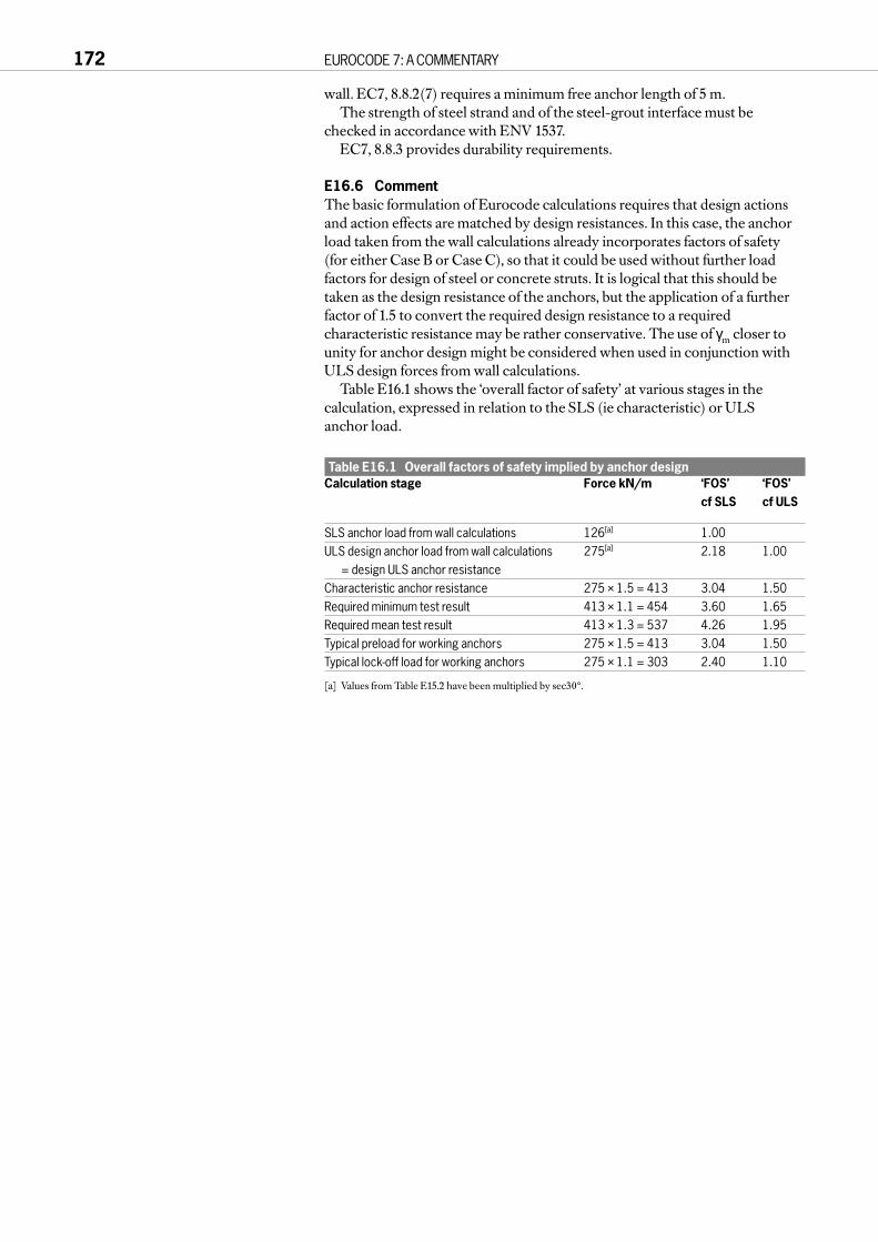
wall. EC7, 8.8.2(7) requires a minimum free anchor length of 5 m.The strength of steel strand and of the steel-grout interface must be
checked in accordance with ENV 1537.EC7, 8.8.3 provides durability requirements.
E16.6 CommentThe basic formulation of Eurocode calculations requires that design actionsand action effects are matched by design resistances. In this case, the anchorload taken from the wall calculations already incorporates factors of safety(for either Case B or Case C), so that it could be used without further loadfactors for design of steel or concrete struts. It is logical that this should betaken as the design resistance of the anchors, but the application of a furtherfactor of 1.5 to convert the required design resistance to a requiredcharacteristic resistance may be rather conservative. The use of γm closer tounity for anchor design might be considered when used in conjunction withULS design forces from wall calculations.
Table E16.1 shows the ‘overall factor of safety’ at various stages in thecalculation, expressed in relation to the SLS (ie characteristic) or ULS anchor load.
Table E16.1 Overall factors of safety implied by anchor designCalculation stage Force kN/m ‘FOS’ ‘FOS’
cf SLS cf ULS
SLS anchor load from wall calculations 126[a] 1.00ULS design anchor load from wall calculations 275[a] 2.18 1.00
= design ULS anchor resistanceCharacteristic anchor resistance 275 × 1.5 = 413 3.04 1.50Required minimum test result 413 × 1.1 = 454 3.60 1.65Required mean test result 413 × 1.3 = 537 4.26 1.95Typical preload for working anchors 275 × 1.5 = 413 3.04 1.50Typical lock-off load for working anchors 275 × 1.1 = 303 2.40 1.10
[a] Values from Table E15.2 have been multiplied by sec30°.
172 EUROCODE 7: A COMMENTARY

E17 DESIGN OF SLOPE IN DRAINED GROUND
E17.1 IntroductionEC7, 9.5 considers the design of slopes and embankments by adopting partialfactors for permanent and variable actions and specific ground properties. Itstates that these factors shall generally be used for verification of ultimate limitstates of conventional types of structures and foundations in persistent andtransient situations.
In C9 it is noted that when considering the Ultimate Limit State for a slopeit is only necessary to consider Case C in Table 2.1. It is noted in Paragraph2.4.2(15) that Case A is only applicable to buoyancy problems and that wherethere is no strength of structural materials involved Case B is irrelevant.
E17.2 DataThe slope in question is a cutting in a stiff overconsolidated clay, as shown inFigure E17.1. The characteristic soil strength properties are:φ′k = 24°c′k = 10 kPa.
The bulk unit weight of the clay is 20kN/m3. The slope is 8 m high and hasan inclination of 22°. Drainage provisions at the site provide a groundwaterlevel which is hydrostatic from 1 m below the finished ground level. There is apermanent UDL of 10 kPa at the top of the slope.
Three slope stability problems have been analysed using the Oasys programSLOPE. The three analyses are:Calculation 1 Demonstration that the slope as designed with the design
parameters satisfies the requirements of EC7;Calculation 2 Calculation of the global Factor of Safety for the slope in
Calculation 1 assuming that the effective cohesion (c′) is equal to zero;
Calculation 3 Calculation of allowable slope using EC7 factors when the effective cohesion is equal to zero.
All analyses use a solution based on Bishop (1955) with variably inclinedinterslice forces.
PART E WORKED EXAMPLES 173
10kPa
φ’k= 24°
c’k= 10kPa
25
20
15
10
5
0
-5
Y (
mO
D)
X (m)10 15 20 25 30 35 40 45 50
Figure E17.1 Slip circle in drained ground

The data and results of the analyses are shown in Table E17.1.The critical slip circle for Calculation 1 is shown in Figure E17.1, and is
typical of the circles for the three calculations.
Table E17.1 Summary of calculationsInput conditions Calculation 1 Calculation 2 Calculation 3
UDLk 10 kPa 10 kPa 10 kPaγUDL 1.3 1.0 1.3UDLd 13 kPa 10 kPa 13 kPaφ′k 24° 24° 24°γ tan φ′ 1.25 1.0 1.25φ′d 19.6° 24.0° 19.6°χ′k 10 kN/m2 0 0γc′ 1.6 – –c′d 6.25 – –Results:
angle of slope 22° 22° 13.9°additional factor of safety, global 1.01 0.84 1.01
E17.3 DiscussionProvided there is sufficient confidence in the characteristic values of theparameters (‘cautious values’ – see B4 and EC7, 2.4.3), only Calculation 1 isneeded to satisfy EC7. It demonstrates that the slope is stable when the partialmaterial factors are applied to the soil strength.
The results of Calculations 1 and 2 show that the effective cohesion, c′ ,plays a very significant role in the stability of the slope. In Calculation 1 theslope is seen to be stable with a global factor of safety in excess of 1.26 (ie 1.25 [γφ] × 1.014 [additional FOS]), satisfying stability requirements.However, in Calculation 2, when the effective cohesion is removed, the slopeis seen to have a global factor of safety of 0.84, which is clearly unacceptable.This leads to the observation that designers must be very confident in theparameters that they use in slope stability analyses. This is particularly thecase where c′ is ascribed to the ground at shallow levels where it plays adominant role in securing the stability of a slope. If it is decided that theeffective cohesion cannot be relied upon, then the slope presented inCalculation 3 will be the limiting design slope. This has an inclination of only13.9° or approximately 1 in 4.
174 EUROCODE 7: A COMMENTARY
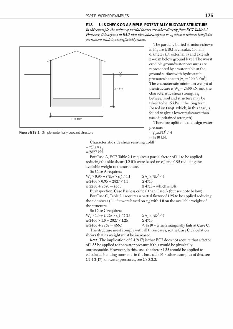
E18 ULS CHECK ON A SIMPLE, POTENTIALLY BUOYANT STRUCTUREIn this example, the values of partial factors are taken directly from EC7 Table 2.1.However, it is argued in B5.7 that the value assigned to γG when it reduces beneficialpermanent loads is uncomfortably small.
The partially buried structure shownin Figure E18.1 is circular, 10 m indiameter (D, externally) and extends z = 6 m below ground level. The worstcredible groundwater pressures arerepresented by a water table at theground surface with hydrostaticpressures beneath (γw = 10 kN/m3).The characteristic minimum weight ofthe structure is Wk = 2400 kN, and thecharacteristic shear strength skbetween soil and structure may betaken to be 15 kPa in the long term(based on tanφ′, which, in this case, isfound to give a lower resistance thanuse of undrained strength).
Therefore uplift due to design waterpressure = γw.z.πD2 / 4 = 4710 kN.
Characteristic side shear resisting uplift = πDz × sk= 2827 kN.
For Case A, EC7 Table 2.1 requires a partial factor of 1.1 to be appliedreducing the side shear (1.2 if it were based on cu) and 0.95 reducing theavailable weight of the structure.
So Case A requires:Wk × 0.95 + (πDz × sk) / 1.1 ≥ γw.z.πD2 / 4ie 2400 × 0.95 + 2827 / 1.1 ≥ 4710ie 2280 + 2570 = 4850 ≥ 4710 – which is OK.
By inspection, Case B is less critical than Case A (but see note below).For Case C, Table 2.1 requires a partial factor of 1.25 to be applied reducing
the side shear (1.4 if it were based on cu) with 1.0 on the available weight of the structure.
So Case C requires:Wk × 1.0 + (πDz × sk) / 1.25 ≥ γw.z.πD2 / 4ie 2400 × 1.0 + 2827 / 1.25 ≥ 4710ie 2400 + 2262 = 4662 < 4710 – which marginally fails at Case C.
The structure must comply with all three cases, so the Case C calculationshows that its weight must be increased.
Note: The implication of 2.4.2(17) is that EC7 does not require that a factorof 1.35 be applied to the water pressure if this would be physicallyunreasonable. However, in this case, the factor 1.35 should be applied tocalculated bending moments in the base slab. For other examples of this, seeC2.4.2(17); on water pressures, see C8.3.2.2.
PART E WORKED EXAMPLES 175
D = 10m
z = 6m
Figure E18.1 Simple, potentially buoyant structure

REFERENCES
AASHTO (1992). Standard specifications for highway bridges. American Association of State Highway and Transportation Officials.
AASHTO (1993). Interim specifications – Bridges. American Association of State Highway and Transportation Officials.
API (1993). Recommended practice for planning, designing and constructing fixed offshore platforms – Working stress design. American Petroleum Institute Recommended Practice2A-WSD (RP 2A-WSD).
ASTM (1985). Axial pile loading test – Part1: Static loading. American Society for Testing Materials Geotechnical Testing Journal 8 (2) 79–90.
Akroyd T N W (1996). Earth-retaining structures: introduction to the Code of Practice, The Structural Engineer 74 (21) 360–4.
Baguelin F, Jezequel J F and Shields D H (1978). The pressuremeter and foundation engineering. Trans Tech Publications Series on Rock and Soil Mechanics, Book 4.
Been K and Jeffries M G (1993). Determination of sand strength for limit state design. Proceedings of International Symposium on Limit State Design in Geotechnical Engineering, Copenhagen. Danish Geotechnical Society.
Bishop A W (1955). The use of the slip circle in the stability analysis of earth slopes. Géotechnique 5 7–17.
Braestrup M W (1996). Application of the Eurocode system to the design of Oresund Link, Proc Int Sem Eurocode 7 – Towards Implementation. London, Institution of Structural Engineers.
Brinch Hansen J (1970). A revised and extended formula for bearing capacity. Geoteknisk InstitutBulletin 28 5–11, Copenhagen.
Brinch Hansen J (1953). Earth pressure calculation. Copenhagen, Danish Technical Press.British Steel (1997). Sections plates and commercial steels, Piling handbook (7th edition).British Steel General Steels, Technical Services Department (1989). Sheet piling in permanent
land based structures. Publication No P106 BS 1377 (1990). Methods of test for soils for civil engineering purposes. London, British
Standards Institution.BS 5930 (1981). Code of practice for site investigations. London, British Standards Institution.BS 5950 (1995). Structural use of steelwork in building. London, British Standards Institution.BS 6031 (1981). Code of practice for earthworks. London, British Standards Institution.BS 6349-3 (1988). Maritime structures. London, British Standards Institution.BS 8002 (1994). Code of practice for earth retaining structures. London, British Standards
Institution.BS 8004 (1986). Code of practice for foundations. London, British Standards Institution.BS 8110 (1985). Structural use of concrete. London, British Standards Institution.BS 8081 (1989). Code of practice for ground anchorages. London, British Standards Institution.Burland J B, Broms B B and de Mello V F B (1978). Behaviour of foundations and structures –
state of the art review. Session II, IX ICSMFE, Tokyo, pp495–545.Butler F G and Morton K (1970). Specification and performance of test piles in clay, ICE
Behaviour of Piles Conference, p17.Carder D R (1998). A comparison of embedded and conventional retaining wall design using
Eurocode 7 and existing UK design methods. TRL Report 320. Crowthorne, Transport Research Laboratory.
Caquot A and Kerisel J (1953). Sur la terme de surface dans le calcul des fondations en Milieu Pulvérult. III ICSMFE, Zurich, 1.
Caquot A, Kerisel J and Absi E (1973). Tables de buté et de poussé. Gauthier-Villars.Chin K E (1972). The inverse slope as a prediction of the ultimate bearing capacity of piles.
Proceedings of the 3rd South East Asian Conference of Soil Engineering, Hong Kong, pp83–91.
Clayton C R I, Milititsky J and Woods R I (1993). Earth pressure and earth-retaining structures. Chapman and Hall.
Cooke R W, Bryden-Smith D W, Gooch M N and Sillett D F (1981). Some observations of the foundation loading and settlement of a multi-storey building on a piled raft foundation in London Clay. Proc Inc Civ Eng, Part 1, August 1981. 70, 433–60.
Department of Transport (1987). Backfilled retaining walls and bridge abutments. Highways & Traffic Departmental Standard BD 30/87. London, DTp.
Det Norske Veritas (DnV) (1992). Foundations. Classification Notes No 30.4.DIN (1996). Eurocode 7 – Entwurf, Berechnung und Bemessung in der Geotechnik. Proc Symp
Deutches Institut für Normung e.V, Mannheim.DIN 1054 (1976). Permissible loading of subsoils. Deutsche Institut für Normung.
177
DIN 4017 (1979). Part 1 Shear failure calculations for shallow foundations with vertical and central loading.
DIN 4017 (1979). Part 2 Shear failure calculations for shallow foundations with oblique and eccentric loading.
EAB (1994). Empfehlungen des Arbeitskreises ‘Baugruben’: 3 – Auflage. Deutschen Gesellschaftfür Geotechnik e.V. Ernst & Sohn.
EAU (1980). Recommendations of the Committee for Waterfront Structures. Wilhelm Ernst & Sohn.EC1 (1994). Eurocode 1: Basis of design and actions on structures (Part 1: Basis of design).
European Committee for Standardisation. ENV 1991-1:1994.EC7 (1995). Eurocode 7: Geotechnical Design – Part 1: General rules, together with the United
Kingdom National Application Document. DD ENV 1997-1:1995. London, British Standards Institution.
Fadum R E (1948). Vertical stress under corner of rectangular area carrying a uniform pressure. ICSMFE No 2 Vol 3, Rotterdam.
Fellenius W (1927). Earth static calculations with friction and cohesion and use of circular sliding surfaces.
Frank R (1994). The new Eurocode and the new French code for the design of deep foundations. Proc Int Conf Design and Construction of Deep Foundations 1. US Federal Highway Administration, pp279–304.
GEO (1993). Guide to retaining wall design. Geoguide 1.Hong Kong, Geotechnical Engineering Office.
Gibson R E (1974). 14th Rankine Lecture: The analytical method in soil mechanics. Géotechnique, 24 (2) 115–40.
Grundbau-Taschenbuch (1992). Vierte Auflage Teil 3 (Ed. U Smoltczyk). Ernst & Sohn.Gudehus G and Weibenbach A (1996). Limit state design of structural parts at and in the ground.
Ground Engineering, 29 (7) 42–5.Health and Safety Commission (1994). The Construction (Design and Management) Regulations.
Statutory Instrument No 3140. London, The Stationery Office.Health and Safety Executive (1996). Safety of New Austrian Tunnelling Method (NATM) Tunnels.Ingold T S (1979). The effects of compaction on retaining walls. Géotechnique 29 (3) 265–84.ICE (1996). Specification for piling and embedded retaining walls. Institution of Civil Engineers.
London, Thomas Telford.ISSMFE (1977). IX ICSMFE, Tokyo. 3, pp156–70.Janbu N (1957). Earth pressures and bearing capacity calculations by generalized procedure of
slices. IV ICSMFE. 2, pp207–12.Kerisel J and Absi E (1990). Active and passive earth pressure tables. Balkema.Mair R J and Wood D M (1987). Pressuremeter testing – Methods and interpretation.
Construction Industry Research and Information Association Ground Engineering Report: in situ testing. London, CIRIA.
Ménard (1975). The Ménard pressuremeter: Interpretation and application of pressuremeter test results to foundation design. Sols-Soils No 26. Techniques Louis Ménard.
Morgernstern N R and Price V E (1965). The analysis of the stability of general slip surfaces. Géotechnique 15 79–93.
Mortensen K (1983). Is limit state design a judgement killer? Sixth Laurits Bjerrum Memorial Lecture, 1982. Publication No 148. Norwegian Geotechnical Institute.
Mortensen K (1993). Statically admissible earth pressure and bearing capacity calculations. Proceedings of the Conference on Retaining Structures organised by the Institution of Civil Engineers, Robinson College, Cambridge, 20–23 July 1992. London, Thomas Telford, 1993.Mortensen K (1995). Kinematically and statically plausible calculations for sheet walls. Canadian
Geo J 32 408–19.Nicholson D P, Tse C-M and Penny C (1997). The Observational Method in ground engineering:
principles and applications. Construction Industry Research and Information Association Funders’ Report CP/49. London, CIRIA.
Orr T L L (1996). Eurocode 7 – Towards implementation. Report of a Seminar at the Institution of Structural Engineers, October 1996. London, ISE.
Orr T L L and O’Brien E J (1996). Examples of the application of Eurocode 1. IABSE Colloquium: Basis of design and actions on structures – background and application of Eurocode 1, Delft.
Padfield C J and Mair R J (1991). Design of retaining walls embedded in stiff clay. Construction Industry Research and Information Association Report 104. London, CIRIA.
Poulos H G and Davis E H (1974). Elastic solutions for soil and rock mechanics. Wiley.prEN 1537 (1997). Ground anchors (CEN pre-standard developed by CEN/TC288).Rowe P W (1952). Anchored sheet-pile walls. Proc ICE 1 (1) 27–70.Rowe P W (1955). A theoretical and experimental analysis of sheet piled walls. Proc ICE 4 32–70.Rowe P W (1957). Sheet pile walls in clay. Proc ICE 7 629–54.Schneider H (1997). Contribution to Discussion Session 2.3. XIV ICSMFE, Hamburg. Balkema.
178 EUROCODE 7: A COMMENTARY

Simpson B, O'Riordan N J and Croft D D (1979). A computer model for the analysis of ground movements in London Clay. Géotechnique 29 (2) 149–75.
Simpson B (1992). Ground–structure interaction. Proc IABSE Conference on Structural Eurocodes, Davos, pp285–90.
Simpson B (1994). Eurocode 7. Seminar on BS 8002 – Code of Practice on Earth Retaining Structures. London, Institution of Structural Engineers.
Simpson B (1996). Basis of design in Eurocode 7. IABSE Colloquium – Basis of design and actions on structures, Delft.
Simpson B (1997). Contribution to Discussion Session 2.3, XIV ICSMFE, Hamburg. Balkema.Site Investigation Steering Group (1993). Without site investigation ground is a hazard. Site
investigation in construction – 1. London, Thomas Telford.Spencer E E (1967). A method of the analysis of the stability of embankments assuming parallel
inter-slice forces. Géotechnique 17 11–26.Terzaghi K. (1954). Anchored bulkheads. Trans-Am Soc Civ Engrs 119 (Paper 2720) 1243–81.Terzaghi K and Peck R B (1967). Soil mechanics in engineering practice. John Wiley and Sons.Tomlinson M J (1994). Pile design and construction practice. Chapman and Hall.Twine D and Roscoe G H (1997). Prop loads: Guidance on design. Construction Industry
Research and Information Association Report FR/CP/48 (Funders Report for CIRIA members due to be published in 1998). London, CIRIA.
Vanmarcke E H (1977). Probabilistic modelling of soil profiles. ASCE Journal of the Geotechnical Engineering Division, November 1977, pp1227–46.
REFERENCES 179