brakes brc a - boredmder - youtubeboredmder.com/fsms/nissan/altima/2007 hybrid/brc.pdfbrc-1 brakes c...
TRANSCRIPT
BRAKES
C
D
E
SECTION BRCA
B
BRAKE CONTROL SYSTEM
G
H
I
J
K
L
M
RC
N
O
P
CONTENTS
BVDC/TCS/ABS
BASIC INSPECTION .................................... 5
DIAGNOSIS AND REPAIR WORKFLOW .......... 5Work Flow .................................................................5
INSPECTION AND ADJUSTMENT ..................... 7
PERFORM INITIALIZATION OF LINEAR SOLE-NOID VALVE AND CALIBRATION .............................7
PERFORM INITIALIZATION OF LINEAR SOLE-NOID VALVE AND CALIBRATION : Description ......7PERFORM INITIALIZATION OF LINEAR SOLE-NOID VALVE AND CALIBRATION : Special Re-pair Requirement .......................................................7
PERFORM ZERO POINT OF YAW RATE/SIDE/DECEL G SENSOR .....................................................8
PERFORM ZERO POINT OF YAW RATE/SIDE/DECEL G SENSOR : Description .............................8PERFORM ZERO POINT OF YAW RATE/SIDE/DECEL G SENSOR : Special Repair Requirement
......8
PERFORM ADJUSTMENT OF STROKE SENSOR ......9PERFORM ADJUSTMENT OF STROKE SEN-SOR : Description .....................................................9PERFORM ADJUSTMENT OF STROKE SEN-SOR : Special Repair Requirement ..........................9
PERFORM ZERO POINT OF STEERING ANGLE SENSOR ......................................................................9
PERFORM ZERO POINT OF STEERING ANGLE SENSOR : Description ..............................................9PERFORM ZERO POINT OF STEERING ANGLE SENSOR : Special Repair Requirement ...................9
BASIC INSPECTION ..........................................11TEST MODE PROCEDURE ...................................11
FUNCTION DIAGNOSIS ..............................14
ELECTRONICALLY CONTROLLED BRAKE SYSTEM ............................................................14
System Diagram ......................................................14System Description ..................................................14Component Parts Location ......................................15Component Description ...........................................17
ABS ...................................................................20System Diagram ......................................................20System Description ..................................................20Component Parts Location ......................................21Component Description ...........................................23
EBD ...................................................................26System Diagram ......................................................26System Description ..................................................26Component Parts Location ......................................27Component Description ...........................................29
TCS ....................................................................32System Diagram ......................................................32System Description ..................................................32Component Parts Location ......................................33Component Description ...........................................35
VDC ...................................................................38System Diagram ......................................................38System Description ..................................................38Component Parts Location ......................................39Component Description ...........................................41
INSPECTION MODE .........................................44System Description ..................................................44
DIAGNOSIS SYSTEM (VDC/TCS/ABS CON-TROL UNIT) ......................................................45
CONSULT-III Function ............................................45
COMPONENT DIAGNOSIS .........................57
C0200, C0205, C1271, C1272 ..........................57Description ...............................................................57
BRC-1
DTC Logic ............................................................... 57Diagnosis Procedure .............................................. 58Special Repair Requirement ................................... 61
C0210, C0215, C1273, C1274 ........................... 62Description .............................................................. 62DTC Logic ............................................................... 62Diagnosis Procedure .............................................. 62Special Repair Requirement ................................... 66
C0371, C1234, C1232, C1243, C1244, C1245, C1279, C1381 .................................................... 67
Description .............................................................. 67DTC Logic ............................................................... 67Diagnosis Procedure .............................................. 67Special Repair Requirement ................................... 68
C1155 ................................................................. 70Description .............................................................. 70DTC Logic ............................................................... 70Diagnosis Procedure .............................................. 70Special Repair Requirement ................................... 71
C11A0, C1336 .................................................... 72Description .............................................................. 72DTC Logic ............................................................... 72Diagnosis Procedure .............................................. 72Special Repair Requirement ................................... 73
C1231 ................................................................. 74Description .............................................................. 74DTC Logic ............................................................... 74Diagnosis Procedure .............................................. 74Special Repair Requirement ................................... 75
C1235, C1236, C1238, C1239, C1275, C1276, C1277, C1278 .................................................... 76
Description .............................................................. 76DTC Logic ............................................................... 76Diagnosis Procedure .............................................. 76Special Repair Requirement ................................... 80
C1241, C1242 .................................................... 81Description .............................................................. 81DTC Logic ............................................................... 81Diagnosis Procedure .............................................. 82Special Repair Requirement ................................... 83
C1246, C1281, C1364 ........................................ 84Description .............................................................. 84DTC Logic ............................................................... 84Diagnosis Procedure .............................................. 86Special Repair Requirement ................................... 88
C1247, C1346, C1392 ........................................ 89Description .............................................................. 89DTC Logic ............................................................... 89Diagnosis Procedure .............................................. 89Special Repair Requirement ................................... 92
C1249 ................................................................. 93
Description .............................................................. 93DTC Logic ............................................................... 93Diagnosis Procedure ............................................... 93Special Repair Requirement ................................... 95
C1252, C1253 .................................................... 96Description .............................................................. 96DTC Logic ............................................................... 96Diagnosis Procedure ............................................... 96Special Repair Requirement ................................. 100
C1256 ................................................................101Description ............................................................ 101DTC Logic ............................................................. 101Diagnosis Procedure ............................................. 101Special Repair Requirement ................................. 102
C1259, C1310 ...................................................104Description ............................................................ 104DTC Logic ............................................................. 104Diagnosis Procedure ............................................. 104Special Repair Requirement ................................. 104
C1290 ................................................................105Description ............................................................ 105DTC Logic ............................................................. 105Diagnosis Procedure ............................................. 105Special Repair Requirement ................................. 106
C1300 ................................................................107Description ............................................................ 107DTC Logic ............................................................. 107Diagnosis Procedure ............................................. 107Special Repair Requirement ................................. 107
C1311, C1312, C1313, C1314 ..........................108Description ............................................................ 108DTC Logic ............................................................. 108Diagnosis Procedure ............................................. 108Special Repair Requirement ................................. 110
C1315, C1316, C1352, C1353, C1354, C1355, C1356, C1357, C1358, C1359 ..........................111
Description ............................................................ 111DTC Logic ............................................................. 111Diagnosis Procedure ............................................. 112Special Repair Requirement ................................. 115
C1319 ................................................................116Description ............................................................ 116DTC Logic ............................................................. 116Diagnosis Procedure ............................................. 116Special Repair Requirement ................................. 117
C1341, C1342, C1343, C1344 ..........................118Description ............................................................ 118DTC Logic ............................................................. 118Diagnosis Procedure ............................................. 118Special Repair Requirement ................................. 120
C1345, C1368 ...................................................122
BRC-2
C
D
E
G
H
I
J
K
L
M
A
B
RC
N
O
P
B
Description ............................................................ 122DTC Logic ............................................................. 122Diagnosis Procedure ............................................. 122Special Repair Requirement ................................. 123
C1365 ............................................................... 124Description ............................................................ 124DTC Logic ............................................................. 124Diagnosis Procedure ............................................. 124Special Repair Requirement ................................. 125
C1377 ............................................................... 126Description ............................................................ 126DTC Logic ............................................................. 126Diagnosis Procedure ............................................. 126Special Repair Requirement ................................. 128
C1378 ............................................................... 130Description ............................................................ 130DTC Logic ............................................................. 130Diagnosis Procedure ............................................. 130Special Repair Requirement ................................. 131
C1391 ............................................................... 132Description ............................................................ 132DTC Logic ............................................................. 132Diagnosis Procedure ............................................. 132Special Repair Requirement ................................. 133
U0073, U0123, U0124, U0126, U0293 ............. 134Description ............................................................ 134DTC Logic ............................................................. 134Diagnosis Procedure ............................................. 135
ECU DIAGNOSIS ....................................... 137
ABS ACTUATOR AND ELECTRIC UNIT (CONTROL UNIT) ............................................ 137
Reference Value ................................................... 137Wiring Diagram - BRAKE CONTROL SYSTEM - .. 142DTC Index ............................................................. 156
SYMPTOM DIAGNOSIS ............................ 163
VDC/TCS/ABS SYMPTOMS ............................ 163Symptom Table ..................................................... 163
ABS WARNING LAMP REMAINS ON ............. 165Description ............................................................ 165Diagnosis Procedure ............................................. 165
ABS WARNING LAMP DOES NOT COME ON ..167
Description ............................................................ 167Diagnosis Procedure ............................................. 167
VDC WARNING LAMP REMAINS ON ............. 168Description ............................................................ 168Diagnosis Procedure ............................................. 168
VDC WARNING LAMP DOES NOT COME ON ..169
Description .............................................................169Diagnosis Procedure .............................................169
BRAKE WARNING LAMP REMAINS ON ...... 170Description .............................................................170Diagnosis Procedure .............................................170
BRAKE WARNING LAMP DOES NOT COME ON ................................................................... 173
Description .............................................................173Diagnosis Procedure .............................................173
ELECTRONICALLY CONTROLLED BRAKE WARNING LAMP REMAINS ON .................... 174
Description .............................................................174Diagnosis Procedure .............................................174
ELECTRONICALLY CONTROLLED BRAKE WARNING LAMP DOES NOT COME ON ...... 175
Description .............................................................175Diagnosis Procedure .............................................175
SLIP INDICATOR LAMP REMAINS ON ......... 177Description .............................................................177Diagnosis Procedure .............................................177
SLIP INDICATOR LAMP DOES NOT COME ON ................................................................... 178
Description .............................................................178Diagnosis Procedure .............................................178
BRAKE WARNING BUZZER CIRCUIT .......... 179Description .............................................................179Diagnosis Procedure .............................................179
PRECAUTION ............................................ 181
PRECAUTIONS ............................................... 181Precaution for Supplemental Restraint System (SRS) "AIR BAG" and "SEAT BELT PRE-TEN-SIONER" ...............................................................181Precautions For High-Voltage System ..................181Precautions for Inspecting the Hybrid Control Sys-tem .........................................................................181Electronically Controlled Brake System .................182
PREPARATION ......................................... 184
PREPARATION ............................................... 184Special Service Tool ..............................................184Commercial Service Tool ......................................184
ON-VEHICLE MAINTENANCE .................. 185
BRAKE ECU ................................................... 185Inspection ..............................................................185
BRAKE ACTUATOR ....................................... 186Inspection ..............................................................186
WHEEL SENSOR ............................................ 187Inspection ..............................................................187
BRC-3

ABS RELAY NO. 1 AND NO. 2 ....................... 188Inspection ..............................................................188
ABS MOTOR RELAY NO. 1 AND NO. 2 ......... 189Inspection ..............................................................189
ON-VEHICLE REPAIR ...............................190
BRAKE ECU .................................................... 190Exploded View .......................................................190Removal and Installation .......................................190
BRAKE ACTUATOR ....................................... 192Exploded View .......................................................192Removal and Installation .......................................192Disposal .................................................................193
WHEEL SENSOR ............................................ 195Exploded View .......................................................195Removal and Installation .......................................195
SENSOR ROTOR ............................................ 197Removal and Installation .......................................197
YAW RATE/SIDE/DECEL G SENSOR ............198Removal and Installation ....................................... 198
STEERING ANGLE SENSOR ..........................199Removal and Installation ....................................... 199
BRAKE WARNING BUZZER ...........................200Removal and Installation ....................................... 200
CAPACITOR .....................................................201Exploded View ...................................................... 201Removal and Installation ....................................... 201
BRAKE STROKE SENSOR .............................202Exploded View ...................................................... 202Removal and Installation ....................................... 202
BRAKE SIMULATOR .......................................204Exploded View ...................................................... 204Removal and Installation ....................................... 205Disassembly and Assembly .................................. 206
BRC-4
DIAGNOSIS AND REPAIR WORKFLOW[VDC/TCS/ABS]
C
D
E
G
H
I
J
K
L
M
A
B
RC
N
O
P
< BASIC INSPECTION >
B
BASIC INSPECTIONDIAGNOSIS AND REPAIR WORKFLOW
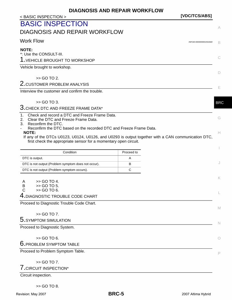
Work Flow INFOID:0000000001501840
NOTE:*: Use the CONSULT-III.
1.VEHICLE BROUGHT TO WORKSHOP
Vehicle brought to workshop.
>> GO TO 2.
2.CUSTOMER PROBLEM ANALYSIS
Interview the customer and confirm the trouble.
>> GO TO 3.
3.CHECK DTC AND FREEZE FRAME DATA*
1. Check and record a DTC and Freeze Frame Data.2. Clear the DTC and Freeze Frame Data.3. Reconfirm the DTC.- Reconfirm the DTC based on the recorded DTC and Freeze Frame Data.
NOTE:If any of the DTCs U0123, U0124, U0126, and U0293 is output together with a CAN communication DTC,
first check the appropriate sensor for a momentary open circuit.
A >> GO TO 4.B >> GO TO 5.C >> GO TO 6.
4.DIAGNOSTIC TROUBLE CODE CHART
Proceed to Diagnostic Trouble Code Chart.
>> GO TO 7.
5.SYMPTOM SIMULATION
Proceed to Diagnostic System.
>> GO TO 6.
6.PROBLEM SYMPTOM TABLE
Proceed to Problem Symptom Table.
>> GO TO 7.
7.CIRCUIT INSPECTION*
Circuit inspection.
>> GO TO 8.
Condition Proceed to
DTC is output. A
DTC is not output (Problem symptom does not occur). B
DTC is not output (Problem symptom occurs). C
BRC-5
[VDC/TCS/ABS]DIAGNOSIS AND REPAIR WORKFLOW
< BASIC INSPECTION >
8.IDENTIFICATION OF PROBLEM
Identification of problem.
>> GO TO 9.
9.REPAIR OR REPALCEMENT
Repair or replacement.
>> GO TO 10.
10.CONFIRMATION TEST*
Confirmation test.
>> END
BRC-6

INSPECTION AND ADJUSTMENT[VDC/TCS/ABS]
C
D
E
G
H
I
J
K
L
M
A
B
RC
N
O
P
< BASIC INSPECTION >
B
INSPECTION AND ADJUSTMENTPERFORM INITIALIZATION OF LINEAR SOLENOID VALVE AND CALIBRATION
PERFORM INITIALIZATION OF LINEAR SOLENOID VALVE AND CALIBRATION : Description INFOID:0000000001501841
Perform initialization of linear solenoid valve and calibration when the brake ECU, brake actuator or brakestroke sensor is replaced. Follow the procedure to perform initialization.NOTE:• If there is a problem with the auxiliary battery (12 V) voltage, initialization of linear solenoid valve and calibra-
tion cannot be completed normally. Make sure to check the auxiliary battery voltage before performing initial-ization of linear solenoid valve and calibration.
• If the actuator′s temperature is high, initialization of linear solenoid valve and calibration may not be com-pleted normally. In such a case, wait until the temperature decreases and then perform initialization of linearsolenoid valve and calibration.
• If the ignition switch is turned OFF, the brake pedal is operated or vehicle speed is input while the linear sole-noid valve offset learning is being performed, the learning will be cancelled.
PERFORM INITIALIZATION OF LINEAR SOLENOID VALVE AND CALIBRATION : Special Repair Requirement INFOID:0000000001501842
1. Clear the stored value of linear solenoid valve and calibration data.a. Turn the ignition switch OFF.b. Connect the CONSULT-III.c. Move the shift lever to the P position.d. Turn the ignition switch ON with the brake pedal released.e. Clear the stored value of initialization of linear solenoid valve and calibration. Refer to BRC-45, "CON-
SULT-III Function".f. Using the CONSULT-III, perform initialization of linear solenoid valve and calibration.2. Perform the initialization of linear solenoid valve and calibration.a. Turn the ignition switch OFF.b. Connect the CONSULT-III.c. Move the shift lever to the P position.d. Turn the ignition switch ON (READY) with the brake pedal depressed.
NOTE:• If the linear solenoid valve offset learning is performed without turning the ignition switch ON, the learn-
ing process may not be completed properly because of insufficient auxiliary battery voltage.• When the linear solenoid valve offset learning is interrupted, or the learning process is performed with
the shift lever not in the P position, DTC C1345 will be stored.e. Select “TEST MODE” in “WORK SOPPORT” to start TEST MODE.f. Leave the vehicle stationary without depressing the brake pedal for 1 or 2 minutes.g. Check that the interval between blinks of the Electronically Controlled Brake warning lamp changes from
1 second to 0.5 seconds.NOTE:
Replacement parts Necessary operation
Brake ECU1. Initialization of linear solenoid valve and calibration2. Steering angle sensor zero point calibration
Brake actuator assembly1. Bleed air2. Clearing stored value of linear solenoid valve and calibration data3. Initialization of linear solenoid valve and calibration
• Brake stroke sensor• Brake pedal
1. Inspection and adjustment of brake pedal height2. Clearing stored value of linear solenoid valve and calibration data3. Initialization of linear solenoid valve and calibration
BRC-7
[VDC/TCS/ABS]INSPECTION AND ADJUSTMENT
< BASIC INSPECTION >• While the linear solenoid valve is learning, the Electronically Controlled Brake warning lamp blinks at
intervals of 1 second. It blinks at intervals of 0.5 seconds after the completion of the learning.• The time needed to complete initialization of linear solenoid valve and calibration varies depending on
auxiliary battery voltage.• The Electronically Controlled Brake warning lamp blinks at 1 second intervals during initialization of lin-
ear solenoid valve.• The Electronically Controlled Brake warning lamp blinks 0.25 seconds intervals if the CONSULT-III
prompts.h. Select “TEST MODE END”.
PERFORM ZERO POINT OF YAW RATE/SIDE/DECEL G SENSOR
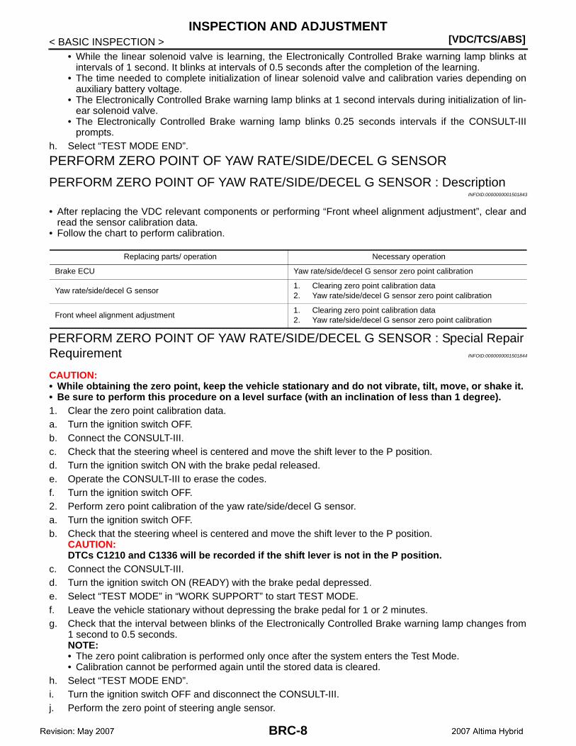
PERFORM ZERO POINT OF YAW RATE/SIDE/DECEL G SENSOR : DescriptionINFOID:0000000001501843
• After replacing the VDC relevant components or performing “Front wheel alignment adjustment”, clear andread the sensor calibration data.
• Follow the chart to perform calibration.
PERFORM ZERO POINT OF YAW RATE/SIDE/DECEL G SENSOR : Special Repair Requirement INFOID:0000000001501844
CAUTION:• While obtaining the zero point, keep the vehicle stationary and do not vibrate, tilt, move, or shake it.• Be sure to perform this procedure on a level surface (with an inclination of less than 1 degree).1. Clear the zero point calibration data.a. Turn the ignition switch OFF.b. Connect the CONSULT-III.c. Check that the steering wheel is centered and move the shift lever to the P position.d. Turn the ignition switch ON with the brake pedal released.e. Operate the CONSULT-III to erase the codes.f. Turn the ignition switch OFF.2. Perform zero point calibration of the yaw rate/side/decel G sensor.a. Turn the ignition switch OFF.b. Check that the steering wheel is centered and move the shift lever to the P position.
CAUTION:DTCs C1210 and C1336 will be recorded if the shift lever is not in the P position.
c. Connect the CONSULT-III.d. Turn the ignition switch ON (READY) with the brake pedal depressed.e. Select “TEST MODE” in “WORK SUPPORT” to start TEST MODE.f. Leave the vehicle stationary without depressing the brake pedal for 1 or 2 minutes.g. Check that the interval between blinks of the Electronically Controlled Brake warning lamp changes from
1 second to 0.5 seconds.NOTE:• The zero point calibration is performed only once after the system enters the Test Mode.• Calibration cannot be performed again until the stored data is cleared.
h. Select “TEST MODE END”.i. Turn the ignition switch OFF and disconnect the CONSULT-III.j. Perform the zero point of steering angle sensor.
Replacing parts/ operation Necessary operation
Brake ECU Yaw rate/side/decel G sensor zero point calibration
Yaw rate/side/decel G sensor1. Clearing zero point calibration data2. Yaw rate/side/decel G sensor zero point calibration
Front wheel alignment adjustment1. Clearing zero point calibration data2. Yaw rate/side/decel G sensor zero point calibration
BRC-8

INSPECTION AND ADJUSTMENT[VDC/TCS/ABS]
C
D
E
G
H
I
J
K
L
M
A
B
RC
N
O
P
< BASIC INSPECTION >
B
PERFORM ADJUSTMENT OF STROKE SENSOR
PERFORM ADJUSTMENT OF STROKE SENSOR : Description INFOID:0000000001501845
After removing or adjusting brake stroke sensor, adjustments are necessary.
PERFORM ADJUSTMENT OF STROKE SENSOR : Special Repair RequirementINFOID:0000000001501846
1. Clear the stored value of stroke sensor data.a. Connect the connector to the brake stroke sensor.b. Connect the CONSULT-III with the ignition switch OFF.c. Turn the ignition switch ON.d. Reading the “STROKE SEN” value shown in the DATA MONITOR, slowly turn the brake stroke sensor to
the right and left to adjust the value to the standard voltage.
e. Fully tighten the mounting bolts.CAUTION:Do not depress the brake pedal after turning the ignition switch ON.
f. Move the shift lever to the P position.g. Turn the ignition switch ON with the brake pedal released.h. Clear the stored value of stroke sensor.i. Using the CONSULT-III, perform adjustment of stroke sensor.2. Perform the adjustment of stroke sensor.a. Turn the ignition switch OFF.b. Connect the CONSULT-III.c. Move the shift lever to the P position.d. Turn the ignition switch ON (READY) with the brake pedal depressed.
NOTE:• If the stroke sensor offset learning is performed without turning the ignition switch ON, the learning pro-
cess may not be completed properly because of insufficient auxiliary battery voltage.• When the stroke sensor offset learning is interrupted, or the learning process is performed with the shift
lever not in the P position.e. Select “TEST MODE” in “WORK SUPPORT” to start TEST MODE.f. Leave the vehicle stationary without depressing the brake pedal for 1 to 2 minutes.g. Check that the interval between blinks of the Electronically Controlled Brake warning lamp.
NOTE:• The time needed to complete adjustment of stroke sensor varies depending on auxiliary battery voltage.• The Electronically Controlled Brake warning lamp blinks at 1 second interval during adjustment of stroke
sensor.h. Select “TEST MODE END”.
PERFORM ZERO POINT OF STEERING ANGLE SENSOR
PERFORM ZERO POINT OF STEERING ANGLE SENSOR : Description INFOID:0000000001501847
When brake ECU or steering angle sensor is replaced, or battery is removed, perform zero adjustment forsteering angle sensor.
PERFORM ZERO POINT OF STEERING ANGLE SENSOR : Special Repair Require-ment INFOID:0000000001501848
1. After the procedure, perform straight-ahead driving for 5 seconds or more at 35 km/h (22 MPH) or more.2. After driving, check that VDC warning lamp is OFF.NOTE:
Standard voltage : 0.8 to 1.2 V
BRC-9

[VDC/TCS/ABS]INSPECTION AND ADJUSTMENT
< BASIC INSPECTION >If VDC warning lamp does not turn OFF, perform self-diagnosis for brake ECU.
BRC-10
BASIC INSPECTION[VDC/TCS/ABS]
C
D
E
G
H
I
J
K
L
M
A
B
RC
N
O
P
< BASIC INSPECTION >
B
BASIC INSPECTION
TEST MODE PROCEDURE INFOID:0000000001501849
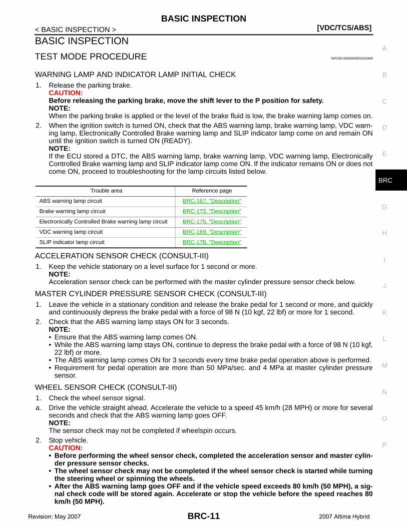
WARNING LAMP AND INDICATOR LAMP INITIAL CHECK1. Release the parking brake.
CAUTION:Before releasing the parking brake, move the shift lever to the P position for safety.NOTE:When the parking brake is applied or the level of the brake fluid is low, the brake warning lamp comes on.
2. When the ignition switch is turned ON, check that the ABS warning lamp, brake warning lamp, VDC warn-ing lamp, Electronically Controlled Brake warning lamp and SLIP indicator lamp come on and remain ONuntil the ignition switch is turned ON (READY).NOTE:If the ECU stored a DTC, the ABS warning lamp, brake warning lamp, VDC warning lamp, ElectronicallyControlled Brake warning lamp and SLIP indicator lamp come ON. If the indicator remains ON or does notcome ON, proceed to troubleshooting for the lamp circuits listed below.
ACCELERATION SENSOR CHECK (CONSULT-III)1. Keep the vehicle stationary on a level surface for 1 second or more.
NOTE:Acceleration sensor check can be performed with the master cylinder pressure sensor check below.
MASTER CYLINDER PRESSURE SENSOR CHECK (CONSULT-III)1. Leave the vehicle in a stationary condition and release the brake pedal for 1 second or more, and quickly
and continuously depress the brake pedal with a force of 98 N (10 kgf, 22 lbf) or more for 1 second.2. Check that the ABS warning lamp stays ON for 3 seconds.
NOTE:• Ensure that the ABS warning lamp comes ON.• While the ABS warning lamp stays ON, continue to depress the brake pedal with a force of 98 N (10 kgf,
22 lbf) or more.• The ABS warning lamp comes ON for 3 seconds every time brake pedal operation above is performed.• Requirement for pedal operation are more than 50 MPa/sec. and 4 MPa at master cylinder pressure
sensor.
WHEEL SENSOR CHECK (CONSULT-III)1. Check the wheel sensor signal.a. Drive the vehicle straight ahead. Accelerate the vehicle to a speed 45 km/h (28 MPH) or more for several
seconds and check that the ABS warning lamp goes OFF.NOTE:The sensor check may not be completed if wheelspin occurs.
2. Stop vehicle.CAUTION:• Before performing the wheel sensor check, completed the acceleration sensor and master cylin-
der pressure sensor checks.• The wheel sensor check may not be completed if the wheel sensor check is started while turning
the steering wheel or spinning the wheels.• After the ABS warning lamp goes OFF and if the vehicle speed exceeds 80 km/h (50 MPH), a sig-
nal check code will be stored again. Accelerate or stop the vehicle before the speed reaches 80km/h (50 MPH).
Trouble area Reference page
ABS warning lamp circuit BRC-167, "Description"
Brake warning lamp circuit BRC-173, "Description"
Electronically Controlled Brake warning lamp circuit BRC-175, "Description"
VDC warning lamp circuit BRC-169, "Description"
SLIP indicator lamp circuit BRC-178, "Description"
BRC-11
[VDC/TCS/ABS]BASIC INSPECTION
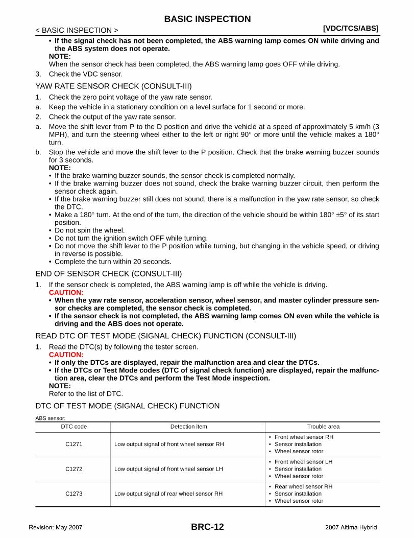
< BASIC INSPECTION >• If the signal check has not been completed, the ABS warning lamp comes ON while driving and
the ABS system does not operate.NOTE:When the sensor check has been completed, the ABS warning lamp goes OFF while driving.
3. Check the VDC sensor.
YAW RATE SENSOR CHECK (CONSULT-III)1. Check the zero point voltage of the yaw rate sensor.a. Keep the vehicle in a stationary condition on a level surface for 1 second or more.2. Check the output of the yaw rate sensor.a. Move the shift lever from P to the D position and drive the vehicle at a speed of approximately 5 km/h (3
MPH), and turn the steering wheel either to the left or right 90° or more until the vehicle makes a 180°turn.
b. Stop the vehicle and move the shift lever to the P position. Check that the brake warning buzzer soundsfor 3 seconds.NOTE:• If the brake warning buzzer sounds, the sensor check is completed normally.• If the brake warning buzzer does not sound, check the brake warning buzzer circuit, then perform the
sensor check again.• If the brake warning buzzer still does not sound, there is a malfunction in the yaw rate sensor, so check
the DTC.• Make a 180° turn. At the end of the turn, the direction of the vehicle should be within 180° ±5° of its start
position.• Do not spin the wheel.• Do not turn the ignition switch OFF while turning.• Do not move the shift lever to the P position while turning, but changing in the vehicle speed, or driving
in reverse is possible.• Complete the turn within 20 seconds.
END OF SENSOR CHECK (CONSULT-III)1. If the sensor check is completed, the ABS warning lamp is off while the vehicle is driving.
CAUTION:• When the yaw rate sensor, acceleration sensor, wheel sensor, and master cylinder pressure sen-
sor checks are completed, the sensor check is completed.• If the sensor check is not completed, the ABS warning lamp comes ON even while the vehicle is
driving and the ABS does not operate.
READ DTC OF TEST MODE (SIGNAL CHECK) FUNCTION (CONSULT-III)1. Read the DTC(s) by following the tester screen.
CAUTION:• If only the DTCs are displayed, repair the malfunction area and clear the DTCs.• If the DTCs or Test Mode codes (DTC of signal check function) are displayed, repair the malfunc-
tion area, clear the DTCs and perform the Test Mode inspection.NOTE:Refer to the list of DTC.
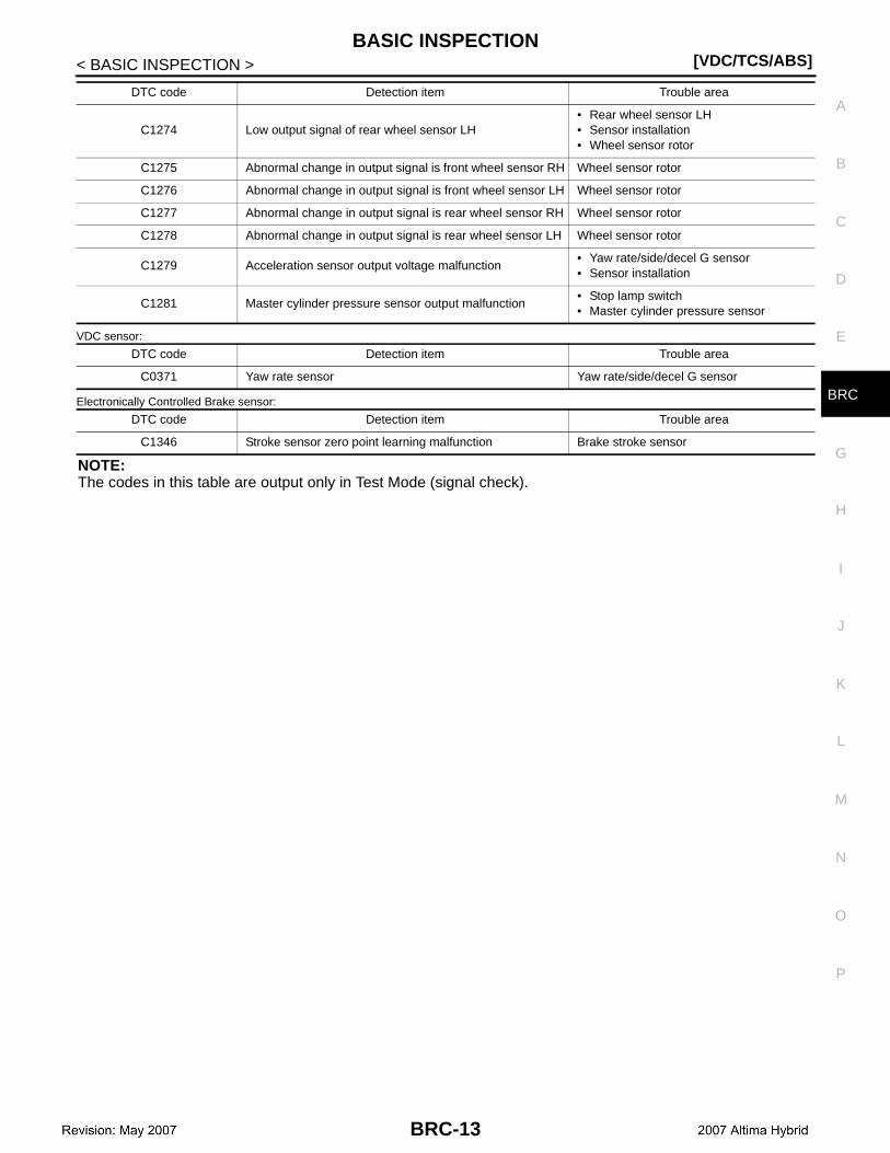
DTC OF TEST MODE (SIGNAL CHECK) FUNCTION
ABS sensor:
DTC code Detection item Trouble area
C1271 Low output signal of front wheel sensor RH• Front wheel sensor RH• Sensor installation• Wheel sensor rotor
C1272 Low output signal of front wheel sensor LH• Front wheel sensor LH• Sensor installation• Wheel sensor rotor
C1273 Low output signal of rear wheel sensor RH• Rear wheel sensor RH• Sensor installation• Wheel sensor rotor
BRC-12
BASIC INSPECTION[VDC/TCS/ABS]
C
D
E
G
H
I
J
K
L
M
A
B
RC
N
O
P
< BASIC INSPECTION >
B
VDC sensor:
Electronically Controlled Brake sensor:
NOTE:The codes in this table are output only in Test Mode (signal check).
C1274 Low output signal of rear wheel sensor LH• Rear wheel sensor LH• Sensor installation• Wheel sensor rotor
C1275 Abnormal change in output signal is front wheel sensor RH Wheel sensor rotor
C1276 Abnormal change in output signal is front wheel sensor LH Wheel sensor rotor
C1277 Abnormal change in output signal is rear wheel sensor RH Wheel sensor rotor
C1278 Abnormal change in output signal is rear wheel sensor LH Wheel sensor rotor
C1279 Acceleration sensor output voltage malfunction• Yaw rate/side/decel G sensor• Sensor installation
C1281 Master cylinder pressure sensor output malfunction• Stop lamp switch• Master cylinder pressure sensor
DTC code Detection item Trouble area
C0371 Yaw rate sensor Yaw rate/side/decel G sensor
DTC code Detection item Trouble area
C1346 Stroke sensor zero point learning malfunction Brake stroke sensor
DTC code Detection item Trouble area
BRC-13
[VDC/TCS/ABS]ELECTRONICALLY CONTROLLED BRAKE SYSTEM
< FUNCTION DIAGNOSIS >
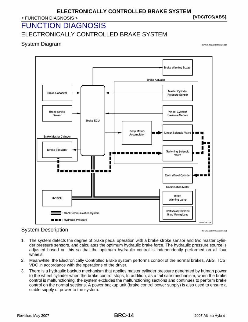
FUNCTION DIAGNOSISELECTRONICALLY CONTROLLED BRAKE SYSTEM
System Diagram INFOID:0000000001501850
System Description INFOID:0000000001501851
1. The system detects the degree of brake pedal operation with a brake stroke sensor and two master cylin-der pressure sensors, and calculates the optimum hydraulic brake force. The hydraulic pressure source isadjusted based on this so that the optimum hydraulic control is independently performed on all fourwheels.
2. Meanwhile, the Electronically Controlled Brake system performs control of the normal brakes, ABS, TCS,VDC in accordance with the operations of the driver.
3. There is a hydraulic backup mechanism that applies master cylinder pressure generated by human powerto the wheel cylinder when the brake control stops, In addition, as a fail safe mechanism, when the brakecontrol is malfunctioning, the system excludes the malfunctioning sections and continues to perform brakecontrol on the normal sections. A power backup unit (brake control power supply) is also used to ensure astable supply of power to the system.
JSFIA0062GB
BRC-14

ELECTRONICALLY CONTROLLED BRAKE SYSTEM[VDC/TCS/ABS]
C
D
E
G
H
I
J
K
L
M
A
B
RC
N
O
P
< FUNCTION DIAGNOSIS >
B
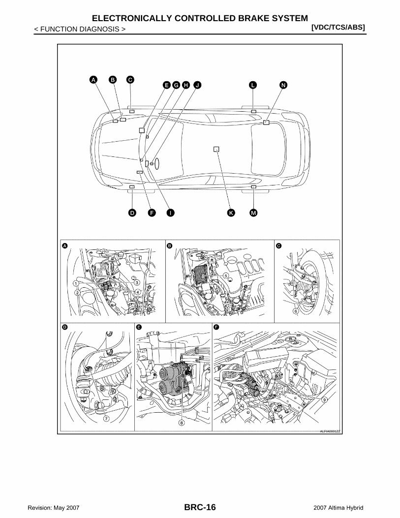
Component Parts Location INFOID:0000000001501852
BRC-15
[VDC/TCS/ABS]ELECTRONICALLY CONTROLLED BRAKE SYSTEM
< FUNCTION DIAGNOSIS >
ALFIA0001ZZ
BRC-16

ELECTRONICALLY CONTROLLED BRAKE SYSTEM[VDC/TCS/ABS]
C
D
E
G
H
I
J
K
L
M
A
B
RC
N
O
P
< FUNCTION DIAGNOSIS >
B
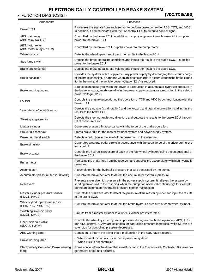
Component Description INFOID:0000000001501853
1. ABS relay No.1 2. ABS motor relay No.1 3. ABS motor relay No.2
4. ABS relay No.2 5. Brake ECU 6. Front RH wheel sensor
7. Front LH wheel sensor 8. Brake actuator 9. Brake simulator
10. Brake warning buzzer 11. Brake stroke sensor 12. VDC warning lamp
13. SLIP indicator lamp 14. ABS warning lamp 15. Brake warning lamp (For US)
16. Brake warning lamp (For CANADA) 17. Electronically Controlled Brake warning lamp
18. Steering angle sensor
19. Yaw rate/side/decel G sensor 20. Rear RH wheel sensor 21. Rear LH wheel sensor
22. Brake capacitor
A. Engine room right side B. Engine room right side C. Steering knuckle (RH)
D. Steering knuckle (LH) E. Engine room right side F. Engine room left side
G. Cluster lid C H. Instrument driver panel lower I. Combination meter
J. Spiral cable assembly K. Center Console L. Rear knuckle (RH)
M. Rear knuckle N. Trunk room right side
ALFIA0002ZZ
BRC-17
[VDC/TCS/ABS]ELECTRONICALLY CONTROLLED BRAKE SYSTEM
< FUNCTION DIAGNOSIS >
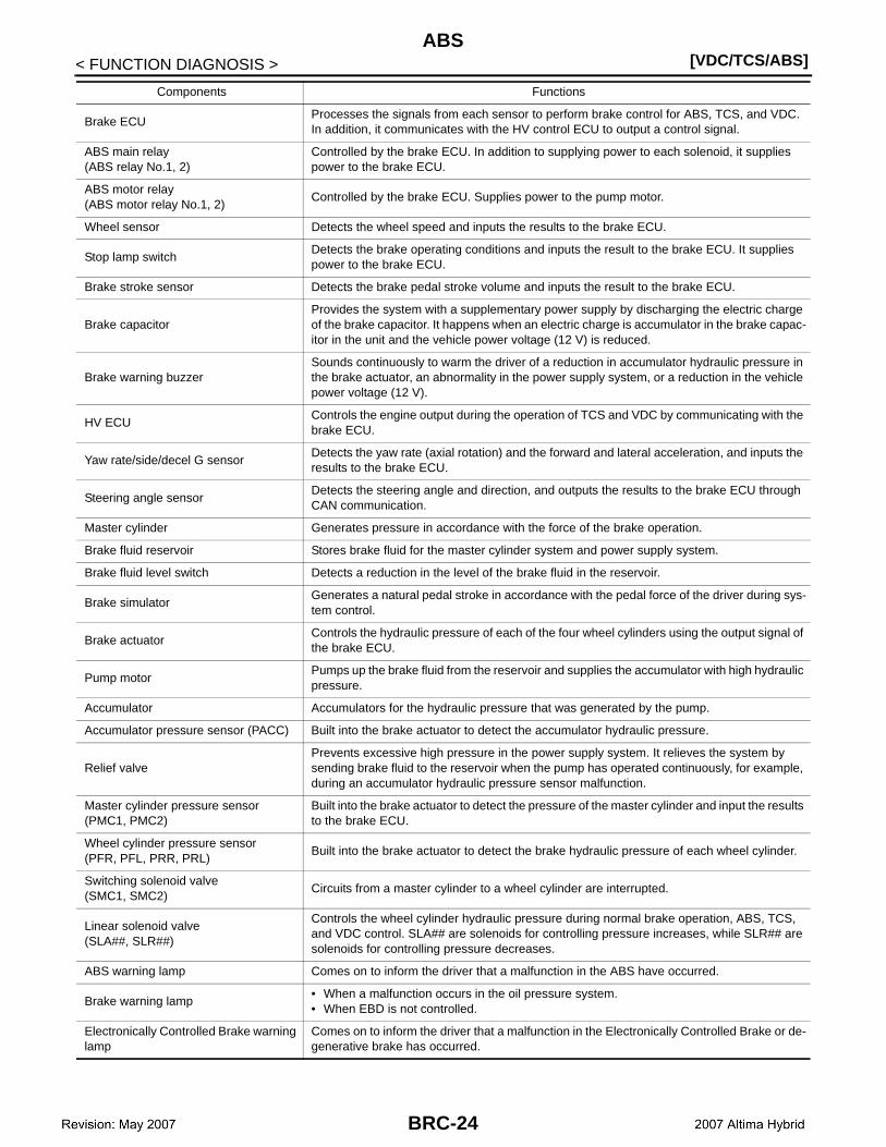
Components Functions
Brake ECUProcesses the signals from each sensor to perform brake control for ABS, TCS, and VDC. In addition, it communicates with the HV control ECU to output a control signal.
ABS main relay(ABS relay No.1, 2)
Controlled by the brake ECU. In addition to supplying power to each solenoid, it supplies power to the brake ECU.
ABS motor relay(ABS motor relay No.1, 2)
Controlled by the brake ECU. Supplies power to the pump motor.
Wheel sensor Detects the wheel speed and inputs the results to the brake ECU.
Stop lamp switchDetects the brake operating conditions and inputs the result to the brake ECU. It supplies power to the brake ECU.
Brake stroke sensor Detects the brake pedal stroke volume and inputs the result to the brake ECU.
Brake capacitorProvides the system with a supplementary power supply by discharging the electric charge of the brake capacitor. It happens when an electric charge is accumulator in the brake capac-itor in the unit and the vehicle power voltage (12 V) is reduced.
Brake warning buzzerSounds continuously to warm the driver of a reduction in accumulator hydraulic pressure in the brake actuator, an abnormality in the power supply system, or a reduction in the vehicle power voltage (12 V).
HV ECUControls the engine output during the operation of TCS and VDC by communicating with the brake ECU.
Yaw rate/side/decel G sensorDetects the yaw rate (axial rotation) and the forward and lateral acceleration, and inputs the results to the brake ECU.
Steering angle sensorDetects the steering angle and direction, and outputs the results to the brake ECU through CAN communication.
Master cylinder Generates pressure in accordance with the force of the brake operation.
Brake fluid reservoir Stores brake fluid for the master cylinder system and power supply system.
Brake fluid level switch Detects a reduction in the level of the brake fluid in the reservoir.
Brake simulatorGenerates a natural pedal stroke in accordance with the pedal force of the driver during sys-tem control.
Brake actuatorControls the hydraulic pressure of each of the four wheel cylinders using the output signal of the brake ECU.
Pump motorPumps up the brake fluid from the reservoir and supplies the accumulator with high hydraulic pressure.
Accumulator Accumulators for the hydraulic pressure that was generated by the pump.
Accumulator pressure sensor (PACC) Built into the brake actuator to detect the accumulator hydraulic pressure.
Relief valvePrevents excessive high pressure in the power supply system. It relieves the system by sending brake fluid to the reservoir when the pump has operated continuously, for example, during an accumulator hydraulic pressure sensor malfunction.
Master cylinder pressure sensor(PMC1, PMC2)
Built into the brake actuator to detect the pressure of the master cylinder and input the results to the brake ECU.
Wheel cylinder pressure sensor(PFR, PFL, PRR, PRL)
Built into the brake actuator to detect the brake hydraulic pressure of each wheel cylinder.
Switching solenoid valve(SMC1, SMC2)
Circuits from a master cylinder to a wheel cylinder are interrupted.
Linear solenoid valve(SLA##, SLR##)
Controls the wheel cylinder hydraulic pressure during normal brake operation, ABS, TCS, and VDC control. SLA## are solenoids for controlling pressure increases, while SLR## are solenoids for controlling pressure decreases.
ABS warning lamp Comes on to inform the driver that a malfunction in the ABS have occurred.
Brake warning lamp• When a malfunction occurs in the oil pressure system.• When EBD is not controlled.
Electronically Controlled Brake warning lamp
Comes on to inform the driver that a malfunction in the Electronically Controlled Brake or de-generative brake has occurred.
BRC-18

ELECTRONICALLY CONTROLLED BRAKE SYSTEM[VDC/TCS/ABS]
C
D
E
G
H
I
J
K
L
M
A
B
RC
N
O
P
< FUNCTION DIAGNOSIS >
B
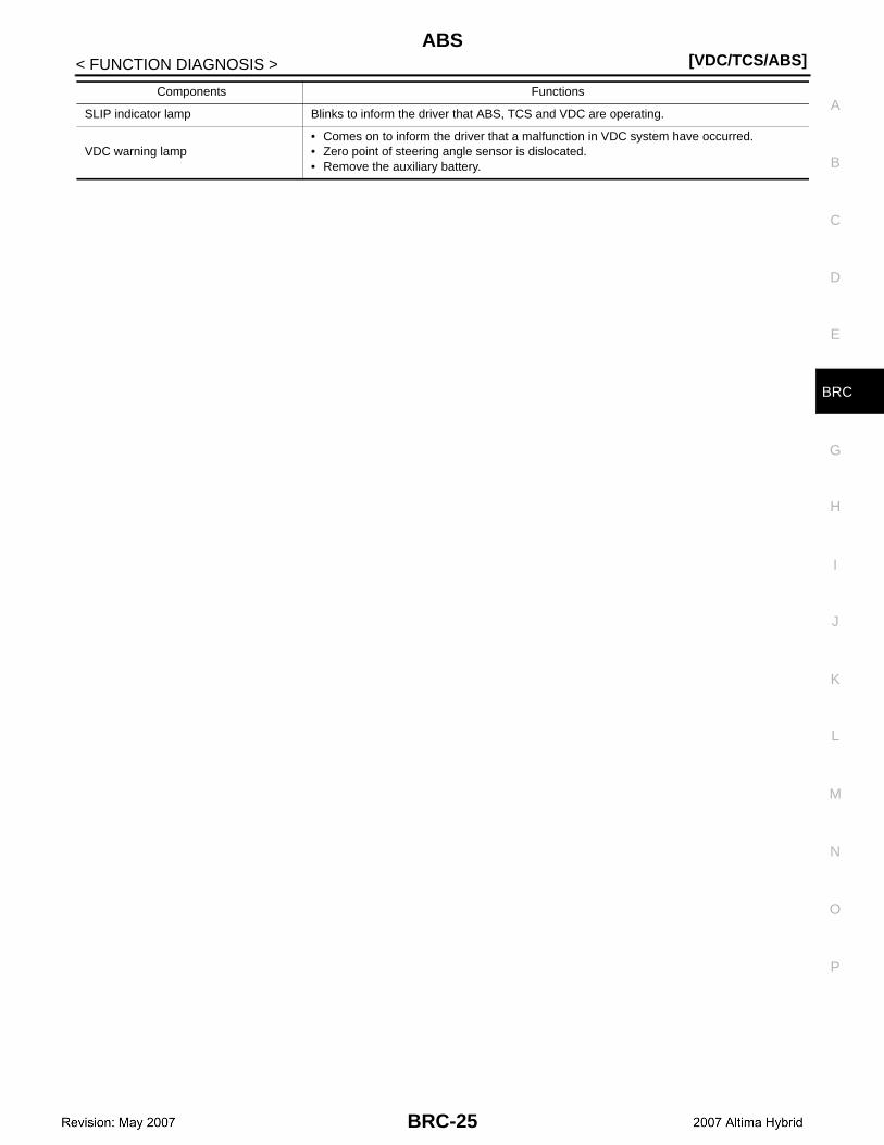
SLIP indicator lamp Blinks to inform the driver that ABS, TCS and VDC are operating.
VDC warning lamp• Comes on to inform the driver that a malfunction in VDC system have occurred.• Zero point of steering angle sensor is dislocated.• Remove the auxiliary battery.
Components Functions
BRC-19

[VDC/TCS/ABS]ABS
< FUNCTION DIAGNOSIS >
ABS
System Diagram INFOID:0000000001501854
System Description INFOID:0000000001501855
SYSTEM DESCRIPTIONThe ABS (Anti-lock Braking System) helps prevent the wheels from locking when the brakes are applied sud-denly and firmly or applied on a slippery surface.
OPERATION DESCRIPTIONThe brake ECU detects wheel lock based on speed signals it receives from the wheel sensors. Based on thisinformation, and yaw rate/side/decel G sensor signals, the brake ECU controls the solenoid valves are used toprevent wheel lock by controlling the hydraulic pressure applied to the brakes at each wheel. The SLIP indica-tor lamp blinks when the system is operating. The ABS warning lamp will come ON when the system is mal-functioning.
JSFIA0057GB
BRC-20
ABS[VDC/TCS/ABS]
C
D
E
G
H
I
J
K
L
M
A
B
RC
N
O
P
< FUNCTION DIAGNOSIS >
B
Component Parts Location INFOID:0000000001501856
BRC-21

[VDC/TCS/ABS]ABS
< FUNCTION DIAGNOSIS >
ALFIA0001ZZ
BRC-22

ABS[VDC/TCS/ABS]
C
D
E
G
H
I
J
K
L
M
A
B
RC
N
O
P
< FUNCTION DIAGNOSIS >
B
Component Description INFOID:0000000001501857
1. ABS relay No.1 2. ABS motor relay No.1 3. ABS motor relay No.2
4. ABS relay No.2 5. Brake ECU 6. Front RH wheel sensor
7. Front LH wheel sensor 8. Brake actuator 9. Brake simulator
10. Brake warning buzzer 11. Brake stroke sensor 12. VDC warning lamp
13. SLIP indicator lamp 14. ABS warning lamp 15. Brake warning lamp (For US)
16. Brake warning lamp (For CANADA) 17. Electronically Controlled Brake warning lamp
18. Steering angle sensor
19. Yaw rate/side/decel G sensor 20. Rear RH wheel sensor 21. Rear LH wheel sensor
22. Brake capacitor
A. Engine room right side B. Engine room right side C. Steering knuckle (RH)
D. Steering knuckle (LH) E. Engine room right side F. Engine room left side
G. Cluster lid C H. Instrument driver panel lower I. Combination meter
J. Spiral cable assembly K. Center Console L. Rear knuckle (RH)
M. Rear knuckle N. Trunk room right side
ALFIA0002ZZ
BRC-23
[VDC/TCS/ABS]ABS
< FUNCTION DIAGNOSIS >
Components Functions
Brake ECUProcesses the signals from each sensor to perform brake control for ABS, TCS, and VDC. In addition, it communicates with the HV control ECU to output a control signal.
ABS main relay(ABS relay No.1, 2)
Controlled by the brake ECU. In addition to supplying power to each solenoid, it supplies power to the brake ECU.
ABS motor relay(ABS motor relay No.1, 2)
Controlled by the brake ECU. Supplies power to the pump motor.
Wheel sensor Detects the wheel speed and inputs the results to the brake ECU.
Stop lamp switchDetects the brake operating conditions and inputs the result to the brake ECU. It supplies power to the brake ECU.
Brake stroke sensor Detects the brake pedal stroke volume and inputs the result to the brake ECU.
Brake capacitorProvides the system with a supplementary power supply by discharging the electric charge of the brake capacitor. It happens when an electric charge is accumulator in the brake capac-itor in the unit and the vehicle power voltage (12 V) is reduced.
Brake warning buzzerSounds continuously to warm the driver of a reduction in accumulator hydraulic pressure in the brake actuator, an abnormality in the power supply system, or a reduction in the vehicle power voltage (12 V).
HV ECUControls the engine output during the operation of TCS and VDC by communicating with the brake ECU.
Yaw rate/side/decel G sensorDetects the yaw rate (axial rotation) and the forward and lateral acceleration, and inputs the results to the brake ECU.
Steering angle sensorDetects the steering angle and direction, and outputs the results to the brake ECU through CAN communication.
Master cylinder Generates pressure in accordance with the force of the brake operation.
Brake fluid reservoir Stores brake fluid for the master cylinder system and power supply system.
Brake fluid level switch Detects a reduction in the level of the brake fluid in the reservoir.
Brake simulatorGenerates a natural pedal stroke in accordance with the pedal force of the driver during sys-tem control.
Brake actuatorControls the hydraulic pressure of each of the four wheel cylinders using the output signal of the brake ECU.
Pump motorPumps up the brake fluid from the reservoir and supplies the accumulator with high hydraulic pressure.
Accumulator Accumulators for the hydraulic pressure that was generated by the pump.
Accumulator pressure sensor (PACC) Built into the brake actuator to detect the accumulator hydraulic pressure.
Relief valvePrevents excessive high pressure in the power supply system. It relieves the system by sending brake fluid to the reservoir when the pump has operated continuously, for example, during an accumulator hydraulic pressure sensor malfunction.
Master cylinder pressure sensor(PMC1, PMC2)
Built into the brake actuator to detect the pressure of the master cylinder and input the results to the brake ECU.
Wheel cylinder pressure sensor(PFR, PFL, PRR, PRL)
Built into the brake actuator to detect the brake hydraulic pressure of each wheel cylinder.
Switching solenoid valve(SMC1, SMC2)
Circuits from a master cylinder to a wheel cylinder are interrupted.
Linear solenoid valve(SLA##, SLR##)
Controls the wheel cylinder hydraulic pressure during normal brake operation, ABS, TCS, and VDC control. SLA## are solenoids for controlling pressure increases, while SLR## are solenoids for controlling pressure decreases.
ABS warning lamp Comes on to inform the driver that a malfunction in the ABS have occurred.
Brake warning lamp• When a malfunction occurs in the oil pressure system.• When EBD is not controlled.
Electronically Controlled Brake warning lamp
Comes on to inform the driver that a malfunction in the Electronically Controlled Brake or de-generative brake has occurred.
BRC-24
ABS[VDC/TCS/ABS]
C
D
E
G
H
I
J
K
L
M
A
B
RC
N
O
P
< FUNCTION DIAGNOSIS >
B
SLIP indicator lamp Blinks to inform the driver that ABS, TCS and VDC are operating.
VDC warning lamp• Comes on to inform the driver that a malfunction in VDC system have occurred.• Zero point of steering angle sensor is dislocated.• Remove the auxiliary battery.
Components Functions
BRC-25
[VDC/TCS/ABS]EBD
< FUNCTION DIAGNOSIS >
EBD
System Diagram INFOID:0000000001501858
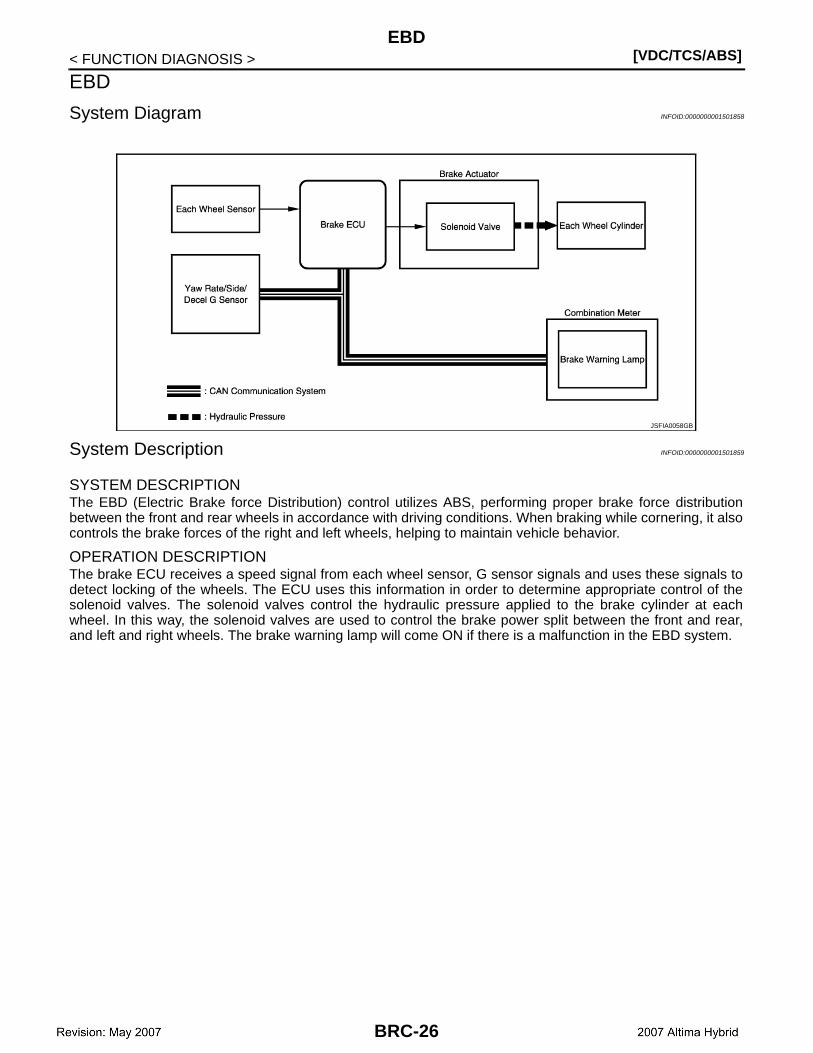
System Description INFOID:0000000001501859
SYSTEM DESCRIPTIONThe EBD (Electric Brake force Distribution) control utilizes ABS, performing proper brake force distributionbetween the front and rear wheels in accordance with driving conditions. When braking while cornering, it alsocontrols the brake forces of the right and left wheels, helping to maintain vehicle behavior.
OPERATION DESCRIPTIONThe brake ECU receives a speed signal from each wheel sensor, G sensor signals and uses these signals todetect locking of the wheels. The ECU uses this information in order to determine appropriate control of thesolenoid valves. The solenoid valves control the hydraulic pressure applied to the brake cylinder at eachwheel. In this way, the solenoid valves are used to control the brake power split between the front and rear,and left and right wheels. The brake warning lamp will come ON if there is a malfunction in the EBD system.
JSFIA0058GB
BRC-26
EBD[VDC/TCS/ABS]
C
D
E
G
H
I
J
K
L
M
A
B
RC
N
O
P
< FUNCTION DIAGNOSIS >
B
Component Parts Location INFOID:0000000001501860
BRC-27

[VDC/TCS/ABS]EBD
< FUNCTION DIAGNOSIS >
ALFIA0001ZZ
BRC-28

EBD[VDC/TCS/ABS]
C
D
E
G
H
I
J
K
L
M
A
B
RC
N
O
P
< FUNCTION DIAGNOSIS >
B
Component Description INFOID:0000000001501861
1. ABS relay No.1 2. ABS motor relay No.1 3. ABS motor relay No.2
4. ABS relay No.2 5. Brake ECU 6. Front RH wheel sensor
7. Front LH wheel sensor 8. Brake actuator 9. Brake simulator
10. Brake warning buzzer 11. Brake stroke sensor 12. VDC warning lamp
13. SLIP indicator lamp 14. ABS warning lamp 15. Brake warning lamp (For US)
16. Brake warning lamp (For CANADA) 17. Electronically Controlled Brake warning lamp
18. Steering angle sensor
19. Yaw rate/side/decel G sensor 20. Rear RH wheel sensor 21. Rear LH wheel sensor
22. Brake capacitor
A. Engine room right side B. Engine room right side C. Steering knuckle (RH)
D. Steering knuckle (LH) E. Engine room right side F. Engine room left side
G. Cluster lid C H. Instrument driver panel lower I. Combination meter
J. Spiral cable assembly K. Center Console L. Rear knuckle (RH)
M. Rear knuckle N. Trunk room right side
ALFIA0002ZZ
BRC-29

[VDC/TCS/ABS]EBD
< FUNCTION DIAGNOSIS >
Components Functions
Brake ECUProcesses the signals from each sensor to perform brake control for ABS, TCS, and VDC. In addition, it communicates with the HV control ECU to output a control signal.
ABS main relay(ABS relay No.1, 2)
Controlled by the brake ECU. In addition to supplying power to each solenoid, it supplies power to the brake ECU.
ABS motor relay(ABS motor relay No.1, 2)
Controlled by the brake ECU. Supplies power to the pump motor.
Wheel sensor Detects the wheel speed and inputs the results to the brake ECU.
Stop lamp switchDetects the brake operating conditions and inputs the result to the brake ECU. It supplies power to the brake ECU.
Brake stroke sensor Detects the brake pedal stroke volume and inputs the result to the brake ECU.
Brake capacitorProvides the system with a supplementary power supply by discharging the electric charge of the brake capacitor. It happens when an electric charge is accumulator in the brake capac-itor in the unit and the vehicle power voltage (12 V) is reduced.
Brake warning buzzerSounds continuously to warm the driver of a reduction in accumulator hydraulic pressure in the brake actuator, an abnormality in the power supply system, or a reduction in the vehicle power voltage (12 V).
HV ECUControls the engine output during the operation of TCS and VDC by communicating with the brake ECU.
Yaw rate/side/decel G sensorDetects the yaw rate (axial rotation) and the forward and lateral acceleration, and inputs the results to the brake ECU.
Steering angle sensorDetects the steering angle and direction, and outputs the results to the brake ECU through CAN communication.
Master cylinder Generates pressure in accordance with the force of the brake operation.
Brake fluid reservoir Stores brake fluid for the master cylinder system and power supply system.
Brake fluid level switch Detects a reduction in the level of the brake fluid in the reservoir.
Brake simulatorGenerates a natural pedal stroke in accordance with the pedal force of the driver during sys-tem control.
Brake actuatorControls the hydraulic pressure of each of the four wheel cylinders using the output signal of the brake ECU.
Pump motorPumps up the brake fluid from the reservoir and supplies the accumulator with high hydraulic pressure.
Accumulator Accumulators for the hydraulic pressure that was generated by the pump.
Accumulator pressure sensor (PACC) Built into the brake actuator to detect the accumulator hydraulic pressure.
Relief valvePrevents excessive high pressure in the power supply system. It relieves the system by sending brake fluid to the reservoir when the pump has operated continuously, for example, during an accumulator hydraulic pressure sensor malfunction.
Master cylinder pressure sensor(PMC1, PMC2)
Built into the brake actuator to detect the pressure of the master cylinder and input the results to the brake ECU.
Wheel cylinder pressure sensor(PFR, PFL, PRR, PRL)
Built into the brake actuator to detect the brake hydraulic pressure of each wheel cylinder.
Switching solenoid valve(SMC1, SMC2)
Circuits from a master cylinder to a wheel cylinder are interrupted.
Linear solenoid valve(SLA##, SLR##)
Controls the wheel cylinder hydraulic pressure during normal brake operation, ABS, TCS, and VDC control. SLA## are solenoids for controlling pressure increases, while SLR## are solenoids for controlling pressure decreases.
ABS warning lamp Comes on to inform the driver that a malfunction in the ABS have occurred.
Brake warning lamp• When a malfunction occurs in the oil pressure system.• When EBD is not controlled.
Electronically Controlled Brake warning lamp
Comes on to inform the driver that a malfunction in the Electronically Controlled Brake or de-generative brake has occurred.
BRC-30

EBD[VDC/TCS/ABS]
C
D
E
G
H
I
J
K
L
M
A
B
RC
N
O
P
< FUNCTION DIAGNOSIS >
B
SLIP indicator lamp Blinks to inform the driver that ABS, TCS and VDC are operating.
VDC warning lamp• Comes on to inform the driver that a malfunction in VDC system have occurred.• Zero point of steering angle sensor is dislocated.• Remove the auxiliary battery.
Components Functions
BRC-31
[VDC/TCS/ABS]TCS
< FUNCTION DIAGNOSIS >
TCS
System Diagram INFOID:0000000001501862
System Description INFOID:0000000001501863
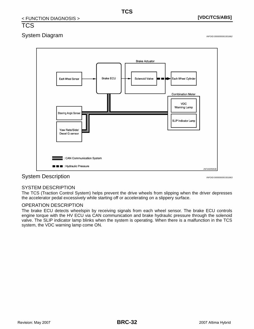
SYSTEM DESCRIPTIONThe TCS (Traction Control System) helps prevent the drive wheels from slipping when the driver depressesthe accelerator pedal excessively while starting off or accelerating on a slippery surface.
OPERATION DESCRIPTIONThe brake ECU detects wheelspin by receiving signals from each wheel sensor. The brake ECU controlsengine torque with the HV ECU via CAN communication and brake hydraulic pressure through the solenoidvalve. The SLIP indicator lamp blinks when the system is operating. When there is a malfunction in the TCSsystem, the VDC warning lamp come ON.
JSFIA0059GB
BRC-32

TCS[VDC/TCS/ABS]
C
D
E
G
H
I
J
K
L
M
A
B
RC
N
O
P
< FUNCTION DIAGNOSIS >
B
Component Parts Location INFOID:0000000001501864
BRC-33
[VDC/TCS/ABS]TCS
< FUNCTION DIAGNOSIS >
ALFIA0001ZZ
BRC-34

TCS[VDC/TCS/ABS]
C
D
E
G
H
I
J
K
L
M
A
B
RC
N
O
P
< FUNCTION DIAGNOSIS >
B
Component Description INFOID:0000000001501865
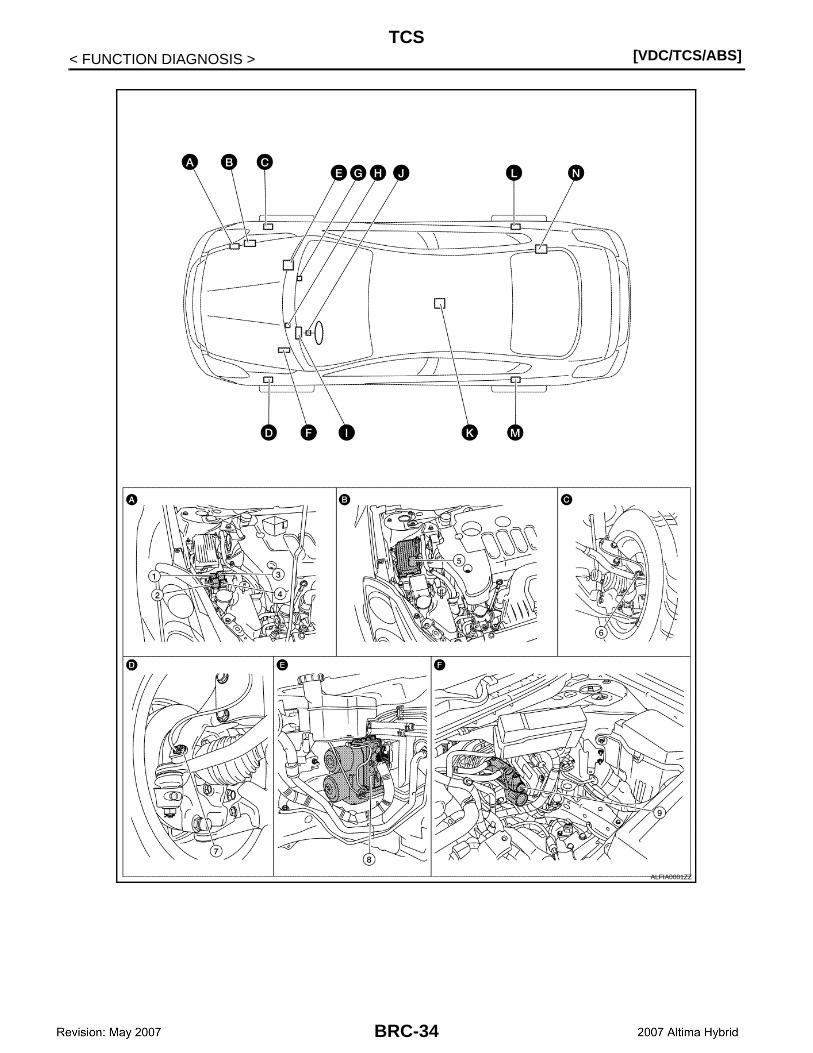
1. ABS relay No.1 2. ABS motor relay No.1 3. ABS motor relay No.2
4. ABS relay No.2 5. Brake ECU 6. Front RH wheel sensor
7. Front LH wheel sensor 8. Brake actuator 9. Brake simulator
10. Brake warning buzzer 11. Brake stroke sensor 12. VDC warning lamp
13. SLIP indicator lamp 14. ABS warning lamp 15. Brake warning lamp (For US)
16. Brake warning lamp (For CANADA) 17. Electronically Controlled Brake warning lamp
18. Steering angle sensor
19. Yaw rate/side/decel G sensor 20. Rear RH wheel sensor 21. Rear LH wheel sensor
22. Brake capacitor
A. Engine room right side B. Engine room right side C. Steering knuckle (RH)
D. Steering knuckle (LH) E. Engine room right side F. Engine room left side
G. Cluster lid C H. Instrument driver panel lower I. Combination meter
J. Spiral cable assembly K. Center Console L. Rear knuckle (RH)
M. Rear knuckle N. Trunk room right side
ALFIA0002ZZ
BRC-35

[VDC/TCS/ABS]TCS
< FUNCTION DIAGNOSIS >
Components Functions
Brake ECUProcesses the signals from each sensor to perform brake control for ABS, TCS, and VDC. In addition, it communicates with the HV control ECU to output a control signal.
ABS main relay(ABS relay No.1, 2)
Controlled by the brake ECU. In addition to supplying power to each solenoid, it supplies power to the brake ECU.
ABS motor relay(ABS motor relay No.1, 2)
Controlled by the brake ECU. Supplies power to the pump motor.
Wheel sensor Detects the wheel speed and inputs the results to the brake ECU.
Stop lamp switchDetects the brake operating conditions and inputs the result to the brake ECU. It supplies power to the brake ECU.
Brake stroke sensor Detects the brake pedal stroke volume and inputs the result to the brake ECU.
Brake capacitorProvides the system with a supplementary power supply by discharging the electric charge of the brake capacitor. It happens when an electric charge is accumulator in the brake capac-itor in the unit and the vehicle power voltage (12 V) is reduced.
Brake warning buzzerSounds continuously to warm the driver of a reduction in accumulator hydraulic pressure in the brake actuator, an abnormality in the power supply system, or a reduction in the vehicle power voltage (12 V).
HV ECUControls the engine output during the operation of TCS and VDC by communicating with the brake ECU.
Yaw rate/side/decel G sensorDetects the yaw rate (axial rotation) and the forward and lateral acceleration, and inputs the results to the brake ECU.
Steering angle sensorDetects the steering angle and direction, and outputs the results to the brake ECU through CAN communication.
Master cylinder Generates pressure in accordance with the force of the brake operation.
Brake fluid reservoir Stores brake fluid for the master cylinder system and power supply system.
Brake fluid level switch Detects a reduction in the level of the brake fluid in the reservoir.
Brake simulatorGenerates a natural pedal stroke in accordance with the pedal force of the driver during sys-tem control.
Brake actuatorControls the hydraulic pressure of each of the four wheel cylinders using the output signal of the brake ECU.
Pump motorPumps up the brake fluid from the reservoir and supplies the accumulator with high hydraulic pressure.
Accumulator Accumulators for the hydraulic pressure that was generated by the pump.
Accumulator pressure sensor (PACC) Built into the brake actuator to detect the accumulator hydraulic pressure.
Relief valvePrevents excessive high pressure in the power supply system. It relieves the system by sending brake fluid to the reservoir when the pump has operated continuously, for example, during an accumulator hydraulic pressure sensor malfunction.
Master cylinder pressure sensor(PMC1, PMC2)
Built into the brake actuator to detect the pressure of the master cylinder and input the results to the brake ECU.
Wheel cylinder pressure sensor(PFR, PFL, PRR, PRL)
Built into the brake actuator to detect the brake hydraulic pressure of each wheel cylinder.
Switching solenoid valve(SMC1, SMC2)
Circuits from a master cylinder to a wheel cylinder are interrupted.
Linear solenoid valve(SLA##, SLR##)
Controls the wheel cylinder hydraulic pressure during normal brake operation, ABS, TCS, and VDC control. SLA## are solenoids for controlling pressure increases, while SLR## are solenoids for controlling pressure decreases.
ABS warning lamp Comes on to inform the driver that a malfunction in the ABS have occurred.
Brake warning lamp• When a malfunction occurs in the oil pressure system.• When EBD is not controlled.
Electronically Controlled Brake warning lamp
Comes on to inform the driver that a malfunction in the Electronically Controlled Brake or de-generative brake has occurred.
BRC-36

TCS[VDC/TCS/ABS]
C
D
E
G
H
I
J
K
L
M
A
B
RC
N
O
P
< FUNCTION DIAGNOSIS >
B
SLIP indicator lamp Blinks to inform the driver that ABS, TCS and VDC are operating.
VDC warning lamp• Comes on to inform the driver that a malfunction in VDC system have occurred.• Zero point of steering angle sensor is dislocated.• Remove the auxiliary battery.
Components Functions
BRC-37
[VDC/TCS/ABS]VDC
< FUNCTION DIAGNOSIS >
VDC
System Diagram INFOID:0000000001501866
System Description INFOID:0000000001501867
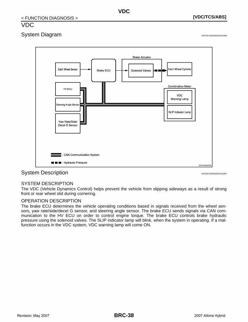
SYSTEM DESCRIPTIONThe VDC (Vehicle Dynamics Control) helps prevent the vehicle from slipping sideways as a result of strongfront or rear wheel slid during cornering.
OPERATION DESCRIPTIONThe brake ECU determines the vehicle operating conditions based in signals received from the wheel sen-sors, yaw rate/side/decel G sensor, and steering angle sensor. The brake ECU sends signals via CAN com-munication to the HV ECU on order to control engine torque. The brake ECU controls brake hydraulicpressure using the solenoid valves. The SLIP indicator lamp will blink, when the system in operating. If a mal-function occurs in the VDC system, VDC warning lamp will come ON.
JSFIA0060GB
BRC-38

VDC[VDC/TCS/ABS]
C
D
E
G
H
I
J
K
L
M
A
B
RC
N
O
P
< FUNCTION DIAGNOSIS >
B
Component Parts Location INFOID:0000000001501868
BRC-39

[VDC/TCS/ABS]VDC
< FUNCTION DIAGNOSIS >
ALFIA0001ZZ
BRC-40
VDC[VDC/TCS/ABS]
C
D
E
G
H
I
J
K
L
M
A
B
RC
N
O
P
< FUNCTION DIAGNOSIS >
B
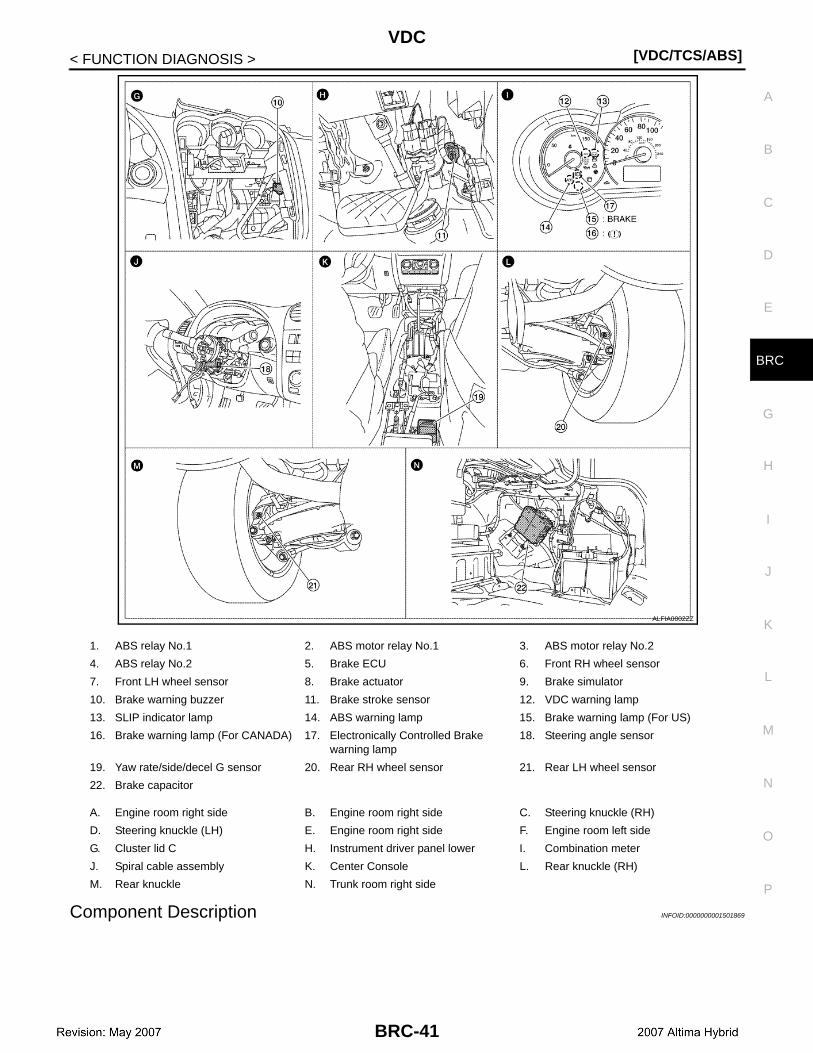
Component Description INFOID:0000000001501869
1. ABS relay No.1 2. ABS motor relay No.1 3. ABS motor relay No.2
4. ABS relay No.2 5. Brake ECU 6. Front RH wheel sensor
7. Front LH wheel sensor 8. Brake actuator 9. Brake simulator
10. Brake warning buzzer 11. Brake stroke sensor 12. VDC warning lamp
13. SLIP indicator lamp 14. ABS warning lamp 15. Brake warning lamp (For US)
16. Brake warning lamp (For CANADA) 17. Electronically Controlled Brake warning lamp
18. Steering angle sensor
19. Yaw rate/side/decel G sensor 20. Rear RH wheel sensor 21. Rear LH wheel sensor
22. Brake capacitor
A. Engine room right side B. Engine room right side C. Steering knuckle (RH)
D. Steering knuckle (LH) E. Engine room right side F. Engine room left side
G. Cluster lid C H. Instrument driver panel lower I. Combination meter
J. Spiral cable assembly K. Center Console L. Rear knuckle (RH)
M. Rear knuckle N. Trunk room right side
ALFIA0002ZZ
BRC-41

[VDC/TCS/ABS]VDC
< FUNCTION DIAGNOSIS >
Components Functions
Brake ECUProcesses the signals from each sensor to perform brake control for ABS, TCS, and VDC. In addition, it communicates with the HV control ECU to output a control signal.
ABS main relay(ABS relay No.1, 2)
Controlled by the brake ECU. In addition to supplying power to each solenoid, it supplies power to the brake ECU.
ABS motor relay(ABS motor relay No.1, 2)
Controlled by the brake ECU. Supplies power to the pump motor.
Wheel sensor Detects the wheel speed and inputs the results to the brake ECU.
Stop lamp switchDetects the brake operating conditions and inputs the result to the brake ECU. It supplies power to the brake ECU.
Brake stroke sensor Detects the brake pedal stroke volume and inputs the result to the brake ECU.
Brake capacitorProvides the system with a supplementary power supply by discharging the electric charge of the brake capacitor. It happens when an electric charge is accumulator in the brake capac-itor in the unit and the vehicle power voltage (12 V) is reduced.
Brake warning buzzerSounds continuously to warm the driver of a reduction in accumulator hydraulic pressure in the brake actuator, an abnormality in the power supply system, or a reduction in the vehicle power voltage (12 V).
HV ECUControls the engine output during the operation of TCS and VDC by communicating with the brake ECU.
Yaw rate/side/decel G sensorDetects the yaw rate (axial rotation) and the forward and lateral acceleration, and inputs the results to the brake ECU.
Steering angle sensorDetects the steering angle and direction, and outputs the results to the brake ECU through CAN communication.
Master cylinder Generates pressure in accordance with the force of the brake operation.
Brake fluid reservoir Stores brake fluid for the master cylinder system and power supply system.
Brake fluid level switch Detects a reduction in the level of the brake fluid in the reservoir.
Brake simulatorGenerates a natural pedal stroke in accordance with the pedal force of the driver during sys-tem control.
Brake actuatorControls the hydraulic pressure of each of the four wheel cylinders using the output signal of the brake ECU.
Pump motorPumps up the brake fluid from the reservoir and supplies the accumulator with high hydraulic pressure.
Accumulator Accumulators for the hydraulic pressure that was generated by the pump.
Accumulator pressure sensor (PACC) Built into the brake actuator to detect the accumulator hydraulic pressure.
Relief valvePrevents excessive high pressure in the power supply system. It relieves the system by sending brake fluid to the reservoir when the pump has operated continuously, for example, during an accumulator hydraulic pressure sensor malfunction.
Master cylinder pressure sensor(PMC1, PMC2)
Built into the brake actuator to detect the pressure of the master cylinder and input the results to the brake ECU.
Wheel cylinder pressure sensor(PFR, PFL, PRR, PRL)
Built into the brake actuator to detect the brake hydraulic pressure of each wheel cylinder.
Switching solenoid valve(SMC1, SMC2)
Circuits from a master cylinder to a wheel cylinder are interrupted.
Linear solenoid valve(SLA##, SLR##)
Controls the wheel cylinder hydraulic pressure during normal brake operation, ABS, TCS, and VDC control. SLA## are solenoids for controlling pressure increases, while SLR## are solenoids for controlling pressure decreases.
ABS warning lamp Comes on to inform the driver that a malfunction in the ABS have occurred.
Brake warning lamp• When a malfunction occurs in the oil pressure system.• When EBD is not controlled.
Electronically Controlled Brake warning lamp
Comes on to inform the driver that a malfunction in the Electronically Controlled Brake or de-generative brake has occurred.
BRC-42

VDC[VDC/TCS/ABS]
C
D
E
G
H
I
J
K
L
M
A
B
RC
N
O
P
< FUNCTION DIAGNOSIS >
B
SLIP indicator lamp Blinks to inform the driver that ABS, TCS and VDC are operating.
VDC warning lamp• Comes on to inform the driver that a malfunction in VDC system have occurred.• Zero point of steering angle sensor is dislocated.• Remove the auxiliary battery.
Components Functions
BRC-43
[VDC/TCS/ABS]INSPECTION MODE
< FUNCTION DIAGNOSIS >
INSPECTION MODE
System Description INFOID:0000000001501870
VDC operation can be disabled by operating the CONSULT-III.
BRC-44
DIAGNOSIS SYSTEM (VDC/TCS/ABS CONTROL UNIT)[VDC/TCS/ABS]
C
D
E
G
H
I
J
K
L
M
A
B
RC
N
O
P
< FUNCTION DIAGNOSIS >
B
DIAGNOSIS SYSTEM (VDC/TCS/ABS CONTROL UNIT)
CONSULT-III Function INFOID:0000000001501871
DIAGNOSIS SYSTEM
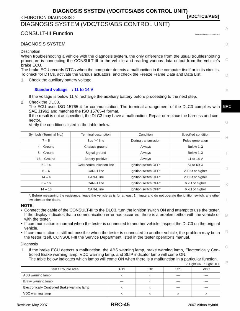
DescriptionWhen troubleshooting a vehicle with the diagnosis system, the only difference from the usual troubleshootingprocedure is connecting the CONSULT-III to the vehicle and reading various data output from the vehicle′sbrake ECU. The brake ECU records DTCs when the computer detects a malfunction in the computer itself or in its circuits.To check for DTCs, activate the various actuators, and check the Freeze Frame Data and Data List.1. Check the auxiliary battery voltage.
If the voltage is below 11 V, recharge the auxiliary battery before proceeding to the next step.2. Check the DLC3.
The ECU uses ISO 15765-4 for communication. The terminal arrangement of the DLC3 complies withSAE J1962 and matches the ISO 15765-4 format.If the result is not as specified, the DLC3 may have a malfunction. Repair or replace the harness and con-nector.Verify the conditions listed in the table below.
*: Before measuring the resistance, leave the vehicle as is for at least 1 minute and do not operate the ignition switch, any otherswitches or the doors.
NOTE:• Connect the cable of the CONSULT-III to the DLC3, turn the ignition switch ON and attempt to use the tester.
If the display indicates that a communication error has occurred, there is a problem either with the vehicle orwith the tester.
• If communication is normal when the tester is connected to another vehicle, inspect the DLC3 on the originalvehicle.
• If communication is still not possible when the tester is connected to another vehicle, the problem may be inthe tester itself. CONSULT-III the Service Department listed in the tester operator′s manual.
Diagnosis
1. If the brake ECU detects a malfunction, the ABS warning lamp, brake warning lamp, Electronically Con-trolled Brake warning lamp, VDC warning lamp, and SLIP indicator lamp will come ON.The table below indicates which lamps will come ON when there is a malfunction in a particular function.
×: Light ON –: Light OFF
Standard voltage : 11 to 14 V
Symbols (Terminal No.) Terminal description Condition Specified condition
7 – 5 Bus “+” line During transmission Pulse generation
4 – Ground Chassis ground Always Below 1 Ω
5 – Ground Signal ground Always Below 1 Ω
16 – Ground Battery positive Always 11 to 14 V
6 – 14 CAN communication line Ignition switch OFF* 54 to 69 Ω
6 – 4 CAN-H line Ignition switch OFF* 200 Ω or higher
14 – 4 CAN-L line Ignition switch OFF* 200 Ω or higher
6 – 16 CAN-H line Ignition switch OFF* 6 kΩ or higher
14 – 16 CAN-L line Ignition switch OFF* 6 kΩ or higher
Item / Trouble area ABS EBD TCS VDC
ABS warning lamp × × — —
Brake warning lamp — × — —
Electronically Controlled Brake warning lamp × × — —
VDC warning lamp × × × ×
BRC-45
[VDC/TCS/ABS]DIAGNOSIS SYSTEM (VDC/TCS/ABS CONTROL UNIT)
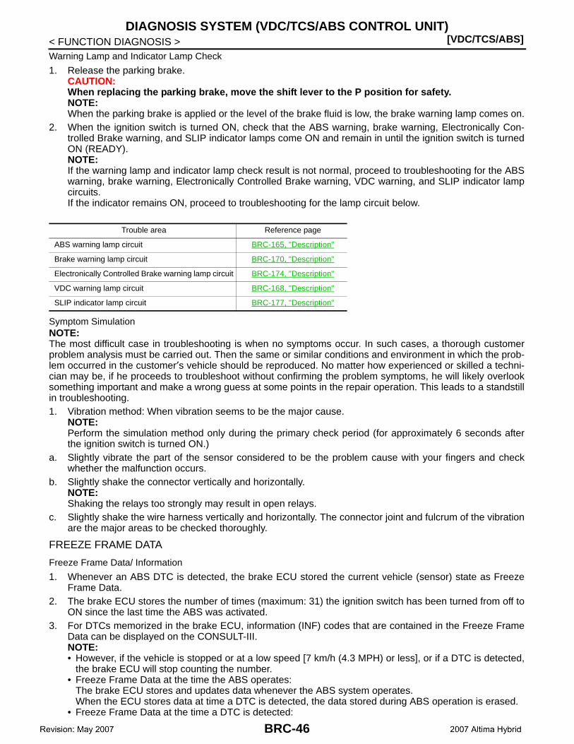
< FUNCTION DIAGNOSIS >Warning Lamp and Indicator Lamp Check
1. Release the parking brake.CAUTION:When replacing the parking brake, move the shift lever to the P position for safety.NOTE:When the parking brake is applied or the level of the brake fluid is low, the brake warning lamp comes on.
2. When the ignition switch is turned ON, check that the ABS warning, brake warning, Electronically Con-trolled Brake warning, and SLIP indicator lamps come ON and remain in until the ignition switch is turnedON (READY).NOTE:If the warning lamp and indicator lamp check result is not normal, proceed to troubleshooting for the ABSwarning, brake warning, Electronically Controlled Brake warning, VDC warning, and SLIP indicator lampcircuits.If the indicator remains ON, proceed to troubleshooting for the lamp circuit below.
Symptom SimulationNOTE:The most difficult case in troubleshooting is when no symptoms occur. In such cases, a thorough customerproblem analysis must be carried out. Then the same or similar conditions and environment in which the prob-lem occurred in the customer′s vehicle should be reproduced. No matter how experienced or skilled a techni-cian may be, if he proceeds to troubleshoot without confirming the problem symptoms, he will likely overlooksomething important and make a wrong guess at some points in the repair operation. This leads to a standstillin troubleshooting.1. Vibration method: When vibration seems to be the major cause.
NOTE:Perform the simulation method only during the primary check period (for approximately 6 seconds afterthe ignition switch is turned ON.)
a. Slightly vibrate the part of the sensor considered to be the problem cause with your fingers and checkwhether the malfunction occurs.
b. Slightly shake the connector vertically and horizontally.NOTE:Shaking the relays too strongly may result in open relays.
c. Slightly shake the wire harness vertically and horizontally. The connector joint and fulcrum of the vibrationare the major areas to be checked thoroughly.
FREEZE FRAME DATA
Freeze Frame Data/ Information
1. Whenever an ABS DTC is detected, the brake ECU stored the current vehicle (sensor) state as FreezeFrame Data.
2. The brake ECU stores the number of times (maximum: 31) the ignition switch has been turned from off toON since the last time the ABS was activated.
3. For DTCs memorized in the brake ECU, information (INF) codes that are contained in the Freeze FrameData can be displayed on the CONSULT-III.NOTE:• However, if the vehicle is stopped or at a low speed [7 km/h (4.3 MPH) or less], or if a DTC is detected,
the brake ECU will stop counting the number. • Freeze Frame Data at the time the ABS operates:
The brake ECU stores and updates data whenever the ABS system operates.When the ECU stores data at time a DTC is detected, the data stored during ABS operation is erased.
• Freeze Frame Data at the time a DTC is detected:
Trouble area Reference page
ABS warning lamp circuit BRC-165, "Description"
Brake warning lamp circuit BRC-170, "Description"
Electronically Controlled Brake warning lamp circuit BRC-174, "Description"
VDC warning lamp circuit BRC-168, "Description"
SLIP indicator lamp circuit BRC-177, "Description"
BRC-46
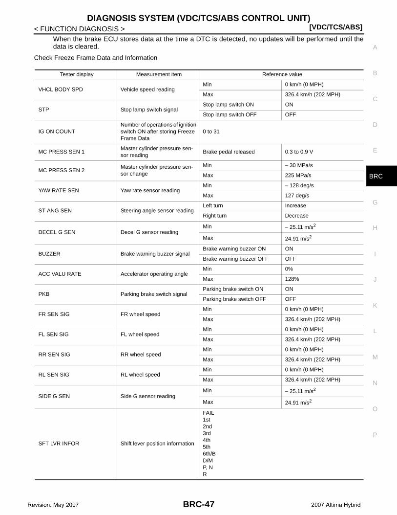
DIAGNOSIS SYSTEM (VDC/TCS/ABS CONTROL UNIT)[VDC/TCS/ABS]
C
D
E
G
H
I
J
K
L
M
A
B
RC
N
O
P
< FUNCTION DIAGNOSIS >
B
When the brake ECU stores data at the time a DTC is detected, no updates will be performed until thedata is cleared.
Check Freeze Frame Data and Information
Tester display Measurement item Reference value
VHCL BODY SPD Vehicle speed readingMin 0 km/h (0 MPH)
Max 326.4 km/h (202 MPH)
STP Stop lamp switch signalStop lamp switch ON ON
Stop lamp switch OFF OFF
IG ON COUNTNumber of operations of ignition switch ON after storing Freeze Frame Data
0 to 31
MC PRESS SEN 1Master cylinder pressure sen-sor reading
Brake pedal released 0.3 to 0.9 V
MC PRESS SEN 2Master cylinder pressure sen-sor change
Min − 30 MPa/s
Max 225 MPa/s
YAW RATE SEN Yaw rate sensor readingMin − 128 deg/s
Max 127 deg/s
ST ANG SEN Steering angle sensor readingLeft turn Increase
Right turn Decrease
DECEL G SEN Decel G sensor readingMin − 25.11 m/s2
Max 24.91 m/s2
BUZZER Brake warning buzzer signalBrake warning buzzer ON ON
Brake warning buzzer OFF OFF
ACC VALU RATE Accelerator operating angleMin 0%
Max 128%
PKB Parking brake switch signalParking brake switch ON ON
Parking brake switch OFF OFF
FR SEN SIG FR wheel speedMin 0 km/h (0 MPH)
Max 326.4 km/h (202 MPH)
FL SEN SIG FL wheel speedMin 0 km/h (0 MPH)
Max 326.4 km/h (202 MPH)
RR SEN SIG RR wheel speedMin 0 km/h (0 MPH)
Max 326.4 km/h (202 MPH)
RL SEN SIG RL wheel speedMin 0 km/h (0 MPH)
Max 326.4 km/h (202 MPH)
SIDE G SEN Side G sensor readingMin − 25.11 m/s2
Max 24.91 m/s2
SFT LVR INFOR Shift lever position information
FAIL1st2nd3rd4th5th6th/BD/MP, NR
BRC-47
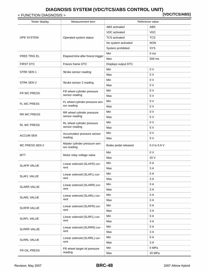
[VDC/TCS/ABS]DIAGNOSIS SYSTEM (VDC/TCS/ABS CONTROL UNIT)
< FUNCTION DIAGNOSIS >
OPE SYSTEM Operated system status
ABS activated ABS
VDC activated VDC
TCS activated TCS
No system activated NON
System prohibited SYS
FREE TRIG EL Elapsed time after freeze triggerMin 0 ms
Max 500 ms
FIRST DTC Freeze frame DTC Displays output DTC
STRK SEN 1 Stroke sensor readingMin 0 V
Max 5 V
STRK SEN 2 Stroke sensor 2 readingMin 0 V
Max 5 V
FR WC PRESSFR wheel cylinder pressure sensor reading
Min 0 V
Max 5 V
FL WC PRESSFL wheel cylinder pressure sen-sor reading
Min 0 V
Max 5 V
RR WC PRESSRR wheel cylinder pressure sensor reading
Min 0 V
Max 5 V
RL WC PRESSRL wheel cylinder pressure sensor reading
Min 0 V
Max 5 V
ACCUM SENAccumulator pressure sensor reading
Min 0 V
Max 5 V
MC PRESS SEN 2Master cylinder pressure sen-sor reading
Brake pedal released 0.3 to 0.9 V
MTT Motor relay voltage valueMin 0 V
Max 20 V
SLAFR VALUELinear solenoid (SLAFR) cur-rent
Min 0 A
Max 3 A
SLAFL VALUELinear solenoid (SLAFL) cur-rent
Min 0 A
Max 3 A
SLARR VALUELinear solenoid (SLARR) cur-rent
Min 0 A
Max 3 A
SLARL VALUELinear solenoid (SLARL) cur-rent
Min 0 A
Max 3 A
SLRFR VALUELinear solenoid (SLRFR) cur-rent
Min 0 A
Max 3 A
SLRFL VALUELinear solenoid (SLRFL) cur-rent
Min 0 A
Max 3 A
SLRRR VALUELinear solenoid (SLRRR) cur-rent
Min 0 A
Max 3 A
SLRRL VALUELinear solenoid (SLRRL) cur-rent
Min 0 A
Max 3 A
FR OIL PRESSFR wheel target oil pressure reading
Min 0 MPa
Max 20 MPa
Tester display Measurement item Reference value
BRC-48
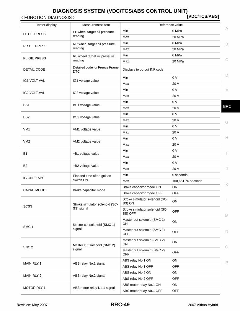
DIAGNOSIS SYSTEM (VDC/TCS/ABS CONTROL UNIT)[VDC/TCS/ABS]
C
D
E
G
H
I
J
K
L
M
A
B
RC
N
O
P
< FUNCTION DIAGNOSIS >
B
FL OIL PRESSFL wheel target oil pressure reading
Min 0 MPa
Max 20 MPa
RR OIL PRESSRR wheel target oil pressure reading
Min 0 MPa
Max 20 MPa
RL OIL PRESSRL wheel target oil pressure reading
Min 0 MPa
Max 20 MPa
DETAIL CODEDetailed code for Freeze Frame DTC
Displays to output INF code
IG1 VOLT VAL IG1 voltage valueMin 0 V
Max 20 V
IG2 VOLT VAL IG2 voltage valueMin 0 V
Max 20 V
BS1 BS1 voltage valueMin 0 V
Max 20 V
BS2 BS2 voltage valueMin 0 V
Max 20 V
VM1 VM1 voltage valueMin 0 V
Max 20 V
VM2 VM2 voltage valueMin 0 V
Max 20 V
B1 +B1 voltage valueMin 0 V
Max 20 V
B2 +B2 voltage valueMin 0 V
Max 20 V
IG ON ELAPSElapsed time after ignition switch ON
Min 0 seconds
Max 100,661.76 seconds
CAPAC MODE Brake capacitor modeBrake capacitor mode ON ON
Brake capacitor mode OFF OFF
SCSSStroke simulator solenoid (SC-SS) signal
Stroke simulator solenoid (SC-SS) ON
ON
Stroke simulator solenoid (SC-SS) OFF
OFF
SMC 1Master cut solenoid (SMC 1) signal
Master cut solenoid (SMC 1) ON
ON
Master cut solenoid (SMC 1) OFF
OFF
SNC 2Master cut solenoid (SMC 2) signal
Master cut solenoid (SMC 2) ON
ON
Master cut solenoid (SMC 2) OFF
OFF
MAIN RLY 1 ABS relay No.1 signalABS relay No.1 ON ON
ABS relay No.1 OFF OFF
MAIN RLY 2 ABS relay No.2 signalABS relay No.2 ON ON
ABS relay No.2 OFF OFF
MOTOR RLY 1 ABS motor relay No.1 signalABS motor relay No.1 ON ON
ABS motor relay No.1 OFF OFF
Tester display Measurement item Reference value
BRC-49

[VDC/TCS/ABS]DIAGNOSIS SYSTEM (VDC/TCS/ABS CONTROL UNIT)
< FUNCTION DIAGNOSIS >
Clear Freeze Frame Data and InformationCAUTION:Clearing the DTC will also clear the Freeze Frame Data and information (INF) cord.1. Connect the CONSULT-III.2. Turn the ignition switch ON.3. Clear the DTC and Freeze Frame Data. Refer to BRC-45, "CONSULT-III Function".
FAIL-SAFE CHART
Fail-Safe Function
1. If a malfunction occurs in the brake ECU, sensor signal, or actuator, rest normally operating parts willmaintain brake control.
2. When trouble occurs in the brake control system, the brake ECU turns the warning lamp ON, and prohibitsABS, TCS and VDC operations.
ABS, EBD and BA system:
NOTE:
A malfunction in the ABS system will result in an identical operation, with ABS, TCS and VDC system control prohibited.
TCS and VDC system:
NOTE:
As for the TCS and VDC systems, different systems prohibit different controls depending on a malfunctioning part.
3. The brake ECU prevents operation of a malfunctioning hydraulic pressure system and continues brakecontrol with the normal hydraulic pressure system.
MOTOR RLY 2 ABS motor relay 2 signalABS motor relay No.2 ON ON
ABS motor relay No.2 OFF OFF
RESERVOIR LVL Brake fluid level switch signalBrake fluid level switch ON ON
Brake fluid level switch OFF OFF
Tester display Measurement item Reference value
JSFIA0067GB
Malfunction area Control method
ABS system ABS, TCS and VDC control prohibited
EBD system ABS, EBD, TCS and VDC control prohibited
Malfunction area Control method
Hybrid control system(TCS and VDC systems)
Before control: Disables controlDuring control: Uses only the brakes to effect control
Brake control system(TCS and VDC systems)
Before control: Disables controlDuring control: Disables control (by gradually ending control)
BRC-50
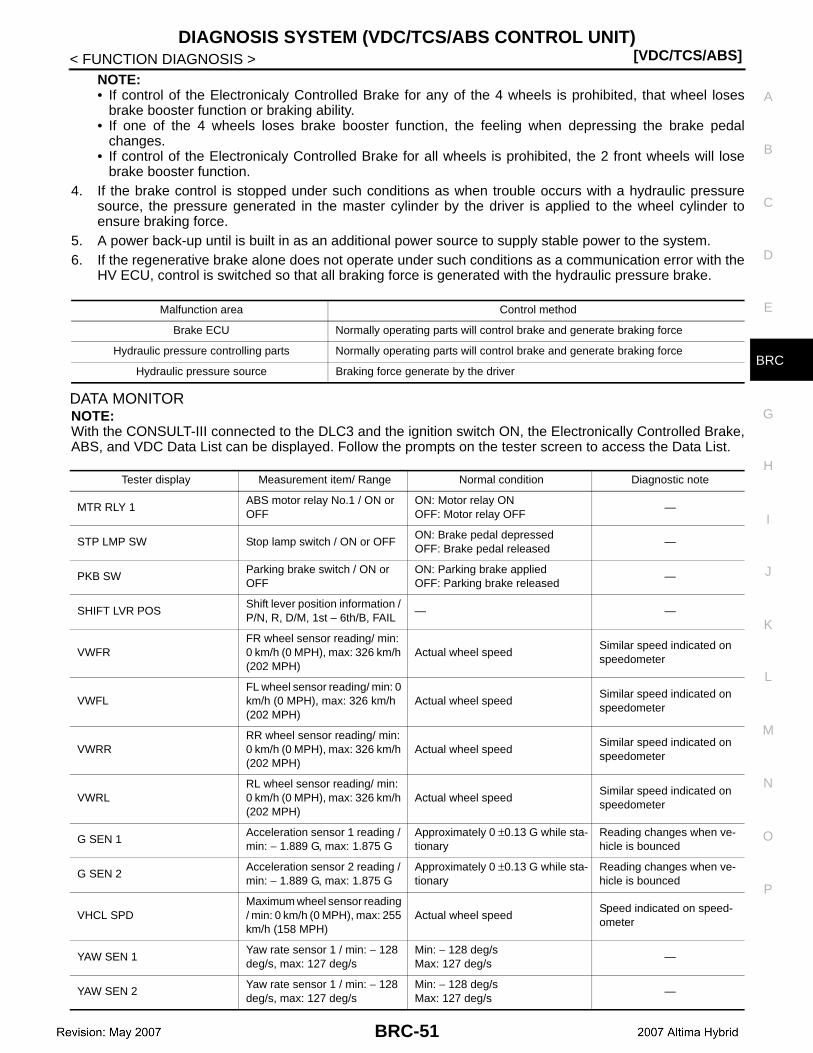
DIAGNOSIS SYSTEM (VDC/TCS/ABS CONTROL UNIT)[VDC/TCS/ABS]
C
D
E
G
H
I
J
K
L
M
A
B
RC
N
O
P
< FUNCTION DIAGNOSIS >
B
NOTE:• If control of the Electronicaly Controlled Brake for any of the 4 wheels is prohibited, that wheel loses
brake booster function or braking ability.• If one of the 4 wheels loses brake booster function, the feeling when depressing the brake pedal
changes.• If control of the Electronicaly Controlled Brake for all wheels is prohibited, the 2 front wheels will lose
brake booster function.4. If the brake control is stopped under such conditions as when trouble occurs with a hydraulic pressure
source, the pressure generated in the master cylinder by the driver is applied to the wheel cylinder toensure braking force.
5. A power back-up until is built in as an additional power source to supply stable power to the system.6. If the regenerative brake alone does not operate under such conditions as a communication error with the
HV ECU, control is switched so that all braking force is generated with the hydraulic pressure brake.
DATA MONITORNOTE:With the CONSULT-III connected to the DLC3 and the ignition switch ON, the Electronically Controlled Brake,ABS, and VDC Data List can be displayed. Follow the prompts on the tester screen to access the Data List.
Malfunction area Control method
Brake ECU Normally operating parts will control brake and generate braking force
Hydraulic pressure controlling parts Normally operating parts will control brake and generate braking force
Hydraulic pressure source Braking force generate by the driver
Tester display Measurement item/ Range Normal condition Diagnostic note
MTR RLY 1ABS motor relay No.1 / ON or OFF
ON: Motor relay ONOFF: Motor relay OFF
—
STP LMP SW Stop lamp switch / ON or OFFON: Brake pedal depressedOFF: Brake pedal released
—
PKB SWParking brake switch / ON or OFF
ON: Parking brake appliedOFF: Parking brake released
—
SHIFT LVR POSShift lever position information / P/N, R, D/M, 1st – 6th/B, FAIL
— —
VWFRFR wheel sensor reading/ min: 0 km/h (0 MPH), max: 326 km/h (202 MPH)
Actual wheel speedSimilar speed indicated on speedometer
VWFLFL wheel sensor reading/ min: 0 km/h (0 MPH), max: 326 km/h (202 MPH)
Actual wheel speedSimilar speed indicated on speedometer
VWRRRR wheel sensor reading/ min: 0 km/h (0 MPH), max: 326 km/h (202 MPH)
Actual wheel speedSimilar speed indicated on speedometer
VWRLRL wheel sensor reading/ min: 0 km/h (0 MPH), max: 326 km/h (202 MPH)
Actual wheel speedSimilar speed indicated on speedometer
G SEN 1Acceleration sensor 1 reading / min: − 1.889 G, max: 1.875 G
Approximately 0 ±0.13 G while sta-tionary
Reading changes when ve-hicle is bounced
G SEN 2Acceleration sensor 2 reading / min: − 1.889 G, max: 1.875 G
Approximately 0 ±0.13 G while sta-tionary
Reading changes when ve-hicle is bounced
VHCL SPDMaximum wheel sensor reading / min: 0 km/h (0 MPH), max: 255 km/h (158 MPH)
Actual wheel speedSpeed indicated on speed-ometer
YAW SEN 1Yaw rate sensor 1 / min: − 128 deg/s, max: 127 deg/s
Min: − 128 deg/sMax: 127 deg/s
—
YAW SEN 2Yaw rate sensor 1 / min: − 128 deg/s, max: 127 deg/s
Min: − 128 deg/sMax: 127 deg/s
—
BRC-51
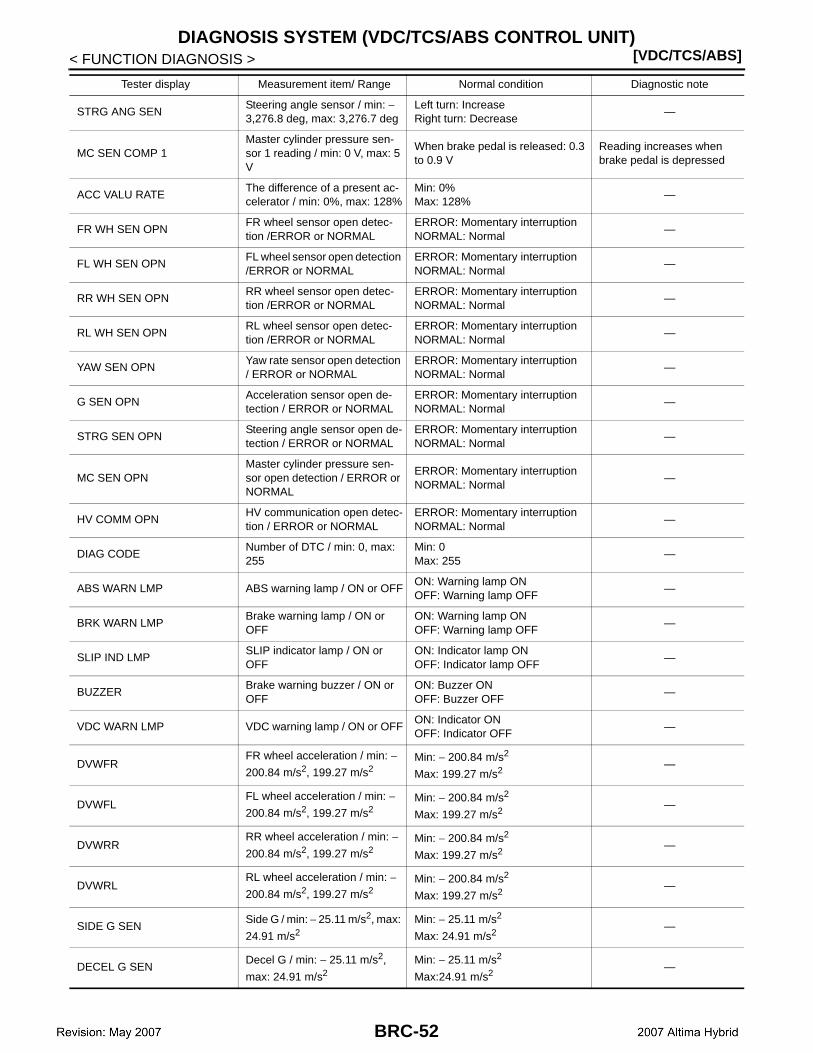
[VDC/TCS/ABS]DIAGNOSIS SYSTEM (VDC/TCS/ABS CONTROL UNIT)
< FUNCTION DIAGNOSIS >
STRG ANG SENSteering angle sensor / min: − 3,276.8 deg, max: 3,276.7 deg
Left turn: IncreaseRight turn: Decrease
—
MC SEN COMP 1Master cylinder pressure sen-sor 1 reading / min: 0 V, max: 5 V
When brake pedal is released: 0.3 to 0.9 V
Reading increases when brake pedal is depressed
ACC VALU RATEThe difference of a present ac-celerator / min: 0%, max: 128%
Min: 0%Max: 128%
—
FR WH SEN OPNFR wheel sensor open detec-tion /ERROR or NORMAL
ERROR: Momentary interruptionNORMAL: Normal
—
FL WH SEN OPNFL wheel sensor open detection /ERROR or NORMAL
ERROR: Momentary interruptionNORMAL: Normal
—
RR WH SEN OPNRR wheel sensor open detec-tion /ERROR or NORMAL
ERROR: Momentary interruptionNORMAL: Normal
—
RL WH SEN OPNRL wheel sensor open detec-tion /ERROR or NORMAL
ERROR: Momentary interruptionNORMAL: Normal
—
YAW SEN OPNYaw rate sensor open detection / ERROR or NORMAL
ERROR: Momentary interruptionNORMAL: Normal
—
G SEN OPNAcceleration sensor open de-tection / ERROR or NORMAL
ERROR: Momentary interruptionNORMAL: Normal
—
STRG SEN OPNSteering angle sensor open de-tection / ERROR or NORMAL
ERROR: Momentary interruptionNORMAL: Normal
—
MC SEN OPNMaster cylinder pressure sen-sor open detection / ERROR or NORMAL
ERROR: Momentary interruptionNORMAL: Normal
—
HV COMM OPNHV communication open detec-tion / ERROR or NORMAL
ERROR: Momentary interruptionNORMAL: Normal
—
DIAG CODENumber of DTC / min: 0, max: 255
Min: 0Max: 255
—
ABS WARN LMP ABS warning lamp / ON or OFFON: Warning lamp ONOFF: Warning lamp OFF
—
BRK WARN LMPBrake warning lamp / ON or OFF
ON: Warning lamp ONOFF: Warning lamp OFF
—
SLIP IND LMPSLIP indicator lamp / ON or OFF
ON: Indicator lamp ONOFF: Indicator lamp OFF
—
BUZZERBrake warning buzzer / ON or OFF
ON: Buzzer ONOFF: Buzzer OFF
—
VDC WARN LMP VDC warning lamp / ON or OFFON: Indicator ONOFF: Indicator OFF
—
DVWFRFR wheel acceleration / min: −
200.84 m/s2, 199.27 m/s2Min: − 200.84 m/s2
Max: 199.27 m/s2—
DVWFLFL wheel acceleration / min: −
200.84 m/s2, 199.27 m/s2Min: − 200.84 m/s2
Max: 199.27 m/s2—
DVWRRRR wheel acceleration / min: −
200.84 m/s2, 199.27 m/s2Min: − 200.84 m/s2
Max: 199.27 m/s2—
DVWRLRL wheel acceleration / min: −
200.84 m/s2, 199.27 m/s2Min: − 200.84 m/s2
Max: 199.27 m/s2—
SIDE G SENSide G / min: − 25.11 m/s2, max:
24.91 m/s2Min: − 25.11 m/s2
Max: 24.91 m/s2—
DECEL G SENDecel G / min: − 25.11 m/s2,
max: 24.91 m/s2Min: − 25.11 m/s2
Max:24.91 m/s2—
Tester display Measurement item/ Range Normal condition Diagnostic note
BRC-52
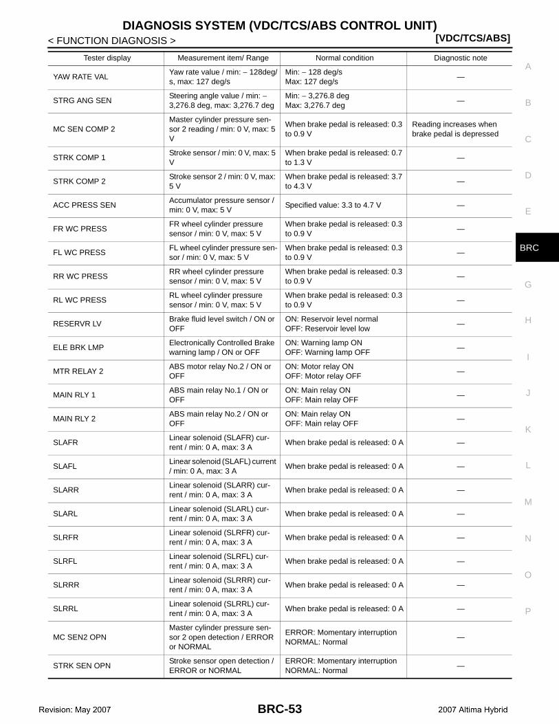
DIAGNOSIS SYSTEM (VDC/TCS/ABS CONTROL UNIT)[VDC/TCS/ABS]
C
D
E
G
H
I
J
K
L
M
A
B
RC
N
O
P
< FUNCTION DIAGNOSIS >
B
YAW RATE VALYaw rate value / min: − 128deg/s, max: 127 deg/s
Min: − 128 deg/sMax: 127 deg/s
—
STRG ANG SENSteering angle value / min: − 3,276.8 deg, max: 3,276.7 deg
Min: − 3,276.8 degMax: 3,276.7 deg
—
MC SEN COMP 2Master cylinder pressure sen-sor 2 reading / min: 0 V, max: 5 V
When brake pedal is released: 0.3 to 0.9 V
Reading increases when brake pedal is depressed
STRK COMP 1Stroke sensor / min: 0 V, max: 5 V
When brake pedal is released: 0.7 to 1.3 V
—
STRK COMP 2Stroke sensor 2 / min: 0 V, max: 5 V
When brake pedal is released: 3.7 to 4.3 V
—
ACC PRESS SENAccumulator pressure sensor / min: 0 V, max: 5 V
Specified value: 3.3 to 4.7 V —
FR WC PRESS FR wheel cylinder pressure sensor / min: 0 V, max: 5 V
When brake pedal is released: 0.3 to 0.9 V
—
FL WC PRESSFL wheel cylinder pressure sen-sor / min: 0 V, max: 5 V
When brake pedal is released: 0.3 to 0.9 V
—
RR WC PRESSRR wheel cylinder pressure sensor / min: 0 V, max: 5 V
When brake pedal is released: 0.3 to 0.9 V
—
RL WC PRESSRL wheel cylinder pressure sensor / min: 0 V, max: 5 V
When brake pedal is released: 0.3 to 0.9 V
—
RESERVR LVBrake fluid level switch / ON or OFF
ON: Reservoir level normalOFF: Reservoir level low
—
ELE BRK LMPElectronically Controlled Brake warning lamp / ON or OFF
ON: Warning lamp ONOFF: Warning lamp OFF
—
MTR RELAY 2ABS motor relay No.2 / ON or OFF
ON: Motor relay ONOFF: Motor relay OFF
—
MAIN RLY 1ABS main relay No.1 / ON or OFF
ON: Main relay ONOFF: Main relay OFF
—
MAIN RLY 2ABS main relay No.2 / ON or OFF
ON: Main relay ONOFF: Main relay OFF
—
SLAFRLinear solenoid (SLAFR) cur-rent / min: 0 A, max: 3 A
When brake pedal is released: 0 A —
SLAFLLinear solenoid (SLAFL) current / min: 0 A, max: 3 A
When brake pedal is released: 0 A —
SLARRLinear solenoid (SLARR) cur-rent / min: 0 A, max: 3 A
When brake pedal is released: 0 A —
SLARLLinear solenoid (SLARL) cur-rent / min: 0 A, max: 3 A
When brake pedal is released: 0 A —
SLRFRLinear solenoid (SLRFR) cur-rent / min: 0 A, max: 3 A
When brake pedal is released: 0 A —
SLRFLLinear solenoid (SLRFL) cur-rent / min: 0 A, max: 3 A
When brake pedal is released: 0 A —
SLRRRLinear solenoid (SLRRR) cur-rent / min: 0 A, max: 3 A
When brake pedal is released: 0 A —
SLRRLLinear solenoid (SLRRL) cur-rent / min: 0 A, max: 3 A
When brake pedal is released: 0 A —
MC SEN2 OPNMaster cylinder pressure sen-sor 2 open detection / ERROR or NORMAL
ERROR: Momentary interruptionNORMAL: Normal
—
STRK SEN OPNStroke sensor open detection / ERROR or NORMAL
ERROR: Momentary interruptionNORMAL: Normal
—
Tester display Measurement item/ Range Normal condition Diagnostic note
BRC-53
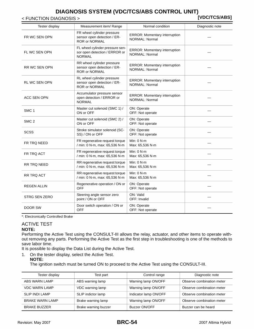
[VDC/TCS/ABS]DIAGNOSIS SYSTEM (VDC/TCS/ABS CONTROL UNIT)
< FUNCTION DIAGNOSIS >
*: Electronically Controlled Brake
ACTIVE TESTNOTE:Performing the Active Test using the CONSULT-III allows the relay, actuator, and other items to operate with-out removing any parts. Performing the Active Test as the first step in troubleshooting is one of the methods tosave labor time.It is possible to display the Data List during the Active Test.1. On the tester display, select the Active Test.
NOTE:The ignition switch must be turned ON to proceed to the Active Test using the CONSULT-III.
FR WC SEN OPNFR wheel cylinder pressure sensor open detection / ER-ROR or NORMAL
ERROR: Momentary interruptionNORMAL: Normal
—
FL WC SEN OPNFL wheel cylinder pressure sen-sor open detection / ERROR or NORMAL
ERROR: Momentary interruptionNORMAL: Normal
—
RR WC SEN OPNRR wheel cylinder pressure sensor open detection / ER-ROR or NORMAL
ERROR: Momentary interruptionNORMAL: Normal
—
RL WC SEN OPNRL wheel cylinder pressure sensor open detection / ER-ROR or NORMAL
ERROR: Momentary interruptionNORMAL: Normal
—
ACC SEN OPNAccumulator pressure sensor open detection / ERROR or NORMAL
ERROR: Momentary interruptionNORMAL: Normal
—
SMC 1Master cut solenoid (SMC 1) / ON or OFF
ON: OperateOFF: Not operate
—
SMC 2Master cut solenoid (SMC 2) / ON or OFF
ON: OperateOFF: Not operate
—
SCSSStroke simulator solenoid (SC-SS) / ON or OFF
ON: OperateOFF: Not operate
—
FR TRQ NEEDFR regenerative request torque / min: 0 N·m, max: 65,536 N·m
Min: 0 N·mMax: 65,536 N·m
—
FR TRQ ACTFR regenerative request torque / min: 0 N·m, max: 65,536 N·m
Min: 0 N·mMax: 65,536 N·m
—
RR TRQ NEEDRR regenerative request torque / min: 0 N·m, max: 65,536 N·m
Min: 0 N·mMax: 65,536 N·m
—
RR TRQ ACTRR regenerative request torque / min: 0 N·m, max: 65,536 N·m
Min: 0 N·mMax: 65,536 N·m
—
REGEN ALLINRegenerative operation / ON or OFF
ON: OperateOFF: Not operate
—
STRG SEN ZEROSteering angle sensor zero point / ON or OFF
ON: ValidOFF: Invalid
—
DOOR SWDoor switch operation / ON or OFF
ON: OperateOFF: Not operate
—
Tester display Measurement item/ Range Normal condition Diagnostic note
Tester display Test part Control range Diagnostic note
ABS WARN LAMP ABS warning lamp Warning lamp ON/OFF Observe combination meter
VDC WARN LAMP VDC warning lamp Warning lamp ON/OFF Observe combination meter
SLIP INDI LAMP SLIP indictor lamp Indicator lamp ON/OFF Observe combination meter
BRAKE WARN LAMP Brake warning lamp Warning lamp ON/OFF Observe combination meter
BRAKE BUZZER Brake warning buzzer Buzzer ON/OFF Buzzer can be heard
BRC-54
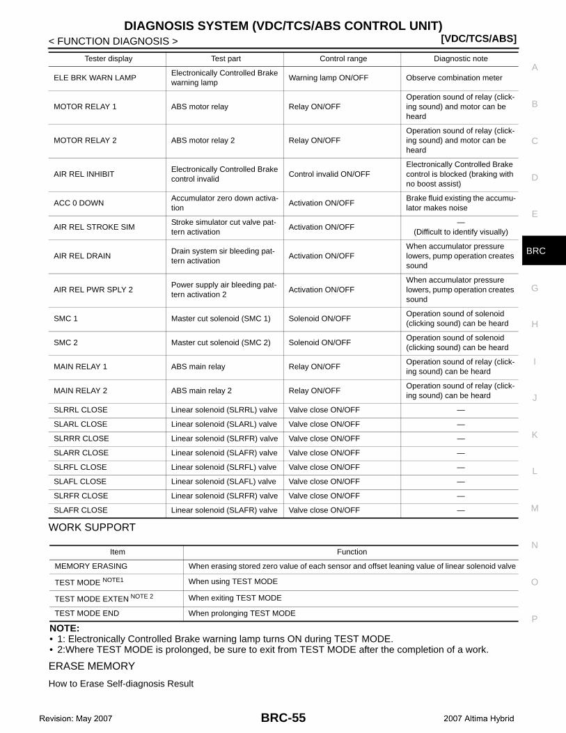
DIAGNOSIS SYSTEM (VDC/TCS/ABS CONTROL UNIT)[VDC/TCS/ABS]
C
D
E
G
H
I
J
K
L
M
A
B
RC
N
O
P
< FUNCTION DIAGNOSIS >
B
WORK SUPPORT
NOTE:• 1: Electronically Controlled Brake warning lamp turns ON during TEST MODE.• 2:Where TEST MODE is prolonged, be sure to exit from TEST MODE after the completion of a work.
ERASE MEMORY
How to Erase Self-diagnosis Result
ELE BRK WARN LAMPElectronically Controlled Brake warning lamp
Warning lamp ON/OFF Observe combination meter
MOTOR RELAY 1 ABS motor relay Relay ON/OFFOperation sound of relay (click-ing sound) and motor can be heard
MOTOR RELAY 2 ABS motor relay 2 Relay ON/OFFOperation sound of relay (click-ing sound) and motor can be heard
AIR REL INHIBITElectronically Controlled Brake control invalid
Control invalid ON/OFFElectronically Controlled Brake control is blocked (braking with no boost assist)
ACC 0 DOWNAccumulator zero down activa-tion
Activation ON/OFFBrake fluid existing the accumu-lator makes noise
AIR REL STROKE SIMStroke simulator cut valve pat-tern activation
Activation ON/OFF—
(Difficult to identify visually)
AIR REL DRAINDrain system sir bleeding pat-tern activation
Activation ON/OFFWhen accumulator pressure lowers, pump operation creates sound
AIR REL PWR SPLY 2Power supply air bleeding pat-tern activation 2
Activation ON/OFFWhen accumulator pressure lowers, pump operation creates sound
SMC 1 Master cut solenoid (SMC 1) Solenoid ON/OFFOperation sound of solenoid (clicking sound) can be heard
SMC 2 Master cut solenoid (SMC 2) Solenoid ON/OFFOperation sound of solenoid (clicking sound) can be heard
MAIN RELAY 1 ABS main relay Relay ON/OFFOperation sound of relay (click-ing sound) can be heard
MAIN RELAY 2 ABS main relay 2 Relay ON/OFFOperation sound of relay (click-ing sound) can be heard
SLRRL CLOSE Linear solenoid (SLRRL) valve Valve close ON/OFF —
SLARL CLOSE Linear solenoid (SLARL) valve Valve close ON/OFF —
SLRRR CLOSE Linear solenoid (SLRFR) valve Valve close ON/OFF —
SLARR CLOSE Linear solenoid (SLAFR) valve Valve close ON/OFF —
SLRFL CLOSE Linear solenoid (SLRFL) valve Valve close ON/OFF —
SLAFL CLOSE Linear solenoid (SLAFL) valve Valve close ON/OFF —
SLRFR CLOSE Linear solenoid (SLRFR) valve Valve close ON/OFF —
SLAFR CLOSE Linear solenoid (SLAFR) valve Valve close ON/OFF —
Tester display Test part Control range Diagnostic note
Item Function
MEMORY ERASING When erasing stored zero value of each sensor and offset leaning value of linear solenoid valve
TEST MODE NOTE1 When using TEST MODE
TEST MODE EXTEN NOTE 2 When exiting TEST MODE
TEST MODE END When prolonging TEST MODE
BRC-55
[VDC/TCS/ABS]DIAGNOSIS SYSTEM (VDC/TCS/ABS CONTROL UNIT)
< FUNCTION DIAGNOSIS >After erasing DTC memory, start engine and drive vehicle at 30 km/h (19 MPH) or more for approximately 1minute as the final inspection, and make sure that the VDC warning lamp, SLIP indicator lamp and Electroni-cally Controlled Brake warning lamp turn OFF.CAUTION:If memory cannot be erased, perform applicably diagnosis.
Erase Memory
1. Select “MEMORY ERASING” in “WORK SUPPORT” to erase memory of brake ECU.CAUTION:• Do not touch steering wheel while erasing memory.• When a memory is erased, stored value of zero point for each sensor and leaning value of linear
solenoid valve offset are also erased. Therefore, remember to perform zero adjustment for each sen-sor and initialization of linear solenoid valve.
- Steering angle sensor: BRC-9, "PERFORM ZERO POINT OF STEERING ANGLE SENSOR : Descrip-tion".
- Yaw rate/side/decel G sensor: BRC-8, "PERFORM ZERO POINT OF YAW RATE/SIDE/DECEL G SEN-SOR : Description".
- Stroke sensor: BRC-9, "PERFORM ADJUSTMENT OF STROKE SENSOR : Description".- Linear solenoid valve: BRC-7, "PERFORM INITIALIZATION OF LINEAR SOLENOID VALVE AND CALI-
BRATION : Description".• VDC warning lamp turns ON when stored zero point of steering angle sensor is erased. VDC warning
lamp turns OFF after performing zero adjustment for steering angle sensor. If VDC warning lampdoes not turn OFF, perform self-diagnosis for brake ECU.
BRC-56
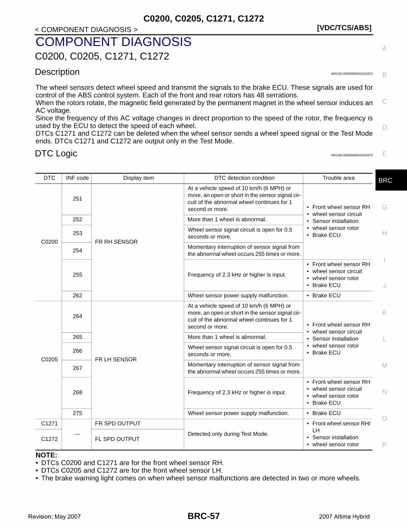
C0200, C0205, C1271, C1272[VDC/TCS/ABS]
C
D
E
G
H
I
J
K
L
M
A
B
RC
N
O
P
< COMPONENT DIAGNOSIS >
B
COMPONENT DIAGNOSISC0200, C0205, C1271, C1272
Description INFOID:0000000001501872
The wheel sensors detect wheel speed and transmit the signals to the brake ECU. These signals are used forcontrol of the ABS control system. Each of the front and rear rotors has 48 serrations.When the rotors rotate, the magnetic field generated by the permanent magnet in the wheel sensor induces anAC voltage.Since the frequency of this AC voltage changes in direct proportion to the speed of the rotor, the frequency isused by the ECU to detect the speed of each wheel.DTCs C1271 and C1272 can be deleted when the wheel sensor sends a wheel speed signal or the Test Modeends. DTCs C1271 and C1272 are output only in the Test Mode.
DTC Logic INFOID:0000000001501873
NOTE:• DTCs C0200 and C1271 are for the front wheel sensor RH.• DTCs C0205 and C1272 are for the front wheel sensor LH.• The brake warning light comes on when wheel sensor malfunctions are detected in two or more wheels.
DTC INF code Display item DTC detection condition Trouble area
C0200
251
FR RH SENSOR
At a vehicle speed of 10 km/h (6 MPH) or more, an open or short in the sensor signal cir-cuit of the abnormal wheel continues for 1 second or more. • Front wheel sensor RH
• wheel sensor circuit• Sensor installation• wheel sensor rotor• Brake ECU
252 More than 1 wheel is abnormal.
253Wheel sensor signal circuit is open for 0.5 seconds or more.
254Momentary interruption of sensor signal from the abnormal wheel occurs 255 times or more.
255 Frequency of 2.3 kHz or higher is input.
• Front wheel sensor RH• wheel sensor circuit• wheel sensor rotor• Brake ECU
262 Wheel sensor power supply malfunction. • Brake ECU
C0205
264
FR LH SENSOR
At a vehicle speed of 10 km/h (6 MPH) or more, an open or short in the sensor signal cir-cuit of the abnormal wheel continues for 1 second or more. • Front wheel sensor RH
• wheel sensor circuit• Sensor installation• wheel sensor rotor• Brake ECU
265 More than 1 wheel is abnormal.
266Wheel sensor signal circuit is open for 0.5 seconds or more.
267Momentary interruption of sensor signal from the abnormal wheel occurs 255 times or more.
268 Frequency of 2.3 kHz or higher is input.
• Front wheel sensor RH• wheel sensor circuit• wheel sensor rotor• Brake ECU
275 Wheel sensor power supply malfunction. • Brake ECU
C1271
—
FR SPD OUTPUT
Detected only during Test Mode.
• Front wheel sensor RH/LH
• Sensor installation• wheel sensor rotor
C1272 FL SPD OUTPUT
BRC-57
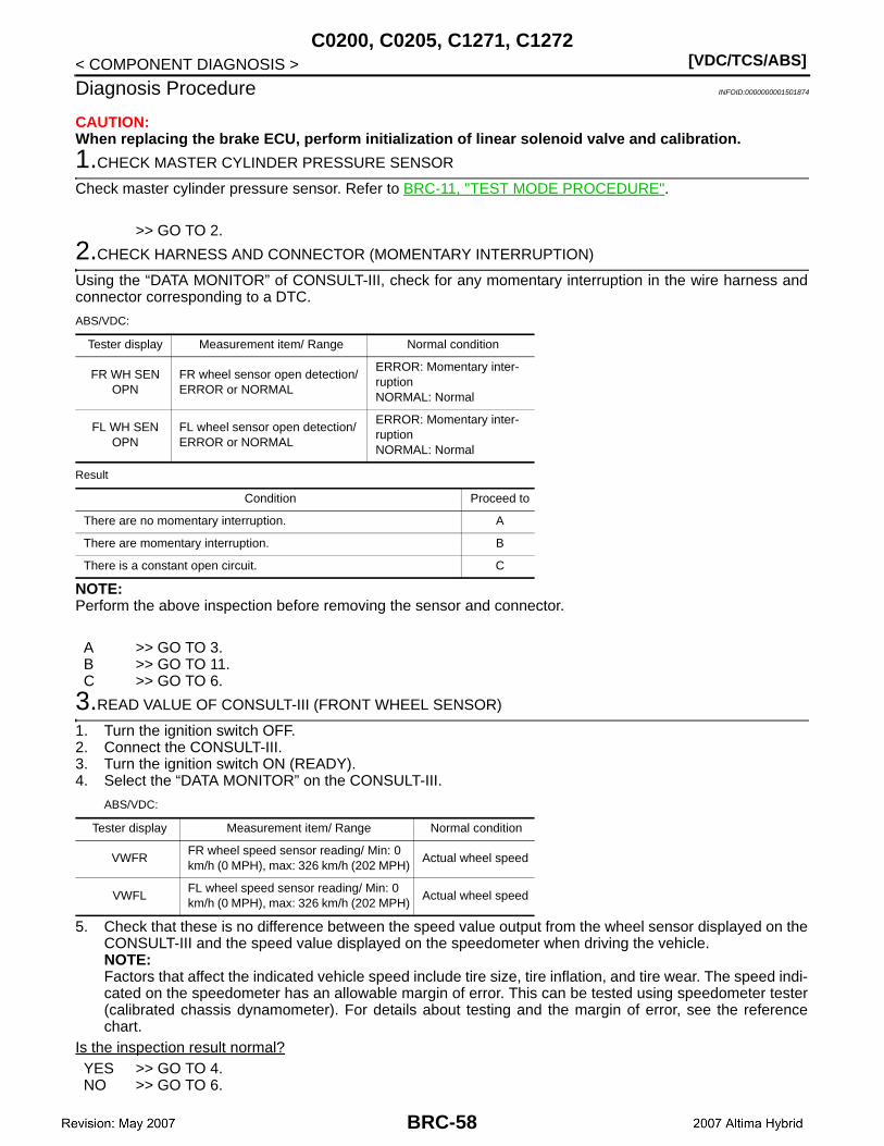
[VDC/TCS/ABS]C0200, C0205, C1271, C1272
< COMPONENT DIAGNOSIS >
Diagnosis Procedure INFOID:0000000001501874
CAUTION:When replacing the brake ECU, perform initialization of linear solenoid valve and calibration.
1.CHECK MASTER CYLINDER PRESSURE SENSOR
Check master cylinder pressure sensor. Refer to BRC-11, "TEST MODE PROCEDURE".
>> GO TO 2.
2.CHECK HARNESS AND CONNECTOR (MOMENTARY INTERRUPTION)
Using the “DATA MONITOR” of CONSULT-III, check for any momentary interruption in the wire harness andconnector corresponding to a DTC.
ABS/VDC:
Result
NOTE:Perform the above inspection before removing the sensor and connector.
A >> GO TO 3.B >> GO TO 11.C >> GO TO 6.
3.READ VALUE OF CONSULT-III (FRONT WHEEL SENSOR)
1. Turn the ignition switch OFF.2. Connect the CONSULT-III.3. Turn the ignition switch ON (READY).4. Select the “DATA MONITOR” on the CONSULT-III.
ABS/VDC:
5. Check that these is no difference between the speed value output from the wheel sensor displayed on theCONSULT-III and the speed value displayed on the speedometer when driving the vehicle.NOTE:Factors that affect the indicated vehicle speed include tire size, tire inflation, and tire wear. The speed indi-cated on the speedometer has an allowable margin of error. This can be tested using speedometer tester(calibrated chassis dynamometer). For details about testing and the margin of error, see the referencechart.
Is the inspection result normal?YES >> GO TO 4.NO >> GO TO 6.
Tester display Measurement item/ Range Normal condition
FR WH SEN OPN
FR wheel sensor open detection/ ERROR or NORMAL
ERROR: Momentary inter-ruptionNORMAL: Normal
FL WH SEN OPN
FL wheel sensor open detection/ ERROR or NORMAL
ERROR: Momentary inter-ruptionNORMAL: Normal
Condition Proceed to
There are no momentary interruption. A
There are momentary interruption. B
There is a constant open circuit. C
Tester display Measurement item/ Range Normal condition
VWFRFR wheel speed sensor reading/ Min: 0 km/h (0 MPH), max: 326 km/h (202 MPH)
Actual wheel speed
VWFLFL wheel speed sensor reading/ Min: 0 km/h (0 MPH), max: 326 km/h (202 MPH)
Actual wheel speed
BRC-58

C0200, C0205, C1271, C1272[VDC/TCS/ABS]
C
D
E
G
H
I
J
K
L
M
A
B
RC
N
O
P
< COMPONENT DIAGNOSIS >
B
4.PERFORM TEST MODE (SIGNAL CHECK)
Perform sensor check in the Test Mode procedure.Is the inspection result normal?YES >> GO TO 5.NO >> GO TO 6.
5.RECONFIRM DTC
1. Turn the ignition switch OFF.2. Clear the DTC.3. Turn the ignition switch ON (READY).4. Drive the vehicle at the speed of 32 km/h (20 MPH) or more for at least 60 seconds.5. Check if the same DTC is recorded.
Result
NOTE:If troubleshooting has been carried out according to the Problem Symptoms Table, Refer back to the tableand proceed to the next step.
A >> GO TO 6.B >> GO TO 8.
6.CHECK FRONT WHEEL SENSOR INSTALLATION
1. Turn the ignition switch OFF.2. Check the wheel sensor installation.Is an installation state normal?YES >> GO TO 7.NO >> Install front wheel sensor correctly.
7.CHECK FRONT WHEEL SENSOR TIP
1. Remove the front wheel sensor.2. Check the wheel sensor tip.
CAUTION:Check the wheel sensor signal after cleaning or replacement.
Is the inspection result normal?YES >> GO TO 8.NO >> Clean or replace front wheel sensor.
8.INSPECT FRONT WHEEL SENSOR
1. Turn the ignition switch OFF.2. Install the front wheel sensor.3. Disconnect the front wheel sensor connector.4. Measure the resistance according to the value(s) in the table below.
Condition Proceed to
DTCs (C0200 and/or C0205) are not output. A
DTCs (C0200 and/or C0205) are output. B
Front RH wheel sensorCondition Specified condition
Connector Terminal
E41 1 – 2 Always Not existed
E41 1 – Ground Always Existed
E41 2 – Ground Always Existed
BRC-59

[VDC/TCS/ABS]C0200, C0205, C1271, C1272
< COMPONENT DIAGNOSIS >
NOTE:Check the wheel sensor signal after replacement.
Is the inspection result normal?YES >> GO TO 9.NO >> Replace front wheel sensor.
9.CHECK HARNESS AND CONNECTOR (BRAKE ECU – FRONT WHEEL SENSOR)
1. Disconnect the brake ECU connectors.2. Measure the resistance according to the value(s) in the table below.
RH
LH
Is the inspection result normal?YES >> GO TO 10.NO >> Repair or replace harness or connector.
10.RECONFIRM DTC
1. Turn ignition switch OFF.2. Clear the DTC.3. Turn the ignition switch ON (READY).4. Drive the vehicle at the speed of 32 km/h (20 MPH) or more for at least 60 seconds.5. Check if the same DTC is recorded.
Result
NOTE:If troubleshooting has been carried out according to the Problem Symptoms Table, refer back to the tableand proceed to the next step.
A >> Check for intermittent problems (symptom simulation).B >> Replace brake ECU.
11.REPAIR OR REPLACE HARNESS OR CONNECTOR
Front LH wheel sensorCondition Specified condition
Connector Terminal
E19 1 – 2 Always Not existed
E19 1 – Ground Always Existed
E19 2 – Ground Always Existed
Brake ECU Wheel sensor— Condition Specified condition
Connector Terminal Connector Terminal
E60 30 E41 1 — Always Below 1 Ω
E60 30 — — Ground Always 10 kΩ or higher
E60 17 E41 2 — Always Below 1 Ω
E60 17 — — Ground Always 10 kΩ or higher
Brake ECU Wheel sensor— Condition Specified condition
Connector Terminal Connector Terminal
E61 76 E19 1 — Always Below 1 Ω
E61 76 — — Ground Always 10 kΩ or higher
E61 64 E19 2 — Always Below 1 Ω
E61 64 — — Ground Always 10 kΩ or higher
Condition Proceed to
DTCs (C0200 and/or C0205) are not output. A
DTCs (C0200 and/or C0205) are output. B
BRC-60

C0200, C0205, C1271, C1272[VDC/TCS/ABS]
C
D
E
G
H
I
J
K
L
M
A
B
RC
N
O
P
< COMPONENT DIAGNOSIS >
B
1. Turn ignition switch OFF.2. Repair or replace the harness or connector.3. Check for any momentary interruption between the brake ECU and front wheel sensor.4. Check that there is no momentary interruption.
>> GO TO 12.
12.RECONFIRM DTC
1. Turn ignition switch OFF.2. Clear the DTC.3. Turn ignition switch ON (READY).4. Drive the vehicle at the speed of 32 km/h (20 MPH) or more for at least 60 seconds.5. Check if the same DTC is recorded.
Result
A >> INSPECTION ENDB >> GO TO 1.
Special Repair Requirement INFOID:0000000001501875
1.ZERO ADJUSTMENT FOR EACH SENSOR AND OFFSET LEANING FOR LINEAR SOLENOID VALVE
After erasing brake ECU memories, perform zero adjustment of following sensors and initialization of linearsolenoid valve.• Steering angle sensor: BRC-9, "PERFORM ZERO POINT OF STEERING ANGLE SENSOR : Description".• Yaw rate/side/decel G sensor: BRC-8, "PERFORM ZERO POINT OF YAW RATE/SIDE/DECEL G SENSOR
: Description".• Brake stroke sensor: BRC-9, "PERFORM ADJUSTMENT OF STROKE SENSOR : Description".• Linear solenoid valve: BRC-7, "PERFORM INITIALIZATION OF LINEAR SOLENOID VALVE AND CALI-
BRATION : Description".
>> END
Condition Proceed to
DTCs (C0200 and/or C0205) are not output. A
DTCs (C0200 and/or C0205) are output. B
BRC-61
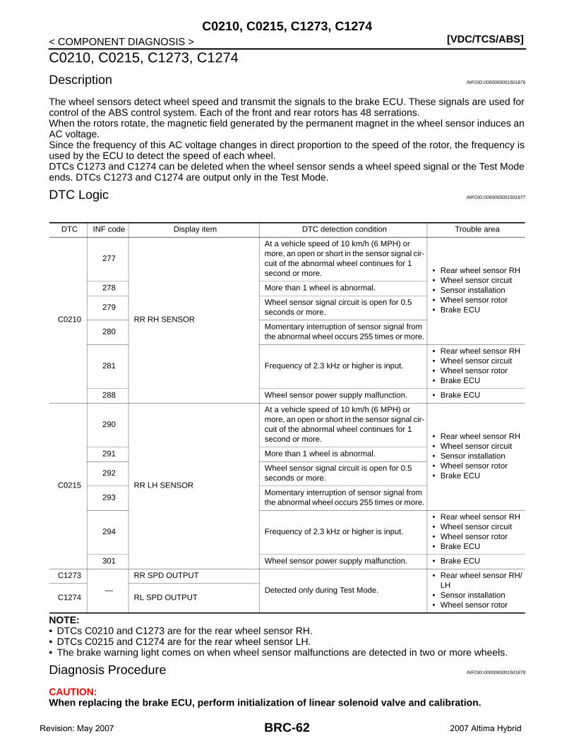
[VDC/TCS/ABS]C0210, C0215, C1273, C1274
< COMPONENT DIAGNOSIS >
C0210, C0215, C1273, C1274
Description INFOID:0000000001501876
The wheel sensors detect wheel speed and transmit the signals to the brake ECU. These signals are used forcontrol of the ABS control system. Each of the front and rear rotors has 48 serrations.When the rotors rotate, the magnetic field generated by the permanent magnet in the wheel sensor induces anAC voltage.Since the frequency of this AC voltage changes in direct proportion to the speed of the rotor, the frequency isused by the ECU to detect the speed of each wheel.DTCs C1273 and C1274 can be deleted when the wheel sensor sends a wheel speed signal or the Test Modeends. DTCs C1273 and C1274 are output only in the Test Mode.
DTC Logic INFOID:0000000001501877
NOTE:• DTCs C0210 and C1273 are for the rear wheel sensor RH.• DTCs C0215 and C1274 are for the rear wheel sensor LH.• The brake warning light comes on when wheel sensor malfunctions are detected in two or more wheels.
Diagnosis Procedure INFOID:0000000001501878
CAUTION:When replacing the brake ECU, perform initialization of linear solenoid valve and calibration.
DTC INF code Display item DTC detection condition Trouble area
C0210
277
RR RH SENSOR
At a vehicle speed of 10 km/h (6 MPH) or more, an open or short in the sensor signal cir-cuit of the abnormal wheel continues for 1 second or more. • Rear wheel sensor RH
• Wheel sensor circuit• Sensor installation• Wheel sensor rotor• Brake ECU
278 More than 1 wheel is abnormal.
279Wheel sensor signal circuit is open for 0.5 seconds or more.
280Momentary interruption of sensor signal from the abnormal wheel occurs 255 times or more.
281 Frequency of 2.3 kHz or higher is input.
• Rear wheel sensor RH• Wheel sensor circuit• Wheel sensor rotor• Brake ECU
288 Wheel sensor power supply malfunction. • Brake ECU
C0215
290
RR LH SENSOR
At a vehicle speed of 10 km/h (6 MPH) or more, an open or short in the sensor signal cir-cuit of the abnormal wheel continues for 1 second or more. • Rear wheel sensor RH
• Wheel sensor circuit• Sensor installation• Wheel sensor rotor• Brake ECU
291 More than 1 wheel is abnormal.
292Wheel sensor signal circuit is open for 0.5 seconds or more.
293Momentary interruption of sensor signal from the abnormal wheel occurs 255 times or more.
294 Frequency of 2.3 kHz or higher is input.
• Rear wheel sensor RH• Wheel sensor circuit• Wheel sensor rotor• Brake ECU
301 Wheel sensor power supply malfunction. • Brake ECU
C1273
—
RR SPD OUTPUT
Detected only during Test Mode.
• Rear wheel sensor RH/LH
• Sensor installation• Wheel sensor rotor
C1274 RL SPD OUTPUT
BRC-62

C0210, C0215, C1273, C1274[VDC/TCS/ABS]
C
D
E
G
H
I
J
K
L
M
A
B
RC
N
O
P
< COMPONENT DIAGNOSIS >
B
1.CHECK MASTER CYLINDER PRESSURE SENSOR
Check master cylinder pressure sensor. Refer to BRC-11, "TEST MODE PROCEDURE".
>> GO TO 2.
2.CHECK HARNESS AND CONNECTOR (MOMENTARY INTERRUPTION)
Using the “DATA MONITOR” of CONSULT-III, check for any momentary interruption in the wire harness andconnector corresponding to a DTC.
ABS/VDC:
Result
NOTE:Perform the above inspection before removing the sensor and connector.
A >> GO TO 3.B >> GO TO 11.C >> GO TO 6.
3.READ VALUE OF CONSULT-III (REAR WHEEL SENSOR)
1. Turn the ignition switch OFF.2. Connect the CONSULT-III.3. Turn the ignition switch ON (READY).4. Select the “DATA MONITOR” on the CONSULT-III.
ABS/VDC:
5. Check that these is no difference between the speed value output from the wheel sensor displayed on theCONSULT-III and the speed value displayed on the speedometer when driving the vihicle.NOTE:Factors that affect the indicated vehicle speed include tire size, tire inflation, and tire wear. The speed indi-cated on the speedometer has an allowable margin of error. This can be tested using speedometer tester(calibrated chassis dynamometer). For details about testing and the margin of error, see the referencechart.
Is the inspection result normal?YES >> GO TO 4.NO >> GO TO 6.
4.PERFORM TEST MODE (SIGNAL CHECK)
Perform sensor check in the Test Mode procedure.Is the inspection result normal?
Tester display Measurement item/ Range Normal condition
RR WH SEN OPN
RR wheel sensor open detection/ ERROR or NORMAL
ERROR: Momentary inter-ruptionNORMAL: Normal
RL WH SEN OPN
RL wheel sensor open detection/ ERROR or NORMAL
ERROR: Momentary inter-ruptionNORMAL: Normal
Condition Proceed to
There are no momentary interruption. A
There are momentary interruption. B
There is a constant open circuit. C
Tester display Measurement item/ Range Normal condition
VWRRRR wheel speed sensor reading/ Min: 0 km/h (0 MPH), max: 326 km/h (202 MPH)
Actual wheel speed
VWRLRL wheel speed sensor reading/ Min: 0 km/h (0 MPH), max: 326 km/h (202 MPH)
Actual wheel speed
BRC-63
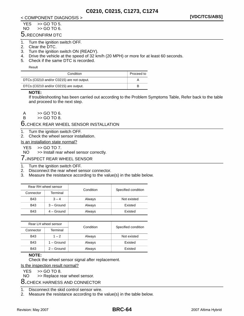
[VDC/TCS/ABS]C0210, C0215, C1273, C1274
< COMPONENT DIAGNOSIS >YES >> GO TO 5.NO >> GO TO 6.
5.RECONFIRM DTC
1. Turn the ignition switch OFF.2. Clear the DTC.3. Turn the ignition switch ON (READY).4. Drive the vehicle at the speed of 32 km/h (20 MPH) or more for at least 60 seconds.5. Check if the same DTC is recorded.
Result
NOTE:If troubleshooting has been carried out according to the Problem Symptoms Table, Refer back to the tableand proceed to the next step.
A >> GO TO 6.B >> GO TO 8.
6.CHECK REAR WHEEL SENSOR INSTALLATION
1. Turn the ignition switch OFF.2. Check the wheel sensor installation.Is an installation state normal?YES >> GO TO 7.NO >> Install rear wheel sensor correctly.
7.INSPECT REAR WHEEL SENSOR
1. Turn the ignition switch OFF.2. Disconnect the rear wheel sensor connector.3. Measure the resistance according to the value(s) in the table below.
NOTE:Check the wheel sensor signal after replacement.
Is the inspection result normal?YES >> GO TO 8.NO >> Replace rear wheel sensor.
8.CHECK HARNESS AND CONNECTOR
1. Disconnect the skid control sensor wire.2. Measure the resistance according to the value(s) in the table below.
Condition Proceed to
DTCs (C0210 and/or C0215) are not output. A
DTCs (C0210 and/or C0215) are output. B
Rear RH wheel sensorCondition Specified condition
Connector Terminal
B43 3 – 4 Always Not existed
B43 3 – Ground Always Existed
B43 4 – Ground Always Existed
Rear LH wheel sensorCondition Specified condition
Connector Terminal
B43 1 – 2 Always Not existed
B43 1 – Ground Always Existed
B43 2 – Ground Always Existed
BRC-64

C0210, C0215, C1273, C1274[VDC/TCS/ABS]
C
D
E
G
H
I
J
K
L
M
A
B
RC
N
O
P
< COMPONENT DIAGNOSIS >
B
RH
LH
NOTE:Check the wheel sensor signal after replacement.
Is the inspection result normal?YES >> GO TO 9.NO >> Replace skid control sensor wire.
9.CHECK HARNESS AND CONNECTOR (BRAKE ECU – REAR WHEEL SENSOR)
1. Disconnect the brake ECU connectors.2. Measure the resistance according to the value(s) in the table below.
RH
LH
Is the inspection result normal?YES >> GO TO 10.NO >> Repair or replace harness or connector.
10.RECONFIRM DTC
1. Turn ignition switch OFF.2. Clear the DTC.3. Turn the ignition switch ON (READY).4. Drive the vehicle at the speed of 32 km/h (20 MPH) or more for at least 60 seconds.5. Check if the same DTC is recorded.
Sensor side Vehicle side Condition Specified condition
3 5 Always Below 1 Ω
3 14 Always 10 kΩ or higher
3 Ground Always 10 kΩ or higher
4 14 Always Below 1 Ω
4 5 Always 10 kΩ or higher
4 Ground Always 10 kΩ or higher
Sensor side Vehicle side Condition Specified condition
1 4 Always Below 1 Ω
1 13 Always 10 kΩ or higher
1 Ground Always 10 kΩ or higher
2 13 Always Below 1 Ω
2 4 Always 10 kΩ or higher
2 Ground Always 10 kΩ or higher
Brake ECU Wheel sensor— Condition Specified condition
Connector Terminal Connector Terminal
E61 79 B43 3 — Always Below 1 Ω
E61 79 — — Ground Always 10 kΩ or higher
E61 66 B43 4 — Always Below 1 Ω
E61 66 — — Ground Always 10 kΩ or higher
Brake ECU Wheel sensor— Condition Specified condition
Connector Terminal Connector Terminal
E60 34 B43 1 — Always Below 1 Ω
E60 34 — — Ground Always 10 kΩ or higher
E60 33 B43 2 — Always Below 1 Ω
E60 33 — — Ground Always 10 kΩ or higher
BRC-65

[VDC/TCS/ABS]C0210, C0215, C1273, C1274
< COMPONENT DIAGNOSIS >Result
NOTE:If troubleshooting has been carried out according to the Problem Symptoms Table, refer back to the tableand proceed to the next step.
A >> Check for intermittent problems (symtom simulation).B >> Replace brake ECU.
11.REPAIR OR REPLACE HARNESS OR CONNECTOR (BRAKE ECU – REAR WHEEL SENSOR)
1. Turn ignition switch OFF.2. Repair or replace the harness or connector.3. Check for any momentary interruption between the brake ECU and rear wheel sensor.4. Check that there is no momentary interruption.
>> GO TO 12.
12.RECONFIRM DTC
1. Turn ignition switch OFF.2. Clear the DTC.3. Turn ignition switch ON (READY).4. Drive the vehicle at the speed of 32 km/h (20 MPH) or more for at least 60 seconds.5. Check if the same DTC is recorded.
Result
A >> INSPECTION ENDB >> GO TO 1.
Special Repair Requirement INFOID:0000000001501879
1.ZERO ADJUSTMENT FOR EACH SENSOR AND OFFSET LEANING FOR LINEAR SOLENOID VALVE
After erasing brake ECU memories, perform zero adjustment of following sensors and initialization of linearsolenoid valve.• Steering angle sensor: BRC-9, "PERFORM ZERO POINT OF STEERING ANGLE SENSOR : Description".• Yaw rate/side/decel G sensor: BRC-8, "PERFORM ZERO POINT OF YAW RATE/SIDE/DECEL G SENSOR
: Description".• Brake stroke sensor: BRC-9, "PERFORM ADJUSTMENT OF STROKE SENSOR : Description".• Linear solenoid valve: BRC-7, "PERFORM INITIALIZATION OF LINEAR SOLENOID VALVE AND CALI-
BRATION : Description".
>> END
Condition Proceed to
DTCs (C0210 and/or C0215) are not output. A
DTCs (C0210 and/or C0215) are output. B
Condition Proceed to
DTCs (C0210 and/or C0215) are not output. A
DTCs (C0210 and/or C0215) are output. B
BRC-66
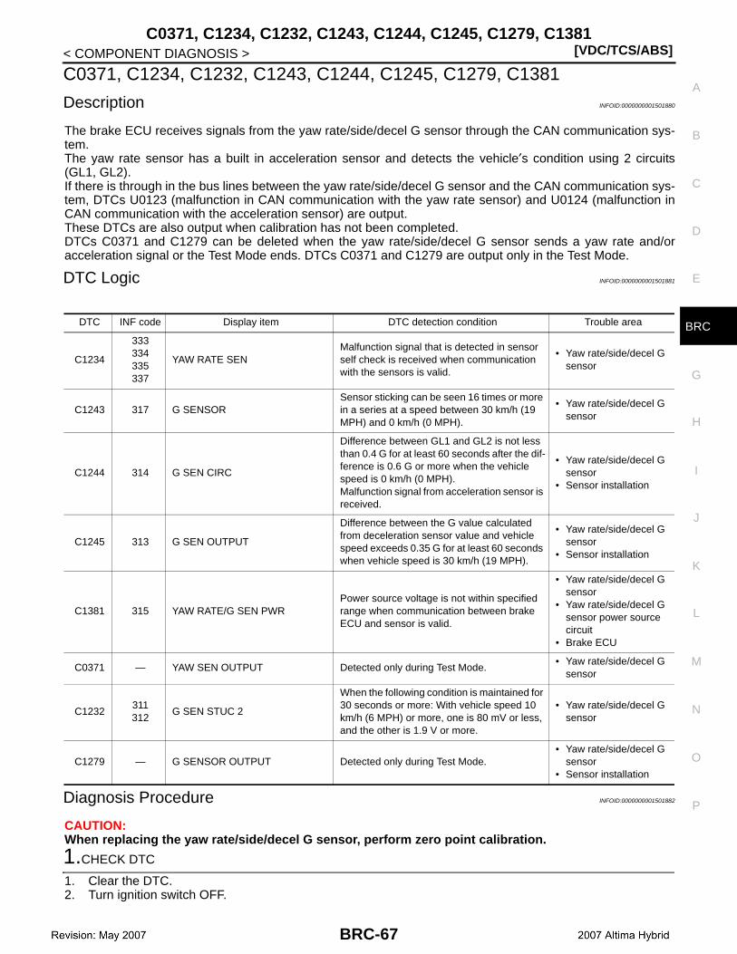
C0371, C1234, C1232, C1243, C1244, C1245, C1279, C1381[VDC/TCS/ABS]
C
D
E
G
H
I
J
K
L
M
A
B
RC
N
O
P
< COMPONENT DIAGNOSIS >
B
C0371, C1234, C1232, C1243, C1244, C1245, C1279, C1381
Description INFOID:0000000001501880
The brake ECU receives signals from the yaw rate/side/decel G sensor through the CAN communication sys-tem.The yaw rate sensor has a built in acceleration sensor and detects the vehicle′s condition using 2 circuits(GL1, GL2).If there is through in the bus lines between the yaw rate/side/decel G sensor and the CAN communication sys-tem, DTCs U0123 (malfunction in CAN communication with the yaw rate sensor) and U0124 (malfunction inCAN communication with the acceleration sensor) are output.These DTCs are also output when calibration has not been completed.DTCs C0371 and C1279 can be deleted when the yaw rate/side/decel G sensor sends a yaw rate and/oracceleration signal or the Test Mode ends. DTCs C0371 and C1279 are output only in the Test Mode.
DTC Logic INFOID:0000000001501881
Diagnosis Procedure INFOID:0000000001501882
CAUTION:When replacing the yaw rate/side/decel G sensor, perform zero point calibration.
1.CHECK DTC
1. Clear the DTC.2. Turn ignition switch OFF.
DTC INF code Display item DTC detection condition Trouble area
C1234
333334335337
YAW RATE SENMalfunction signal that is detected in sensor self check is received when communication with the sensors is valid.
• Yaw rate/side/decel G sensor
C1243 317 G SENSORSensor sticking can be seen 16 times or more in a series at a speed between 30 km/h (19 MPH) and 0 km/h (0 MPH).
• Yaw rate/side/decel G sensor
C1244 314 G SEN CIRC
Difference between GL1 and GL2 is not less than 0.4 G for at least 60 seconds after the dif-ference is 0.6 G or more when the vehicle speed is 0 km/h (0 MPH).Malfunction signal from acceleration sensor is received.
• Yaw rate/side/decel G sensor
• Sensor installation
C1245 313 G SEN OUTPUT
Difference between the G value calculated from deceleration sensor value and vehicle speed exceeds 0.35 G for at least 60 seconds when vehicle speed is 30 km/h (19 MPH).
• Yaw rate/side/decel G sensor
• Sensor installation
C1381 315 YAW RATE/G SEN PWRPower source voltage is not within specified range when communication between brake ECU and sensor is valid.
• Yaw rate/side/decel G sensor
• Yaw rate/side/decel G sensor power source circuit
• Brake ECU
C0371 — YAW SEN OUTPUT Detected only during Test Mode.• Yaw rate/side/decel G
sensor
C1232311312
G SEN STUC 2
When the following condition is maintained for 30 seconds or more: With vehicle speed 10 km/h (6 MPH) or more, one is 80 mV or less, and the other is 1.9 V or more.
• Yaw rate/side/decel G sensor
C1279 — G SENSOR OUTPUT Detected only during Test Mode.• Yaw rate/side/decel G
sensor• Sensor installation
BRC-67

[VDC/TCS/ABS]C0371, C1234, C1232, C1243, C1244, C1245, C1279, C1381
< COMPONENT DIAGNOSIS >3. At a speed of 30 km/h (19 MPH) or more, drive the vehicle, turn the steering wheel, and decelerate the
vehicle (depress the brake pedal).4. Turn the ignition switch ON again and check that no CAN communication system DTC is output.5. Check if DTCs indicating that zero point calibration of the yaw rate sensor is undone (C11A0) or indicating
that zero point calibration of the acceleration sensor is undone (C1336) are output.
Result
A >> GO TO 2.B >> Inspect CAN communication systemC >> Repair circuit indicated by output DTC.
2.CHECK YAW RATE/SIDE/DECEL G SENSOR INSTALLATION
1. Turn the ignition switch OFF.2. Check that the yaw rate/side/decel G sensor has been installed properly.Is the inspection result normal?YES >> GO TO 3.NO >> Install yaw rate/side/decel G sensor correctly.
3.INSPECT YAW RATE/SIDE/DECEL G SENSOR (IG TERMINAL)
1. Disconnect the yaw rate/side/decel G sensor connector.2. Turn ignition switch ON.3. Measure the voltage according to the value(s) in the table below.
Is the inspection result normal?YES >> GO TO 4.NO >> Repair or replace harness or connector (IG circuit).
4.INSPECT YAW RATE/SIDE/DECEL G SENSOR (GND TERMINAL)
1. Turn ignition switch OFF.2. Measure the resistance according to the value(s) in the table below.
CAUTION:Check the yaw rate/side/decel G sensor signal after replacement.NOTE:If troubleshooting has been carried out according to the Problem Symptoms Table, refer back to the tableand proceed to the next stop.
Is the inspection result normal?YES >> Replace yaw rate/side/decel G sensor.NO >> Repair or replace harness or connector (GND circuit).
Special Repair Requirement INFOID:0000000001501883
1.ZERO ADJUSTMENT FOR EACH SENSOR AND OFFSET LEANING FOR LINEAR SOLENOID VALVE
Condition Proceed to
DTCs (C11A0. C1336, and/or CAN communication system DTC) are not output.
A
CAN communication system DTC is output. B
DTCs (C11A0 and/or C1336) are output. C
Yaw rate/side/decel G sensorCondition Specified condition
Connector Terminal
M55 3 – Ground Ignition switch ON 10 to 14 V
Yaw rate/side/decel G sensorCondition Specified condition
Connector Terminal
M55 1 – Ground Always Below 1 Ω
BRC-68

C0371, C1234, C1232, C1243, C1244, C1245, C1279, C1381[VDC/TCS/ABS]
C
D
E
G
H
I
J
K
L
M
A
B
RC
N
O
P
< COMPONENT DIAGNOSIS >
B
After erasing brake ECU memories, perform zero adjustment of following sensors and initialization of linearsolenoid valve.• Steering angle sensor: BRC-9, "PERFORM ZERO POINT OF STEERING ANGLE SENSOR : Description".• Yaw rate/side/decel G sensor: BRC-8, "PERFORM ZERO POINT OF YAW RATE/SIDE/DECEL G SENSOR
: Description".• Brake stroke sensor: BRC-9, "PERFORM ADJUSTMENT OF STROKE SENSOR : Description".• Linear solenoid valve: BRC-7, "PERFORM INITIALIZATION OF LINEAR SOLENOID VALVE AND CALI-
BRATION : Description".
>> END
BRC-69

[VDC/TCS/ABS]C1155
< COMPONENT DIAGNOSIS >
C1155
Description INFOID:0000000001501884
When a fluid level drop in the master cylinder reservoir is detected, the signal is input to the brake ECU.When the DTC for the fluid level drop is memorized, the warning is canceled and the DTC is not stored if thefluid level returns to normal.
DTC Logic INFOID:0000000001501885
Diagnosis Procedure INFOID:0000000001501886
CAUTION:When replacing the brake ECU, perform initialization of linear solenoid valve and calibration.NOTE:When releasing the parking brake, set the chocks to hold the vehicle for safety.
1.CHECK BRAKE FLUID LEVEL IN RESRVOIR
Check that the brake fluid level is sufficient.NOTE:• If the fluid level drops, check for a fluid leak, and repair if found.• If no leak exists, add and adjust fluid and then check that the trouble code is not output again.• Brake fluid level is proper.Is the inspection result normal?YES >> GO TO 2.NO >> Check and repair brake fluid leakage or add fluid.
2.INSPECT BRAKE FLUID LEVEL SWITCH
1. Remove the reservoir tank cap.2. Disconnect the brake fluid level switch.3. Measure the resistance according to the value(s) in the table below.
NOTE:A float is located inside the reservoir. Its position can be changed by increasing or decreasing the level ofbrake fluid.
NOTE:If there is no problem after finishing the above check, adjust the brake fluid level to the MAX level.
Is the inspection result normal?YES >> GO TO 3.NO >> Replace brake master cylinder reservoir assembly (brake fluid level switch).
3.CHECK HARNESS AND CONNECTOR (BRAKE ECU – BRAKE FLUID LEVEL SWITCH)
DTC INF code Display item DTC detection condition Trouble area
C1155
—
BR FLUID LEVEL LOW
When either of the following is detected.1. Pump motor operates for specified peri-
od when reservoir level drops.2. Brake operation signal is input when the
reservoir level is abnormal and the igni-tion switch is ON.
• Fluid leakage• Brake fluid level• Brake fluid level switch• Brake fluid level switch
circuit• Brake ECU
512An open in the switch signal circuit continues for 2 seconds or more.
• Brake fluid level switch• Brake fluid level switch
circuit• Brake ECU
Brake fluid level switchCondition Specified condition
Terminal
1 – 2Float up (switch OFF) 1.8 to 2.2 kΩ
Float down (switch ON) Below 1 Ω
BRC-70

C1155[VDC/TCS/ABS]
C
D
E
G
H
I
J
K
L
M
A
B
RC
N
O
P
< COMPONENT DIAGNOSIS >
B
1. Disconnect the brake ECU connector.2. Measure the resistance according to the value(s) in the table below.
Is the inspection result normal?YES >> GO TO 4.NO >> Repair or replace harness or connector.
4.RECONFIRM DTC
1. Turn the ignition switch OFF.2. Reconnect the brake fluid level switch connector.3. Clean the DTC.4. Turn the ignition switch ON.5. Check if the same DTC is recorded.
Result
NOTE:If troubleshooting has been carried out according to the Problem Symptoms Table, refer back to the tableand proceed to the next step.
A >> Check for intermittent problems (symptom simulation).B >> Replace brake ECU.
Special Repair Requirement INFOID:0000000001501887
1.ZERO ADJUSTMENT FOR EACH SENSOR AND OFFSET LEANING FOR LINEAR SOLENOID VALVE
After erasing brake ECU memories, perform zero adjustment of following sensors and initialization of linearsolenoid valve.• Steering angle sensor: BRC-9, "PERFORM ZERO POINT OF STEERING ANGLE SENSOR : Description".• Yaw rate/side/decel G sensor: BRC-8, "PERFORM ZERO POINT OF YAW RATE/SIDE/DECEL G SENSOR
: Description".• Brake stroke sensor: BRC-9, "PERFORM ADJUSTMENT OF STROKE SENSOR : Description".• Linear solenoid valve: BRC-7, "PERFORM INITIALIZATION OF LINEAR SOLENOID VALVE AND CALI-
BRATION : Description".
>> END
Brake ECU Brake fluid level switch— Condition Specified condition
Connector Terminal Connector Terminal
E61 78 E89 2 — Always Below 1 Ω
E61 78 — — Ground Always 10 kΩ or higher
— — E89 1 Ground Always Below 1 Ω
Condition Proceed to
DTC (C1155) are not output. A
DTC (C1155) are output. B
BRC-71

[VDC/TCS/ABS]C11A0, C1336
< COMPONENT DIAGNOSIS >
C11A0, C1336
Description INFOID:0000000001501888
The brake ECU receives signals from the yaw rate/side/decel G sensor through the CAN communication sys-tem.The yaw rate sensor has the built in acceleration sensor and detects the vehicle′s condition using 2 circuits(GL1, GL2).If there is trouble in the bus lines between the yaw rate/side/decel G sensor and the CAN communication sys-tem, the DTCs U0123 (yaw rate sensor communication trouble) and U0124 (acceleration sensor communica-tion trouble) are output.The DTCs are also output when the calibration has not been completed.
DTC Logic INFOID:0000000001501889
Diagnosis Procedure INFOID:0000000001501890
CAUTION:When replacing the brake ECU, perform initialization of the linear solenoid valve and calibration.NOTE:When U0123, U0124 or U0126 is output along with C11A0 or C1336, inspect and repair trouble areas indi-cated by U0123, U0124 or U0126 first.
1.PERFORM ZERO POINT CALIBRATION OF YAW RATE/SIDE/DECEL G SENSOR
Perform zero point calibration of the yaw rate/side/decel G sensor.
>> GO TO 2.
2.RECONFIRM DTC
1. Turn the ignition switch OFF.2. Clear the DTC.3. Turn the ignition switch ON.4. Check if the same DTC is recorded.
Result
DTC INF code Display item DTC detection condition Trouble area
C11A0 — YAW RATE SN CALIBYaw rate sensor zero point calibration is unfin-ished.
• Brake ECU• Yaw rate/side/decel G
sensor• Zero point calibration
undone(Perform zero point cal-ibration and check DTC. If DTC is not out-put again, the sensor is normal.)
C1336 — G SEN CALIB
When either of the following is detected.1. Vehicle speed increases with unfinished
zero point calibration.2. Zero point calibration is not within speci-
fied range when zero point calibration is finished.
• Brake ECU• Yaw rate/side/decel G
sensor• Zero point calibration
undone(Perform zero point cal-ibration and check DTC. If DTC is not out-put again, the sensor is normal.)
Condition Proceed to
DTCs (C11A0 and/or C1336) are output. A
DTCs (C11A0 and/or C1336) are not output. B
BRC-72

C11A0, C1336[VDC/TCS/ABS]
C
D
E
G
H
I
J
K
L
M
A
B
RC
N
O
P
< COMPONENT DIAGNOSIS >
B
NOTE:• The DTCs are recorded because zero point calibration has not been completed.• End the procedure as the same DTCs are not recorded after completion of zero point calibration.
A >> GO TO 3.B >> INSPECTION END
3.CHECK YAW RATE/SIDE/DECEL G SENSOR INSTALLATION
1. Turn the ignition switch OFF.2. Check that the yaw rate/side/decel G sensor has been installed properly.Is the inspection result normal?YES >> Replace brake ECU.NO >> Install yaw rate/side/decel G sensor correctly.
Special Repair Requirement INFOID:0000000001501891
1.ZERO ADJUSTMENT FOR EACH SENSOR AND OFFSET LEANING FOR LINEAR SOLENOID VALVE
After erasing brake ECU memories, perform zero adjustment of following sensors and initialization of linearsolenoid valve.• Steering angle sensor: BRC-9, "PERFORM ZERO POINT OF STEERING ANGLE SENSOR : Description".• Yaw rate/side/decel G sensor: BRC-8, "PERFORM ZERO POINT OF YAW RATE/SIDE/DECEL G SENSOR
: Description".• Brake stroke sensor: BRC-9, "PERFORM ADJUSTMENT OF STROKE SENSOR : Description".• Linear solenoid valve: BRC-7, "PERFORM INITIALIZATION OF LINEAR SOLENOID VALVE AND CALI-
BRATION : Description".
>> END
BRC-73

[VDC/TCS/ABS]C1231
< COMPONENT DIAGNOSIS >
C1231
Description INFOID:0000000001501892
The brake ECU inputs the steering angle sensor signal through the CAN communication. When a malfunctionoccurs in the communication line with the steering angle sensor, DTC U0126 (malfunction in communicationwith steering angle sensor) is output.
DTC Logic INFOID:0000000001501893
Diagnosis Procedure INFOID:0000000001501894
NOTE:• When U0126 is output together with C1231, inspect and repair the trouble areas indicated by U0126 first.• When the wheel sensor or the yaw rate sensor has trouble, DTCs for the steering angle sensor may be out-
put even when the steering angle sensor is normal. When DTCs for the wheel sensor or yaw rate sensor areoutput together with other DTCs for the steering angle sensor, inspect and repair the wheel sensor and yawrate sensor first, and then inspect and repair the steering angle sensor.
1.CHECK DTC
1. Clear the DTC.2. Turn the ignition switch OFF.3. Turn the ignition switch ON again and check that no CAN communication system DTC is output.4. Drive the vehicle and turn the steering wheel to the right and left at the speed of 35 km/h (22 MPH) and
check that no wheel sensor and yaw rate sensor DTCs are output.
Result
NOTE:• If there is a malfunction in the wheel sensor or the yaw rate sensor, an abnormal value may be output
although the steering angle sensor is normal.• If the wheel sensor and yaw rate sensor DTCs are output simultaneously, repair the sensors and inspect
the steering angle sensor.
A >> GO TO 2.B >> Inspect CAN communication system.C >> Repair circuit indicated by output DTC.
2.INSPECT STEERING ANGLE SENSOR (POWER SOURCE TERMINAL)
1. Turn the ignition switch OFF.2. Remove the steering wheel and the column cover lower.3. Disconnect the steering angle sensor connector M53.4. Measure the voltage according to the value(s) in the table below.
DTC INF code Display item DTC detection condition Trouble area
C1231 — STR ANGLE SEN CIR
When either of the following is detected.1. Steering angle sensor malfunction signal
is received when data transmission is valid (internal malfunction is detected in sensor self check).
2. A signal of +B open in steering angle sensor is received when communication with sensor is valid.
• Steering angle sensor• Steering angle sensor
circuit• Steering angle sensor
power supply• Brake ECU
Condition Proceed to
No CAN communication system DTC and Wheel sensor or yaw rate sensor DTC are output.
A
CAN Communication system DTC is output. B
Wheel snesor or yaw rate sensor DTC is output. C
BRC-74
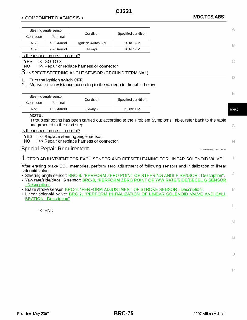
C1231[VDC/TCS/ABS]
C
D
E
G
H
I
J
K
L
M
A
B
RC
N
O
P
< COMPONENT DIAGNOSIS >
B
Is the inspection result normal?YES >> GO TO 3.NO >> Repair or replace harness or connector.
3.INSPECT STEERING ANGLE SENSOR (GROUND TERMINAL)
1. Turn the ignition switch OFF.2. Measure the resistance according to the value(s) in the table below.
NOTE:If troubleshooting has been carried out according to the Problem Symptoms Table, refer back to the tableand proceed to the next step.
Is the inspection result normal?YES >> Replace steering angle sensor.NO >> Repair or replace harness or connector.
Special Repair Requirement INFOID:0000000001501895
1.ZERO ADJUSTMENT FOR EACH SENSOR AND OFFSET LEANING FOR LINEAR SOLENOID VALVE
After erasing brake ECU memories, perform zero adjustment of following sensors and initialization of linearsolenoid valve.• Steering angle sensor: BRC-9, "PERFORM ZERO POINT OF STEERING ANGLE SENSOR : Description".• Yaw rate/side/decel G sensor: BRC-8, "PERFORM ZERO POINT OF YAW RATE/SIDE/DECEL G SENSOR
: Description".• Brake stroke sensor: BRC-9, "PERFORM ADJUSTMENT OF STROKE SENSOR : Description".• Linear solenoid valve: BRC-7, "PERFORM INITIALIZATION OF LINEAR SOLENOID VALVE AND CALI-
BRATION : Description".
>> END
Steering angle sensorCondition Specified condition
Connector Terminal
M53 4 – Ground Ignition switch ON 10 to 14 V
M53 7 – Ground Always 10 to 14 V
Steering angle sensorCondition Specified condition
Connector Terminal
M53 1 – Ground Always Below 1 Ω
BRC-75
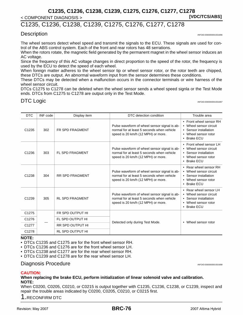
[VDC/TCS/ABS]C1235, C1236, C1238, C1239, C1275, C1276, C1277, C1278
< COMPONENT DIAGNOSIS >
C1235, C1236, C1238, C1239, C1275, C1276, C1277, C1278
Description INFOID:0000000001501896
The wheel sensors detect wheel speed and transmit the signals to the ECU. These signals are used for con-trol of the ABS control system. Each of the front and rear rotors has 48 serrations.When the rotors rotate, the magnetic field generated by the permanent magnet in the wheel sensor induces anAC voltage.Since the frequency of this AC voltage changes in direct proportion to the speed of the rotor, the frequency isused by the ECU to detect the speed of each wheel.When foreign matter adheres to the wheel sensor tip or wheel sensor rotor, or the rotor teeth are chipped,these DTCs are output. An abnormal waveform input from the sensor determines these conditions.These DTCs may be detected when a malfunction occurs in the connector terminals or wire harness of thewheel sensor circuit.DTCs C1275 to C1278 can be deleted when the wheel sensor sends a wheel speed signla or the Test Modeends. DTCs from C1275 to C1278 are output only in the Test Mode.
DTC Logic INFOID:0000000001501897
NOTE:• DTCs C1235 and C1275 are for the front wheel sensor RH.• DTCs C1236 and C1276 are for the front wheel sensor LH.• DTCs C1238 and C1277 are for the rear wheel sensor RH.• DTCs C1239 and C1278 are for the rear wheel sensor LH.
Diagnosis Procedure INFOID:0000000001501898
CAUTION:When replacing the brake ECU, perform initialization of linear solenoid valve and calibration.NOTE:When C0200, C0205, C0210, or C0215 is output together with C1235, C1236, C1238, or C1239, inspect andrepair the trouble areas indicated by C0200, C0205, C0210, or C0215 first.
1.RECONFIRM DTC
DTC INF code Display item DTC detection condition Trouble area
C1235 302 FR SPD FRAGMENTPulse waveform of wheel sensor signal is ab-normal for at least 5 seconds when vehicle speed is 20 km/h (12 MPH) or more.
• Front wheel sensor RH• Wheel sensor circuit• Sensor installation• Wheel sensor rotor• Brake ECU
C1236 303 FL SPD FRAGMENTPulse waveform of wheel sensor signal is ab-normal for at least 5 seconds when vehicle speed is 20 km/h (12 MPH) or more.
• Front wheel sensor LH• Wheel sensor circuit• Sensor installation• Wheel sensor rotor• Brake ECU
C1238 304 RR SPD FRAGMENTPulse waveform of wheel sensor signal is ab-normal for at least 5 seconds when vehicle speed is 20 km/h (12 MPH) or more.
• Rear wheel sensor RH• Wheel sensor circuit• Sensor installation• Wheel sensor rotor• Brake ECU
C1239 305 RL SPD FRAGMENTPulse waveform of wheel sensor signal is ab-normal for at least 5 seconds when vehicle speed is 20 km/h (12 MPH) or more.
• Rear wheel sensor LH• Wheel sensor circuit• Sensor installation• Wheel sensor rotor• Brake ECU
C1275
—
FR SPD OUTPUT HI
Detected only during Test Mode. • Wheel sensor rotorC1276 FL SPD OUTPUT HI
C1277 RR SPD OUTPUT HI
C1278 RL SPD OUTPUT HI
BRC-76

C1235, C1236, C1238, C1239, C1275, C1276, C1277, C1278[VDC/TCS/ABS]
C
D
E
G
H
I
J
K
L
M
A
B
RC
N
O
P
< COMPONENT DIAGNOSIS >
B
1. Turn the ignition switch OFF.2. Clear the DTC.3. Turn the ignition switch ON (READY).4. Drive the vehicle at the speed of 20 km/h (12 MPH) or more for at least 60 seconds.5. Check if the same DTC is recorded.
Result
A >> GO TO 2.B >> Replace brake ECU.
2.INSPECT EACH WHEEL SENSOR
1. Turn the ignition switch OFF.2. Disconnect each wheel sensor connector E41 (Front RH), E19 (Front LH), B43 (Rear).3. Measure the resistance according to the value(s) in the table below.
RH
LH
Result
Is the inspection result normal?A >> GO TO 3.B >> GO TO 4.C >> Replace each wheel sensor.
3.CHECK HARNESS AND CONNECTOR (BRAKE CONTROL SENSOR WIRE)
1. Disconnect the brake control sensor wire.2. Measure the resistance according to the value(s) in the table below.
Condition Proceed to
DTCs (C1235, C1236, C1238 and/or C1239) are not output. A
DTCs (C1235, C1236, C1238 and/or C1239) are output. B
Terminal Condition Specified condition
Front
1 – 2 Always Not existed
1 – Ground Always Existed
2 – Ground Always Existed
Rear
3 – 4 Always Not existed
3 – Ground Always Existed
4 – Ground Always Existed
Terminal Condition Specified condition
Front
1 – 2 Always Not existed
1 – Ground Always Existed
2 – Ground Always Existed
Rear
1 – 2 Always Not existed
1 – Ground Always Existed
2 – Ground Always Existed
Condition Proceed to
Yes (for rear) A
Yes (for front) B
No C
BRC-77
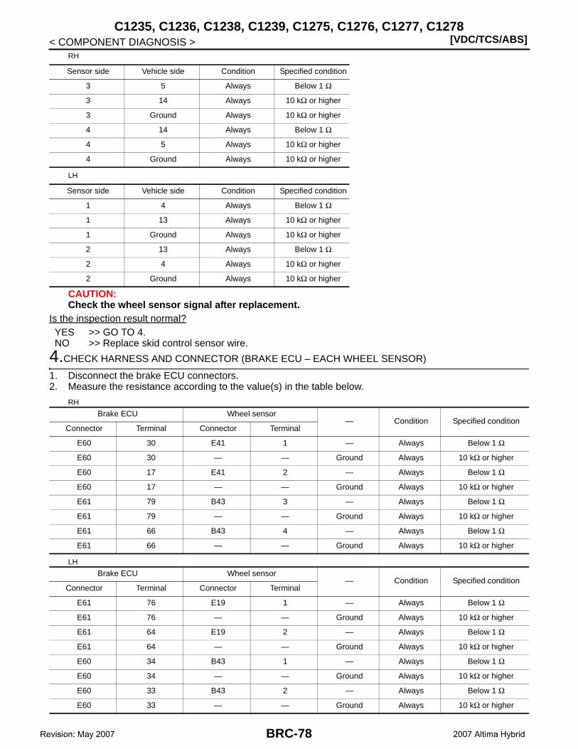
[VDC/TCS/ABS]C1235, C1236, C1238, C1239, C1275, C1276, C1277, C1278
< COMPONENT DIAGNOSIS >RH
LH
CAUTION:Check the wheel sensor signal after replacement.
Is the inspection result normal?YES >> GO TO 4.NO >> Replace skid control sensor wire.
4.CHECK HARNESS AND CONNECTOR (BRAKE ECU – EACH WHEEL SENSOR)
1. Disconnect the brake ECU connectors.2. Measure the resistance according to the value(s) in the table below.
RH
LH
Sensor side Vehicle side Condition Specified condition
3 5 Always Below 1 Ω
3 14 Always 10 kΩ or higher
3 Ground Always 10 kΩ or higher
4 14 Always Below 1 Ω
4 5 Always 10 kΩ or higher
4 Ground Always 10 kΩ or higher
Sensor side Vehicle side Condition Specified condition
1 4 Always Below 1 Ω
1 13 Always 10 kΩ or higher
1 Ground Always 10 kΩ or higher
2 13 Always Below 1 Ω
2 4 Always 10 kΩ or higher
2 Ground Always 10 kΩ or higher
Brake ECU Wheel sensor— Condition Specified condition
Connector Terminal Connector Terminal
E60 30 E41 1 — Always Below 1 Ω
E60 30 — — Ground Always 10 kΩ or higher
E60 17 E41 2 — Always Below 1 Ω
E60 17 — — Ground Always 10 kΩ or higher
E61 79 B43 3 — Always Below 1 Ω
E61 79 — — Ground Always 10 kΩ or higher
E61 66 B43 4 — Always Below 1 Ω
E61 66 — — Ground Always 10 kΩ or higher
Brake ECU Wheel sensor— Condition Specified condition
Connector Terminal Connector Terminal
E61 76 E19 1 — Always Below 1 Ω
E61 76 — — Ground Always 10 kΩ or higher
E61 64 E19 2 — Always Below 1 Ω
E61 64 — — Ground Always 10 kΩ or higher
E60 34 B43 1 — Always Below 1 Ω
E60 34 — — Ground Always 10 kΩ or higher
E60 33 B43 2 — Always Below 1 Ω
E60 33 — — Ground Always 10 kΩ or higher
BRC-78
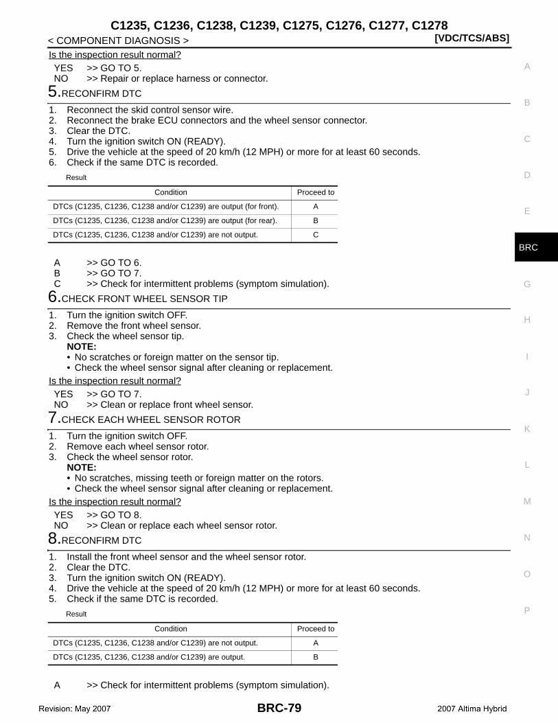
C1235, C1236, C1238, C1239, C1275, C1276, C1277, C1278[VDC/TCS/ABS]
C
D
E
G
H
I
J
K
L
M
A
B
RC
N
O
P
< COMPONENT DIAGNOSIS >
B
Is the inspection result normal?YES >> GO TO 5.NO >> Repair or replace harness or connector.
5.RECONFIRM DTC
1. Reconnect the skid control sensor wire.2. Reconnect the brake ECU connectors and the wheel sensor connector.3. Clear the DTC.4. Turn the ignition switch ON (READY).5. Drive the vehicle at the speed of 20 km/h (12 MPH) or more for at least 60 seconds.6. Check if the same DTC is recorded.
Result
A >> GO TO 6.B >> GO TO 7.C >> Check for intermittent problems (symptom simulation).
6.CHECK FRONT WHEEL SENSOR TIP
1. Turn the ignition switch OFF.2. Remove the front wheel sensor.3. Check the wheel sensor tip.
NOTE:• No scratches or foreign matter on the sensor tip.• Check the wheel sensor signal after cleaning or replacement.
Is the inspection result normal?YES >> GO TO 7.NO >> Clean or replace front wheel sensor.
7.CHECK EACH WHEEL SENSOR ROTOR
1. Turn the ignition switch OFF.2. Remove each wheel sensor rotor.3. Check the wheel sensor rotor.
NOTE:• No scratches, missing teeth or foreign matter on the rotors.• Check the wheel sensor signal after cleaning or replacement.
Is the inspection result normal?YES >> GO TO 8.NO >> Clean or replace each wheel sensor rotor.
8.RECONFIRM DTC
1. Install the front wheel sensor and the wheel sensor rotor.2. Clear the DTC.3. Turn the ignition switch ON (READY).4. Drive the vehicle at the speed of 20 km/h (12 MPH) or more for at least 60 seconds.5. Check if the same DTC is recorded.
Result
A >> Check for intermittent problems (symptom simulation).
Condition Proceed to
DTCs (C1235, C1236, C1238 and/or C1239) are output (for front). A
DTCs (C1235, C1236, C1238 and/or C1239) are output (for rear). B
DTCs (C1235, C1236, C1238 and/or C1239) are not output. C
Condition Proceed to
DTCs (C1235, C1236, C1238 and/or C1239) are not output. A
DTCs (C1235, C1236, C1238 and/or C1239) are output. B
BRC-79
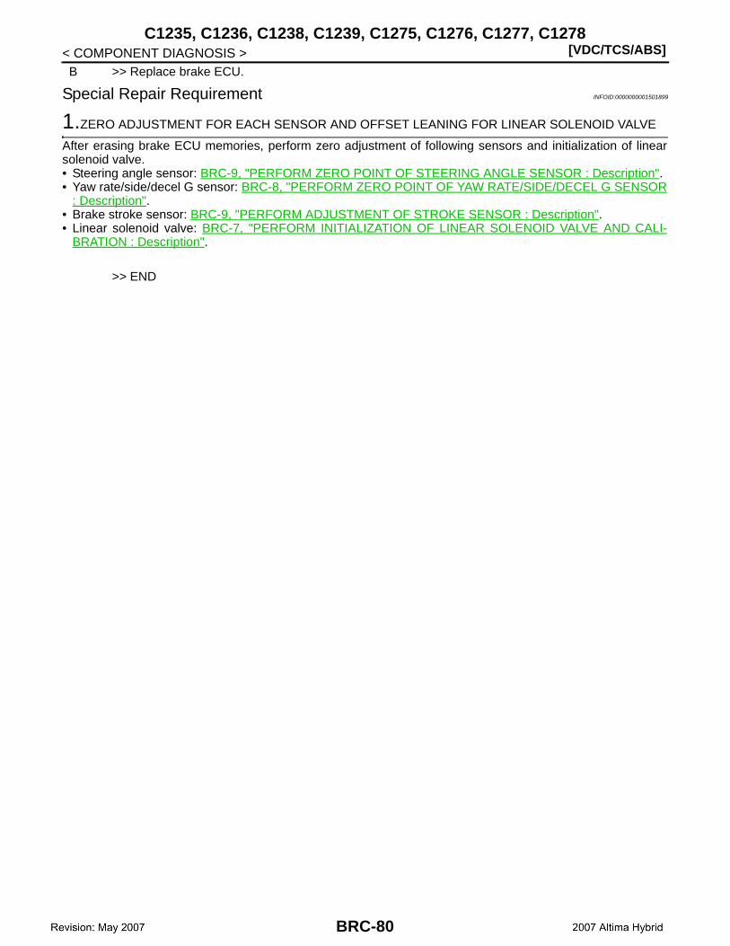
[VDC/TCS/ABS]C1235, C1236, C1238, C1239, C1275, C1276, C1277, C1278
< COMPONENT DIAGNOSIS >B >> Replace brake ECU.
Special Repair Requirement INFOID:0000000001501899
1.ZERO ADJUSTMENT FOR EACH SENSOR AND OFFSET LEANING FOR LINEAR SOLENOID VALVE
After erasing brake ECU memories, perform zero adjustment of following sensors and initialization of linearsolenoid valve.• Steering angle sensor: BRC-9, "PERFORM ZERO POINT OF STEERING ANGLE SENSOR : Description".• Yaw rate/side/decel G sensor: BRC-8, "PERFORM ZERO POINT OF YAW RATE/SIDE/DECEL G SENSOR
: Description".• Brake stroke sensor: BRC-9, "PERFORM ADJUSTMENT OF STROKE SENSOR : Description".• Linear solenoid valve: BRC-7, "PERFORM INITIALIZATION OF LINEAR SOLENOID VALVE AND CALI-
BRATION : Description".
>> END
BRC-80

C1241, C1242[VDC/TCS/ABS]
C
D
E
G
H
I
J
K
L
M
A
B
RC
N
O
P
< COMPONENT DIAGNOSIS >
B
C1241, C1242
Description INFOID:0000000001501900
These codes are memorized when the power source voltage for the brake ECU drops or the voltage for the ABS relay No.1 and ABS relay No.2 operation drops.Codes may be memorized when the voltage of the auxiliary battery temporarily drops.NOTE:DTC C1256 (ACCUMULATOR LOW PRESSURE malfunction) may be memorized if the power source voltagedrops.
DTC Logic INFOID:0000000001501901
DTC INF code Display item DTC detection condition Trouble area
C1241
81
POWER SUPPLY
System 1 is under the following conditions when the ignition switch is ON:• Linear solenoid cannot receive enough cur-
rent (brake is applied).• BS voltage is less than 8.9 V for at least 3
seconds (brake is not applied).• 12 V power source voltage inside ECU is
less than 8.5 V when main relay is opened or VCM voltage is less than 4.7 V or 5.3 V or more for at least 0.05 seconds.
• Auxiliary battery• ABS relay No.1• ABS relay No.1 circuit• Brake Capacitor• Hybrid control system
(Charging circuit)• Brake ECU
82
System 2 is under the following conditions when the ignition switch is ON:• Linear solenoid cannot receive enough cur-
rent (brake is applied).• BS voltage is less than 8.9 V for at least 3
seconds (brake is not applied).• 12 V power source voltage inside ECU is
less than 8.5 V when main relay is opened or VCM voltage is less than 4.7 V or 5.3 V or more for at least 0.05 seconds.
• Auxiliary battery• ABS relay No.2• ABS relay No.2 circuit• Brake capacitor• Hybrid control system
(Charging circuit)• Brake ECU
83Brake capacitor mode signal is received from brake control power supply for 3 seconds or more when the ignition switch is ON.
• Auxiliary battery• Brake capacitor• Hybrid control system
(Charging circuit)
91
In system 1, 12 V power source voltage inside brake ECU is less than 8.5 V when vehicle speed is 3 km/h (1.9 MPH) or more for at least 10 seconds.
• Auxiliary battery• Hybrid control system
(Charging circuit)• ABS relay No.1 circuit• Brake ECU
92
In system 2, 12 V power source voltage inside brake ECU is less than 8.5 V when vehicle speed is 3 km/h (1.9 MPH) or more for at least 10 seconds.
• Auxiliary battery• Hybrid control system
(Charging circuit)• ABS relay No.2 circuit• Brake ECU
93In system 1, 12 V power source voltage inside brake ECU is less than 8.5 V for at least 60 seconds.
• Auxiliary battery• Hybrid control system
(Charging circuit)• ABS relay No.1 circuit• Brake ECU
94In system 2, 12 V power source voltage inside brake ECU is less than 8.5 V for at least 60 seconds.
• Auxiliary battery• Hybrid control system
(Charging circuit)• ABS relay No.2 circuit• Brake ECU
BRC-81

[VDC/TCS/ABS]C1241, C1242
< COMPONENT DIAGNOSIS >
Diagnosis Procedure INFOID:0000000001501902
CAUTION:When replacing the brake ECU, perform initialization of linear solenoid valve and calibration.
1.CHECK HYBRID CONTROL SYSTEM
Check if the hybrid control system DTC is output.
Result
A >> GO TO 2.B >> Inspect hybrid control system.
2.CHECK AUXILIARY BATTERY
Check the auxiliary battery voltage.
Is the inspection result normal?YES >> GO TO 3.NO >> Charge or replace auxiliary battery.
3.INSPECT BRAKE ECU (IG AND +DI1 TERMINAL)
1. Disconnect the brake ECU connectors.2. Measure the voltage according to the value(s) in the table below.
Is the inspection result normal?YES >> GO TO 4.NO >> Repair or replace harness or connector (IG or +DI1 circuit).
4.INSPECT BRAKE ECU (GND TERMINAL)
1. Disconnect the brake ECU connectors.2. Measure the resistance according to the value(s) in the table below.
C1242
87
IG1/IG2
The power supply voltage is not applied to the IG1 terminal, power supply voltage is applied to the IG2 terminal, and DI1 terminal voltage is 9.5 V or more for 4 seconds or more.
• Auxiliary battery• IG1 power source cir-
cuit• Hybrid control system
(Charging circuit)• Brake ECU
88
The power supply voltage is applied to the IG1 terminal, power supply voltage is applied to the IG2 terminal, and DI1 terminal voltage is 9.5 V or more for 4 seconds or more.
• Auxiliary battery• IG2 power source cir-
cuit• Hybrid control system
(Charging circuit)• Brake ECU
DTC INF code Display item DTC detection condition Trouble area
Condition Proceed to
DTC is not output. A
DTC is output. B
Standard voltage : 11 to 14 V
Brake ECUCondition Specified condition
Connector Terminal
E60 29 – Ground Ignition switch ON 10 to 16 V
E61 75 – Ground Ignition switch ON 10 to 16 V
E60 16 – Ground Always 10 to 16 V
E60 8 – Ground Always 10 to 16 V
E61 58 – Ground Always 10 to 16 V
BRC-82
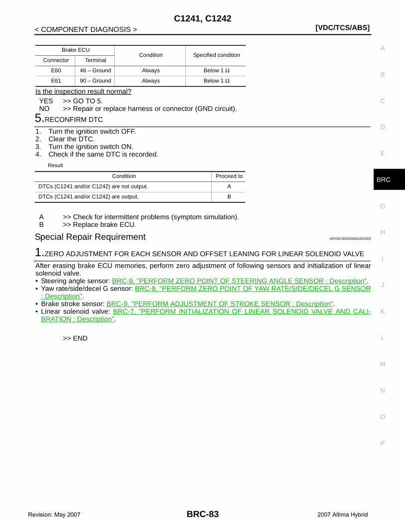
C1241, C1242[VDC/TCS/ABS]
C
D
E
G
H
I
J
K
L
M
A
B
RC
N
O
P
< COMPONENT DIAGNOSIS >
B
Is the inspection result normal?YES >> GO TO 5.NO >> Repair or replace harness or connector (GND circuit).
5.RECONFIRM DTC
1. Turn the ignition switch OFF.2. Clear the DTC.3. Turn the ignition switch ON.4. Check if the same DTC is recorded.
Result
A >> Check for intermittent problems (symptom simulation).B >> Replace brake ECU.
Special Repair Requirement INFOID:0000000001501903
1.ZERO ADJUSTMENT FOR EACH SENSOR AND OFFSET LEANING FOR LINEAR SOLENOID VALVE
After erasing brake ECU memories, perform zero adjustment of following sensors and initialization of linearsolenoid valve.• Steering angle sensor: BRC-9, "PERFORM ZERO POINT OF STEERING ANGLE SENSOR : Description".• Yaw rate/side/decel G sensor: BRC-8, "PERFORM ZERO POINT OF YAW RATE/SIDE/DECEL G SENSOR
: Description".• Brake stroke sensor: BRC-9, "PERFORM ADJUSTMENT OF STROKE SENSOR : Description".• Linear solenoid valve: BRC-7, "PERFORM INITIALIZATION OF LINEAR SOLENOID VALVE AND CALI-
BRATION : Description".
>> END
Brake ECUCondition Specified condition
Connector Terminal
E60 46 – Ground Always Below 1 Ω
E61 90 – Ground Always Below 1 Ω
Condition Proceed to
DTCs (C1241 and/or C1242) are not output. A
DTCs (C1241 and/or C1242) are output. B
BRC-83
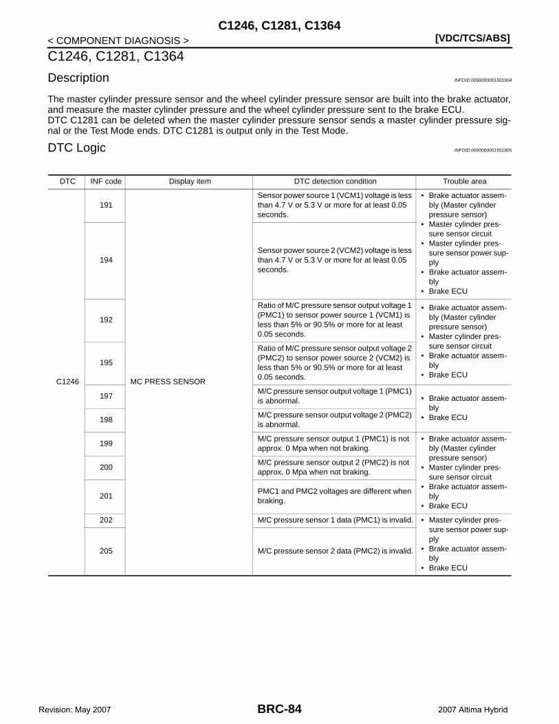
[VDC/TCS/ABS]C1246, C1281, C1364
< COMPONENT DIAGNOSIS >
C1246, C1281, C1364
Description INFOID:0000000001501904
The master cylinder pressure sensor and the wheel cylinder pressure sensor are built into the brake actuator,and measure the master cylinder pressure and the wheel cylinder pressure sent to the brake ECU.DTC C1281 can be deleted when the master cylinder pressure sensor sends a master cylinder pressure sig-nal or the Test Mode ends. DTC C1281 is output only in the Test Mode.
DTC Logic INFOID:0000000001501905
DTC INF code Display item DTC detection condition Trouble area
C1246
191
MC PRESS SENSOR
Sensor power source 1 (VCM1) voltage is less than 4.7 V or 5.3 V or more for at least 0.05 seconds.
• Brake actuator assem-bly (Master cylinder pressure sensor)
• Master cylinder pres-sure sensor circuit
• Master cylinder pres-sure sensor power sup-ply
• Brake actuator assem-bly
• Brake ECU
194Sensor power source 2 (VCM2) voltage is less than 4.7 V or 5.3 V or more for at least 0.05 seconds.
192
Ratio of M/C pressure sensor output voltage 1 (PMC1) to sensor power source 1 (VCM1) is less than 5% or 90.5% or more for at least 0.05 seconds.
• Brake actuator assem-bly (Master cylinder pressure sensor)
• Master cylinder pres-sure sensor circuit
• Brake actuator assem-bly
• Brake ECU
195
Ratio of M/C pressure sensor output voltage 2 (PMC2) to sensor power source 2 (VCM2) is less than 5% or 90.5% or more for at least 0.05 seconds.
197M/C pressure sensor output voltage 1 (PMC1) is abnormal. • Brake actuator assem-
bly• Brake ECU198
M/C pressure sensor output voltage 2 (PMC2) is abnormal.
199M/C pressure sensor output 1 (PMC1) is not approx. 0 Mpa when not braking.
• Brake actuator assem-bly (Master cylinder pressure sensor)
• Master cylinder pres-sure sensor circuit
• Brake actuator assem-bly
• Brake ECU
200M/C pressure sensor output 2 (PMC2) is not approx. 0 Mpa when not braking.
201PMC1 and PMC2 voltages are different when braking.
202 M/C pressure sensor 1 data (PMC1) is invalid. • Master cylinder pres-sure sensor power sup-ply
• Brake actuator assem-bly
• Brake ECU
205 M/C pressure sensor 2 data (PMC2) is invalid.
BRC-84

C1246, C1281, C1364[VDC/TCS/ABS]
C
D
E
G
H
I
J
K
L
M
A
B
RC
N
O
P
< COMPONENT DIAGNOSIS >
B
C1364
221
WC PRESS SEN
Sensor power source 1 (VCM1) voltage is less than 4.7 V or 5.3 V or more for at least 0.05 seconds.
• Wheel cylinder pres-sure sensor power sup-ply
• Brake actuator assem-bly
• Brake ECU227
Sensor power source 2 (VCM2) voltage is less than 4.7 V or 5.3 V or more for at least 0.05 seconds.
222
• Ratio of FR right sensor output voltage (PFR) to sensor power source 1 (VCM1) is less than 5% or 90.5% or more for at least 0.05 seconds.
• Open or short in FR right sensor (PFR) cir-cuit.
• Brake actuator assem-bly (wheel cylinder pressure sensor)
• Wheel cylinder pres-sure sensor
• Brake actuator assem-bly
• Brake ECU
224
When any of the following is detected:1. FR right sensor output (PFR) is not ap-
prox. 0 Mpa when not braking.2. FR right sensor (PFR) zero point mal-
function.
225
Ratio of FR right sensor output voltage (PFR) to sensor power source 1 (VCM1) is less than 90.5% for at least 0.1 second when self diag-nosis signal is output.
228
• Ratio of FR left sensor output voltage (PFL) to sensor power source 2 (VCM2) is less than 5% or 90.5% or more for at least 0.05 seconds.
• Open or short in FR left sensor (PFL) circuit.• Brake actuator assem-
bly (wheel cylinder pressure sensor)
• Wheel cylinder pres-sure sensor
• Brake actuator assem-bly
• Brake ECU
230
When any of the following is detected:1. FR left sensor output (PFL) is not ap-
prox. 0 Mpa when not braking.2. FR left sensor (PFL) zero point malfunc-
tion.
231
Ratio of FR left sensor output voltage (PFL) to sensor power source 2 (VCM2) is less than 90.5% for at least 0.1 second when self diag-nosis signal is output.
233Sensor power source 2 (VCM2) voltage is less than 4.7 V or 5.3 V or more for at least 0.05 seconds.
• Wheel cylinder pres-sure sensor power sup-ply
• Brake actuator assem-bly
• Brake ECU239
Sensor power source 1 (VCM1) voltage is less than 4.7 V or 5.3 V or more for at least 0.05 seconds.
234
• Ratio of RR right sensor output voltage (PRR) to sensor power source 2 (VCM2) is less than 5% or 90.5% or more for at least 0.05 seconds.
• Open or short in RR right sensor (PRR) sir-cuit.
• Brake actuator assem-bly (wheel cylinder pressure sensor)
• Wheel cylinder pres-sure sensor circuit
• Brake actuator assem-bly
• Brake ECU
236
When any of the following is detected:1. RR right sensor output (PRR) is not ap-
prox. 0 Mpa when not braking.2. RR right sensor (PRR) zero point mal-
function.
237
Ratio of RR right sensor output voltage (PRR) to sensor power source 2 (VCM2) is less than 90.5% for at least 0.1 second when self diag-nosis signal is output.
DTC INF code Display item DTC detection condition Trouble area
BRC-85

[VDC/TCS/ABS]C1246, C1281, C1364
< COMPONENT DIAGNOSIS >
Diagnosis Procedure INFOID:0000000001501906
CAUTION:When replacing the brake ECU or brake actuator assembly, perform initialization of linear solenoidvalve and calibration.
1.CHECK HARNESS AND CONNECTOR (BRAKE ECU – BRAKE ACTUATOR)
1. Disconnect the brake ECU connectors and the brake actuator connector.2. Measure the resistance according to the value(s) in the table below.
C1364
240
WC PRESS SEN
• Ratio of RR left sensor output voltage (PRL) to sensor power source 1 (VCM1) is less than 5% or 90.5% or more for at least 0.05 seconds.
• Open or short in RR left sensor (PRL) sir-cuit.
• Brake actuator assem-bly (wheel cylinder pressure sensor)
• Wheel cylinder pres-sure sensor circuit
• Brake actuator assem-bly
• Skid control ECU
242
When any of the following is detected:1. RR left sensor output (PRL) is not ap-
prox. 0 Mpa when not braking.2. RR left sensor (PRL) zero point malfunc-
tion.
243
Ratio of RR left sensor output voltage (PRL) to sensor power source 1 (VCM1) is less than 90.5% for at least 0.1 second when self diag-nosis signal is output.
C1281 — MC SENSOR OUTPUT Detected only during Test Mode.• Stop lamp switch• Master cylinder pres-
sure sensor
DTC INF code Display item DTC detection condition Trouble area
Brake ECU Brake actuator— Condition Specified condition
Connector Terminal Connector Terminal
E60 4 E91 14 — Always Below 1 Ω
E60 4 — — Ground Always 10 kΩ or higher
E60 18 E91 10 — Always Below 1 Ω
E60 18 — — Ground Always 10 kΩ or higher
E60 19 E91 15 — Always Below 1 Ω
E60 19 — — Ground Always 10 kΩ or higher
E60 3 E91 9 — Always Below 1 Ω
E60 3 — — Ground Always 10 kΩ or higher
E60 5 E91 11 — Always Below 1 Ω
E60 5 — — Ground Always 10 kΩ or higher
E60 31 E91 13 — Always Below 1 Ω
E60 31 — — Ground Always 10 kΩ or higher
E60 36 E91 12 — Always Below 1 Ω
E60 36 — — Ground Always 10 kΩ or higher
E61 65 E91 5 — Always Below 1 Ω
E61 65 — — Ground Always 10 kΩ or higher
E61 83 E91 7 — Always Below 1 Ω
E61 83 — — Ground Always 10 kΩ or higher
E61 52 E91 4 — Always Below 1 Ω
E61 52 — — Ground Always 10 kΩ or higher
E61 77 E91 8 — Always Below 1 Ω
BRC-86

C1246, C1281, C1364[VDC/TCS/ABS]
C
D
E
G
H
I
J
K
L
M
A
B
RC
N
O
P
< COMPONENT DIAGNOSIS >
B
Is the inspection result normal?YES >> GO TO 2.NO >> Repair or replace harness or connector.
2.READ VALUE OF CONSULT-III (MASTER CYLINDER PRESSURE SENSOR)
1. Reconnect the brake actuator connector.2. Connect the pedal effort gauge.3. Connect the CONSULT-III.4. Turn the ignition switch ON.5. Select the “DATA MONITOR” on the CONSULT-III.
ABS/VDC
6. Check the output value of the master cylinder pressure snesor at braking.NOTE:Output voltage must be proportional to the degree of pedal depression. There should not be a big differ-ence between outputs of sensor 1 and sensor 2.
Is the inspection result normal?YES >> GO TO 3.NO >> Replace brake actuator assembly.
3.READ VALUE OF CONSULT-III (WHEEL CYLINDER PRESSURE SENSOR)
1. Turn the ignition switch OFF.2. Turn the ignition switch ON.3. Select the “DATA MONITOR” on the CONSULT-III.
ABS/VDC
4. Check the output value of the wheel cylinder pressure sensor at each fluid pressure during the Electroni-cally Controlled Brake control.
Is the inspection result normal?
E61 77 — — Ground Always 10 kΩ or higher
E61 53 E91 16 — Always Below 1 Ω
E61 53 — — Ground Always 10 kΩ or higher
E61 54 E91 6 — Always Below 1 Ω
E61 54 — — Ground Always 10 kΩ or higher
Brake ECU Brake actuator— Condition Specified condition
Connector Terminal Connector Terminal
Tester display Measurement item/ Range Normal condition
MC SEN COMP 1Master cylinder pressure snesor 1 reading/ min: 0 V, max: 5 V
When brake pedal is re-leased: 0.3 to 0.9 V
MC SEN COMP 2Master cylinder pressure snesor 2 reading/ min: 0 V, max: 5 V
When brake pedal is re-leased: 0.3 to 0.9 V
Tester display Measurement item/ Range Normal condition
FR WC PRESS
FR wheel cylinder pressure sensor/ min: 0 V, max: 5 V
When brake pedal is re-leased: 0.3 to 0.9 V
FL WC PRESS
FL wheel cylinder pressure sensor/ min: 0 V, max: 5 V
When brake pedal is re-leased: 0.3 to 0.9 V
RR WC PRESS
RR wheel cylinder pressure sensor/ min: 0 V, max: 5 V
When brake pedal is re-leased: 0.3 to 0.9 V
RL WC PRESS
RL wheel cylinder pressure sensor/ min: 0 V, max: 5 V
When brake pedal is re-leased: 0.3 to 0.9 V
Condition Front wheel Rear wheel
When fully depressing the brake pedal with the vehicle stopped.
2.89 ±0.15 V 1.32 ±0.15 V
BRC-87
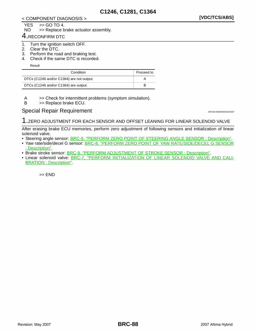
[VDC/TCS/ABS]C1246, C1281, C1364
< COMPONENT DIAGNOSIS >YES >> GO TO 4.NO >> Replace brake actuator assembly.
4.RECONFIRM DTC
1. Turn the ignition switch OFF.2. Clear the DTC.3. Perform the road and braking test.4. Check if the same DTC is recorded.
Result
A >> Check for intermittent problems (symptom simulation).B >> Replace brake ECU.
Special Repair Requirement INFOID:0000000001501907
1.ZERO ADJUSTMENT FOR EACH SENSOR AND OFFSET LEANING FOR LINEAR SOLENOID VALVE
After erasing brake ECU memories, perform zero adjustment of following sensors and initialization of linearsolenoid valve.• Steering angle sensor: BRC-9, "PERFORM ZERO POINT OF STEERING ANGLE SENSOR : Description".• Yaw rate/side/decel G sensor: BRC-8, "PERFORM ZERO POINT OF YAW RATE/SIDE/DECEL G SENSOR
: Description".• Brake stroke sensor: BRC-9, "PERFORM ADJUSTMENT OF STROKE SENSOR : Description".• Linear solenoid valve: BRC-7, "PERFORM INITIALIZATION OF LINEAR SOLENOID VALVE AND CALI-
BRATION : Description".
>> END
Condition Proceed to
DTCs (C1246 and/or C1364) are not output. A
DTCs (C1246 and/or C1364) are output. B
BRC-88
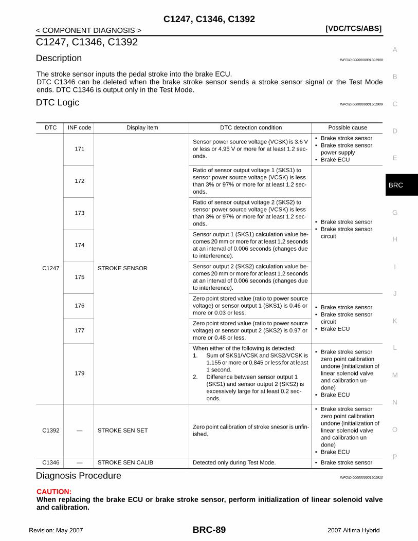
C1247, C1346, C1392[VDC/TCS/ABS]
C
D
E
G
H
I
J
K
L
M
A
B
RC
N
O
P
< COMPONENT DIAGNOSIS >
B
C1247, C1346, C1392
Description INFOID:0000000001501908
The stroke sensor inputs the pedal stroke into the brake ECU.DTC C1346 can be deleted when the brake stroke sensor sends a stroke sensor signal or the Test Modeends. DTC C1346 is output only in the Test Mode.
DTC Logic INFOID:0000000001501909
Diagnosis Procedure INFOID:0000000001501910
CAUTION:When replacing the brake ECU or brake stroke sensor, perform initialization of linear solenoid valveand calibration.
DTC INF code Display item DTC detection condition Possible cause
C1247
171
STROKE SENSOR
Sensor power source voltage (VCSK) is 3.6 V or less or 4.95 V or more for at least 1.2 sec-onds.
• Brake stroke sensor• Brake stroke sensor
power supply• Brake ECU
172
Ratio of sensor output voltage 1 (SKS1) to sensor power source voltage (VCSK) is less than 3% or 97% or more for at least 1.2 sec-onds.
• Brake stroke sensor• Brake stroke sensor
circuit
173
Ratio of sensor output voltage 2 (SKS2) to sensor power source voltage (VCSK) is less than 3% or 97% or more for at least 1.2 sec-onds.
174
Sensor output 1 (SKS1) calculation value be-comes 20 mm or more for at least 1.2 seconds at an interval of 0.006 seconds (changes due to interference).
175
Sensor output 2 (SKS2) calculation value be-comes 20 mm or more for at least 1.2 seconds at an interval of 0.006 seconds (changes due to interference).
176Zero point stored value (ratio to power source voltage) or sensor output 1 (SKS1) is 0.46 or more or 0.03 or less.
• Brake stroke sensor• Brake stroke sensor
circuit• Brake ECU177
Zero point stored value (ratio to power source voltage) or sensor output 2 (SKS2) is 0.97 or more or 0.48 or less.
179
When either of the following is detected:1. Sum of SKS1/VCSK and SKS2/VCSK is
1.155 or more or 0.845 or less for at least 1 second.
2. Difference between sensor output 1 (SKS1) and sensor output 2 (SKS2) is excessively large for at least 0.2 sec-onds.
• Brake stroke sensor zero point calibration undone (initialization of linear solenoid valve and calibration un-done)
• Brake ECU
C1392 — STROKE SEN SETZero point calibration of stroke snesor is unfin-ished.
• Brake stroke sensor zero point calibration undone (initialization of linear solenoid valve and calibration un-done)
• Brake ECU
C1346 — STROKE SEN CALIB Detected only during Test Mode. • Brake stroke sensor
BRC-89

[VDC/TCS/ABS]C1247, C1346, C1392
< COMPONENT DIAGNOSIS >
1.CHECK BRAKE PEDAL
1. Check that the brake pedal and the brake stroke sensor are properly installed and that the pedal can beoperated normally.
2. Check the brake pedal height.NOTE:• The brake pedal is securely installed.• The pedal height is within the specified range.
Is the inspection result normal?YES >> GO TO 2.NO >> Adjust brake pedal.
2.READ VALUE OF CONSULT-III (BRAKE STROKE SENSOR)
1. Connect the CONSULT-III.2. Turn the ignition switch ON.3. Select the “DATA MONITOR” on the CONSULT-III.
ABS/VDC:
4. Read the brake stroke sensor voltage value on the CONSULT-III screen.NOTE:The normal condition value is displayed on the CONSULT-III.
Is the inspection result normal?YES >> GO TO 3.NO >> Adjust brake stroke sensor.
3.PERFORM INITIALIZATION OF LINEAR SOLENOID VALVE AND CALIBRATION
Perform initialization of linear solenoid valve and calibration. Refer to BRC-7, "PERFORM INITIALIZATIONOF LINEAR SOLENOID VALVE AND CALIBRATION : Description".
>> GO TO 4.
4.RECONFIRM DTC
1. Turn the ignition switch OFF.2. Clear the DTC.3. Perform the road and braking test.4. Check if the same DTC is recorded.
Result
A >> GO TO 5.B >> INSPECTION END
5.CHECK HARNESS AND CONNECTOR (BRAKE ECU – BRAKE STROKE SENSOR)
1. Turn ignition switch OFF.2. Disconnect the brake ECU connector and the brake stroke sensor connector.3. Measure the resistance according to the value(s) in the table below.
Tester display Measurement item/ Range Normal condition
STRK COMP 1 Stroke sensor/ min: 0 V, max: 5 VWhen brake pedal is re-
leased: 0.7 to 1.3 V
STRK COMP 2 Stroke sensor 2/ min: 0 V, max: 5 VWhen brake pedal is re-
leased: 3.7 to 4.3 V
Condition Proceed to
DTCs (C1247 and/or C1392) are output. A
DTCs (C1247 and/or C1392) are not output. B
BRC-90
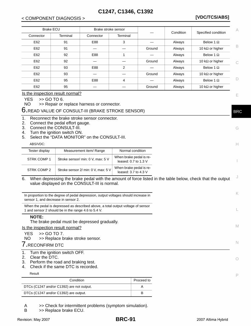
C1247, C1346, C1392[VDC/TCS/ABS]
C
D
E
G
H
I
J
K
L
M
A
B
RC
N
O
P
< COMPONENT DIAGNOSIS >
B
Is the inspection result normal?YES >> GO TO 6.NO >> Repair or replace harness or connector.
6.READ VALUE OF CONSULT-III (BRAKE STROKE SENSOR)
1. Reconnect the brake stroke sensor connector.2. Connect the pedal effort gauge.3. Connect the CONSULT-III.4. Turn the ignition switch ON.5. Select the “DATA MONITOR” on the CONSULT-III.
ABS/VDC:
6. When depressing the brake pedal with the amount of force listed in the table below, check that the outputvalue displayed on the CONSULT-III is normal.
NOTE:The brake pedal must be depressed gradually.
Is the inspection result normal?YES >> GO TO 7.NO >> Replace brake stroke sensor.
7.RECONFIRM DTC
1. Turn the ignition switch OFF.2. Clear the DTC.3. Perform the road and braking test.4. Check if the same DTC is recorded.
Result
A >> Check for intermittent problems (symptom simulation).B >> Replace brake ECU.
Brake ECU Brake stroke sensor— Condition Specified condition
Connector Terminal Connector Terminal
E62 91 E88 3 — Always Below 1 Ω
E62 91 — — Ground Always 10 kΩ or higher
E62 92 E88 1 — Always Below 1 Ω
E62 92 — — Ground Always 10 kΩ or higher
E62 93 E88 2 — Always Below 1 Ω
E62 93 — — Ground Always 10 kΩ or higher
E62 95 E88 4 — Always Below 1 Ω
E62 95 — — Ground Always 10 kΩ or higher
Tester display Measurement item/ Range Normal condition
STRK COMP 1 Stroke sensor/ min: 0 V, max: 5 VWhen brake pedal is re-
leased: 0.7 to 1.3 V
STRK COMP 2 Stroke sensor 2/ min: 0 V, max: 5 VWhen brake pedal is re-
leased: 3.7 to 4.3 V
In proportion to the degree of pedal depression, output voltages should increase in sensor 1, and decrease in sensor 2.
When the pedal is depressed as described above, a total output voltage of sensor 1 and sensor 2 should be in the range 4.6 to 5.4 V.
Condition Proceed to
DTCs (C1247 and/or C1392) are not output. A
DTCs (C1247 and/or C1392) are output. B
BRC-91
[VDC/TCS/ABS]C1247, C1346, C1392
< COMPONENT DIAGNOSIS >
Special Repair Requirement INFOID:0000000001501911
1.ZERO ADJUSTMENT FOR EACH SENSOR AND OFFSET LEANING FOR LINEAR SOLENOID VALVE
After erasing brake ECU memories, perform zero adjustment of following sensors and initialization of linearsolenoid valve.• Steering angle sensor: BRC-9, "PERFORM ZERO POINT OF STEERING ANGLE SENSOR : Description".• Yaw rate/side/decel G sensor: BRC-8, "PERFORM ZERO POINT OF YAW RATE/SIDE/DECEL G SENSOR
: Description".• Brake stroke sensor: BRC-9, "PERFORM ADJUSTMENT OF STROKE SENSOR : Description".• Linear solenoid valve: BRC-7, "PERFORM INITIALIZATION OF LINEAR SOLENOID VALVE AND CALI-
BRATION : Description".
>> END
BRC-92
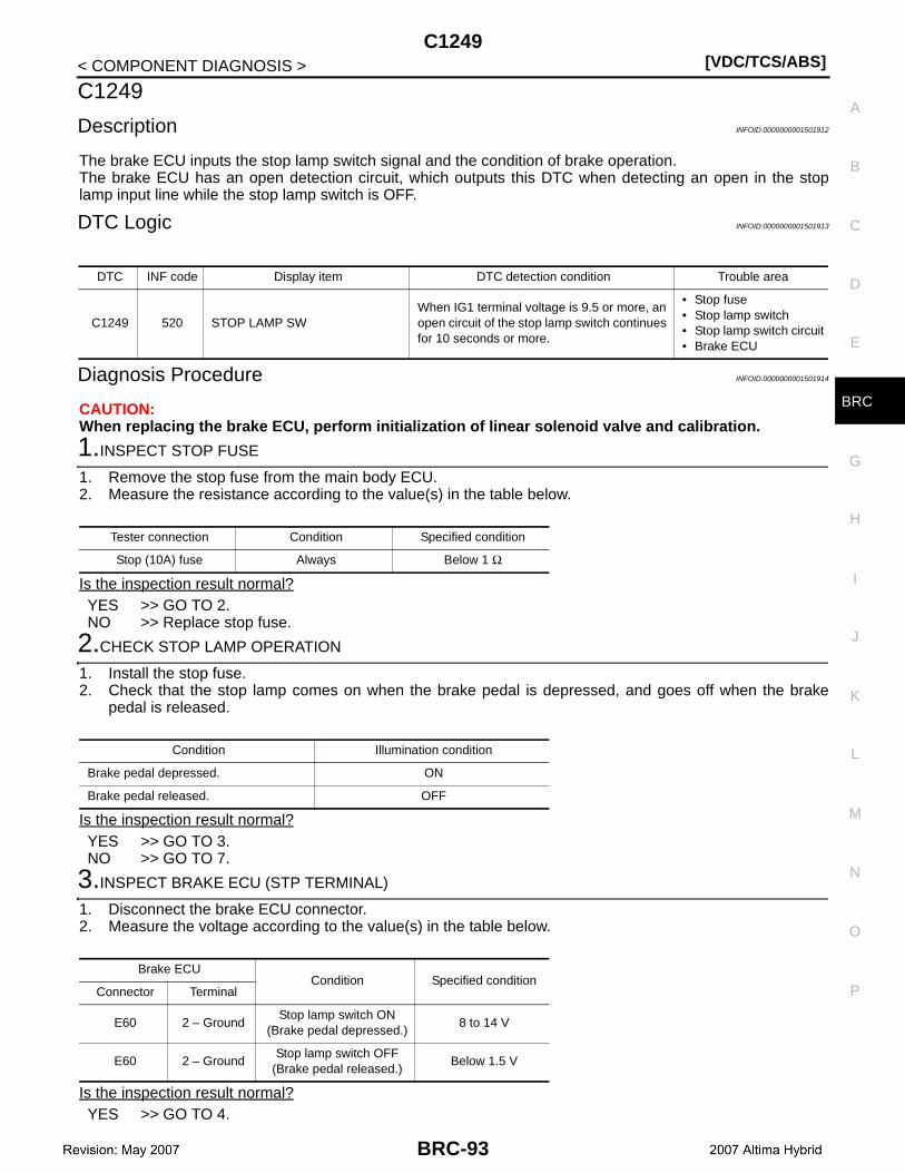
C1249[VDC/TCS/ABS]
C
D
E
G
H
I
J
K
L
M
A
B
RC
N
O
P
< COMPONENT DIAGNOSIS >
B
C1249
Description INFOID:0000000001501912
The brake ECU inputs the stop lamp switch signal and the condition of brake operation.The brake ECU has an open detection circuit, which outputs this DTC when detecting an open in the stoplamp input line while the stop lamp switch is OFF.
DTC Logic INFOID:0000000001501913
Diagnosis Procedure INFOID:0000000001501914
CAUTION:When replacing the brake ECU, perform initialization of linear solenoid valve and calibration.
1.INSPECT STOP FUSE
1. Remove the stop fuse from the main body ECU.2. Measure the resistance according to the value(s) in the table below.
Is the inspection result normal?YES >> GO TO 2.NO >> Replace stop fuse.
2.CHECK STOP LAMP OPERATION
1. Install the stop fuse.2. Check that the stop lamp comes on when the brake pedal is depressed, and goes off when the brake
pedal is released.
Is the inspection result normal?YES >> GO TO 3.NO >> GO TO 7.
3.INSPECT BRAKE ECU (STP TERMINAL)
1. Disconnect the brake ECU connector.2. Measure the voltage according to the value(s) in the table below.
Is the inspection result normal?YES >> GO TO 4.
DTC INF code Display item DTC detection condition Trouble area
C1249 520 STOP LAMP SWWhen IG1 terminal voltage is 9.5 or more, an open circuit of the stop lamp switch continues for 10 seconds or more.
• Stop fuse• Stop lamp switch• Stop lamp switch circuit• Brake ECU
Tester connection Condition Specified condition
Stop (10A) fuse Always Below 1 Ω
Condition Illumination condition
Brake pedal depressed. ON
Brake pedal released. OFF
Brake ECUCondition Specified condition
Connector Terminal
E60 2 – GroundStop lamp switch ON
(Brake pedal depressed.)8 to 14 V
E60 2 – GroundStop lamp switch OFF
(Brake pedal released.)Below 1.5 V
BRC-93
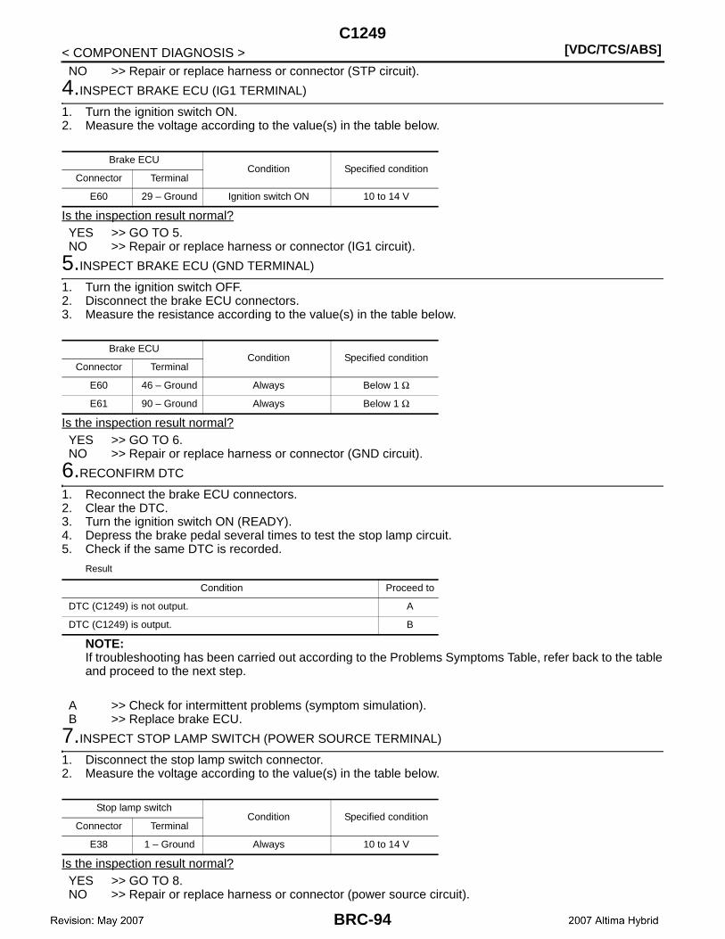
[VDC/TCS/ABS]C1249
< COMPONENT DIAGNOSIS >NO >> Repair or replace harness or connector (STP circuit).
4.INSPECT BRAKE ECU (IG1 TERMINAL)
1. Turn the ignition switch ON.2. Measure the voltage according to the value(s) in the table below.
Is the inspection result normal?YES >> GO TO 5.NO >> Repair or replace harness or connector (IG1 circuit).
5.INSPECT BRAKE ECU (GND TERMINAL)
1. Turn the ignition switch OFF.2. Disconnect the brake ECU connectors.3. Measure the resistance according to the value(s) in the table below.
Is the inspection result normal?YES >> GO TO 6.NO >> Repair or replace harness or connector (GND circuit).
6.RECONFIRM DTC
1. Reconnect the brake ECU connectors.2. Clear the DTC.3. Turn the ignition switch ON (READY).4. Depress the brake pedal several times to test the stop lamp circuit.5. Check if the same DTC is recorded.
Result
NOTE:If troubleshooting has been carried out according to the Problems Symptoms Table, refer back to the tableand proceed to the next step.
A >> Check for intermittent problems (symptom simulation).B >> Replace brake ECU.
7.INSPECT STOP LAMP SWITCH (POWER SOURCE TERMINAL)
1. Disconnect the stop lamp switch connector.2. Measure the voltage according to the value(s) in the table below.
Is the inspection result normal?YES >> GO TO 8.NO >> Repair or replace harness or connector (power source circuit).
Brake ECUCondition Specified condition
Connector Terminal
E60 29 – Ground Ignition switch ON 10 to 14 V
Brake ECUCondition Specified condition
Connector Terminal
E60 46 – Ground Always Below 1 Ω
E61 90 – Ground Always Below 1 Ω
Condition Proceed to
DTC (C1249) is not output. A
DTC (C1249) is output. B
Stop lamp switchCondition Specified condition
Connector Terminal
E38 1 – Ground Always 10 to 14 V
BRC-94
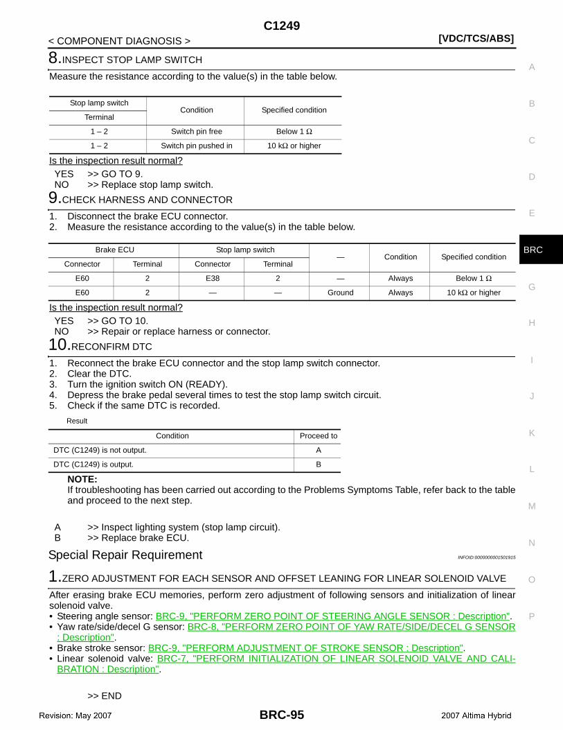
C1249[VDC/TCS/ABS]
C
D
E
G
H
I
J
K
L
M
A
B
RC
N
O
P
< COMPONENT DIAGNOSIS >
B
8.INSPECT STOP LAMP SWITCH
Measure the resistance according to the value(s) in the table below.
Is the inspection result normal?YES >> GO TO 9.NO >> Replace stop lamp switch.
9.CHECK HARNESS AND CONNECTOR
1. Disconnect the brake ECU connector.2. Measure the resistance according to the value(s) in the table below.
Is the inspection result normal?YES >> GO TO 10.NO >> Repair or replace harness or connector.
10.RECONFIRM DTC
1. Reconnect the brake ECU connector and the stop lamp switch connector.2. Clear the DTC.3. Turn the ignition switch ON (READY).4. Depress the brake pedal several times to test the stop lamp switch circuit.5. Check if the same DTC is recorded.
Result
NOTE:If troubleshooting has been carried out according to the Problems Symptoms Table, refer back to the tableand proceed to the next step.
A >> Inspect lighting system (stop lamp circuit).B >> Replace brake ECU.
Special Repair Requirement INFOID:0000000001501915
1.ZERO ADJUSTMENT FOR EACH SENSOR AND OFFSET LEANING FOR LINEAR SOLENOID VALVE
After erasing brake ECU memories, perform zero adjustment of following sensors and initialization of linearsolenoid valve.• Steering angle sensor: BRC-9, "PERFORM ZERO POINT OF STEERING ANGLE SENSOR : Description".• Yaw rate/side/decel G sensor: BRC-8, "PERFORM ZERO POINT OF YAW RATE/SIDE/DECEL G SENSOR
: Description".• Brake stroke sensor: BRC-9, "PERFORM ADJUSTMENT OF STROKE SENSOR : Description".• Linear solenoid valve: BRC-7, "PERFORM INITIALIZATION OF LINEAR SOLENOID VALVE AND CALI-
BRATION : Description".
>> END
Stop lamp switchCondition Specified condition
Terminal
1 – 2 Switch pin free Below 1 Ω
1 – 2 Switch pin pushed in 10 kΩ or higher
Brake ECU Stop lamp switch— Condition Specified condition
Connector Terminal Connector Terminal
E60 2 E38 2 — Always Below 1 Ω
E60 2 — — Ground Always 10 kΩ or higher
Condition Proceed to
DTC (C1249) is not output. A
DTC (C1249) is output. B
BRC-95
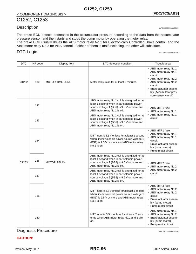
[VDC/TCS/ABS]C1252, C1253
< COMPONENT DIAGNOSIS >
C1252, C1253
Description INFOID:0000000001501916
The brake ECU detects decreases in the accumulator pressure according to the data from the accumulatorpressure sensor, and then starts and stops the pump motor by operating the motor relay.The brake ECU usually drives the ABS motor relay No.1 for Electronically Controlled Brake control, and theABS motor relay No.2 for ABS control. If either of them is malfunctioning, the other will substitute.
DTC Logic INFOID:0000000001501917
Diagnosis Procedure INFOID:0000000001501918
CAUTION:
DTC INF code Display item DTC detection condition Trouble area
C1252 130 MOTOR TIME LONG Motor relay is on for at least 5 minutes.
• ABS motor relay No.1• ABS motor relay No.1
circuit• ABS motor relay No.2• ABS motor relay No.2
circuit• Brake actuator assem-
bly (Accumulator pres-sure sensor circuit)
C1253
132
MOTOR RELAY
ABS motor relay No.1 coil is energized for at least 1 second when linear solenoid power source voltage 1 (BS1) is 9.5 V or more and ABS motor relay No.1 is off.
• ABS MTR1 fuse• ABS motor relay No.1• ABS motor relay No.1
circuit133
ABS motor relay No.1 coil is energized for at least 1 second when linear solenoid power source voltage 1 (BS1) is 9.5 V or more and ABS motor relay No.1 is on.
134
MTT input is 3.5 V or less for at least 1 second when linear solenoid power source voltage 1 (BS1) is 9.5 V or more and ABS motor relay No.1 is on.
• ABS MTR1 fuse• ABS motor relay No.1• ABS motor relay No.1
circuit• Brake actuator assem-
bly (pump motor)• Pump motor circuit
136
ABS motor relay No.2 coil is energized for at least 1 second when linear solenoid power source voltage 2 (BS2) is 9.5 V or more and ABS motor relay No.2 is off.
• ABS MTR2 fuse• ABS motor relay No.2• ABS motor relay No.2
circuit137
ABS motor relay No.2 coil is energized for at least 1 second when linear solenoid power source voltage 2 (BS2) is 9.5 V or more and ABS motor relay No.2 is on.
138
MTT input is 3.5 V or less for at least 1 second when linear solenoid power source voltage 1 (BS1) is 9.5 V or more and ABS motor relay No.2 is on.
• ABS MTR2 fuse• ABS motor relay No.2• ABS motor relay No.2
circuit• Brake actuator assem-
bly (pump motor)• Pump motor circuit
140MTT input is 3.5 V or less for at least 2 sec-onds when ABS motor relay No.1 and 2 are off.
• ABS motor relay No.1• ABS motor relay No.2• Brake actuator assem-
bly (pump motor)• Pump motor circuit
BRC-96

C1252, C1253[VDC/TCS/ABS]
C
D
E
G
H
I
J
K
L
M
A
B
RC
N
O
P
< COMPONENT DIAGNOSIS >
B
When replacing the brake ECU or brake actuator assembly, perform initialization of linear solenoidvalve and calibration.
1.INSPECT ABS MTR FUSE
1. Remove the fusible link from the engine room R/B.2. Check if the fusible link is melted.
NOTE:The fusible link is melted.
3. Install the fusible link to the engine room R/B with the bolt.Is the inspection result normal?YES >> GO TO 2.NO >> Replace fusible link (ABS MTR FUSE).
2.PERFORM ACTIVE TEST BY CONSULT-III (ABS MOTOR RELAY)
1. Connect the CONSULT-III.2. Turn the ignition switch ON.3. Select the “ACTIVE TEST” on the CONSULT-III.
4. Check the operation sound of the ABS motor relay and motor when operating it with the CONSULT-III.NOTE:The operation sound of the ABS motor relay and motor should be heard.
Is the inspection result normal?YES >> GO TO 3.NO >> GO TO 7.
3.INSPECT BRAKE ACTUATOR ASSEMBLY
1. Turn the ignition switch OFF.2. Disconnect the brake actuator connector.3. Measure the resistance according to the value(s) in the table below.
Is the inspection result normal?YES >> GO TO 4.NO >> Replace brake actuator assembly.
4.CHECK HARNESS AND CONNECTOR (BRAKE ECU – BRAKE ACTUATOR)
1. Disconnect the brake ECU connector.2. Measure the resistance according to the value(s) in the table below.
Display item Test part Control range Diagnostic note
MOTOR RELAY 1 ABS motor relay Relay ON/OFFOperate sound of relay (clicking sound) and motor can be heard.
MOTOR RELAY 2 ABS motor relay 2 Relay ON/OFFOperate sound of relay (clicking sound) and motor can be heard.
Brake actuatorCondition Specified condition
Connector Terminal
E91 32 – 2 Always Below 10 Ω
E91 31 – 2 Always Below 10 Ω
E91 31 – 32 Always Below 1 Ω
E91 1 – 2 Always Below 1 Ω
E91 32 – 3 Always 450 to 550 Ω
E91 31 – 3 Always 450 to 550 Ω
BRC-97
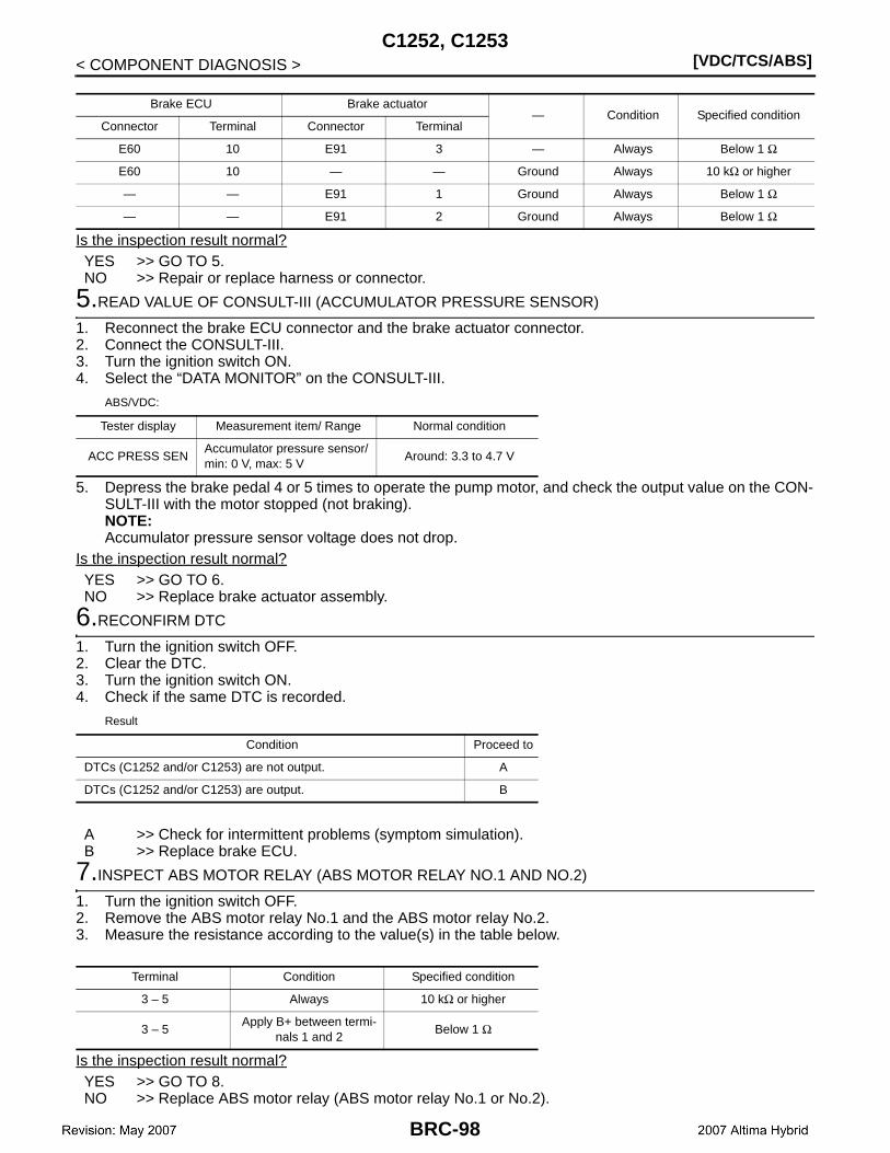
[VDC/TCS/ABS]C1252, C1253
< COMPONENT DIAGNOSIS >
Is the inspection result normal?YES >> GO TO 5.NO >> Repair or replace harness or connector.
5.READ VALUE OF CONSULT-III (ACCUMULATOR PRESSURE SENSOR)
1. Reconnect the brake ECU connector and the brake actuator connector.2. Connect the CONSULT-III.3. Turn the ignition switch ON.4. Select the “DATA MONITOR” on the CONSULT-III.
ABS/VDC:
5. Depress the brake pedal 4 or 5 times to operate the pump motor, and check the output value on the CON-SULT-III with the motor stopped (not braking).NOTE:Accumulator pressure sensor voltage does not drop.
Is the inspection result normal?YES >> GO TO 6.NO >> Replace brake actuator assembly.
6.RECONFIRM DTC
1. Turn the ignition switch OFF.2. Clear the DTC.3. Turn the ignition switch ON.4. Check if the same DTC is recorded.
Result
A >> Check for intermittent problems (symptom simulation).B >> Replace brake ECU.
7.INSPECT ABS MOTOR RELAY (ABS MOTOR RELAY NO.1 AND NO.2)
1. Turn the ignition switch OFF.2. Remove the ABS motor relay No.1 and the ABS motor relay No.2.3. Measure the resistance according to the value(s) in the table below.
Is the inspection result normal?YES >> GO TO 8.NO >> Replace ABS motor relay (ABS motor relay No.1 or No.2).
Brake ECU Brake actuator— Condition Specified condition
Connector Terminal Connector Terminal
E60 10 E91 3 — Always Below 1 Ω
E60 10 — — Ground Always 10 kΩ or higher
— — E91 1 Ground Always Below 1 Ω
— — E91 2 Ground Always Below 1 Ω
Tester display Measurement item/ Range Normal condition
ACC PRESS SENAccumulator pressure sensor/ min: 0 V, max: 5 V
Around: 3.3 to 4.7 V
Condition Proceed to
DTCs (C1252 and/or C1253) are not output. A
DTCs (C1252 and/or C1253) are output. B
Terminal Condition Specified condition
3 – 5 Always 10 kΩ or higher
3 – 5Apply B+ between termi-
nals 1 and 2Below 1 Ω
BRC-98
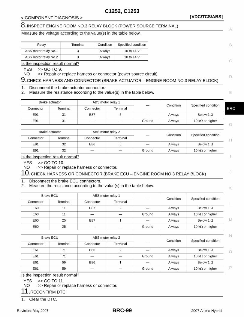
C1252, C1253[VDC/TCS/ABS]
C
D
E
G
H
I
J
K
L
M
A
B
RC
N
O
P
< COMPONENT DIAGNOSIS >
B
8.INSPECT ENGINE ROOM NO.3 RELAY BLOCK (POWER SOURCE TERMINAL)
Measure the voltage according to the value(s) in the table below.
Is the inspection result normal?YES >> GO TO 9.NO >> Repair or replace harness or connector (power source circuit).
9.CHECK HARNESS AND CONNECTOR (BRAKE ACTUATOR – ENGINE ROOM NO.3 RELAY BLOCK)
1. Disconnect the brake actuator connector.2. Measure the resistance according to the value(s) in the table below.
Is the inspection result normal?YES >> GO TO 10.NO >> Repair or replace harness or connector.
10.CHECK HARNESS OR CONNECTOR (BRAKE ECU – ENGINE ROOM NO.3 RELAY BLOCK)
1. Disconnect the brake ECU connectors.2. Measure the resistance according to the value(s) in the table below.
Is the inspection result normal?YES >> GO TO 11.NO >> Repair or replace harness or connector.
11.RECONFIRM DTC
1. Clear the DTC.
Relay Terminal Condition Specified condition
ABS motor relay No.1 3 Always 10 to 14 V
ABS motor relay No.2 3 Always 10 to 14 V
Brake actuator ABS motor relay 1— Condition Specified condition
Connector Terminal Connector Terminal
E91 31 E87 5 — Always Below 1 Ω
E91 31 — — Ground Always 10 kΩ or higher
Brake actuator ABS motor relay 2— Condition Specified condition
Connector Terminal Connector Terminal
E91 32 E86 5 — Always Below 1 Ω
E91 32 — — Ground Always 10 kΩ or higher
Brake ECU ABS motor relay 1— Condition Specified condition
Connector Terminal Connector Terminal
E60 11 E87 2 — Always Below 1 Ω
E60 11 — — Ground Always 10 kΩ or higher
E60 25 E87 1 — Always Below 1 Ω
E60 25 — — Ground Always 10 kΩ or higher
Brake ECU ABS motor relay 2— Condition Specified condition
Connector Terminal Connector Terminal
E61 71 E86 2 — Always Below 1 Ω
E61 71 — — Ground Always 10 kΩ or higher
E61 59 E86 1 — Always Below 1 Ω
E61 59 — — Ground Always 10 kΩ or higher
BRC-99

[VDC/TCS/ABS]C1252, C1253
< COMPONENT DIAGNOSIS >2. Turn the ignition switch ON.3. Check if the same DTC is recorded.
NOTE:Reinstall the relays, connectors, etc. and restore the vehicle to its prior condition before rechecking forDTCs.
Result
A >> Check for intermittent problems (symptom simulation).B >> Replace brake ECU.
Special Repair Requirement INFOID:0000000001501919
1.ZERO ADJUSTMENT FOR EACH SENSOR AND OFFSET LEANING FOR LINEAR SOLENOID VALVE
After erasing brake ECU memories, perform zero adjustment of following sensors and initialization of linearsolenoid valve.• Steering angle sensor: BRC-9, "PERFORM ZERO POINT OF STEERING ANGLE SENSOR : Description".• Yaw rate/side/decel G sensor: BRC-8, "PERFORM ZERO POINT OF YAW RATE/SIDE/DECEL G SENSOR
: Description".• Brake stroke sensor: BRC-9, "PERFORM ADJUSTMENT OF STROKE SENSOR : Description".• Linear solenoid valve: BRC-7, "PERFORM INITIALIZATION OF LINEAR SOLENOID VALVE AND CALI-
BRATION : Description".
>> END
Condition Proceed to
DTCs (C1252 and/or C1253) are not output. A
DTCs (C1252 and/or C1253) are output. B
BRC-100
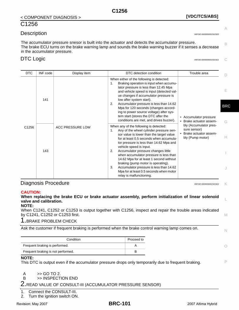
C1256[VDC/TCS/ABS]
C
D
E
G
H
I
J
K
L
M
A
B
RC
N
O
P
< COMPONENT DIAGNOSIS >
B
C1256
Description INFOID:0000000001501920
The accumulator pressure snesor is built into the actuator and detects the accumulator pressure.The brake ECU turns on the brake warning lamp and sounds the brake warning buzzer if it senses a decreasein the accumulator pressure.
DTC Logic INFOID:0000000001501921
Diagnosis Procedure INFOID:0000000001501922
CAUTION:When replacing the brake ECU or brake actuator assembly, perform initialization of linear solenoidvalve and calibration.NOTE:When C1241, C1252 or C1253 is output together with C1256, inspect and repair the trouble areas indicatedby C1241, C1252 or C1253 first.
1.BRAKE PROBLEM CHECK
Ask the customer if frequent braking is performed when the brake control warning lamp comes on.
NOTE:This DTC is output even if the accumulator pressure drops only temporarily due to frequent braking.
A >> GO TO 2.B >> INSPECTION END
2.READ VALUE OF CONSULT-III (ACCUMULATOR PRESSURE SENSOR)
1. Connect the CONSULT-III.2. Turn the ignition switch ON.
DTC INF code Display item DTC detection condition Trouble area
C1256
141
ACC PRESSURE LOW
When either of the following is detected:1. Braking operation is input when accumu-
lator pressure is less than 12.45 Mpa and vehicle speed is input (detected val-ue changes if accumulator pressure is low after system start).
2. Accumulator pressure is less than 14.62 Mpa for 120 seconds (changes accord-ing to power source voltage) after sys-tem start (stores the DTC after the conditions are met, and drives buzzer).
• Accumulator pressure• Brake actuator assem-
bly (Accumulator pres-sure sensor)
• Brake actuator assem-bly (Pump motor)
143
When any of the following is detected:1. Any of the wheel cylinder pressure sen-
sor value is lower than the target value for at least 0.5 seconds when accumula-tor pressure is less than 14.62 Mpa and vehicle speed is input.
2. Accumulator pressure changes little when accumulator pressure is less than 14.62 Mpa for at least 1 second without braking (pump motor is operating).
3. Accumulator pressure is less than 14.62 Mpa for at least 0.5 seconds when motor relay is malfunctioning.
Condition Proceed to
Frequent braking is performed. A
Frequent braking is not performed. B
BRC-101
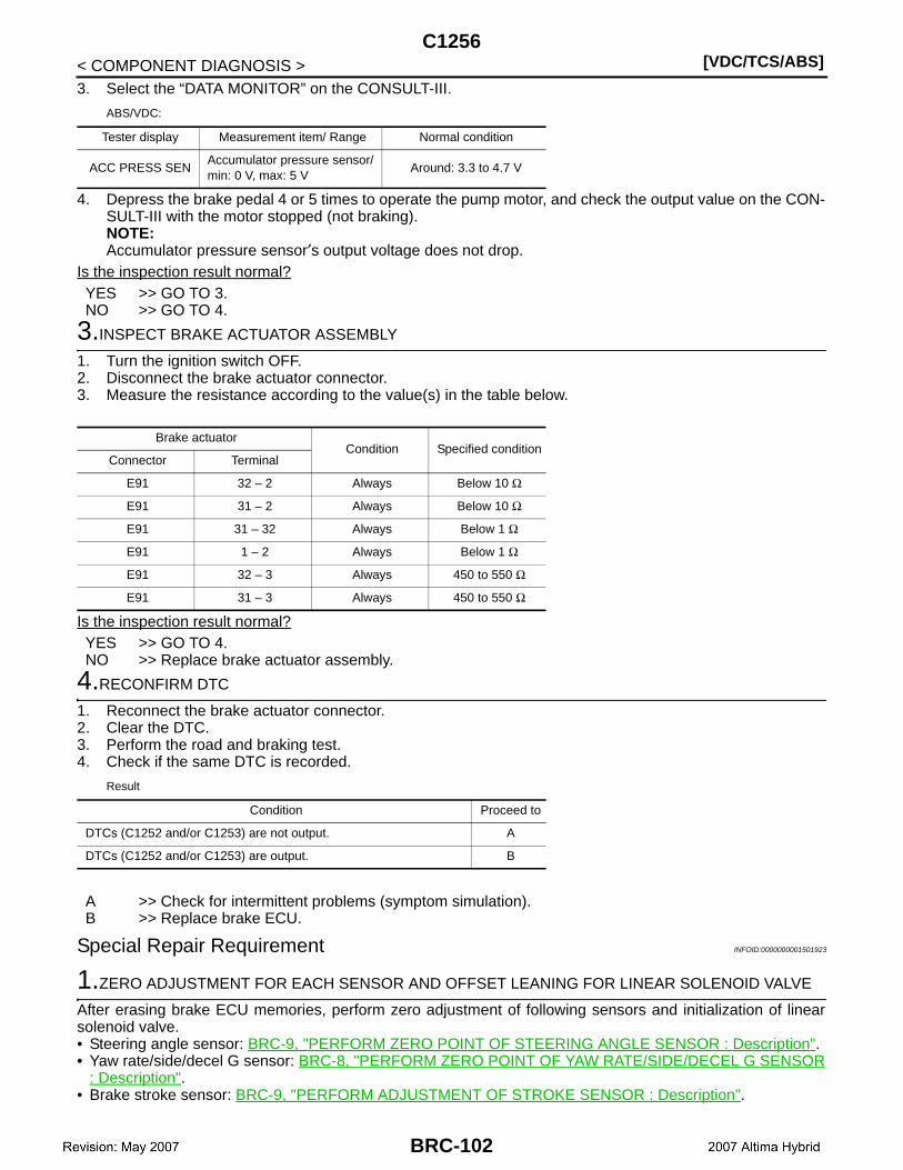
[VDC/TCS/ABS]C1256
< COMPONENT DIAGNOSIS >3. Select the “DATA MONITOR” on the CONSULT-III.
ABS/VDC:
4. Depress the brake pedal 4 or 5 times to operate the pump motor, and check the output value on the CON-SULT-III with the motor stopped (not braking).NOTE:Accumulator pressure sensor′s output voltage does not drop.
Is the inspection result normal?YES >> GO TO 3.NO >> GO TO 4.
3.INSPECT BRAKE ACTUATOR ASSEMBLY
1. Turn the ignition switch OFF.2. Disconnect the brake actuator connector.3. Measure the resistance according to the value(s) in the table below.
Is the inspection result normal?YES >> GO TO 4.NO >> Replace brake actuator assembly.
4.RECONFIRM DTC
1. Reconnect the brake actuator connector.2. Clear the DTC.3. Perform the road and braking test.4. Check if the same DTC is recorded.
Result
A >> Check for intermittent problems (symptom simulation).B >> Replace brake ECU.
Special Repair Requirement INFOID:0000000001501923
1.ZERO ADJUSTMENT FOR EACH SENSOR AND OFFSET LEANING FOR LINEAR SOLENOID VALVE
After erasing brake ECU memories, perform zero adjustment of following sensors and initialization of linearsolenoid valve.• Steering angle sensor: BRC-9, "PERFORM ZERO POINT OF STEERING ANGLE SENSOR : Description".• Yaw rate/side/decel G sensor: BRC-8, "PERFORM ZERO POINT OF YAW RATE/SIDE/DECEL G SENSOR
: Description".• Brake stroke sensor: BRC-9, "PERFORM ADJUSTMENT OF STROKE SENSOR : Description".
Tester display Measurement item/ Range Normal condition
ACC PRESS SENAccumulator pressure sensor/ min: 0 V, max: 5 V
Around: 3.3 to 4.7 V
Brake actuatorCondition Specified condition
Connector Terminal
E91 32 – 2 Always Below 10 Ω
E91 31 – 2 Always Below 10 Ω
E91 31 – 32 Always Below 1 Ω
E91 1 – 2 Always Below 1 Ω
E91 32 – 3 Always 450 to 550 Ω
E91 31 – 3 Always 450 to 550 Ω
Condition Proceed to
DTCs (C1252 and/or C1253) are not output. A
DTCs (C1252 and/or C1253) are output. B
BRC-102
C1256[VDC/TCS/ABS]
C
D
E
G
H
I
J
K
L
M
A
B
RC
N
O
P
< COMPONENT DIAGNOSIS >
B
• Linear solenoid valve: BRC-7, "PERFORM INITIALIZATION OF LINEAR SOLENOID VALVE AND CALI-BRATION : Description".
>> END
BRC-103
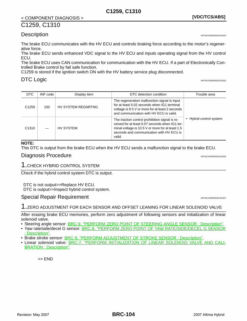
[VDC/TCS/ABS]C1259, C1310
< COMPONENT DIAGNOSIS >
C1259, C1310
Description INFOID:0000000001501924
The brake ECU communicates with the HV ECU and controls braking force according to the motor′s regener-ative force.The brake ECU sends enhanced VDC signal to the HV ECU and inputs operating signal from the HV controlECU.The brake ECU uses CAN communication for communication with the HV ECU. If a part of Electronically Con-trolled Brake control by fail safe function.C1259 is stored if the ignition switch ON with the HV battery service plug disconnected.
DTC Logic INFOID:0000000001501925
NOTE:This DTC is output from the brake ECU when the HV ECU sends a malfunction signal to the brake ECU.
Diagnosis Procedure INFOID:0000000001501926
1.CHECK HYBRID CONTROL SYSTEM
Check if the hybrid control system DTC is output.
DTC is not output>>Replace HV ECU.DTC is output>>Inspect hybrid control system.
Special Repair Requirement INFOID:0000000001501927
1.ZERO ADJUSTMENT FOR EACH SENSOR AND OFFSET LEANING FOR LINEAR SOLENOID VALVE
After erasing brake ECU memories, perform zero adjustment of following sensors and initialization of linearsolenoid valve.• Steering angle sensor: BRC-9, "PERFORM ZERO POINT OF STEERING ANGLE SENSOR : Description".• Yaw rate/side/decel G sensor: BRC-8, "PERFORM ZERO POINT OF YAW RATE/SIDE/DECEL G SENSOR
: Description".• Brake stroke sensor: BRC-9, "PERFORM ADJUSTMENT OF STROKE SENSOR : Description".• Linear solenoid valve: BRC-7, "PERFORM INITIALIZATION OF LINEAR SOLENOID VALVE AND CALI-
BRATION : Description".
>> END
DTC INF code Display item DTC detection condition Trouble area
C1259 150 HV SYSTEM REGNRTNG
The regeneration malfunction signal is input for at least 0.02 seconds when IG1 terminal voltage is 9.5 V or more for at least 2 seconds and communication with HV ECU is valid.
• Hybrid control system
C1310 — HV SYSTEM
The traction control prohibition signal is re-ceived for at least 0.07 seconds when IG1 ter-minal voltage is 10.5 V or more for at least 1.5 seconds and communication with HV ECU is valid.
BRC-104
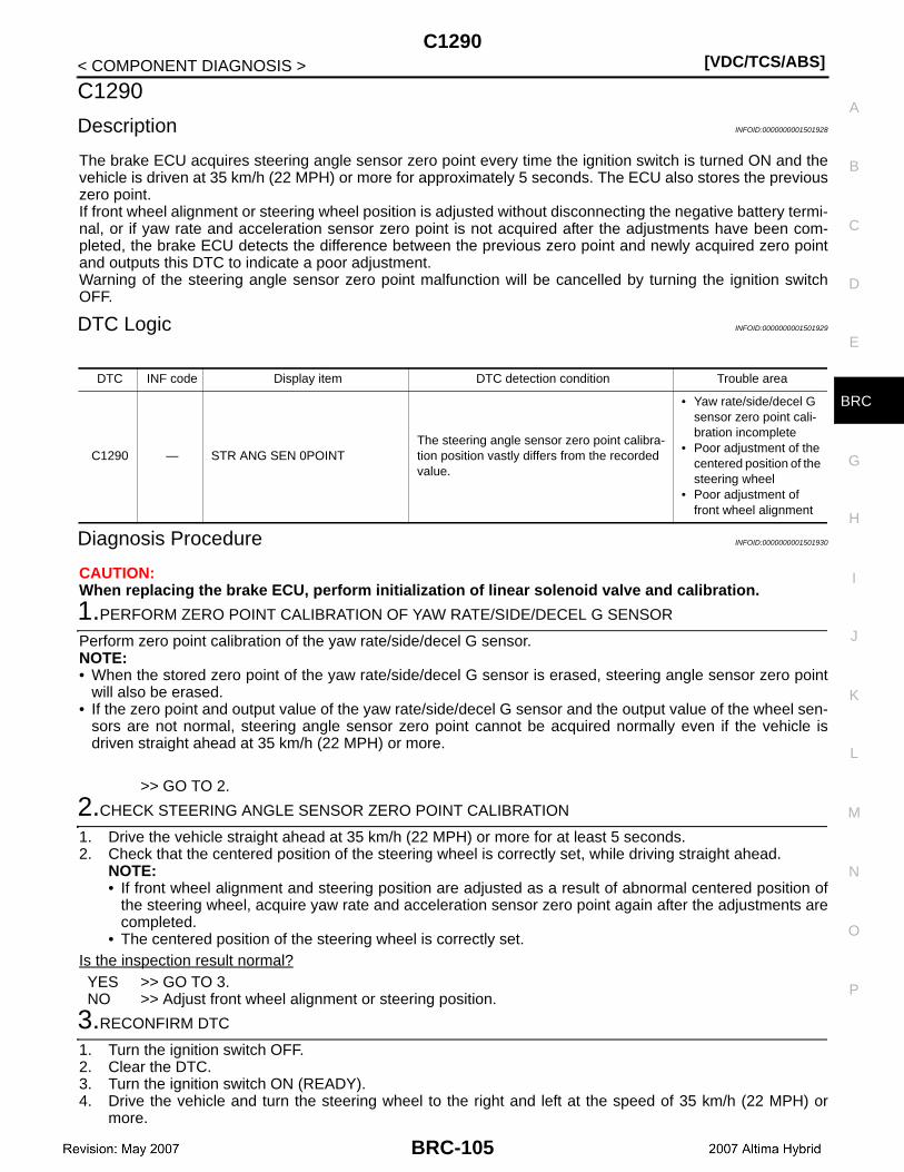
C1290[VDC/TCS/ABS]
C
D
E
G
H
I
J
K
L
M
A
B
RC
N
O
P
< COMPONENT DIAGNOSIS >
B
C1290
Description INFOID:0000000001501928
The brake ECU acquires steering angle sensor zero point every time the ignition switch is turned ON and thevehicle is driven at 35 km/h (22 MPH) or more for approximately 5 seconds. The ECU also stores the previouszero point.If front wheel alignment or steering wheel position is adjusted without disconnecting the negative battery termi-nal, or if yaw rate and acceleration sensor zero point is not acquired after the adjustments have been com-pleted, the brake ECU detects the difference between the previous zero point and newly acquired zero pointand outputs this DTC to indicate a poor adjustment.Warning of the steering angle sensor zero point malfunction will be cancelled by turning the ignition switchOFF.
DTC Logic INFOID:0000000001501929
Diagnosis Procedure INFOID:0000000001501930
CAUTION:When replacing the brake ECU, perform initialization of linear solenoid valve and calibration.
1.PERFORM ZERO POINT CALIBRATION OF YAW RATE/SIDE/DECEL G SENSOR
Perform zero point calibration of the yaw rate/side/decel G sensor.NOTE:• When the stored zero point of the yaw rate/side/decel G sensor is erased, steering angle sensor zero point
will also be erased.• If the zero point and output value of the yaw rate/side/decel G sensor and the output value of the wheel sen-
sors are not normal, steering angle sensor zero point cannot be acquired normally even if the vehicle isdriven straight ahead at 35 km/h (22 MPH) or more.
>> GO TO 2.
2.CHECK STEERING ANGLE SENSOR ZERO POINT CALIBRATION
1. Drive the vehicle straight ahead at 35 km/h (22 MPH) or more for at least 5 seconds.2. Check that the centered position of the steering wheel is correctly set, while driving straight ahead.
NOTE:• If front wheel alignment and steering position are adjusted as a result of abnormal centered position of
the steering wheel, acquire yaw rate and acceleration sensor zero point again after the adjustments arecompleted.
• The centered position of the steering wheel is correctly set.Is the inspection result normal?YES >> GO TO 3.NO >> Adjust front wheel alignment or steering position.
3.RECONFIRM DTC
1. Turn the ignition switch OFF.2. Clear the DTC.3. Turn the ignition switch ON (READY).4. Drive the vehicle and turn the steering wheel to the right and left at the speed of 35 km/h (22 MPH) or
more.
DTC INF code Display item DTC detection condition Trouble area
C1290 — STR ANG SEN 0POINTThe steering angle sensor zero point calibra-tion position vastly differs from the recorded value.
• Yaw rate/side/decel G sensor zero point cali-bration incomplete
• Poor adjustment of the centered position of the steering wheel
• Poor adjustment of front wheel alignment
BRC-105
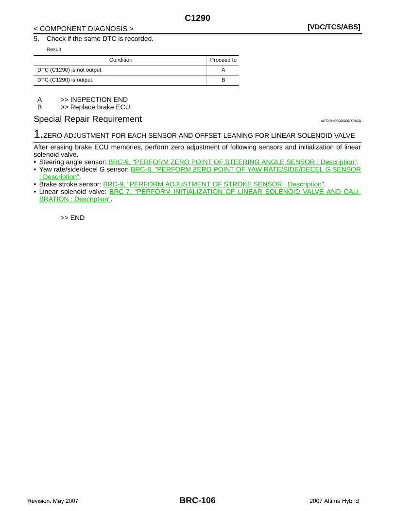
[VDC/TCS/ABS]C1290
< COMPONENT DIAGNOSIS >5. Check if the same DTC is recorded.
Result
A >> INSPECTION ENDB >> Replace brake ECU.
Special Repair Requirement INFOID:0000000001501931
1.ZERO ADJUSTMENT FOR EACH SENSOR AND OFFSET LEANING FOR LINEAR SOLENOID VALVE
After erasing brake ECU memories, perform zero adjustment of following sensors and initialization of linearsolenoid valve.• Steering angle sensor: BRC-9, "PERFORM ZERO POINT OF STEERING ANGLE SENSOR : Description".• Yaw rate/side/decel G sensor: BRC-8, "PERFORM ZERO POINT OF YAW RATE/SIDE/DECEL G SENSOR
: Description".• Brake stroke sensor: BRC-9, "PERFORM ADJUSTMENT OF STROKE SENSOR : Description".• Linear solenoid valve: BRC-7, "PERFORM INITIALIZATION OF LINEAR SOLENOID VALVE AND CALI-
BRATION : Description".
>> END
Condition Proceed to
DTC (C1290) is not output. A
DTC (C1290) is output. B
BRC-106
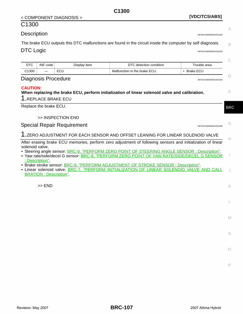
C1300[VDC/TCS/ABS]
C
D
E
G
H
I
J
K
L
M
A
B
RC
N
O
P
< COMPONENT DIAGNOSIS >
B
C1300
Description INFOID:0000000001501932
The brake ECU outputs this DTC malfunctions are found in the circuit inside the computer by self diagnosis.
DTC Logic INFOID:0000000001501933
Diagnosis Procedure INFOID:0000000001501934
CAUTION:When replacing the brake ECU, perform initialization of linear solenoid valve and calibration.
1.REPLACE BRAKE ECU
Replace the brake ECU.
>> INSPECTION END
Special Repair Requirement INFOID:0000000001501935
1.ZERO ADJUSTMENT FOR EACH SENSOR AND OFFSET LEANING FOR LINEAR SOLENOID VALVE
After erasing brake ECU memories, perform zero adjustment of following sensors and initialization of linearsolenoid valve.• Steering angle sensor: BRC-9, "PERFORM ZERO POINT OF STEERING ANGLE SENSOR : Description".• Yaw rate/side/decel G sensor: BRC-8, "PERFORM ZERO POINT OF YAW RATE/SIDE/DECEL G SENSOR
: Description".• Brake stroke sensor: BRC-9, "PERFORM ADJUSTMENT OF STROKE SENSOR : Description".• Linear solenoid valve: BRC-7, "PERFORM INITIALIZATION OF LINEAR SOLENOID VALVE AND CALI-
BRATION : Description".
>> END
DTC INF code Display item DTC detection condition Trouble area
C1300 — ECU Malfunction in the brake ECU. • Brake ECU
BRC-107

[VDC/TCS/ABS]C1311, C1312, C1313, C1314
< COMPONENT DIAGNOSIS >
C1311, C1312, C1313, C1314
Description INFOID:0000000001501936
The ABS relay No.1 and ABS relay No.2 relay supplies power to the changeover solenoid and the linear sole-noid.The ABS relay No.1 and ABS relay No.2 relay remain ON for approximately 2 minutes after the ignition switchis turned OFF and the input of brake operation signal stops, and supplies power to the system to keep it readyto operate.
DTC Logic INFOID:0000000001501937
Diagnosis Procedure INFOID:0000000001501938
CAUTION:When replacing the brake ECU, perform initialization of linear solenoid valve and calibration.
1.INSPECT ABS MAIN FUSE
1. Remove the ABS No.1 and ABS No.2 fuses from the engine room R/B.2. Measure the resistance according to the value(s) in the table below.
Is the inspection result normal?YES >> GO TO 2.NO >> Replace ABS MAIN fuse.
2.PERFORM ACTIVE TEST BY CONSULT-III (ABS MAIN RELAY)
1. Install the ABS No.1 and ABS No.2 fuses. 2. Connect the CONSULT-III.3. Turn the ignition switch ON.4. Select the “ACTIVE TEST” on the CONSULT-III.
DTC INF code Display item DTC detection condition Trouble area
C1311 1 MAIN RLY1 OPEN
When either of the following is detected:1. Relay contact is off (BS1 terminal is less
than 3.5 V) for at least 0.2 seconds when R1+ terminal voltage is 9.0 V or more and ABS relay No.1 is on.
2. R1+ terminal voltage is less than 9.0 V and No.1 relay cannot be on for at least 0.2 seconds when ABS relay No.1 is turned on (BS1 terminal is 3.5 V or more).
• ABS relay No.1• ABS relay No.1 circuit• Brake ECU
C1312 3 MAIN RLY1 SHORTRelay contact is on for at least 4 seconds when ABS relay No.1 is off.
C1313 4 MAIN RLY2 OPEN
When either of the following is detected:1. Relay contact is off (BS2 terminal is less
than 3.5 V) for at least 0.2 seconds when R2+ terminal voltage is 9.0 V or more and ABS relay No.2 is on.
2. R2+ terminal voltage is less than 9.0 V and ABS relay No.2 cannot be on for at least 0.2 seconds when ABS relay No.2 is turned on (BS2 terminal is 3.5 V or more).
• ABS relay No.2• ABS relay No.2 circuit• Brake ECU
C1314 6 MAIN RLY2 SHORTRelay contact is on for at least 4 seconds when ABS relay No.2 is off.
Tester connection Condition Specified condition
ABS No.1 (10A) fuse Always Below 1 Ω
ABS No.2 (15A) fuse Always Below 1 Ω
BRC-108

C1311, C1312, C1313, C1314[VDC/TCS/ABS]
C
D
E
G
H
I
J
K
L
M
A
B
RC
N
O
P
< COMPONENT DIAGNOSIS >
B
5. Check the operating sound of the ABS relay No.1 and No.2 when operating it with the CONSULT-III.NOTE:The operating sound of the ABS relay No.1 and No.2 should be heard.
Is the inspection result normal?YES >> GO TO 3.NO >> GO TO 4.
3.INSPECT ABS MAIN RELAY (ABS RELAY NO.1, 2)
1. Turn the ignition switch OFF.2. Remove the ABS relay No.1 and ABS relay No.2.3. Measure the resistance according to the value(s) in the table below.
Is the inspection result normal?YES >> GO TO 4.NO >> Replace ABS relay (ABS relay No.1 or No.2).
4.CHECK BRAKE ECU TERMINAL
1. Turn ignition switch OFF.2. Disconnect brake ECU connector.3. Check continuity between brake ECU terminals, relay box and ground.
Is the inspection result normal?YES >> GO TO 5.NO >> Repair or replace harness or connector (BS circuit).
Display item Test part Control range Diagnostic note
MAIN RELAY 1 ABS relay No.1 Relay ON/OFFOperating sound of relay (click-ing sound) can be heard.
MAIN RELAY 2 ABS relay No.2 Relay ON/OFFOperating sound of relay (click-ing sound) can be heard.
Terminal Condition Specified condition
3 – 5 Always 10 kΩ or higher
3 – 5 Apply B+ between terminals 1 and 2 Below 1 Ω
Brake ECU— Continuity
Connector Terminal
E60 45Relay box Existed
Ground Not existed
E60 9Relay box Existed
Ground Not existed
E60 15Relay box Existed
Ground Not existed
E60 1Relay box Existed
Ground Not existed
E61 89Relay box Existed
Ground Not existed
E61 57Relay box Existed
Ground Not existed
E61 63Relay box Existed
Ground Not existed
E61 51Relay box Existed
Ground Not existed
BRC-109

[VDC/TCS/ABS]C1311, C1312, C1313, C1314
< COMPONENT DIAGNOSIS >
5.RECONFIRM DTC
1. Turn the ignition switch OFF.2. Clear the DTC.3. Turn the ignition switch ON.4. Check if the same DTC is recorded.
Result
A >> Check for intermittent problems (symptom simulation).B >> Replace brake ECU.
Special Repair Requirement INFOID:0000000001501939
1.ZERO ADJUSTMENT FOR EACH SENSOR AND OFFSET LEANING FOR LINEAR SOLENOID VALVE
After erasing brake ECU memories, perform zero adjustment of following sensors and initialization of linearsolenoid valve.• Steering angle sensor: BRC-9, "PERFORM ZERO POINT OF STEERING ANGLE SENSOR : Description".• Yaw rate/side/decel G sensor: BRC-8, "PERFORM ZERO POINT OF YAW RATE/SIDE/DECEL G SENSOR
: Description".• Brake stroke sensor: BRC-9, "PERFORM ADJUSTMENT OF STROKE SENSOR : Description".• Linear solenoid valve: BRC-7, "PERFORM INITIALIZATION OF LINEAR SOLENOID VALVE AND CALI-
BRATION : Description".
>> END
Condition Proceed to
DTCs (C1311, C1312, C1313 and/or C1314) are not output. A
DTCs (C1311, C1312, C1313 and/or C1314) are output. B
BRC-110
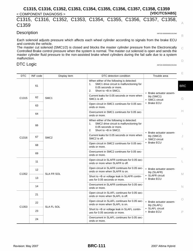
C1315, C1316, C1352, C1353, C1354, C1355, C1356, C1357, C1358, C1359[VDC/TCS/ABS]
C
D
E
G
H
I
J
K
L
M
A
B
RC
N
O
P
< COMPONENT DIAGNOSIS >
B
C1315, C1316, C1352, C1353, C1354, C1355, C1356, C1357, C1358,C1359
Description INFOID:0000000001501940
Each solenoid adjusts pressure which affects each wheel cylinder according to signals from the brake ECUand controls the vehicle.The master cut solenoid (SMC1/2) is closed and blocks the master cylinder pressure from the ElectronicallyControlled Brake control pressure when the system is normal. The master cut solenoid is open and sends themaster cylinder fluid pressure to the non-assisted brake wheel cylinders during the fail safe due to a systemmalfunction.
DTC Logic INFOID:0000000001501941
DTC INF code Display item DTC detection condition Trouble area
C1315
61
SMC1
When either of the following is detected:1. SMC1 drive circuit is malfunctioning for
0.05 seconds or more.2. Short to +B in SMC1.
• Brake actuator assem-bly (SMC1)
• SMC1 circuit• Brake ECU
62Current leaks for 0.05 seconds or more when SMC1 is off.
63Open circuit in SMC1 continues for 0.05 sec-onds or more.
64Overcurrent in SMC1 continues for 0.05 sec-onds or more.
C1316
66
SMC2
When either of the following is detected:1. SMC2 drive circuit is malfunctioning for
0.05 seconds or more.2. Short to +B in SMC2.
• Brake actuator assem-bly (SMC2)
• SMC2 circuit• Brake ECU
67Current leaks for 0.05 seconds or more when SMC2 is off.
68Open circuit in SMC2 continues for 0.05 sec-onds or more.
69Overcurrent in SMC2 continues for 0.05 sec-onds or more.
C1352
11
SLA FR SOL
Open circuit in SLAFR continues for 0.05 sec-onds or more when SLAFR is off.
• Brake actuator assem-bly (SLAFR)
• SLAFR circuit• Brake ECU
12Open circuit in SLAFR continues for 0.05 sec-onds or more when SLAFR is on.
13Short to +B or voltage leak in SLAFR contin-ues for 0.05 seconds or more.
14Overcurrent in SLAFR continues for 0.05 sec-onds or more.
C1353
21
SLA FL SOL
Open circuit in SLAFL continues for 0.05 sec-onds or more when SLAFL is off.
• Brake actuator assem-bly (SLAFL)
• SLAFL circuit• Brake ECU
22Open circuit in SLAFL continues for 0.05 sec-onds or more when SLAFL is on.
23Short to +B or voltage leak in SLAFL contin-ues for 0.05 seconds or more.
24Overcurrent in SLAFL continues for 0.05 sec-onds or more.
BRC-111

[VDC/TCS/ABS]C1315, C1316, C1352, C1353, C1354, C1355, C1356, C1357, C1358, C1359
< COMPONENT DIAGNOSIS >
Diagnosis Procedure INFOID:0000000001501942
CAUTION:When replacing the brake ECU or brake actuator assembly, perform initialization of linear solenoidvalve and calibration.
C1354
31
SLA RR SOL
Open circuit in SLARR continues for 0.05 sec-onds or more when SLARR is off.
• Brake actuator assem-bly (SLARR)
• SLARR circuit• Brake ECU
32Open circuit in SLARR continues for 0.05 sec-onds or more when SLARR is on.
33Short to +B or voltage leak in SLARR contin-ues for 0.05 seconds or more.
34Overcurrent in SLARR continues for 0.05 sec-onds or more.
C1355
41
SLA RL SOL
Open circuit in SLARL continues for 0.05 sec-onds or more when SLARL is off.
• Brake actuator assem-bly (SLARL)
• SLARL circuit• Brake ECU
42Open circuit in SLARL continues for 0.05 sec-onds or more when SLARL is on.
43Short to +B or voltage leak in SLARL contin-ues for 0.05 seconds or more.
44Overcurrent in SLARL continues for 0.05 sec-onds or more.
C1356
16
SLR FR SOL
Open circuit in SLRFR continues for 0.05 sec-onds or more when SLRFR is off.
• Brake actuator assem-bly (SLRFR)
• SLRFR circuit• Brake ECU
17Open circuit in SLRFR continues for 0.05 sec-onds or more when SLRFR is on.
18Short to +B or voltage leak in SLRFR contin-ues for 0.05 seconds or more.
19Overcurrent in SLRFR continues for 0.05 sec-onds or more.
C1357
26
SLR FL SOL
Open circuit in SLRFL continues for 0.05 sec-onds or more when SLRFL is off.
• Brake actuator assem-bly (SLRFL)
• SLRFL circuit• Brake ECU
27Open circuit in SLRFL continues for 0.05 sec-onds or more when SLRFL is on.
28Short to +B or voltage leak in SLRFL contin-ues for 0.05 seconds or more.
29Overcurrent in SLRFL continues for 0.05 sec-onds or more.
C1358
36
SLR RR SOL
Open circuit in SLRRR continues for 0.05 sec-onds or more when SLRRR is off.
• Brake actuator assem-bly (SLRRR)
• SLRRR circuit• Brake ECU
37Open circuit in SLRRR continues for 0.05 sec-onds or more when SLRRR is on.
38Short to +B or voltage leak in SLRRR contin-ues for 0.05 seconds or more.
39Overcurrent in SLRRR continues for 0.05 sec-onds or more.
C1359
46
SLR RL SOL
Open circuit in SLRRL continues for 0.05 sec-onds or more when SLRRL is off.
• Brake actuator assem-bly (SLRRL)
• SLRRL circuit• Brake ECU
47Open circuit in SLRRL continues for 0.05 sec-onds or more when SLRRL is on.
48Short to +B or voltage leak in SLRRL contin-ues for 0.05 seconds or more.
49Overcurrent in SLRRL continues for 0.05 sec-onds or more.
DTC INF code Display item DTC detection condition Trouble area
BRC-112

C1315, C1316, C1352, C1353, C1354, C1355, C1356, C1357, C1358, C1359[VDC/TCS/ABS]
C
D
E
G
H
I
J
K
L
M
A
B
RC
N
O
P
< COMPONENT DIAGNOSIS >
B
1.INSPECT BRAKE ACTUATOR ASSEMBLY
1. Disconnect the brake actuator connector.2. Measure the continuity according to the value(s) in the table below.
Is the inspection result normal?YES >> GO TO 2.NO >> Replace brake actuator assembly.
2.CHECK HARNESS AND CONNECTOR (BRAKE ECU – BRAKE ACTUATOR)
1. Turn the ignition switch OFF.2. Disconnect the brake ECU connectors.3. Measure the resistance to the value(s) in the table below.
Brake actuatorCondition Specified condition
Connector Terminal
E91 37 – 36 Always Existed
E91 36 – Ground Always Not existed
E91 19 – 20 Always Existed
E91 20 – Ground Always Not existed
E91 44 – 43 Always Existed
E91 44 – Ground Always Not existed
E91 21 – 22 Always Existed
E91 21 – Ground Always Not existed
E91 39 – 40 Always Existed
E91 39 – Ground Always Not existed
E91 41 – 42 Always Existed
E91 41 – Ground Always Not existed
E91 28 – 27 Always Existed
E91 28 – Ground Always Not existed
E91 21 – 22 Always Existed
E91 21 – Ground Always Not existed
E91 23 – 24 Always Existed
E91 23 – Ground Always Not existed
E91 25 – 26 Always Existed
E91 25 – Ground Always Not existed
Brake ECU Brake actuator— Condition Specified condition
Connector Terminal Connector Terminal
E60 42 E91 44 — Always Below 1 Ω
E60 42 — — Ground Always 10 kΩ or higher
E60 27 E91 43 — Always Below 1 Ω
E60 27 — — Ground Always 10 kΩ or higher
E60 41 E91 28 — Always Below 1 Ω
E60 41 — — Ground Always 10 kΩ or higher
E60 28 E91 27 — Always Below 1 Ω
E60 28 — — Ground Always 10 kΩ or higher
E61 86 E91 35 — Always Below 1 Ω
E61 86 — — Ground Always 10 kΩ or higher
BRC-113
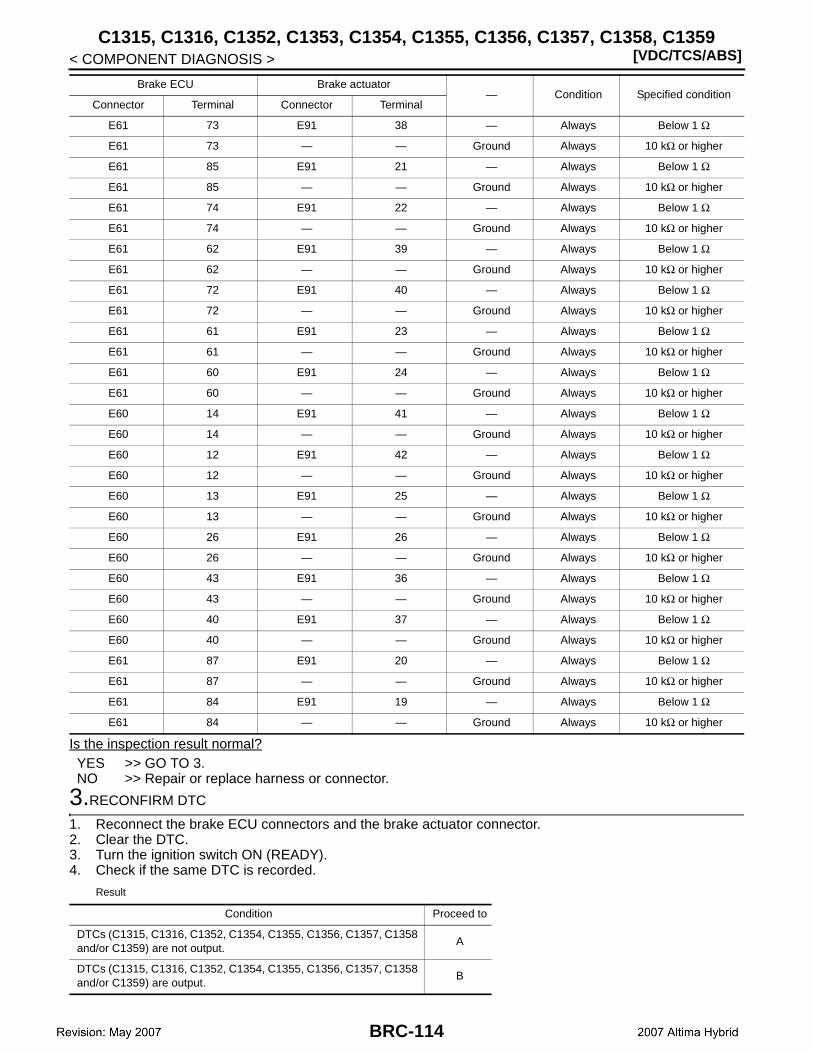
[VDC/TCS/ABS]C1315, C1316, C1352, C1353, C1354, C1355, C1356, C1357, C1358, C1359
< COMPONENT DIAGNOSIS >
Is the inspection result normal?YES >> GO TO 3.NO >> Repair or replace harness or connector.
3.RECONFIRM DTC
1. Reconnect the brake ECU connectors and the brake actuator connector.2. Clear the DTC.3. Turn the ignition switch ON (READY).4. Check if the same DTC is recorded.
Result
E61 73 E91 38 — Always Below 1 Ω
E61 73 — — Ground Always 10 kΩ or higher
E61 85 E91 21 — Always Below 1 Ω
E61 85 — — Ground Always 10 kΩ or higher
E61 74 E91 22 — Always Below 1 Ω
E61 74 — — Ground Always 10 kΩ or higher
E61 62 E91 39 — Always Below 1 Ω
E61 62 — — Ground Always 10 kΩ or higher
E61 72 E91 40 — Always Below 1 Ω
E61 72 — — Ground Always 10 kΩ or higher
E61 61 E91 23 — Always Below 1 Ω
E61 61 — — Ground Always 10 kΩ or higher
E61 60 E91 24 — Always Below 1 Ω
E61 60 — — Ground Always 10 kΩ or higher
E60 14 E91 41 — Always Below 1 Ω
E60 14 — — Ground Always 10 kΩ or higher
E60 12 E91 42 — Always Below 1 Ω
E60 12 — — Ground Always 10 kΩ or higher
E60 13 E91 25 — Always Below 1 Ω
E60 13 — — Ground Always 10 kΩ or higher
E60 26 E91 26 — Always Below 1 Ω
E60 26 — — Ground Always 10 kΩ or higher
E60 43 E91 36 — Always Below 1 Ω
E60 43 — — Ground Always 10 kΩ or higher
E60 40 E91 37 — Always Below 1 Ω
E60 40 — — Ground Always 10 kΩ or higher
E61 87 E91 20 — Always Below 1 Ω
E61 87 — — Ground Always 10 kΩ or higher
E61 84 E91 19 — Always Below 1 Ω
E61 84 — — Ground Always 10 kΩ or higher
Brake ECU Brake actuator— Condition Specified condition
Connector Terminal Connector Terminal
Condition Proceed to
DTCs (C1315, C1316, C1352, C1354, C1355, C1356, C1357, C1358 and/or C1359) are not output.
A
DTCs (C1315, C1316, C1352, C1354, C1355, C1356, C1357, C1358 and/or C1359) are output.
B
BRC-114
C1315, C1316, C1352, C1353, C1354, C1355, C1356, C1357, C1358, C1359[VDC/TCS/ABS]
C
D
E
G
H
I
J
K
L
M
A
B
RC
N
O
P
< COMPONENT DIAGNOSIS >
B
A >> Check for intermittent problems (symptom simulation).B >> Replace brake ECU.
Special Repair Requirement INFOID:0000000001501943
1.ZERO ADJUSTMENT FOR EACH SENSOR AND OFFSET LEANING FOR LINEAR SOLENOID VALVE
After erasing brake ECU memories, perform zero adjustment of following sensors and initialization of linearsolenoid valve.• Steering angle sensor: BRC-9, "PERFORM ZERO POINT OF STEERING ANGLE SENSOR : Description".• Yaw rate/side/decel G sensor: BRC-8, "PERFORM ZERO POINT OF YAW RATE/SIDE/DECEL G SENSOR
: Description".• Brake stroke sensor: BRC-9, "PERFORM ADJUSTMENT OF STROKE SENSOR : Description".• Linear solenoid valve: BRC-7, "PERFORM INITIALIZATION OF LINEAR SOLENOID VALVE AND CALI-
BRATION : Description".
>> END
BRC-115

[VDC/TCS/ABS]C1319
< COMPONENT DIAGNOSIS >
C1319
Description INFOID:0000000001501944
The stroke simulator solenoid (SCSS) generates pedal reactive effort during Electronically Controlled Brakecontrol. If one or more of the front wheels loses brake booster function, the simulator operation is prohibited.
DTC Logic INFOID:0000000001501945
Diagnosis Procedure INFOID:0000000001501946
CAUTION:When replacing the brake ECU, perform initialization of linear solenoid valve and calibration.
1.INSPECT STROKE SIMULATOR
1. Disconnect the brake simulator connector E90.2. Measure the resistance according to the value(s) in the table below.
Is the inspection result normal?YES >> GO TO 2.NO >> Replace brake simulator.
2.CHECK HARNESS AND CONNECTOR
1. Disconnect the brake ECU connector.2. Measure the resistance to the value(s) in the table below.
Is the inspection result normal?YES >> GO TO 3.NO >> Repair or replace harness or connector.
3.RECONFIRM DTC
1. Turn the ignition switch OFF.2. Reconnect the brake simulator connector.
DTC INF code Display item DTC detection condition Trouble area
C1319
71
SCSS
When either of the following is detected:1. SCSS drive circuit is malfunctioning for
0.05 seconds or more. 2. Short to +B in SCSS.
• Brake simulator• Brake simulator circuit• Brake ECU
72Current leaks for 0.05 seconds or more when SCSS is off.
73Open circuit in SCSS continues for 0.05 sec-onds or more.
74Overcurrent in SCSS continues for 0.05 sec-onds or more.
Brake simulatorCondition Specified condition
Connector Terminal
E90 1 – 2 Always 19 to 38 Ω
E90 1 – Ground Always 10 kΩ or higher
Brake ECU Brake simulator— Condition Specified condition
Connector Terminal Connector Terminal
E60 7 E90 2 — Always Below 1 Ω
E60 7 — — Ground Always 10 kΩ or higher
E60 44 E90 1 — Always Below 1 Ω
E60 44 — — Ground Always 10 kΩ or higher
BRC-116
C1319[VDC/TCS/ABS]
C
D
E
G
H
I
J
K
L
M
A
B
RC
N
O
P
< COMPONENT DIAGNOSIS >
B
3. Clear the DTC.4. Turn ignition switch ON (READY).5. Check if the same DTC is recorded.
Result
A >> Check for intermittent problems (symptom simulation).B >> Replace brake ECU.
Special Repair Requirement INFOID:0000000001501947
1.ZERO ADJUSTMENT FOR EACH SENSOR AND OFFSET LEANING FOR LINEAR SOLENOID VALVE
After erasing brake ECU memories, perform zero adjustment of following sensors and initialization of linearsolenoid valve.• Steering angle sensor: BRC-9, "PERFORM ZERO POINT OF STEERING ANGLE SENSOR : Description".• Yaw rate/side/decel G sensor: BRC-8, "PERFORM ZERO POINT OF YAW RATE/SIDE/DECEL G SENSOR
: Description".• Brake stroke sensor: BRC-9, "PERFORM ADJUSTMENT OF STROKE SENSOR : Description".• Linear solenoid valve: BRC-7, "PERFORM INITIALIZATION OF LINEAR SOLENOID VALVE AND CALI-
BRATION : Description".
>> END
Condition Proceed to
DTC (C1319) is not output. A
DTC (C1319) is output. B
BRC-117

[VDC/TCS/ABS]C1341, C1342, C1343, C1344
< COMPONENT DIAGNOSIS >
C1341, C1342, C1343, C1344
Description INFOID:0000000001501948
The brake ECU controls braking force according to the hybrid control system regenerative braking force andinputs the fluid pressure necessary for operating each wheel cylinder according to the wheel cylinder pressuresensor.DTCs may be stored if brake fluid leaks, the wheel cylinder vibrates due to uneven wear of the brake discrotor, or foreign matter enters the solenoid valve.DTCs may be stored if the line pressure drops during air bleeding.
DTC Logic INFOID:0000000001501949
Diagnosis Procedure INFOID:0000000001501950
CAUTION:When replacing the brake actuator assembly, perform initialization of linear solenoid valve and cali-bration.NOTE:When C1364 is output together with C1341, C1342, C1343 or C1344, inspect and repair the trouble areasindicated by C1364 first.
1.CHECK FOR BRAKE FLUID LEAKS
1. Check that there is no fluid leakage in the brake line between the brake actuator and the wheel cylinderwhich is the cause of DTCs.
2. Check that the brake is no dragging.NOTE:There is no fluid leakage or dragging.
DTC INF code Display item DTC detection condition Trouble area
C1341
551552
FR RH HYDRAULIC
Hydraulic pressure control on FR wheel has deteriorated.
• Fluid leakage• Brake actuator assem-
bly
553There is a malfunction, such as leakage in the pressure increase control valve of FR wheel.
• Fluid leakage• Disc rotor• Brake actuator assem-
bly554555
There is a malfunction, such as leakage in the pressure decrease control valve of FR wheel.
C1342
561562
FR LH HYDRAULIC
Hydraulic pressure control on FL wheel has deteriorated.
• Fluid leakage• Brake actuator assem-
bly
563There is a malfunction, such as leakage in the pressure increase control valve of FL wheel.
• Fluid leakage• Disc rotor• Brake actuator assem-
bly564565
There is a malfunction, such as leakage in the pressure decrease control valve of FL wheel.
C1343
571572
RR RH HYDRAULIC
Hydraulic pressure control on RR wheel has deteriorated.
• Fluid leakage• Brake actuator assem-
bly
573There is a malfunction, such as leakage in the pressure increase control valve of RR wheel.
• Fluid leakage• Disc rotor• Brake actuator assem-
bly574575
There is a malfunction, such as leakage in the pressure decrease control valve of RR wheel.
C1344
581582
RR LH HYDRAULIC
Hydraulic pressure control on RL wheel has deteriorated.
• Fluid leakage• Brake actuator assem-
bly
583There is a malfunction, such as leakage in the pressure increase control valve of RL wheel.
• Fluid leakage• Disc rotor• Brake actuator assem-
bly584585
There is a malfunction, such as leakage in the pressure decrease control valve of RL wheel.
BRC-118

C1341, C1342, C1343, C1344[VDC/TCS/ABS]
C
D
E
G
H
I
J
K
L
M
A
B
RC
N
O
P
< COMPONENT DIAGNOSIS >
B
Is the inspection result normal?YES >> GO TO 2.NO >> Repair or replace applicable part.
2.PERFORM AIR BLEEDING
Bleed the air from the front and rear brake system.
>> GO TO 3.
3.RECONFIRM DTC
1. Clear the DTC.2. Repeat the braking test under malfunction conditions recreated based on the Freeze Frame Data or cus-
tomer problem analysis.
Result
NOTE:DTC may be stored if foreign matter or air enters the solenoid valve.
A >> GO TO 4.B >> INSPECTION END
4.CHECK HARNESS AND CONNECTOR (BRAKE ECU – BODY GROUND)
1. Turn the ignition switch OFF.2. Disconnect the brake ECU connectors.3. Measure the resistance to the value(s) in the table below.
Is the inspection result normal?YES >> GO TO 5.NO >> Repair or replace harness or connector.
5.READ VALUE OF CONSULT-III (WHEEL CYLINDER PRESSURE SENSOR)
1. Reconnect the brake ECU connectors and the brake actuator connector.2. Install the brake fluid pressure tester [SST: KV991V0010 (J-39528)] and bleed air.3. Connect the CONSULT-III.4. Turn the ignition switch ON.
Condition Proceed to
DTCs (C1341, C1342, C1343 and/or C1344) are output. A
DTCs (C1341, C1342, C1343 and/or C1344) are not output. B
Brake ECUCondition Specified condition
Connector Terminal
E60 4 – Ground Always 10 kΩ or higher
E60 18 – Ground Always 10 kΩ or higher
E60 5 – Ground Always 10 kΩ or higher
E60 19 – Ground Always 10 kΩ or higher
E60 3 – Ground Always 10 kΩ or higher
E60 31 – Ground Always 10 kΩ or higher
E60 36 – Ground Always 10 kΩ or higher
E61 65 – Ground Always 10 kΩ or higher
E61 83 – Ground Always 10 kΩ or higher
E61 52 – Ground Always 10 kΩ or higher
E61 77 – Ground Always 10 kΩ or higher
E61 53 – Ground Always 10 kΩ or higher
E61 54 – Ground Always 10 kΩ or higher
BRC-119
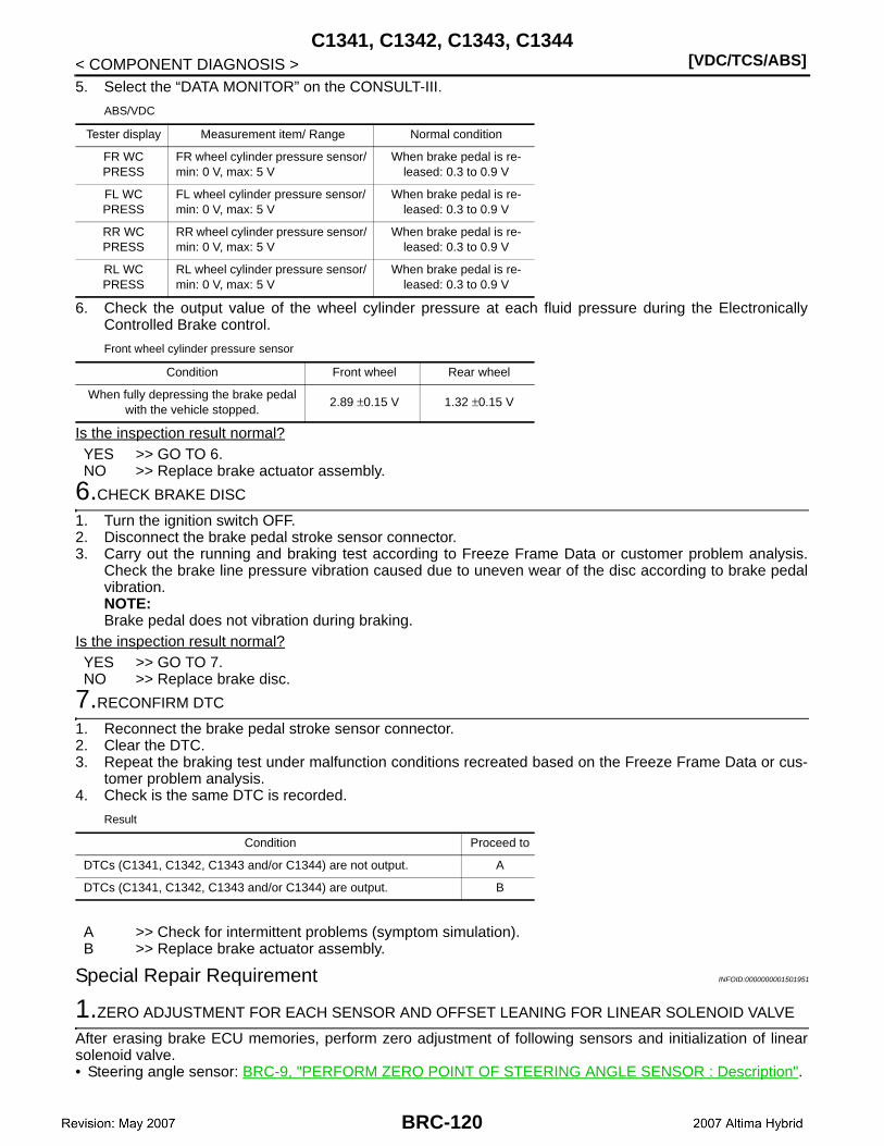
[VDC/TCS/ABS]C1341, C1342, C1343, C1344
< COMPONENT DIAGNOSIS >5. Select the “DATA MONITOR” on the CONSULT-III.
ABS/VDC
6. Check the output value of the wheel cylinder pressure at each fluid pressure during the ElectronicallyControlled Brake control.
Front wheel cylinder pressure sensor
Is the inspection result normal?YES >> GO TO 6.NO >> Replace brake actuator assembly.
6.CHECK BRAKE DISC
1. Turn the ignition switch OFF.2. Disconnect the brake pedal stroke sensor connector.3. Carry out the running and braking test according to Freeze Frame Data or customer problem analysis.
Check the brake line pressure vibration caused due to uneven wear of the disc according to brake pedalvibration.NOTE:Brake pedal does not vibration during braking.
Is the inspection result normal?YES >> GO TO 7.NO >> Replace brake disc.
7.RECONFIRM DTC
1. Reconnect the brake pedal stroke sensor connector.2. Clear the DTC.3. Repeat the braking test under malfunction conditions recreated based on the Freeze Frame Data or cus-
tomer problem analysis.4. Check is the same DTC is recorded.
Result
A >> Check for intermittent problems (symptom simulation).B >> Replace brake actuator assembly.
Special Repair Requirement INFOID:0000000001501951
1.ZERO ADJUSTMENT FOR EACH SENSOR AND OFFSET LEANING FOR LINEAR SOLENOID VALVE
After erasing brake ECU memories, perform zero adjustment of following sensors and initialization of linearsolenoid valve.• Steering angle sensor: BRC-9, "PERFORM ZERO POINT OF STEERING ANGLE SENSOR : Description".
Tester display Measurement item/ Range Normal condition
FR WC PRESS
FR wheel cylinder pressure sensor/ min: 0 V, max: 5 V
When brake pedal is re-leased: 0.3 to 0.9 V
FL WC PRESS
FL wheel cylinder pressure sensor/ min: 0 V, max: 5 V
When brake pedal is re-leased: 0.3 to 0.9 V
RR WC PRESS
RR wheel cylinder pressure sensor/ min: 0 V, max: 5 V
When brake pedal is re-leased: 0.3 to 0.9 V
RL WC PRESS
RL wheel cylinder pressure sensor/ min: 0 V, max: 5 V
When brake pedal is re-leased: 0.3 to 0.9 V
Condition Front wheel Rear wheel
When fully depressing the brake pedal with the vehicle stopped.
2.89 ±0.15 V 1.32 ±0.15 V
Condition Proceed to
DTCs (C1341, C1342, C1343 and/or C1344) are not output. A
DTCs (C1341, C1342, C1343 and/or C1344) are output. B
BRC-120
C1341, C1342, C1343, C1344[VDC/TCS/ABS]
C
D
E
G
H
I
J
K
L
M
A
B
RC
N
O
P
< COMPONENT DIAGNOSIS >
B
• Yaw rate/side/decel G sensor: BRC-8, "PERFORM ZERO POINT OF YAW RATE/SIDE/DECEL G SENSOR: Description".
• Brake stroke sensor: BRC-9, "PERFORM ADJUSTMENT OF STROKE SENSOR : Description".• Linear solenoid valve: BRC-7, "PERFORM INITIALIZATION OF LINEAR SOLENOID VALVE AND CALI-
BRATION : Description".
>> END
BRC-121

[VDC/TCS/ABS]C1345, C1368
< COMPONENT DIAGNOSIS >
C1345, C1368
Description INFOID:0000000001501952
The brake ECU stores and corrects the difference in each individual part such as the stroke sensor, actuatorsolenoids, and stroke simulator solenoid. Perform initialization of linear solenoid valve and calibration if theseparts are replaced.The brake ECU receives shift position P signals from the HV ECU through CAN communication system.The DTCs are cancelled when the result of linear valve offset learning is normal.
DTC Logic INFOID:0000000001501953
Diagnosis Procedure INFOID:0000000001501954
CAUTION:When replacing the brake actuator assembly, perform initialization of linear solenoid valve and cali-bration.
1.CHECK DTC
1. Clear the DTC.2. Turn the ignition switch OFF.3. Turn the ignition switch ON.4. Check that the DTCs (Electronicaly Controlled Brake and hybrid control system) are recorded.
Result
A >> GO TO 2.B >> Inspect hybrid control system.C >> Repair circuit indicated by output DTC.
2.PERFORM INITIALIZATION OF LINEAR SOLENOID VALVE AND CALIBRATION
Perform initialization of linear solenoid valve and calibration.
>> GO TO 3.
3.RECONFIRM DTC
1. Turn the ignition switch OFF.2. Clear the DTC.3. Turn the ignition switch ON.4. Check if the same DTC is recorded.
Result
DTC INF code Display item DTC detection condition Trouble area
C1345 — LINEAR VLV CALIBValue of initialization of linear solenoid valve and calibration for the FR, FL, RR, and RL wheels is not stored.
• Initialization of linear solenoid valve and cali-bration undone
• Brake ECUC1368 — LINEAR S/VValue of initialization of linear solenoid valve and calibration is not within the brake actua-tor′s standard value.
Condition Proceed to
DTCs (except C1345, C1368 and/or hybrid control system DTC) are not output.
A
Hybrid control system DTC is output. B
DTCs (except C1345 and/or C1368) are output. C
Condition Proceed to
DTCs (C1345 and/or C1368) are not output. A
DTCs (C1345 and/or C1368) are output. B
BRC-122
C1345, C1368[VDC/TCS/ABS]
C
D
E
G
H
I
J
K
L
M
A
B
RC
N
O
P
< COMPONENT DIAGNOSIS >
B
YES >> INSPECTION ENDNO >> Replace brake ECU.
Special Repair Requirement INFOID:0000000001501955
1.ZERO ADJUSTMENT FOR EACH SENSOR AND OFFSET LEANING FOR LINEAR SOLENOID VALVE
After erasing brake ECU memories, perform zero adjustment of following sensors and initialization of linearsolenoid valve.• Steering angle sensor: BRC-9, "PERFORM ZERO POINT OF STEERING ANGLE SENSOR : Description".• Yaw rate/side/decel G sensor: BRC-8, "PERFORM ZERO POINT OF YAW RATE/SIDE/DECEL G SENSOR
: Description".• Brake stroke sensor: BRC-9, "PERFORM ADJUSTMENT OF STROKE SENSOR : Description".• Linear solenoid valve: BRC-7, "PERFORM INITIALIZATION OF LINEAR SOLENOID VALVE AND CALI-
BRATION : Description".
>> END
BRC-123

[VDC/TCS/ABS]C1365
< COMPONENT DIAGNOSIS >
C1365
Description INFOID:0000000001501956
The accumulator pressure sensor is built into the brake actuator.The brake ECU detects the accumulator pressure from the data sent from the accumulator pressure sensor,and then runs and stops the pump motor by operating the motor relay.DTCs may be output if the accumulator pressure drops due to frequent braking (this is not a malfunction).
DTC Logic INFOID:0000000001501957
Diagnosis Procedure INFOID:0000000001501958
CAUTION:When replacing the brake ECU or brake actuator assembly, perform initialization of linear solenoidvalve and calibrating.
1.CHECK HARNESS AND CONNECTOR (BRAKE ECU – BRAKE ACTUATOR)
1. Disconnect the brake ECU connector and the brake actuator connector.2. Measure the resistance according to the value(s) in the table below.
DTC INF code Display item DTC detection condition Possible cause
C1365
211
ACC PRESS SEN
Sensor power 1 (VCM1) voltage is 4.7 V or less or 5.3 V or more for at least 0.05 seconds.
• Brake actuator assem-bly (Accumulator pres-sure sensor)
• Accumulator pressure sensor circuit
• Accumulator pressure sensor power supply
• Brake actuator assem-bly
• Brake ECU
212
Ratio of accumulator pressure sensor output voltage (PACC) to sensor power 1 (VCM1) voltage is 5% or less or 90.5% or more for at least 0.05 seconds.
214
Total wheel cylinder pressure sensor exceeds 18 MPa after depressing brake pedal, but ac-cumulator pressure sensor output voltage (PACC) changes less than 0.5 MPa for at least 0.5 seconds.
215
Ratio of accumulator pressure sensor output voltage (PACC) to sensor power 1 (VCM1) voltage is 90.5% or less for at least 0.1 second during self diagnosis.
Brake ECU Brake actuator— Condition Specified condition
Connector Terminal Connector Terminal
E60 4 E91 14 — Always Below 1 Ω
E60 4 — — Ground Always 10 kΩ or higher
E60 18 E91 10 — Always Below 1 Ω
E60 18 — — Ground Always 10 kΩ or higher
E60 19 E91 15 — Always Below 1 Ω
E60 19 — — Ground Always 10 kΩ or higher
E60 36 E91 12 — Always Below 1 Ω
E60 36 — — Ground Always 10 kΩ or higher
E60 31 E91 13 — Always Below 1 Ω
E60 31 — — Ground Always 10 kΩ or higher
E60 3 E91 9 — Always Below 1 Ω
E60 3 — — Ground Always 10 kΩ or higher
E60 5 E91 11 — Always Below 1 Ω
E60 5 — — Ground Always 10 kΩ or higher
BRC-124

C1365[VDC/TCS/ABS]
C
D
E
G
H
I
J
K
L
M
A
B
RC
N
O
P
< COMPONENT DIAGNOSIS >
B
Is the inspection result normal?YES >> GO TO 2.NO >> Repair or replace harness or connector.
2.READ VALUE OF CONSULT-III (ACCUMULATOR PRESSURE SENSOR)
1. Turn the ignition switch OFF.2. Connect the CONSULT-III.3. Turn the ignition switch ON.4. Select the “DATA MONITOR” on the CONSULT-III.
ABS/VDC:
5. Depress the brake pedal 4 or 5 times to operate the pump motor, and check the output value on the CON-SULT-III with the motor stopped (not braking).NOTE:Accumulator pressure sensor voltage does not drop.
Is the inspection result normal?YES >> GO TO 3.NO >> Replace brake actuator assembly.
3.RECONFIRM DTC
1. Turn the ignition switch OFF.2. Clear the DTC.3. Perform the road and braking test.4. Check if the same DTC is recorded.
Result
A >> Check for intermittent problems (symptom simulation).B >> Replace brake ECU.
Special Repair Requirement INFOID:0000000001501959
1.ZERO ADJUSTMENT FOR EACH SENSOR AND OFFSET LEANING FOR LINEAR SOLENOID VALVE
After erasing brake ECU memories, perform zero adjustment of following sensors and initialization of linearsolenoid valve.• Steering angle sensor: BRC-9, "PERFORM ZERO POINT OF STEERING ANGLE SENSOR : Description".• Yaw rate/side/decel G sensor: BRC-8, "PERFORM ZERO POINT OF YAW RATE/SIDE/DECEL G SENSOR
: Description".• Brake stroke sensor: BRC-9, "PERFORM ADJUSTMENT OF STROKE SENSOR : Description".• Linear solenoid valve: BRC-7, "PERFORM INITIALIZATION OF LINEAR SOLENOID VALVE AND CALI-
BRATION : Description".
>> END
Tester display Measurement item/ Range Normal condition
ACC PRESS SENAccumulator pressure sensor/ min: 0 V, max: 5 V
Specified value: 3.3 to 4.7 V
Condition Proceed to
DTC (C1365) is not output. A
DTC (C1365) is output. B
BRC-125
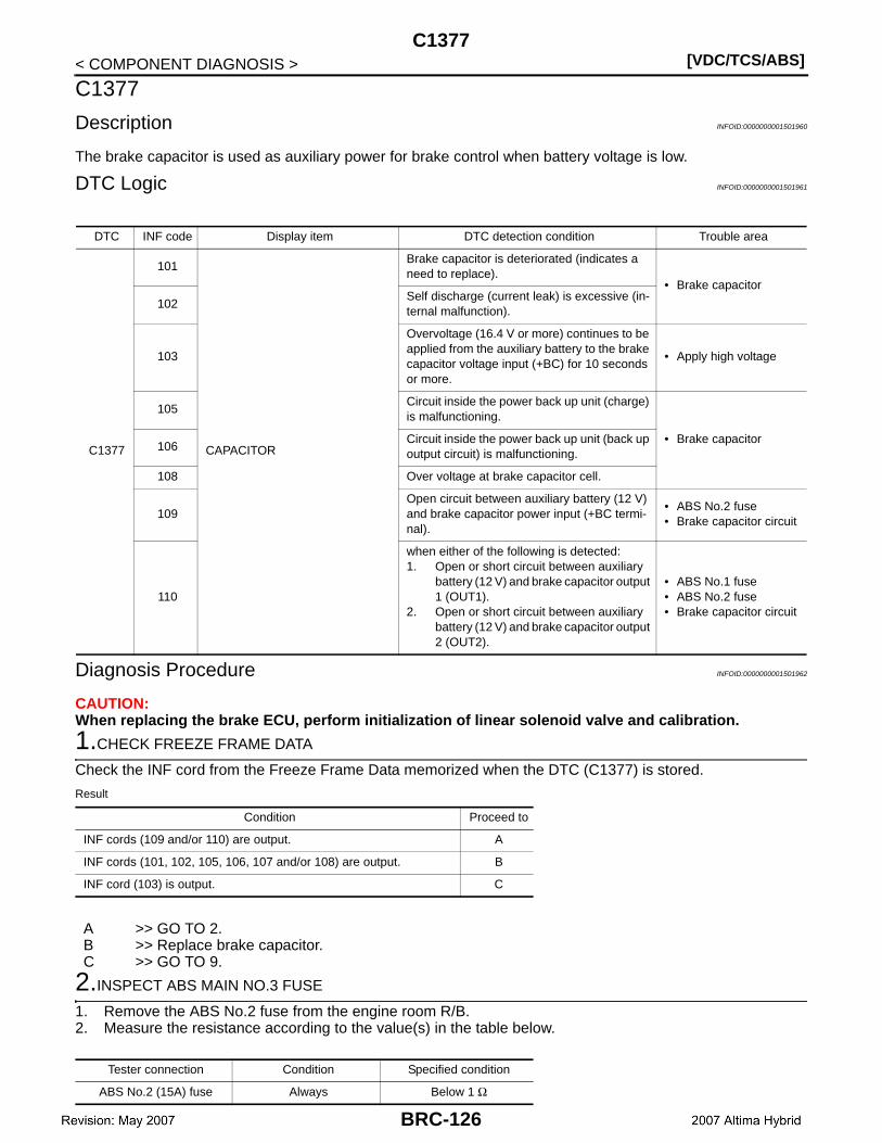
[VDC/TCS/ABS]C1377
< COMPONENT DIAGNOSIS >
C1377
Description INFOID:0000000001501960
The brake capacitor is used as auxiliary power for brake control when battery voltage is low.
DTC Logic INFOID:0000000001501961
Diagnosis Procedure INFOID:0000000001501962
CAUTION:When replacing the brake ECU, perform initialization of linear solenoid valve and calibration.
1.CHECK FREEZE FRAME DATA
Check the INF cord from the Freeze Frame Data memorized when the DTC (C1377) is stored.
Result
A >> GO TO 2.B >> Replace brake capacitor.C >> GO TO 9.
2.INSPECT ABS MAIN NO.3 FUSE
1. Remove the ABS No.2 fuse from the engine room R/B.2. Measure the resistance according to the value(s) in the table below.
DTC INF code Display item DTC detection condition Trouble area
C1377
101
CAPACITOR
Brake capacitor is deteriorated (indicates a need to replace).
• Brake capacitor
102Self discharge (current leak) is excessive (in-ternal malfunction).
103
Overvoltage (16.4 V or more) continues to be applied from the auxiliary battery to the brake capacitor voltage input (+BC) for 10 seconds or more.
• Apply high voltage
105Circuit inside the power back up unit (charge) is malfunctioning.
• Brake capacitor106
Circuit inside the power back up unit (back up output circuit) is malfunctioning.
108 Over voltage at brake capacitor cell.
109Open circuit between auxiliary battery (12 V) and brake capacitor power input (+BC termi-nal).
• ABS No.2 fuse• Brake capacitor circuit
110
when either of the following is detected:1. Open or short circuit between auxiliary
battery (12 V) and brake capacitor output 1 (OUT1).
2. Open or short circuit between auxiliary battery (12 V) and brake capacitor output 2 (OUT2).
• ABS No.1 fuse• ABS No.2 fuse• Brake capacitor circuit
Condition Proceed to
INF cords (109 and/or 110) are output. A
INF cords (101, 102, 105, 106, 107 and/or 108) are output. B
INF cord (103) is output. C
Tester connection Condition Specified condition
ABS No.2 (15A) fuse Always Below 1 Ω
BRC-126
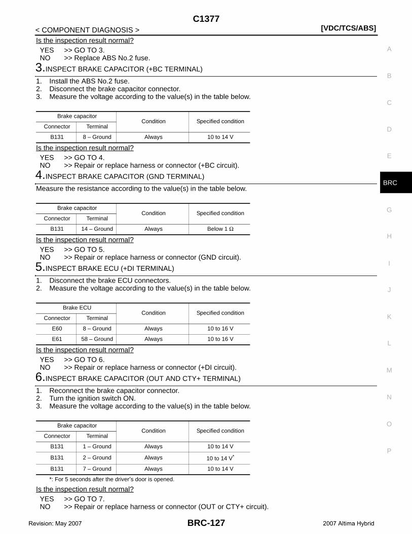
C1377[VDC/TCS/ABS]
C
D
E
G
H
I
J
K
L
M
A
B
RC
N
O
P
< COMPONENT DIAGNOSIS >
B
Is the inspection result normal?YES >> GO TO 3.NO >> Replace ABS No.2 fuse.
3.INSPECT BRAKE CAPACITOR (+BC TERMINAL)
1. Install the ABS No.2 fuse.2. Disconnect the brake capacitor connector.3. Measure the voltage according to the value(s) in the table below.
Is the inspection result normal?YES >> GO TO 4.NO >> Repair or replace harness or connector (+BC circuit).
4.INSPECT BRAKE CAPACITOR (GND TERMINAL)
Measure the resistance according to the value(s) in the table below.
Is the inspection result normal?YES >> GO TO 5.NO >> Repair or replace harness or connector (GND circuit).
5.INSPECT BRAKE ECU (+DI TERMINAL)
1. Disconnect the brake ECU connectors.2. Measure the voltage according to the value(s) in the table below.
Is the inspection result normal?YES >> GO TO 6.NO >> Repair or replace harness or connector (+DI circuit).
6.INSPECT BRAKE CAPACITOR (OUT AND CTY+ TERMINAL)
1. Reconnect the brake capacitor connector.2. Turn the ignition switch ON.3. Measure the voltage according to the value(s) in the table below.
*: For 5 seconds after the driver′s door is opened.
Is the inspection result normal?YES >> GO TO 7.NO >> Repair or replace harness or connector (OUT or CTY+ circuit).
Brake capacitorCondition Specified condition
Connector Terminal
B131 8 – Ground Always 10 to 14 V
Brake capacitorCondition Specified condition
Connector Terminal
B131 14 – Ground Always Below 1 Ω
Brake ECUCondition Specified condition
Connector Terminal
E60 8 – Ground Always 10 to 16 V
E61 58 – Ground Always 10 to 16 V
Brake capacitorCondition Specified condition
Connector Terminal
B131 1 – Ground Always 10 to 14 V
B131 2 – Ground Always 10 to 14 V*
B131 7 – Ground Always 10 to 14 V
BRC-127
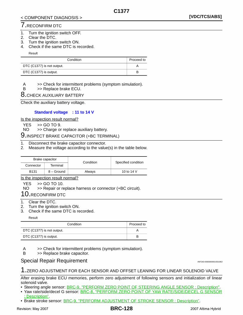
[VDC/TCS/ABS]C1377
< COMPONENT DIAGNOSIS >
7.RECONFIRM DTC
1. Turn the ignition switch OFF.2. Clear the DTC.3. Turn the ignition switch ON.4. Check if the same DTC is recorded.
Result
A >> Check for intermittent problems (symptom simulation).B >> Replace brake ECU.
8.CHECK AUXILIARY BATTERY
Check the auxiliary battery voltage.
Is the inspection result normal?YES >> GO TO 9.NO >> Charge or replace auxiliary battery.
9.INSPECT BRAKE CAPACITOR (+BC TERMINAL)
1. Disconnect the brake capacitor connector.2. Measure the voltage according to the value(s) in the table below.
Is the inspection result normal?YES >> GO TO 10.NO >> Repair or replace harness or connector (+BC circuit).
10.RECONFIRM DTC
1. Clear the DTC.2. Turn the ignition switch ON.3. Check if the same DTC is recorded.
Result
A >> Check for intermittent problems (symptom simulation).B >> Replace brake capacitor.
Special Repair Requirement INFOID:0000000001501963
1.ZERO ADJUSTMENT FOR EACH SENSOR AND OFFSET LEANING FOR LINEAR SOLENOID VALVE
After erasing brake ECU memories, perform zero adjustment of following sensors and initialization of linearsolenoid valve.• Steering angle sensor: BRC-9, "PERFORM ZERO POINT OF STEERING ANGLE SENSOR : Description".• Yaw rate/side/decel G sensor: BRC-8, "PERFORM ZERO POINT OF YAW RATE/SIDE/DECEL G SENSOR
: Description".• Brake stroke sensor: BRC-9, "PERFORM ADJUSTMENT OF STROKE SENSOR : Description".
Condition Proceed to
DTC (C1377) is not output. A
DTC (C1377) is output. B
Standard voltage : 11 to 14 V
Brake capacitorCondition Specified condition
Connector Terminal
B131 8 – Ground Always 10 to 14 V
Condition Proceed to
DTC (C1377) is not output. A
DTC (C1377) is output. B
BRC-128

C1377[VDC/TCS/ABS]
C
D
E
G
H
I
J
K
L
M
A
B
RC
N
O
P
< COMPONENT DIAGNOSIS >
B
• Linear solenoid valve: BRC-7, "PERFORM INITIALIZATION OF LINEAR SOLENOID VALVE AND CALI-BRATION : Description".
>> END
BRC-129
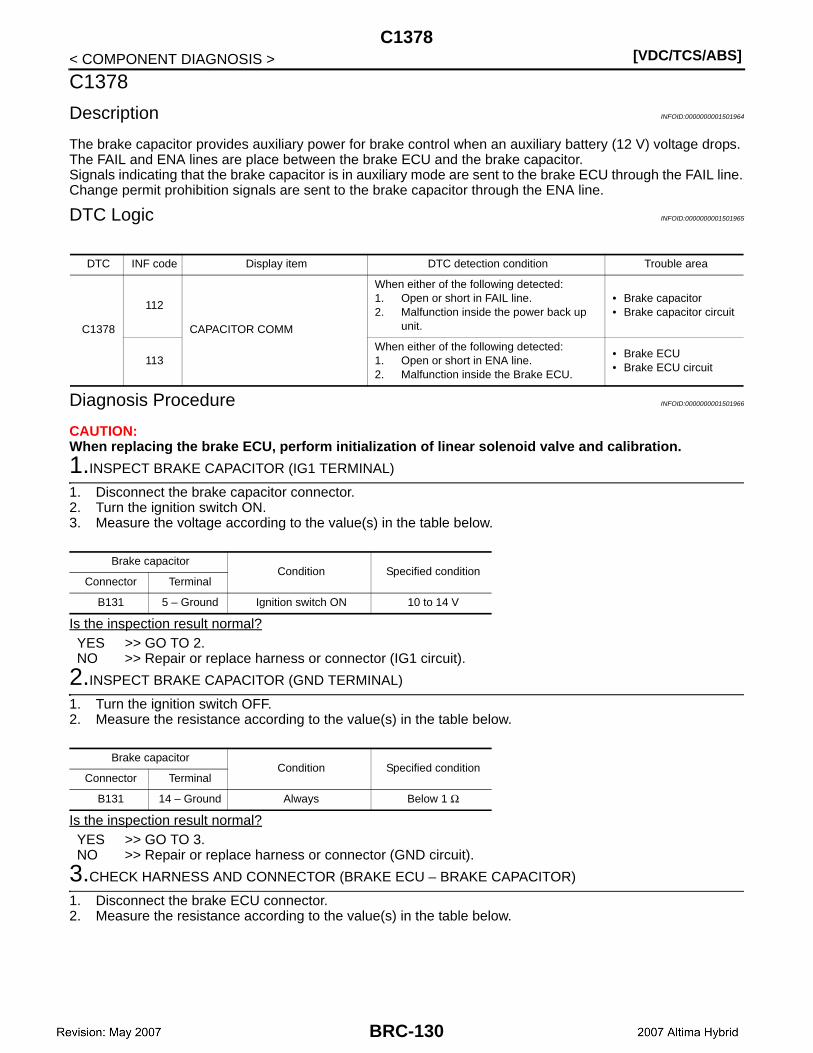
[VDC/TCS/ABS]C1378
< COMPONENT DIAGNOSIS >
C1378
Description INFOID:0000000001501964
The brake capacitor provides auxiliary power for brake control when an auxiliary battery (12 V) voltage drops.The FAIL and ENA lines are place between the brake ECU and the brake capacitor.Signals indicating that the brake capacitor is in auxiliary mode are sent to the brake ECU through the FAIL line.Change permit prohibition signals are sent to the brake capacitor through the ENA line.
DTC Logic INFOID:0000000001501965
Diagnosis Procedure INFOID:0000000001501966
CAUTION:When replacing the brake ECU, perform initialization of linear solenoid valve and calibration.
1.INSPECT BRAKE CAPACITOR (IG1 TERMINAL)
1. Disconnect the brake capacitor connector.2. Turn the ignition switch ON.3. Measure the voltage according to the value(s) in the table below.
Is the inspection result normal?YES >> GO TO 2.NO >> Repair or replace harness or connector (IG1 circuit).
2.INSPECT BRAKE CAPACITOR (GND TERMINAL)
1. Turn the ignition switch OFF.2. Measure the resistance according to the value(s) in the table below.
Is the inspection result normal?YES >> GO TO 3.NO >> Repair or replace harness or connector (GND circuit).
3.CHECK HARNESS AND CONNECTOR (BRAKE ECU – BRAKE CAPACITOR)
1. Disconnect the brake ECU connector.2. Measure the resistance according to the value(s) in the table below.
DTC INF code Display item DTC detection condition Trouble area
C1378
112
CAPACITOR COMM
When either of the following detected:1. Open or short in FAIL line.2. Malfunction inside the power back up
unit.
• Brake capacitor• Brake capacitor circuit
113When either of the following detected:1. Open or short in ENA line.2. Malfunction inside the Brake ECU.
• Brake ECU• Brake ECU circuit
Brake capacitorCondition Specified condition
Connector Terminal
B131 5 – Ground Ignition switch ON 10 to 14 V
Brake capacitorCondition Specified condition
Connector Terminal
B131 14 – Ground Always Below 1 Ω
BRC-130

C1378[VDC/TCS/ABS]
C
D
E
G
H
I
J
K
L
M
A
B
RC
N
O
P
< COMPONENT DIAGNOSIS >
B
Is the inspection result normal?YES >> GO TO 4.NO >> Repair or replace harness or connector.
4.RECONFIRM DTC
1. Reconnect the brake ECU connector and the brake capacitor connector.2. Clear the DTC.3. Turn the ignition switch ON.4. Check if the same DTC is recorded.
Result
A >> GO TO 5.B >> Check for intermittent problems (symptom simulation).
5.CHECK FREEZE FRAME DATA
Check the INF code from the Freeze Frame Data memorized when the DTC (1378) is stored.
Result
A >> Replace brake ECU.B >> Replace brake capacitor.
Special Repair Requirement INFOID:0000000001501967
1.ZERO ADJUSTMENT FOR EACH SENSOR AND OFFSET LEANING FOR LINEAR SOLENOID VALVE
After erasing brake ECU memories, perform zero adjustment of following sensors and initialization of linearsolenoid valve.• Steering angle sensor: BRC-9, "PERFORM ZERO POINT OF STEERING ANGLE SENSOR : Description".• Yaw rate/side/decel G sensor: BRC-8, "PERFORM ZERO POINT OF YAW RATE/SIDE/DECEL G SENSOR
: Description".• Brake stroke sensor: BRC-9, "PERFORM ADJUSTMENT OF STROKE SENSOR : Description".• Linear solenoid valve: BRC-7, "PERFORM INITIALIZATION OF LINEAR SOLENOID VALVE AND CALI-
BRATION : Description".
>> END
Brake ECU Brake capacitor— Condition Specified condition
Connector Terminal Connector Terminal
E60 24 B131 1 — Always Below 1 Ω
E60 24 — — Ground Always 10 kΩ or higher
E60 32 B131 2 — Always Below 1 Ω
E60 32 — — Ground Always 10 kΩ or higher
E60 37 B131 12 — Always Below 1 Ω
E60 37 — — Ground Always 10 kΩ or higher
E60 22 B131 13 — Always Below 1 Ω
E60 22 — — Ground Always 10 kΩ or higher
Condition Proceed to
DTC (C1378) is output. A
DTC (C1378) is not output. B
Condition Proceed to
INF code (112) is not output. A
INF code (112) is output. B
BRC-131
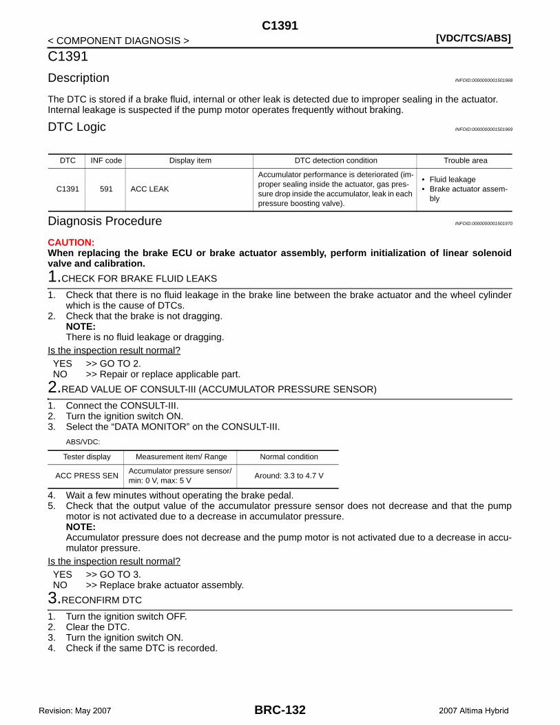
[VDC/TCS/ABS]C1391
< COMPONENT DIAGNOSIS >
C1391
Description INFOID:0000000001501968
The DTC is stored if a brake fluid, internal or other leak is detected due to improper sealing in the actuator.Internal leakage is suspected if the pump motor operates frequently without braking.
DTC Logic INFOID:0000000001501969
Diagnosis Procedure INFOID:0000000001501970
CAUTION:When replacing the brake ECU or brake actuator assembly, perform initialization of linear solenoidvalve and calibration.
1.CHECK FOR BRAKE FLUID LEAKS
1. Check that there is no fluid leakage in the brake line between the brake actuator and the wheel cylinderwhich is the cause of DTCs.
2. Check that the brake is not dragging.NOTE:There is no fluid leakage or dragging.
Is the inspection result normal?YES >> GO TO 2.NO >> Repair or replace applicable part.
2.READ VALUE OF CONSULT-III (ACCUMULATOR PRESSURE SENSOR)
1. Connect the CONSULT-III.2. Turn the ignition switch ON.3. Select the “DATA MONITOR” on the CONSULT-III.
ABS/VDC:
4. Wait a few minutes without operating the brake pedal.5. Check that the output value of the accumulator pressure sensor does not decrease and that the pump
motor is not activated due to a decrease in accumulator pressure.NOTE:Accumulator pressure does not decrease and the pump motor is not activated due to a decrease in accu-mulator pressure.
Is the inspection result normal?YES >> GO TO 3.NO >> Replace brake actuator assembly.
3.RECONFIRM DTC
1. Turn the ignition switch OFF.2. Clear the DTC.3. Turn the ignition switch ON.4. Check if the same DTC is recorded.
DTC INF code Display item DTC detection condition Trouble area
C1391 591 ACC LEAK
Accumulator performance is deteriorated (im-proper sealing inside the actuator, gas pres-sure drop inside the accumulator, leak in each pressure boosting valve).
• Fluid leakage• Brake actuator assem-
bly
Tester display Measurement item/ Range Normal condition
ACC PRESS SENAccumulator pressure sensor/ min: 0 V, max: 5 V
Around: 3.3 to 4.7 V
BRC-132
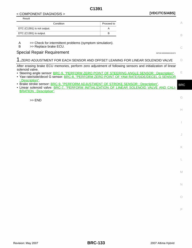
C1391[VDC/TCS/ABS]
C
D
E
G
H
I
J
K
L
M
A
B
RC
N
O
P
< COMPONENT DIAGNOSIS >
B
Result
A >> Check for intermittent problems (symptom simulation).B >> Replace brake ECU.
Special Repair Requirement INFOID:0000000001501971
1.ZERO ADJUSTMENT FOR EACH SENSOR AND OFFSET LEANING FOR LINEAR SOLENOID VALVE
After erasing brake ECU memories, perform zero adjustment of following sensors and initialization of linearsolenoid valve.• Steering angle sensor: BRC-9, "PERFORM ZERO POINT OF STEERING ANGLE SENSOR : Description".• Yaw rate/side/decel G sensor: BRC-8, "PERFORM ZERO POINT OF YAW RATE/SIDE/DECEL G SENSOR
: Description".• Brake stroke sensor: BRC-9, "PERFORM ADJUSTMENT OF STROKE SENSOR : Description".• Linear solenoid valve: BRC-7, "PERFORM INITIALIZATION OF LINEAR SOLENOID VALVE AND CALI-
BRATION : Description".
>> END
Condition Proceed to
DTC (C1391) is not output. A
DTC (C1391) is output. B
BRC-133
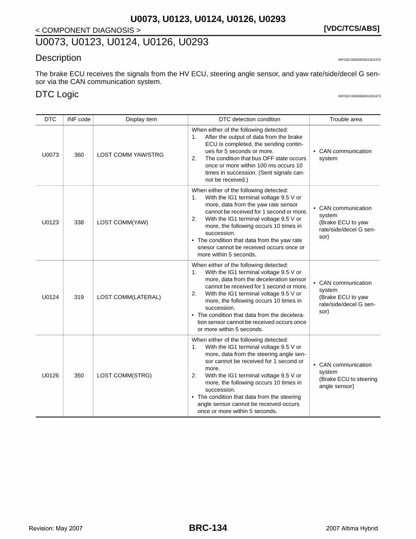
[VDC/TCS/ABS]U0073, U0123, U0124, U0126, U0293
< COMPONENT DIAGNOSIS >
U0073, U0123, U0124, U0126, U0293
Description INFOID:0000000001501972
The brake ECU receives the signals from the HV ECU, steering angle sensor, and yaw rate/side/decel G sen-sor via the CAN communication system.
DTC Logic INFOID:0000000001501973
DTC INF code Display item DTC detection condition Trouble area
U0073 360 LOST COMM YAW/STRG
When either of the following detected:1. After the output of data from the brake
ECU is completed, the sending contin-ues for 5 seconds or more.
2. The condition that bus OFF state occurs once or more within 100 ms occurs 10 times in succession. (Sent signals can-not be received.)
• CAN communication system
U0123 338 LOST COMM(YAW)
When either of the following detected:1. With the IG1 terminal voltage 9.5 V or
more, data from the yaw rate sensor cannot be received for 1 second or more.
2. With the IG1 terminal voltage 9.5 V or more, the following occurs 10 times in succession.
• The condition that data from the yaw rate snesor cannot be received occurs once or more within 5 seconds.
• CAN communication system(Brake ECU to yaw rate/side/decel G sen-sor)
U0124 319 LOST COMM(LATERAL)
When either of the following detected:1. With the IG1 terminal voltage 9.5 V or
more, data from the deceleration sensor cannot be received for 1 second or more.
2. With the IG1 terminal voltage 9.5 V or more, the following occurs 10 times in succession.
• The condition that data from the decelera-tion sensor cannot be received occurs once or more within 5 seconds.
• CAN communication system(Brake ECU to yaw rate/side/decel G sen-sor)
U0126 350 LOST COMM(STRG)
When either of the following detected:1. With the IG1 terminal voltage 9.5 V or
more, data from the steering angle sen-sor cannot be received for 1 second or more.
2. With the IG1 terminal voltage 9.5 V or more, the following occurs 10 times in succession.
• The condition that data from the steering angle sensor cannot be received occurs once or more within 5 seconds.
• CAN communication system(Brake ECU to steering angle sensor)
BRC-134
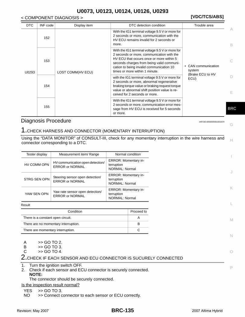
U0073, U0123, U0124, U0126, U0293[VDC/TCS/ABS]
C
D
E
G
H
I
J
K
L
M
A
B
RC
N
O
P
< COMPONENT DIAGNOSIS >
B
Diagnosis Procedure INFOID:0000000001501974
1.CHECK HARNESS AND CONNECTOR (MOMENTARY INTERRUPTION)
Using the “DATA MONITOR” of CONSULT-III, check for any momentary interruption in the wire harness andconnector corresponding to a DTC.
Result
A >> GO TO 2.B >> GO TO 3.C >> GO TO 4.
2.CHECK IF EACH SENSOR AND ECU CONNECTOR IS SUCURELY CONNECTED
1. Turn the ignition switch OFF.2. Check if each sensor and ECU connector is securely connected.
NOTE:The connector should be securely connected.
Is the inspection result normal?YES >> GO TO 3.NO >> Connect connector to each sensor or ECU correctly.
U0293
152
LOST COMM(HV ECU)
With the IG1 terminal voltage 9.5 V or more for 2 seconds or more, communication with the HV ECU remains invalid for 2 seconds or more.
• CAN communication system(Brake ECU to HV ECU)
153
With the IG1 terminal voltage 9.5 V or more for 2 seconds or more, communication with the HV ECU that occurs once or more within 5 seconds charges from being valid communi-cation to being invalid communication 10 times or more within 1 minute.
154
with the IG1 terminal voltage 9.5 V or more for 2 seconds or more, abnormal regenerative braking torque value or braking request torque value or abnormal shift position value is re-ceived for 2 seconds or more.
155
With the IG1 terminal voltage 9.5 V or more for 2 seconds or more, communication error mes-sage from HV ECU is received for 5 seconds or more.
DTC INF code Display item DTC detection condition Trouble area
Tester display Measurement item/ Range Normal condition
HV COMM OPNHV communication open detection/ ERROR or NORMAL
ERROR: Momentary in-terruptionNORMAL: Normal
STRG SEN OPNSteering sensor open detection/ ERROR or NORMAL
ERROR: Momentary in-terruptionNORMAL: Normal
YAW SEN OPNYaw rate sensor open detection/ ERROR or NORMAL
ERROR: Momentary in-terruptionNORMAL: Normal
Condition Proceed to
There is a constant open circuit. A
There are no momentary interruption. B
There are momentary interruption. C
BRC-135

[VDC/TCS/ABS]U0073, U0123, U0124, U0126, U0293
< COMPONENT DIAGNOSIS >
3.RECONFIRM DTC
1. Turn the ignition switch OFF.2. Record the output DTCs (for ABS, VDC, Electronically Controlled Brake, and CAN communication).
NOTE:If the CAN communication system DTC and the relevant sensor DTCs are output simultaneously, trouble-shoot the relevant sensor DTCs (for ABS, VDC and Electronically Controlled Brake) after the CAN com-munication system returns to normal.
Result
A >> Inspect CAN communication system.B >> Repair circuit indicated by output DTC.C >> Check for intermittent problems (symptom simulation).
4.REPAIR OR REPLACE HARNESS OR CONNECTOR
1. Turn the ignition switch OFF.2. Repair or replace the harness or connector.3. Check for any momentary interruption between the brake ECU and each sensor or ECU.4. Check that there is no momentary interruption.
>> GO TO 5.
5.RECONFIRM DTC
1. Turn the ignition switch OFF.2. Clear the DTC.3. Turn the ignition switch ON (READY).4. Drive the vehicle and turn the steering wheel to the right and left at a speed of 15 km/h (9 MPH) or more.5. Check that no CAN communication system DTC is output.6. If ABS, VDC and Electronically Controlled Brake DTCs are output, record them.
Result
NOTE:The CAN communication system must be normal when repairing each sensor DTC (for ABS, VDC andElectronically Controlled Brake).
A >> Inspect CAN communication system.B >> Repair circuit indicated by output DTC.C >> INSPECTION END
Condition Proceed to
DTC (CAN communication system DTC) is output. A
DTC (ABS, VDC and/or Electronically Controlled Brake DTC) is out-put.
B
DTC is not output. C
Condition Proceed to
DTC output for the CAN communication system. A
No DTC is output (ABS, VDC and/or Electronically Controlled Brake DTC is output).
B
No DTC is output (No ABS, VDC and/or Electronically Controlled Brake DTC is output).
C
BRC-136
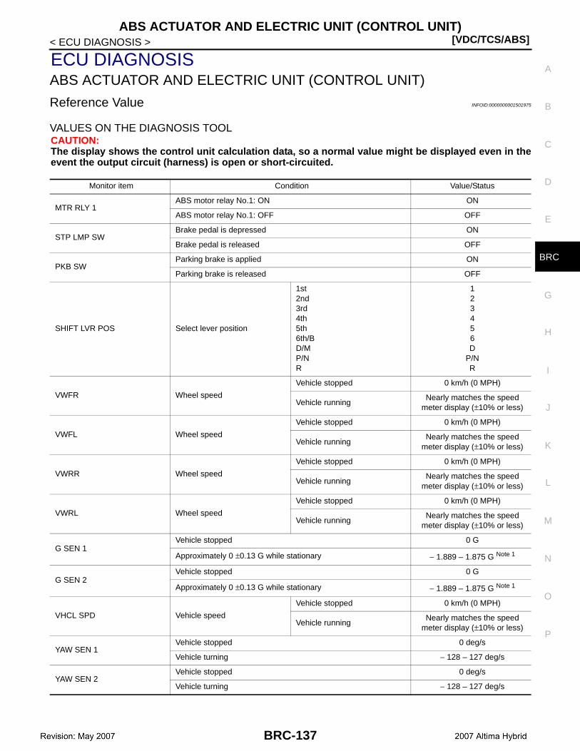
ABS ACTUATOR AND ELECTRIC UNIT (CONTROL UNIT)[VDC/TCS/ABS]
C
D
E
G
H
I
J
K
L
M
A
B
RC
N
O
P
< ECU DIAGNOSIS >
B
ECU DIAGNOSISABS ACTUATOR AND ELECTRIC UNIT (CONTROL UNIT)
Reference Value INFOID:0000000001501975
VALUES ON THE DIAGNOSIS TOOLCAUTION:The display shows the control unit calculation data, so a normal value might be displayed even in theevent the output circuit (harness) is open or short-circuited.
Monitor item Condition Value/Status
MTR RLY 1ABS motor relay No.1: ON ON
ABS motor relay No.1: OFF OFF
STP LMP SWBrake pedal is depressed ON
Brake pedal is released OFF
PKB SWParking brake is applied ON
Parking brake is released OFF
SHIFT LVR POS Select lever position
1st2nd3rd4th5th6th/BD/MP/NR
123456D
P/NR
VWFR Wheel speed
Vehicle stopped 0 km/h (0 MPH)
Vehicle runningNearly matches the speed
meter display (±10% or less)
VWFL Wheel speed
Vehicle stopped 0 km/h (0 MPH)
Vehicle runningNearly matches the speed
meter display (±10% or less)
VWRR Wheel speed
Vehicle stopped 0 km/h (0 MPH)
Vehicle runningNearly matches the speed
meter display (±10% or less)
VWRL Wheel speed
Vehicle stopped 0 km/h (0 MPH)
Vehicle runningNearly matches the speed
meter display (±10% or less)
G SEN 1Vehicle stopped 0 G
Approximately 0 ±0.13 G while stationary − 1.889 – 1.875 G Note 1
G SEN 2Vehicle stopped 0 G
Approximately 0 ±0.13 G while stationary − 1.889 – 1.875 G Note 1
VHCL SPD Vehicle speed
Vehicle stopped 0 km/h (0 MPH)
Vehicle runningNearly matches the speed
meter display (±10% or less)
YAW SEN 1Vehicle stopped 0 deg/s
Vehicle turning − 128 – 127 deg/s
YAW SEN 2Vehicle stopped 0 deg/s
Vehicle turning − 128 – 127 deg/s
BRC-137

[VDC/TCS/ABS]ABS ACTUATOR AND ELECTRIC UNIT (CONTROL UNIT)
< ECU DIAGNOSIS >
STRG ANG SEN
Straight-ahead 0 deg
Steering wheel turned (Left turn) Increase
Steering wheel turned (Right turn) Decrease
MC SEN COMP 1Normal condition (reference value) 0 – 5 V
Brake pedal is released 0.3 – 0.9 V
ACCEL RATEAccelerator pedal is released 0 %
Accelerator pedal is depressed 0 – 128 %
FR WH SEN OPNMomentary interruption ERROR
Normal NORMAL
FL WH SEN OPNMomentary interruption ERROR
Normal NORMAL
RR WH SEN OPNMomentary interruption ERROR
Normal NORMAL
RL WH SEN OPNMomentary interruption ERROR
Normal NORMAL
YAW SEN OPNMomentary interruption ERROR
Normal NORMAL
G SEN OPNMomentary interruption ERROR
Normal NORMAL
STRG SEN OPNMomentary interruption ERROR
Normal NORMAL
MC SEN OPNMomentary interruption ERROR
Normal NORMAL
HV COMM OPNMomentary interruption ERROR
Normal NORMAL
DIAG CODE Number of DTC 0 – 255
ABS WARN LMPABS warning lamp: ON ON
ABS warning lamp: OFF OFF
BRK WARN LMPBrake warning lamp: ON ON
Brake warning lamp: OFF OFF
SLIP IND LMPSLIP indicator lamp: ON ON
SLIP indicator lamp: OFF OFF
BUZZERBrake warning buzzer: ON ON
Brake warning buzzer: OFF OFF
VDC WARN LMPVDC warning lamp: ON ON
VDC warning lamp: OFF OFF
DVWFR Front RH wheel acceleration − 200.84 – 199.27 m/s2
DVWFL Front LH wheel acceleration − 200.84 – 199.27 m/s2
DVWRR Rear RH wheel acceleration − 200.84 – 199.27 m/s2
DVWRL Rear LH wheel acceleration − 200.84 – 199.27 m/s2
SIDE G SEN Side G sensor status − 25.11 – 24.91 m/s2
DECEL G SEN Decel G sensor status − 25.11 – 24.91 m/s2
YAW RATE VAL Yaw rate sensor value − 128 – 127 deg/s
Monitor item Condition Value/Status
BRC-138

ABS ACTUATOR AND ELECTRIC UNIT (CONTROL UNIT)[VDC/TCS/ABS]
C
D
E
G
H
I
J
K
L
M
A
B
RC
N
O
P
< ECU DIAGNOSIS >
B
STRG ANG SEN Steering angle sensor value − 3,276.8 – 3,276.7 deg
MC SEN COMP 2Normal condition (reference value) 0 – 5 V
Brake pedal is released 0.3 – 0.9 V
STRK COMP 1Normal condition (reference value) 0 – 5 V
Brake pedal is released 0.7 – 1.3 V
STRK COMP 2Normal condition (reference value) 0 – 5 V
Brake pedal is released 3.7 – 4.3 V
ACC PRESS SENAccumulator pressure sensor status
Reference value 0 – 5 V
Specified value 3.3 – 4.7 V
FR WC PRESSNormal condition (reference value) 0 – 5 V
Brake pedal is released 0.3 – 0.9 V
FL WC PRESSNormal condition (reference value) 0 – 5 V
Brake pedal is released 0.3 – 0.9 V
RR WC PRESSNormal condition (reference value) 0 – 5 V
Brake pedal is released 0.3 – 0.9 V
RL WC PRESSNormal condition (reference value) 0 – 5 V
Brake pedal is released 0.3 – 0.9 V
RESERVR LVBrake fluid level switch: ON ON
Brake fluid level switch: OFF OFF
ELE BRK LMPElectronically Controlled Brake warning lamp: ON ON
Electronically Controlled Brake warning lamp: OFF OFF
MTR RLY 2ABS motor relay No.2: ON ON
ABS motor relay No.2: OFF OFF
MAIN RLY 1ABS main relay No.1: ON ON
ABS main relay No.1: OFF OFF
MAIN RLY 2ABS main relay No.2: ON ON
ABS main relay No.2: OFF OFF
SLAFRNormal condition (reference value) 0 – 3 A
Brake pedal is released 0 A
SLAFLNormal condition (reference value) 0 – 3 A
Brake pedal is released 0 A
SLARRNormal condition (reference value) 0 – 3 A
Brake pedal is released 0 A
SLARLNormal condition (reference value) 0 – 3 A
Brake pedal is released 0 A
SLRFRNormal condition (reference value) 0 – 3 A
Brake pedal is released 0 A
SLRFLNormal condition (reference value) 0 – 3 A
Brake pedal is released 0 A
SLRRRNormal condition (reference value) 0 – 3 A
Brake pedal is released 0 A
SLRRLNormal condition (reference value) 0 – 3 A
Brake pedal is released 0 A
Monitor item Condition Value/Status
BRC-139
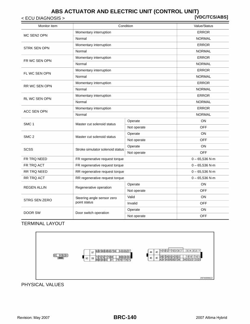
[VDC/TCS/ABS]ABS ACTUATOR AND ELECTRIC UNIT (CONTROL UNIT)
< ECU DIAGNOSIS >
TERMINAL LAYOUT
PHYSICAL VALUES
MC SEN2 OPNMomentary interruption ERROR
Normal NORMAL
STRK SEN OPNMomentary interruption ERROR
Normal NORMAL
FR WC SEN OPNMomentary interruption ERROR
Normal NORMAL
FL WC SEN OPNMomentary interruption ERROR
Normal NORMAL
RR WC SEN OPNMomentary interruption ERROR
Normal NORMAL
RL WC SEN OPNMomentary interruption ERROR
Normal NORMAL
ACC SEN OPNMomentary interruption ERROR
Normal NORMAL
SMC 1 Master cut solenoid statusOperate ON
Not operate OFF
SMC 2 Master cut solenoid statusOperate ON
Not operate OFF
SCSS Stroke simulator solenoid statusOperate ON
Not operate OFF
FR TRQ NEED FR regenerative request torque 0 – 65,536 N·m
FR TRQ ACT FR regenerative request torque 0 – 65,536 N·m
RR TRQ NEED RR regenerative request torque 0 – 65,536 N·m
RR TRQ ACT RR regenerative request torque 0 – 65,536 N·m
REGEN ALLIN Regenerative operationOperate ON
Not operate OFF
STRG SEN ZEROSteering angle sensor zero point status
Valid ON
Invalid OFF
DOOR SW Door switch operationOperate ON
Not operate OFF
Monitor item Condition Value/Status
JSFIA0066ZZ
BRC-140
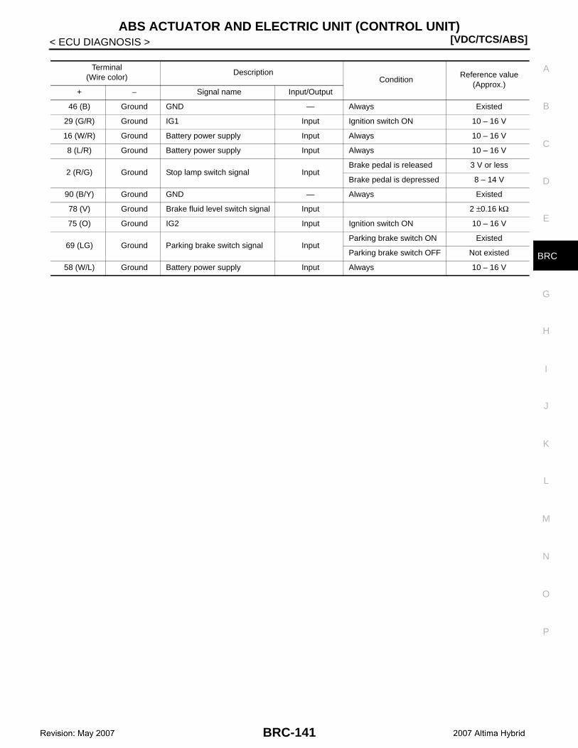
ABS ACTUATOR AND ELECTRIC UNIT (CONTROL UNIT)[VDC/TCS/ABS]
C
D
E
G
H
I
J
K
L
M
A
B
RC
N
O
P
< ECU DIAGNOSIS >
B
Terminal(Wire color)
DescriptionCondition
Reference value(Approx.)
+ − Signal name Input/Output
46 (B) Ground GND — Always Existed
29 (G/R) Ground IG1 Input Ignition switch ON 10 – 16 V
16 (W/R) Ground Battery power supply Input Always 10 – 16 V
8 (L/R) Ground Battery power supply Input Always 10 – 16 V
2 (R/G) Ground Stop lamp switch signal InputBrake pedal is released 3 V or less
Brake pedal is depressed 8 – 14 V
90 (B/Y) Ground GND — Always Existed
78 (V) Ground Brake fluid level switch signal Input 2 ±0.16 kΩ
75 (O) Ground IG2 Input Ignition switch ON 10 – 16 V
69 (LG) Ground Parking brake switch signal InputParking brake switch ON Existed
Parking brake switch OFF Not existed
58 (W/L) Ground Battery power supply Input Always 10 – 16 V
BRC-141
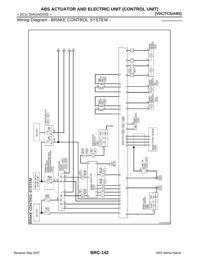
[VDC/TCS/ABS]ABS ACTUATOR AND ELECTRIC UNIT (CONTROL UNIT)
< ECU DIAGNOSIS >
Wiring Diagram - BRAKE CONTROL SYSTEM - INFOID:0000000001501976
ALFWA0005GB
BRC-142
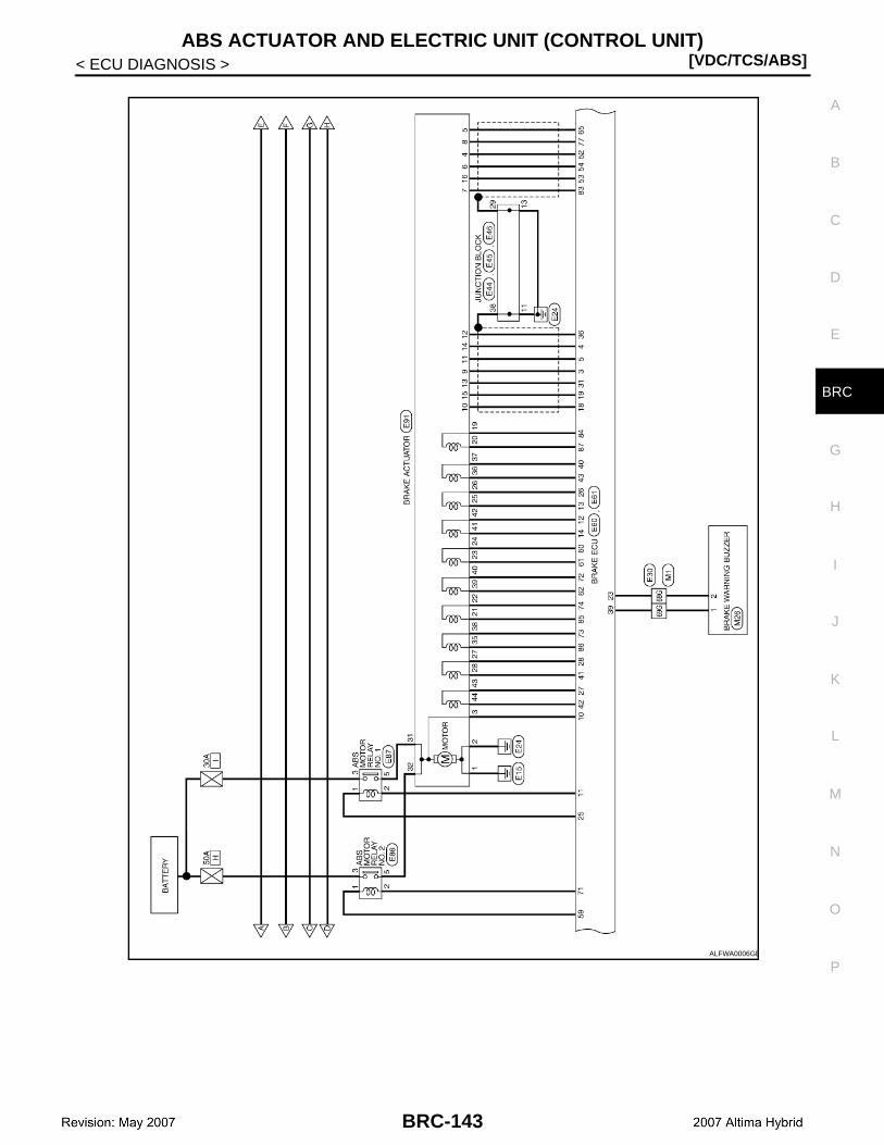
ABS ACTUATOR AND ELECTRIC UNIT (CONTROL UNIT)[VDC/TCS/ABS]
C
D
E
G
H
I
J
K
L
M
A
B
RC
N
O
P
< ECU DIAGNOSIS >
B
ALFWA0006GB
BRC-143

[VDC/TCS/ABS]ABS ACTUATOR AND ELECTRIC UNIT (CONTROL UNIT)
< ECU DIAGNOSIS >
ALFWA0007GB
BRC-144

ABS ACTUATOR AND ELECTRIC UNIT (CONTROL UNIT)[VDC/TCS/ABS]
C
D
E
G
H
I
J
K
L
M
A
B
RC
N
O
P
< ECU DIAGNOSIS >
B
ALFIA0056GB
BRC-145
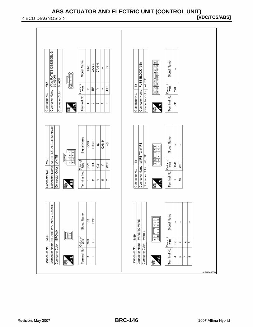
[VDC/TCS/ABS]ABS ACTUATOR AND ELECTRIC UNIT (CONTROL UNIT)
< ECU DIAGNOSIS >
ALFIA0057GB
BRC-146
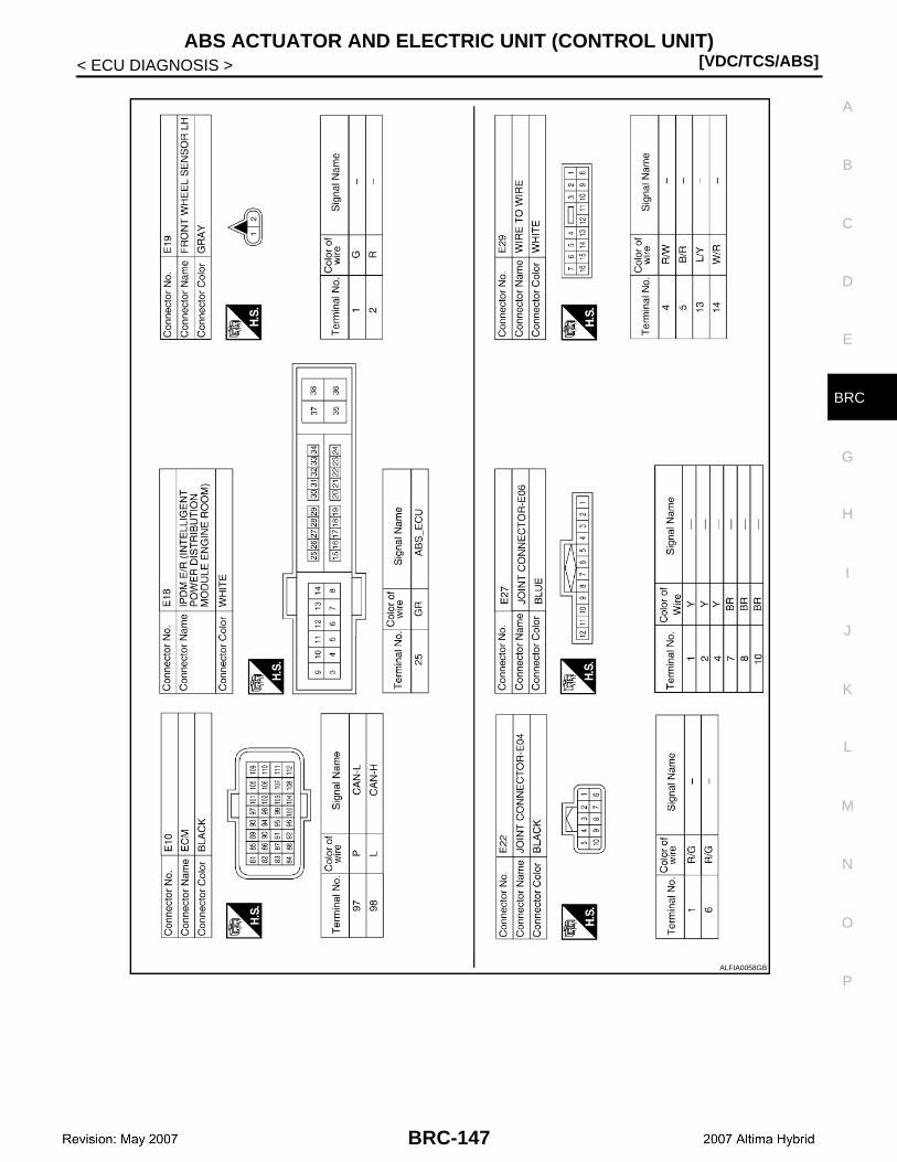
ABS ACTUATOR AND ELECTRIC UNIT (CONTROL UNIT)[VDC/TCS/ABS]
C
D
E
G
H
I
J
K
L
M
A
B
RC
N
O
P
< ECU DIAGNOSIS >
B
ALFIA0058GB
BRC-147
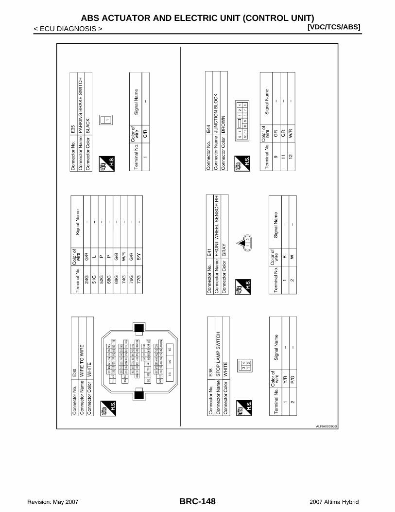
[VDC/TCS/ABS]ABS ACTUATOR AND ELECTRIC UNIT (CONTROL UNIT)
< ECU DIAGNOSIS >
ALFIA0059GB
BRC-148

ABS ACTUATOR AND ELECTRIC UNIT (CONTROL UNIT)[VDC/TCS/ABS]
C
D
E
G
H
I
J
K
L
M
A
B
RC
N
O
P
< ECU DIAGNOSIS >
B
ALFIA0060GB
BRC-149
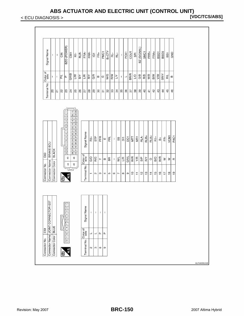
[VDC/TCS/ABS]ABS ACTUATOR AND ELECTRIC UNIT (CONTROL UNIT)
< ECU DIAGNOSIS >
ALFIA0061GB
BRC-150

ABS ACTUATOR AND ELECTRIC UNIT (CONTROL UNIT)[VDC/TCS/ABS]
C
D
E
G
H
I
J
K
L
M
A
B
RC
N
O
P
< ECU DIAGNOSIS >
B
ALFIA0062GB
BRC-151
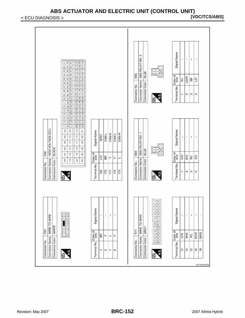
[VDC/TCS/ABS]ABS ACTUATOR AND ELECTRIC UNIT (CONTROL UNIT)
< ECU DIAGNOSIS >
ALFIA0063GB
BRC-152

ABS ACTUATOR AND ELECTRIC UNIT (CONTROL UNIT)[VDC/TCS/ABS]
C
D
E
G
H
I
J
K
L
M
A
B
RC
N
O
P
< ECU DIAGNOSIS >
B
ALFIA0064GB
BRC-153
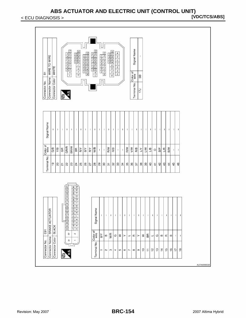
[VDC/TCS/ABS]ABS ACTUATOR AND ELECTRIC UNIT (CONTROL UNIT)
< ECU DIAGNOSIS >
ALFIA0065GB
BRC-154
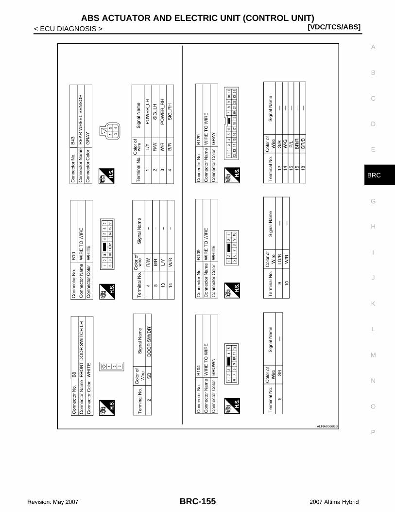
ABS ACTUATOR AND ELECTRIC UNIT (CONTROL UNIT)[VDC/TCS/ABS]
C
D
E
G
H
I
J
K
L
M
A
B
RC
N
O
P
< ECU DIAGNOSIS >
B
ALFIA0066GB
BRC-155
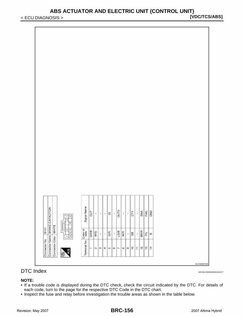
[VDC/TCS/ABS]ABS ACTUATOR AND ELECTRIC UNIT (CONTROL UNIT)
< ECU DIAGNOSIS >
DTC Index INFOID:0000000001501977
NOTE:• If a trouble code is displayed during the DTC check, check the circuit indicated by the DTC. For details of
each code, turn to the page for the respective DTC Code in the DTC chart.• Inspect the fuse and relay before investigation the trouble areas as shown in the table below.
ALFIA0067GB
BRC-156
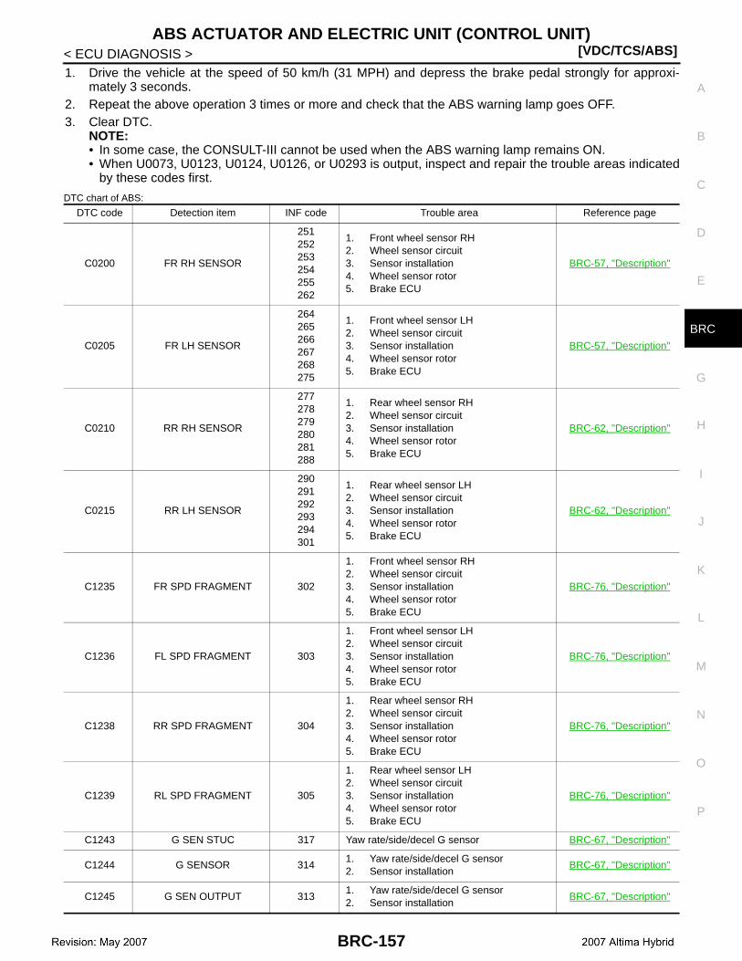
ABS ACTUATOR AND ELECTRIC UNIT (CONTROL UNIT)[VDC/TCS/ABS]
C
D
E
G
H
I
J
K
L
M
A
B
RC
N
O
P
< ECU DIAGNOSIS >
B
1. Drive the vehicle at the speed of 50 km/h (31 MPH) and depress the brake pedal strongly for approxi-mately 3 seconds.
2. Repeat the above operation 3 times or more and check that the ABS warning lamp goes OFF.3. Clear DTC.
NOTE:• In some case, the CONSULT-III cannot be used when the ABS warning lamp remains ON.• When U0073, U0123, U0124, U0126, or U0293 is output, inspect and repair the trouble areas indicated
by these codes first.
DTC chart of ABS:
DTC code Detection item INF code Trouble area Reference page
C0200 FR RH SENSOR
251252253254255262
1. Front wheel sensor RH2. Wheel sensor circuit3. Sensor installation4. Wheel sensor rotor5. Brake ECU
BRC-57, "Description"
C0205 FR LH SENSOR
264265266267268275
1. Front wheel sensor LH2. Wheel sensor circuit3. Sensor installation4. Wheel sensor rotor5. Brake ECU
BRC-57, "Description"
C0210 RR RH SENSOR
277278279280281288
1. Rear wheel sensor RH2. Wheel sensor circuit3. Sensor installation4. Wheel sensor rotor5. Brake ECU
BRC-62, "Description"
C0215 RR LH SENSOR
290291292293294301
1. Rear wheel sensor LH2. Wheel sensor circuit3. Sensor installation4. Wheel sensor rotor5. Brake ECU
BRC-62, "Description"
C1235 FR SPD FRAGMENT 302
1. Front wheel sensor RH2. Wheel sensor circuit3. Sensor installation4. Wheel sensor rotor5. Brake ECU
BRC-76, "Description"
C1236 FL SPD FRAGMENT 303
1. Front wheel sensor LH2. Wheel sensor circuit3. Sensor installation4. Wheel sensor rotor5. Brake ECU
BRC-76, "Description"
C1238 RR SPD FRAGMENT 304
1. Rear wheel sensor RH2. Wheel sensor circuit3. Sensor installation4. Wheel sensor rotor5. Brake ECU
BRC-76, "Description"
C1239 RL SPD FRAGMENT 305
1. Rear wheel sensor LH2. Wheel sensor circuit3. Sensor installation4. Wheel sensor rotor5. Brake ECU
BRC-76, "Description"
C1243 G SEN STUC 317 Yaw rate/side/decel G sensor BRC-67, "Description"
C1244 G SENSOR 3141. Yaw rate/side/decel G sensor2. Sensor installation
BRC-67, "Description"
C1245 G SEN OUTPUT 3131. Yaw rate/side/decel G sensor2. Sensor installation
BRC-67, "Description"
BRC-157
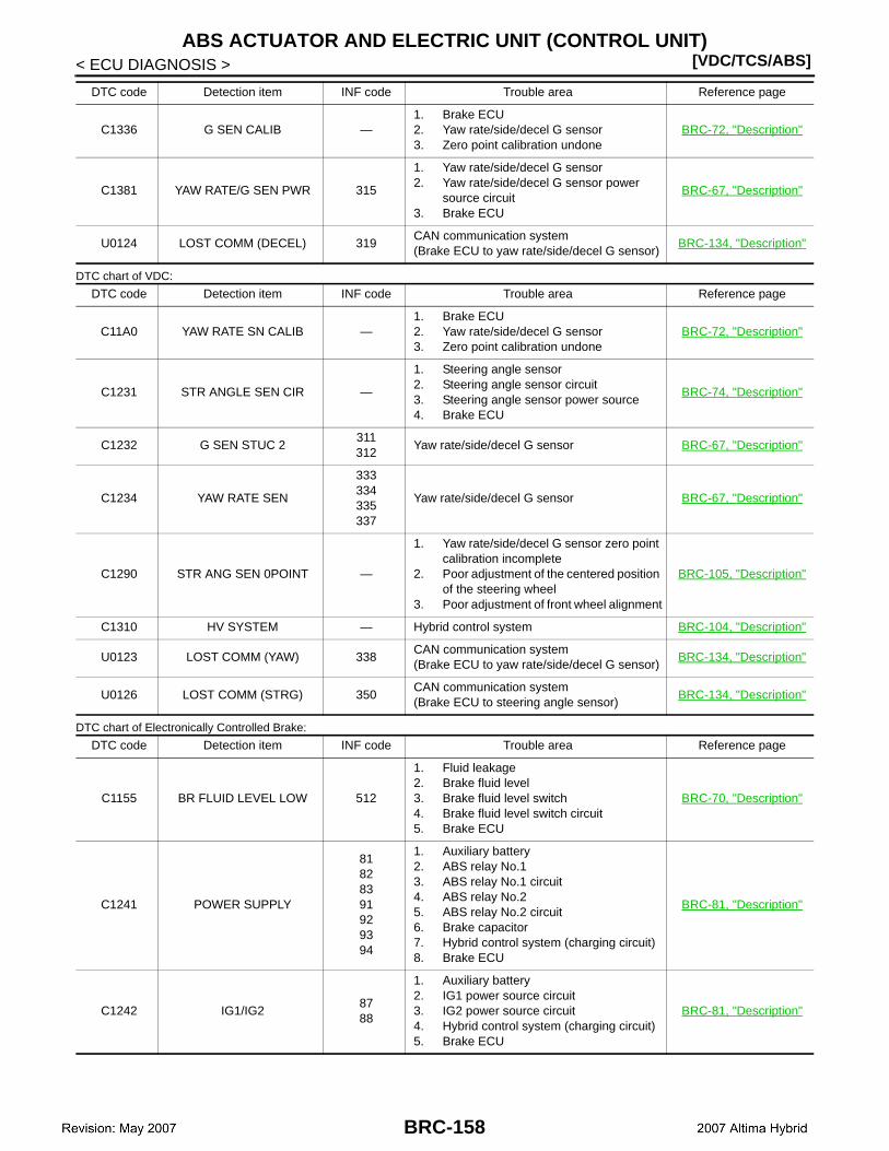
[VDC/TCS/ABS]ABS ACTUATOR AND ELECTRIC UNIT (CONTROL UNIT)
< ECU DIAGNOSIS >
DTC chart of VDC:
DTC chart of Electronically Controlled Brake:
C1336 G SEN CALIB —1. Brake ECU2. Yaw rate/side/decel G sensor3. Zero point calibration undone
BRC-72, "Description"
C1381 YAW RATE/G SEN PWR 315
1. Yaw rate/side/decel G sensor2. Yaw rate/side/decel G sensor power
source circuit3. Brake ECU
BRC-67, "Description"
U0124 LOST COMM (DECEL) 319CAN communication system(Brake ECU to yaw rate/side/decel G sensor)
BRC-134, "Description"
DTC code Detection item INF code Trouble area Reference page
C11A0 YAW RATE SN CALIB —1. Brake ECU2. Yaw rate/side/decel G sensor3. Zero point calibration undone
BRC-72, "Description"
C1231 STR ANGLE SEN CIR —
1. Steering angle sensor2. Steering angle sensor circuit3. Steering angle sensor power source4. Brake ECU
BRC-74, "Description"
C1232 G SEN STUC 2311312
Yaw rate/side/decel G sensor BRC-67, "Description"
C1234 YAW RATE SEN
333334335337
Yaw rate/side/decel G sensor BRC-67, "Description"
C1290 STR ANG SEN 0POINT —
1. Yaw rate/side/decel G sensor zero point calibration incomplete
2. Poor adjustment of the centered position of the steering wheel
3. Poor adjustment of front wheel alignment
BRC-105, "Description"
C1310 HV SYSTEM — Hybrid control system BRC-104, "Description"
U0123 LOST COMM (YAW) 338CAN communication system(Brake ECU to yaw rate/side/decel G sensor)
BRC-134, "Description"
U0126 LOST COMM (STRG) 350CAN communication system(Brake ECU to steering angle sensor)
BRC-134, "Description"
DTC code Detection item INF code Trouble area Reference page
C1155 BR FLUID LEVEL LOW 512
1. Fluid leakage2. Brake fluid level3. Brake fluid level switch4. Brake fluid level switch circuit5. Brake ECU
BRC-70, "Description"
C1241 POWER SUPPLY
81828391929394
1. Auxiliary battery2. ABS relay No.13. ABS relay No.1 circuit4. ABS relay No.25. ABS relay No.2 circuit6. Brake capacitor7. Hybrid control system (charging circuit)8. Brake ECU
BRC-81, "Description"
C1242 IG1/IG28788
1. Auxiliary battery2. IG1 power source circuit3. IG2 power source circuit4. Hybrid control system (charging circuit)5. Brake ECU
BRC-81, "Description"
DTC code Detection item INF code Trouble area Reference page
BRC-158
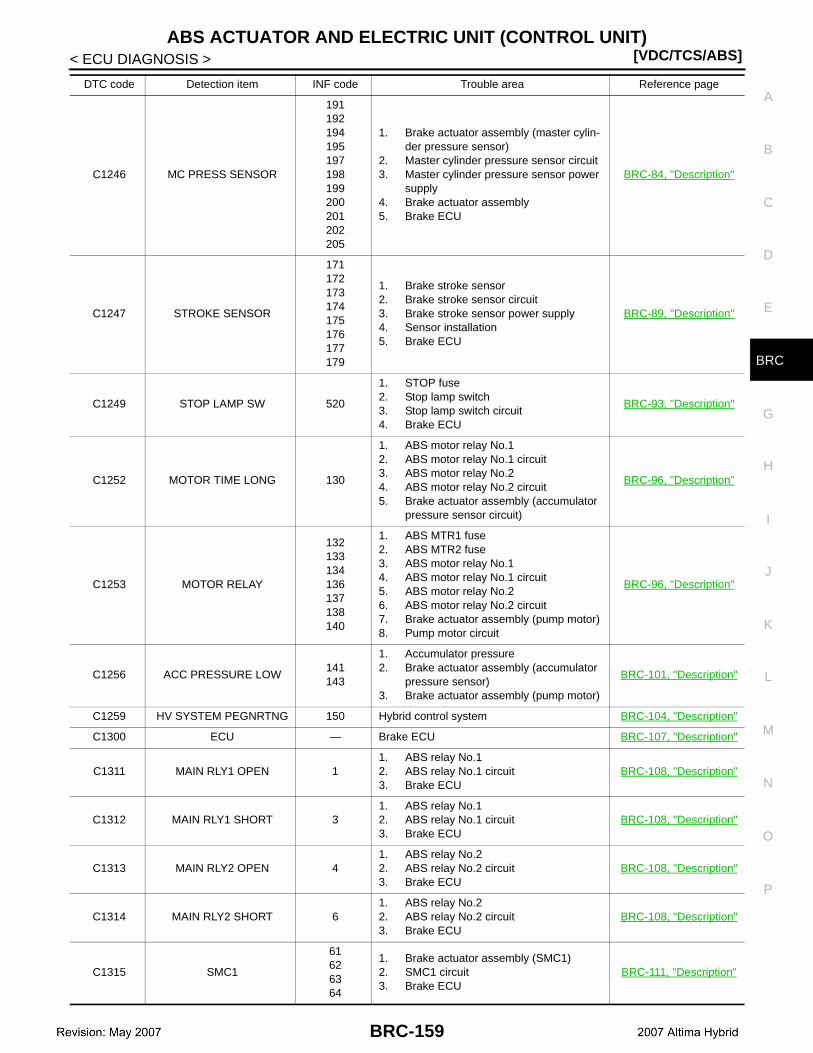
ABS ACTUATOR AND ELECTRIC UNIT (CONTROL UNIT)[VDC/TCS/ABS]
C
D
E
G
H
I
J
K
L
M
A
B
RC
N
O
P
< ECU DIAGNOSIS >
B
C1246 MC PRESS SENSOR
191192194195197198199200201202205
1. Brake actuator assembly (master cylin-der pressure sensor)
2. Master cylinder pressure sensor circuit3. Master cylinder pressure sensor power
supply4. Brake actuator assembly5. Brake ECU
BRC-84, "Description"
C1247 STROKE SENSOR
171172173174175176177179
1. Brake stroke sensor2. Brake stroke sensor circuit3. Brake stroke sensor power supply4. Sensor installation5. Brake ECU
BRC-89, "Description"
C1249 STOP LAMP SW 520
1. STOP fuse2. Stop lamp switch3. Stop lamp switch circuit4. Brake ECU
BRC-93, "Description"
C1252 MOTOR TIME LONG 130
1. ABS motor relay No.12. ABS motor relay No.1 circuit3. ABS motor relay No.24. ABS motor relay No.2 circuit5. Brake actuator assembly (accumulator
pressure sensor circuit)
BRC-96, "Description"
C1253 MOTOR RELAY
132133134136137138140
1. ABS MTR1 fuse2. ABS MTR2 fuse3. ABS motor relay No.14. ABS motor relay No.1 circuit5. ABS motor relay No.26. ABS motor relay No.2 circuit7. Brake actuator assembly (pump motor)8. Pump motor circuit
BRC-96, "Description"
C1256 ACC PRESSURE LOW141143
1. Accumulator pressure2. Brake actuator assembly (accumulator
pressure sensor)3. Brake actuator assembly (pump motor)
BRC-101, "Description"
C1259 HV SYSTEM PEGNRTNG 150 Hybrid control system BRC-104, "Description"
C1300 ECU — Brake ECU BRC-107, "Description"
C1311 MAIN RLY1 OPEN 11. ABS relay No.12. ABS relay No.1 circuit3. Brake ECU
BRC-108, "Description"
C1312 MAIN RLY1 SHORT 31. ABS relay No.12. ABS relay No.1 circuit3. Brake ECU
BRC-108, "Description"
C1313 MAIN RLY2 OPEN 41. ABS relay No.22. ABS relay No.2 circuit3. Brake ECU
BRC-108, "Description"
C1314 MAIN RLY2 SHORT 61. ABS relay No.22. ABS relay No.2 circuit3. Brake ECU
BRC-108, "Description"
C1315 SMC1
61626364
1. Brake actuator assembly (SMC1)2. SMC1 circuit3. Brake ECU
BRC-111, "Description"
DTC code Detection item INF code Trouble area Reference page
BRC-159

[VDC/TCS/ABS]ABS ACTUATOR AND ELECTRIC UNIT (CONTROL UNIT)
< ECU DIAGNOSIS >
C1316 SMC2
66676869
1. Brake actuator assembly (SMC2)2. SMC2 circuit3. Brake ECU
BRC-111, "Description"
C1319 SCSS
71727374
1. Brake simulator2. Brake simulator circuit3. Brake ECU
BRC-116, "Description"
C1341 FR RH HYDRAULIC
551552553554555
1. Fluid leakage2. Disc rotor3. Brake actuator assembly
BRC-118, "Description"
C1342 FR LH HYDRAULIC
561562563564565
1. Fluid leakage2. Disc rotor3. Brake actuator assembly
BRC-118, "Description"
C1343 RR RH HYDRAULIC
571572573574575
1. Fluid leakage2. Disc rotor3. Brake actuator assembly
BRC-118, "Description"
C1344 RR LH HYDRAULIC
581582583584585
1. Fluid leakage2. Disc rotor3. Brake actuator assembly
BRC-118, "Description"
C1345 LINEAR VLV CALIB —1. Initialization of linear solenoid valve and
calibration undone2. Brake ECU
BRC-122, "Description"
C1352 SLA FR SOL
11121314
1. Brake actuator assembly (SLAFR)2. SLAFR circuit3. Brake ECU
BRC-111, "Description"
C1353 SLA FL SOL
21222324
1. Brake actuator assembly (SLAFL)2. SLAFL circuit3. Brake ECU
BRC-111, "Description"
C1354 SLA RR SOL
31323334
1. Brake actuator assembly (SLARR)2. SLARR circuit3. Brake ECU
BRC-111, "Description"
C1355 SLA RL SOL
41424344
1. Brake actuator assembly (SLARL)2. SLARL circuit3. Brake ECU
BRC-111, "Description"
C1356 SLR FR SOL
16171819
1. Brake actuator assembly (SLRFR)2. SLRFR circuit3. Brake ECU
BRC-111, "Description"
C1357 SLR FL SOL
26272829
1. Brake actuator assembly (SLRFL)2. SLRFL circuit3. Brake ECU
BRC-111, "Description"
C1358 SLR RR SOL
36373839
1. Brake actuator assembly (SLRRR)2. SLRRR circuit3. Brake ECU
BRC-111, "Description"
DTC code Detection item INF code Trouble area Reference page
BRC-160
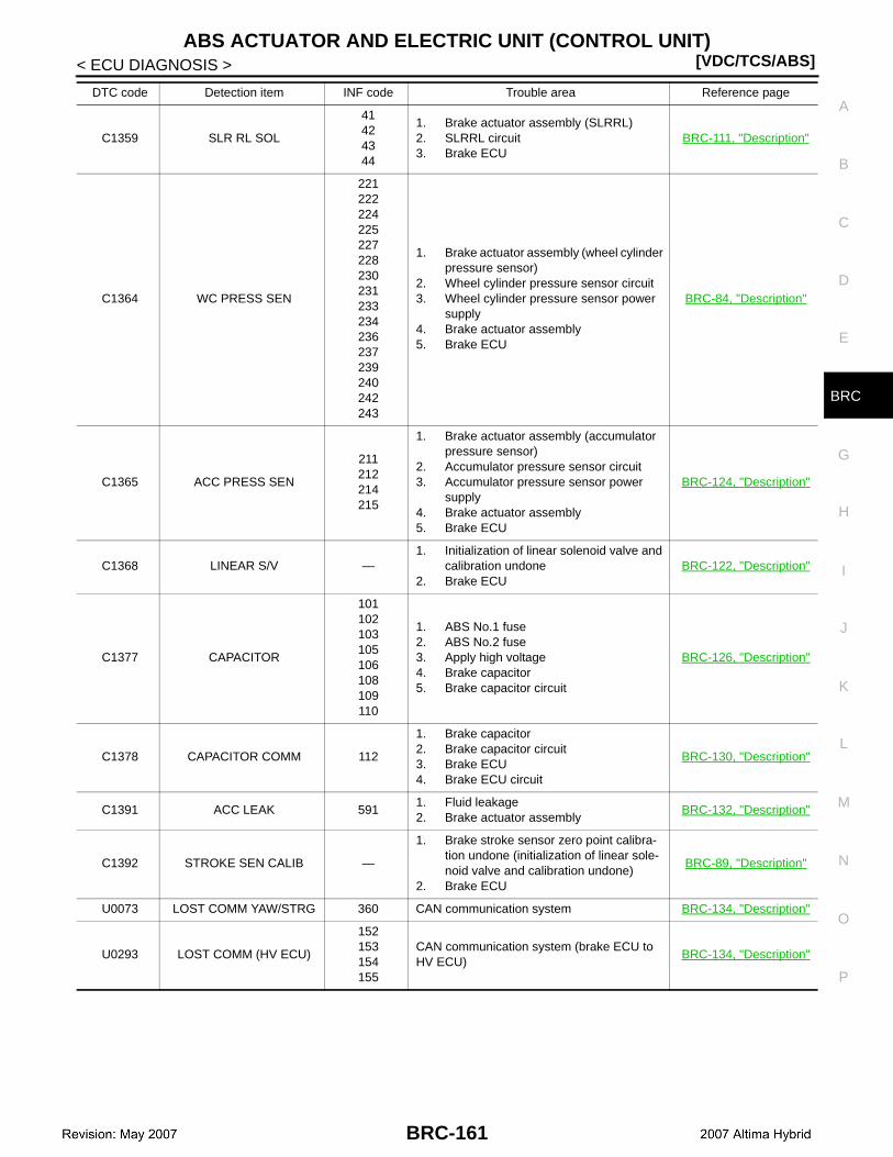
ABS ACTUATOR AND ELECTRIC UNIT (CONTROL UNIT)[VDC/TCS/ABS]
C
D
E
G
H
I
J
K
L
M
A
B
RC
N
O
P
< ECU DIAGNOSIS >
B
C1359 SLR RL SOL
41424344
1. Brake actuator assembly (SLRRL)2. SLRRL circuit3. Brake ECU
BRC-111, "Description"
C1364 WC PRESS SEN
221222224225227228230231233234236237239240242243
1. Brake actuator assembly (wheel cylinder pressure sensor)
2. Wheel cylinder pressure sensor circuit3. Wheel cylinder pressure sensor power
supply4. Brake actuator assembly5. Brake ECU
BRC-84, "Description"
C1365 ACC PRESS SEN
211212214215
1. Brake actuator assembly (accumulator pressure sensor)
2. Accumulator pressure sensor circuit3. Accumulator pressure sensor power
supply4. Brake actuator assembly5. Brake ECU
BRC-124, "Description"
C1368 LINEAR S/V —1. Initialization of linear solenoid valve and
calibration undone2. Brake ECU
BRC-122, "Description"
C1377 CAPACITOR
101102103105106108109110
1. ABS No.1 fuse2. ABS No.2 fuse3. Apply high voltage4. Brake capacitor5. Brake capacitor circuit
BRC-126, "Description"
C1378 CAPACITOR COMM 112
1. Brake capacitor2. Brake capacitor circuit3. Brake ECU4. Brake ECU circuit
BRC-130, "Description"
C1391 ACC LEAK 5911. Fluid leakage2. Brake actuator assembly
BRC-132, "Description"
C1392 STROKE SEN CALIB —
1. Brake stroke sensor zero point calibra-tion undone (initialization of linear sole-noid valve and calibration undone)
2. Brake ECU
BRC-89, "Description"
U0073 LOST COMM YAW/STRG 360 CAN communication system BRC-134, "Description"
U0293 LOST COMM (HV ECU)
152153154155
CAN communication system (brake ECU to HV ECU)
BRC-134, "Description"
DTC code Detection item INF code Trouble area Reference page
BRC-161

[VDC/TCS/ABS]ABS ACTUATOR AND ELECTRIC UNIT (CONTROL UNIT)
< ECU DIAGNOSIS >TEST MODE DTC of ABS:
TEST MODE DTC of VDC:
TEST MODE DTC of Electronically controlled Brake:
DTC code Detection item INF code Trouble area Reference page
C1271 FR SPD OUTPUT —1. Front wheel sensor RH2. Snesor installation3. Wheel sensor rotor
BRC-57, "Description"
C1272 FL SPD OUTPUT —1. Front wheel sensor LH2. Snesor installation3. Wheel sensor rotor
BRC-57, "Description"
C1273 RR SPD OUTPUT —1. Rear wheel sensor RH2. Snesor installation3. Wheel sensor rotor
BRC-62, "Description"
C1274 RL SPD OUTPUT —1. Rear wheel sensor LH2. Snesor installation3. Wheel sensor rotor
BRC-62, "Description"
C1275 FR SPD OUTPUT HI — Wheel sensor rotor BRC-76, "Description"
C1276 FL SPD OUTPUT HI — Wheel sensor rotor BRC-76, "Description"
C1277 RR SPD OUTPUT HI — Wheel sensor rotor BRC-76, "Description"
C1278 RL SPD OUTPUT HI — Wheel sensor rotor BRC-76, "Description"
C1279 G SEN OUTPUT —1. Yaw rate/side/decel G sensor2. Sensor installation
BRC-67, "Description"
C1281 MC SENSOR OUTPUT —1. Stop lamp switch2. Master cylinder pressure sensor
BRC-67, "Description"
DTC code Detection item INF code Trouble area Reference page
C0371 YAW SEN OUTPUT — Yaw rate/side/decel G sensor BRC-67, "Description"
DTC code Detection item INF code Trouble area Reference page
C1346 STROKE SEN CALIB — Brake stroke sensor BRC-89, "Description"
BRC-162
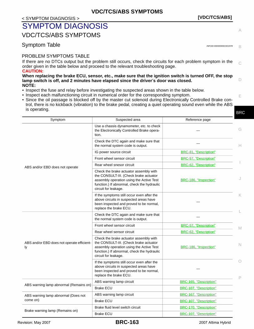
VDC/TCS/ABS SYMPTOMS[VDC/TCS/ABS]
C
D
E
G
H
I
J
K
L
M
A
B
RC
N
O
P
< SYMPTOM DIAGNOSIS >
B
SYMPTOM DIAGNOSISVDC/TCS/ABS SYMPTOMS
Symptom Table INFOID:0000000001501978
PROBLEM SYMPTOMS TABLEIf there are no DTCs output but the problem still occurs, check the circuits for each problem symptom in theorder given in the table below and proceed to the relevant troubleshooting page.CAUTION:When replacing the brake ECU, sensor, etc., make sure that the ignition switch is turned OFF, the stoplamp switch is off, and 2 minutes have elapsed since the driver′s door was closed.NOTE:• Inspect the fuse and relay before investigating the suspected areas shown in the table below.• Inspect each malfunctioning circuit in numerical order for the corresponding symptom.• Since the oil passage is blocked off by the master cut solenoid during Electronically Controlled Brake con-
trol, there is no kickback (vibration) to the brake pedal, creating a quiet operating sound even while the ABSis operating.
Symptom Suspected area Reference page
ABS and/or EBD does not operate
Use a chassis dynamometer, etc. to check the Electronically Controlled Brake opera-tion.
—
Check the DTC again and make sure that the normal system code is output.
—
IG power source circuit BRC-81, "Description"
Front wheel sensor circuit BRC-57, "Description"
Rear wheel snesor circuit BRC-62, "Description"
Check the brake actuator assembly with the CONSULT-III. (Check brake actuator assembly operation using the Active Test function.) If abnormal, check the hydraulic circuit for leakage.
BRC-186, "Inspection"
If the symptoms still occur even after the above circuits in suspected areas have been inspected and proved to be normal, replace the brake ECU.
—
ABS and/or EBD does not operate efficient-ly
Check the DTC again and make sure that the normal system code is output.
—
Front wheel sensor circuit BRC-57, "Description"
Rear wheel sensor circuit BRC-62, "Description"
Check the brake actuator assembly with the CONSULT-III. (Check brake actuator assembly operation using the Active Test function.) If abnormal, check the hydraulic circuit for leakage.
BRC-186, "Inspection"
If the symptoms still occur even after the above circuits in suspected areas have been inspected and proved to be normal, replace the brake ECU.
—
ABS warning lamp abnormal (Remains on)ABS warning lamp circuit BRC-165, "Description"
Brake ECU BRC-107, "Description"
ABS warning lamp abnormal (Does not come on)
ABS warning lamp circuit BRC-167, "Description"
Brake ECU BRC-107, "Description"
Brake warning lamp (Remains on)Brake fluid level switch circuit BRC-170, "Description"
Brake ECU BRC-107, "Description"
BRC-163
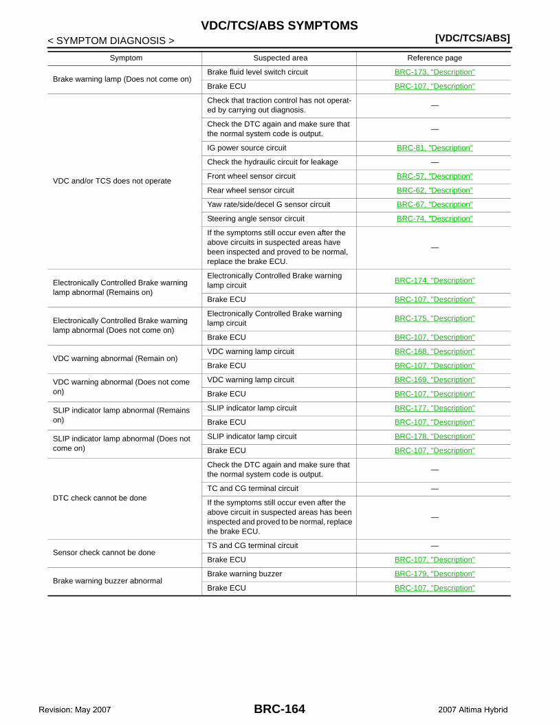
[VDC/TCS/ABS]VDC/TCS/ABS SYMPTOMS
< SYMPTOM DIAGNOSIS >
Brake warning lamp (Does not come on)Brake fluid level switch circuit BRC-173, "Description"
Brake ECU BRC-107, "Description"
VDC and/or TCS does not operate
Check that traction control has not operat-ed by carrying out diagnosis.
—
Check the DTC again and make sure that the normal system code is output.
—
IG power source circuit BRC-81, "Description"
Check the hydraulic circuit for leakage —
Front wheel sensor circuit BRC-57, "Description"
Rear wheel sensor circuit BRC-62, "Description"
Yaw rate/side/decel G sensor circuit BRC-67, "Description"
Steering angle sensor circuit BRC-74, "Description"
If the symptoms still occur even after the above circuits in suspected areas have been inspected and proved to be normal, replace the brake ECU.
—
Electronically Controlled Brake warning lamp abnormal (Remains on)
Electronically Controlled Brake warning lamp circuit
BRC-174, "Description"
Brake ECU BRC-107, "Description"
Electronically Controlled Brake warning lamp abnormal (Does not come on)
Electronically Controlled Brake warning lamp circuit
BRC-175, "Description"
Brake ECU BRC-107, "Description"
VDC warning abnormal (Remain on)VDC warning lamp circuit BRC-168, "Description"
Brake ECU BRC-107, "Description"
VDC warning abnormal (Does not come on)
VDC warning lamp circuit BRC-169, "Description"
Brake ECU BRC-107, "Description"
SLIP indicator lamp abnormal (Remains on)
SLIP indicator lamp circuit BRC-177, "Description"
Brake ECU BRC-107, "Description"
SLIP indicator lamp abnormal (Does not come on)
SLIP indicator lamp circuit BRC-178, "Description"
Brake ECU BRC-107, "Description"
DTC check cannot be done
Check the DTC again and make sure that the normal system code is output.
—
TC and CG terminal circuit —
If the symptoms still occur even after the above circuit in suspected areas has been inspected and proved to be normal, replace the brake ECU.
—
Sensor check cannot be doneTS and CG terminal circuit —
Brake ECU BRC-107, "Description"
Brake warning buzzer abnormalBrake warning buzzer BRC-179, "Description"
Brake ECU BRC-107, "Description"
Symptom Suspected area Reference page
BRC-164

ABS WARNING LAMP REMAINS ON[VDC/TCS/ABS]
C
D
E
G
H
I
J
K
L
M
A
B
RC
N
O
P
< SYMPTOM DIAGNOSIS >
B
ABS WARNING LAMP REMAINS ON
Description INFOID:0000000001501979
The brake ECU is connected to the combination meter with CAN communication via HV ECU. If any of the fol-lowing is detected, the ABS warning lamp remains on.• The brake ECU connectors are disconnected from the brake ECU.• There is a malfunction in the brake ECU internal circuit or in the HV ECU.• There is an open in the harness between the combination meter, HV ECU and the brake ECU.NOTE:In some cases, the CONSULT-III cannot be used when the brake ECU is abnormal.
Diagnosis Procedure INFOID:0000000001501980
NOTE:If a malfunction was detected in wheel sensor during the last travel, ABS warning lamp may remains ON untilthe wheel sensor can be checked that it is normal at 10 km/h (6 MPH) during the next travel.CAUTION:When replacing the brake ECU, perform initialization of linear solenoid valve and calibration.
1.CHECK CAN COMMUNICATION SYSTEM
Check if the CAN communication system DTC is output.
Result
A >> GO TO 2.B >> Inspect CAN communication system.
2.CHECK IF BRAKE ECU CONNECTOR IS SECURELY CONNECTED
Check if the brake ECU connector is securely connected.NOTE:The connector should be securely connected.Is the inspection result normal?YES >> GO TO 3.NO >> Connect connector to ECU correctly.
3.CHECK AUXILIARY BATTERY
Check the auxiliary battery voltage.
Is the inspection result normal?YES >> GO TO 4.NO >> Charge or replace auxiliary battery.
4.INSPECT BRAKE ECU (IG1 TERMINAL)
1. Disconnect the brake ECU connector.2. Turn the ignition switch ON.3. Measure the voltage according to the value(s) in the table below.
Is the inspection result normal?YES >> GO TO 5.
Condition Proceed to
DTC is not output. A
DTC is output. B
Standard voltage : 11 to 14 V
Brake ECUCondition Specified condition
Connector Terminal
E60 29 – Ground Ignition switch ON 10 to 14 V
BRC-165

[VDC/TCS/ABS]ABS WARNING LAMP REMAINS ON
< SYMPTOM DIAGNOSIS >NO >> Repair or replace harness or connector (IG1 circuit).
5.INSPECT BRAKE ECU (GND TERMINAL)
1. Turn the ignition switch OFF.2. Disconnect the brake ECU connectors.3. Measure the resistance according to the value(s) in the table below.
Is the inspection result normal?YES >> GO TO 6.NO >> Repair or replace harness or connector (GND circuit).
6.INSPECT HV ECU
Perform HV ECU self-diagnosis.Is the inspection result normal?YES >> Repair or replace malfunctioning components.NO >> GO TO 7.
7.INSPECT COMBINATION METER ASSEMBLY
1. Reconnect the brake ECU connectors.2. Perform “ABS WARN LAMP” of the combination meter (meter CPU) using the “ACTIVE TEST”.
NOTE:• The ABS warning lamp turns ON or OFF in accordance with the CONSULT-III.• If troubleshooting has been carried out according to the Problem Symptoms Table, refer back to the
table and proceed to the next step before replacing part.Is the inspection result normal?YES >> Replace brake ECU.NO >> Replace combination meter assembly.
Brake ECUCondition Specified condition
Connector Terminal
E60 46 – Ground Always Below 1 Ω
E61 90 – Ground Always Below 1 Ω
BRC-166

ABS WARNING LAMP DOES NOT COME ON[VDC/TCS/ABS]
C
D
E
G
H
I
J
K
L
M
A
B
RC
N
O
P
< SYMPTOM DIAGNOSIS >
B
ABS WARNING LAMP DOES NOT COME ON
Description INFOID:0000000001501981
The brake ECU is connected to the combination meter with CAN communication via HV ECU.
Diagnosis Procedure INFOID:0000000001501982
CAUTION:When replacing the brake ECU, perform initialization of linear solenoid valve and calibration.
1.CHECK CAN COMMUNICATION SYSTEM
Check if the CAN communication system DTC is output.
Result
A >> GO TO 2.B >> Inspect CAN communication system.
2.INSPECT HV ECU
Perform HV ECU self-diagnosis.Is the inspection result normal?YES >> Repair or replace malfunctioning components.NO >> GO TO 3.
3.CHECK ABS WARNING LAMP
1. Disconnect the brake ECU connector.2. Turn the ignition switch ON.3. Check that the ABS warning lamp come ON.
NOTE:• The ABS warning lamp comes ON.• If troubleshooting has been carried out according to the Problem Symptoms Table, refer back to the
table and proceed to the next step before replacing the part.Is the inspection result normal?YES >> Replace brake ECU.NO >> GO TO 4.
4.INSPECT COMBINATION METER ASSEMBLY
1. Turn the ignition switch OFF.2. Reconnect the brake ECU connector.3. Perform “ABS WARN LAMP” of the combination meter (meter CPU) using the “ACTIVE TEST”.
NOTE:• The ABS warning lamp turns ON or OFF in accordance with the CONSULT-III.• If troubleshooting has been carried out according to the Problem Symptoms Table, refer back to the
table and proceed to the next step.Is the inspection result normal?YES >> Replace brake ECU.NO >> Replace combination meter assembly.
Condition Proceed to
DTC is not output. A
DTC is output. B
BRC-167
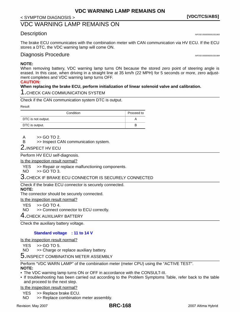
[VDC/TCS/ABS]VDC WARNING LAMP REMAINS ON
< SYMPTOM DIAGNOSIS >
VDC WARNING LAMP REMAINS ON
Description INFOID:0000000001501983
The brake ECU communicates with the combination meter with CAN communication via HV ECU. If the ECUstores a DTC, the VDC warning lamp will come ON.
Diagnosis Procedure INFOID:0000000001501984
NOTE:When removing battery, VDC warning lamp turns ON because the stored zero point of steering angle iserased. In this case, when driving in a straight line at 35 km/h (22 MPH) for 5 seconds or more, zero adjust-ment completes and VDC warning lamp turns OFF.CAUTION:When replacing the brake ECU, perform initialization of linear solenoid valve and calibration.
1.CHECK CAN COMMUNICATION SYSTEM
Check if the CAN communication system DTC is output.
Result
A >> GO TO 2.B >> Inspect CAN communication system.
2.INSPECT HV ECU
Perform HV ECU self-diagnosis.Is the inspection result normal?YES >> Repair or replace malfunctioning components.NO >> GO TO 3.
3.CHECK IF BRAKE ECU CONNECTOR IS SECURELY CONNECTED
Check if the brake ECU connector is securely connected.NOTE:The connector should be securely connected.Is the inspection result normal?YES >> GO TO 4.NO >> Connect connector to ECU correctly.
4.CHECK AUXILIARY BATTERY
Check the auxiliary battery voltage.
Is the inspection result normal?YES >> GO TO 5.NO >> Charge or replace auxiliary battery.
5.INSPECT COMBINATION METER ASSEMBLY
Perform “VDC WARN LAMP” of the combination meter (meter CPU) using the “ACTIVE TEST”.NOTE:• The VDC warning lamp turns ON or OFF in accordance with the CONSULT-III.• If troubleshooting has been carried out according to the Problem Symptoms Table, refer back to the table
and proceed to the next step.Is the inspection result normal?YES >> Replace brake ECU.NO >> Replace combination meter assembly.
Condition Proceed to
DTC is not output. A
DTC is output. B
Standard voltage : 11 to 14 V
BRC-168
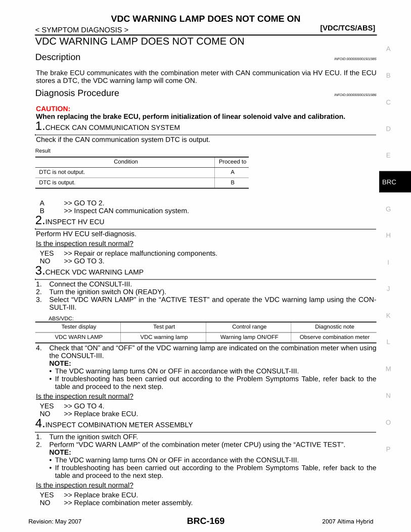
VDC WARNING LAMP DOES NOT COME ON[VDC/TCS/ABS]
C
D
E
G
H
I
J
K
L
M
A
B
RC
N
O
P
< SYMPTOM DIAGNOSIS >
B
VDC WARNING LAMP DOES NOT COME ON
Description INFOID:0000000001501985
The brake ECU communicates with the combination meter with CAN communication via HV ECU. If the ECUstores a DTC, the VDC warning lamp will come ON.
Diagnosis Procedure INFOID:0000000001501986
CAUTION:When replacing the brake ECU, perform initialization of linear solenoid valve and calibration.
1.CHECK CAN COMMUNICATION SYSTEM
Check if the CAN communication system DTC is output.
Result
A >> GO TO 2.B >> Inspect CAN communication system.
2.INSPECT HV ECU
Perform HV ECU self-diagnosis.Is the inspection result normal?YES >> Repair or replace malfunctioning components.NO >> GO TO 3.
3.CHECK VDC WARNING LAMP
1. Connect the CONSULT-III.2. Turn the ignition switch ON (READY).3. Select “VDC WARN LAMP” in the “ACTIVE TEST” and operate the VDC warning lamp using the CON-
SULT-III.
ABS/VDC:
4. Check that “ON” and “OFF” of the VDC warning lamp are indicated on the combination meter when usingthe CONSULT-III.NOTE:• The VDC warning lamp turns ON or OFF in accordance with the CONSULT-III.• If troubleshooting has been carried out according to the Problem Symptoms Table, refer back to the
table and proceed to the next step.Is the inspection result normal?YES >> GO TO 4.NO >> Replace brake ECU.
4.INSPECT COMBINATION METER ASSEMBLY
1. Turn the ignition switch OFF.2. Perform “VDC WARN LAMP” of the combination meter (meter CPU) using the “ACTIVE TEST”.
NOTE:• The VDC warning lamp turns ON or OFF in accordance with the CONSULT-III.• If troubleshooting has been carried out according to the Problem Symptoms Table, refer back to the
table and proceed to the next step.Is the inspection result normal?YES >> Replace brake ECU.NO >> Replace combination meter assembly.
Condition Proceed to
DTC is not output. A
DTC is output. B
Tester display Test part Control range Diagnostic note
VDC WARN LAMP VDC warning lamp Warning lamp ON/OFF Observe combination meter
BRC-169
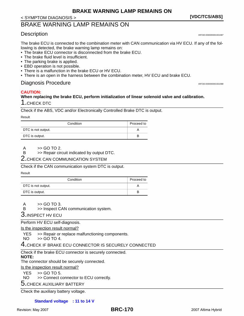
[VDC/TCS/ABS]BRAKE WARNING LAMP REMAINS ON
< SYMPTOM DIAGNOSIS >
BRAKE WARNING LAMP REMAINS ON
Description INFOID:0000000001501987
The brake ECU is connected to the combination meter with CAN communication via HV ECU. If any of the fol-lowing is detected, the brake warning lamp remains on:• The brake ECU connector is disconnected from the brake ECU.• The brake fluid level is insufficient.• The parking brake is applied.• EBD operation is not possible.• There is a malfunction in the brake ECU or HV ECU.• There is an open in the harness between the combination meter, HV ECU and brake ECU.
Diagnosis Procedure INFOID:0000000001501988
CAUTION:When replacing the brake ECU, perform initialization of linear solenoid valve and calibration.
1.CHECK DTC
Check if the ABS, VDC and/or Electronically Controlled Brake DTC is output.
Result
A >> GO TO 2.B >> Repair circuit indicated by output DTC.
2.CHECK CAN COMMUNICATION SYSTEM
Check if the CAN communication system DTC is output.
Result
A >> GO TO 3.B >> Inspect CAN communication system.
3.INSPECT HV ECU
Perform HV ECU self-diagnosis.Is the inspection result normal?YES >> Repair or replace malfunctioning components.NO >> GO TO 4.
4.CHECK IF BRAKE ECU CONNECTOR IS SECURELY CONNECTED
Check if the brake ECU connector is securely connected.NOTE:The connector should be securely connected.Is the inspection result normal?YES >> GO TO 5.NO >> Connect connector to ECU correctly.
5.CHECK AUXILIARY BATTERY
Check the auxiliary battery voltage.
Condition Proceed to
DTC is not output. A
DTC is output. B
Condition Proceed to
DTC is not output. A
DTC is output. B
Standard voltage : 11 to 14 V
BRC-170
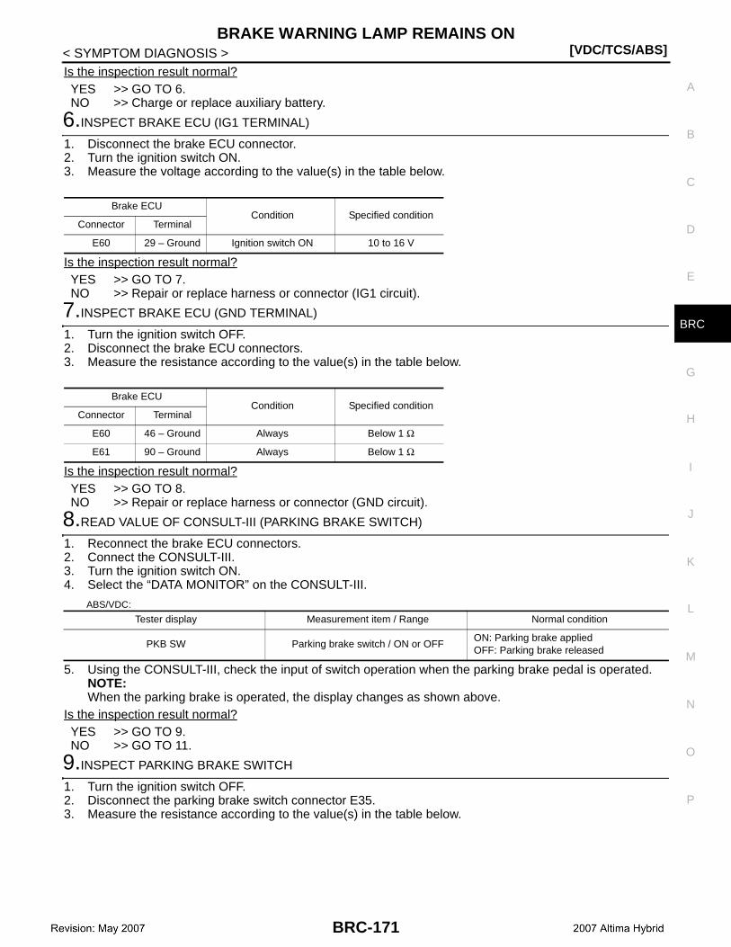
BRAKE WARNING LAMP REMAINS ON[VDC/TCS/ABS]
C
D
E
G
H
I
J
K
L
M
A
B
RC
N
O
P
< SYMPTOM DIAGNOSIS >
B
Is the inspection result normal?YES >> GO TO 6.NO >> Charge or replace auxiliary battery.
6.INSPECT BRAKE ECU (IG1 TERMINAL)
1. Disconnect the brake ECU connector.2. Turn the ignition switch ON.3. Measure the voltage according to the value(s) in the table below.
Is the inspection result normal?YES >> GO TO 7.NO >> Repair or replace harness or connector (IG1 circuit).
7.INSPECT BRAKE ECU (GND TERMINAL)
1. Turn the ignition switch OFF.2. Disconnect the brake ECU connectors.3. Measure the resistance according to the value(s) in the table below.
Is the inspection result normal?YES >> GO TO 8.NO >> Repair or replace harness or connector (GND circuit).
8.READ VALUE OF CONSULT-III (PARKING BRAKE SWITCH)
1. Reconnect the brake ECU connectors.2. Connect the CONSULT-III.3. Turn the ignition switch ON.4. Select the “DATA MONITOR” on the CONSULT-III.
ABS/VDC:
5. Using the CONSULT-III, check the input of switch operation when the parking brake pedal is operated.NOTE:When the parking brake is operated, the display changes as shown above.
Is the inspection result normal?YES >> GO TO 9.NO >> GO TO 11.
9.INSPECT PARKING BRAKE SWITCH
1. Turn the ignition switch OFF.2. Disconnect the parking brake switch connector E35.3. Measure the resistance according to the value(s) in the table below.
Brake ECUCondition Specified condition
Connector Terminal
E60 29 – Ground Ignition switch ON 10 to 16 V
Brake ECUCondition Specified condition
Connector Terminal
E60 46 – Ground Always Below 1 Ω
E61 90 – Ground Always Below 1 Ω
Tester display Measurement item / Range Normal condition
PKB SW Parking brake switch / ON or OFFON: Parking brake appliedOFF: Parking brake released
BRC-171
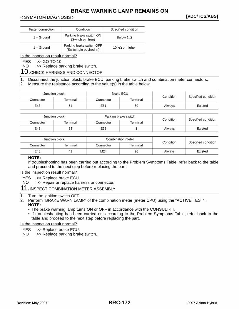
[VDC/TCS/ABS]BRAKE WARNING LAMP REMAINS ON
< SYMPTOM DIAGNOSIS >
Is the inspection result normal?YES >> GO TO 10.NO >> Replace parking brake switch.
10.CHECK HARNESS AND CONNECTOR
1. Disconnect the junction block, brake ECU, parking brake switch and combination meter connectors.2. Measure the resistance according to the value(s) in the table below.
NOTE:If troubleshooting has been carried out according to the Problem Symptoms Table, refer back to the tableand proceed to the next step before replacing the part.
Is the inspection result normal?YES >> Replace brake ECU.NO >> Repair or replace harness or connector.
11.INSPECT COMBINATION METER ASSEMBLY
1. Turn the ignition switch OFF.2. Perform “BRAKE WARN LAMP” of the combination meter (meter CPU) using the “ACTIVE TEST”.
NOTE:• The brake warning lamp turns ON or OFF in accordance with the CONSULT-III.• If troubleshooting has been carried out according to the Problem Symptoms Table, refer back to the
table and proceed to the next step before replacing the part.Is the inspection result normal?YES >> Replace brake ECU.NO >> Replace parking brake switch.
Tester connection Condition Specified condition
1 – GroundParking brake switch ON
(Switch pin free)Below 1 Ω
1 – GroundParking brake switch OFF
(Switch pin pushed in)10 kΩ or higher
Junction block Brake ECUCondition Specified condition
Connector Terminal Connector Terminal
E48 54 E61 69 Always Existed
Junction block Parking brake switchCondition Specified condition
Connector Terminal Connector Terminal
E48 53 E35 1 Always Existed
Junction block Combination meterCondition Specified condition
Connector Terminal Connector Terminal
E48 41 M24 26 Always Existed
BRC-172
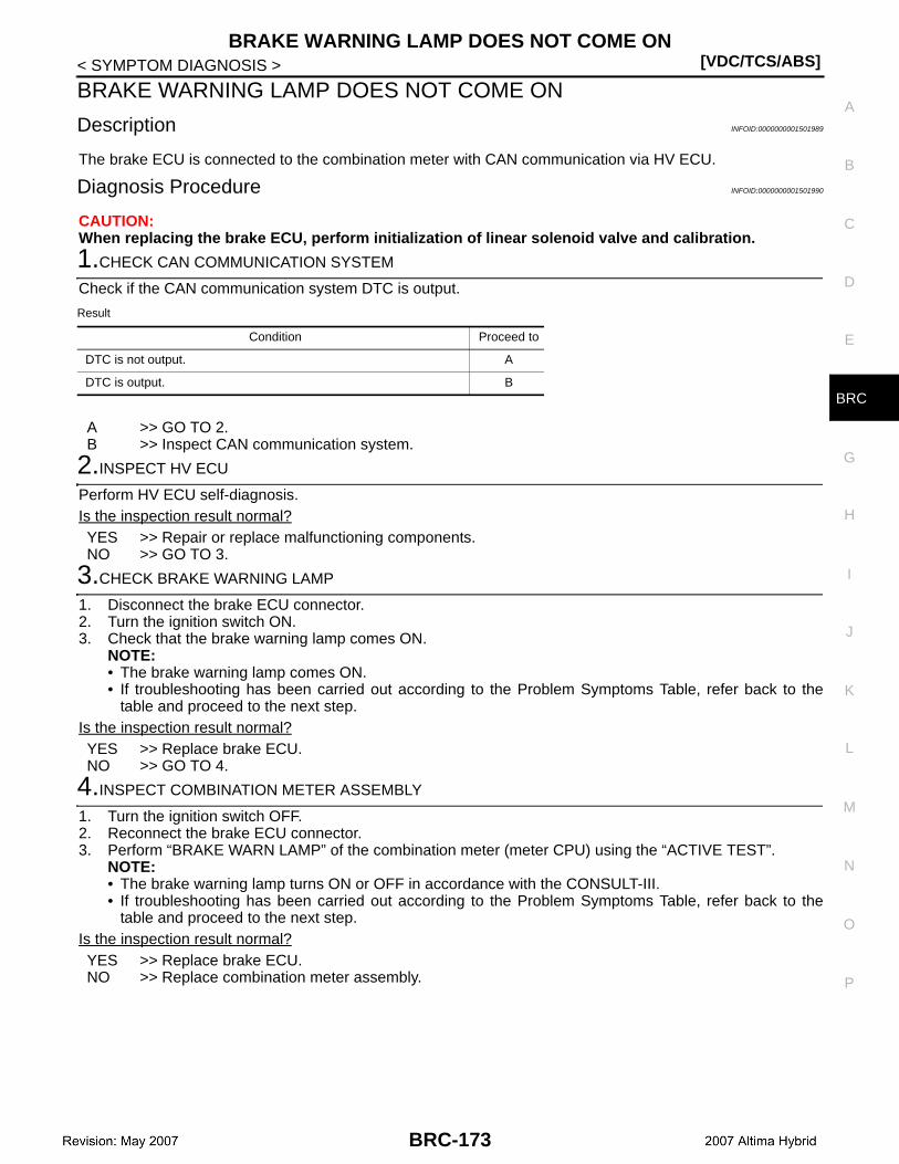
BRAKE WARNING LAMP DOES NOT COME ON[VDC/TCS/ABS]
C
D
E
G
H
I
J
K
L
M
A
B
RC
N
O
P
< SYMPTOM DIAGNOSIS >
B
BRAKE WARNING LAMP DOES NOT COME ON
Description INFOID:0000000001501989
The brake ECU is connected to the combination meter with CAN communication via HV ECU.
Diagnosis Procedure INFOID:0000000001501990
CAUTION:When replacing the brake ECU, perform initialization of linear solenoid valve and calibration.
1.CHECK CAN COMMUNICATION SYSTEM
Check if the CAN communication system DTC is output.
Result
A >> GO TO 2.B >> Inspect CAN communication system.
2.INSPECT HV ECU
Perform HV ECU self-diagnosis.Is the inspection result normal?YES >> Repair or replace malfunctioning components.NO >> GO TO 3.
3.CHECK BRAKE WARNING LAMP
1. Disconnect the brake ECU connector.2. Turn the ignition switch ON.3. Check that the brake warning lamp comes ON.
NOTE:• The brake warning lamp comes ON.• If troubleshooting has been carried out according to the Problem Symptoms Table, refer back to the
table and proceed to the next step.Is the inspection result normal?YES >> Replace brake ECU.NO >> GO TO 4.
4.INSPECT COMBINATION METER ASSEMBLY
1. Turn the ignition switch OFF.2. Reconnect the brake ECU connector.3. Perform “BRAKE WARN LAMP” of the combination meter (meter CPU) using the “ACTIVE TEST”.
NOTE:• The brake warning lamp turns ON or OFF in accordance with the CONSULT-III.• If troubleshooting has been carried out according to the Problem Symptoms Table, refer back to the
table and proceed to the next step.Is the inspection result normal?YES >> Replace brake ECU.NO >> Replace combination meter assembly.
Condition Proceed to
DTC is not output. A
DTC is output. B
BRC-173
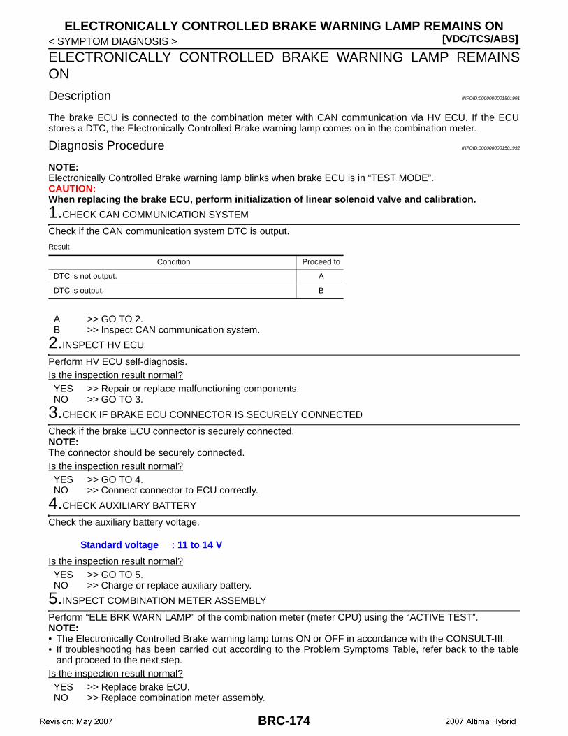
[VDC/TCS/ABS]ELECTRONICALLY CONTROLLED BRAKE WARNING LAMP REMAINS ON
< SYMPTOM DIAGNOSIS >
ELECTRONICALLY CONTROLLED BRAKE WARNING LAMP REMAINSON
Description INFOID:0000000001501991
The brake ECU is connected to the combination meter with CAN communication via HV ECU. If the ECUstores a DTC, the Electronically Controlled Brake warning lamp comes on in the combination meter.
Diagnosis Procedure INFOID:0000000001501992
NOTE:Electronically Controlled Brake warning lamp blinks when brake ECU is in “TEST MODE”.CAUTION:When replacing the brake ECU, perform initialization of linear solenoid valve and calibration.
1.CHECK CAN COMMUNICATION SYSTEM
Check if the CAN communication system DTC is output.
Result
A >> GO TO 2.B >> Inspect CAN communication system.
2.INSPECT HV ECU
Perform HV ECU self-diagnosis.Is the inspection result normal?YES >> Repair or replace malfunctioning components.NO >> GO TO 3.
3.CHECK IF BRAKE ECU CONNECTOR IS SECURELY CONNECTED
Check if the brake ECU connector is securely connected.NOTE:The connector should be securely connected.Is the inspection result normal?YES >> GO TO 4.NO >> Connect connector to ECU correctly.
4.CHECK AUXILIARY BATTERY
Check the auxiliary battery voltage.
Is the inspection result normal?YES >> GO TO 5.NO >> Charge or replace auxiliary battery.
5.INSPECT COMBINATION METER ASSEMBLY
Perform “ELE BRK WARN LAMP” of the combination meter (meter CPU) using the “ACTIVE TEST”.NOTE:• The Electronically Controlled Brake warning lamp turns ON or OFF in accordance with the CONSULT-III.• If troubleshooting has been carried out according to the Problem Symptoms Table, refer back to the table
and proceed to the next step.Is the inspection result normal?YES >> Replace brake ECU.NO >> Replace combination meter assembly.
Condition Proceed to
DTC is not output. A
DTC is output. B
Standard voltage : 11 to 14 V
BRC-174
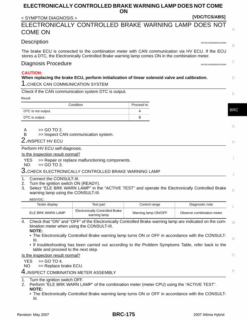
ELECTRONICALLY CONTROLLED BRAKE WARNING LAMP DOES NOT COME ON
[VDC/TCS/ABS]
C
D
E
G
H
I
J
K
L
M
A
B
RC
N
O
P
< SYMPTOM DIAGNOSIS >
B
ELECTRONICALLY CONTROLLED BRAKE WARNING LAMP DOES NOTCOME ON
Description INFOID:0000000001501993
The brake ECU is connected to the combination meter with CAN communication via HV ECU. If the ECUstores a DTC, the Electronically Controlled Brake warning lamp comes ON in the combination meter.
Diagnosis Procedure INFOID:0000000001501994
CAUTION:When replacing the brake ECU, perform initialization of linear solenoid valve and calibration.
1.CHECK CAN COMMUNICATION SYSTEM
Check if the CAN communication system DTC is output.
Result
A >> GO TO 2.B >> Inspect CAN communication system.
2.INSPECT HV ECU
Perform HV ECU self-diagnosis.Is the inspection result normal?YES >> Repair or replace malfunctioning components.NO >> GO TO 3.
3.CHECK ELECTRONICALLY CONTROLLED BRAKE WARNING LAMP
1. Connect the CONSULT-III.2. Turn the ignition switch ON (READY).3. Select “ELE BRK WARN LAMP” in the “ACTIVE TEST” and operate the Electronically Controlled Brake
warning lamp using the CONSULT-III.
ABS/VDC:
4. Check that “ON” and “OFF” of the Electronically Controlled Brake warning lamp are indicated on the com-bination meter when using the CONSULT-III.NOTE:• The Electronically Controlled Brake warning lamp turns ON or OFF in accordance with the CONSULT-
III.• If troubleshooting has been carried out according to the Problem Symptoms Table, refer back to the
table and proceed to the next step.Is the inspection result normal?YES >> GO TO 4.NO >> Replace brake ECU.
4.INSPECT COMBINATION METER ASSEMBLY
1. Turn the ignition switch OFF.2. Perform “ELE BRK WARN LAMP” of the combination meter (meter CPU) using the “ACTIVE TEST”.
NOTE:• The Electronically Controlled Brake warning lamp turns ON or OFF in accordance with the CONSULT-
III.
Condition Proceed to
DTC is not output. A
DTC is output. B
Tester display Test part Control range Diagnostic note
ELE BRK WARN LAMPElectronically Controlled Brake
warning lamp Warning lamp ON/OFF Observe combination meter
BRC-175
[VDC/TCS/ABS]
ELECTRONICALLY CONTROLLED BRAKE WARNING LAMP DOES NOT COME ON
< SYMPTOM DIAGNOSIS >• If troubleshooting has been carried out according to the Problem Symptoms Table, refer back to the
table and proceed to the next step.Is the inspection result normal?YES >> Replace brake ECU.NO >> Replace combination meter assembly.
BRC-176
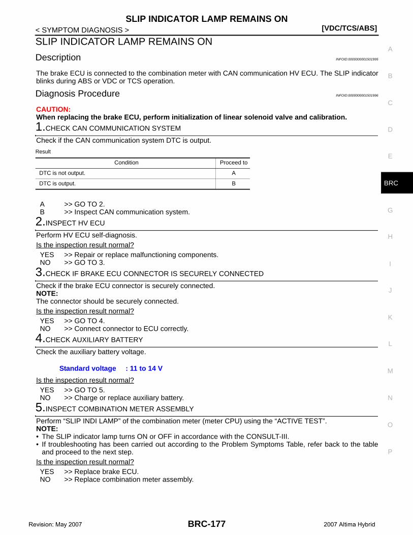
SLIP INDICATOR LAMP REMAINS ON[VDC/TCS/ABS]
C
D
E
G
H
I
J
K
L
M
A
B
RC
N
O
P
< SYMPTOM DIAGNOSIS >
B
SLIP INDICATOR LAMP REMAINS ON
Description INFOID:0000000001501995
The brake ECU is connected to the combination meter with CAN communication HV ECU. The SLIP indicatorblinks during ABS or VDC or TCS operation.
Diagnosis Procedure INFOID:0000000001501996
CAUTION:When replacing the brake ECU, perform initialization of linear solenoid valve and calibration.
1.CHECK CAN COMMUNICATION SYSTEM
Check if the CAN communication system DTC is output.
Result
A >> GO TO 2.B >> Inspect CAN communication system.
2.INSPECT HV ECU
Perform HV ECU self-diagnosis.Is the inspection result normal?YES >> Repair or replace malfunctioning components.NO >> GO TO 3.
3.CHECK IF BRAKE ECU CONNECTOR IS SECURELY CONNECTED
Check if the brake ECU connector is securely connected.NOTE:The connector should be securely connected.Is the inspection result normal?YES >> GO TO 4.NO >> Connect connector to ECU correctly.
4.CHECK AUXILIARY BATTERY
Check the auxiliary battery voltage.
Is the inspection result normal?YES >> GO TO 5.NO >> Charge or replace auxiliary battery.
5.INSPECT COMBINATION METER ASSEMBLY
Perform “SLIP INDI LAMP” of the combination meter (meter CPU) using the “ACTIVE TEST”.NOTE:• The SLIP indicator lamp turns ON or OFF in accordance with the CONSULT-III.• If troubleshooting has been carried out according to the Problem Symptoms Table, refer back to the table
and proceed to the next step.Is the inspection result normal?YES >> Replace brake ECU.NO >> Replace combination meter assembly.
Condition Proceed to
DTC is not output. A
DTC is output. B
Standard voltage : 11 to 14 V
BRC-177
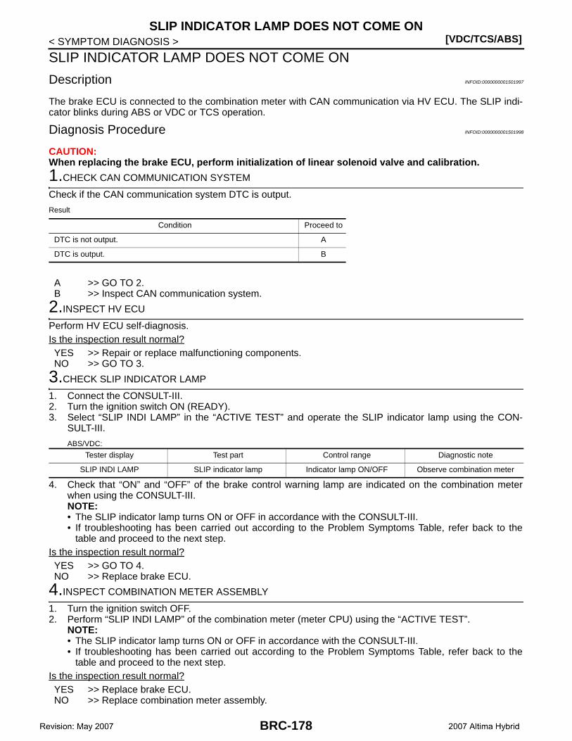
[VDC/TCS/ABS]SLIP INDICATOR LAMP DOES NOT COME ON
< SYMPTOM DIAGNOSIS >
SLIP INDICATOR LAMP DOES NOT COME ON
Description INFOID:0000000001501997
The brake ECU is connected to the combination meter with CAN communication via HV ECU. The SLIP indi-cator blinks during ABS or VDC or TCS operation.
Diagnosis Procedure INFOID:0000000001501998
CAUTION:When replacing the brake ECU, perform initialization of linear solenoid valve and calibration.
1.CHECK CAN COMMUNICATION SYSTEM
Check if the CAN communication system DTC is output.
Result
A >> GO TO 2.B >> Inspect CAN communication system.
2.INSPECT HV ECU
Perform HV ECU self-diagnosis.Is the inspection result normal?YES >> Repair or replace malfunctioning components.NO >> GO TO 3.
3.CHECK SLIP INDICATOR LAMP
1. Connect the CONSULT-III.2. Turn the ignition switch ON (READY).3. Select “SLIP INDI LAMP” in the “ACTIVE TEST” and operate the SLIP indicator lamp using the CON-
SULT-III.
ABS/VDC:
4. Check that “ON” and “OFF” of the brake control warning lamp are indicated on the combination meterwhen using the CONSULT-III.NOTE:• The SLIP indicator lamp turns ON or OFF in accordance with the CONSULT-III.• If troubleshooting has been carried out according to the Problem Symptoms Table, refer back to the
table and proceed to the next step.Is the inspection result normal?YES >> GO TO 4.NO >> Replace brake ECU.
4.INSPECT COMBINATION METER ASSEMBLY
1. Turn the ignition switch OFF.2. Perform “SLIP INDI LAMP” of the combination meter (meter CPU) using the “ACTIVE TEST”.
NOTE:• The SLIP indicator lamp turns ON or OFF in accordance with the CONSULT-III.• If troubleshooting has been carried out according to the Problem Symptoms Table, refer back to the
table and proceed to the next step.Is the inspection result normal?YES >> Replace brake ECU.NO >> Replace combination meter assembly.
Condition Proceed to
DTC is not output. A
DTC is output. B
Tester display Test part Control range Diagnostic note
SLIP INDI LAMP SLIP indicator lamp Indicator lamp ON/OFF Observe combination meter
BRC-178
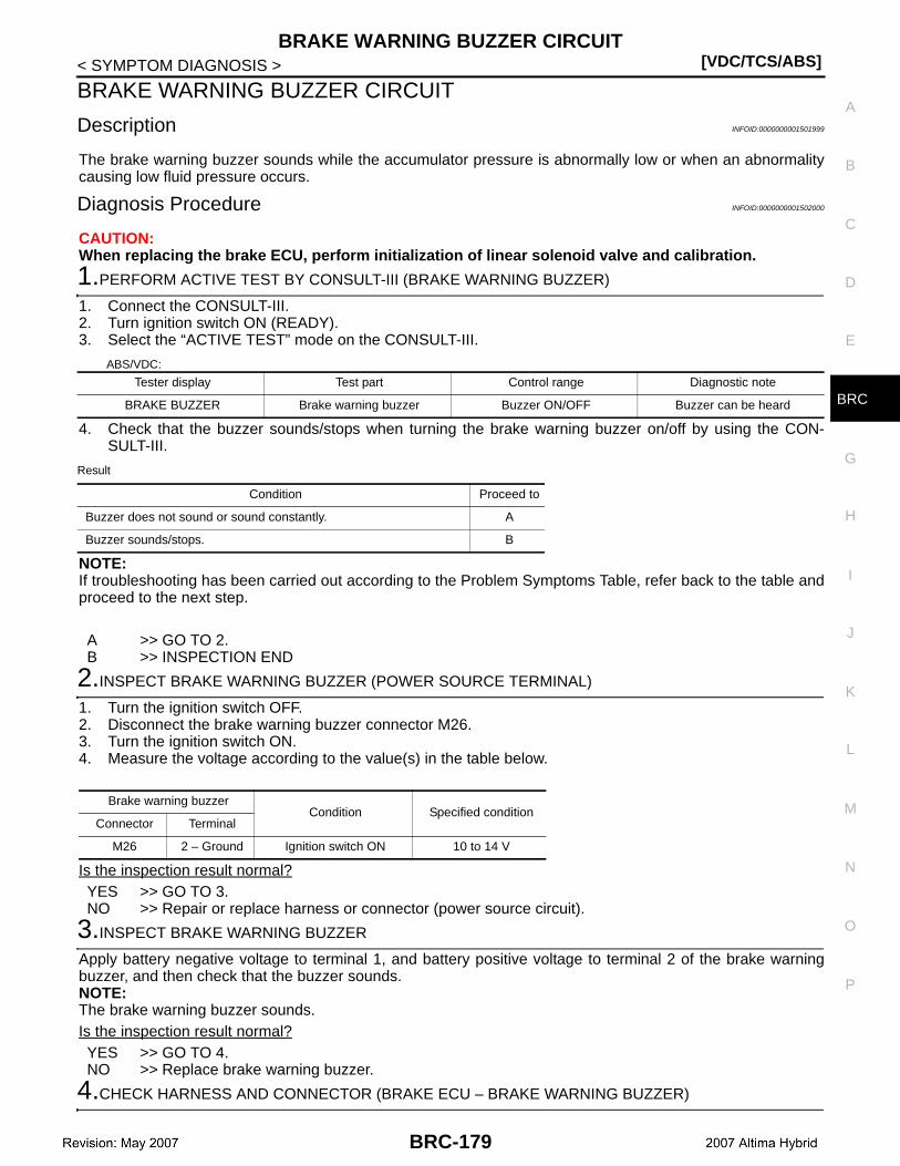
BRAKE WARNING BUZZER CIRCUIT[VDC/TCS/ABS]
C
D
E
G
H
I
J
K
L
M
A
B
RC
N
O
P
< SYMPTOM DIAGNOSIS >
B
BRAKE WARNING BUZZER CIRCUIT
Description INFOID:0000000001501999
The brake warning buzzer sounds while the accumulator pressure is abnormally low or when an abnormalitycausing low fluid pressure occurs.
Diagnosis Procedure INFOID:0000000001502000
CAUTION:When replacing the brake ECU, perform initialization of linear solenoid valve and calibration.
1.PERFORM ACTIVE TEST BY CONSULT-III (BRAKE WARNING BUZZER)
1. Connect the CONSULT-III.2. Turn ignition switch ON (READY).3. Select the “ACTIVE TEST” mode on the CONSULT-III.
ABS/VDC:
4. Check that the buzzer sounds/stops when turning the brake warning buzzer on/off by using the CON-SULT-III.
Result
NOTE:If troubleshooting has been carried out according to the Problem Symptoms Table, refer back to the table andproceed to the next step.
A >> GO TO 2.B >> INSPECTION END
2.INSPECT BRAKE WARNING BUZZER (POWER SOURCE TERMINAL)
1. Turn the ignition switch OFF.2. Disconnect the brake warning buzzer connector M26.3. Turn the ignition switch ON.4. Measure the voltage according to the value(s) in the table below.
Is the inspection result normal?YES >> GO TO 3.NO >> Repair or replace harness or connector (power source circuit).
3.INSPECT BRAKE WARNING BUZZER
Apply battery negative voltage to terminal 1, and battery positive voltage to terminal 2 of the brake warningbuzzer, and then check that the buzzer sounds.NOTE:The brake warning buzzer sounds.Is the inspection result normal?YES >> GO TO 4.NO >> Replace brake warning buzzer.
4.CHECK HARNESS AND CONNECTOR (BRAKE ECU – BRAKE WARNING BUZZER)
Tester display Test part Control range Diagnostic note
BRAKE BUZZER Brake warning buzzer Buzzer ON/OFF Buzzer can be heard
Condition Proceed to
Buzzer does not sound or sound constantly. A
Buzzer sounds/stops. B
Brake warning buzzerCondition Specified condition
Connector Terminal
M26 2 – Ground Ignition switch ON 10 to 14 V
BRC-179

[VDC/TCS/ABS]BRAKE WARNING BUZZER CIRCUIT
< SYMPTOM DIAGNOSIS >1. Turn the ignition switch OFF.2. Disconnect the brake ECU connector.3. Measure the resistance according to the value(s) in the table below.
Is the inspection result normal?YES >> GO TO 5.NO >> Repair or replace harness or connector.
5.INSPECT BRAKE ECU (GND TERMINAL)
1. Disconnect the brake ECU connectors.2. Measure the resistance according to the value(s) in the table below.
NOTE:If troubleshooting has been carried out according to the Problem Symptoms Table, refer back to the tableand proceed to the next step.
Is the inspection result normal?YES >> Replace brake ECU.NO >> Repair or replace harness or connector (GND circuit).
Brake ECU Brake warning buzzer— Condition Specified condition
Connector Terminal Connector Terminal
E60 39 M26 1 — Always Below 1 Ω
E60 39 — — Ground Always 10 kΩ or higher
E60 23 M26 2 — Always Below 1 Ω
E60 23 — — Ground Always 10 kΩ or higher
Brake ECUCondition Specified condition
Connector Terminal
E60 46 – Ground Always Below 1 Ω
E61 90 – Ground Always Below 1 Ω
BRC-180
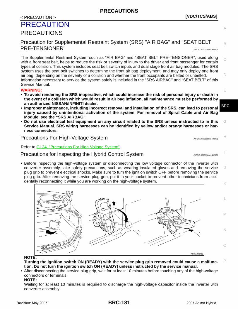
PRECAUTIONS[VDC/TCS/ABS]
C
D
E
G
H
I
J
K
L
M
A
B
RC
N
O
P
< PRECAUTION >
B
PRECAUTIONPRECAUTIONS
Precaution for Supplemental Restraint System (SRS) "AIR BAG" and "SEAT BELT PRE-TENSIONER" INFOID:0000000001502001
The Supplemental Restraint System such as “AIR BAG” and “SEAT BELT PRE-TENSIONER”, used alongwith a front seat belt, helps to reduce the risk or severity of injury to the driver and front passenger for certaintypes of collision. This system includes seat belt switch inputs and dual stage front air bag modules. The SRSsystem uses the seat belt switches to determine the front air bag deployment, and may only deploy one frontair bag, depending on the severity of a collision and whether the front occupants are belted or unbelted.Information necessary to service the system safely is included in the “SRS AIRBAG” and “SEAT BELT” of thisService Manual.WARNING:• To avoid rendering the SRS inoperative, which could increase the risk of personal injury or death in
the event of a collision which would result in air bag inflation, all maintenance must be performed byan authorized NISSAN/INFINITI dealer.
• Improper maintenance, including incorrect removal and installation of the SRS, can lead to personalinjury caused by unintentional activation of the system. For removal of Spiral Cable and Air BagModule, see the “SRS AIRBAG”.
• Do not use electrical test equipment on any circuit related to the SRS unless instructed to in thisService Manual. SRS wiring harnesses can be identified by yellow and/or orange harnesses or har-ness connectors.
Precautions For High-Voltage System INFOID:0000000001502002
Refer to GI-24, "Precautions For High-Voltage System".
Precautions for Inspecting the Hybrid Control System INFOID:0000000001502003
• Before inspecting the high-voltage system or disconnecting the low voltage connector of the inverter withconverter assembly, take safety precautions, such as wearing insulated gloves and removing the serviceplug grip to prevent electrical shocks. Make sure to turn the ignition switch OFF before removing the serviceplug grip. After removing the service plug grip, put it in your pocket to prevent other technicians from acci-dentally reconnecting it while you are working on the high-voltage system.
NOTE:Turning the ignition switch ON (READY) with the service plug grip removed could cause a malfunc-tion. Do not turn the ignition switch ON (READY) unless instructed by the service manual.
• After disconnecting the service plug grip, wait for at least 10 minutes before touching any of the high-voltageconnectors or terminals.NOTE:Waiting for at least 10 minutes is required to discharge the high-voltage capacitor inside the inverter withconverter assembly.
ALCIA0007ZZ
BRC-181
[VDC/TCS/ABS]PRECAUTIONS
< PRECAUTION >• Turn the ignition switch OFF, wear insulated gloves, and disconnect the negative terminal of the auxiliary
battery before touching any of the orange-colored wires of the high-voltage system.• Turn the ignition switch OFF before performing any resistance checks.• Turn the ignition switch OFF before disconnecting or reconnecting any connectors.
Electronically Controlled Brake System INFOID:0000000001502004
CAUTION:When disconnecting the negative battery terminal, initialize the following system after the terminal isreconnected:
TROUBLESHOOTING PRECAUTIONS1. When there is a malfunction with terminal contact points or part installation problems, removal and instal-
lation of the suspected problem parts may return the system to the normal condition either completely ortemporarily.
2. In order to determine the malfunctioning area, be sure to check the conditions at the time the malfunctionoccurred, such as DTC output and the Freeze Frame Data, and record it before disconnecting each con-nector or removing and installing parts.
3. Since the system may be influenced by malfunctions in systems other than the brake control system, besure to check for DTCs in order systems.
HANDLING PRECAUTIONS1. Do not remove or install Electronically Controlled Brake parts such as the steering angle sensor, yaw rate/
side/decel G sensor or brake stroke sensor except when required, as they cannot be adjusted correctlyafter removal or installation.
2. Be sure to perform preparation before work and confirmation after work is completed by following thedirection in the repair manual when working on the Electronically Controlled Brake system.
3. Be sure to remove and install the ECU, actuator, each sensor, etc. with the ignition switch OFF unless it isnot specified in the inspection procedure.
4. Be sure to remove the 2 main relays before removal and installation, or replacement of the ElectronicallyControlled Brake parts.
5. The removal or installation of the actuator, master cylinder or stroke simulator as well as some other pro-cedures can cause the fluid level to drop below the fluid reservoir port. If this happens when performingsuch work, be sure to remove the 2 motor relays until the bleeding of the air in the pipeline is completed.NOTE:• When the pump motor is operated with the air in the brake actuator hose, bleeding the air becomes dif-
ficult due to air in the actuator.• The brake ECU may operate the stroke simulator and drive the pump motor even when the ignition
switch OFF.• With the ignition switch OFF, the brake ECU can be operated for 2 minutes after the brake operation is
finished.6. Removal of the main relay and motor relay.a. Wait for 2 minutes after turning the ignition switch OFF, stopping the brake pedal operation and closing the
driver door before removing the 2 relays.NOTE:The above situation occurs when the pump motor operates to prepare for the next operation just beforethe brake control system turns OFF.
7. If the ECU, brake actuator, or a sensor has been removed and installed, it is necessary to check the sys-tem for problems after the parts have been reassembled. Check for DTCs using the CONSULT-III, alsocheck that system functions and signals received by the ECU are normal using Test Mode.
DTC PRECAUTIONWarnings for some DTCs cannot be cleared only by repairing the malfunctioning parts. If the warning is dis-played after repair work, the DTC should be cleared after turning the ignition switch OFF.CAUTION:If a DTC for a malfunctioning part reappears after it was cleared, then it has been stored again.
System
SFI system
BRC-182
PRECAUTIONS[VDC/TCS/ABS]
C
D
E
G
H
I
J
K
L
M
A
B
RC
N
O
P
< PRECAUTION >
B
CHASSIS DYNAMOMETER PRECAUTIONWhen checking with chassis dynamometer, place CONSULT-III in “INSPECTION MODE” to deactivate VDCand TCS. Refer to HBC-103, "MODE 1 : Diagnosis Description" (MODE 1), HBC-104, "MODE 2 : DiagnosisDescription" (MODE 2).NOTE:The vehicle may move unexpectedly out of the dynamometer because of TCS and VDC operations.CAUTION:• Make sure that the brake control warning, master caution indicator lamps blink and “CHECK VDC
SYSTEM” is displayed on the multi information display (Test Mode is achieved).• Secure the vehicle with the lock chain for safety.
CAN COMMUNICATION SYSTEM PRECAUTIONS1. The CAN communication system is used for the data communication between the brake ECU, the steer-
ing angle sensor, the yaw rate/side/decel G sensor and other ECUs. If there is trouble in the CAN commu-nication line, corresponding DTCs in the communication line are output.
2. If the DTC in the CAN communication line is output, repair the malfunction in the communication line andtroubleshoot the Electronically Controlled Brake system while data communication is normal.
3. In order to enable CAN communication, a specific type of wiring is used for the CAN communication lines.The wiring is used for each communication line is a twisted pair of wires that have an equal length. Abypass wire should not be used, because the data being transmitted will be corrupted.
BRC-183
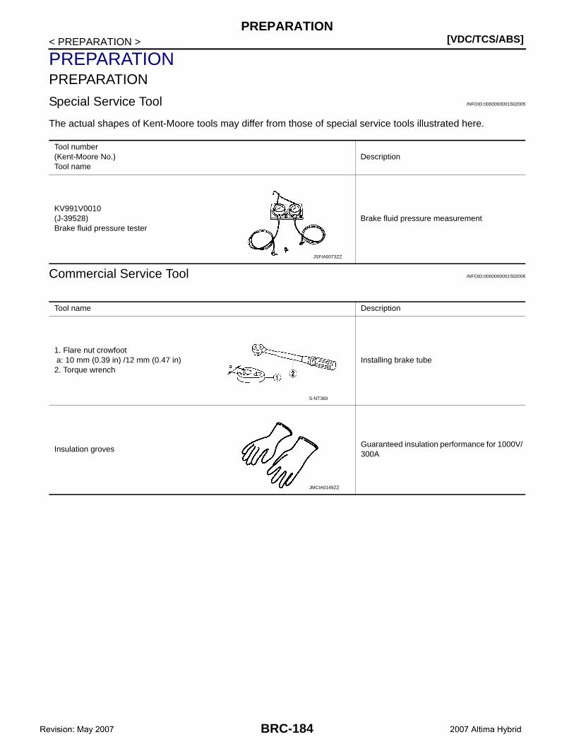
[VDC/TCS/ABS]PREPARATION
< PREPARATION >
PREPARATIONPREPARATION
Special Service Tool INFOID:0000000001502005
The actual shapes of Kent-Moore tools may differ from those of special service tools illustrated here.
Commercial Service Tool INFOID:0000000001502006
Tool number(Kent-Moore No.)Tool name
Description
KV991V0010(J-39528)Brake fluid pressure tester
Brake fluid pressure measurement
JSFIA0073ZZ
Tool name Description
1. Flare nut crowfoot a: 10 mm (0.39 in) /12 mm (0.47 in)2. Torque wrench
Installing brake tube
Insulation grovesGuaranteed insulation performance for 1000V/300A
S-NT360
JMCIA0149ZZ
BRC-184

BRAKE ECU[VDC/TCS/ABS]
C
D
E
G
H
I
J
K
L
M
A
B
RC
N
O
P
< ON-VEHICLE MAINTENANCE >
B
ON-VEHICLE MAINTENANCEBRAKE ECU
Inspection INFOID:0000000001502007
INSPECT BRAKE ECU1. Measure the voltage between each terminal or between each terminal and body ground.2. Connect the CONSULT-III, and check the communication condition with the brake ECU.CAUTION:• Inspection should be performed from the back of the connector with the connected to the brake
ECU.• The voltage between the terminals of the brake actuator assembly may become 0 V due to the fail
safe function when the brake warning lamp comes ON (malfunctioning).
BRC-185
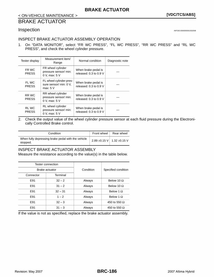
[VDC/TCS/ABS]BRAKE ACTUATOR
< ON-VEHICLE MAINTENANCE >
BRAKE ACTUATOR
Inspection INFOID:0000000001502008
INSPECT BRAKE ACTUATOR ASSEMBLY OPERATION1. On “DATA MONITOR”, select “FR WC PRESS”, “FL WC PRESS”, “RR WC PRESS” and “RL WC
PRESS”, and check the wheel cylinder pressure.
2. Check the output value of the wheel cylinder pressure sensor at each fluid pressure during the Electroni-cally Controlled Brake control.
INSPECT BRAKE ACTUATOR ASSEMBLYMeasure the resistance according to the value(s) in the table below.
If the value is not as specified, replace the brake actuator assembly.
Tester displayMeasurement item/
RangeNormal condition Diagnostic note
FR WC PRESS
FR wheel cylinder pressure sensor/ min: 0 V, max: 5 V
When brake pedal is released: 0.3 to 0.9 V
—
FL WC PRESS
FL wheel cylinder pres-sure sensor/ min: 0 V, max: 5 V
When brake pedal is released: 0.3 to 0.9 V
—
RR WC PRESS
RR wheel cylinder pressure sensor/ min: 0 V, max: 5 V
When brake pedal is released: 0.3 to 0.9 V
—
RL WC PRESS
RL wheel cylinder pressure sensor/ min: 0 V, max: 5 V
When brake pedal is released: 0.3 to 0.9 V
—
Condition Front wheel Rear wheel
When fully depressing brake pedal with the vehicle stopped.
2.89 ±0.15 V 1.32 ±0.15 V
Tester connection
Condition Specified conditionBrake actuator
Connector Terminal
E91 32 – 2 Always Below 10 Ω
E91 31 – 2 Always Below 10 Ω
E91 32 – 31 Always Below 1 Ω
E91 1 – 2 Always Below 1 Ω
E91 32 – 3 Always 450 to 550 Ω
E91 31 – 3 Always 450 to 550 Ω
BRC-186

WHEEL SENSOR[VDC/TCS/ABS]
C
D
E
G
H
I
J
K
L
M
A
B
RC
N
O
P
< ON-VEHICLE MAINTENANCE >
B
WHEEL SENSOR
Inspection INFOID:0000000001502009
INSPECT FRONT WHEEL SENSOR1. Inspect the front wheel sensor. If any of the following occurs, replace the front wheel sensor with a new
one:• The surface of the front wheel sensor is cracked, dented, or chipped off.• The connector or wire harness is scratched, cracked, or damaged.• The front wheel sensor has been dropped.
2. Measure the resistance according to the value(s) in the table below.
RH
LH
If the value is not as specified, replace the front wheel sensor.
INSPECT REAR WHEEL SENSOR1. Inspect the rear wheel sensor. If any of the following occurs, replace the rear wheel sensor with a new
one:• The surface of the rear wheel sensor is cracked, dented, or chipped off.• The connector is scratched, cracked, or damaged.• The skid control sensor has been dropped.
2. Measure the resistance to the value(s) in the table below.
RH
LH
If the value is not as specified, replace rear wheel sensor.
Tester connection
— Condition Specified conditionFront wheel sensor
Connector Terminal
E41 1 – 2 — Always Not existed
E41 1 Ground Always Existed
E41 2 Ground Always Existed
Tester connection
— Condition Specified conditionFront wheel sensor
Connector Terminal
E19 1 – 2 — Always Not existed
E19 1 Ground Always Existed
E19 2 Ground Always Existed
Tester connection
— Condition Specified conditionFront wheel sensor
Connector Terminal
B43 3 – 4 — Always Not existed
B43 3 Ground Always Existed
B43 4 Ground Always Existed
Tester connection
— Condition Specified conditionFront wheel sensor
Connector Terminal
B43 1 – 2 — Always Not existed
B43 1 Ground Always Existed
B43 2 Ground Always Existed
BRC-187
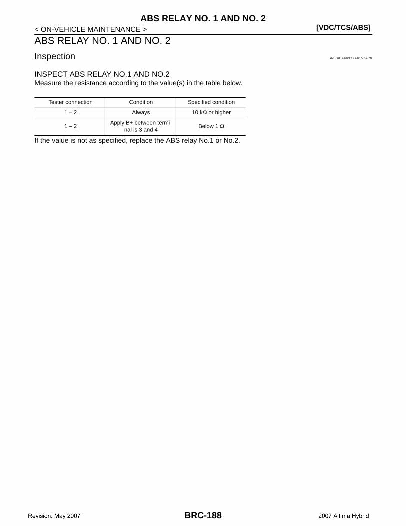
[VDC/TCS/ABS]ABS RELAY NO. 1 AND NO. 2
< ON-VEHICLE MAINTENANCE >
ABS RELAY NO. 1 AND NO. 2
Inspection INFOID:0000000001502010
INSPECT ABS RELAY NO.1 AND NO.2Measure the resistance according to the value(s) in the table below.
If the value is not as specified, replace the ABS relay No.1 or No.2.
Tester connection Condition Specified condition
1 – 2 Always 10 kΩ or higher
1 – 2Apply B+ between termi-
nal is 3 and 4Below 1 Ω
BRC-188
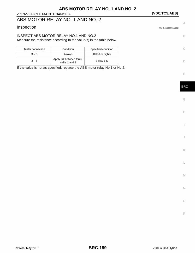
ABS MOTOR RELAY NO. 1 AND NO. 2[VDC/TCS/ABS]
C
D
E
G
H
I
J
K
L
M
A
B
RC
N
O
P
< ON-VEHICLE MAINTENANCE >
B
ABS MOTOR RELAY NO. 1 AND NO. 2
Inspection INFOID:0000000001502011
INSPECT ABS MOTOR RELAY NO.1 AND NO.2Measure the resistance according to the value(s) in the table below.
If the value is not as specified, replace the ABS motor relay No.1 or No.2.
Tester connection Condition Specified condition
3 – 5 Always 10 kΩ or higher
3 – 5Apply B+ between termi-
nal is 1 and 2Below 1 Ω
BRC-189
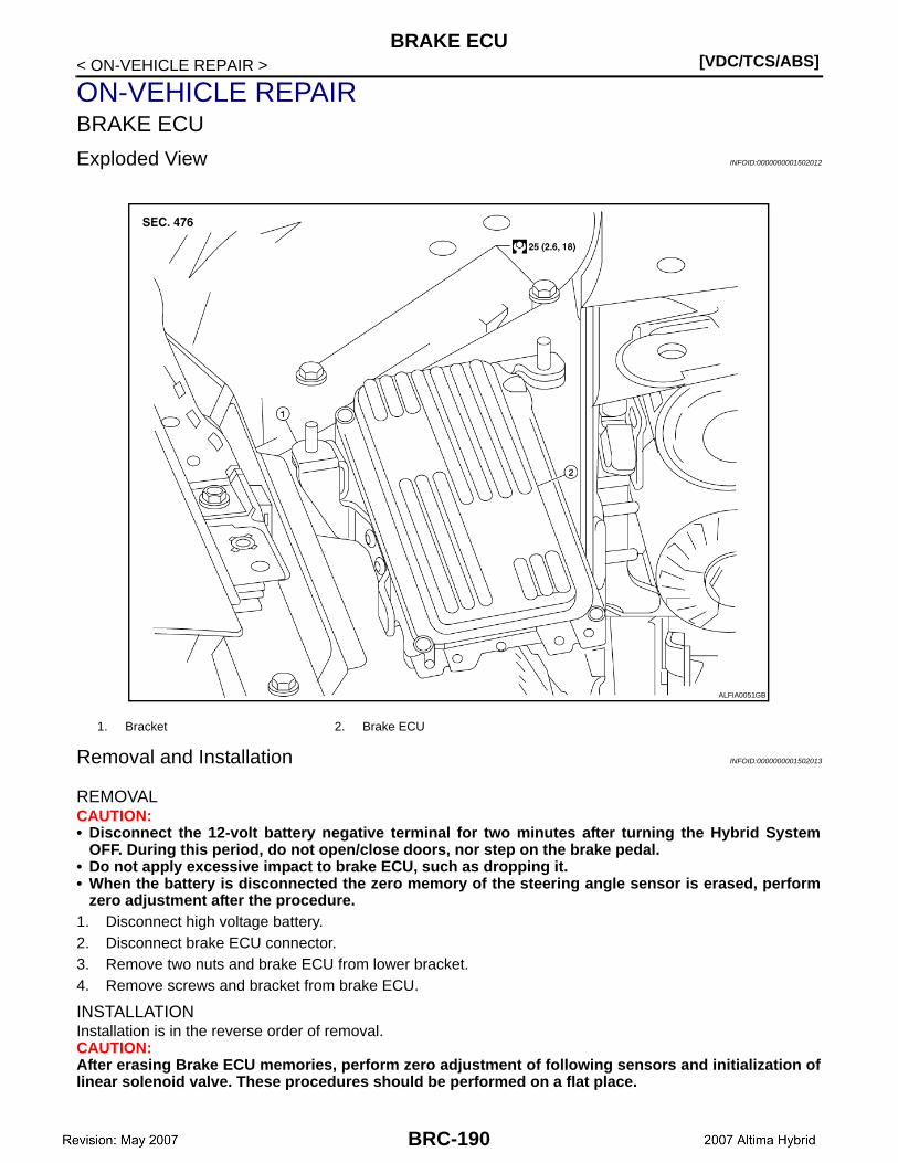
[VDC/TCS/ABS]BRAKE ECU
< ON-VEHICLE REPAIR >
ON-VEHICLE REPAIRBRAKE ECU
Exploded View INFOID:0000000001502012
Removal and Installation INFOID:0000000001502013
REMOVALCAUTION:• Disconnect the 12-volt battery negative terminal for two minutes after turning the Hybrid System
OFF. During this period, do not open/close doors, nor step on the brake pedal.• Do not apply excessive impact to brake ECU, such as dropping it.• When the battery is disconnected the zero memory of the steering angle sensor is erased, perform
zero adjustment after the procedure.1. Disconnect high voltage battery.2. Disconnect brake ECU connector.3. Remove two nuts and brake ECU from lower bracket.4. Remove screws and bracket from brake ECU.
INSTALLATIONInstallation is in the reverse order of removal.CAUTION:After erasing Brake ECU memories, perform zero adjustment of following sensors and initialization oflinear solenoid valve. These procedures should be performed on a flat place.
1. Bracket 2. Brake ECU
ALFIA0051GB
BRC-190
BRAKE ECU[VDC/TCS/ABS]
C
D
E
G
H
I
J
K
L
M
A
B
RC
N
O
P
< ON-VEHICLE REPAIR >
B
• Steering angle sensor. Refer to BRC-9, "PERFORM ZERO POINT OF STEERING ANGLE SENSOR :Description".
• Yaw rate/side. Refer to BRC-8, "PERFORM ZERO POINT OF YAW RATE/SIDE/DECEL G SENSOR :Description".
• Brake stroke sensor. Refer to BRC-9, "PERFORM ADJUSTMENT OF STROKE SENSOR : Descrip-tion".
• Linear solenoid valve. Refer to BRC-7, "PERFORM INITIALIZATION OF LINEAR SOLENOID VALVEAND CALIBRATION : Description".
BRC-191
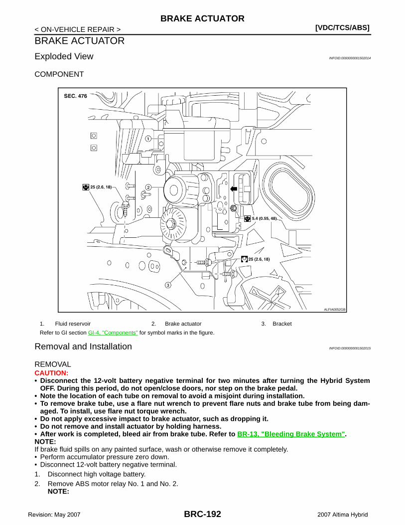
[VDC/TCS/ABS]BRAKE ACTUATOR
< ON-VEHICLE REPAIR >
BRAKE ACTUATOR
Exploded View INFOID:0000000001502014
COMPONENT
Removal and Installation INFOID:0000000001502015
REMOVALCAUTION:• Disconnect the 12-volt battery negative terminal for two minutes after turning the Hybrid System
OFF. During this period, do not open/close doors, nor step on the brake pedal.• Note the location of each tube on removal to avoid a misjoint during installation.• To remove brake tube, use a flare nut wrench to prevent flare nuts and brake tube from being dam-
aged. To install, use flare nut torque wrench.• Do not apply excessive impact to brake actuator, such as dropping it.• Do not remove and install actuator by holding harness.• After work is completed, bleed air from brake tube. Refer to BR-13, "Bleeding Brake System".NOTE:If brake fluid spills on any painted surface, wash or otherwise remove it completely.• Perform accumulator pressure zero down.• Disconnect 12-volt battery negative terminal.1. Disconnect high voltage battery.2. Remove ABS motor relay No. 1 and No. 2.
NOTE:
1. Fluid reservoir 2. Brake actuator 3. Bracket
Refer to GI section GI-4, "Components" for symbol marks in the figure.
ALFIA0052GB
BRC-192
BRAKE ACTUATOR[VDC/TCS/ABS]
C
D
E
G
H
I
J
K
L
M
A
B
RC
N
O
P
< ON-VEHICLE REPAIR >
B
If the pump motor operates while air remains inside the brake actuator hose, the air will enter the actuatorresulting in difficulty in bleeding the brakes.
3. Relieve fuel pressure. Refer to FL-4, "Quick Connector".4. Drain brake fluid. Refer to BR-13, "Bleeding Brake System".5. Remove front wiper arms. Refer to WW-35, "FRONT WIPER ARMS : Removal and Installation".6. Remove cowl top and cowl top extension. Refer to EXT-17, "Removal and Installation".7. Disconnect washer hose.8. Remove tower bar. Refer to FSU-13, "Exploded View".9. Remove air cleaner duct and air duct hose. Refer to EM-23, "Removal and Installation".10. Remove fuel tube. Refer to EM-34, "Removal and Installation".11. Remove intake manifold assembly and place throttle body assembly aside. Refer to EM-24, "Removal
and Installation".12. Remove brake reservoir.13. Release brake actuator connector lever, then disconnect brake actuator connector in the direction of
arrow as shown in BRC-192, "Exploded View".14. Loosen brake tube flare nuts, then remove brake tubes from brake actuator.
NOTE:Do not damage the brake lines.
15. Remove brake actuator nuts.16. Remove brake actuator from vehicle.17. Remove bracket as necessary.
INSTALLATIONNote the following, and install in the reverse order of removal.CAUTION:• Before servicing, disconnect the 12-volt battery negative terminal.• Do not remove the hole plug before connecting the brake line because a new brake actuator assem-
bly is filled with brake fluid.• Use a torque wrench with a fulcrum length of 250mm (9.84 in).• This torque value is effective when flare nut crowfoot is parallel to a torque wrench.• To remove brake tube, use a flare nut wrench to prevent flare nuts and brake tube from being dam-
aged. To install, use flare nut torque wrench.• Do not apply excessive impact to brake actuator, such as dropping it.• Do not remove and install brake actuator by holding harness.• After work is completed, bleed air from brake tube. Refer to BR-13, "Bleeding Brake System".• After installing connector in the brake actuator, make sure connector is securely locked. • After erasing Brake ECU memories, perform zero adjustment of following sensors and initialization
of linear solenoid valve. These prcedures should be performed on a flat place.- Steering angle sensor. Refer to BRC-9, "PERFORM ZERO POINT OF STEERING ANGLE SENSOR :
Description".- Yaw rate/side. Refer to BRC-8, "PERFORM ZERO POINT OF YAW RATE/SIDE/DECEL G SENSOR :
Description".- Brake stroke sensor. Refer to BRC-9, "PERFORM ADJUSTMENT OF STROKE SENSOR : Descrip-
tion".- Linear solenoid valve. Refer to BRC-7, "PERFORM INITIALIZATION OF LINEAR SOLENOID VALVE
AND CALIBRATION : Description".
Disposal INFOID:0000000001502016
DISPOSAL OF BRAKE ACTUATOR
BRC-193

[VDC/TCS/ABS]BRAKE ACTUATOR
< ON-VEHICLE REPAIR >Using a drill, slowly make a hole on the circumference made by thecenter points of A and discharge the gas.CAUTION:Be sure to wear protective glasses to protect the eyes fromfragments that may become airborne due to high pressure.NOTE:• The hole may be drilled up to approximately 5 to 10 mm (0.20 to
0.39 in) away from the circumference made by the center point ofA without problem.
• The gas is nitrogen, which is colorless, odorless and harmless.
JSFIA0080GB
BRC-194

WHEEL SENSOR[VDC/TCS/ABS]
C
D
E
G
H
I
J
K
L
M
A
B
RC
N
O
P
< ON-VEHICLE REPAIR >
B
WHEEL SENSOR
Exploded View INFOID:0000000001502017
Removal and Installation INFOID:0000000001502018
CAUTION:• Be careful not to damage wheel sensor edge and sensor rotor teeth.• When removing the front or rear wheel hub assembly, first remove the wheel sensor from the assem-
bly. Failure to do so may result in damage to the wheel sensor wires making the sensor inoperative.• Pull out the wheel sensor, being careful to turn it as little as possible. Do not pull on the wheel sen-
sor harness.• Installation should be performed while paying attention to the following, and then tighten mounting
bolts and nuts to the specified torque.- Check if foreign objects such as iron fragments are adhered to the pick-up part of the sensor or to
the inside of the hole for mounting the wheel sensor, or if a foreign object is caught on the mountingsurface of the rotor. If something wrong is found, fix it and then install the wheel sensor.
REMOVAL
Front
1. Remove wheel and tire using power tool.2. Partially remove front wheel fender protector. Refer to EXT-18, "Removal and Installation".3. Remove wheel sensor bolt and wheel sensor.4. Remove harness wire from mounts and disconnect wheel sensor harness connector.
RearNOTE:Both rear wheel sensors share one harness and must be replaced as an assembly.1. Remove wheel and tire using power tool.2. Remove wheel sensor bolts and wheel sensors from both rear wheels.3. Remove harness wire from mounts and harness wire clips from suspension member.
1. Front wheel sensor 2. Rear wheel sensor ⇐ Front
AWFIA0008GB
BRC-195
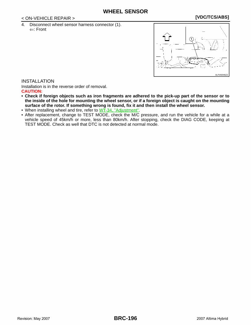
[VDC/TCS/ABS]WHEEL SENSOR
< ON-VEHICLE REPAIR >4. Disconnect wheel sensor harness connector (1).
⇐: Front
INSTALLATIONInstallation is in the reverse order of removal.CAUTION:• Check if foreign objects such as iron fragments are adhered to the pick-up part of the sensor or to
the inside of the hole for mounting the wheel sensor, or if a foreign object is caught on the mountingsurface of the rotor. If something wrong is found, fix it and then install the wheel sensor.
• When installing wheel and tire, refer to WT-34, "Adjustment".• After replacement, change to TEST MODE, check the M/C pressure, and run the vehicle for a while at a
vehicle speed of 45km/h or more, less than 80km/h. After stopping, check the DIAG CODE, keeping atTEST MODE. Check as well that DTC is not detected at normal mode.
ALFIA0046ZZ
BRC-196
SENSOR ROTOR[VDC/TCS/ABS]
C
D
E
G
H
I
J
K
L
M
A
B
RC
N
O
P
< ON-VEHICLE REPAIR >
B
SENSOR ROTOR
Removal and Installation INFOID:0000000001502019
The front and rear wheel sensor rotors are an integral part of the wheel hub assemblies and can not be disas-sembled. When replacing the sensor rotor, replace the wheel hub assembly. Refer to FAX-7, "Removal andInstallation" (Front), RAX-6, "Removal and Installation" (Rear).• When installing wheel and tire, refer to WT-34, "Adjustment".• After replacement, change to TEST MODE, check the M/C pressure, and run the vehicle for a while at a
vehicle speed of 45km/h or more, less than 80km/h. After stopping, check the DIAG CODE, keeping atTEST MODE. Check as well that DTC is not detected at normal mode.
BRC-197
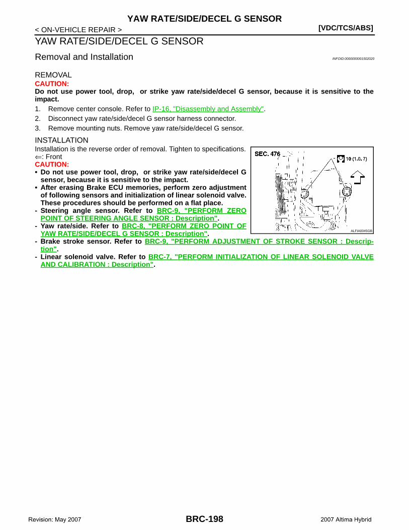
[VDC/TCS/ABS]YAW RATE/SIDE/DECEL G SENSOR
< ON-VEHICLE REPAIR >
YAW RATE/SIDE/DECEL G SENSOR
Removal and Installation INFOID:0000000001502020
REMOVALCAUTION:Do not use power tool, drop, or strike yaw rate/side/decel G sensor, because it is sensitive to theimpact.1. Remove center console. Refer to IP-16, "Disassembly and Assembly".2. Disconnect yaw rate/side/decel G sensor harness connector.3. Remove mounting nuts. Remove yaw rate/side/decel G sensor.
INSTALLATIONInstallation is the reverse order of removal. Tighten to specifications.⇐: FrontCAUTION:• Do not use power tool, drop, or strike yaw rate/side/decel G
sensor, because it is sensitive to the impact.• After erasing Brake ECU memories, perform zero adjustment
of following sensors and initialization of linear solenoid valve.These procedures should be performed on a flat place.
- Steering angle sensor. Refer to BRC-9, "PERFORM ZEROPOINT OF STEERING ANGLE SENSOR : Description".
- Yaw rate/side. Refer to BRC-8, "PERFORM ZERO POINT OFYAW RATE/SIDE/DECEL G SENSOR : Description".
- Brake stroke sensor. Refer to BRC-9, "PERFORM ADJUSTMENT OF STROKE SENSOR : Descrip-tion".
- Linear solenoid valve. Refer to BRC-7, "PERFORM INITIALIZATION OF LINEAR SOLENOID VALVEAND CALIBRATION : Description".
ALFIA0045GB
BRC-198

STEERING ANGLE SENSOR[VDC/TCS/ABS]
C
D
E
G
H
I
J
K
L
M
A
B
RC
N
O
P
< ON-VEHICLE REPAIR >
B
STEERING ANGLE SENSOR
Removal and Installation INFOID:0000000001502021
CAUTION:• Disconnect the 12-volt battery negative terminal two minutes after turning Hybrid System OFF. Dur-
ing this period, do not open/close doors, nor step on the brake pedal.
The steering angle sensor is part of the spiral cable assembly and should not be disassembled. When replac-ing steering angle sensor, replace the spiral cable assembly and steering angle sensor as a unit. Refer toSRS-6, "Removal and Installation".
CAUTION:After erasing Brake ECU memories, perform zero adjustment of following sensors and initialization oflinear solenoid valve. These procedures should be performed on a flat place.• Steering angle sensor. Refer to BRC-9, "PERFORM ZERO POINT OF STEERING ANGLE SENSOR :
Description".• Yaw rate/side. Refer to BRC-8, "PERFORM ZERO POINT OF YAW RATE/SIDE/DECEL G SENSOR :
Description".• Brake stroke sensor. Refer to BRC-9, "PERFORM ADJUSTMENT OF STROKE SENSOR : Descrip-
tion".• Linear solenoid valve. Refer to BRC-7, "PERFORM INITIALIZATION OF LINEAR SOLENOID VALVE
AND CALIBRATION : Description".
BRC-199

[VDC/TCS/ABS]BRAKE WARNING BUZZER
< ON-VEHICLE REPAIR >
BRAKE WARNING BUZZER
Removal and Installation INFOID:0000000001502022
Refer to BRC-15, "Component Parts Location" for brake warning buzzer location.1. Remove audio unit. Refer to AV-45, "Removal and Installation".2. Disconnect connector and remove brake warning buzzer.3. Installation is in the reverse order of removal.CAUTION:After the replacement, change the status of CONSULT-III to “ACTIVE TEST” and confirm the functionof the brake warning buzzer.
BRC-200
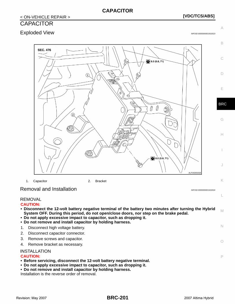
CAPACITOR[VDC/TCS/ABS]
C
D
E
G
H
I
J
K
L
M
A
B
RC
N
O
P
< ON-VEHICLE REPAIR >
B
CAPACITOR
Exploded View INFOID:0000000001502023
Removal and Installation INFOID:0000000001502024
REMOVALCAUTION:• Disconnect the 12-volt battery negative terminal of the battery two minutes after turning the Hybrid
System OFF. During this period, do not open/close doors, nor step on the brake pedal.• Do not apply excessive impact to capacitor, such as dropping it.• Do not remove and install capacitor by holding harness.1. Disconnect high voltage battery.2. Disconnect capacitor connector.3. Remove screws and capacitor.4. Remove bracket as necessary.
INSTALLATIONCAUTION:• Before servicing, disconnect the 12-volt battery negative terminal.• Do not apply excessive impact to capacitor, such as dropping it.• Do not remove and install capacitor by holding harness.Installation is the reverse order of removal.
1. Capacitor 2. Bracket
ALFIA0053GB
BRC-201
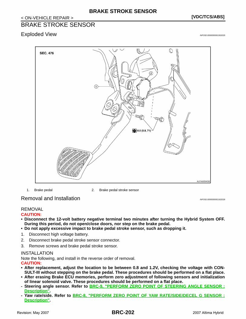
[VDC/TCS/ABS]BRAKE STROKE SENSOR
< ON-VEHICLE REPAIR >
BRAKE STROKE SENSOR
Exploded View INFOID:0000000001502025
Removal and Installation INFOID:0000000001502026
REMOVALCAUTION:• Disconnect the 12-volt battery negative terminal two minutes after turning the Hybrid System OFF.
During this period, do not open/close doors, nor step on the brake pedal.• Do not apply excessive impact to brake pedal stroke sensor, such as dropping it.1. Disconnect high voltage battery.2. Disconnect brake pedal stroke sensor connector.3. Remove screws and brake pedal stroke sensor.
INSTALLATIONNote the following, and install in the reverse order of removal.CAUTION:• After replacement, adjust the location to be between 0.8 and 1.2V, checking the voltage with CON-
SULT-III without stepping on the brake pedal. These procedures should be performed on a flat place.• After erasing Brake ECU memories, perform zero adjustment of following sensors and initialization
of linear solenoid valve. These procedures should be performed on a flat place.- Steering angle sensor. Refer to BRC-9, "PERFORM ZERO POINT OF STEERING ANGLE SENSOR :
Description".- Yaw rate/side. Refer to BRC-8, "PERFORM ZERO POINT OF YAW RATE/SIDE/DECEL G SENSOR :
Description".
1. Brake pedal 2. Brake pedal stroke sensor
ALFIA0054GB
BRC-202

BRAKE STROKE SENSOR[VDC/TCS/ABS]
C
D
E
G
H
I
J
K
L
M
A
B
RC
N
O
P
< ON-VEHICLE REPAIR >
B
- Brake stroke sensor. Refer to BRC-9, "PERFORM ADJUSTMENT OF STROKE SENSOR : Descrip-tion".
- Linear solenoid valve. Refer to BRC-7, "PERFORM INITIALIZATION OF LINEAR SOLENOID VALVEAND CALIBRATION : Description".
BRC-203
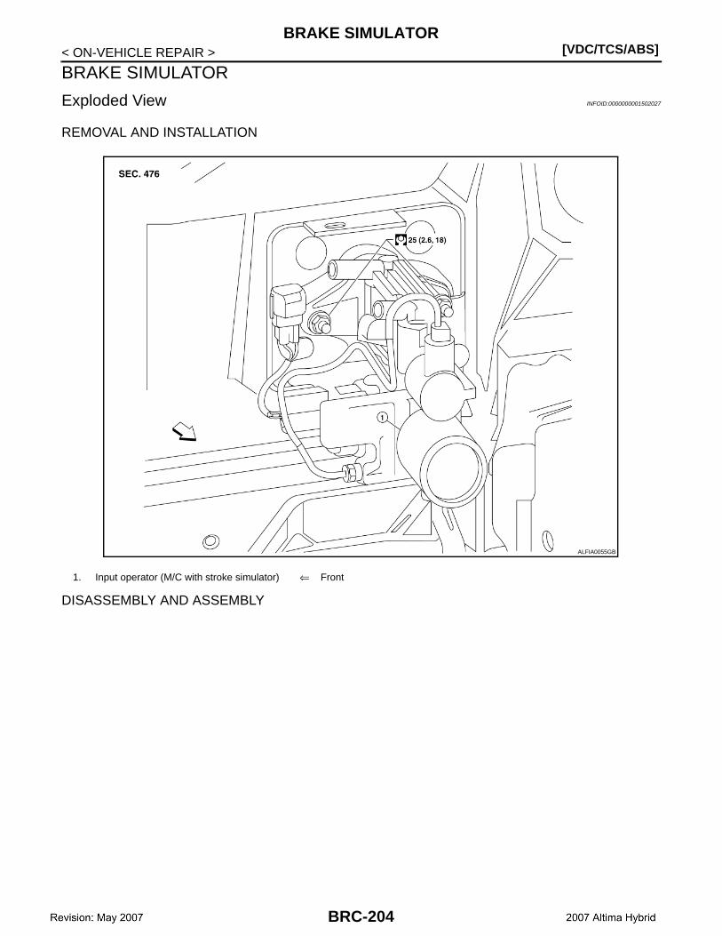
[VDC/TCS/ABS]BRAKE SIMULATOR
< ON-VEHICLE REPAIR >
BRAKE SIMULATOR
Exploded View INFOID:0000000001502027
REMOVAL AND INSTALLATION
DISASSEMBLY AND ASSEMBLY
1. Input operator (M/C with stroke simulator) ⇐ Front
ALFIA0055GB
BRC-204

BRAKE SIMULATOR[VDC/TCS/ABS]
C
D
E
G
H
I
J
K
L
M
A
B
RC
N
O
P
< ON-VEHICLE REPAIR >
B
Removal and Installation INFOID:0000000001502028
REMOVALCAUTION:• Disconnect the 12-volt battery negative terminal two minutes after turning the Hybrid System OFF.
During this period, do not open/close doors, nor step on the brake pedal.1. Disconnect high voltage battery.2. Disconnect input operator (M/C with stroke simulator) connector.3. Disconnect hoses from Input operator (M/C with stroke simulator).4. Remove brake pedal clevis pin. Refer to BR-18, "Exploded View".5. Remove nuts and input operator (M/C with stroke simulator).
1. Brake fluid reservior 2. Grommet 3. Master cylinder sub-assembly
4. Reservoir hose No.1 5. Reservoir hose No.2 6. Clamp
7. Master cylinder sub-assembly 8. Gasket 9. Brake simulator
10. Bracket 11. Gasket 12. Clevis
JSFIA0078GB
BRC-205
[VDC/TCS/ABS]BRAKE SIMULATOR
< ON-VEHICLE REPAIR >
INSTALLATIONNote the following, and install in the reverse order of removal.CAUTION:• Before servicing, disconnect the 12-volt battery negative terminal.• After the work is completed, bleed air from brake simulator and brake tube.• Do not bend or damage the brake line.• Do not allow any foreign material such as dirt and dust from entering the brake line from the con-
necting points.• Use a torque wrench with a fulcrum length of 250mm (9.84 in).• This torque value is effective when flare nut crowfoot is parallel to a torque wrench.• Don not reuse gasket.• After erasing Brake ECU memories, perform zero adjustment of following sensors and initialization
of linear solenoid valve. These procedures should be performed on a flat place.- Steering angle sensor. Refer to BRC-9, "PERFORM ZERO POINT OF STEERING ANGLE SENSOR :
Description".- Yaw rate/side. Refer to BRC-8, "PERFORM ZERO POINT OF YAW RATE/SIDE/DECEL G SENSOR :
Description".- Brake stroke sensor. Refer to BRC-9, "PERFORM ADJUSTMENT OF STROKE SENSOR : Descrip-
tion".- Linear solenoid valve. Refer to BRC-7, "PERFORM INITIALIZATION OF LINEAR SOLENOID VALVE
AND CALIBRATION : Description".
Disassembly and Assembly INFOID:0000000001502029
DISASSEMBLY1. Remove master cylinder sub-assembly mounting nuts.2. Loosen brake tube flare nuts, then remove brake tube from master cylinder sub-assembly and brake sim-
ulator.3. Remove master cylinder sub-assembly from bracket.4. Remove screw, brake fluid reservoir and grommets from master cylinder sub-assembly.5. Remove brake simulator mounting bolts.6. Remove brake simulator from bracket.
ASSEMBLYNote the following, and install in the reverse order of disassembly.CAUTION:• Do not reuse grommet and gasket.• Do not bend or damage the brake tube.• Do not allow any foreign matter such as dirt and dust to enter the brake line from the connecting
points.• Use a torque wrench with a fulcrum length of 250 mm (9.84 in).• This torque value is effective when flare nut crowfoot is parallel to a torque wrench.
BRC-206