bradley university department of electrical and computer engineering sr. capstone project advisor:...
Post on 22-Dec-2015
218 views
TRANSCRIPT
BRADLEY UNIVERSITY
Department of Electrical and Computer Engineering
Sr. Capstone Project
Advisor:
Dr. Anakwa
Student:
Paul Friend
Overview:
•Background Information
•Halbach Array
•Inductrack
•Sensors
•Propulsion Methods
•Controls
•Physical Design
•Theories
•Parts and Equipment
•Schedule
•Resources

Background InformationInductrack:
•Created by Richard F. Post in the late 1990’s at Lawrence Livermore National Laboratory
•20 meter test track
•Burst Propulsion

Background InformationInductrack:
•Contracted by NASA for Satellite Launcher
•Low-Speed Urban Maglev Program

Halbach Array•Created by Klaus Halbach
•Creates a strong, nearly one-sided magnet with a sinusoidal field by directing the magnetic fields.

Halbach Array•Standard Formation
•Expanded Wavlength
•Doubled Method
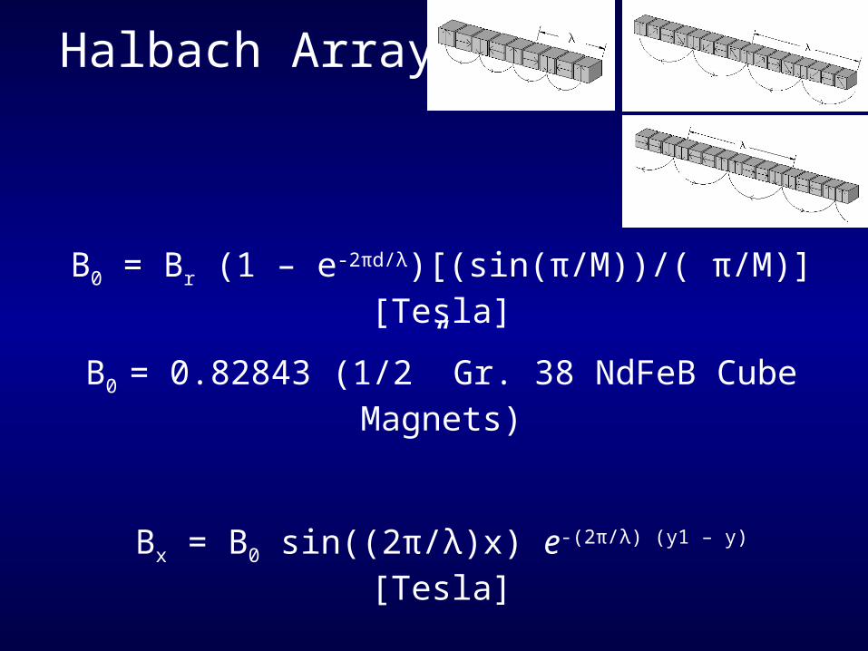
Halbach Array
B0 = Br (1 – e-2πd/λ)[(sin(π/M))/( π/M)] [Tesla]
B0 = 0.82843 (1/2” Gr. 38 NdFeB Cube Magnets)
Bx = B0 sin((2π/λ)x) e-(2π/λ) (y1 – y) [Tesla]
By = B0 cos((2π/λ)x) e-(2π/λ) (y1 – y) [Tesla]

Inductrack
Basic Methods:
•Array of Inductors
•Laminated Copper
•Laminated Aluminum

Inductrack
Array of Inductors
•Used in 1st Inductrack
•Insulated Litz-wire
•Ferrite Loading

Inductrack
Laminated Copper
•Square Litz-wire bulks
•Used for Low-Speed Urban Maglev Program

Inductrack
Laminated Copper & Aluminum
•Thin Sheets
•Slots cut to guide eddy currents
•Slots terminated at ends for “shorts”

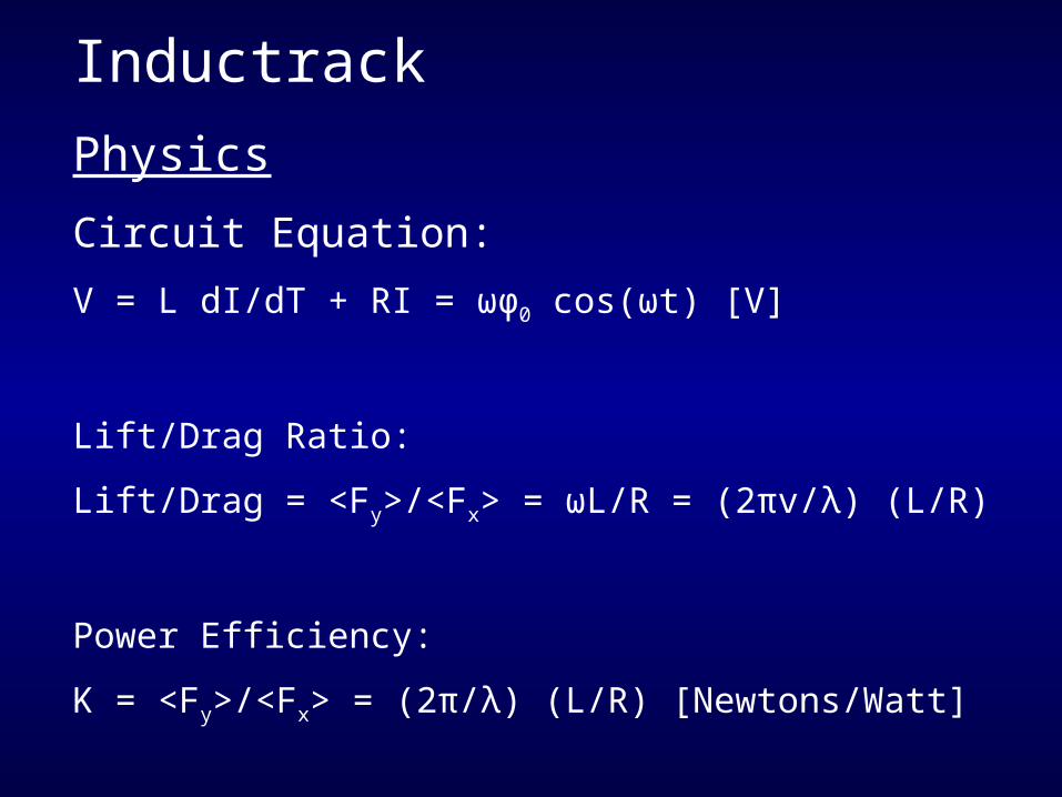
Inductrack
Physics
•Lenz’s Law
•Discovered in 1834
•Eddy currents created due to moving magnetic field
•(Not guided)
Inductrack
Physics
Circuit Equation:
V = L dI/dT + RI = ωφ0 cos(ωt) [V]
Lift/Drag Ratio:
Lift/Drag = <Fy>/<Fx> = ωL/R = (2πv/λ) (L/R)
Power Efficiency:
K = <Fy>/<Fx> = (2π/λ) (L/R) [Newtons/Watt]
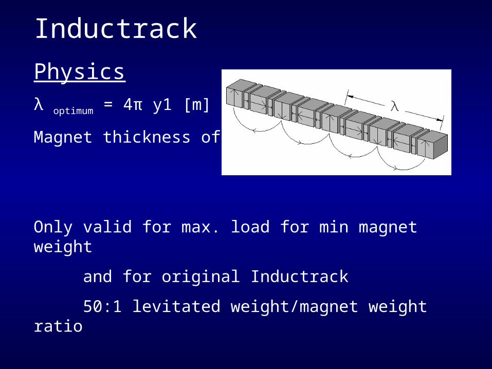
Inductrack
Physics
λ optimum = 4π y1 [m]
Magnet thickness of λ/5
Only valid for max. load for min magnet weight
and for original Inductrack
50:1 levitated weight/magnet weight ratio

Inductrack
Inductrack II
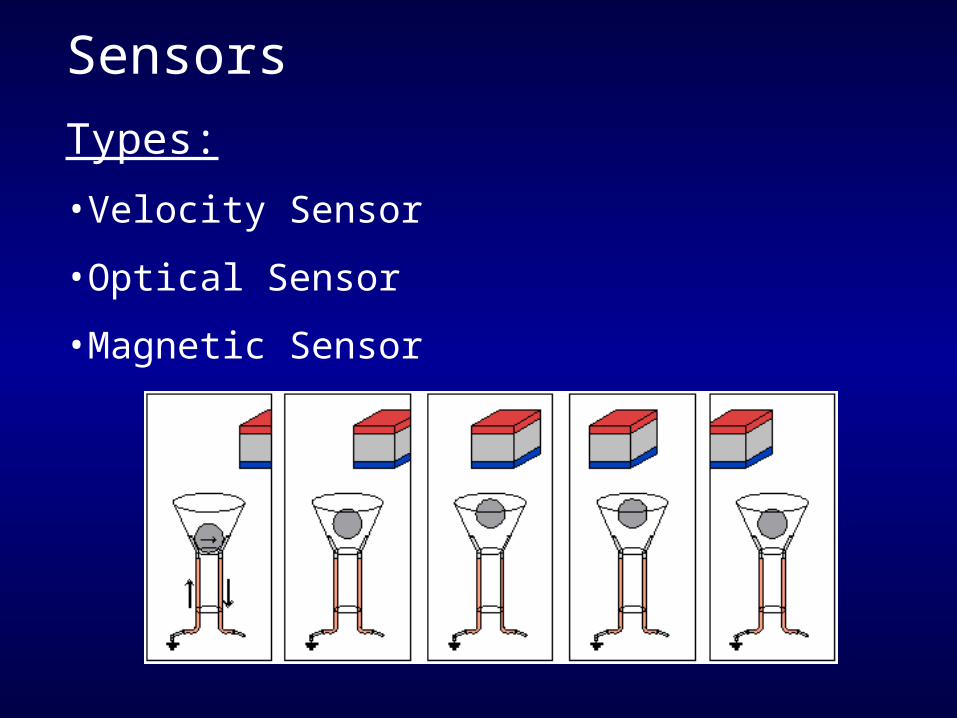
Sensors
Types:
•Velocity Sensor
•Optical Sensor
•Magnetic Sensor
PropulsionTypes:
•Linear Synchronous Motor (LSM)
•Linear Induction Motor (LIM)

PropulsionLinear Synchronous Motor (LSM)
•Used for Low-Speed Urban Maglev Program
•Allows for large air gap ~ 25 mm
•Varied 3-phase frequency and current for contols
•Solid copper cables and laminated iron rails
•Works with Halbach array
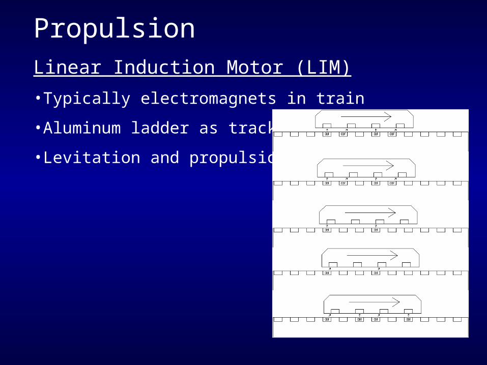
PropulsionLinear Induction Motor (LIM)
•Typically electromagnets in train
•Aluminum ladder as track
•Levitation and propulsion aquired

PropulsionModified Linear Induction Motor (LIM)
•Synchronized electromagnets
•Precision sensing required
•Controled via the current
PWM
Current Level

ControlsProperties to Control
(80515 Microcontroller Based)
•Levitation Hieght
•Direction
•Velocity

ControlsLevitation Height Control
•Theory of current Low-Speed Urban Maglev Program
•Height by causing a phase shift
•Compromises the structure
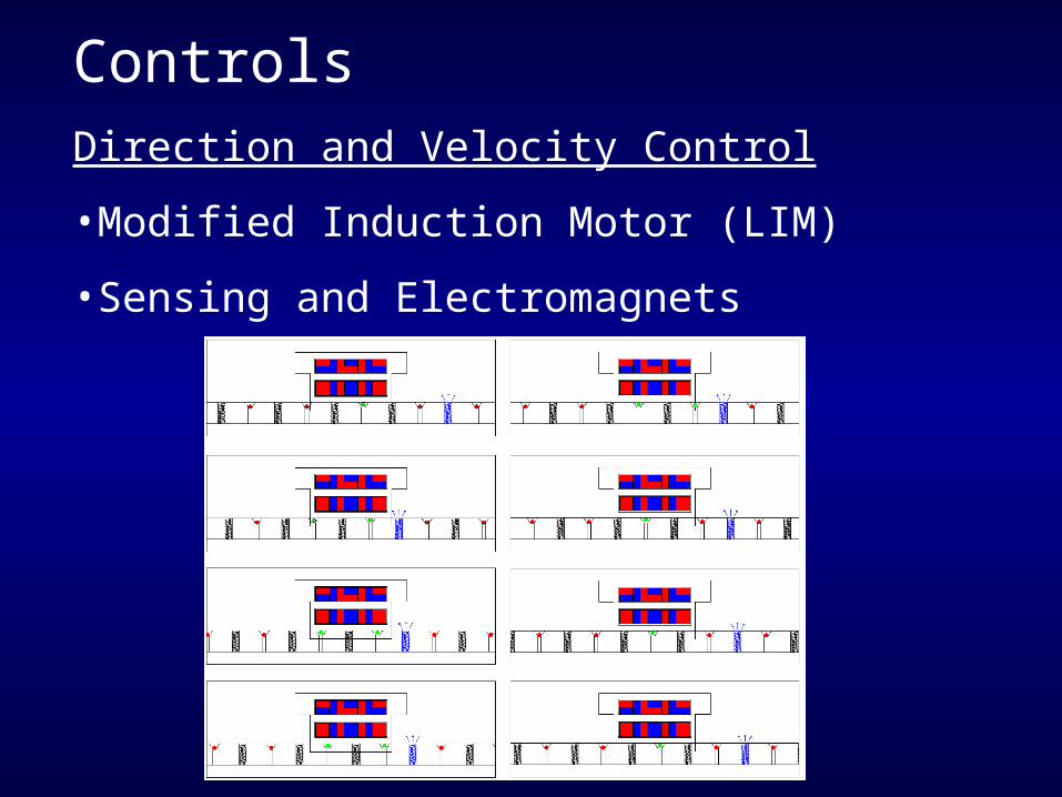
ControlsDirection and Velocity Control
•Modified Induction Motor (LIM)
•Sensing and Electromagnets

ControlsDirection and Velocity Control
•Inputs:
Mode of Operation
Velocity or Current
•Outputs:
Train Levitation
Train Propulsion
LCD Display
Train ControlSystem
Train:LevitationGuidancePropulsion
Mode of Operation
Velocity or Current
LCD

ControlsDirection and Velocity Control
Modes of Operation:0.) Open Loop Backwards Current Input1.) Closed Loop Backwards Velocity Input with Control2.) Backwards Coast with No Propulsion3.) Stop4.) Forwards Coast with No Propulsion5.) Closed Loop Forwards Velocity Input with Control6.) Open Loop Forwards Current Input
Train ControlSystem
Train:LevitationGuidancePropulsion
Mode of Operation
Velocity or Current
LCD
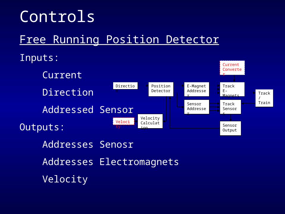
ControlsFree Running Position Detector
Inputs:
Current
Direction
Addressed Sensor
Outputs:
Addresses Senosr
Addresses Electromagnets
Velocity
Direction PositionDetector
E-MagnetAddresser
TrackE-Magnets
Track/Train
TrackSensors
SensorAddresser
SensorOutput
VelocityCalculation
CurrentConverter
Velocity
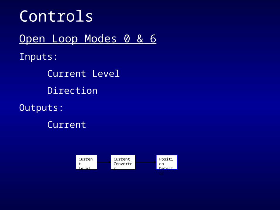
ControlsOpen Loop Modes 0 & 6
Inputs:
Current Level
Direction
Outputs:
Current
CurrentLevel
CurrentConverter
PositionDetector

ControlsClosed Loop Modes 1 & 5
Inputs:
Velocity
Direction
DesiredVelocity
CurrentAdjuster
CurrentConverter
PositionDetector
Velocity

ControlsCoast Modes 2 & 4
•Direction is indicated for sensor prediction
•Utilizes free running position detector with no current
•Velocity still displayed
Stop Mode 3
•Pulse electromagnets in front of train
•Position detector can not be used
•Details have not been worked out
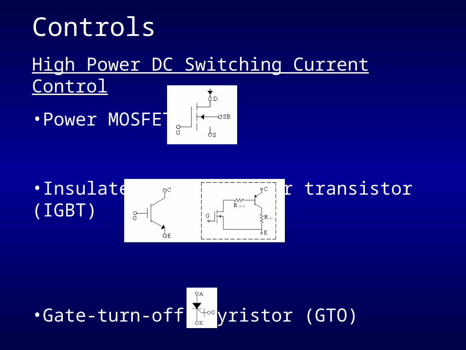
ControlsHigh Power DC Switching Current Control
•Power MOSFET
•Insulated -gate bipolar transistor (IGBT)
•Gate-turn-off thyristor (GTO)

ControlsCurrent Converted
Converts current levels 0 - 256 (0-FF hex) to increasing current levels using PWM and resistor paths

ControlsMagnet Addresser
Directs current to each individual electromagnet using an array of switches for each section, and corresponding placement in each section.

Physical DesignMaterials
Wood and 1/16” Aluminum
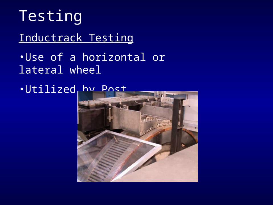
TestingInductrack Testing
•Use of a horizontal or lateral wheel
•Utilized by Post

Theories•Disk Method
•Wheel Method
•Tractor Tread Method
•Paddle Wheel Method

StandardsTable of standards used by the Low-Speed Urban Maglev Program
Will be used for concepts to keep in mind
Max. Speed 160 km/hr Max Jerk 2.5 m/s3 Throughput 12000/hr/direction Inside Noise Level < 67 dB Max Acceleration 1.6 m/s2 DC Mag. Field in Car < 5 Gauss Min Curve Radius 18.3 m (60 ft.) Availability > 99.99% Max Grade 10% Ride Quality ISO 2631 (1987)

PatentsRichard F. PostMagnetic Levitation System for Moving ObjectsU.S. Patent 5,722,326March 3, 1998
Richard F. PostInductrack Magnet ConfigurationU.S. Patent 6,633,217 B2October 14, 2003
Richard F. PostInductrack ConfigurationU.S. Patent 629,503 B2October 7, 2003
Richard F. PostLaminated Track Design for Inductrack Maglev SystemU.S. Patent Pending US 2003/0112105 A1June 19, 2003
Coffey; Howard T.Propulsion and stabilization for magnetically levitated vehiclesU.S. Patent 5,222,436June 29, 2003
Coffey; Howard T.Magnetic Levitation configuration incorperating levitation, guidance and linear synchronous motor U.S. Patent 5,253,592October 19, 1993
Levi;Enrico; Zabar;Zivan; Air cored, linear induction motor for magnetically levitated systems U.S. Patent 5,270,593November 10, 1992
Lamb; Karl J. ; Merrill; Toby ; Gossage; Scott D. ; Sparks; Michael T. ;Barrett; Michael S. U.S. Patent 6,510,799January 28, 2003

ScheduleTentative schedule:
Weeks 1 – 4 Development and testing of tracksWeeks 5 – 8 Development of a propulsion methodWeeks 9 – 10 Integration of the propulsion and the
InductrackWeeks 11 – 13 Propulsion ControlsWeek 14 Finish Loose Ends
Based on progress, meetings with Dr. Anakwa will determine the direction the project will take after each step

Parts and Equipment
40 - 1/2” NdFeB, Grade 38 Cubes $90.00
40 - 1/4” NdFeB, Grade 38 Cubes $14.40
Litz-wire Bulks, Copper Sheets, Aluminum Sheets, Wheels, Conductive balls, and Electromangets
Cart/Train non inductive materials and CNC router machine time provided by Midwestern Wood Products Co.

Resources
•Many Documents by Richard F. Post (LLNL)
•General Conversation with Richard F. Post (LLNL)
•General Conversation with Phil Jeter (General Atomics)
•General Conversation with Hal Marker (Litz-wire)
•General Converastion with Dr. Irwin (Bradley University)