bp texas city explosion interim report
DESCRIPTION
Investigation report of BP Texas City refinery explosion. Report provides description of accident causals together with recommendations.TRANSCRIPT

FATAL ACCIDENT INVESTIGATION
REPORT
Isomerization Unit Explosion Interim Report
Texas City, Texas, USA
Date of Incident: March 23, 2005 Date of Report: May 12, 2005 Approved for Issue John Mogford

FATAL ACCIDENT INVESTIGATION REPORT
2
Executive Summary During the startup of the Isomerization Unit on Wednesday, March 23, 2005, explosions and fires occurred, killing fifteen and harming over 170 persons in the Texas City Refinery, operated by BP Products North America Inc. An Investigation Team was established immediately to investigate the incident, and evidence gathering was conducted jointly with the involved contractors (Jacobs Engineering, GE, and Fluor-Daniel). This interim report presents a preliminary analysis of the events leading up to the incident, identifies provisional critical factors, and makes recommendations to prevent recurrence. Although analysis is ongoing, it is felt beneficial to issue this report to ensure that maximum benefit is gained in terms of learning and prevention of recurrence. All evidence collected by the Investigation Team has been shared with the Occupational Safety and Health Administration (OSHA) and Chemical Safety Board (CSB). The incident involved the Raffinate Splitter (a distillation column that separates gasoline blending components) and the Blowdown Drum & Stack (F-20), designed to handle pressure relief and vent streams. The investigation identified that the explosions were most likely the result of ignition of hydrocarbon vapors released from F-20. These hydrocarbons were discharged when the pressure in the Splitter column increased rapidly and exceeded the set pressure of the overhead line relief valves. F-20 was unable to handle all the fluids, and vapors and liquid discharged from the top of the Stack. An unknown ignition source from the numerous potential ones present in the uncontrolled area (vehicles, trailers, etc.) ignited the resulting vapor cloud. Many of the injured or killed were congregated in or around temporary trailers used for supporting turnaround work on a nearby process unit. A possibility that hydrocarbon vapors spread through the sewer system were the source of the initial ignition cannot yet be fully discounted. Four potential scenarios could have produced this excess pressure:
(a) Vapor pressure of hydrocarbons due to excessive thermal energy (b) Steam generation from the presence of water at high temperature (c) Non-condensables (nitrogen) remaining from the tightness testing (d) Improper feed to the unit or introduction of “foreign material” in the feed (e) A combination of the above.
Several steps in the startup procedure were omitted or not followed. The Board Operator overfilled the Splitter and overheated its contents without understanding that the very high liquid level and base temperature would contribute to a high pressure. The outside operators used local practices to control unit pressure instead of a purpose-built system, without understanding the possible implications.

FATAL ACCIDENT INVESTIGATION REPORT
3
Supervisory staff did not verify that the correct procedure was being used or followed, and were absent from the unit during shift relief, and key stages of the startup. There was a lack of clarity around who was supervising the startup. Although the startup procedure was not up-to-date, if the procedure had been followed, or if one of several possible interventions had been made earlier, this incident would not have happened. Several trailers were located within 150 ft of F-20 and acted as a congregating point for non-operations personnel. Management of Change processes did not consider the possibility of significant release of hydrocarbons at the stack. This potential had not been considered in any previous site study. The injured were not notified in advance of the impending startup, or alerted when hydrocarbons were discharged from the stack, which led to them remaining in place and being exposed to the hazard. Both the trailer location and not alerting personnel increased the severity of the incident. The following provisional critical factors have been identified based upon the analysis performed to date: Loss of Containment Actions taken or not taken led to over-pressurization and pressure relief of the Raffinate Splitter. Hydrocarbon flow to the Blowdown Drum & Stack (F-20), vented to atmosphere, causing a vapor cloud, which was ignited by an unknown source. Raffinate Splitter Startup Procedures and Application of Skills and Knowledge Failure to follow the startup procedure contributed to the loss of process control. Key individuals (management and operators) displayed lack of applied skills and knowledge and there was a lack of supervisory presence and oversight during this startup. Control of Work and Trailer Siting Numerous personnel working elsewhere in the refinery were too close to the hazard at the Blowdown Drum & Stack (F-20) during the startup operation. They were congregated in and around temporary trailers and were neither evacuated nor alerted. Design and Engineering of Blowdown Drum & Stack Blowdown stacks have been recognized as potentially hazardous for this type of service, and the industry has moved more towards closed relief systems to flare. Opportunities to tie the Splitter relief lines into a flare system were not taken, and the site continued to use F-20 as part of the relief and venting system for the Raffinate Splitter. The use of a flare system would have reduced the severity of the incident. A number of preliminary recommendations have been made to address these critical factors for the Isomerization Unit. These recommendations relate to applied knowledge and skills of leadership, supervision, and workforce, operating procedures and their observance, control of work, trailer siting, and design and engineering of relief systems, including eliminating F-20.

FATAL ACCIDENT INVESTIGATION REPORT
4
The main work outstanding at the time of publication of this interim report is:
• Analysis of process stream samples • Testing of process instrumentation and equipment, such as relief valves • Internal inspection of the Raffinate Splitter and F-20 • Modeling of the process and explosion
A final investigation report will be produced when these are completed.

FATAL ACCIDENT INVESTIGATION REPORT
5
TABLE OF CONTENTS
Page Executive Summary.......................................................................................... 2 Main Body
1. Introduction ............................................................................................ 6 2. Background ............................................................................................ 7 3. Description of the Incident .................................................................... 9
3.1 Sequence of Events Leading up to the Incident ............................... 9 3.2 The Incident ................................................................................... 11
4. Evidence ............................................................................................... 12 4.1 Site Inspections.............................................................................. 12 4.2 Witnesses....................................................................................... 13 4.3 Samples ......................................................................................... 13 4.4 Equipment Testing ......................................................................... 13 4.5 Documentation .............................................................................. 14 4.6 Additional Evidence........................................................................ 14
5. Analysis (System Causes)................................................................... 15 5.1 Loss of Containment - Potential Scenarios .................................... 15 5.2 Operating Procedures .................................................................... 17 5.3 Trailers ........................................................................................... 19 5.4 Plant Design, Engineering and Operability..................................... 20
6. Provisional Critical Factors................................................................. 23 7. Proposals for Corrective Actions .........................................................26
7.1 Loss of Containment ..................................................................... 26 7.2 People and Procedures ................................................................. 26 7.3 Control of Work and Trailer Siting.................................................. 27 7.4 Design and Engineering................................................................. 28
Appendices
Appendix 1 ................................................................................................. 30 Appendix 2 ................................................................................................ 32 Appendix 3 ................................................................................................. 33 Appendix 4 ................................................................................................ 34 Appendix 5 ................................................................................................. 35 Appendix 6 ................................................................................................ 39 Appendix 7 ................................................................................................. 40 Appendix 8 ................................................................................................. 41 Appendix 9 ................................................................................................. 42 Appendix 10 .............................................................................................. 43 Appendix 11 ............................................................................................... 44 Appendix 12 .............................................................................................. 45
Appendix 13................................................................................................ 46

FATAL ACCIDENT INVESTIGATION REPORT
6
1. INTRODUCTION During the startup of the Isomerization Unit (ISOM) on Wednesday, March 23, 2005 following a temporary outage, explosions and fires occurred which killed fifteen and harmed over 170 persons in the BP Texas City Refinery, Texas, owned and operated by BP Products North America. The site was secured and a Fatality Investigation Team was established immediately on March 24 to investigate the circumstances surrounding the incident, determine the root causes, make recommendations to prevent a recurrence, and identify lessons learned. Terms of reference for the investigation are detailed in Appendix 1. This interim report presents an analysis of the events leading up to the incident, identifies a number of provisional critical factors for the incident, and makes recommendations to prevent a recurrence. Although it is recognized that the evidence and analysis is not yet complete, it is felt beneficial to issue this report to ensure that the organization gains the maximum benefit in terms of learning and prevention of recurrence. A final comprehensive investigation report will be produced when these tasks are complete. The evidence gathering started immediately following the emergency response by the Texas City Site Incident Management Team (IMT). A joint team of BP and contractor (Jacobs Engineering (parent company of JE Merit), GE, and Fluor-Daniel) staff was assembled within the first 24 hours following the accident, with interviews commencing on March 24. At the request of BP Products North America Inc., a BP group executive was assigned to lead the investigation and another three individuals from outside of the Refining Business Segment were assigned to the team. Three union and three salaried Texas City employees completed the team. The BP Investigation Team officially took over the evidence gathering responsibility from the IMT on March 26. The preliminary investigation was performed over 5 weeks at the BP Texas City site. It included visits to the incident site, interviewing witnesses, and collecting documents and records. Photographs were taken to assist in the investigation. The hard drive from the process control system was secured. Samples were collected for chemical analysis and third party specialist companies were retained to document the explosion debris and effects, and to model the nature and extent of the explosion. All of the evidence gathered has been shared with the US Chemical Safety Board (CSB) and the Occupational Safety and Health Administration (OSHA). The main work outstanding at the time of publication of this interim report is:
• Analysis of various process stream samples • Testing of process instrumentation and equipment, such as relief valves • Internal inspection of the Raffinate Splitter (Splitter) and Blowdown Drum &
Stack • Modeling of the process and explosion

FATAL ACCIDENT INVESTIGATION REPORT
7
2. BACKGROUND The Texas City Refinery is BP’s largest and most complex oil refinery with a rated capacity of 460,000 barrels per day (bpd) and an ability to produce about 11 million gallons of gasoline a day. It also produces jet fuels, diesel fuels and chemical feed stocks. The refinery has 30 process units spread over a 1,200 acre site and employs about 1,600 permanent BP staff. At the time of the incident there were approximately 800 additional contractor staff on site for significant turnaround work. The incident occurred on the ISOM and involved the Splitter, and Blowdown Drum & Stack. The ISOM converts low octane blending feeds into higher octane components for blending to unleaded regular gasoline. The unit has four sections including the Splitter, which takes a non-aromatics stream from the Aromatics Recovery Unit (ARU) and fractionates it into light and heavy components. Many of those injured or killed were congregated in or around temporary trailers used for supporting turnaround work taking place on the nearby Ultracracker unit. Raffinate Splitter The Splitter started life in 1976 as the Heavy Ultraformate (HUF) Fractionator, as part of Ultraformer No.1, built to recover xylene from Ultraformer product streams. In 1985, the Ultraformer was converted to a naphtha isomerization unit to provide additional octane needed for the government's lead phase-out program, and the HUF Fractionator was converted to its current use. In 1987, the ISOM was again modified, and the Splitter underwent minor changes to improve its ability to split light and heavy raffinate. The resulting Splitter is a single fractionating column, 164ft tall with 70 distillation trays (at 2ft spacing numbered from the top), feed surge drum, fired heater reboiler, and fin fan overhead condenser. It has an approximate volume of 3700 barrels, and processes up to 45,000 bpd of raffinate from the ARU. About 40% of the total raffinate fed to the unit is recovered overhead as C5 / C6 light raffinate and is used as feed stock for the ISOM. The remaining heavy raffinate is used in JP-4 jet fuel. The Splitter may be run in conjunction with the ISOM or independently when the ISOM is shutdown. Blowdown System The purpose of the blowdown system is to receive, quench, and dispose of hot liquid and/or hydrocarbon vapors from the ISOM relief, vent, and pumpout systems during upsets or shutdowns. The blowdown system consists of relief pipework headers, two from other parts of the ISOM plus one from the Splitter, the Blowdown Drum & Stack (F-20), and Pumpout Pump. Vapors are dispersed from the top of the stack and liquids flow out of the drum through a gooseneck into the site’s closed sewer system. F-20, a vertical drum of 10ft diameter with a 113ft high stack, was commissioned in the 1950’s and has an approximate volume of 390 bbls. Simplified process flow diagrams (PFD) of the Splitter and Blowdown System can be found in Appendices 2 & 3.

FATAL ACCIDENT INVESTIGATION REPORT
8
History of the Isomerization Unit There have been a number of events on the ISOM involving hydrocarbon leaks, vapor releases, and/or fires. Interviewees made references to several previous incidents, and the Investigation Team identified the following from document searches:
• 3 fires, one each in 1986, 1987 and October 1988. • April, 1992 explosion and fire resulting in one fatality. • 1994 incident involving vapors from F-20 stack during startup of Preflash
Tower and Deisohexanizer (DIH) Tower. • January, 1999 involving venting an estimated 13,000 lbs of hydrocarbons
through F-20 from the Penex Reactor. • April, 1999 fire during maintenance. • February, 2002 Scrubber tower relief valve lifted releasing 30 barrels. • November, 2002 runaway thermal excursion of the Penex Reactor. • January, 2003 venting of liquid hydrocarbons to F-20. • January, 2003 fire involving hydrogen from a leaking bleeder. • At least 2 occurrences where the Splitter pressure exceeded 40 psig during
startup (exceeding the RV settings), since the Splitter was re-rated in 2003 from 70 psig to 40 psig.
• February, 2005 incident with liquid hydrocarbons leaking to the sewer during the de-inventory of the Splitter.
• March, 2005 fire (bleeder on D-300 or 301 with bull plug missing). Incident records before 1999 were difficult to locate apart from logs from the site Fire Department. The severity of less serious incidents was difficult to assess. The incident investigation records around these incidents reviewed appear less than complete with recommendations of corrective actions focusing on training and procedures with little examination of the adequacy of operating philosophy. Temporary Offices Trailers are primarily used as temporary offices at the Texas City Refinery to support contract workers involved in project work and turnarounds. They are sited under a Management of Change (MoC) procedural control process. When a trailer is to be sited within 350 feet of a process unit there is specific requirement that a Facility Siting Analysis be performed. Several trailers involved in the incident were located between two operating units, the ISOM and the Naphtha Desulfurization Unit (NDU). They were required for a turnaround on the Ultracracker Unit across the road to the north of the ISOM. A normally unoccupied building for storing catalyst is also in this area. When the site completed a comprehensive study of occupied buildings in 1997, this location for siting trailers was not identified as an area of concern. The closest trailer, a double wide J.E. Merit trailer, was located within 150ft of the base of the F-20, and is where most of the fatalities were located at the time of the explosion. The plot plan of the ISOM and surrounding areas is depicted in Appendix 4.

FATAL ACCIDENT INVESTIGATION REPORT
9
3. DESCRIPTION OF THE INCIDENT
3.1 Sequence of Events Leading up to the Incident A double-wide trailer for J.E. Merit was installed west of the ISOM on September 1, 2004. The MoC for the siting of this trailer was approved to proceed on October 6 (but was not approved for occupancy). The trailer was first occupied in late October/early November 2004. Subsequently several other trailers were installed west of the ISOM for the Ultracracker turnaround, including trailers for Contech (January 10, 2005), Timec (February 4), and Hahn & Clay (February 14). The MoC for the siting of these trailers was approved for commission (i.e. occupancy) on February 15. On February 21, 2005 the Splitter was shutdown for a temporary outage (caused by work on another part of the ISOM and ARU TAR), and steamed out to remove hydrocarbons from February 26 to 28. Condensate was drained from low point drains on March 14 in preparation for restarting the unit. Following pressuring with nitrogen at 22.5 psig for tightness testing, the Splitter was depressured on March 21. On night shift March 22/23, the step-up Shift Supervisor brought in cold feed to the Raffinate Splitter to establish levels in the Feed Drum (F-1101) and Column (E-1101), and to pack the Reboiler (B-1101) circulation loop. At shift relief the Column had 4 psig pressure and a 100% base level indication (100% is equivalent to approximately 10ft height in the 164ft tall column). On arrival at 06:00 hrs March 23, the day shift checked the unit line up, and at 09:21 hrs opened the 8 inch chain-operated vent valve, around the column overhead relief valves, dropping the column pressure from 4 psig to nominally atmospheric pressure. Reboiler circulation started at 09:41 hrs, and feed was re-introduced at 09:52 hrs to the Splitter at a rate of 20,000 barrels per day (bpd). After stroking the Heavy Raffinate product control valve (LCV-5100) to verify the line up to tankage, this valve was closed. After this the flow meter indicated a Heavy Raffinate product flow of 3000 to 4700 bpd despite the closed control valve, it is believed to be a zero error on the meter which may have misled the board operator into thinking that he had some outflow. The absence of heat exchange between the Heavy Raffinate and feed at the Feed/Bottoms Exchangers (C-1104A/B) in this time confirms the lack of any Heavy Raffinate flow. At approximately 10:00 hrs, two main burners were lit in the Reboiler fired heater (B-1101). Shortly afterwards, the Day Shift Supervisor for the ISOM left the site due to a personal family matter. Two additional main burners were lit in the heater at 11:17 hrs, and the Splitter bottoms temperature continued to rise at approximately 75˚F per hour. The Reflux Drum (F-1102) level was checked by the operators as the level transmitter continued to show 0%. Only vapor emerged from the bottom tap of the level gauge.

FATAL ACCIDENT INVESTIGATION REPORT
10
By 12:40 hrs, the Splitter pressure had steadily climbed to 33 psig (normal operating pressure is about 20 psig), and the base temperature had reached 302˚F (normal operating temperature is 280-290˚F). At this point the operators opened the 8 inch chain-operated vent valve for the second time. An operator reported seeing vapors that looked like steam venting from the top of the Blowdown Drum & Stack (F-20). After approximately 10 minutes the valve was closed, and by 12:55 hrs the pressure had fallen to 22.6 psig. A safety meeting was held in the Control Room for the ISOM/NDU/AU2 units, close to the control board for the ISOM from approximately 12:45-13:00 hrs, and was attended by the area Superintendents, Shift Supervisors and approximately 15 other operations and maintenance personnel. At 12:58 hrs the Heavy Raffinate product flow to tankage was started for the first time and by 13:09 hrs had stabilized at 28,000 bpd. This Heavy Raffinate stream exchanges heat with the incoming feed to the unit in the Feed/Bottoms Exchangers (C-1104A/B). At 13:01 hrs the feed preheat was 126˚F, and had risen to 260˚F by 13:10 hrs. Shortly after 13:00 hrs the off-site Day Shift Supervisor telephoned the ISOM Satellite Control Room from outside the Refinery, and, upon hearing of the pressure, suggested opening the 1½ inch vent valve, around the Reflux Drum relief valve, to vent nitrogen. This vent valve was opened and by 13:13 hrs the pressure in the Splitter had fallen to 20.5 psig. The inlet feedrate to the column remained at approximately 20,000 bpd throughout this period. Raffinate Splitter Level As stated previously, the night shift on March 22/23 packed the Raffinate Splitter with feed and left the column base level at 100% (of the level transmitter range). The day shift re-introduced feed at 09:52 hrs at a feedrate of 20,000 bpd. The Heavy Raffinate product control valve (LCV-5100) was opened at 12:41 hrs, and a Heavy Raffinate outflow registered at 12:58. Up to this point approximately 2,500 barrels had been added to the column since 09:52 hrs. By 13:09 hrs the Heavy Raffinate outflow at 28,000 bpd exceeded the incoming feedrate, but in this short period this would only have reduced the volume in the column by a small amount. Therefore, with a higher level (100%) than called for in the Splitter column to begin with, a further 3 hours of feed at 20,000 bpd (i.e. 2,500 barrels) was added to the column with no outflow. This resulted in the liquid level within the column reaching tray 13 level (137ft high vs. normal operating level in range of 6-7ft) at approximately 12:45 hrs. At this level, 57 of the 70 trays within the column are flooded, and the feed inlet at tray 31 is submerged. Under these circumstances the Splitter would not perform as a conventional distillation column.
FATAL ACCIDENT INVESTIGATION REPORT
11
Temperature readings at several trays within the column support a very high level in the column. At 11:30 hrs the temperature profiles of the Splitter feed and at tray 33 were the same, suggesting that the liquid level had reached tray 33. At 12:00 hrs, the temperature profiles suggest that the liquid level had reached tray 27. The detailed timeline of the incident is shown in Appendix 5, while graphs depicting the key process parameters are shown in Appendices 6 and 7. 3.2 The Incident An Ultracracker turnaround meeting had been called in the J.E. Merit trailer, and attendees had started arriving. Heavy Raffinate outflow from the Splitter had commenced at 12:58. At 13:13 hrs the Raffinate Splitter pressure was 20.5 psig, and started to increase rapidly. By 13:15 hrs the pressure peaked at 63 psig, and witnesses confirmed that the column overhead relief valves (with set points of 40, 41 and 42 psig) had opened to feed directly into F-20 through a 14” header. At this point the operators reduced fuel gas firing to the heater, blocked in the main burners, and at 13:19 hrs shut the Fuel Gas control valve at both the main and satellite control boards. The outside operators also started the Reflux Pump (J-1102A) at 13:17 hrs. The indicated reflux flowrate went off scale in excess of 35,700 bpd. The second Reflux Pump (J-1102) was also started at 13:19 hrs. At about this time there were radio messages from at least two witnesses, who saw vapors and liquid emerging approximately 20 ft above the top of the stack ‘like a geyser’ and running down and pooling around the base of F-20. Vapors were seen evaporating from the liquid pool. The F-20 high level alarm (LAH-5020) alarmed for the first time at 13:20 hrs. Alerted by the radio messages and shouting of at least one eye witness, several personnel in the area of the ISOM were able to leave the immediate vicinity before the vapors ignited. Several witnesses described two or more explosions; the first minor explosion(s) followed rapidly by a louder, more powerful blast at approximately 13:20 hrs. The explosion severely damaged the J.E. Merit and other trailers on the west side of the ISOM, and resulted in 15 fatalities and over 170 individuals harmed. The blast resulted in damage to the ISOM, causing a number of secondary hydrocarbon releases and fires. The Site Emergency Response Team responded and immediately mounted a search and rescue operation. Mutual Aid and Lifeflight resources were requested and mobilized by 13:45 hrs. The fires were brought under control after 2 hours, and injured personnel had been treated and/or transported to local hospitals, allowing ambulances and Lifeflight resources to be stood down by 16:44 hrs. However, one body was not found until approximately 23:00 hrs, having been buried under debris. The detailed timeline of the Emergency Response phase of the incident is shown in Appendix 8.

FATAL ACCIDENT INVESTIGATION REPORT
12
4. EVIDENCE The evidence gathering started immediately following the emergency response by the IMT. The evidence summarized below are the data on which the Investigation Team has established the facts surrounding the incident, the critical events and conditions, and the subsequent analysis which will ultimately lead to the conclusions and corrective actions to prevent recurrence. The first photographs were taken within minutes of the incident and continued throughout the emergency response. The hard drive containing the process control information was powered down immediately following the emergency response and secured on March 24. The board operator log book and shift supervisor log books were also secured shortly after the emergency response by the IMT. However, the procedure in use on the ISOM at the time of the incident was not secured until April 2. The evidence gathered has been shared by the BP Investigation Team with the Occupational Safety and Health Administration (OSHA) and the US Chemical Safety Board (CSB). 4.1 Site Inspections The Investigation Team toured the incident scene perimeter for the first time on March 26, 2005. Because of the hazards posed on the site, access to the ISOM was controlled by OSHA and further restricted due to the court imposed restraining order. On April 1, the Investigation Team was granted access to areas of the ISOM by OSHA. However, there was no access to the area between the ISOM and the Naphtha Desulphurization Unit (NDU) where the trailers were located. Key observations were:
• The valve on the middle line of 3 lines feeding the Column (E-1101) appeared to be in the open position. The valve on the top feed line was subsequently confirmed as one quarter open while the valve on the bottom line was closed.
• The 3 psig vent line was blocked in downstream of the control valve. • Position of 8 inch chain-operated vent valve to F-20 was closed. • The explosion damage on the ISOM was mainly on the west side of the unit. • The block valve on the reflux drum 1½ inch vent to F-20 was closed.

FATAL ACCIDENT INVESTIGATION REPORT
13
On April 6, the balance of the Investigation Team was granted access to the incident scene. Key observations were:
• Detailed fire and explosion damage on the ISOM. • Fire damage around F-20 including spalling of reinforced concrete
construction and concrete pad. • Observed that valve position on 14 inch relief line from the Splitter to F-20
and the 6 inch F-20 outlet line was open. • Confirmed earlier observation that the 3 psig line was blocked in downstream
of the control valve. • Confirmed earlier observation that the 8 inch chain-operated vent valve was
closed. • Confirmed earlier observation of the valve positions on feed lines to the
Splitter • Damaged trailers in the area between the ISOM and the NDU. • Observed corroded liquid disposal line from F-20 to the sewer system.
Subsequently the Investigation Team made multiple visits to the site to observe sampling of process vessels and lines, as well as to observe the damage to the process sewer. Third party companies were retained to document and catalog the explosion debris and effects of the blast, model the nature and extent of the explosion, and have been given wide access to the site. 4.2 Witnesses Initial witness interviews were organized by the IMT and commenced on March 24. The interview portion of the evidence gathering phase of the investigation was concluded on April 28. Additional interviews may be conducted if new evidence suggests a need for further inquiry. During the course of the investigation to date, the team has conducted 73 interviews with 55 (50 BP employees and 5 Contractors) people. The interviews were conducted in the presence of a court reporter. 4.3 Samples Extensive sampling of process streams was undertaken after April 10. A full list is attached in Appendix 9. All samples will be analyzed by a certified independent laboratory. 4.4 Equipment Testing At the time of this Interim Report, it has not yet been possible to de-inventory the Splitter and make it safe for detailed analysis. As a result, the testing and inspection of items of equipment remains outstanding. See Appendix 10 for full details.
FATAL ACCIDENT INVESTIGATION REPORT
14
4.5 Documentation Documents, procedures, records and engineering drawings pertinent to the incident were identified immediately after the event. In particular, copies of the following documents were reviewed as evidence:
• Operations log books (Shift Supervisor log, Board Operator log) • PI records for the past 5 years and DCS records for 15 days prior to the accident • Startup Procedure (for March 23, 2005) • Trailer Siting MoC • Witness statements and transcripts
Immediately following the incident, the startup procedure in use at the time of the incident was believed to be in the heavily damaged satellite control room. However, on April 2 the procedure was handed to the investigation team by the Shift Supervisor assigned to the ISOM on the day of the incident. Documentation was relatively easy to access and generally complete. A list of documentation reviewed is included in Appendix 11. A single comprehensive Safety Critical Equipment (SCE) Register (a.k.a. Register of Safety Related Devices) containing all safety critical equipment on the ISOM does not exist. Some of these data were available from multiple sources. A detailed chronology of the events leading up to the incident was compiled, based upon review of the PI and Honeywell DCS records, and the Operations log books (see Appendix 5). Interviews of the night and day shift operators and supervision provided clarification. A separate chronology of the emergency response has been prepared based upon the Emergency Response Team (ERT) log (Appendix 8). This was supplemented by interviews of the first responders, who provided information on the location of casualties, and the circumstances surrounding the secondary fires. 4.6 Additional Evidence BP has requested that OSHA and the CSB secure evidence for further analysis related to process equipment in a timely and efficient manner. This evidence includes control equipment and instrumentation to be tested; the debris pile west of the ISOM; and potential ignition sources. Subsequently the investigation team intends to reconvene, following efforts by Operations personnel to remove hydrocarbon inventories in order to make the unit safe. Team members will then conduct internal inspections of the vessels.

FATAL ACCIDENT INVESTIGATION REPORT
15
5. ANALYSIS (SYSTEM CAUSES) 5.1 Loss of Containment - Potential Scenarios The preliminary investigation identified that the explosions were most likely the result of ignition of hydrocarbon vapors released from the Blowdown Drum & Stack. These hydrocarbons were discharged when the pressure in the Raffinate Splitter column increased rapidly at 13:13 hrs and exceeded the set pressure of the overhead line relief valves (RV-1001A/B/C). Four potential sources that could have produced this excess pressure were identified:
(a) Vapor pressure of hydrocarbons due to excessive thermal energy (b) Steam generation from the presence of water at high temperature (c) Non-condensables (nitrogen) remaining from the tightness testing (d) Improper feed to the unit or introduction of “foreign material” in the feed (e) Any combination of the above
A second possibility that hydrocarbon vapors were spread through the sewer system and became the source of the initial ignition cannot be discounted at this time. F-20 has a drain connection to the sewers, and liquid hydrocarbons could have passed from an Oily Water Separator into a Dry Weather Sump, and then into storm water sewers near the trailers. The Investigation Team is undertaking a detailed analysis to understand the circumstances pertaining to each of these possible energy sources, in order to be able to verify or discount each scenario. This detailed analysis which is ongoing is discussed below: 5.1.1(a) Vapor Pressure The high pressure in the Raffinate Splitter could have been due to the vapor pressure of the column contents at high temperature. Immediately prior to the rapid increase in pressure, the column base temperature was stable at 302˚F (27˚F above the temperature specified in the startup procedure). The high liquid level in the Splitter and relatively cold feed at only 126˚F could have allowed a high base temperature to be masked by colder hydrocarbon above. Detailed dynamic process modeling of the Splitter will be necessary to determine if hydrocarbon vapor pressure alone can account for the high pressure experienced, and also the effect from the rapidly increasing feed preheat.
FATAL ACCIDENT INVESTIGATION REPORT
16
5.1.1(b) Steam Generation The presence of water during the startup of the Raffinate Splitter could have liberated steam, as temperatures increased, resulting in the rapid pressure increase. The Splitter was steamed out in February to gas free the unit. Although water was drained from a number of low points prior to re-starting the unit, some condensate could have remained in the unit. An early flow of Heavy Raffinate to tankage would be expected to remove any water, but on this occasion Heavy Raffinate flow to tankage was not established until 12:58 hrs. Internal inspection will be necessary to verify if water could have collected in sections of equipment without drain points. 5.1.1(c) Nitrogen The Raffinate Splitter was pressure tested for tightness with nitrogen at approximately 22.5 psig. Some residual nitrogen would have remained after depressuring, and may have been concentrated in the column overhead reflux system due to the high liquid level in the Splitter. As temperatures were raised to distill vapors overhead, the presence of nitrogen could have inhibited the vapors from reaching the cold surface area of the Overhead Condensers (C-1101), and condensing to provide reflux. Without condensing capacity the column pressure would rise. Any nitrogen present could also exert its partial pressure, adding to the column total pressure. 5.1.1(d) Improper Feed The high pressure experienced in the Raffinate Splitter could have been caused by an unusually light hydrocarbon feed to the unit, or any contamination of the feed stream with foreign materials. Samples of the feed stream have been taken, and will be tested by a certified independent laboratory. The results from testing these feed samples have not yet been received. 5.1.2 Sewers There are indications that hydrocarbon liquids were discharged to the refinery sewer system. Several high hydrocarbon level alarms occurred in the Diversion Box and Dry Weather Sump west of the ISOM after the Overhead RVs lifted at approximately 13:14 hrs. Spreading hydrocarbons to adjacent areas via the sewer system may have created another possible source of flammable vapors near the trailers. Further detailed analyses are required to determine if this contributed to the incident.
FATAL ACCIDENT INVESTIGATION REPORT
17
5.1.3 Scenario Conclusion Further detailed analysis of the above scenarios will be necessary before the Investigation Team can determine which scenario is supported by the available evidence. A number of third party specialist companies have been retained to analyze the incident through modeling of the process and the explosion. Further process modeling of the unit will take into account the high liquid level in the Splitter. It is anticipated that these models, analysis of samples and internal vessel inspections may assist in determining which scenario occurred. 5.2 Operating Procedures There are two Standard Operating Procedures (SOP) for startup of the Raffinate Splitter; “Raffinate Unit Startup Following a TAR” (SOP 201.0), and “Normal Raffinate Startup Procedure Following a Temporary Outage” (SOP 201.1). Given that nitrogen was used to pressure test the unit for tightness, SOP 201.0 (Startup after TAR) should have been followed for this particular startup. SOP 201.0 was last updated on October 1, 2003, and the Superintendent confirmed in the last annual certification (early March 2005) that all ISOM unit operating procedures were current and accurate. However, on January 31, 2003 the Overhead RVs (RV-1001A/B/C) were de-rated from 70 psig to 40/41/42 psig respectively and this change was not reflected in SOP 201.0, although most of the operators were aware of the change. This de-rating also affects the pressure at which nitrogen tightness testing can take place, which is incorrectly stated as 50 psig in SOP 201.0, i.e., above the new set pressure for the RVs. SOP 201.0 addresses the hazards of water and non-condensables (nitrogen) in the unit during startup, although the procedure could be improved by placing greater emphasis on these hazards and troubleshooting if problems arise, especially since the normal operation would not use the 3 psig vent system. The Day Shift Supervisor provided the Outside Operators with SOP 201.0 (Startup after TAR) to record completed steps in the procedure. However the Board Operator stated that he printed off SOP 201.1 (Startup after Temporary Outage) on March 23 and made little reference to the document. An inexperienced Outside Operator was instructed by the Day Shift Supervisor to sign off individual steps in SOP 201.0 without personally witnessing every step. Several steps were omitted or a different action taken, as follows:

FATAL ACCIDENT INVESTIGATION REPORT
18
• Night shift did not sign off any steps completed • Review of procedure with all crew members not done (Step B.12) • Nitrogen tightness test was conducted at 22.5 psig vs. 50 psig in procedure
(numerous steps in Section C) in line with the new re-rated RV settings • Line up and open 3# Vent System not done (Steps F.17/18) • Eight (8) inch Vent valve around Overhead RVs was opened to control
pressure vs. 3# Vent System in procedure (Steps F.18, H.15) • One and a half (1½) inch Vent valve around Reflux Drum RV was opened to
control pressure vs. 3# Vent System in procedure (Steps F.18, H.15) • Night shift put 100% level in Splitter vs. 50% in procedure (Step G.16) • Day shift filled Splitter above 100% level vs. 50% in procedure (Step G.16),
and subsequently not setting the automatic level control • Day shift did not establish Heavy Raffinate rundown to tankage (Steps
G.15/16) until just before incident • Splitter temperatures raised at approx. 75˚F/hr vs. 50˚F/hr in procedure (Step
H.6) • Splitter base temperature raised to 302˚F vs. 275˚F in procedure (Step H.6)
The Day Shift Supervisor for the ISOM outage arrived late for his shift and thus did not receive any handover information from the Night Shift Supervisor (who was a stepped up Process Technician), and the duration and quality of pass down between the respective operators was inadequate. The Day Shift Board Operator received a partial handover as the startup procedure used by the step-up Night Shift Supervisor, who packed the Splitter, was in the satellite control room. The ISOM was staffed with a larger than normal operating contingent, with experienced and trained operators in place, although 3 of the operators training records were incomplete. The organization chart is shown in Appendix 12. The Superintendent (who was the Training Coordinator stepped up) was unaware that the Splitter was being started up, and it was not mentioned at the Shift Director’s morning meeting to indicate to those in proximity that the unit was to be started. At 10:47 hrs the Day Shift Supervisor left the site and it was not clear who was then in command of the operations. The crew believed it to be the stepped up operator, while the Superintendent and the absent Supervisor stated that they believed it was a Supervisor from the ARU turnaround who denies this. At 12:40 hrs when vapors, and again at 13:15 hrs when vapors and liquid, were reported discharging from F-20, the emergency warbler Evacuation Alarm at the ISOM was not sounded, as required by Texas City Site (TCS) HSE Policy A-7. The results of the weekly emergency alarm test were not recorded in the unit logbook as required by TCS HSE Policy A-7.

FATAL ACCIDENT INVESTIGATION REPORT
19
5.3 Trailers Trailers were being used as temporary offices between the ISOM and the Naphtha Desulfurization Unit (NDU) for contract staff. The area used for siting these trailers has been used for this purpose for many years. The facility has a procedure, including specific requirements, for siting trailers used as temporary offices. These procedures were developed in response to Section 29 Code of Federal Register (CFR) 1910.119, “Process Safety Management of Highly Hazardous Chemicals” (PSM) and API Recommended Practice 752 “Management of Hazards Associated with Location of Process Plant Buildings” [First Edition, May 1995]. API 752 provides guidance for identifying hazards that may affect process plant buildings and for managing risks related to those hazards. This Recommended Practice was developed as a tool to aid companies to comply with OSHA’s PSM requirements for addressing facility siting as part of a process hazards analysis (PHA). Normally occupied temporary buildings are within the scope of the Recommended Practice. Amoco developed a tool to implement the guidance detailed in API 752, entitled “Facility Siting Screening Workbook”. This workbook is the basis for the Texas City Refinery Management of Change (MOC) procedure requirements related to siting trailers. In addition to the MOC, the Refinery requires a hazard analysis when a trailer is to be located within 350 feet of a process unit. This analysis considers the types and quantities of hazardous material, potential ignition sources, and prevailing winds. The J.E. Merit trailer was sited in the area between the ISOM and the NDU in September, 2004 and was occupied in late October/early November. The additional trailers in this area were sited in January and February, 2005 in preparation for a turnaround on the Ultracracker Unit, which is across the road to the north of the ISOM. The J.E. Merit trailer was sited in the area before the MOC had been initiated. All of the trailers in this area were sited before the MOCs had been approved. While the site underwent a comprehensive study of occupied buildings in 1997, the area between the ISOM and the NDU was not identified as an area of concern for siting trailers. The practice of siting trailers in this area had become common place, as evidenced by the utility connections that had been provided. A 2002 facility siting study reviewed a trailer in the same area. The analysis included the number of people occupying the trailer, the duration of time the trailer would be there, types and quantities of hazardous material, and potential ignition sources. The analysis concluded the trailer siting was acceptable.

FATAL ACCIDENT INVESTIGATION REPORT
20
5.4 Plant Design, Engineering and Operability 5.4.1 Raffinate Splitter The Heavy Ultraformate Fractionator was modified to the Raffinate Splitter in the 1980’s, and modified again in 1998 to operate with a flooded reflux drum using heater firing rate to control pressure. This change required that the 3 psig vent system, used to vent non-condensables at startup, be isolated during normal operation. Subsequently use of the 8 inch vent valve to vent non-condensables and control pressure during startup became local practice instead of using the 3 psig vent system (as specified in the procedure). After inspection revealed thinning of the Splitter due to corrosion under insulation, the operating pressure was lowered. As a result, the three RV set points were reduced from 70 psig to 40, 41 and 42 psig respectively in March 2003. The relief valves were previously studied during a site-wide relief valve study in 1985, but neither study addressed the downstream Blowdown Drum & Stack. Another study by an external engineering agency stated that the RVs and stack were adequate, but full documentary evidence is unavailable. 5.4.2 Blowdown Drum & Stack Industry Design Standards The main industry standard for design, installation, and operation of blowdown systems is API Recommended Practice 521 “Guide for Pressure Relieving and Depressuring Systems”. It states (Page 32) that "In many situations, pressure-relief vapor streams may be safely discharged directly to the atmosphere if environmental regulations permit such discharges. This has been demonstrated by many years of safe operation with atmospheric releases from properly installed vapor pressure relief valves. The decision to discharge hydrocarbons or other flammable or hazardous vapors to the atmosphere requires careful attention to ensure that disposal can be accomplished without creating a potential hazard or causing other problems, such as the formation of flammable mixtures at grade level or on elevated structures, exposure of personnel to toxic vapors or corrosive chemicals, ignition of relief streams at the point of emission, excessive noise levels, and air pollution.” Amoco Design Standards Texas City Refinery was owned and operated by Amoco prior to the 1999 merger with BP,and was designed to Amoco and industry engineering codes and standards. In 1977 Amoco issued Process Safety Standard (PSS) No.6 “Flare, Blowdown, Pressure Relief, Vent, and Drain Systems for Process Units”. Although several subsequent revisions to PSS No.6 have been introduced, references to blowdown stacks did not change significantly. The 1986 revision of PSS No.6 stated “If still required, existing blowdown systems will be replaced with connections to depressure via another processing unit, a hydrocarbon-recovery system, or a flare when the size of the existing

FATAL ACCIDENT INVESTIGATION REPORT
21
facility is outgrown.” A later 1994 revision added “… or when major modifications are made to the existing facility.” The current version of PSS No.6 states that “…1) New blowdown stacks which discharge directly to the atmosphere are not permitted. 2) When the size of the existing facility is outgrown or when major modifications are made to the existing facility, existing blowdown systems which are still necessary should be replaced with connections to depressure via another processing unit, hydrocarbon-recovery system, or flare.” Amoco Corp. Engineering Specification A CV-PLT-DISP-E “Civil Plant Disposal Systems Engineering Specification” provides technical requirements for design of drain, vent, pumpout, blowdown, and sanitary sewer systems. It states that “Discharge of hot hydrocarbon (warmer than 1500F) shall be accomplished by releasing into a blowdown system where hydrocarbon is quenched with utility water. (a) Blowdown drum and stack shall be provided to discharge vapor to recovery system or flare and liquid into a process drainage system; (b) Blowdown systems shall not discharge directly to atmosphere.” F-20 Design The Blowdown Drum & Stack (F-20) was initially designed to handle hydrocarbons from one relief line during unit upsets or shutdowns. Since commissioning, design and operational changes to F-20 have added two additional inlet lines for dry and wet hydrocarbons from the ISOM. Despite this additional load, there does not appear to be a documented capacity analysis of the design. None of these changes over the years were considered a major modification triggering F-20’s disuse as recommended in PSS-6. In 1995 when a new flare system for the AU-2 unit was installed, and in 2002 when the NDU flare line was routed close to F-20, efficient opportunities for converting F-20 to an inherently safer alternative relief system were not taken. F-20 contains internal baffles to assist in disengaging any liquids from the hydrocarbon vapors. A steam connection is provided to the drum section below the baffles for extinguishing fires at the outlet from the stack. Any liquid hydrocarbons released to F-20 should pass through a “gooseneck” seal leg to a closed drain system, then to the West Oily Water Separator, where the oil is skimmed and pumped to slops. A pump (J-14A) is provided to pumpout liquids from F-20 during planned shutdowns. F-20 is equipped with a level glass to monitor the level and a high level alarm (LAH-5020), which will sound when F-20 is close to flowing over the top of the gooseneck. F-20 Maintenance and Mechanical Integrity Several examples of potential deficiencies in equipment maintenance and mechanical integrity on F-20 have been identified. Service water is supplied to F-20 for the purpose of cooling any hot process streams that may be diverted to the blowdown or pumpout systems during an upset or in a unit shutdown. This quenching system had been out of service for some time. Upon inspection in 2003, some of the baffles within F-20 had corroded and collapsed, and it was decided not to repair them.

FATAL ACCIDENT INVESTIGATION REPORT
22
Finally the 6 inch drain connection from the gooseneck to the closed drain system had a small leak. After the incident it was found cracked, but it is not known if this occurred before the explosion.

FATAL ACCIDENT INVESTIGATION REPORT
23
6. PROVISIONAL CRITICAL FACTORS The following provisional Critical Factors (events or conditions that if removed might eliminate, reduce the possibility of the event occurring or reduce the severity) have been identified based upon the analysis performed to date of the available evidence: CF-1. LOSS OF CONTAINMENT ACTIONS TAKEN OR NOT TAKEN LED TO OVERPRESSURIZATION
AND PRESSURE RELIEF OF THE RAFFINATE SPLITTER. HYDROCARBON FLOW TO THE BLOWDOWN DRUM & STACK (F-20), VENTED TO ATMOSPHERE, CAUSING A VAPOR CLOUD, WHICH WAS IGNITED BY AN UNKNOWN SOURCE.
The very high liquid level and base temperature contributed to the high Splitter
pressure. It is possible that the presence of water, nitrogen or incorrect feed were also key factors and caused the rapid increase and liquid carryover. Stopping feed, increasing offtake or reducing heat input earlier would have prevented the incident. Further understanding of the over-pressurization should be gained when the process and blast modeling and sample analyses are completed. Witnesses described the discharge of hydrocarbon liquid and vapors from the Blowdown Stack during the startup of the Splitter, the formation of a vapor cloud at ground level and subsequent ignition resulting in at least two explosions. Numerous potential ignition sources were present in the surrounding area (vehicles, trailers etc.) as the area was uncontrolled. Witness statements suggest that a truck engine could be the source of ignition but that is as yet unconfirmed.
CF-2. RAFFINATE SPLITTER STARTUP PROCEDURES AND APPLICATION OF KNOWLEDGE AND SKILLS FAILURE TO FOLLOW THE STARTUP PROCEDURE CONTRIBUTED
TO THE LOSS OF PROCESS CONTROL. KEY INDIVIDUALS (MANAGEMENT AND OPERATORS) DID NOT APPLY THEIR LEVEL OF SKILLS AND KNOWLEDGE AND THERE WAS A LACK OF SUPERVISORY PRESENCE AND OVERSIGHT DURING THIS STARTUP.
Several steps in the procedure were omitted and others deviated from. The Board Operator overfilled the Raffinate Splitter and overheated its contents without understanding the true status of the unit. The Outside Operators used local practices (e.g. 8 inch vent valve and the 1½ inch vent valve on the Reflux Drum instead of the 3 psig vent system to control unit pressure) without understanding the possible implications. Supervisory staff did not verify the correct procedure was being used or followed, and were absent from the unit during shift relief, pre-startup, and during heating and filling (startup).

FATAL ACCIDENT INVESTIGATION REPORT
24
The absence of key personnel and the behavior of supervision eroded the chain of command to the point that decision-making authority was unclear. Although the startup procedure was not up-to-date, if the procedure had been followed or if intervention had been made earlier, this incident would not have happened.
CF-3. CONTROL OF WORK AND TRAILER SITING
NUMEROUS PERSONNEL WORKING ELSEWHERE IN THE REFINERY WERE TOO CLOSE TO THE HAZARD AT THE BLOWDOWN DRUM & STACK (F-20) DURING THE STARTUP OPERATION. THEY WERE CONGREGATED IN AND AROUND TEMPORARY TRAILERS AND WERE NEITHER EVACUATED NOR ALERTED.
Several trailers were located west of the ISOM and acted as a congregating point for non-operations personnel working on the Ultracracker turnaround. This location was within 150 ft of the F-20, which had not been considered as a realistically potential hazardous source in any site study. Management of Change processes did not consider the possibility of significant release of hydrocarbons at the stack. The injured were not notified in advance of the impending startup, or when hydrocarbons were discharged from the stack. Plans could have been made to move them away before the startup operation, and the subsequent failure to sound the evacuation alarm at crucial times led to them remaining in place and being exposed to the hazard. Both the trailer location and not alerting personnel increased the severity of the incident.
CF-4. DESIGN AND ENGINEERING OF BLOWDOWN DRUM AND STACK THE USE OF BLOWDOWN DRUM & STACK (F-20) AS PART OF THE
RELIEF AND VENTING SYSTEM FOR THE RAFFINATE SPLITTER, AFTER SEVERAL DESIGN AND OPERATIONAL CHANGES OVER TIME, CLOSE TO UNCONTROLLED AREAS.
Blowdown stacks have been recognized as potentially hazardous for this service with the industry moving more towards closed relief systems to flare. Opportunities to tie the Splitter relief lines into a flare system were not taken when it could have been efficiently done in 1995 or 2002 as the true level of the hazard was not seen. Design and operational changes to the Splitter resulted in increased use of F-20. Incremental changes to F-20 included failing to replace the internal baffles, decommissioning the quench system, and adding additional inlets, possibly reducing its effectiveness. Several uncontrolled areas were close to F-20, e.g. roads, catalyst warehouse and trailer site, all within 150 ft. Conversion to a flare system would have reduced the severity of the incident.

FATAL ACCIDENT INVESTIGATION REPORT
25
When more evidence is available for analysis, the Immediate and System Causes will be further evaluated for each Critical Factor, using BP’s Comprehensive List of Causes methodology. However based on the critical factors identified and the causal analysis performed to date, the team believes that it can make recommendations in most areas.

FATAL ACCIDENT INVESTIGATION REPORT
26
7. PROPOSALS FOR CORRECTIVE ACTIONS The Investigation Team has identified recommendations to prevent a recurrence of this incident. These have been arranged in order of the critical factors identified previously: 7.1 Loss of Containment Any loss of containment related recommendations will be developed after the
process and blast modeling, and sample analyses have been analyzed. 7.2 People and Procedures
7.2.1 Leadership Actions
(a) Drive the Just Fair Culture with visible leadership especially in the matter of verification; ensure the work force fully delivers their accountabilities and self verify using job content audits for compliance; participate and communicate at all levels. Design new “diagonal slice” processes.
(b) Set clear and explicit Accountability and ‘Chain of Command organizational chart’ including geographical responsibility for Simultaneous Operations.
(c) Develop clear measurements for leading indicators of catastrophic incidents (e.g. process upsets, loss of containment, fires, High Potential incidents (HiPos), and indicators of major risk) vs. lagging indicators (i.e. reportables, spills, slips, trips and falls) and use to manage performance.
(d) Staffing plans for turnarounds and high workload periods must show explicit consideration for fatigue.
(e) Define and set expected behaviors, knowledge, skills and accountabilities, for leadership and supervision (Superintendents and Supervisors, applying to all Step-up personnel as well), including explicit expectations for sounding emergency alarms.
7.2.2 Supervision
Supervisors must be present at the shift relief on the unit to make sure that procedures are correct, signed off, and up to date. In addition, at startup and shutdowns, the Superintendent must be present at relief and the Supervisor must be onsite throughout the operation. They must maintain a chain of command at all times, any changes to which must be understood and approved by the Manufacturing Delivery Leader.

FATAL ACCIDENT INVESTIGATION REPORT
27
7.2.3 Operators
(a) Review all ISOM Training to ensure it is up to date and correct. Complete quality refresher training and assessment of operators on a routine basis (i.e. simulators for Board Operator and P/Ts) including process upset management, troubleshooting and explicit expectations for sounding emergency alarms.
(b) Complete a Human Factors Assessment of the Board Operator position and work environment to identify gaps and implement optimal work rotation. Assure the Board Operator maintains operational awareness through regular outside work.
(c) Establish sanctity of Control Room (i.e. remove distractions). 7.2.4 Procedures
(a) Improve practices for updating and following procedures (i.e. pre-job safety walkthroughs, signing off steps, Engineering involvement, shift relief). Supervision (Superintendents and Supervisors) must verify and audit that procedures are being followed, and be supported by Management conducting random verification audits.
(b) Conduct a thorough review of ISOM operating procedures to verify they are accurate and up to date; incorporate improved troubleshooting guidance; reflect operating practices; and are being followed.
(c) Modify startup and shut down procedures to include steps to notify personnel on all surrounding units and to evacuate all non essential personnel from the unit and surrounding area.
7.3 Control of Work & Trailer Siting 7.3.1 Facility Siting
Conduct a new, independent 3rd party led Facility Siting Study of the Texas City Site to determine all hazards to personnel on the ISOM Unit from normal and abnormal operations of the ISOM and surrounding process units, including catastrophic events. This study should address fire, explosion and toxic hazards to occupied buildings, mobile equipment, temporary facilities, muster points, TAR staffing and roads, to ensure that personnel are located appropriately (defined maps, explicit procedures, approval authority, etc.).
7.3.2 Trailers
When the Facility Siting Study is complete, determine if trailers may be moved to a safe location to create a central trailer park. Until then, all trailers within the site boundary should be unoccupied, locked and not used as meeting points. Site security should verify daily that trailers remain unoccupied.

FATAL ACCIDENT INVESTIGATION REPORT
28
7.3.3 Hazardous Area Classification
Re-evaluate the hazardous area classifications for the ISOM and surrounding areas to determine the extent of controlled areas. Use hot work permits to control all potential ignition sources including vehicles within controlled areas, and restrict vehicular traffic on adjoining roads when there are planned operational condition changes (i.e. startups and shutdowns).
7.3.4 Risk Awareness
Design and implement a risk identification program to raise understanding and skills of the Texas City Site workforce to identify risk, including potential catastrophic risks and simultaneous operations (SimOps).
7.3.5 Alarm Systems (a) Conduct an independent 3rd party study of existing alarm systems to identify
deficiencies of the system and required improvements. (b) Clarify and reinforce the use of alarms with all facility personnel, including
activating alarms in simulation exercises with Board Operators. (c) Create a system to ensure all site workers are fully briefed on alarm systems
and evacuation routes, especially during periods of high maintenance/construction activities.
7.4 Design and Engineering 7.4.1 Eliminate F-20
Redesign the ISOM relief and vent system in compliance with Process Safety Standard No.6 to a closed system eliminating the use of F-20 as a hydrocarbon relief/venting system to atmosphere. When designed, conduct an independent third party Process Hazards Analysis (PHA).
7.4.2 Safety Critical Equipment
Create a single safety critical equipment register (including RVs, flares, vent stacks, knockout drum, relief header valves, emergency shutdown system, critical alarms, high integrity protection system, safety instrumented system, critical corrective action system, control systems, UPS, deluge, quench). This register should include links to the required maintenance and testing practices. Identify the level of authority needed to approve changes to these practices.

FATAL ACCIDENT INVESTIGATION REPORT
29
7.4.3 Engineering Authority
(a) Define an Engineering Authority (Single Point of Accountability) with discipline specific Technical Authorities to continually reduce the risk factors and evaluate potential catastrophic failures.
(b) Review the Engineering structure to simplify the interface between Engineering and Operations, in order to improve the feedback of operational reality of the ISOM unit into Engineering.
7.4.4 Instrumentation
Re-evaluate the control and instrumentation system of the Raffinate Splitter and implement enhancements. In particular install a high-high level alarm on the column base level, and flow indication on the column overhead relief line to initiate automatic corrective actions.

FATAL ACCIDENT INVESTIGATION REPORT
30
Appendix 1 Terms of Reference
The Fatality Investigation Team was established on March 24, and consisted of the following personnel:
Investigation Manager: John Mogford, Group Vice President, E&P Deputy Investigation Manager: Tim Holt, Business Unit Leader, E&P Root Cause Specialists: Michael Broadribb, Senior Advisor – Process Safety Gregory Crum, HSSE Advisor, Downstream 3 salaried staff members, Texas City site
3 United Steel Workers Union (formerly PACE) members, Texas City site
The Terms of Reference for the evidence gathering phase were: Externally led investigation teams are required for major incidents by Getting HSE Right Expectation 12.2. This Team has been authorized to gather evidence leading to identification of critical factors and incident causes. The Investigation Team:
• John Mogford has been appointed as the Investigation Manager. • Greg Crum has been appointed as the Team Secretary. • The balance of the Investigation Team members are drawn from Texas City
refinery with additional resources as needed. • Additional team members will be added for specific expertise. • Contractor representatives will participate in the evidence gathering stage of the
investigation. • Investigation team size will be kept as small as is reasonable while ensuring broad
representation. • The Investigation Team will conduct the sole BP investigation into the incident. • The Investigation Manager is authorized to commit costs on behalf of Texas City
refinery in the process of the investigation. • The Investigation Team will generally limit their efforts to the conditions and
circumstances leading to the incident, and will avoid doing a general safety audit. • The Investigation Team may pursue any reasonable line of inquiry to establish
evidence addressing what happened, how did it happen and why did it happen. • The Investigation Team shall establish and execute a process to request evidence.

FATAL ACCIDENT INVESTIGATION REPORT
31
• The Investigation Team will develop daily minutes summarizing activities and actions. These shall be reviewed each morning by the Investigation Team for the previous day. All discrepancies will be resolved or documented.
• The Investigation Manager will provide periodic updates to the site manager and the Business Unit Leader on the progress of the investigation.
• The Investigation Manager will identify (with the assistance of local management and the Group Legal Function) and utilize appropriate legal counsel during the investigation.
• The Investigation Team will collate all investigation materials and distribute to representatives of interested parties on the committee.
The Site Management:
• The site will take steps to properly preserve physical and paper evidence of the incident and provide it to the Investigation Team.
• The site management will retain all responsibility for other aspects of the business and the aftermath of the incident to allow the Investigation Team to focus solely on the investigation process.
• The site will host and house the Investigation Team and will supply necessary support to the team.
• The site will provide access to the scene, the people involved and other evidence necessary for the Investigation Team’s work.
• The site will coordinate other investigations into the incident, such as regulatory agency or police investigations.
• The site will maintain all materials related to the incident and its investigation until legal approval to destroy is obtained.

FATAL ACCIDENT INVESTIGATION REPORT
32
P
FF
AF
T
1 7037
F
F
F
FT
P
A
T
Reb
oile
r Fur
nace
fuel
ga
s
F50
08
T50
25
F500
5
B-1
101
P500
2A
T55
26
F501
5
Feed
Sur
ge
Dru
mF
-110
1
Raf
finat
e Sp
litte
r
E-1
101
F500
1
AR
U
P
to 3
# V
ent
Gas
Sy
stem
P50
01B
P500
1A
J-11
01/
1101
A
F50
00
L50
07
Split
ter
Botto
ms
C-1
104
A/B
CA
-110
1 J-11
02/1
102
AF5
007
Ref
lux
Dru
m
F-1
102
F51
06
CW
C-1
107
A/B
TK-1
03
Furn
ace
Feed
C-1
104
A/B
CW
C-1
106
A/B
T-5
38
J-11
03/1
103
AT51
14
L510
0L500
8
Nat
ural
Gas
to 3
# V
ent
Gas
Sys
tem
H50
02
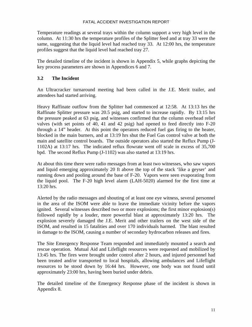
App
endi
x 2
Flow
Dia
gram
of R
affin
ate
Split
ter
Raf
finat
e U
nit O
verv
iew
F
F50
03
AR
U
TT
5506
light
ra
ffina
te
heav
y ra
ffina
te
P50
12
to F
-204
OM
CC
R51
06
T
T550
7
P50
13
T
T55
29T
T55
12
T
T55
13
P500
2
Ref
lux
drum
nor
mal
ly
oper
ates
floo
ded
P
FF
AF
T
1 7037
F
F
F
FT
P
A
T
Reb
oile
r Fur
nace
fuel
ga
s
F50
08
T50
25
F500
5
B-1
101
P500
2A
T55
26
F501
5
Feed
Sur
ge
Dru
mF
-110
1
Raf
finat
e Sp
litte
r
E-1
101
F500
1
AR
U
P
to 3
# V
ent
Gas
Sy
stem
P50
01B
P500
1A
J-11
01/
1101
A
F50
00
L50
07
Split
ter
Botto
ms
C-1
104
A/B
CA
-110
1 J-11
02/1
102
AF5
007
Ref
lux
Dru
m
F-1
102
F51
06
CW
C-1
107
A/B
TK-1
03
Furn
ace
Feed
C-1
104
A/B
CW
C-1
106
A/B
T-5
38
J-11
03/1
103
AT51
14
L510
0L500
8
Nat
ural
Gas
to 3
# V
ent
Gas
Sys
tem
H50
02
App
endi
x 2
Flow
Dia
gram
of R
affin
ate
Split
ter
Raf
finat
e U
nit O
verv
iew
F
F50
03
AR
U
TT
5506
light
ra
ffina
te
heav
y ra
ffina
te
P50
12
to F
-204
OM
CC
R51
06
T
T550
7
P50
13
T
T55
29T
T55
12
T
T55
13
P500
2
Ref
lux
drum
nor
mal
ly
oper
ates
floo
ded

FATAL ACCIDENT INVESTIGATION REPORT
33
P
1
7037
F
L500
8
To 3
# V
ent
Gas
Sys
tem
H50
02
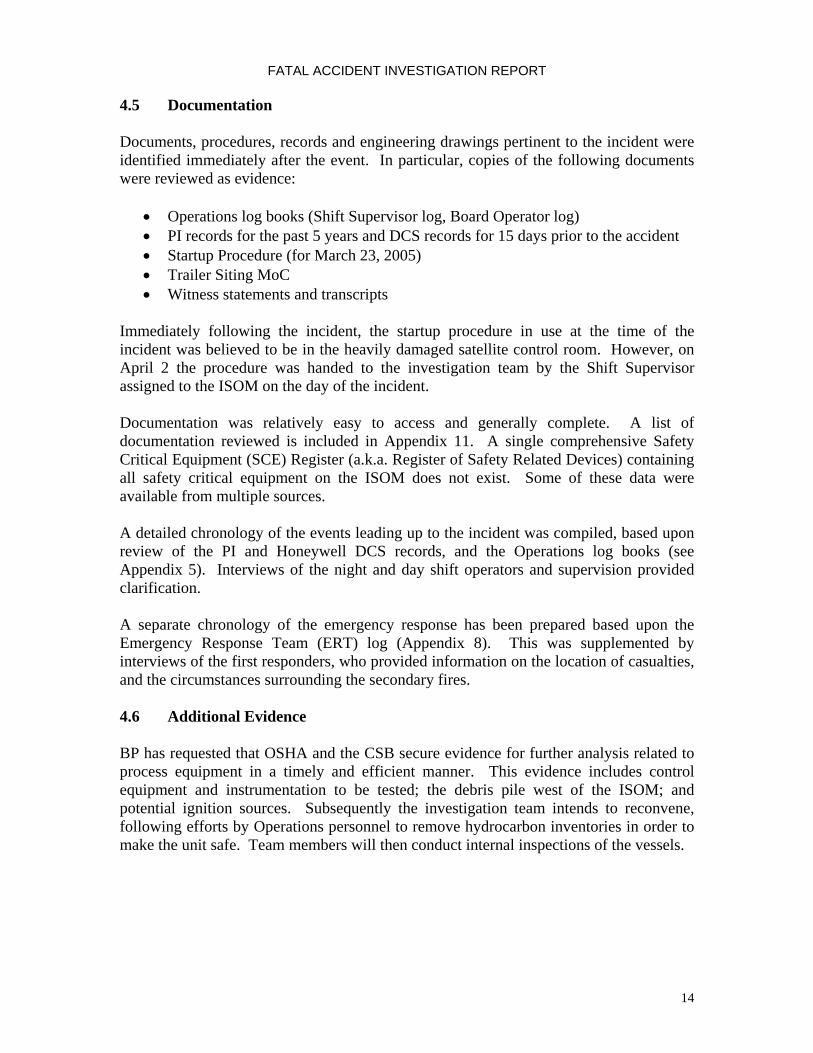
App
endi
x 3
Flow
Dia
gram
of R
affin
ate
Split
ter B
low
dow
n Sy
stem
TT
5506
Raf
finat
e
Split
ter
E-11
01
CA
-110
1
J-11
02/1
102A
F500
7
Ref
lux
Dru
mF-
1102
J-11
03/1
103A
F-20
Blo
w
Dow
n D
rum
From
B-1
101
Feed
RV-
1101
A8”
x10’
42 p
sig
RV-
1101
B4”
x6’
41 p
sig
RV
-110
1C8”
x10’
40 p
sig
RV-
1102
1.5”
x2.5
’70
psi
g
Hea
vy R
affin
ate
Run
dow
n
P50
02R
eflu
x dr
um n
orm
ally
op
erat
es fl
oode
d8”
vent
1.5”
vent
To S
ewer
P
1
7037
F
L500
8
To 3
# V
ent
Gas
Sys
tem
H50
02
App
endi
x 3
Flow
Dia
gram
of R
affin
ate
Split
ter B
low
dow
n Sy
stem
TT
5506
Raf
finat
e
Split
ter
E-11
01
CA
-110
1
J-11
02/1
102A
F500
7
Ref
lux
Dru
mF-
1102
J-11
03/1
103A
F-20
Blo
w
Dow
n D
rum
F-20
Blo
w
Dow
n D
rum
From
B-1
101
Feed
RV-
1101
A8”
x10’
42 p
sig
RV-
1101
B4”
x6’
41 p
sig
RV
-110
1C8”
x10’
40 p
sig
RV-
1102
1.5”
x2.5
’70
psi
g
Hea
vy R
affin
ate
Run
dow
n
P50
02R
eflu
x dr
um n
orm
ally
op
erat
es fl
oode
d8”
vent
1.5”
vent
To S
ewer

FATAL ACCIDENT INVESTIGATION REPORT
34
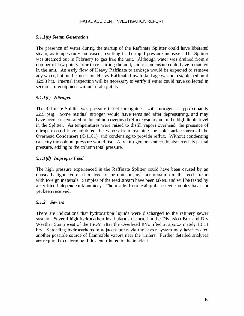
App
endi
x 4:
Plo
t Pla
n of
Isom
eriz
atio
n U
nit
Flar
e Li
ne fr
om N
DU
to A
U2
F-20
E-1
101
B-1101
Aven
ue F
Roa
dway
N
Not
to S
cale
Pipe Rack
F-11
02
F-11
01 ISOM SatelliteControl Room
ISO
M
Aven
ue G
Roa
dway
JE Merit TrailerBP Project Meeting
NDU
Cat
alys
tW
areh
ouse
AU2
Superior
CC
C
Contech I&E James Timec Tool Trailer
Hahn & ClayJames TimecContech I&E
Contech I&E
Appr
ox.
< 15
0 ft
Aro
mat
ics
Rec
over
y U
nit
ULT
RA
CR
AC
KER
Site
of T
urna
roun
d
Tank
Tank
Tank
Tank
5thStreet
App
endi
x 4:
Plo
t Pla
n of
Isom
eriz
atio
n U
nit
Flar
e Li
ne fr
om N
DU
to A
U2
F-20
E-1
101
B-1101
Aven
ue F
Roa
dway
N
Not
to S
cale
Pipe Rack
F-11
02F-
1102
F-11
01F-
1101 ISOM Satellite
Control Room
ISO
M
Aven
ue G
Roa
dway
JE Merit TrailerBP Project Meeting
NDU
Cat
alys
tW
areh
ouse
AU2
Superior
CC
C
Contech I&E James Timec Tool Trailer
Hahn & ClayJames TimecContech I&E
Contech I&E
Appr
ox.
< 15
0 ft
Aro
mat
ics
Rec
over
y U
nit
ULT
RA
CR
AC
KER
Site
of T
urna
roun
d
Tank
Tank
Tank
Tank
5thStreet

FATAL ACCIDENT INVESTIGATION REPORT
35
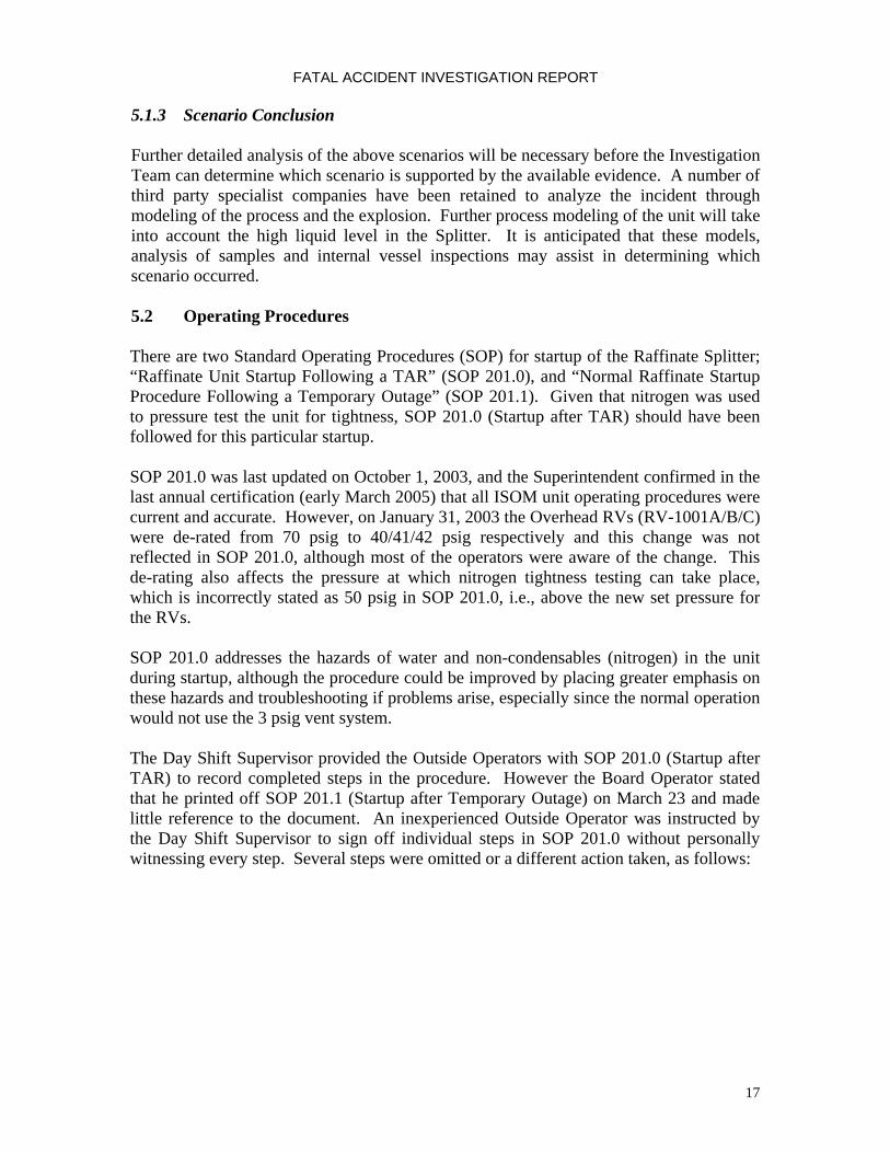
Appendix 5 Chronology Of Events Leading Up To The Incident
Date Time Description Source
2004 1-Sep JE Merit trailer installed west of Isomerization Unit Interview 6-Oct MOC for JE Merit trailer siting approved to proceed MOC form 2005
10-Jan Contech trailer installed west of Isomerization Unit Interview 4-Feb Timec trailer installed west of Isomerization Unit Interview
14-Feb Hahn & Clay trailer installed west of Isomerization Unit
Interview
15-Feb MOC for Contech, Timec and Hahn & Clay trailers siting approved
MOC form
21-Feb Start of temporary outage work schedule. Raffinate Splitter shut down.
26-Feb 17:30 Steam out of Raffinate Splitter PI, Interviews 28-Feb 00:53 Steam out of Raffinate Splitter complete PI 14-Mar Water drained from low points Shift Supervisor Log, Interview21-Mar “Startup Procedure after TAR” printed out Startup Procedure (footer) 21-Mar 14:26 Nitrogen tightness test of Raffinate Splitter to
22.5psig PI, Interviews
21-Mar 18:46 Raffinate Splitter depressured PI 22-Mar ? 6 out of 8 Overhead Condenser fin fans were started Interview 22-Mar 18:00 Shift change 22-Mar 18:00 to 06:00 "Packed E-1101 system with raffinate" Shift Supervisor Log Book 22-Mar 18:00 to 06:00 "Brought in some raff. to unit to pack raff with" Board Operators' Log Book 23-Mar 02:13 Feed charged to Raffinate Splitter at approx. 15,000
bpd PI, Interviews
23-Mar 02:38 Raffinate Splitter base level indication first appears (0%), and gradually increases
PI
23-Mar 02:44 Flow Control Valve to the Reboiler FCV-5005 is opened to charge liquid to the reboiler circuit
PI
23-Mar 02:44 Raffinate Splitter base level falls PI 23-Mar 02:47 Reboiler circulation at 14,000 bpd, and then
increases to 52,000 bpd PI
23-Mar 02:55 Raffinate Splitter base level back to 0%, and then gradually increases
PI
23-Mar 03:08 Feed reduced to approx. 10,000 bpd PI
23-Mar 03:16 Raffinate Splitter base level at full range (100%) PI, Interviews 23-Mar 03:20 Feed to Raffinate Splitter is closed PI 23-Mar 03:20 Reboiler circulation is closed PI 23-Mar 03:20 Raffinate Splitter column pressure stable at 4 psig PI 23-Mar 04:59 Night Shift Supervisor (step-up) leaves site Security Badge Records 23-Mar 06:00 Shift Change 23-Mar 06:00 to 18:00 "Starting Raff unit" Board Operators' Log Book 23-Mar 06:30 Splitter base level at 100%, and starts to fall slightly PI

FATAL ACCIDENT INVESTIGATION REPORT
36
Date Time Description Source
23-Mar ? Day Shift Board Operator prints out copy of “Startup Procedure after Temporary Outage” (Outside Operators had “Startup Procedure after TAR”).
Interview
23-Mar 07:13 Day Shift Supervisor enters site Security Badge Records 23-Mar 08:30 Safety walkthrough at adjacent AU2/NDU units Interviews 23-Mar ? Started preparations for raffinate splitter startup.
Checked line ups. Interview
23-Mar 09:02 Attempted to stroke 3 psig Vent System control valve PI 23-Mar 09:21 Raffinate Splitter column pressure falls from 4 psig to
zero. Chain wheel vent valve around Raffinate Splitter Overhead RV's opened before starting circulation.
PI, Interview
23-Mar ? 3# Vent system not opened as per startup procedure PI, Startup Log 23-Mar 09:28 Raffinate Splitter column pressure at zero, and starts to
increase slowly and steadily PI
23-Mar 09:30 Raffinate Splitter base level at 97% PI 23-Mar 09:38 Heavy Raffinate LCV-5100 valve is stroked. Heavy
Raffinate flow increases to approx. 12,000 bpd for less than 1 minute. LCV-5100 on manual and closed after establishing line up of Heavy Raffinate to tankage.
PI, DCS, Interview
23-Mar ? Light Raffinate lined up to Heavy Raffinate Interview 23-Mar 09:41 Reboiler circulation started at 100,000 bpd PI, Interviews 23-Mar 09:46 Heavy Raffinate LCV-5100 valve is closed. Heavy
Raffinate zero error of 3000 to 4700 bpd. PI
23-Mar 09:52 Feed re-introduced to Raffinate Splitter column at 20,000 bpd
PI, Interviews
23-Mar 09:55 Fuel Gas to Reboiler Heater B-1101 open PI, Interviews 23-Mar 10:00 Increase in Fuel Gas to Reboiler Heater B-1101. First
two burners in Reboiler Heater lit. Raffinate Splitter tray 59 temperature at 80˚F, and starts to increase.
PI, Interviews
23-Mar 10:07 Reboiler Heater outlet temperature at less than 100˚F, and increasing
PI
23-Mar 10:47 Day Shift Supervisor leaves site. Stated he left ARU Shift Supervisor in charge of ISOM
Security Badge Records, Interviews
23-Mar 11:00 Feed preheat to Raffinate Splitter column less than 100˚F (under range)
PI
23-Mar ? Fuel Gas control valve bypass closed. Board Operator has control of Reboiler Heater.
Interview
23-Mar 11:15 Step-Up Supt and ARU Shift Supervisor leaves site Security Badge Records 23-Mar 11:17 Increase in Fuel Gas to Reboiler Heater B-1101. Two
more burners lit in Reboiler Heater. PI, Interviews
23-Mar 11:30 Raffinate Splitter tray 33 temperature and the feed temperature cross
PI
23-Mar 11:30 Fuel Gas to Reboiler Heater B-1101 reasonably stable at 30 - 32,000 scfh
PI
23-Mar ? Outside operators checked Reflux Drum level, and confirmed no level.
Interviews
23-Mar 11:47 Step-Up Operator and Outside Operator leave site Security Badge Records, Interviews
23-Mar 12:00 Raffinate Splitter tray 27 temperature and the feed temperature cross
PI

FATAL ACCIDENT INVESTIGATION REPORT
37
Date Time Description Source
23-Mar 12:03 Step-Up Supt and ARU Shift Supervisor enter site Security Badge Records 23-Mar 12:05 Step-Up Operator and Outside Operator enter site Security Badge Records 23-Mar 12:40 Raffinate Splitter column pressure at 33 psig, and starts
to fall. Chain wheel vent valve around Raffinate Splitter Overhead RV's opened for approx. 10 minutes. Vapors seen emitting from the Blowdown Drum and Stack.
PI, Interviews
23-Mar 12:41 Heavy Raffinate control valve LCV-5100 is opened and put on auto. Appears to be zero error on FT 5015 of 3000 bpd.
PI
23-Mar 12:41 Fuel Gas to Reboiler Heater B-1101 reduced from 32000 scfh to 30000 scfh
PI
23-Mar 12:42 Reboiler Heater outlet temperature stable at 306 - 308˚F PI 23-Mar 12:42 Raffinate Splitter base temperature stable at 302˚F PI 23-Mar 12:45 Safety Meeting in AU-2/ISOM/NDU Control Room for 15
- 20 minutes Interviews
23-Mar 12:48 Raffinate Splitter column tray 33 temperature at 107˚F, and starts to increase rapidly
PI
23-Mar 12:55 Raffinate Splitter column pressure at 22.6 psig PI 23-Mar 12:56 Raffinate Splitter column tray 33 temperature at 156˚F,
and then starts to fall PI
23-Mar 12:57 Raffinate Splitter column tray 59 temperature at 273˚F. PI 23-Mar 12:58 Heavy Raffinate product flow to tankage at zero, and
starts to increase. Assumes zero error of 3000 bpd. PI
23-Mar 13:01 Feed preheat to Raffinate Splitter column at 126˚F, and starts to increase rapidly
PI
23-Mar 13:02 Day Shift Supervisor calls from offsite and speaks to Step-Up Operator, who indicated level problems on F-1101.
Interviews, Telephone records
23-Mar 13:09 Step-Up Operator calls Day Shift Supervisor, who suggested opening 1 ½" Vent around Reflux Drum RV
Interview, Telephone records
23-Mar ? 1 ½” Vent around Reflux Drum RV opened Interviews 23-Mar 13:09 Heavy Raffinate product flow to tankage at 28,000 bpd.
Assumes zero error of 3000 bpd. PI
23-Mar 13:10 Feed preheat to Raffinate Splitter column at 260˚F PI 23-Mar 13:13 Raffinate Splitter column pressure at 20.5 psig, but
starts to increase rapidly PI
23-Mar ? Step-Up Operator called Board Operator on telephone and asked him to cool down B-1101 due to high temperature on Raffinate Splitter bottoms
Interview
23-Mar 13:14 Fuel Gas to Reboiler Heater B-1101 reduced, and outlet temperature starts to fall linearly. Fuel Gas valve output cut from 18% to 15%.
PI, Interview
23-Mar 13:15 Raffinate Splitter column pressure climbs rapidly to 63 psig
PI, Interview
23-Mar 13:15 Raffinate Splitter column tray 27 and 33 temperatures increase rapidly. Raffinate Splitter column tray 13 and overhead temperatures are less than 115˚F, and increase rapidly
PI
23-Mar ? Outside Operators cut 2 burners due to high pressure Interviews 23-Mar 13:16 Reflux Drum low-low level alarm (LALL 5010) clears DCS Alarm Log

FATAL ACCIDENT INVESTIGATION REPORT
38
Date Time Description Source
23-Mar 13:16 Raffinate Splitter base level indication at 78%, but gradually increases to 85%. Suspected false reading.
PI
23-Mar 13:17 Reflux Pump J-1102A started PI, Interviews 23-Mar 13:17 Reflux flow started to Raffinate Splitter column at 35700
bpd (over maximum range). Light Raffinate flowrate at zero, but shows small spike when Reflux Pump started.
PI
23-Mar ? Outside Operators shut off the fires in the furnace and block in the burners
Interviews
23-Mar ? After starting reflux pump, radio reports that Blowdown Drum and Stack (F-20) started overflowing.
Interviews
23-Mar 13:19 Raffinate Splitter column pressure at 54 psig, and starts to fall rapidly
PI
23-Mar 13:19 Reflux Drum low level alarm (LAL 5004) cleared DCS Alarm Log 23-Mar 13:19 Reflux Pump J-1102 started PI 23-Mar 13:19 Fuel Gas to Reboiler Heater (B-1101) closed. Fuel Gas
closed at main board and satellite board. PI, DCS Log, Interviews
23-Mar Approx. 13:20
EXPLOSION
23-Mar 13:20 Blowdown Drum and Stack (F-20) high level alarm (LAH-5020) alarms for 1st time
DCS Alarm Log
23-Mar 13:20 Feed preheat to Raffinate Splitter column at 267˚F, and starts to fall
PI
23-Mar 13:20 Reflux Drum level at zero, and starts to rise PI 23-Mar 13:21 Raffinate Splitter column pressure at 23 psig PI 23-Mar 13:21 Raffinate Splitter column tray 13 and overhead
temperatures at 200˚F and 180˚F respectively PI
23-Mar 13:22 Reflux Drum level at 50%, and then falls slightly PI 23-Mar 13:24 Heavy Raffinate product flow to tankage at 26,700 bpd PI 23-Mar 13:27 Heavy Raffinate product flow to tankage at 21,600 bpd PI 23-Mar 13:29 Night Shift Board Operator enters site Security Badge Records 23-Mar 13:31 Reflux flow to Raffinate Splitter column reduced to
11700 bpd PI
23-Mar 13:32 Reboiler Heater outlet temperature at 257˚F PI 23-Mar 13:33 Reflux flow to Raffinate Splitter column closed PI 23-Mar 13:33 to
13:46 Reflux flow to Raffinate Splitter column occasionally restarted at low flowrate for brief periods
PI
23-Mar 13:44 Heavy Raffinate product flow to tankage at 21,600 bpd, and starts to fall
PI
23-Mar 13:45 Feed to Raffinate Splitter closed PI 23-Mar ? Closed control valves on Raffinate Splitter and ISOM to
help isolate equipment Interview
23-Mar 13:51 Heavy Raffinate product flow to tankage stopped PI 23-Mar 14:30 Feed preheat to Raffinate Splitter column at 160˚F PI 23-Mar 15:10 Raffinate Splitter base level indication falls to 0% PI
Note: There was a time difference between the PI recorded time, and Honeywell DCS
records. The PI data has been used as the basis for this report, and 3 minutes 48 seconds has been added to DCS data to synchronize with PI.

FATAL ACCIDENT INVESTIGATION REPORT
39
01020304050607010:00
10:15
10:30
10:45
11:00
11:15
11:30
11:45
12:00
12:15
12:30
12:45
13:00
13:15
13:30
13:45
14:00
Pressure (psig)
020406080100
120
140
160
Liquid Level in Column (ft)
C
olum
n P
ress
ure
E
stim
ated
Liq
uid
Leve
l
RVs
lift a
t 40
psig
12:5
8 H
eavy
Raf
finat
e ru
ndow
n st
arte
d
8" V
ent O
pene
d;
Vap
ors
from
sta
ck s
een
1 1/
2" V
ent
Ope
ned
09:5
2 20
,000
bpd
feed
intro
duce
d10
:00
1st t
wo
burn
ers
11:1
7 2n
d pa
ir of
bur
ners
lit13
:17
1st R
eflu
x pu
mp
star
ted
13:1
8 Ra
dio
Call -
liqui
d co
min
g fr
om s
tack
13:1
9 2n
d Re
flux
pum
p st
arte
d; a
ll hea
t shu
toff
13:2
0 Ex
plos
ion;
LA
H502
0 A
larm
slit
App
endi
x 6:
Raf
finat
e S
plitt
er C
olum
n Pr
essu
re a
nd L
iqui
d Le
vel
23 M
ar 2
005

FATAL ACCIDENT INVESTIGATION REPORT
40
050100
150
200
250
300
350
10:00
10:15
10:30
10:45
11:00
11:15
11:30
11:45
12:00
12:15
12:30
12:45
13:00
13:15
13:30
13:45
14:00
Temperature (?F)
010203040506070
Pressure (psig)
RVs
lift a
t 40
psig
8" V
ent O
pene
d;
Vap
ors
from
sta
ck s
een
09:5
2 20
,000
bpd
feed
intro
duce
d
10:0
0 1s
t tw
o bu
rner
s lit
11:1
7 2n
d pa
ir of
bur
ners
lit
1 1/
2" V
ent O
pene
d
B
otto
ms
Tem
pera
ture
Tr
ay 2
7 Te
mpe
ratu
re
Feed
Tem
pera
ture
C
olum
n P
ress
ure
App
endi
x 7:
Raf
finat
e S
plitt
er C
olum
n Pr
essu
re &
Tem
pera
ture
s23
Mar
200
5

FATAL ACCIDENT INVESTIGATION REPORT
41
Appendix 8 Emergency Response Chronology
Date Time Description Source
23-Mar 13:45 Fire, search and rescue operation, injuries confirmed, life flight en route, IMT activated ERT Log
23-Mar 14:00 Request 20 firefighters from staging ERT Log 23-Mar 14:05 NDU being secured ERT Log 23-Mar 14:33 All tanks south side OK ERT Log 23-Mar 14:44 Intake Water Clarification Plant keeping up with H2O ERT Log 23-Mar 14:46 Requested 3 more ambulances ERT Log 23-Mar 15:10 Barricade west of unit TAR trailers ERT Log 23-Mar 15:22 Request backhoe north side NDU standby ERT Log 23-Mar 15:25 Pull crews, re-evaluate hot zone ERT Log 23-Mar 15:34 Foam trailer to north side ISOM ERT Log 23-Mar 15:39 25 firefighters from staging to north side of ISOM ERT Log 23-Mar 15:42 Total firefighters on scene 150 - 200 ERT Log 23-Mar 16:08 Texas City Fire Dept Rehab ERT Log 23-Mar 16:09 ISOM/AU2/NDU Operations all accounted ERT Log 23-Mar 16:16 UU3/ARU/ULC Operations all accounted ERT Log 23-Mar 16:18 OMCC all operations & contractor accounted for ERT Log 23-Mar 16:44 Release all ambulances and lifeflight ERT Log 23-Mar 16:55 Texas City Fire Dept released ERT Log 23-Mar 17:44 EAP activated in Medical ERT Log 23-Mar 17:25 Medical examiners in unit area ERT Log 23-Mar 17:54 Choc Bayou Fire Dept released ERT Log 23-Mar 18:25 OMCC operation checking tanks south of ISOM ERT Log 23-Mar 18:28 Areas barricaded off per instruction ERT Log 23-Mar 20:50 Released Texas City Fire Dept Engine 51 and ambulance ERT Log 23-Mar 20:52 Firefighters leaving trailer area, turning over to security ERT Log 23-Mar 21:05 Firefighters (recovery team) at command van area; recovery team
members ERT Log
23-Mar 21:13 SOC has med ex pager if needed tonight to page out ERT Log 23-Mar 21:17 Photographer on unit ERT Log 23-Mar 21:52 Photographer completed photos, scene secured by security ERT Log

FATAL ACCIDENT INVESTIGATION REPORT
42
Appendix 9 Samples
The following process stream samples were taken:
• Raffinate Splitter hydrocarbon liquid feed sample collected from the suction of the Feed Pump (J-1101)
• Raffinate Splitter hydrocarbon liquid bottoms sample collected from the suction of the Heavy Raffinate Pump (J-1103)
• Raffinate Splitter hydrocarbon liquid reflux sample collected from the suction of the Reflux Pump (J-1102)
• Raffinate Splitter overhead product at Light Raffinate Product Coolers (C-1107A/B) outlet
• Blowdown Drum and stack hydrocarbon liquid sample collected from the suction of the Pumpout Pump (J-14A)
• Feed Surge Drum (F-1101) • NESHAP Drum (S-3) oil and water separator • Low point drains on the Raffinate Splitter, Reflux Drum and Reflux Pump for
water • Low point drains on the reflux pipework and Light Raffinate line to storage for
water
FATAL ACCIDENT INVESTIGATION REPORT
43
Appendix 10 Equipment Testing
Vessels It is intended to visually inspect the internals of the Raffinate Splitter column (E-1101), Blowdown Drum & Stack (F-20) and Oily Water Separator. Relief Valves It is intended to remove the following relief valves (RVs) for pop testing and internal inspection:
• Raffinate Splitter overhead line (RV-1001A/B/C), • Reflux Drum (RV-1002), and • Light Raffinate product rundown (RV-1199C)
Control Valves It is intended to remove the following control valves for testing and inspection:
• Light Raffinate Jumpover to Heavy Raffinate (PV-5012) • Raffinate Splitter Reflux Drum to 3 psig Vent System (PV-5002) • Level switches and floats on E-1101, F-20 and Reflux Drum
Instrumentation Key instruments have been identified based upon the pressure, temperature and flowrate parameters of particular interest to the investigation. Once the unit is made safe, these key instruments will be tested to verify if the PI/DCS records are accurate. Of particular interest are the Raffinate Splitter Reflux Drum Level Float Chamber, and E-1101 and F-20 level indicators.

FATAL ACCIDENT INVESTIGATION REPORT
44
Appendix 11 Documentation
The following relevant documentation was collected for review:
• Organization Chart/Manning • Process Safety Information, including Process & Instrument Diagrams and
Engineering Drawings • Process Hazard Analysis and Risk Assessments (Hazops and MARS etc.) • Operating Procedures • Safe Work Practices • Authorization To Work (ATW) Permits issued at the time of the accident • Equipment Isolation Procedures and Certificates (LOTO) • Training Guides and records • Mechanical Integrity, including equipment inspection records • Management of Change records • Incident Investigations, including records of past incidents • Emergency Response logs • Technical Reports • Process Safety Booklets • Plot plans • Aerial photographs • Video clips • Refinery budgets and plans • Facility siting plans

FATAL ACCIDENT INVESTIGATION REPORT
45
MAI
NTE
NA
NC
ESU
PER
VISO
RS
(4)
SUPE
RIN
TEN
DEN
TU
ltraf
orm
er U
nit 4
/D
istil
late
Des
ulfu
rizin
g U
nit
MAI
NTE
NA
NC
EEN
GIN
EER
S(6
)
SUPE
RIN
TEN
DEN
TM
AIN
TEN
AN
CE
ULT
RAC
RAC
KER
TU
RN
ARO
UN
D
SIN
GLE
PO
INT
OF
ACC
OU
NTA
BILI
TY
OPT
IMIZ
ATIO
N
ENG
INEE
RS
(6)
SUPE
RIN
TEN
DEN
TPR
OC
ESS
&
TEC
HN
OLO
GY
OPE
RAT
ION
S SU
PER
VISO
RS
Ultr
afor
mer
Uni
t 4/
Dis
tilla
te D
esul
furiz
ing
Uni
t(4
)
OPE
RAT
ION
SC
OO
RD
INAT
OR
Ultr
afor
mer
Uni
t 4/
Dis
tilla
te D
esul
furiz
ing
Uni
t
MAN
UFA
CTU
RIN
G D
ELIV
ER
Y LE
AD
ER
PRO
CES
S C
ON
TRO
L EN
GIN
EER
S(3
)
ENG
INEE
RIN
G
SUPE
RVI
SOR
ADM
INIS
TRAT
IVE
ASSI
STAN
T
SUPE
RIN
TEN
DEN
TU
ltrac
rack
er
OPE
RAT
ION
S SU
PER
VISO
RS
Ultr
acra
cker
(4)
OPE
RAT
ION
SC
OO
RD
INAT
OR
Ultr
acra
cker
SUPE
RIN
TEN
DEN
TU
ltraf
orm
er U
nit 3
OPE
RAT
ION
S
CO
OR
DIN
ATO
R
U
ltraf
orm
er U
nit 3
OPE
RAT
ION
S SU
PER
VISO
RS
Ultr
afor
mer
Uni
t 3(4
)
TRAI
NIN
G
CO
OR
DIN
ATO
RU
ltraf
orm
er U
nit 3
(ope
n)
PRO
CES
S C
ON
TRO
L SP
ECIA
LIST
(3)
SUPE
RIN
TEN
DEN
TAr
omat
ics
Uni
t 2Is
omer
izat
ion
Nap
tha
Des
ulfu
rizat
ion
Uni
tAr
omat
ics
Rec
over
y U
nit
OPE
RAT
ION
S SU
PER
VISO
RS
Arom
atic
s U
nit 2
Isom
eriz
atio
nN
apth
a D
esul
furiz
atio
n U
nit
Arom
atic
s R
ecov
ery
Uni
t (4
)
OPE
RAT
ION
SC
OO
RD
INAT
OR
Arom
atic
s U
nit 2
Isom
eriz
atio
nN
apth
a D
esul
furiz
atio
n U
nit
Arom
atic
s R
ecov
ery
Uni
t
TRAI
NIN
G C
OO
RD
INAT
OR
Arom
atic
s U
nit 2
Isom
eriz
atio
nN
apth
a D
esul
furiz
atio
n U
nit
Arom
atic
s R
ecov
ery
Uni
t
TUR
NAR
OU
ND
C
OO
RD
INAT
OR
MEC
HA
NIC
AL
INTE
GR
ITY
MAN
AGER
PER
FOR
MA
NC
E
TEAM
LEA
DER
TUR
NAR
OU
ND
SU
PER
VISO
R(o
pen)
OE
TEA
M L
EAD
ER
CO
MPL
IAN
CE
DEL
IVE
RY/
M
AIN
TEN
AN
CE
TRAI
NIN
G(T
O B
E N
AME
D)
INST
RU
ME
NT
& EL
ECTR
ICAL
EN
GIN
EER
S(2
)(O
NE
POSI
TIO
N IS
TO
BE
NA
MED
)
CO
MPL
IAN
CE
DEL
IVE
RY
/REL
IABI
LITY
C
ENTE
RED
M
AIN
TEN
AN
CE
(TO
BE
NAM
ED
)TR
AIN
ING
CO
OR
DIN
ATO
RU
ltraf
orm
er U
nit 4
/D
istil
late
Des
ulfu
rizin
g U
nit
PER
FOR
MA
NC
E
ANAL
YST
(TO
BE
NAM
ED
)
PER
FOR
MA
NC
E AN
ALYS
T
TUR
NAR
OU
ND
SU
PER
INTE
ND
ENT
MO
TOR
IZAT
ION
PR
OJE
CT
MAN
AGE
RTU
RN
ARO
UN
D
SUPE
RVI
SOR
TRA
ININ
G
CO
OR
DIN
ATO
R
Hea
lth, S
afet
y &
Envi
ronm
enta
l/Pro
cess
Saf
ety
Man
agem
ent
(Hou
rly P
ositi
on o
pen
)
HEA
LTH,
SAF
EY,
SEC
UR
ITY
, AN
D
ENVI
RO
NM
EN
TAL
CO
OR
DIN
ATO
R
PRO
CES
S SA
FETY
M
ANAG
EMEN
T(4
Hou
rly o
pen
)
SYST
EMS
SHIF
T SU
PER
VISO
RS
(4)
CO
ST A
NAL
YST
(Con
tract
or)
INSP
ECTO
RS
Ultr
afor
mer
Uni
t 3(1
)U
ltraf
orm
er U
nit 4
/D
istil
late
D
esul
furiz
ing
Uni
t(1
)Ar
omat
ics
Uni
t 2Is
omer
izat
ion
Nap
tha
Des
ulfu
rizat
ion
Uni
tAr
omat
ics
Rec
over
y U
nit
(1)
Ultr
acra
cker
(1)
WES
T P
LAN
T
PRO
CES
S TE
CH
NO
LOG
Y EN
GIN
EER
S(2
)
Ultr
acra
cker
Ope
rato
rs
A, B
, & C
Shi
ftO
utsi
de O
pera
tor –
3Bo
ard
Ope
rato
r –2
Proc
ess
Tech
nici
an –
1
D S
hift
Out
side
Ope
rato
r -4
Boar
d O
pera
tor -
2Pr
oces
s Te
chni
cian
–1
U S
hift
Turn
arou
nd
Coo
rdin
ator
–1
Mai
nten
ance
C
oord
inat
or -
1
Arom
atic
s R
ecov
ery
Uni
t O
pera
tors
A Sh
iftO
utsi
de O
pera
tor –
1Bo
ard
Ope
rato
r –1
Proc
ess
Tech
nici
an –
1B
Shift
Out
side
Ope
rato
r -2
Boar
d O
pera
tor -
1Pr
oces
s Te
chni
cian
–1
C &
D S
hift
Out
side
Ope
rato
r –2
Boar
d O
pera
tor –
1Pr
oces
s Te
chni
cian
–1
Arom
atic
s U
nit 2
Isom
eriz
atio
nN
apth
a D
esul
furiz
atio
n U
nit
Ope
rato
rsA
Shift
Out
side
Ope
rato
r –3
Boar
d O
pera
tor –
1Pr
oces
s Te
chni
cian
–1
B &
D S
hift
Out
side
Ope
rato
r -4
Boar
d O
pera
tor -
1Pr
oces
s Te
chni
cian
–1
C S
hift
Out
side
Ope
rato
r –2
Boar
d O
pera
tor –
1Pr
oces
s Te
chni
cian
–1
Ultr
afor
mer
Uni
t 3
Ope
rato
rs
A Sh
iftO
utsi
de O
pera
tor –
2Bo
ard
Ope
rato
r –1
Proc
ess
Tech
nici
an –
1
B Sh
iftO
utsi
de O
pera
tor -
3Bo
ard
Ope
rato
r -1
Proc
ess
Tech
nici
an –
1
C S
hift
Out
side
Ope
rato
r -1
Boar
d O
pera
tor -
1Pr
oces
s Te
chni
cian
–1
D S
hift
Out
side
Ope
rato
r -2
Boar
d O
pera
tor -
1
U S
hift
Proc
ess
Tech
nici
an -1
Mai
nten
ance
C
oord
inat
or -
1
Ultr
afor
mer
Uni
t 4 /
Dis
tilla
te D
esul
furiz
ing
Uni
t Ope
rato
rs
A Sh
iftO
utsi
de O
pera
tor –
3Bo
ard
Ope
rato
r –2
Proc
ess
Tech
nici
an –
1
B Sh
iftO
utsi
de O
pera
tor -
4Bo
ard
Ope
rato
r -2
C S
hift
Out
side
Ope
rato
r -4
Boar
d O
pera
tor -
1Pr
oces
s Te
chni
cian
–1
D S
hift
Out
side
Ope
rato
r -2
Boar
d O
pera
tor –
2Pr
oces
s Te
chni
cian
-1
U S
hift
Mai
nten
ance
C
oord
inat
or -
2
Mai
nten
ance
Cra
fts
Arom
atic
s U
nit 2
Isom
eriz
atio
nN
apth
a D
esul
furiz
atio
n U
nit
Arom
atic
s R
ecov
ery
Uni
t M
achi
nist
s –
3In
stru
men
t/Ele
ctric
al –
3Pi
pew
elde
r –4
Ultr
acra
cker
Mac
hini
st –
4In
stru
men
t/Ele
ctric
al –
3Pi
pew
elde
r –2
Pipe
fitte
r –4
Ultr
afor
mer
Uni
t 3M
achi
nist
–2
Inst
rum
ent/E
lect
rical
–2
Pipe
fitte
r –5
Ultr
afor
mer
Uni
t 4 /
Dis
tilla
te D
esul
furiz
ing
Uni
tM
achi
nist
–2
Inst
rum
ent/E
lect
rical
–3
Pipe
wel
der –
3Pi
pefit
ter -
1
Appe
ndix
12
Wes
t Pla
nt O
rgan
izat
iona
l Cha
rt
MAI
NTE
NA
NC
ESU
PER
VISO
RS
(4)
SUPE
RIN
TEN
DEN
TU
ltraf
orm
er U
nit 4
/D
istil
late
Des
ulfu
rizin
g U
nit
MAI
NTE
NA
NC
EEN
GIN
EER
S(6
)
SUPE
RIN
TEN
DEN
TM
AIN
TEN
AN
CE
ULT
RAC
RAC
KER
TU
RN
ARO
UN
D
SIN
GLE
PO
INT
OF
ACC
OU
NTA
BILI
TY
OPT
IMIZ
ATIO
N
ENG
INEE
RS
(6)
SUPE
RIN
TEN
DEN
TPR
OC
ESS
&
TEC
HN
OLO
GY
OPE
RAT
ION
S SU
PER
VISO
RS
Ultr
afor
mer
Uni
t 4/
Dis
tilla
te D
esul
furiz
ing
Uni
t(4
)
OPE
RAT
ION
SC
OO
RD
INAT
OR
Ultr
afor
mer
Uni
t 4/
Dis
tilla
te D
esul
furiz
ing
Uni
t
MAN
UFA
CTU
RIN
G D
ELIV
ER
Y LE
AD
ER
PRO
CES
S C
ON
TRO
L EN
GIN
EER
S(3
)
ENG
INEE
RIN
G
SUPE
RVI
SOR
ADM
INIS
TRAT
IVE
ASSI
STAN
T
SUPE
RIN
TEN
DEN
TU
ltrac
rack
er
OPE
RAT
ION
S SU
PER
VISO
RS
Ultr
acra
cker
(4)
OPE
RAT
ION
SC
OO
RD
INAT
OR
Ultr
acra
cker
SUPE
RIN
TEN
DEN
TU
ltraf
orm
er U
nit 3
OPE
RAT
ION
S
CO
OR
DIN
ATO
R
U
ltraf
orm
er U
nit 3
OPE
RAT
ION
S SU
PER
VISO
RS
Ultr
afor
mer
Uni
t 3(4
)
TRAI
NIN
G
CO
OR
DIN
ATO
RU
ltraf
orm
er U
nit 3
(ope
n)
PRO
CES
S C
ON
TRO
L SP
ECIA
LIST
(3)
SUPE
RIN
TEN
DEN
TAr
omat
ics
Uni
t 2Is
omer
izat
ion
Nap
tha
Des
ulfu
rizat
ion
Uni
tAr
omat
ics
Rec
over
y U
nit
OPE
RAT
ION
S SU
PER
VISO
RS
Arom
atic
s U
nit 2
Isom
eriz
atio
nN
apth
a D
esul
furiz
atio
n U
nit
Arom
atic
s R
ecov
ery
Uni
t (4
)
OPE
RAT
ION
SC
OO
RD
INAT
OR
Arom
atic
s U
nit 2
Isom
eriz
atio
nN
apth
a D
esul
furiz
atio
n U
nit
Arom
atic
s R
ecov
ery
Uni
t
TRAI
NIN
G C
OO
RD
INAT
OR
Arom
atic
s U
nit 2
Isom
eriz
atio
nN
apth
a D
esul
furiz
atio
n U
nit
Arom
atic
s R
ecov
ery
Uni
t
TUR
NAR
OU
ND
C
OO
RD
INAT
OR
MEC
HA
NIC
AL
INTE
GR
ITY
MAN
AGER
PER
FOR
MA
NC
E
TEAM
LEA
DER
TUR
NAR
OU
ND
SU
PER
VISO
R(o
pen)
OE
TEA
M L
EAD
ER
CO
MPL
IAN
CE
DEL
IVE
RY/
M
AIN
TEN
AN
CE
TRAI
NIN
G(T
O B
E N
AME
D)
INST
RU
ME
NT
& EL
ECTR
ICAL
EN
GIN
EER
S(2
)(O
NE
POSI
TIO
N IS
TO
BE
NA
MED
)
CO
MPL
IAN
CE
DEL
IVE
RY
/REL
IABI
LITY
C
ENTE
RED
M
AIN
TEN
AN
CE
(TO
BE
NAM
ED
)TR
AIN
ING
CO
OR
DIN
ATO
RU
ltraf
orm
er U
nit 4
/D
istil
late
Des
ulfu
rizin
g U
nit
PER
FOR
MA
NC
E
ANAL
YST
(TO
BE
NAM
ED
)
PER
FOR
MA
NC
E AN
ALYS
T
TUR
NAR
OU
ND
SU
PER
INTE
ND
ENT
MO
TOR
IZAT
ION
PR
OJE
CT
MAN
AGE
RTU
RN
ARO
UN
D
SUPE
RVI
SOR
TRA
ININ
G
CO
OR
DIN
ATO
R
Hea
lth, S
afet
y &
Envi
ronm
enta
l/Pro
cess
Saf
ety
Man
agem
ent
(Hou
rly P
ositi
on o
pen
)
HEA
LTH,
SAF
EY,
SEC
UR
ITY
, AN
D
ENVI
RO
NM
EN
TAL
CO
OR
DIN
ATO
R
PRO
CES
S SA
FETY
M
ANAG
EMEN
T(4
Hou
rly o
pen
)
SYST
EMS
SHIF
T SU
PER
VISO
RS
(4)
CO
ST A
NAL
YST
(Con
tract
or)
INSP
ECTO
RS
Ultr
afor
mer
Uni
t 3(1
)U
ltraf
orm
er U
nit 4
/D
istil
late
D
esul
furiz
ing
Uni
t(1
)Ar
omat
ics
Uni
t 2Is
omer
izat
ion
Nap
tha
Des
ulfu
rizat
ion
Uni
tAr
omat
ics
Rec
over
y U
nit
(1)
Ultr
acra
cker
(1)
WES
T P
LAN
T
PRO
CES
S TE
CH
NO
LOG
Y EN
GIN
EER
S(2
)
Ultr
acra
cker
Ope
rato
rs
A, B
, & C
Shi
ftO
utsi
de O
pera
tor –
3Bo
ard
Ope
rato
r –2
Proc
ess
Tech
nici
an –
1
D S
hift
Out
side
Ope
rato
r -4
Boar
d O
pera
tor -
2Pr
oces
s Te
chni
cian
–1
U S
hift
Turn
arou
nd
Coo
rdin
ator
–1
Mai
nten
ance
C
oord
inat
or -
1
Arom
atic
s R
ecov
ery
Uni
t O
pera
tors
A Sh
iftO
utsi
de O
pera
tor –
1Bo
ard
Ope
rato
r –1
Proc
ess
Tech
nici
an –
1B
Shift
Out
side
Ope
rato
r -2
Boar
d O
pera
tor -
1Pr
oces
s Te
chni
cian
–1
C &
D S
hift
Out
side
Ope
rato
r –2
Boar
d O
pera
tor –
1Pr
oces
s Te
chni
cian
–1
Arom
atic
s U
nit 2
Isom
eriz
atio
nN
apth
a D
esul
furiz
atio
n U
nit
Ope
rato
rsA
Shift
Out
side
Ope
rato
r –3
Boar
d O
pera
tor –
1Pr
oces
s Te
chni
cian
–1
B &
D S
hift
Out
side
Ope
rato
r -4
Boar
d O
pera
tor -
1Pr
oces
s Te
chni
cian
–1
C S
hift
Out
side
Ope
rato
r –2
Boar
d O
pera
tor –
1Pr
oces
s Te
chni
cian
–1
Ultr
afor
mer
Uni
t 3
Ope
rato
rs
A Sh
iftO
utsi
de O
pera
tor –
2Bo
ard
Ope
rato
r –1
Proc
ess
Tech
nici
an –
1
B Sh
iftO
utsi
de O
pera
tor -
3Bo
ard
Ope
rato
r -1
Proc
ess
Tech
nici
an –
1
C S
hift
Out
side
Ope
rato
r -1
Boar
d O
pera
tor -
1Pr
oces
s Te
chni
cian
–1
D S
hift
Out
side
Ope
rato
r -2
Boar
d O
pera
tor -
1
U S
hift
Proc
ess
Tech
nici
an -1
Mai
nten
ance
C
oord
inat
or -
1
Ultr
afor
mer
Uni
t 4 /
Dis
tilla
te D
esul
furiz
ing
Uni
t Ope
rato
rs
A Sh
iftO
utsi
de O
pera
tor –
3Bo
ard
Ope
rato
r –2
Proc
ess
Tech
nici
an –
1
B Sh
iftO
utsi
de O
pera
tor -
4Bo
ard
Ope
rato
r -2
C S
hift
Out
side
Ope
rato
r -4
Boar
d O
pera
tor -
1Pr
oces
s Te
chni
cian
–1
D S
hift
Out
side
Ope
rato
r -2
Boar
d O
pera
tor –
2Pr
oces
s Te
chni
cian
-1
U S
hift
Mai
nten
ance
C
oord
inat
or -
2
Mai
nten
ance
Cra
fts
Arom
atic
s U
nit 2
Isom
eriz
atio
nN
apth
a D
esul
furiz
atio
n U
nit
Arom
atic
s R
ecov
ery
Uni
t M
achi
nist
s –
3In
stru
men
t/Ele
ctric
al –
3Pi
pew
elde
r –4
Ultr
acra
cker
Mac
hini
st –
4In
stru
men
t/Ele
ctric
al –
3Pi
pew
elde
r –2
Pipe
fitte
r –4
Ultr
afor
mer
Uni
t 3M
achi
nist
–2
Inst
rum
ent/E
lect
rical
–2
Pipe
fitte
r –5
Ultr
afor
mer
Uni
t 4 /
Dis
tilla
te D
esul
furiz
ing
Uni
tM
achi
nist
–2
Inst
rum
ent/E
lect
rical
–3
Pipe
wel
der –
3Pi
pefit
ter -
1
MAI
NTE
NA
NC
ESU
PER
VISO
RS
(4)
SUPE
RIN
TEN
DEN
TU
ltraf
orm
er U
nit 4
/D
istil
late
Des
ulfu
rizin
g U
nit
MAI
NTE
NA
NC
EEN
GIN
EER
S(6
)
SUPE
RIN
TEN
DEN
TM
AIN
TEN
AN
CE
ULT
RAC
RAC
KER
TU
RN
ARO
UN
D
SIN
GLE
PO
INT
OF
ACC
OU
NTA
BILI
TY
OPT
IMIZ
ATIO
N
ENG
INEE
RS
(6)
SUPE
RIN
TEN
DEN
TPR
OC
ESS
&
TEC
HN
OLO
GY
OPE
RAT
ION
S SU
PER
VISO
RS
Ultr
afor
mer
Uni
t 4/
Dis
tilla
te D
esul
furiz
ing
Uni
t(4
)
OPE
RAT
ION
SC
OO
RD
INAT
OR
Ultr
afor
mer
Uni
t 4/
Dis
tilla
te D
esul
furiz
ing
Uni
t
MAN
UFA
CTU
RIN
G D
ELIV
ER
Y LE
AD
ER
PRO
CES
S C
ON
TRO
L EN
GIN
EER
S(3
)
ENG
INEE
RIN
G
SUPE
RVI
SOR
ADM
INIS
TRAT
IVE
ASSI
STAN
T
SUPE
RIN
TEN
DEN
TU
ltrac
rack
er
OPE
RAT
ION
S SU
PER
VISO
RS
Ultr
acra
cker
(4)
OPE
RAT
ION
SC
OO
RD
INAT
OR
Ultr
acra
cker
SUPE
RIN
TEN
DEN
TU
ltraf
orm
er U
nit 3
OPE
RAT
ION
S
CO
OR
DIN
ATO
R
U
ltraf
orm
er U
nit 3
OPE
RAT
ION
S SU
PER
VISO
RS
Ultr
afor
mer
Uni
t 3(4
)
TRAI
NIN
G
CO
OR
DIN
ATO
RU
ltraf
orm
er U
nit 3
(ope
n)
PRO
CES
S C
ON
TRO
L SP
ECIA
LIST
(3)
SUPE
RIN
TEN
DEN
TAr
omat
ics
Uni
t 2Is
omer
izat
ion
Nap
tha
Des
ulfu
rizat
ion
Uni
tAr
omat
ics
Rec
over
y U
nit
OPE
RAT
ION
S SU
PER
VISO
RS
Arom
atic
s U
nit 2
Isom
eriz
atio
nN
apth
a D
esul
furiz
atio
n U
nit
Arom
atic
s R
ecov
ery
Uni
t (4
)
OPE
RAT
ION
SC
OO
RD
INAT
OR
Arom
atic
s U
nit 2
Isom
eriz
atio
nN
apth
a D
esul
furiz
atio
n U
nit
Arom
atic
s R
ecov
ery
Uni
t
TRAI
NIN
G C
OO
RD
INAT
OR
Arom
atic
s U
nit 2
Isom
eriz
atio
nN
apth
a D
esul
furiz
atio
n U
nit
Arom
atic
s R
ecov
ery
Uni
t
TUR
NAR
OU
ND
C
OO
RD
INAT
OR
MEC
HA
NIC
AL
INTE
GR
ITY
MAN
AGER
PER
FOR
MA
NC
E
TEAM
LEA
DER
TUR
NAR
OU
ND
MAI
NTE
NA
NC
ESU
PER
VISO
RS
(4)
SUPE
RIN
TEN
DEN
TU
ltraf
orm
er U
nit 4
/D
istil
late
Des
ulfu
rizin
g U
nit
MAI
NTE
NA
NC
EEN
GIN
EER
S(6
)
SUPE
RIN
TEN
DEN
TM
AIN
TEN
AN
CE
ULT
RAC
RAC
KER
TU
RN
ARO
UN
D
SIN
GLE
PO
INT
OF
ACC
OU
NTA
BILI
TY
OPT
IMIZ
ATIO
N
ENG
INEE
RS
(6)
SUPE
RIN
TEN
DEN
TPR
OC
ESS
&
TEC
HN
OLO
GY
OPE
RAT
ION
S SU
PER
VISO
RS
Ultr
afor
mer
Uni
t 4/
Dis
tilla
te D
esul
furiz
ing
Uni
t(4
)
OPE
RAT
ION
SC
OO
RD
INAT
OR
Ultr
afor
mer
Uni
t 4/
Dis
tilla
te D
esul
furiz
ing
Uni
t
MAN
UFA
CTU
RIN
G D
ELIV
ER
Y LE
AD
ER
PRO
CES
S C
ON
TRO
L EN
GIN
EER
S(3
)
ENG
INEE
RIN
G
SUPE
RVI
SOR
ADM
INIS
TRAT
IVE
ASSI
STAN
T
SUPE
RIN
TEN
DEN
TU
ltrac
rack
er
OPE
RAT
ION
S SU
PER
VISO
RS
Ultr
acra
cker
(4)
OPE
RAT
ION
SC
OO
RD
INAT
OR
Ultr
acra
cker
SUPE
RIN
TEN
DEN
TU
ltraf
orm
er U
nit 3
OPE
RAT
ION
S
CO
OR
DIN
ATO
R
U
ltraf
orm
er U
nit 3
OPE
RAT
ION
S SU
PER
VISO
RS
Ultr
afor
mer
Uni
t 3(4
)
TRAI
NIN
G
CO
OR
DIN
ATO
RU
ltraf
orm
er U
nit 3
(ope
n)
PRO
CES
S C
ON
TRO
L SP
ECIA
LIST
(3)
SUPE
RIN
TEN
DEN
TAr
omat
ics
Uni
t 2Is
omer
izat
ion
Nap
tha
Des
ulfu
rizat
ion
Uni
tAr
omat
ics
Rec
over
y U
nit
OPE
RAT
ION
S SU
PER
VISO
RS
Arom
atic
s U
nit 2
Isom
eriz
atio
nN
apth
a D
esul
furiz
atio
n U
nit
Arom
atic
s R
ecov
ery
Uni
t (4
)
OPE
RAT
ION
SC
OO
RD
INAT
OR
Arom
atic
s U
nit 2
Isom
eriz
atio
nN
apth
a D
esul
furiz
atio
n U
nit
Arom
atic
s R
ecov
ery
Uni
t
TRAI
NIN
G C
OO
RD
INAT
OR
Arom
atic
s U
nit 2
Isom
eriz
atio
nN
apth
a D
esul
furiz
atio
n U
nit
Arom
atic
s R
ecov
ery
Uni
t
TUR
NAR
OU
ND
C
OO
RD
INAT
OR
MEC
HA
NIC
AL
INTE
GR
ITY
MAN
AGER
PER
FOR
MA
NC
E
TEAM
LEA
DER
TUR
NAR
OU
ND
SU
PER
VISO
R(o
pen)
OE
TEA
M L
EAD
ER
CO
MPL
IAN
CE
DEL
IVE
RY/
M
AIN
TEN
AN
CE
TRAI
NIN
G(T
O B
E N
AME
D)
INST
RU
ME
NT
& EL
ECTR
ICAL
EN
GIN
EER
S(2
)(O
NE
POSI
TIO
N IS
TO
BE
NA
MED
)
CO
MPL
IAN
CE
DEL
IVE
RY
/REL
IABI
LITY
C
ENTE
RED
M
AIN
TEN
AN
CE
(TO
BE
NAM
ED
)TR
AIN
ING
CO
OR
DIN
ATO
RU
ltraf
orm
er U
nit 4
/D
istil
late
Des
ulfu
rizin
g U
nit
PER
FOR
MA
NC
E
ANAL
YST
(TO
BE
NAM
ED
)
PER
FOR
MA
NC
E AN
ALYS
T
TUR
NAR
OU
ND
SU
PER
INTE
ND
ENT
MO
TOR
IZAT
ION
PR
OJE
CT
MAN
AGE
RTU
RN
ARO
UN
D
SUPE
RVI
SOR
TRA
ININ
G
CO
OR
DIN
ATO
R
Hea
lth, S
afet
y &
Envi
ronm
enta
l/Pro
cess
Saf
ety
Man
agem
ent
(Hou
rly P
ositi
on o
pen
)
HEA
LTH,
SAF
EY,
SEC
UR
ITY
, AN
D
ENVI
RO
NM
EN
TAL
CO
OR
DIN
ATO
R
PRO
CES
S SA
FETY
M
ANAG
EMEN
T(4
Hou
rly o
pen
)
SYST
EMS
SHIF
T SU
PER
VISO
RS
(4)
CO
ST A
NAL
YST
(Con
tract
or)
INSP
ECTO
RS
Ultr
afor
mer
Uni
t 3(1
)U
ltraf
orm
er U
nit 4
/D
istil
late
D
esul
furiz
ing
Uni
t(1
)Ar
omat
ics
Uni
t 2Is
omer
izat
ion
Nap
tha
Des
ulfu
rizat
ion
Uni
tAr
omat
ics
Rec
over
y U
nit
(1)
Ultr
acra
cker
(1)
WES
T P
LAN
T
PRO
CES
S TE
CH
NO
LOG
Y EN
GIN
EER
S(2
)
Ultr
acra
cker
Ope
rato
rs
A, B
, & C
Shi
ftO
utsi
de O
pera
tor –
3Bo
ard
Ope
rato
r –2
Proc
ess
Tech
nici
an –
1
D S
hift
Out
side
Ope
rato
r -
SUPE
RVI
SOR
(ope
n)
OE
TEA
M L
EAD
ER
CO
MPL
IAN
CE
DEL
IVE
RY/
M
AIN
TEN
AN
CE
TRAI
NIN
G(T
O B
E N
AME
D)
INST
RU
ME
NT
& EL
ECTR
ICAL
EN
GIN
EER
S(2
)(O
NE
POSI
TIO
N IS
TO
BE
NA
MED
)
CO
MPL
IAN
CE
DEL
IVE
RY
/REL
IABI
LITY
C
ENTE
RED
M
AIN
TEN
AN
CE
(TO
BE
NAM
ED
)TR
AIN
ING
CO
OR
DIN
ATO
RU
ltraf
orm
er U
nit 4
/D
istil
late
Des
ulfu
rizin
g U
nit
PER
FOR
MA
NC
E
ANAL
YST
(TO
BE
NAM
ED
)
PER
FOR
MA
NC
E AN
ALYS
T
TUR
NAR
OU
ND
SU
PER
INTE
ND
ENT
MO
TOR
IZAT
ION
PR
OJE
CT
MAN
AGE
RTU
RN
ARO
UN
D
SUPE
RVI
SOR
TRA
ININ
G
CO
OR
DIN
ATO
R
Hea
lth, S
afet
y &
Envi
ronm
enta
l/Pro
cess
Saf
ety
Man
agem
ent
(Hou
rly P
ositi
on o
pen
)
HEA
LTH,
SAF
EY,
SEC
UR
ITY
, AN
D
ENVI
RO
NM
EN
TAL
CO
OR
DIN
ATO
R
PRO
CES
S SA
FETY
M
ANAG
EMEN
T(4
Hou
rly o
pen
)
SYST
EMS
SHIF
T SU
PER
VISO
RS
(4)
CO
ST A
NAL
YST
(Con
tract
or)
INSP
ECTO
RS
Ultr
afor
mer
Uni
t 3(1
)U
ltraf
orm
er U
nit 4
/D
istil
late
D
esul
furiz
ing
Uni
t(1
)Ar
omat
ics
Uni
t 2Is
omer
izat
ion
Nap
tha
Des
ulfu
rizat
ion
Uni
tAr
omat
ics
Rec
over
y U
nit
(1)
Ultr
acra
cker
(1)
WES
T P
LAN
T
PRO
CES
S TE
CH
NO
LOG
Y EN
GIN
EER
S(2
)
Ultr
acra
cker
Ope
rato
rs
A, B
, & C
Shi
ftO
utsi
de O
pera
tor –
3Bo
ard
Ope
rato
r –2
Proc
ess
Tech
nici
an –
1
D S
hift
Out
side
Ope
rato
r -4
Boar
d O
pera
tor -
2Pr
oces
s Te
chni
cian
–1
U S
hift
Turn
arou
nd
Coo
rdin
ator
–1
Mai
nten
ance
C
oord
inat
or -
1
Arom
atic
s R
ecov
ery
Uni
t O
pera
tors
A Sh
iftO
utsi
de O
pera
tor –
1Bo
ard
Ope
rato
r –1
Proc
ess
Tech
nici
an –
1B
Shift
Out
side
Ope
rato
r -2
Boar
d O
pera
tor -
1Pr
oces
s Te
chni
cian
–1
C &
D S
hift
Out
side
Ope
rato
r –2
Boar
d O
pera
tor –
1Pr
oces
s Te
chni
cian
–1
Arom
atic
s U
nit 2
Isom
eriz
atio
nN
apth
a D
esul
furiz
atio
n U
nit
Ope
rato
rsA
Shift
Out
side
Ope
rato
r –3
Boar
d O
pera
tor –
1Pr
oces
s Te
chni
cian
–1
B &
D S
hift
Out
side
Ope
rato
r -4
Boar
d O
pera
tor -
1Pr
oces
s Te
chni
cian
–1
C S
hift
Out
side
Ope
rato
r –2
Boar
d O
pera
tor –
1Pr
oces
s Te
chni
cian
–1
Ultr
afor
mer
Uni
t 3
Ope
rato
rs
A Sh
iftO
utsi
de O
pera
tor –
2Bo
ard
Ope
rato
r –1
Proc
ess
Tech
nici
an –
1
B Sh
iftO
utsi
de O
pera
tor -
3Bo
ard
Ope
rato
r -1
Proc
ess
Tech
nici
an –
1
C S
hift
Out
side
Ope
rato
r -1
Boar
d O
pera
tor -
1Pr
oces
s Te
chni
cian
–1
D S
hift
Out
side
Ope
rato
r -2
Boar
d O
pera
tor -
1
U S
hift
Proc
ess
Tech
nici
an -1
Mai
nten
ance
C
oord
inat
or -
1
Ultr
afor
mer
Uni
t 4 /
Dis
tilla
te D
esul
furiz
ing
Uni
t Ope
rato
rs
A Sh
iftO
utsi
de O
pera
tor –
3Bo
ard
Ope
rato
r –2
Proc
ess
Tech
nici
an –
1
B Sh
iftO
utsi
de O
pera
tor -
4Bo
ard
Ope
rato
r -2
C S
hift
Out
side
Ope
rato
r -4
Boar
d O
pera
tor -
1Pr
oces
s Te
chni
cian
–1
D S
hift
Out
side
Ope
rato
r -2
Boar
d O
pera
tor –
2Pr
oces
s Te
chni
cian
-1
U S
hift
Mai
nten
ance
C
oord
inat
or -
2
Mai
nten
ance
Cra
fts
Arom
atic
s U
nit 2
Isom
eriz
atio
nN
apth
a D
esul
furiz
atio
n U
nit
Arom
atic
s R
ecov
ery
Uni
t M
achi
nist
s
4Bo
ard
Ope
rato
r -2
Proc
ess
Tech
nici
an –
1
U S
hift
Turn
arou
nd
Coo
rdin
ator
–1
Mai
nten
ance
C
oord
inat
or -
1
Arom
atic
s R
ecov
ery
Uni
t O
pera
tors
A Sh
iftO
utsi
de O
pera
tor –
1Bo
ard
Ope
rato
r –1
Proc
ess
Tech
nici
an –
1B
Shift
Out
side
Ope
rato
r -2
Boar
d O
pera
tor -
1Pr
oces
s Te
chni
cian
–1
C &
D S
hift
Out
side
Ope
rato
r –2
Boar
d O
pera
tor –
1Pr
oces
s Te
chni
cian
–1
Arom
atic
s U
nit 2
Isom
eriz
atio
nN
apth
a D
esul
furiz
atio
n U
nit
Ope
rato
rsA
Shift
Out
side
Ope
rato
r –3
Boar
d O
pera
tor –
1Pr
oces
s Te
chni
cian
–1
B &
D S
hift
Out
side
Ope
rato
r -4
Boar
d O
pera
tor -
1Pr
oces
s Te
chni
cian
–1
C S
hift
Out
side
Ope
rato
r –2
Boar
d O
pera
tor –
1Pr
oces
s Te
chni
cian
–1
Ultr
afor
mer
Uni
t 3
Ope
rato
rs
A Sh
iftO
utsi
de O
pera
tor –
2Bo
ard
Ope
rato
r –1
Proc
ess
Tech
nici
an –
1
B Sh
iftO
utsi
de O
pera
tor -
3Bo
ard
Ope
rato
r -1
Proc
ess
Tech
nici
an –
1
C S
hift
Out
side
Ope
rato
r -1
Boar
d O
pera
tor -
1Pr
oces
s Te
chni
cian
–1
D S
hift
Out
side
Ope
rato
r -2
Boar
d O
pera
tor -
1
U S
hift
Proc
ess
Tech
nici
an -1
Mai
nten
ance
C
oord
inat
or -
1
Ultr
afor
mer
Uni
t 4 /
Dis
tilla
te D
esul
furiz
ing
Uni
t Ope
rato
rs
A Sh
iftO
utsi
de O
pera
tor –
3Bo
ard
Ope
rato
r –2
Proc
ess
Tech
nici
an –
1
B Sh
iftO
utsi
de O
pera
tor -
4Bo
ard
Ope
rato
r -2
C S
hift
Out
side
Ope
rato
r -4
Boar
d O
pera
tor -
1Pr
oces
s Te
chni
cian
–1
D S
hift
Out
side
Ope
rato
r -2
Boar
d O
pera
tor –
2Pr
oces
s Te
chni
cian
-1
U S
hift
Mai
nten
ance
C
oord
inat
or -
2
Mai
nten
ance
Cra
fts
Arom
atic
s U
nit 2
Isom
eriz
atio
nN
apth
a D
esul
furiz
atio
n U
nit
Arom
atic
s R
ecov
ery
Uni
t M
achi
nist
s –
3In
stru
men
t/Ele
ctric
al –
3Pi
pew
elde
r –4
Ultr
acra
cker
Mac
hini
st –
4In
stru
men
t/Ele
ctric
al –
3Pi
pew
elde
r –2
Pipe
fitte
r –4
Ultr
afor
mer
Uni
t 3M
achi
nist
–2
Inst
rum
ent/E
lect
rical
–2
Pipe
fitte
r –5
Ultr
afor
mer
Uni
t 4 /
Dis
tilla
te D
esul
furiz
ing
Uni
tM
achi
nist
–2
Inst
rum
ent/E
lect
rical
–3
Pipe
wel
der –
3Pi
pefit
ter -
1
Appe
ndix
12
Wes
t Pla
nt O
rgan
izat
iona
l Cha
rt

FATAL ACCIDENT INVESTIGATION REPORT
46
Appendix 13 Glossary
API American Petroleum Institute
ARU Aromatics Recovery Unit
AU-2 Aromatics Unit No.2
bpd barrels per day
barrel 42 US gallons
C5 Pentane
C6 Hexane
C8 Octane
CFR Code of Federal Registrar
CSB US Chemical Safety Board
Diagonal Slice Processes Processes which involve a cross-section of staff from across the relevant organization, particularly to include representation from multiple organizational levels.
DCS Distributed Control System, including the process data captured
ERT Emergency Response Team
HUF Heavy Ultraformate Unit
IMT Incident Management Team
ISOM Isomerization Unit
Job Content Audits A process for verifying that individuals are applying the requisite knowledge and skills for performing their assigned responsibilities.
JP-4 Aviation fuel specification
Just Fair Culture An explicit and consistent framework for communicating expectations around job performance along with the associated progressive consequences for not meeting the expectation.
MDL Manufacturing Delivery Leader
MoC Management of Change, a process utilized to systematically review proposed key changes to mechanical equipment, process flows and organizational structure/roles prior to their being implemented.

FATAL ACCIDENT INVESTIGATION REPORT
47
NDU Naphtha Desulfurization Unit
OSHA Occupational Safety and Health Administration
Passdowns The process of communicating key activity and operational status from one shift to the next, typically done on an individual basis.
Penex Proprietary refinery process using a catalyst
PFD Process Flow Diagram
PHA Process Hazards Analysis
PI Proprietary software system for capturing process data history
psig pounds per square inch gauge
PSM Process Safety Management
Raffinate A specific boiling point cut of hydrocarbons (C5 to C8) in the refining process
Simultaneous Operations Concurrent types of operation within the same geographical area, e.g. turnaround/major maintenance activity and ongoing operations.
SOP Standard Operating Procedures
Stepped up Temporary placement in a role with additional responsibility, typically with additional pay
TAR Turnaround
Turnaround A planned set of major maintenance activities typically involving shutting down operating units and bringing in specialized contract workers to implement the work.
ULC Ultracracker Unit