bp filter hf - qsl.net filter hf-yu1lm.pdf · inductors are made with toroid core but i tried bp...
TRANSCRIPT

TUNABLE BANDPASS FILTER FOR ALL HF BANDS (160m-10m) Ing Tasic Sinisa –Tasa YU1LM/QRP GQRP10091 At the beginning of 80 I worked with stations which have serious problems with IMD products such as FT101B, this was very noticeable on lower bands 7 ,3.5 and 1.8 MHz . In literature I saw very simple tunable bandpass filter designed by M. Martin DJ7VY in CQ-DL 7/84 which cure IMD problems substantially. Filter have 3 coils , double variable capacitors and few toggle switches for the frequency and bandwidth selection. Filter behaves as a tunable peak filer and insertion loss is changing very much with changing operation frequency from less than 1dB to 15dB. Bandwidth and selectivity is changing very much with operating frequency and because of that it was not suitable for use in transmitting systems. When you like to build HF bandpass filters especially for 50Ohm system problem is how to design them that the realization have to be a simple as possible. Without appropriate measuring equipments adjustment will be a nightmare especially with unknown coils or coils with taps. I designed simple tunable bandpass filter for whole HF and it is one of my favorite RF BRICK-s for design on the table. It was designed and realized with the next design goal:
1. All HF frequencies (1.8-30MHz) 2. Insertion loss in range to max 3dB 3. Selectivity at harmonic related band in range of 30dB 4. input/output impedance 50 Ohm 5. coils with fixed inductance without taps
Tunable bandpass filter realization is very simple and compact made in one box based on PCB soldering ,it is important to notice that double variable capacitors(both connection) are isolated from the ground. Inductors are made with toroid core but I tried BP filter with fixed molded chokes and results are similar except little bigger insertion loss (see example diagram for filter 3.5 MHz). It is possible because working Q in banpass filter is small and sensitivity to component values is small too. It is possible to realized HF filter with only 2 coils (for example toroid T50- ) with taps but it is not recommend for un experienced builders. Filter schematic diagram is at the picture below , toggle switches S3,S4 is possible to change with one SPDT with one neutral position. It is possible also to use fixed values for C and L to make filters according to given component values.

0.001 0.011 0.021 0.031 0.041 0.05Frequency (GHz)
BPHF
-60
-50
-40
-30
-20
-10
0
0.014056 GHz -31.83 dB
0.028485 GHz -1.1395 dB
DB(|S[1,1]|)bphf
DB(|S[2,1]|)bphf
DB(|S[2,2]|)bphf
FILTER 28MHz L=1.8uH Q=100

Cvar=20pF C1=150pF
0.001 0.011 0.021 0.031 0.041 0.05Frequency (GHz)
BPHF
-50
-40
-30
-20
-10
0
0.01248 GHz -28.149 dB
0.024941 GHz -0.61642 dB
DB(|S[1,1]|)bphf
DB(|S[2,1]|)bphf
DB(|S[2,2]|)bphf
FILER 24MHz L=1.8uH Q=100 Cvar=25pF C1=150pF

0.001 0.011 0.021 0.031 0.041 0.05Frequency (GHz)
BPHF
-50
-40
-30
-20
-10
0
0.010191 GHz -24.194 dB
0.021089 GHz -0.23435 dB
DB(|S[1,1]|)bphf
DB(|S[2,1]|)bphf
DB(|S[2,2]|)bphf
FILTER 21MHz L=1.8uH Q=100 Cvar=36pF C1=150pF
0.001 0.011 0.021 0.031 0.041 0.05Frequency (GHz)
BPHF
-80
-60
-40
-20
0
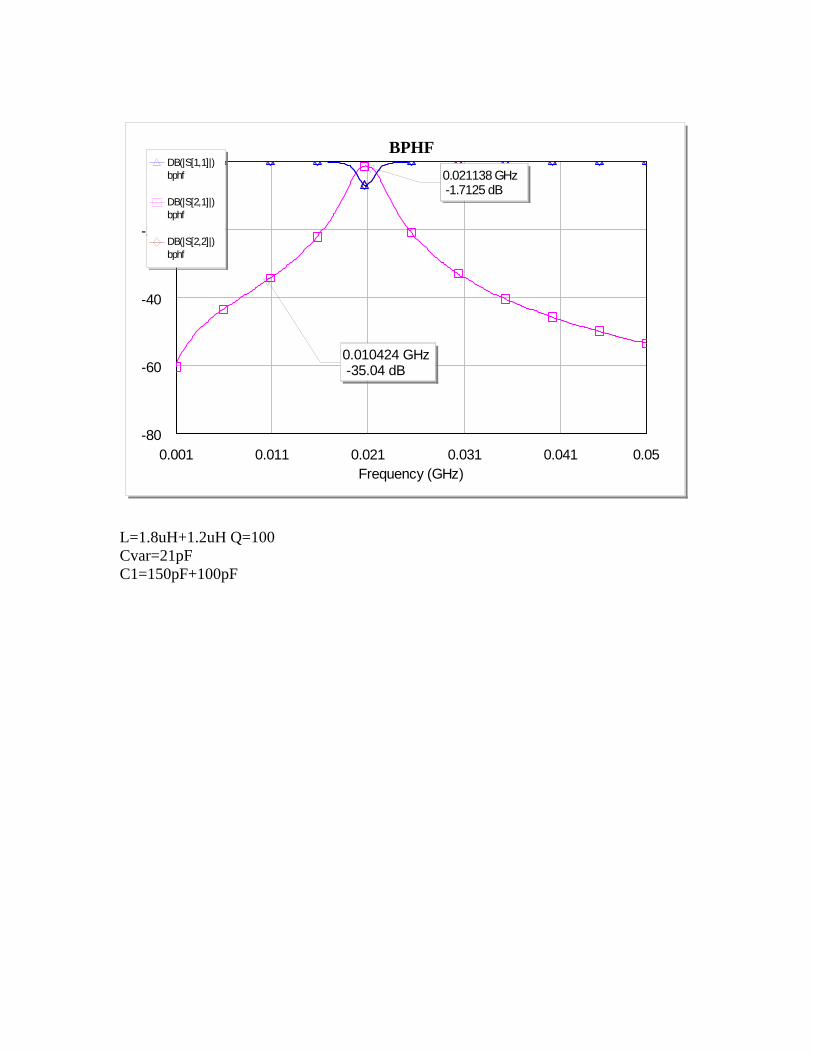
0.010424 GHz -35.04 dB
0.021138 GHz -1.7125 dB
DB(|S[1,1]|)bphf
DB(|S[2,1]|)bphf
DB(|S[2,2]|)bphf
L=1.8uH+1.2uH Q=100 Cvar=21pF C1=150pF+100pF

0.001 0.011 0.021 0.031 0.041 0.05Frequency (GHz)
BPHF
-80
-60
-40
-20
0
0.0090646 GHz -32.08 dB
0.018047 GHz -1.1095 dB
DB(|S[1,1]|)bphf
DB(|S[2,1]|)bphf
DB(|S[2,2]|)bphf
FILTER 18MHz L=1.8uH+1.2uH Q=100 Cvar=28pF C1=150pF+100pF

0.001 0.011 0.021 0.031 0.041 0.05Frequency (GHz)
BPHF
-80
-60
-40
-20
0
0.0070685 GHz -24.946 dB
0.014061 GHz -0.41101 dB
DB(|S[1,1]|)bphf
DB(|S[2,1]|)bphf
DB(|S[2,2]|)bphf
FILTER 14MHz L=1.8uH+1.2uH Q=100 Cvar=50pF C1=150pF+100pF
0.001 0.011 0.021 0.031 0.041 0.05Frequency (GHz)
BPHF
-80
-60
-40
-20
0
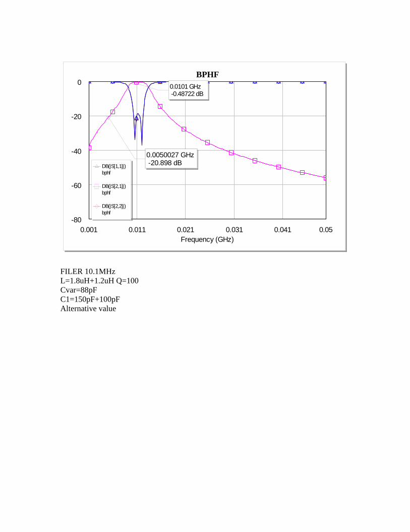
0.0050027 GHz -20.898 dB
0.0101 GHz -0.48722 dB
DB(|S[1,1]|)bphf
DB(|S[2,1]|)bphf
DB(|S[2,2]|)bphf
FILER 10.1MHz L=1.8uH+1.2uH Q=100 Cvar=88pF C1=150pF+100pF Alternative value
0.001 0.011 0.021 0.031 0.041 0.05Frequency (GHz)
BPHF
-80
-60
-40
-20
0
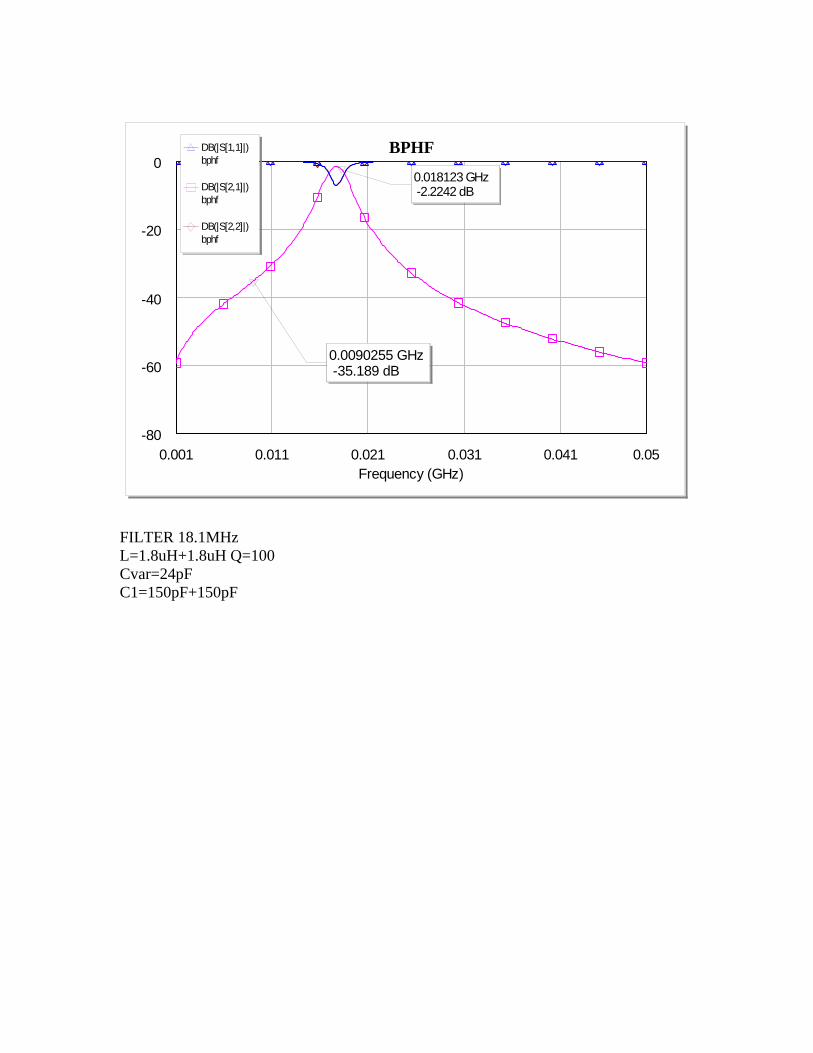
0.0090255 GHz -35.189 dB
0.018123 GHz -2.2242 dB
DB(|S[1,1]|)bphf
DB(|S[2,1]|)bphf
DB(|S[2,2]|)bphf
FILTER 18.1MHz L=1.8uH+1.8uH Q=100 Cvar=24pF C1=150pF+150pF
0.001 0.011 0.021 0.031 0.041 0.05Frequency (GHz)
BPHF
-60
-50
-40
-30
-20
-10
0
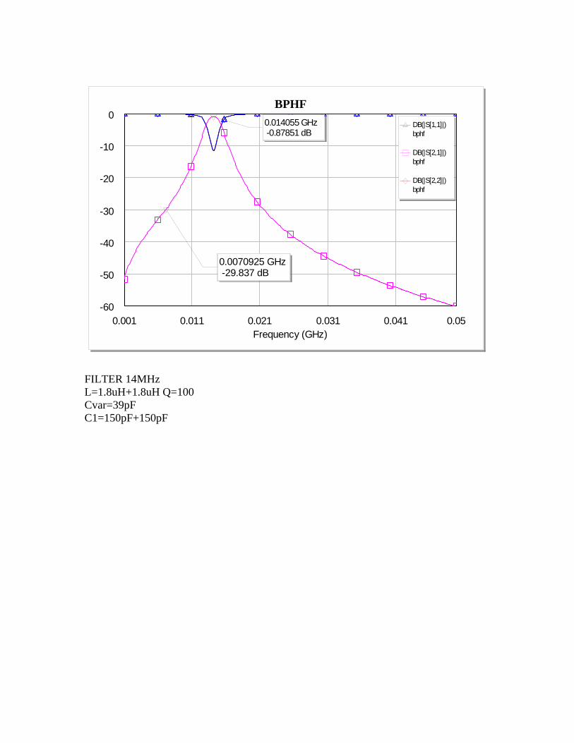
0.0070925 GHz -29.837 dB
0.014055 GHz -0.87851 dB
DB(|S[1,1]|)bphf
DB(|S[2,1]|)bphf
DB(|S[2,2]|)bphf
FILTER 14MHz L=1.8uH+1.8uH Q=100 Cvar=39pF C1=150pF+150pF
0.001 0.011 0.021 0.031 0.041 0.05Frequency (GHz)
BPHF
-80
-60
-40
-20
0
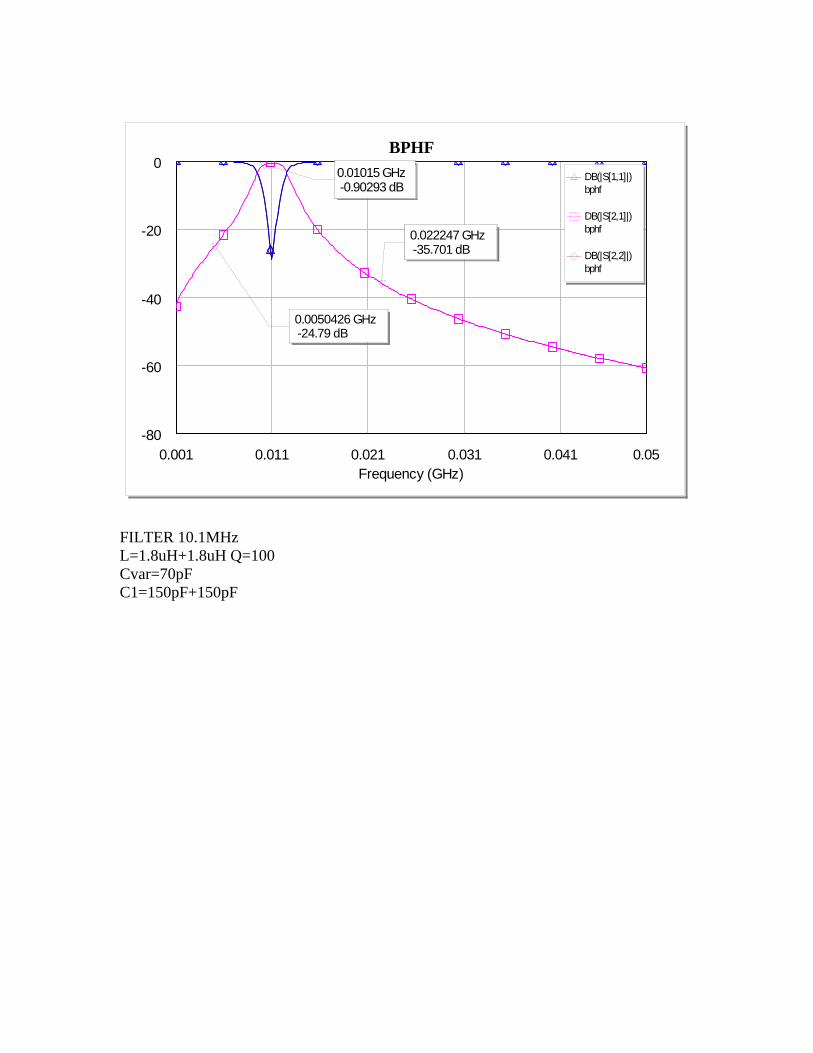
0.022247 GHz -35.701 dB
0.0050426 GHz -24.79 dB
0.01015 GHz -0.90293 dB
DB(|S[1,1]|)bphf
DB(|S[2,1]|)bphf
DB(|S[2,2]|)bphf
FILTER 10.1MHz L=1.8uH+1.8uH Q=100 Cvar=70pF C1=150pF+150pF

0.001 0.011 0.021 0.031 0.041 0.05Frequency (GHz)
BPHF
-80
-60
-40
-20
0
0.014232 GHz -21.976 dB
0.0035061 GHz -17.473 dB
0.007 GHz -0.45532 dB
DB(|S[1,1]|)bphf
DB(|S[2,1]|)bphf
DB(|S[2,2]|)bphf
FILTER 7MHz L=1.8uH+1.8uH Q=100 Cvar=155pF C1=150pF+150pF
0.0001 0.0051 0.0101 0.0151 0.02Frequency (GHz)
BPHF
-80
-60
-40
-20
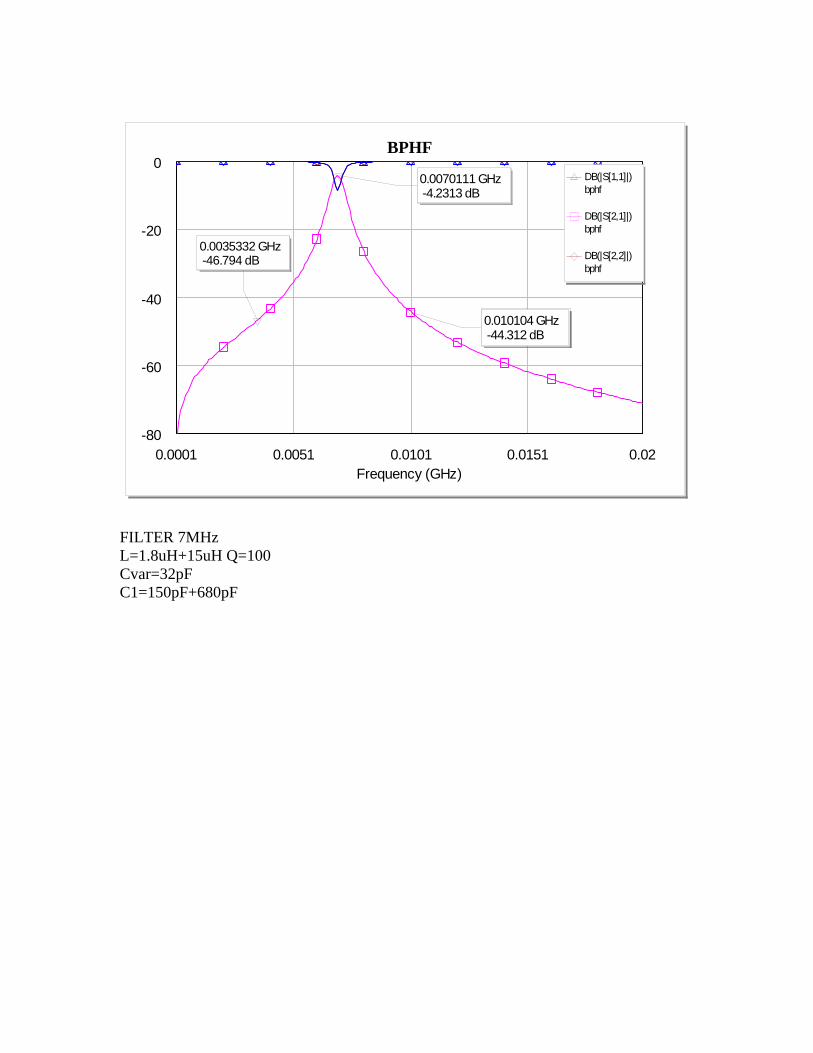
00.0070111 GHz -4.2313 dB
0.0035332 GHz -46.794 dB
0.010104 GHz -44.312 dB
DB(|S[1,1]|)bphf
DB(|S[2,1]|)bphf
DB(|S[2,2]|)bphf
FILTER 7MHz L=1.8uH+15uH Q=100 Cvar=32pF C1=150pF+680pF

0.0001 0.0051 0.0101 0.0151 0.02Frequency (GHz)
BPHF
-80
-60
-40
-20
0 0.0035647 GHz -1.8523 dB
0.0018054 GHz -30.237 dB
0.0070538 GHz -40.816 dB
DB(|S[1,1]|)bphf
DB(|S[2,1]|)bphf
DB(|S[2,2]|)bphf
FILTER 3.5MHz L=1.8uH+15uH Q=100 Cvar=130pF C1=150pF+ 680pF
0.0001 0.0051 0.0101 0.0151 0.02Frequency (GHz)
BPHF
-80
-60
-40
-20
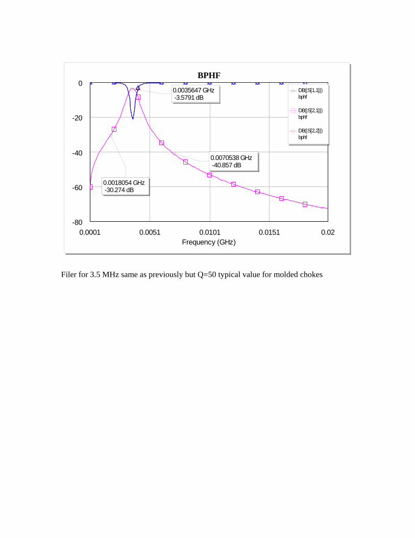
00.0035647 GHz -3.5791 dB
0.0018054 GHz -30.274 dB
0.0070538 GHz -40.857 dB
DB(|S[1,1]|)bphf
DB(|S[2,1]|)bphf
DB(|S[2,2]|)bphf
Filer for 3.5 MHz same as previously but Q=50 typical value for molded chokes

0.0001 0.0051 0.0101 0.0151 0.02Frequency (GHz)
BPHF
-80
-60
-40
-20
0
0.0035647 GHz -20.266 dB
0.0018054 GHz -1.6957 dB
0.0070538 GHz -44.471 dB
DB(|S[1,1]|)bphf
DB(|S[2,1]|)bphf
DB(|S[2,2]|)bphf
FILER 1.8MHz L=1.8uH+15uH Q=100 Cvar=500pF C1=150pF+680pF

0.0001 0.0051 0.0101 0.0151 0.02Frequency (GHz)
BPHF
-80
-60
-40
-20
0
0.0035647 GHz -22.993 dB
0.0018054 GHz -1.9647 dB
0.0070538 GHz -46.409 dB
DB(|S[1,1]|)bphf
DB(|S[2,1]|)bphf
DB(|S[2,2]|)bphf
FILTER 1.8 MHZ L=1.8uH+1.8uH+15uH Cvar=500pF C1=150pF+680pF

0.0001 0.0051 0.0101 0.0151 0.02Frequency (GHz)
BPHF
-80
-60
-40
-20
0 0.0035647 GHz -1.9616 dB
0.0018054 GHz -30.109 dB
0.0070538 GHz -43.063 dB
DB(|S[1,1]|)bphf
DB(|S[2,1]|)bphf
DB(|S[2,2]|)bphf
FILTER 3.5MHz L=1.8uH+1.8uH+15uH Q=100 Cvar=127pF C1=150pF+680pF
0.0001 0.0051 0.0101 0.0151 0.02Frequency (GHz)
BPHF
-80
-60
-40
-20
0
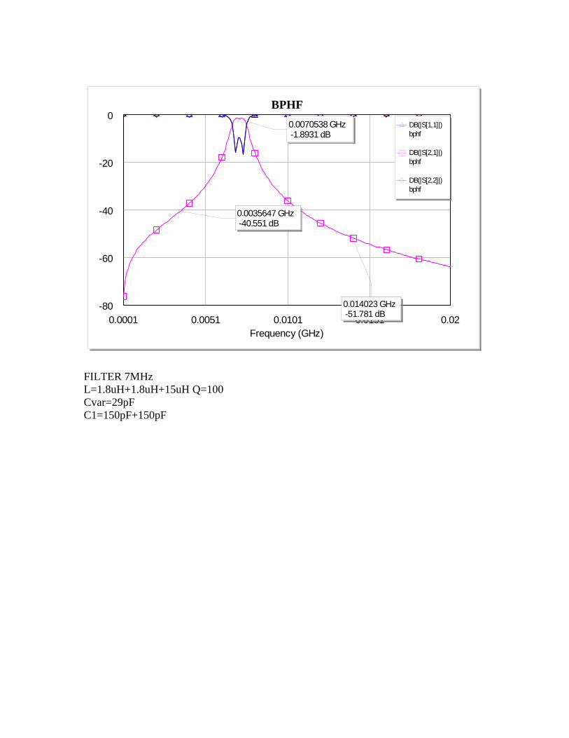
0.0035647 GHz -40.551 dB
0.014023 GHz -51.781 dB
0.0070538 GHz -1.8931 dB
DB(|S[1,1]|)bphf
DB(|S[2,1]|)bphf
DB(|S[2,2]|)bphf
FILTER 7MHz L=1.8uH+1.8uH+15uH Q=100 Cvar=29pF C1=150pF+150pF
0.0001 0.0051 0.0101 0.0151 0.02Frequency (GHz)
BPHF
-80
-60
-40
-20
0
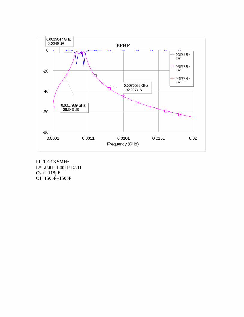
0.0035647 GHz -2.3348 dB
0.0017989 GHz -26.343 dB
0.0070538 GHz -32.297 dB
DB(|S[1,1]|)bphf
DB(|S[2,1]|)bphf
DB(|S[2,2]|)bphf
FILTER 3.5MHz L=1.8uH+1.8uH+15uH Cvar=118pF C1=150pF+150pF

0.0001 0.0051 0.0101 0.0151 0.02Frequency (GHz)
BPHF
-80
-60
-40
-20
0
0.0035647 GHz -38.926 dB
0.014115 GHz -50.222 dB
0.0070538 GHz -1.7349 dB
DB(|S[1,1]|)bphf
DB(|S[2,1]|)bphf
DB(|S[2,2]|)bphf
FILTER 7MHz L=1.8uH+15uH Cvar=32pF C1=150pF+150pF

0.0001 0.0051 0.0101 0.0151 0.02Frequency (GHz)
BPHF
-80
-60
-40
-20
0
0.0050506 GHz -39.563 dB
0.02 GHz -53.847 dB
0.010107 GHz -1.6923 dB
DB(|S[1,1]|)bphf
DB(|S[2,1]|)bphf
DB(|S[2,2]|)bphf
FILTER 10.1MHz L=1.8uH+15uH Q=100 Cvar=18pF (some variable capacitor can reach this value) C1=150pF